EP0631437A2 - System for recording teletext data - Google Patents
System for recording teletext data Download PDFInfo
- Publication number
- EP0631437A2 EP0631437A2 EP94110004A EP94110004A EP0631437A2 EP 0631437 A2 EP0631437 A2 EP 0631437A2 EP 94110004 A EP94110004 A EP 94110004A EP 94110004 A EP94110004 A EP 94110004A EP 0631437 A2 EP0631437 A2 EP 0631437A2
- Authority
- EP
- European Patent Office
- Prior art keywords
- teletext data
- data
- teletext
- signal
- recording
- Prior art date
- Legal status (The legal status is an assumption and is not a legal conclusion. Google has not performed a legal analysis and makes no representation as to the accuracy of the status listed.)
- Granted
Links
Images


Classifications
-
- H—ELECTRICITY
- H04—ELECTRIC COMMUNICATION TECHNIQUE
- H04N—PICTORIAL COMMUNICATION, e.g. TELEVISION
- H04N5/00—Details of television systems
- H04N5/76—Television signal recording
- H04N5/91—Television signal processing therefor
- H04N5/92—Transformation of the television signal for recording, e.g. modulation, frequency changing; Inverse transformation for playback
- H04N5/9201—Transformation of the television signal for recording, e.g. modulation, frequency changing; Inverse transformation for playback involving the multiplexing of an additional signal and the video signal
- H04N5/9206—Transformation of the television signal for recording, e.g. modulation, frequency changing; Inverse transformation for playback involving the multiplexing of an additional signal and the video signal the additional signal being a character code signal
- H04N5/9207—Transformation of the television signal for recording, e.g. modulation, frequency changing; Inverse transformation for playback involving the multiplexing of an additional signal and the video signal the additional signal being a character code signal for teletext
Definitions
- the present invention relates to a system for recording data of a teletext broadcast, and more particularly to a system for simultaneously recording the teletext data and video data of a television signal or the same recording medium.
- the teletext is a new type of multiplex broadcasting system where information other than regular television programs in the form of characters, simple graphics and additional sounds is transmitted. The information is repeatedly transmitted so that a user may receive the information he chooses at any chosen time.
- the teletext data in the form of digital signal are carried during the vertical retrace line interval which is an empty time space in the television signal.
- the user may watch any teletext program of his choice on a television receiver having a built-in decoder, or an ordinary television receiver having a teletext adapter connected thereto.
- the data are decoded and converted into a television signal, which is recorded by a VCR.
- the teletext data is applied to a personal computer, which is operated by an exclusive keyboard and stored on a hard disc.
- a television receiver receives broadcast waves through an antenna.
- the wave of a particular channel which is selected by a television tuner 1 is converted into a television signal.
- Teletext data included in the television signal is derived at a teletext decoder 2 and recorded at a VCR 3 on a recording tape in a video cassette.
- the data is also fed to a television monitor 4 on which the data is shown.
- Fig. 4 shows the second recording system where the broadcast wave converted into the television signal at the television tuner 1 is fed to a personal computer 5.
- the user operates an operation keyboard 6 connected to the computer 5 to extract the teletext data from the television signal and to correct errors included therein.
- the teletext data is then recorded on a hard disc 8.
- the personal computer 5 processes the data on the hard disc 8 and shows it on a screen of a CRT display 7.
- the VCR has a pair of heads provided on opposite sides of a rotating drum with which a tape is contacted.
- One of the heads scans odd fields, and the other head scans even fields.
- the heads are switched in the vertical retrace line interval for completing one whole picture frame.
- the teletext data are transmitted during lines 13H, 15H, 16H and 21H in the vertical retrace line interval. Therefore, the transmission period may overlap with the switching time of the heads, which causes it likely to skip the teletext data at recording. Hence in the conventional systems, the teletext data and the video data can not be recorded on the same medium at the same time.
- An object of the present invention is to provide a system for simultaneously recording the teletext data and video data on the same medium.
- a system for recording teletext data included in a video signal on a tape by a recording device having a pair of heads which are switched at every field wherein the system comprises detector means for detecting teletext data, shifting means for shifting detected teletext data to a position in the video signal where the detected teletext data do not overlap with the switching time of the heads, and output means for outputting the video signal including the shifted teletext data to the recording device.
- Fig. 1 shows an example of a teletext recording system according to an embodiment of the present invention wherein the teletext data and television data are recorded on a video tape.
- the same numerals in Fig. 1 as in Fig. 3 indicate the same parts in Fig. 1.
- the broadcast wave is tuned in by operating the tuner 1 and applied thereto through the antenna where the broadcast wave is converted into a television signal.
- the television signal is fed to an A/D converter 18 through a switch SW1 and a buffer 9 so as to be converted into a digital signal.
- the switch SW1 is also connected to a VCR so as to selectively connect the buffer 9 with the VCR when reproducing recorded data.
- the digital television signal including the teletext data transmitted during lines 14H, 15H, 16H and 21H of the vertical retrace interval is fed to a field memory 15 wherein the teletext data are stored.
- the field memory 15 is connected to a D/A converter 19 through an information adding circuit 17 and converted into an analog teletext signal.
- the analog teletext signal is fed to a waveform shaping circuit 22, thereby restraining the influence of the carrier waves and a filter of the VCR. Only the teletext signal may be shaped at the shaping circuit 22 so that an optimum waveform is obtained without affecting the picture image created by the television signal.
- the waveform shaping circuit 22 is selectively connected to a VCR and a television monitor through a switch SW2.
- the television signal is further fed from the tuner 1 to a color burst signal extracting circuit 10 where a color burst signal is extracted from the television signal.
- the color burst signal is applied to a PLL 11 to generate clock pulses based thereon. Namely, the color burst signal is phase-locked and converted into a clock signal having a frequency which is four times as high as the original subcarrier (burst) signal.
- the clock pulses are fed from the PLL 11 to the A/D converter 18, field memory 15, information adding circuit 17, D/A converter 19, a sync separator 12, reset pulse generator 13, address controller 14, system controller 16, and an additional information determining circuit 20, respectively, thereby controlling the operational timing of the entire system.
- the digital television signal from the A/D converter 18 is further fed to the additional information deciding circuit 20 and the sync separator 12.
- a horizontal sync signal H and a vertical sync signal V are extracted from the television signal.
- Horizontal driving pulses HD and vertical driving pulses VD are produced from the horizontal and vertical sync signals H and V, respectively.
- the pulses are fed to a reset pulse generator 13 which accordingly generates reference control signals in the form of horizontal reset pulses HRP and vertical reset pulses VRP so as to control the addresses of the field memory 15.
- the vertical reset pulse VRP resets both the addresses of the rows and column of the field memory 15 to zero, while the horizontal reset pulse HRP resets the column address and increases the row addresses one by one.
- the column address is increased with every clock pulse fed from the PLL 11 one by one.
- the address controller 14, in response to the reset pulses HRP and VRP, applies a signal to the field memory 15. Namely, when the row address of the field memory 15 reaches those corresponding to the lines 14H, 15H, 16H and 21H, data in the period are stored at the addresses corresponding to the lines 21H, 22H, 23H and 24H, respectively. When the row address reaches those of the lines 22H, 23H and 24H, data in the period are stored at the addresses corresponding to the lines 14H, 15H and 16H, respectively. Namely, teletext data are stored at the row addresses corresponding to 21H, 22H, 23H and 24H lines.
- the address controller 14 is fed with standard signals such as read horizontal reset pulse and read vertical reset pulse from a signal generator 21 for reading out data from the field memory 15.
- standard signals such as read horizontal reset pulse and read vertical reset pulse from a signal generator 21 for reading out data from the field memory 15.
- the address of the read out data is reset, thereby controlling the reading of the field memory.
- the address controller 14 further feeds a control signal to the system controller 16 which in response applies a signal to the information adding circuit 17.
- the line information on 14H, 15H, 16H and 21H, that is, data on the original addresses of the teletext data are added to the data read out from the field memory 15.
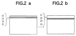
- the derived teletext data is converted into an analog signal at a D/A converter 19 and shaped at a waveform shaping circuit 22, and fed to the VCR to be recorded. Since, the teletext data is moved from the lines 14H, 15H, 16H and 21H shown in Fig. 2a to the lines 21H, 22H, 23H and 24H shown in Fig. 2b, the period of which does not overlap with the switching time of the heads, the data are not erased.
- the connections of the switches SW1 and SW2 are changed to connect the input to the VCR and the output to the television monitor.
- the television signal carrying the teletext data on the lines 21H, 22H, 23H and 24H is fed to the field monitor 15.
- the addresses of the data are converted to the addresses of 14H, 15H, 16H and 21H at the field memory based on the data added at the information adding circuit 17. Therefore, the original signal which can be applied to the conventional decoder 2 shown in Fig. 3 is restored.
- the teletext data is displayed on the television monitor.
- the teletext data may be moved to other lines besides 21H, 22H, 23H and 24H.
- the position in the television signal in the television signal is moved from an area at which the video heads are switched.
- the teletext data are accurately recorded and reproduced together with the video signal.
- the lines on which the teletext data are provided become closer to the effective area of picture, by decreasing the level of the teletext data, the effect on the picture is restrained.
- the data on the original line positions of the teletext data are added at the information adding circuit 17, the lines may be freely moved to various positions without considering the model of the VCR equipment to be used.
Abstract
Description
- The present invention relates to a system for recording data of a teletext broadcast, and more particularly to a system for simultaneously recording the teletext data and video data of a television signal or the same recording medium.
- The teletext is a new type of multiplex broadcasting system where information other than regular television programs in the form of characters, simple graphics and additional sounds is transmitted. The information is repeatedly transmitted so that a user may receive the information he chooses at any chosen time.
- The teletext data in the form of digital signal are carried during the vertical retrace line interval which is an empty time space in the television signal. The user may watch any teletext program of his choice on a television receiver having a built-in decoder, or an ordinary television receiver having a teletext adapter connected thereto.
- In one of the systems for recording the teletext data, the data are decoded and converted into a television signal, which is recorded by a VCR.
- In another system, the teletext data is applied to a personal computer, which is operated by an exclusive keyboard and stored on a hard disc.
- Referring to Fig. 3 showing the first system, a television receiver receives broadcast waves through an antenna. The wave of a particular channel which is selected by a
television tuner 1 is converted into a television signal. Teletext data included in the television signal is derived at ateletext decoder 2 and recorded at aVCR 3 on a recording tape in a video cassette. The data is also fed to atelevision monitor 4 on which the data is shown. - Fig. 4 shows the second recording system where the broadcast wave converted into the television signal at the
television tuner 1 is fed to apersonal computer 5. The user operates anoperation keyboard 6 connected to thecomputer 5 to extract the teletext data from the television signal and to correct errors included therein. The teletext data is then recorded on ahard disc 8. When reproducing the data, thepersonal computer 5 processes the data on thehard disc 8 and shows it on a screen of aCRT display 7. - The VCR has a pair of heads provided on opposite sides of a rotating drum with which a tape is contacted. One of the heads scans odd fields, and the other head scans even fields. Hence, the heads are switched in the vertical retrace line interval for completing one whole picture frame.
- On the other hand, the teletext data are transmitted during lines 13H, 15H, 16H and 21H in the vertical retrace line interval. Therefore, the transmission period may overlap with the switching time of the heads, which causes it likely to skip the teletext data at recording. Hence in the conventional systems, the teletext data and the video data can not be recorded on the same medium at the same time.
- An object of the present invention is to provide a system for simultaneously recording the teletext data and video data on the same medium.
- According to the present invention, there is provided a system for recording teletext data included in a video signal on a tape by a recording device having a pair of heads which are switched at every field, wherein the system comprises detector means for detecting teletext data, shifting means for shifting detected teletext data to a position in the video signal where the detected teletext data do not overlap with the switching time of the heads, and output means for outputting the video signal including the shifted teletext data to the recording device.
- The other objects and advantages of this invention will become understood from the following description of embodiments with reference to the accompanying drawings.
- Fig. 1 is a block diagram showing a system for recording teletext data according to an embodiment of the present invention;
- Figs. 2a and 2b show lines in vertical retrace interval of a video signal over which text data are transmitted;
- Fig. 3 is a block diagram showing the conventional system for receiving and recording teletext data on a VCR; and
- Fig. 4 is a block diagram showing a conventional system for recording the teletext data on a hard disc.
- Fig. 1 shows an example of a teletext recording system according to an embodiment of the present invention wherein the teletext data and television data are recorded on a video tape. The same numerals in Fig. 1 as in Fig. 3 indicate the same parts in Fig. 1. The broadcast wave is tuned in by operating the
tuner 1 and applied thereto through the antenna where the broadcast wave is converted into a television signal. The television signal is fed to an A/D converter 18 through a switch SW₁ and abuffer 9 so as to be converted into a digital signal. The switch SW₁ is also connected to a VCR so as to selectively connect thebuffer 9 with the VCR when reproducing recorded data. The digital television signal including the teletext data transmitted during lines 14H, 15H, 16H and 21H of the vertical retrace interval is fed to afield memory 15 wherein the teletext data are stored. - The
field memory 15 is connected to a D/A converter 19 through aninformation adding circuit 17 and converted into an analog teletext signal. The analog teletext signal is fed to awaveform shaping circuit 22, thereby restraining the influence of the carrier waves and a filter of the VCR. Only the teletext signal may be shaped at theshaping circuit 22 so that an optimum waveform is obtained without affecting the picture image created by the television signal. Thewaveform shaping circuit 22 is selectively connected to a VCR and a television monitor through a switch SW₂. - The television signal is further fed from the
tuner 1 to a color burstsignal extracting circuit 10 where a color burst signal is extracted from the television signal. The color burst signal is applied to aPLL 11 to generate clock pulses based thereon. Namely, the color burst signal is phase-locked and converted into a clock signal having a frequency which is four times as high as the original subcarrier (burst) signal. - The clock pulses are fed from the
PLL 11 to the A/D converter 18,field memory 15,information adding circuit 17, D/A converter 19, async separator 12,reset pulse generator 13,address controller 14,system controller 16, and an additionalinformation determining circuit 20, respectively, thereby controlling the operational timing of the entire system. - The digital television signal from the A/
D converter 18 is further fed to the additionalinformation deciding circuit 20 and thesync separator 12. At thesync separator 12, a horizontal sync signal H and a vertical sync signal V are extracted from the television signal. Horizontal driving pulses HD and vertical driving pulses VD are produced from the horizontal and vertical sync signals H and V, respectively. The pulses are fed to areset pulse generator 13 which accordingly generates reference control signals in the form of horizontal reset pulses HRP and vertical reset pulses VRP so as to control the addresses of thefield memory 15. - The vertical reset pulse VRP resets both the addresses of the rows and column of the
field memory 15 to zero, while the horizontal reset pulse HRP resets the column address and increases the row addresses one by one. The column address is increased with every clock pulse fed from the PLL 11 one by one. - The
address controller 14, in response to the reset pulses HRP and VRP, applies a signal to thefield memory 15. Namely, when the row address of thefield memory 15 reaches those corresponding to the lines 14H, 15H, 16H and 21H, data in the period are stored at the addresses corresponding to the lines 21H, 22H, 23H and 24H, respectively. When the row address reaches those of the lines 22H, 23H and 24H, data in the period are stored at the addresses corresponding to the lines 14H, 15H and 16H, respectively. Namely, teletext data are stored at the row addresses corresponding to 21H, 22H, 23H and 24H lines. - The
address controller 14 is fed with standard signals such as read horizontal reset pulse and read vertical reset pulse from asignal generator 21 for reading out data from thefield memory 15. When the standard signal is applied, the address of the read out data is reset, thereby controlling the reading of the field memory. Thus, data stored at the addresses corresponding to the 21H, 22H, 23H and 24H lines are read out. - The address controller 14 further feeds a control signal to the
system controller 16 which in response applies a signal to theinformation adding circuit 17. The line information on 14H, 15H, 16H and 21H, that is, data on the original addresses of the teletext data are added to the data read out from thefield memory 15. - The derived teletext data is converted into an analog signal at a D/
A converter 19 and shaped at awaveform shaping circuit 22, and fed to the VCR to be recorded. Since, the teletext data is moved from the lines 14H, 15H, 16H and 21H shown in Fig. 2a to the lines 21H, 22H, 23H and 24H shown in Fig. 2b, the period of which does not overlap with the switching time of the heads, the data are not erased. - In order to reproduce the recorded teletext data, the connections of the switches SW₁ and SW₂ are changed to connect the input to the VCR and the output to the television monitor. The television signal carrying the teletext data on the lines 21H, 22H, 23H and 24H is fed to the
field monitor 15. The addresses of the data are converted to the addresses of 14H, 15H, 16H and 21H at the field memory based on the data added at theinformation adding circuit 17. Therefore, the original signal which can be applied to theconventional decoder 2 shown in Fig. 3 is restored. - Hence the teletext data is displayed on the television monitor.
- The teletext data may be moved to other lines besides 21H, 22H, 23H and 24H.
- According to the present invention, the position in the television signal in the television signal is moved from an area at which the video heads are switched. Thus the teletext data are accurately recorded and reproduced together with the video signal. Although the lines on which the teletext data are provided become closer to the effective area of picture, by decreasing the level of the teletext data, the effect on the picture is restrained.
- The data on the original line positions of the teletext data are added at the
information adding circuit 17, the lines may be freely moved to various positions without considering the model of the VCR equipment to be used. - While the presently preferred embodiments of the present invention have been shown and described, it is to be understood that these disclosures are for the purpose of illustration and that various changes and modifications may be made without departing from the scope of the invention as set forth in the appended claims.
Claims (3)
- A system for recording teletext data contained in a video signal on a tape by a recording device (VCR) having a pair of heads which are switched at every field, the system comprising:
detector means (10 - 14) for detecting teletext data;
shifting means (16) for shifting detected teletext data to a position in the video signal where the detected teletext data do not overlap with a switching time of the heads; and
output means (19, 22) for outputting the video signal including the shifted teletext data to the recording device (VCR). - The system according to claim 1, wherein the detected teletext data are stored in a memory (15) at addresses which are shifted to addresses where the teletext data do not overlap with the switching timing.
- The system according to claim 2, further comprising information adding means (17) for adding information on an original address of the teletext data to teletext data derived from the memory (15).
Applications Claiming Priority (2)
| Application Number | Priority Date | Filing Date | Title |
|---|---|---|---|
| JP5157466A JPH0738841A (en) | 1993-06-28 | 1993-06-28 | Auxiliary device for teletext recording |
| JP157466/93 | 1993-06-28 |
Publications (3)
| Publication Number | Publication Date |
|---|---|
| EP0631437A2 true EP0631437A2 (en) | 1994-12-28 |
| EP0631437A3 EP0631437A3 (en) | 1995-08-02 |
| EP0631437B1 EP0631437B1 (en) | 1998-09-02 |
Family
ID=15650291
Family Applications (1)
| Application Number | Title | Priority Date | Filing Date |
|---|---|---|---|
| EP19940110004 Expired - Lifetime EP0631437B1 (en) | 1993-06-28 | 1994-06-28 | System for recording teletext data |
Country Status (3)
| Country | Link |
|---|---|
| EP (1) | EP0631437B1 (en) |
| JP (1) | JPH0738841A (en) |
| DE (1) | DE69412928T2 (en) |
Cited By (5)
| Publication number | Priority date | Publication date | Assignee | Title |
|---|---|---|---|---|
| US9071872B2 (en) | 2003-01-30 | 2015-06-30 | Rovi Guides, Inc. | Interactive television systems with digital video recording and adjustable reminders |
| US9100686B2 (en) | 1998-09-17 | 2015-08-04 | Rovi Guides, Inc. | Electronic program guide with digital storage |
| US9294799B2 (en) | 2000-10-11 | 2016-03-22 | Rovi Guides, Inc. | Systems and methods for providing storage of data on servers in an on-demand media delivery system |
| US10063934B2 (en) | 2008-11-25 | 2018-08-28 | Rovi Technologies Corporation | Reducing unicast session duration with restart TV |
| US10075746B2 (en) | 1998-07-14 | 2018-09-11 | Rovi Guides, Inc. | Client-server based interactive television guide with server recording |
Families Citing this family (2)
| Publication number | Priority date | Publication date | Assignee | Title |
|---|---|---|---|---|
| JPH11134345A (en) * | 1997-10-27 | 1999-05-21 | Fuji Xerox Co Ltd | Favorite information selecting device |
| US8805418B2 (en) | 2011-12-23 | 2014-08-12 | United Video Properties, Inc. | Methods and systems for performing actions based on location-based rules |
Citations (2)
| Publication number | Priority date | Publication date | Assignee | Title |
|---|---|---|---|---|
| EP0065378A2 (en) * | 1981-05-07 | 1982-11-24 | THORN EMI Ferguson Limited | Video recording equipment |
| US5181113A (en) * | 1990-05-10 | 1993-01-19 | Goldstar Co., Ltd. | Method of storing and editing data in a television system and apparatus therefor |
-
1993
- 1993-06-28 JP JP5157466A patent/JPH0738841A/en active Pending
-
1994
- 1994-06-28 DE DE1994612928 patent/DE69412928T2/en not_active Expired - Fee Related
- 1994-06-28 EP EP19940110004 patent/EP0631437B1/en not_active Expired - Lifetime
Patent Citations (2)
| Publication number | Priority date | Publication date | Assignee | Title |
|---|---|---|---|---|
| EP0065378A2 (en) * | 1981-05-07 | 1982-11-24 | THORN EMI Ferguson Limited | Video recording equipment |
| US5181113A (en) * | 1990-05-10 | 1993-01-19 | Goldstar Co., Ltd. | Method of storing and editing data in a television system and apparatus therefor |
Non-Patent Citations (1)
| Title |
|---|
| IEEE TRANSACTIONS ON CONSUMER ELECTRONICS, vol. 35, no. 4, November 1989 NEW YORK US, pages 797-802, ICHINOI ET AL 'recording and decoding of teletext signal with s-vhs vcr' * |
Cited By (9)
| Publication number | Priority date | Publication date | Assignee | Title |
|---|---|---|---|---|
| US10075746B2 (en) | 1998-07-14 | 2018-09-11 | Rovi Guides, Inc. | Client-server based interactive television guide with server recording |
| US9100686B2 (en) | 1998-09-17 | 2015-08-04 | Rovi Guides, Inc. | Electronic program guide with digital storage |
| US9106947B2 (en) | 1998-09-17 | 2015-08-11 | Rovi Guides, Inc. | Electronic program guide with digital storage |
| US9237371B2 (en) | 1998-09-17 | 2016-01-12 | Rovi Guides, Inc. | Electronic program guide with digital storage |
| US9363553B2 (en) | 1998-09-17 | 2016-06-07 | Rovi Guides, Inc. | Electronic program guide with digital storage |
| US9294799B2 (en) | 2000-10-11 | 2016-03-22 | Rovi Guides, Inc. | Systems and methods for providing storage of data on servers in an on-demand media delivery system |
| US9071872B2 (en) | 2003-01-30 | 2015-06-30 | Rovi Guides, Inc. | Interactive television systems with digital video recording and adjustable reminders |
| US9369741B2 (en) | 2003-01-30 | 2016-06-14 | Rovi Guides, Inc. | Interactive television systems with digital video recording and adjustable reminders |
| US10063934B2 (en) | 2008-11-25 | 2018-08-28 | Rovi Technologies Corporation | Reducing unicast session duration with restart TV |
Also Published As
| Publication number | Publication date |
|---|---|
| DE69412928D1 (en) | 1998-10-08 |
| JPH0738841A (en) | 1995-02-07 |
| DE69412928T2 (en) | 1999-04-15 |
| EP0631437B1 (en) | 1998-09-02 |
| EP0631437A3 (en) | 1995-08-02 |
Similar Documents
| Publication | Publication Date | Title |
|---|---|---|
| US4635132A (en) | Printer used for a television receiver | |
| JP2972069B2 (en) | Broadcast system display | |
| US4768095A (en) | Apparatus for processing image | |
| EP0631437B1 (en) | System for recording teletext data | |
| JP3336843B2 (en) | Video equipment | |
| KR19980034812A (en) | Video Television (TVCR) system and method for controlling playback operation according to PIP function setting | |
| JPS62181A (en) | Video processing device | |
| EP0172572B1 (en) | Televison sync signal processing circuit | |
| US6289168B2 (en) | Video tape recorder with a function of controlling a character display | |
| KR100231646B1 (en) | Method for repeatedly controlling reading of caption data in vcr | |
| KR930009177B1 (en) | Picture image playback apparatus and method | |
| KR970009458B1 (en) | Method and apparatus of pip display system using one tuner | |
| JP3464229B2 (en) | Method and apparatus for synchronizing control function to video signal in television receiver | |
| JPH09200684A (en) | Video/audio signal recording device | |
| JPS612478A (en) | Multi-screen display television receiver | |
| KR0131980B1 (en) | Method and apparatus for displaying double pip | |
| JP2538402B2 (en) | Video tape recorder | |
| JP2773879B2 (en) | On-screen display device | |
| KR910002606B1 (en) | Teletext receiver circuit | |
| JPS6349235B2 (en) | ||
| KR100193090B1 (en) | Digital image retrieval device and its method when watching TVCR | |
| KR20000033416A (en) | Vcr system with caption function | |
| JPH06178318A (en) | Text multiplexed broadcasting playback system of video recording and playback apparatus | |
| JPH0247981A (en) | High definition television signal digital recording and reproducing device | |
| JPS62182A (en) | Video processing device |
Legal Events
| Date | Code | Title | Description |
|---|---|---|---|
| PUAI | Public reference made under article 153(3) epc to a published international application that has entered the european phase |
Free format text: ORIGINAL CODE: 0009012 |
|
| AK | Designated contracting states |
Kind code of ref document: A2 Designated state(s): DE FR GB |
|
| PUAL | Search report despatched |
Free format text: ORIGINAL CODE: 0009013 |
|
| AK | Designated contracting states |
Kind code of ref document: A3 Designated state(s): DE FR GB |
|
| 17P | Request for examination filed |
Effective date: 19950912 |
|
| GRAG | Despatch of communication of intention to grant |
Free format text: ORIGINAL CODE: EPIDOS AGRA |
|
| 17Q | First examination report despatched |
Effective date: 19971111 |
|
| GRAG | Despatch of communication of intention to grant |
Free format text: ORIGINAL CODE: EPIDOS AGRA |
|
| GRAH | Despatch of communication of intention to grant a patent |
Free format text: ORIGINAL CODE: EPIDOS IGRA |
|
| GRAH | Despatch of communication of intention to grant a patent |
Free format text: ORIGINAL CODE: EPIDOS IGRA |
|
| GRAA | (expected) grant |
Free format text: ORIGINAL CODE: 0009210 |
|
| AK | Designated contracting states |
Kind code of ref document: B1 Designated state(s): DE FR GB |
|
| REF | Corresponds to: |
Ref document number: 69412928 Country of ref document: DE Date of ref document: 19981008 |
|
| ET | Fr: translation filed | ||
| REG | Reference to a national code |
Ref country code: GB Ref legal event code: 746 Effective date: 19990525 |
|
| PLBE | No opposition filed within time limit |
Free format text: ORIGINAL CODE: 0009261 |
|
| STAA | Information on the status of an ep patent application or granted ep patent |
Free format text: STATUS: NO OPPOSITION FILED WITHIN TIME LIMIT |
|
| REG | Reference to a national code |
Ref country code: FR Ref legal event code: D6 |
|
| 26N | No opposition filed | ||
| REG | Reference to a national code |
Ref country code: GB Ref legal event code: IF02 |
|
| PGFP | Annual fee paid to national office [announced via postgrant information from national office to epo] |
Ref country code: GB Payment date: 20020605 Year of fee payment: 9 |
|
| PGFP | Annual fee paid to national office [announced via postgrant information from national office to epo] |
Ref country code: FR Payment date: 20020617 Year of fee payment: 9 |
|
| PGFP | Annual fee paid to national office [announced via postgrant information from national office to epo] |
Ref country code: DE Payment date: 20020827 Year of fee payment: 9 |
|
| PG25 | Lapsed in a contracting state [announced via postgrant information from national office to epo] |
Ref country code: GB Free format text: LAPSE BECAUSE OF NON-PAYMENT OF DUE FEES Effective date: 20030628 |
|
| PG25 | Lapsed in a contracting state [announced via postgrant information from national office to epo] |
Ref country code: DE Free format text: LAPSE BECAUSE OF NON-PAYMENT OF DUE FEES Effective date: 20040101 |
|
| GBPC | Gb: european patent ceased through non-payment of renewal fee |
Effective date: 20030628 |
|
| PG25 | Lapsed in a contracting state [announced via postgrant information from national office to epo] |
Ref country code: FR Free format text: LAPSE BECAUSE OF NON-PAYMENT OF DUE FEES Effective date: 20040227 |
|
| REG | Reference to a national code |
Ref country code: FR Ref legal event code: ST |