EP0631202A2 - Customer schedulable machine quality adjust - Google Patents
Customer schedulable machine quality adjust Download PDFInfo
- Publication number
- EP0631202A2 EP0631202A2 EP94303624A EP94303624A EP0631202A2 EP 0631202 A2 EP0631202 A2 EP 0631202A2 EP 94303624 A EP94303624 A EP 94303624A EP 94303624 A EP94303624 A EP 94303624A EP 0631202 A2 EP0631202 A2 EP 0631202A2
- Authority
- EP
- European Patent Office
- Prior art keywords
- checking
- image quality
- image processing
- machine
- monitoring element
- Prior art date
- Legal status (The legal status is an assumption and is not a legal conclusion. Google has not performed a legal analysis and makes no representation as to the accuracy of the status listed.)
- Granted
Links
Images


Classifications
-
- G—PHYSICS
- G03—PHOTOGRAPHY; CINEMATOGRAPHY; ANALOGOUS TECHNIQUES USING WAVES OTHER THAN OPTICAL WAVES; ELECTROGRAPHY; HOLOGRAPHY
- G03G—ELECTROGRAPHY; ELECTROPHOTOGRAPHY; MAGNETOGRAPHY
- G03G15/00—Apparatus for electrographic processes using a charge pattern
- G03G15/55—Self-diagnostics; Malfunction or lifetime display
-
- H—ELECTRICITY
- H04—ELECTRIC COMMUNICATION TECHNIQUE
- H04N—PICTORIAL COMMUNICATION, e.g. TELEVISION
- H04N1/00—Scanning, transmission or reproduction of documents or the like, e.g. facsimile transmission; Details thereof
- H04N1/00002—Diagnosis, testing or measuring; Detecting, analysing or monitoring not otherwise provided for
- H04N1/00026—Methods therefor
- H04N1/00029—Diagnosis, i.e. identifying a problem by comparison with a normal state
-
- H—ELECTRICITY
- H04—ELECTRIC COMMUNICATION TECHNIQUE
- H04N—PICTORIAL COMMUNICATION, e.g. TELEVISION
- H04N1/00—Scanning, transmission or reproduction of documents or the like, e.g. facsimile transmission; Details thereof
- H04N1/00002—Diagnosis, testing or measuring; Detecting, analysing or monitoring not otherwise provided for
- H04N1/00026—Methods therefor
- H04N1/00055—Methods therefor automatically on a periodic basis
-
- H—ELECTRICITY
- H04—ELECTRIC COMMUNICATION TECHNIQUE
- H04N—PICTORIAL COMMUNICATION, e.g. TELEVISION
- H04N1/00—Scanning, transmission or reproduction of documents or the like, e.g. facsimile transmission; Details thereof
- H04N1/00002—Diagnosis, testing or measuring; Detecting, analysing or monitoring not otherwise provided for
- H04N1/00071—Diagnosis, testing or measuring; Detecting, analysing or monitoring not otherwise provided for characterised by the action taken
- H04N1/00082—Adjusting or controlling
-
- H—ELECTRICITY
- H04—ELECTRIC COMMUNICATION TECHNIQUE
- H04N—PICTORIAL COMMUNICATION, e.g. TELEVISION
- H04N1/00—Scanning, transmission or reproduction of documents or the like, e.g. facsimile transmission; Details thereof
- H04N1/32—Circuits or arrangements for control or supervision between transmitter and receiver or between image input and image output device, e.g. between a still-image camera and its memory or between a still-image camera and a printer device
- H04N1/32561—Circuits or arrangements for control or supervision between transmitter and receiver or between image input and image output device, e.g. between a still-image camera and its memory or between a still-image camera and a printer device using a programmed control device, e.g. a microprocessor
Definitions
- the invention relates to image quality adjustments and more particularly, to customer schedulable machine quality adjustment in an image reproduction machine.
- a method of presetting events for checking in an image processing apparatus having image processing components for forming images on a medium, and a controller for directing the operation of the image processing components including a user interface and a monitoring element for checking the operation of the apparatus in one or more modes, the method comprising: providing a plurality of presetting events options, selecting one or more presetting event options to set one or more options for checking the apparatus by the monitoring element, storing the selected event options for checking of the apparatus in the controller, and responding to said selected event option or options to activate the monitoring element for checking the apparatus.
- the present invention is concerned with a method of presetting the time for automatically checking a machine and making quality adjustments in the machine by an image quality monitoring element by providing a plurality of presetting time options on a screen display of a user interface, selecting a set of preset times to initiate checking the machine by the image quality monitoring element, storing in the controller the set of preset times to initiate checking the machine by the image quality monitoring element , and responding to the set of preset times to activate the image quality monitoring element.
- a controller for directing the operation of the image processing components including a user interface and an image quality monitoring element for checking the operation of the machine in relation to image quality standards there is provided a method of presetting the time for checking of the machine in relation to image quality standards comprising the steps of: providing a plurality of presetting time options, selecting a given presetting time option to set a first indication for checking the machine by the image quality monitoring element, storing the first indication of said first checking of the machine in the controller, and responding to said first indication to activate the image quality monitoring element for checking the machine in relation to image quality standards.
- a controller for directing the operation of the image processing components including a user interface and an image quality monitoring element for checking the operation of the machine in a first and a second mode there is provided a method of presetting the time for checking of the machine comprising the steps of: providing a plurality of presetting time slots, selecting a preset time to set a first time for checking the machine in the first mode, selecting a preset time to set a second time for cnecking the machine in the second mode, and storing the first and second times in the controller for checking the machine in the first mode at the first time and and for checking the machine in the second mode at the second time.
- an image processing apparatus having image processing components for forming images on a medium, a controller for directing the operation of the image processing components including a user interface with display screen and an image quality monitoring element for checking the operation of the machine in relation to image quality standards
- a method of presetting the initiation of the checking of the machine in relation to image quality standards by the image quality monitoring element comprising the steps of: providing a frame on the display screen having a plurality of presetting options, selecting a plurality of presetting options to set the checking of the machine by the image quality monitoring element, storing said plurality of presetting options of the checking of the machine by the image quality monitoring element in the controller, responding to said plurality of presetting options to activate the image quality monitoring element to initiate the checking of the machine in relation to image quality standards, and adjusting the image processing components for forming images on a medium in response to the checking of the machine in relation to image quality standards.
- a controller for directing the operation of the image processing components including a user interface and an image quality monitoring element for checking the operation of the machine in a first and a second mode there is provided a method of presetting the time for checking of the machine comprising the steps of: listing a plurality of presetting time slots, scrolling to a first time slot to set a first time for checking the machine in the first mode, scrolling to a second time slot to set a second time for checking the machine in the second mode, and storing the first and second times in the controller for checking the machine in the first mode at the first time and for checking the machine in the second mode at the second time.
- a controller for directing the operation of the image processing components including a user interface and an image quality monitoring element for checking the operation of the machine in a first and a second mode there is provided a method of presetting events for checking of the machine comprising the steps of: providing a plurality of presetting event slots, selecting a preset event to set a first event for checking the machine in the first mode, selecting a preset event to set a second event for checking the machine in the second mode, and storing the first and second events in the controller for checking the machine in the first mode at the first event and and for checking the machine in the second mode at the second event.
- FIG. 1 shows one example of the overall construction of a color copying machine to which this invention is applied.
- a typical color copying machine to which this invention is applied is formed with the base machine 30, composed of a platen glass plate 31, which carries the original sheet thereon, an image input terminal (IIT) 32, an electrical control system container 33, the image output terminal (IOT) 34, a paper tray 35, and a user interface (U/I) 36 and also, as optional items, an editing pad 61, an automatic document feeder (ADF) 62, a sorter 63, and a film projector (F/P) 64.
- IIT image input terminal
- IOT image output terminal
- U/I user interface
- Electrical hardware is necessary for performing the control of the IIT, IOT, U/I, etc. mentioned above, and a plural number of boards for control of each of the processing units, such as the IIT, IPS, U/I, F/P, and so forth, which perform the image-forming process for the output signals from the IIT, and these are accommodated further in the electrical control system container 33.
- the IIT 32 is composed of an imaging unit 37, the wire 38 for driving the said unit, the driving pulley 39, and so forth, and IIT 32 reads a color original sheet for each of the primary colors B (Blue), G (Green), and R (Red) by means of a CCD line sensor and a color filter provided inside the imaging unit 37, converts the data so obtained into digital image signals and then outputs the signals to the IPS.
- IIT 32 reads a color original sheet for each of the primary colors B (Blue), G (Green), and R (Red) by means of a CCD line sensor and a color filter provided inside the imaging unit 37, converts the data so obtained into digital image signals and then outputs the signals to the IPS.
- the B, G, and R signals mentioned above are transformed into the primary colors of the toner, i.e. Y(Yellow), C(Cyan), M(Magenta), and K(Black), and then, with various data processing being applied to the data so obtained for the purpose of enhancing the reproduction fidelity and fineness, and so forth, the IPS converts the toner signals of the process color in harmonious gradation into binary toner signals and outputs them to the IOT 34.
- the IOT 34 which is provided with a scanner 40 and a photo-sensitive material belt 41, converts the image signals from the above-mentioned IPS into optical signals in the laser output part 40a and forms a latent image corresponding to the image on the original sheet on the photosensitive material belt 41 by way of the polygon mirror 40b, the lens 40c, and the reflexive mirror 40d.
- the photosensitive material belt 41 which is driven by the driving pulley 41a, has a cleaner 41b, a charging unit 41c, a developing station 41d including the individual developing devices for Y, C, M, and K, and a transfer device 41e arranged around it.
- a transfer unit 42 which takes into it the sheet that comes transported to it from the paper tray 35 via the paper transport channel 35a and transfers the colors in the order of Y, C, M, and K, the transfer unit 42 being rotated four turns, for example, for full-color copying in four full colors
- the sheet of paper on which the image is so transferred is then transported from the transfer unit 42 via the vacuum transport device 43 to the fixing device 45, where it is fixed, and is thereafter discharged from it.
- the paper transport channel 35a is so designed as to accept the paper fed alternatively from the SSI (Single Sheet Inserter) 35b.
- the U/I 36 is designed for use by the user for making the selections of the desired functions and for giving instructions regarding the conditions for the execution of the selected functions, and this system is provided with a color display unit 51 and a hardware control panel 52 installed by the side of the said display unit, and it is further combined with an infrared ray touch board 53, so that instructions can be given directly with the "soft buttons" on the screen.
- a color display unit 51 and a hardware control panel 52 installed by the side of the said display unit, and it is further combined with an infrared ray touch board 53, so that instructions can be given directly with the "soft buttons" on the screen.
- FIG. 2 there is illustrated in general block form, the control of the base machine 30 shown in Figure 1.
- the base machine is controlled by a plurality of printed wiring boards interconnected to a common channel or bus 98.
- four printed wiring boards, boards 102, 104, 106 and 108 are illustrated, with printed wiring board 108 being the control for the user interface 36 and the remaining printed wiring boards providing control for predetermined systems and components of the base machine 30.
- the number of printed wiring boards and the manner of interconnection is merely a design choice and any other suitable control scheme for controlling the base machine is contemplated within the scope of this invention.
- one of the printed wiring boards, for example, board 102 could be the master control for the other printed wiring boards or that there could be any number of master/slave relationships of the control boards or distributed control of the various functions of the base machine.
- the base machine 30 has control software resident on several printed circuit boards that communicate with each other using a common network, and that the base machine 30 has a user interface 36 that is controlled by software that is also part of the common network, illustrated by printed circuit board 108.
- Figure 3 is merely a simplified version of the color display unit 51, and hardware control panel 52 of the user interface 36 illustrating various soft control buttons such as full color, auto paper, and auto reduction/enlargement.
- button 53 could be a soft button suitably displayed on screen 51 within an appropriate screen frame for setting various default conditions or providing access to various operator software tools
- button 53 Upon pushing button 53, a suitable frame or screen such as screen 86 displays various options.
- the ENABLE FEATURE button 110 and DISABLE FEATURE button 112 provide the operator with the means to enable or disable the automatic CQ adjust feature.
- CURRENT SELECTED TIME slots illustrated at 114, displays the current programmed times the customer has previously entered to set the time for the CQ adjust to be performed. Preferably, there is no limit the the number of times or slots that can be selected, although 5 are shown here as an example. Clearly, if no times have been preset, the display area 114 will be blank.
- the NEXT SELECTED TIME SLOT button 116 allows the operator to scroll through the time slots. Currently the 12:00 PM time slot 118 is selected. By striking the NEXT SELECTED TIME button 116, the 4:35 PM time slot would be highlighted.
- the DELETE TIME button 120 provides the operator with the mechanism to delete the current highlighted time slot. In other words, as illustrated in Figure 4, upon striking the DELETE TIME button 120, the operator would eliminate the 12:00 PM time slot 118 from the screen.
- the CHANGE TIME button 122 allows the operator to change the time for the particular time slot that is highlighted. After selecting the CHANGE TIME button 122 , the operator can enter in the desired time. The desired time is entered using any suitable keyboard with numerals such as keys 53 shown in Figure 2. It is also within the scope of the present invention to provide suitable message prompts on the display screen to assist the operator in CQ adjust programming. For example, a suitable prompt to "enter in the desired time" would be appropriate after the operator has hit the CHANGE TIME button 122.
- an EXIT CQ TIME PROGRAMMING button 124 Upon pressing this button, a save all changes or store all changes operation is executed.
- all preset times are stored in suitable nonvolatile memory (NVM) such as NVM 109 shown in figure 2.
- NVM nonvolatile memory
- the EXIT CQ TIME PROGRAMMING button 124 initiates the exit from the CQ adjust mode and returns the operator to a suitable frame on screen 51 such as any well known Walk-up frame.
- the CURRENT SELECTED TIME slots are listed in chronological order. In a preferred embodiment, by changing a current time slot such as 118, the list will be re-displayed in chronological order after it has been entered. To add an additional time slot to the CURRENT SELECTED TIME slots, the operator scrolls to the next unused slot by using the NEXT SELECTED TIME SLOT button 116 and selects the CHANGE TIME button 122 to enter in the desired time.
- a copy quality adjustment even in a relatively complex color machine, may be approximately two minutes. Yet, a two minute interruption in the middle of a job or even between jobs is often unsatisfactory to an operator and the general operation of a print machine or reproduction center. It should also be noted that the adjustments can be adapted to a wide variety of specific machines or to a machine environment such as a plurality of different machines on a network. Machine performance is measured against standards of expected quality. Obviously, these standards can vary from machine to machine.
- FIG. 5 there is illustrated a typical scenario for copy quality programming in accordance with the present invention.
- an enable copy quality adjust As stated above, this is any suitable switch or button to place the machine control into a copy quality adjust status.
- the operator would be provided with a screen display such as shown in Figure 4, displaying at 114 preset times in certain time slots or blank time slots.
- the operator scrolls with button 116 through the time slots highlighting each time slot as illustrated at 118.
- the operator would make a decision whether or not to delete the time T x in a given slot TS n If the operator determines to delete the particular time T x from the time slot TS n the operator merely strikes the delete time button 120 to delete the time as illustrated at 136. If on the other hand, the operator does not want to delete the time T x but rather change the time in the time slot T S n this decision is illustrated at block 138.
- the operator determines which mode of copy quality adjust is to be effected by the time change. As discussed above, the scope of the present invention is to cover more than one mode of copy quality adjust.
- copy adjust mode 1 there may be one mode of copy quality adjust that is less extensive and thorough and, therefore, more properly performed at more frequent intervals. If, the operator selects copy adjust mode 1, then as illustrated at block 146, the operator changes the time in time slot TS n to T y . On the other hand, at block 144, the operator indicates copy adjust mode #2 by striking a suitable mode #2 button such as shown at 128 for a new time T y for time slot TS n
- Typical scheduled copy quality adjust times might be during lunch hours, break hours, or during times of known inactivity. It is also within the scope of the present invention to delay or hold off a performance of a copy quality check for a given period or "window" of time to conform with the scheduled time, thus, even though a copy quality check may determine that copy quality has deteriorated to the point where a copy quality adjustment is almost immediately necessary, it still may be possible to delay the copy quality check for a certain period of time. For example, if at 2:15 PM the machine determines that a copy quality check was necessary, but the customer had programmed a copy quality check for 10:15 AM, 12:00 PM, and 2:30 PM, the machine could delay a copy quality check until the 2:30 scheduled time.
Abstract
Description
- The invention relates to image quality adjustments and more particularly, to customer schedulable machine quality adjustment in an image reproduction machine.
- It is important in the operation of complex electronic equipment such as reproduction machines to maintain the quality of the finished copy sheets. Today's copiers must routinely perform a copy quality (CQ) check to insure that copies will be of the highest quality for the customer. Due to process control requirements, these copy quality checks may occur several times a day. The time when these CQ checks are performed may interrupt the customer's use of the copier for several minutes. This can not only be annoying and inconvenient for the operator, but may impede machine productivity as well. It is important for machine efficiency to minimize the time spent in these CQ checks and adjustments, especially during peak productivity periods. The need for quality adjustments becomes even more crucial in machines adapted for highlight color or full color reproductions since these machines often require more extensive or more frequent analysis and correction to produce a quality color product.
- It is known in prior art machines for the machine to cycle down in the middle of a reproduction job to initiate a needed copy quality adjustment. Sometimes manual operator intervention is needed to initiate the quality adjustment or to cycle up and return the machine from the adjustment phase to resume completing the reproduction job. This type of required operator attention is particularly inefficient. Also, in prior art machines, the machine may simply cycle down after completion of a job when a quality adjustment is needed and require operator initiation of the quality adjustment.
- While quality adjustments are necessary to maintain machine quality standards, a truly productive machine must minimize machine downtime for quality checks during peak productivity hours. It would be desirable, therefore, to minimize machine lost productivity during machine quality adjustments. It would also be desirable to be able to automatically initiate a quality adjustment at preset times of known machine inactivity and machine non use. It would also be desirable to allow a machine key operator to selectively set quality adjustments depending upon the nature of the operation or usage demand for a given machine.
- It is an object of the present invention, therefore, to provide a new and improved technique to make quality adjustments and corrections in an imaging machine without unnecessary machine downtime. It is still another object of the present invention to be able to selectively schedule the time of copy quality adjustments for a given machine, dependent upon the history or statistical analysis of machine usage and operator demand.
- According to the present invention, there is provided a method of presetting events for checking in an image processing apparatus having image processing components for forming images on a medium, and a controller for directing the operation of the image processing components including a user interface and a monitoring element for checking the operation of the apparatus in one or more modes, the method comprising: providing a plurality of presetting events options, selecting one or more presetting event options to set one or more options for checking the apparatus by the monitoring element, storing the selected event options for checking of the apparatus in the controller, and responding to said selected event option or options to activate the monitoring element for checking the apparatus.
- In one embodiment, the present invention is concerned with a method of presetting the time for automatically checking a machine and making quality adjustments in the machine by an image quality monitoring element by providing a plurality of presetting time options on a screen display of a user interface, selecting a set of preset times to initiate checking the machine by the image quality monitoring element, storing in the controller the set of preset times to initiate checking the machine by the image quality monitoring element , and responding to the set of preset times to activate the image quality monitoring element.
- In another embodiment, in an image processing apparatus having image processing components for forming images on a medium, a controller for directing the operation of the image processing components including a user interface and an image quality monitoring element for checking the operation of the machine in relation to image quality standards, there is provided a method of presetting the time for checking of the machine in relation to image quality standards comprising the steps of: providing a plurality of presetting time options, selecting a given presetting time option to set a first indication for checking the machine by the image quality monitoring element, storing the first indication of said first checking of the machine in the controller, and responding to said first indication to activate the image quality monitoring element for checking the machine in relation to image quality standards.
- In a further embodiment, in an image processing apparatus having image processing components for forming images on a medium, a controller for directing the operation of the image processing components including a user interface and an image quality monitoring element for checking the operation of the machine in a first and a second mode, there is provided a method of presetting the time for checking of the machine comprising the steps of: providing a plurality of presetting time slots, selecting a preset time to set a first time for checking the machine in the first mode, selecting a preset time to set a second time for cnecking the machine in the second mode, and storing the first and second times in the controller for checking the machine in the first mode at the first time and and for checking the machine in the second mode at the second time.
- In yet another embodiment, in an image processing apparatus having image processing components for forming images on a medium, a controller for directing the operation of the image processing components including a user interface with display screen and an image quality monitoring element for checking the operation of the machine in relation to image quality standards, there is provided a method of presetting the initiation of the checking of the machine in relation to image quality standards by the image quality monitoring element comprising the steps of: providing a frame on the display screen having a plurality of presetting options, selecting a plurality of presetting options to set the checking of the machine by the image quality monitoring element, storing said plurality of presetting options of the checking of the machine by the image quality monitoring element in the controller, responding to said plurality of presetting options to activate the image quality monitoring element to initiate the checking of the machine in relation to image quality standards, and adjusting the image processing components for forming images on a medium in response to the checking of the machine in relation to image quality standards.
- In yet another embodiment, in an image processing apparatus having image processing components for forming images on a medium, a controller for directing the operation of the image processing components including a user interface and an image quality monitoring element for checking the operation of the machine in a first and a second mode, there is provided a method of presetting the time for checking of the machine comprising the steps of: listing a plurality of presetting time slots, scrolling to a first time slot to set a first time for checking the machine in the first mode, scrolling to a second time slot to set a second time for checking the machine in the second mode, and storing the first and second times in the controller for checking the machine in the first mode at the first time and for checking the machine in the second mode at the second time.
- In a still further embodiment, in an image processing apparatus having image processing components for forming images on a medium, a controller for directing the operation of the image processing components including a user interface and an image quality monitoring element for checking the operation of the machine in a first and a second mode, there is provided a method of presetting events for checking of the machine comprising the steps of: providing a plurality of presetting event slots, selecting a preset event to set a first event for checking the machine in the first mode, selecting a preset event to set a second event for checking the machine in the second mode, and storing the first and second events in the controller for checking the machine in the first mode at the first event and and for checking the machine in the second mode at the second event.
- For a better understanding of the present invention, reference may be had to the accompanying drawings wherein the same reference numerals have been applied to like parts and wherein:
- Figure 1 is a schematic elevational view depicting various operating components and subsystems of a typical machine incorporating the present invention;
- Figure 2 is a schematic illustrating the control boards for control of the machine shown in figure 1;
- Figure 3 is an enlarged view of the touch monitor screen depicted in figure 2;
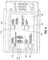
- Figure 4 is a screen display of copy quality adjustment programming in accordance with the present invention; and
- Figure 5 is a flow chart illustrating the programming of copy quality adjustment in accordance with the present invention.
- FIG. 1 shows one example of the overall construction of a color copying machine to which this invention is applied. A typical color copying machine to which this invention is applied is formed with the
base machine 30, composed of aplaten glass plate 31, which carries the original sheet thereon, an image input terminal (IIT) 32, an electricalcontrol system container 33, the image output terminal (IOT) 34, apaper tray 35, and a user interface (U/I) 36 and also, as optional items, anediting pad 61, an automatic document feeder (ADF) 62, asorter 63, and a film projector (F/P) 64. - Electrical hardware is necessary for performing the control of the IIT, IOT, U/I, etc. mentioned above, and a plural number of boards for control of each of the processing units, such as the IIT, IPS, U/I, F/P, and so forth, which perform the image-forming process for the output signals from the IIT, and these are accommodated further in the electrical
control system container 33. - The
IIT 32 is composed of animaging unit 37, thewire 38 for driving the said unit, thedriving pulley 39, and so forth, andIIT 32 reads a color original sheet for each of the primary colors B (Blue), G (Green), and R (Red) by means of a CCD line sensor and a color filter provided inside theimaging unit 37, converts the data so obtained into digital image signals and then outputs the signals to the IPS. - In the IPS, the B, G, and R signals mentioned above are transformed into the primary colors of the toner, i.e. Y(Yellow), C(Cyan), M(Magenta), and K(Black), and then, with various data processing being applied to the data so obtained for the purpose of enhancing the reproduction fidelity and fineness, and so forth, the IPS converts the toner signals of the process color in harmonious gradation into binary toner signals and outputs them to the IOT 34.
- The IOT 34, which is provided with a
scanner 40 and a photo-sensitive material belt 41, converts the image signals from the above-mentioned IPS into optical signals in thelaser output part 40a and forms a latent image corresponding to the image on the original sheet on thephotosensitive material belt 41 by way of thepolygon mirror 40b, thelens 40c, and thereflexive mirror 40d. Thephotosensitive material belt 41, which is driven by thedriving pulley 41a, has a cleaner 41b, acharging unit 41c, a developingstation 41d including the individual developing devices for Y, C, M, and K, and atransfer device 41e arranged around it. And, opposite to thistransfer device 41e is provided atransfer unit 42, which takes into it the sheet that comes transported to it from thepaper tray 35 via thepaper transport channel 35a and transfers the colors in the order of Y, C, M, and K, thetransfer unit 42 being rotated four turns, for example, for full-color copying in four full colors The sheet of paper on which the image is so transferred is then transported from thetransfer unit 42 via thevacuum transport device 43 to thefixing device 45, where it is fixed, and is thereafter discharged from it. Moreover, thepaper transport channel 35a is so designed as to accept the paper fed alternatively from the SSI (Single Sheet Inserter) 35b. - The U/
I 36 is designed for use by the user for making the selections of the desired functions and for giving instructions regarding the conditions for the execution of the selected functions, and this system is provided with acolor display unit 51 and ahardware control panel 52 installed by the side of the said display unit, and it is further combined with an infraredray touch board 53, so that instructions can be given directly with the "soft buttons" on the screen. For further details reference is made to US-A-5,032,903. - With reference to Figure 2, there is illustrated in general block form, the control of the
base machine 30 shown in Figure 1. The base machine is controlled by a plurality of printed wiring boards interconnected to a common channel orbus 98. For purposes of explanation, four printed wiring boards,boards wiring board 108 being the control for theuser interface 36 and the remaining printed wiring boards providing control for predetermined systems and components of thebase machine 30. It should be understood that the number of printed wiring boards and the manner of interconnection is merely a design choice and any other suitable control scheme for controlling the base machine is contemplated within the scope of this invention. It should also be noted that one of the printed wiring boards, for example,board 102 could be the master control for the other printed wiring boards or that there could be any number of master/slave relationships of the control boards or distributed control of the various functions of the base machine. - For purposes of understanding the present invention, it is only necessary to know that the
base machine 30 has control software resident on several printed circuit boards that communicate with each other using a common network, and that thebase machine 30 has auser interface 36 that is controlled by software that is also part of the common network, illustrated by printedcircuit board 108. Figure 3 is merely a simplified version of thecolor display unit 51, andhardware control panel 52 of theuser interface 36 illustrating various soft control buttons such as full color, auto paper, and auto reduction/enlargement. - In accordance with the present invention, with reference to Figure 4, there is a technique to program or preset the time and frequency of machine quality adjustments to prevent the copier from performing the CQ adjusts at an inconvenient time. These machine adjustments are normally routine and, in a preferred embodiment, a standard machine analysis is performed. However, it is within the scope of the present invention that different levels of machine analysis can be specified. That is, a more in depth analysis of specific components of the machine can be performed at predetermined times different from the routine analysis.
- The customer enters the CQ adjust mode by activating a suitable button, such as
button 53 shown in Figure 3 Alternatively,button 53 could be a soft button suitably displayed onscreen 51 within an appropriate screen frame for setting various default conditions or providing access to various operator software tools Upon pushingbutton 53, a suitable frame or screen such asscreen 86 displays various options. - The
ENABLE FEATURE button 110 andDISABLE FEATURE button 112 provide the operator with the means to enable or disable the automatic CQ adjust feature. CURRENT SELECTED TIME slots, illustrated at 114, displays the current programmed times the customer has previously entered to set the time for the CQ adjust to be performed. Preferably, there is no limit the the number of times or slots that can be selected, although 5 are shown here as an example. Clearly, if no times have been preset, thedisplay area 114 will be blank. The NEXT SELECTEDTIME SLOT button 116 allows the operator to scroll through the time slots. Currently the 12:00PM time slot 118 is selected. By striking the NEXTSELECTED TIME button 116, the 4:35 PM time slot would be highlighted. - The
DELETE TIME button 120 provides the operator with the mechanism to delete the current highlighted time slot. In other words, as illustrated in Figure 4, upon striking theDELETE TIME button 120, the operator would eliminate the 12:00PM time slot 118 from the screen. TheCHANGE TIME button 122 allows the operator to change the time for the particular time slot that is highlighted. After selecting theCHANGE TIME button 122 , the operator can enter in the desired time. The desired time is entered using any suitable keyboard with numerals such askeys 53 shown in Figure 2. It is also within the scope of the present invention to provide suitable message prompts on the display screen to assist the operator in CQ adjust programming. For example, a suitable prompt to "enter in the desired time" would be appropriate after the operator has hit theCHANGE TIME button 122. - There is also provided an EXIT CQ
TIME PROGRAMMING button 124. Upon pressing this button, a save all changes or store all changes operation is executed. In a preferred embodiment, all preset times are stored in suitable nonvolatile memory (NVM) such asNVM 109 shown in figure 2. In addition to saving or storing the preset times, the EXIT CQTIME PROGRAMMING button 124 initiates the exit from the CQ adjust mode and returns the operator to a suitable frame onscreen 51 such as any well known Walk-up frame. - It should be noted that the CURRENT SELECTED TIME slots, illustrated at 114, are listed in chronological order. In a preferred embodiment, by changing a current time slot such as 118, the list will be re-displayed in chronological order after it has been entered. To add an additional time slot to the CURRENT SELECTED TIME slots, the operator scrolls to the next unused slot by using the NEXT SELECTED
TIME SLOT button 116 and selects theCHANGE TIME button 122 to enter in the desired time. - It should be noted that a copy quality adjustment, even in a relatively complex color machine, may be approximately two minutes. Yet, a two minute interruption in the middle of a job or even between jobs is often unsatisfactory to an operator and the general operation of a print machine or reproduction center. It should also be noted that the adjustments can be adapted to a wide variety of specific machines or to a machine environment such as a plurality of different machines on a network. Machine performance is measured against standards of expected quality. Obviously, these standards can vary from machine to machine. It should be noted, however, that the scope of the instant invention is applicable to any machine environment and to any type of reproduction operation The essence of the invention is that the periodic analysis of copy quality and adjustment of the machine based upon copy quality is programmable and can be preset to satisfy the requirements of a particular machine or operating environment. As shown in Figure 4, an optional CQ adjust
button 128 is in phantom. It is within the scope of the present invention also to invoke alternative CQ adjust procedures For example, the operator may specify an extensive adjustment procedure at night and more routine adjustments during the day. - With reference to Figure 5, there is illustrated a typical scenario for copy quality programming in accordance with the present invention. As illustrated at
block 130, there is an enable copy quality adjust. As stated above, this is any suitable switch or button to place the machine control into a copy quality adjust status. In a copy quality adjust status, the operator would be provided with a screen display such as shown in Figure 4, displaying at 114 preset times in certain time slots or blank time slots. At 132 the operator scrolls withbutton 116 through the time slots highlighting each time slot as illustrated at 118. - At
decision block 134, assuming a time has already been preset in the time slot, the operator would make a decision whether or not to delete the time Tx in a given slot TSn If the operator determines to delete the particular time Tx from the time slot TSn the operator merely strikes thedelete time button 120 to delete the time as illustrated at 136. If on the other hand, the operator does not want to delete the time Tx but rather change the time in the time slot T Sn this decision is illustrated atblock 138. At decision blocks 140 and 144, the operator determines which mode of copy quality adjust is to be effected by the time change. As discussed above, the scope of the present invention is to cover more than one mode of copy quality adjust. For example, there may be one mode of copy quality adjust that is less extensive and thorough and, therefore, more properly performed at more frequent intervals. If, the operator selects copy adjustmode 1, then as illustrated atblock 146, the operator changes the time in time slot TSn to Ty. On the other hand, atblock 144, the operator indicates copy adjustmode # 2 by striking asuitable mode # 2 button such as shown at 128 for a new time Ty for time slot TSn - After a determination for a particular time slot has been determined, for example, to delete the time, to change the time, or to leave the time slot unchanged, there is a
decision block 148 as to whether or not the last time slot has been scrolled. If not, as illustrated atblock 152 there is a scroll to the next time slot and the cycle is repeated as necessary to complete changes for each of the desired time slots. It should be noted that at any time in the cycle, by strikingbutton 124, the operator can exit the CQ time programming state (block 150) and return to machine operation. - By providing the customer with the option to select the times and even the type of machine copy quality check, the customer achieves the maximum productivity with the minimum impact on machine performance. Typical scheduled copy quality adjust times might be during lunch hours, break hours, or during times of known inactivity. It is also within the scope of the present invention to delay or hold off a performance of a copy quality check for a given period or "window" of time to conform with the scheduled time, thus, even though a copy quality check may determine that copy quality has deteriorated to the point where a copy quality adjustment is almost immediately necessary, it still may be possible to delay the copy quality check for a certain period of time. For example, if at 2:15 PM the machine determines that a copy quality check was necessary, but the customer had programmed a copy quality check for 10:15 AM, 12:00 PM, and 2:30 PM, the machine could delay a copy quality check until the 2:30 scheduled time.
Claims (10)
- A method of presetting events for checking in an image processing apparatus having image processing components for forming images on a medium, and a controller for directing the operation of the image processing components including a user interface and a monitoring element for checking the operation of the apparatus in one or more modes, the method comprising:
providing a plurality of presetting events options,
selecting one or more presetting event options to set one or more options for checking the apparatus by the monitoring element,
storing the selected event options for checking of the apparatus in the controller, and
responding to said selected event option or options to activate the monitoring element for checking the apparatus. - The method of claim 1 wherein the apparatus is checked for image quality standards.
- The method of claim 1 wherein an event is a machine usage indicator.
- The method of claim 1 wherein an event is a time setting.
- The method of claim 1 including the step of scrolling the event options on a screen display.
- The method of claim 1 wherein an event is an image processing threshold.
- A method of automatically adjusting the quality of an image processing apparatus depending upon the deviation of the image processing apparatus from image quality standards, the apparatus having image processing components for forming images on a medium, and a controller for directing the operation of the image processing components including an image quality monitoring element for checking the operation of the apparatus in relation to image quality standards, the method comprising:
recognizing a deviation from the image quality standards,
pre-determining at least one time to respond to said deviation from the image quality standards, and
providing a quality adjustment to the image processing apparatus in response to said deviation from the image quality standards at said time or times. - A method of presetting the initiation of the checking of an image processing apparatus in relation to image quality standards by an image quality monitoring element, the apparatus having image processing components for forming images on a medium, and a controller for directing the operation of the image processing components including a user interface with display screen, the method comprising:
providing a frame on the display screen having one or more presetting options,
selecting one or more of the presetting options to set one or more initiations of the checking of the apparatus by the image quality monitoring element,
storing said one or more initiations of the checking of the apparatus by the image quality monitoring element in the controller,
responding to said one or more initiations to activate the image quality monitoring element to initiate the checking of the apparatus in relation to image quality standards, and
adjusting the image processing components for forming images on a medium in response to the checking of the apparatus in relation to image quality standards. - The method of claim 8 wherein the or each initiation of the checking of the apparatus is a time of day setting.
- An image processing apparatus having image processing components for forming images on a medium, a controller for directing the operation of the image processing components including a user interface and an image quality monitoring element for checking the operation of the apparatus, means for providing a plurality of presetting times, a selector to set a plurality of times for checking the apparatus by the image quality monitoring element, means for storing the selected plurality of times in the controller, and means for responding to said selected plurality of times to activate the image quality monitoring element for checking the apparatus.
Applications Claiming Priority (2)
| Application Number | Priority Date | Filing Date | Title |
|---|---|---|---|
| US64475 | 1993-05-21 | ||
| US08/064,475 US5394251A (en) | 1993-05-21 | 1993-05-21 | Customer schedulable machine quality adjust |
Publications (3)
| Publication Number | Publication Date |
|---|---|
| EP0631202A2 true EP0631202A2 (en) | 1994-12-28 |
| EP0631202A3 EP0631202A3 (en) | 1997-03-19 |
| EP0631202B1 EP0631202B1 (en) | 2002-05-08 |
Family
ID=22056247
Family Applications (1)
| Application Number | Title | Priority Date | Filing Date |
|---|---|---|---|
| EP94303624A Expired - Lifetime EP0631202B1 (en) | 1993-05-21 | 1994-05-20 | Image quality adjustment method and an image processing apparatus |
Country Status (3)
| Country | Link |
|---|---|
| US (1) | US5394251A (en) |
| EP (1) | EP0631202B1 (en) |
| DE (1) | DE69430554T2 (en) |
Cited By (3)
| Publication number | Priority date | Publication date | Assignee | Title |
|---|---|---|---|---|
| GB2305057A (en) * | 1995-08-24 | 1997-03-26 | Lg Electronics Inc | Controlling facsimile apparatus operating modes |
| FR2779309A1 (en) * | 1998-05-26 | 1999-12-03 | Sagem | OPTICAL DOCUMENT ANALYSIS PROCESS |
| EP1289251A1 (en) * | 2001-08-28 | 2003-03-05 | Xerox Corporation | Versatile system for creating test images in a digital printing apparatus |
Families Citing this family (11)
| Publication number | Priority date | Publication date | Assignee | Title |
|---|---|---|---|---|
| US5604858A (en) * | 1992-08-10 | 1997-02-18 | International Business Machines Corporation | Method and system for apparent direct editing of fixed display elements within a data processing system |
| JP3043552B2 (en) * | 1993-10-04 | 2000-05-22 | シャープ株式会社 | Image stabilization device for electrophotographic equipment |
| JP3408119B2 (en) * | 1996-08-23 | 2003-05-19 | キヤノン株式会社 | Image processing apparatus and method, and recording medium |
| JPH1115216A (en) * | 1997-06-26 | 1999-01-22 | Canon Inc | Image processor, control method therefor and record medium |
| NL1007875C2 (en) * | 1997-12-23 | 1999-06-24 | Oce Tech Bv | Reproduction device. |
| JP2000132010A (en) * | 1998-10-21 | 2000-05-12 | Ricoh Co Ltd | Image forming device |
| US6157221A (en) * | 1999-03-23 | 2000-12-05 | Northrop Grumman Corporation | Three input comparator |
| USD425109S (en) * | 1999-06-29 | 2000-05-16 | Xerox Corporation | User interface for an electrostatographic machine |
| US7859691B2 (en) * | 2006-06-02 | 2010-12-28 | Xerox Corporation | Printer having Bi-level operational modes |
| JP5088541B2 (en) * | 2007-06-11 | 2012-12-05 | ソニー株式会社 | Information processing apparatus and method, and program |
| US9440814B1 (en) * | 2015-12-15 | 2016-09-13 | Xerox Corporation | Method and apparatus for mitigating sheet wrinkle resulting from decurler contamination |
Citations (3)
| Publication number | Priority date | Publication date | Assignee | Title |
|---|---|---|---|---|
| US5138377A (en) * | 1991-05-23 | 1992-08-11 | Xerox Corporation | Internal expert system to aid in servicing |
| US5182599A (en) * | 1990-08-08 | 1993-01-26 | Minolta Camera Kabushiki Kaisha | Multi-color image forming apparatus and method of setting image data for same |
| US5245389A (en) * | 1990-11-27 | 1993-09-14 | Minolta Camera Kabushiki Kaisha | Image forming apparatus |
Family Cites Families (3)
| Publication number | Priority date | Publication date | Assignee | Title |
|---|---|---|---|---|
| JPH0783412B2 (en) * | 1991-02-12 | 1995-09-06 | 富士ゼロックス株式会社 | Recording device management system |
| US5210571A (en) * | 1991-09-26 | 1993-05-11 | Xerox Corporation | System for servicing electronic printers and printing systems |
| US5229815A (en) * | 1992-09-04 | 1993-07-20 | Xerox Corporation | Automatic machine quality adjust restart after premature interruption |
-
1993
- 1993-05-21 US US08/064,475 patent/US5394251A/en not_active Expired - Lifetime
-
1994
- 1994-05-20 EP EP94303624A patent/EP0631202B1/en not_active Expired - Lifetime
- 1994-05-20 DE DE69430554T patent/DE69430554T2/en not_active Expired - Lifetime
Patent Citations (3)
| Publication number | Priority date | Publication date | Assignee | Title |
|---|---|---|---|---|
| US5182599A (en) * | 1990-08-08 | 1993-01-26 | Minolta Camera Kabushiki Kaisha | Multi-color image forming apparatus and method of setting image data for same |
| US5245389A (en) * | 1990-11-27 | 1993-09-14 | Minolta Camera Kabushiki Kaisha | Image forming apparatus |
| US5138377A (en) * | 1991-05-23 | 1992-08-11 | Xerox Corporation | Internal expert system to aid in servicing |
Cited By (4)
| Publication number | Priority date | Publication date | Assignee | Title |
|---|---|---|---|---|
| GB2305057A (en) * | 1995-08-24 | 1997-03-26 | Lg Electronics Inc | Controlling facsimile apparatus operating modes |
| GB2305057B (en) * | 1995-08-24 | 1998-06-10 | Lg Electronics Inc | Controlling facsimile apparatus |
| FR2779309A1 (en) * | 1998-05-26 | 1999-12-03 | Sagem | OPTICAL DOCUMENT ANALYSIS PROCESS |
| EP1289251A1 (en) * | 2001-08-28 | 2003-03-05 | Xerox Corporation | Versatile system for creating test images in a digital printing apparatus |
Also Published As
| Publication number | Publication date |
|---|---|
| EP0631202B1 (en) | 2002-05-08 |
| EP0631202A3 (en) | 1997-03-19 |
| US5394251A (en) | 1995-02-28 |
| DE69430554D1 (en) | 2002-06-13 |
| DE69430554T2 (en) | 2002-08-29 |
Similar Documents
| Publication | Publication Date | Title |
|---|---|---|
| US5414494A (en) | Automatic call to selected remote operators in response to predetermined machine conditions | |
| EP0631202B1 (en) | Image quality adjustment method and an image processing apparatus | |
| US5305055A (en) | Automatic call to selected remote operators in response to predetermined machine conditions | |
| US5198909A (en) | Driving apparatus and method for scanning system for use in image recording apparatus | |
| US8077340B2 (en) | Image forming apparatus | |
| US5121195A (en) | Gray balance control system | |
| JPH02244868A (en) | Self-diagnostic system for image reader | |
| JPH02208646A (en) | Density correcting system for film image reader | |
| EP0891073B1 (en) | Image processing apparatus and image processing method | |
| EP0301459A2 (en) | Image forming apparatus | |
| JPH03191655A (en) | Self-diagnostic system for recording device | |
| JP2000003241A (en) | Display device | |
| US5229815A (en) | Automatic machine quality adjust restart after premature interruption | |
| US5343275A (en) | Job programming during machine quality adjust | |
| US20040145764A1 (en) | Image displaying device and image forming device | |
| JP2000047532A (en) | Image forming device, method for controlling display thereof, and recording medium | |
| US5734799A (en) | Image forming apparatus | |
| US5305058A (en) | Progressive levels of automatic machine quality adjust | |
| US5313468A (en) | Self-diagnosing system for recording apparatus | |
| JP2003150009A (en) | Image forming apparatus | |
| JP3349805B2 (en) | Image forming device | |
| JPH0618424B2 (en) | Image processing device | |
| JP3148785B2 (en) | Copy machine with trial copy function | |
| JPH02275938A (en) | Color cast correction system for film image reader | |
| JP3413172B2 (en) | Image forming apparatus and control method thereof |
Legal Events
| Date | Code | Title | Description |
|---|---|---|---|
| PUAI | Public reference made under article 153(3) epc to a published international application that has entered the european phase |
Free format text: ORIGINAL CODE: 0009012 |
|
| AK | Designated contracting states |
Kind code of ref document: A2 Designated state(s): DE FR GB |
|
| PUAL | Search report despatched |
Free format text: ORIGINAL CODE: 0009013 |
|
| AK | Designated contracting states |
Kind code of ref document: A3 Designated state(s): DE FR GB |
|
| 17P | Request for examination filed |
Effective date: 19970919 |
|
| 17Q | First examination report despatched |
Effective date: 19971014 |
|
| GRAG | Despatch of communication of intention to grant |
Free format text: ORIGINAL CODE: EPIDOS AGRA |
|
| RTI1 | Title (correction) |
Free format text: IMAGE QUALITY ADJUSTMENT METHOD AND AN IMAGE PROCESSING APPARATUS |
|
| GRAG | Despatch of communication of intention to grant |
Free format text: ORIGINAL CODE: EPIDOS AGRA |
|
| GRAH | Despatch of communication of intention to grant a patent |
Free format text: ORIGINAL CODE: EPIDOS IGRA |
|
| REG | Reference to a national code |
Ref country code: GB Ref legal event code: IF02 |
|
| GRAG | Despatch of communication of intention to grant |
Free format text: ORIGINAL CODE: EPIDOS AGRA |
|
| GRAH | Despatch of communication of intention to grant a patent |
Free format text: ORIGINAL CODE: EPIDOS IGRA |
|
| GRAA | (expected) grant |
Free format text: ORIGINAL CODE: 0009210 |
|
| AK | Designated contracting states |
Kind code of ref document: B1 Designated state(s): DE FR GB |
|
| REF | Corresponds to: |
Ref document number: 69430554 Country of ref document: DE Date of ref document: 20020613 |
|
| ET | Fr: translation filed | ||
| PLBE | No opposition filed within time limit |
Free format text: ORIGINAL CODE: 0009261 |
|
| STAA | Information on the status of an ep patent application or granted ep patent |
Free format text: STATUS: NO OPPOSITION FILED WITHIN TIME LIMIT |
|
| 26N | No opposition filed |
Effective date: 20030211 |
|
| REG | Reference to a national code |
Ref country code: GB Ref legal event code: 746 Effective date: 20050404 |
|
| PGFP | Annual fee paid to national office [announced via postgrant information from national office to epo] |
Ref country code: DE Payment date: 20130423 Year of fee payment: 20 Ref country code: GB Payment date: 20130424 Year of fee payment: 20 |
|
| PGFP | Annual fee paid to national office [announced via postgrant information from national office to epo] |
Ref country code: FR Payment date: 20130626 Year of fee payment: 20 |
|
| REG | Reference to a national code |
Ref country code: DE Ref legal event code: R071 Ref document number: 69430554 Country of ref document: DE |
|
| REG | Reference to a national code |
Ref country code: GB Ref legal event code: PE20 Expiry date: 20140519 |
|
| PG25 | Lapsed in a contracting state [announced via postgrant information from national office to epo] |
Ref country code: GB Free format text: LAPSE BECAUSE OF EXPIRATION OF PROTECTION Effective date: 20140519 |
|
| PG25 | Lapsed in a contracting state [announced via postgrant information from national office to epo] |
Ref country code: DE Free format text: LAPSE BECAUSE OF EXPIRATION OF PROTECTION Effective date: 20140521 |