EP0630996A2 - Skin-core high thermal bond strength fiber on melt spin system - Google Patents
Skin-core high thermal bond strength fiber on melt spin system Download PDFInfo
- Publication number
- EP0630996A2 EP0630996A2 EP94304570A EP94304570A EP0630996A2 EP 0630996 A2 EP0630996 A2 EP 0630996A2 EP 94304570 A EP94304570 A EP 94304570A EP 94304570 A EP94304570 A EP 94304570A EP 0630996 A2 EP0630996 A2 EP 0630996A2
- Authority
- EP
- European Patent Office
- Prior art keywords
- spinnerette
- heating
- polymer composition
- process according
- polymer
- Prior art date
- Legal status (The legal status is an assumption and is not a legal conclusion. Google has not performed a legal analysis and makes no representation as to the accuracy of the status listed.)
- Granted
Links
Images


Classifications
-
- D—TEXTILES; PAPER
- D01—NATURAL OR MAN-MADE THREADS OR FIBRES; SPINNING
- D01D—MECHANICAL METHODS OR APPARATUS IN THE MANUFACTURE OF ARTIFICIAL FILAMENTS, THREADS, FIBRES, BRISTLES OR RIBBONS
- D01D5/00—Formation of filaments, threads, or the like
- D01D5/28—Formation of filaments, threads, or the like while mixing different spinning solutions or melts during the spinning operation; Spinnerette packs therefor
- D01D5/30—Conjugate filaments; Spinnerette packs therefor
- D01D5/34—Core-skin structure; Spinnerette packs therefor
-
- D—TEXTILES; PAPER
- D01—NATURAL OR MAN-MADE THREADS OR FIBRES; SPINNING
- D01F—CHEMICAL FEATURES IN THE MANUFACTURE OF ARTIFICIAL FILAMENTS, THREADS, FIBRES, BRISTLES OR RIBBONS; APPARATUS SPECIALLY ADAPTED FOR THE MANUFACTURE OF CARBON FILAMENTS
- D01F11/00—Chemical after-treatment of artificial filaments or the like during manufacture
- D01F11/04—Chemical after-treatment of artificial filaments or the like during manufacture of synthetic polymers
-
- D—TEXTILES; PAPER
- D01—NATURAL OR MAN-MADE THREADS OR FIBRES; SPINNING
- D01D—MECHANICAL METHODS OR APPARATUS IN THE MANUFACTURE OF ARTIFICIAL FILAMENTS, THREADS, FIBRES, BRISTLES OR RIBBONS
- D01D4/00—Spinnerette packs; Cleaning thereof
- D01D4/02—Spinnerettes
-
- D—TEXTILES; PAPER
- D01—NATURAL OR MAN-MADE THREADS OR FIBRES; SPINNING
- D01D—MECHANICAL METHODS OR APPARATUS IN THE MANUFACTURE OF ARTIFICIAL FILAMENTS, THREADS, FIBRES, BRISTLES OR RIBBONS
- D01D5/00—Formation of filaments, threads, or the like
- D01D5/08—Melt spinning methods
-
- D—TEXTILES; PAPER
- D01—NATURAL OR MAN-MADE THREADS OR FIBRES; SPINNING
- D01D—MECHANICAL METHODS OR APPARATUS IN THE MANUFACTURE OF ARTIFICIAL FILAMENTS, THREADS, FIBRES, BRISTLES OR RIBBONS
- D01D5/00—Formation of filaments, threads, or the like
- D01D5/08—Melt spinning methods
- D01D5/088—Cooling filaments, threads or the like, leaving the spinnerettes
-
- D—TEXTILES; PAPER
- D01—NATURAL OR MAN-MADE THREADS OR FIBRES; SPINNING
- D01F—CHEMICAL FEATURES IN THE MANUFACTURE OF ARTIFICIAL FILAMENTS, THREADS, FIBRES, BRISTLES OR RIBBONS; APPARATUS SPECIALLY ADAPTED FOR THE MANUFACTURE OF CARBON FILAMENTS
- D01F6/00—Monocomponent artificial filaments or the like of synthetic polymers; Manufacture thereof
- D01F6/02—Monocomponent artificial filaments or the like of synthetic polymers; Manufacture thereof from homopolymers obtained by reactions only involving carbon-to-carbon unsaturated bonds
- D01F6/04—Monocomponent artificial filaments or the like of synthetic polymers; Manufacture thereof from homopolymers obtained by reactions only involving carbon-to-carbon unsaturated bonds from polyolefins
- D01F6/06—Monocomponent artificial filaments or the like of synthetic polymers; Manufacture thereof from homopolymers obtained by reactions only involving carbon-to-carbon unsaturated bonds from polyolefins from polypropylene
-
- D—TEXTILES; PAPER
- D04—BRAIDING; LACE-MAKING; KNITTING; TRIMMINGS; NON-WOVEN FABRICS
- D04H—MAKING TEXTILE FABRICS, e.g. FROM FIBRES OR FILAMENTARY MATERIAL; FABRICS MADE BY SUCH PROCESSES OR APPARATUS, e.g. FELTS, NON-WOVEN FABRICS; COTTON-WOOL; WADDING ; NON-WOVEN FABRICS FROM STAPLE FIBRES, FILAMENTS OR YARNS, BONDED WITH AT LEAST ONE WEB-LIKE MATERIAL DURING THEIR CONSOLIDATION
- D04H1/00—Non-woven fabrics formed wholly or mainly of staple fibres or like relatively short fibres
- D04H1/40—Non-woven fabrics formed wholly or mainly of staple fibres or like relatively short fibres from fleeces or layers composed of fibres without existing or potential cohesive properties
- D04H1/54—Non-woven fabrics formed wholly or mainly of staple fibres or like relatively short fibres from fleeces or layers composed of fibres without existing or potential cohesive properties by welding together the fibres, e.g. by partially melting or dissolving
-
- D—TEXTILES; PAPER
- D04—BRAIDING; LACE-MAKING; KNITTING; TRIMMINGS; NON-WOVEN FABRICS
- D04H—MAKING TEXTILE FABRICS, e.g. FROM FIBRES OR FILAMENTARY MATERIAL; FABRICS MADE BY SUCH PROCESSES OR APPARATUS, e.g. FELTS, NON-WOVEN FABRICS; COTTON-WOOL; WADDING ; NON-WOVEN FABRICS FROM STAPLE FIBRES, FILAMENTS OR YARNS, BONDED WITH AT LEAST ONE WEB-LIKE MATERIAL DURING THEIR CONSOLIDATION
- D04H3/00—Non-woven fabrics formed wholly or mainly of yarns or like filamentary material of substantial length
- D04H3/08—Non-woven fabrics formed wholly or mainly of yarns or like filamentary material of substantial length characterised by the method of strengthening or consolidating
- D04H3/16—Non-woven fabrics formed wholly or mainly of yarns or like filamentary material of substantial length characterised by the method of strengthening or consolidating with bonds between thermoplastic filaments produced in association with filament formation, e.g. immediately following extrusion
-
- Y—GENERAL TAGGING OF NEW TECHNOLOGICAL DEVELOPMENTS; GENERAL TAGGING OF CROSS-SECTIONAL TECHNOLOGIES SPANNING OVER SEVERAL SECTIONS OF THE IPC; TECHNICAL SUBJECTS COVERED BY FORMER USPC CROSS-REFERENCE ART COLLECTIONS [XRACs] AND DIGESTS
- Y10—TECHNICAL SUBJECTS COVERED BY FORMER USPC
- Y10S—TECHNICAL SUBJECTS COVERED BY FORMER USPC CROSS-REFERENCE ART COLLECTIONS [XRACs] AND DIGESTS
- Y10S425/00—Plastic article or earthenware shaping or treating: apparatus
- Y10S425/013—Electric heat
Definitions
- the present invention relates to synthetic fibers, especially synthetic fibers used in the manufacture of nonwoven fabrics.
- the present invention relates to processes and apparatus for the production of polymer fibers and filaments. More specifically, the present invention relates to skin-core fibers produced using melt spin processes, including short spin and long spin processes, and to articles incorporating these skin-core fibers.
- the production of polymer fibers and filaments usually involves the use of a mix of a single polymer with nominal amounts of stabilizers and pigments.
- the mix is melt extruded into fibers and fibrous products using conventional commercial processes.
- Non-woven fabrics are typically made by making a web of the fibers, and then thermally bonding the fibers together where they meet. More specifically, staple fibers are converted into non-woven fabrics using, for example, a carding machine, and the carded fabric is thermally bonded.
- the thermal bonding can be achieved using various heating techniques, including heating with heated rollers and heating through the use of ultrasonic welding.
- thermally bonded non-woven fabrics exhibit good loft and softness properties, but less than optimal cross-directional strength, and less than optimal cross-directional strength in combination with high elongation.
- the strength of the thermally bonded non-woven fabrics depends upon the orientation of the fibers and the inherent strength of the bond points.
- thermally bondable fibers that can achieve superior cross-directional strength, elongation and toughness properties in combination with fabric uniformity and loftiness.
- 07/474,897, filed February 5, 1990, 07/683,635, filed April 11, 1991, 07/836,438, filed February 18, 1992, and 07/939,857, filed September 2, 1992 are directed to processes for preparing polypropylene containing fibers by extruding polypropylene containing material having a molecular weight distribution of at least about 5.5 to form hot extrudate having a surface, with quenching of the hot extrudate in an oxygen containing atmosphere being controlled so as to effect oxidative chain scission degradation of the surface.
- the quenching of the hot extrudate in an oxygen containing atmosphere can be controlled so as to maintain the temperature of the hot extrudate above about 250°C for a period of time to obtain oxidative chain scission degradation of the surface.
- the resulting fiber By controlling the quenching to obtain oxidative chain scission degradation of the surface, the resulting fiber essentially contains a plurality of zones, defined by different characteristics including differences in melt flow rate, molecular weight, melting point, birefringence, orientation and crystallinity.
- the fiber produced by the delayed quench process includes an inner zone identified by a substantial lack of oxidative polymeric degradation, an outer zone of a high concentration of oxidative chain scission degraded polymeric material, and an intermediate zone identified by an inside-to-outside increase in the amount of oxidative chain scission polymeric degradation.
- the quenching of the hot extrudate in an oxygen containing atmosphere can be controlled so as to obtain a fiber having a decreasing weight average molecular weight towards the surface of the fiber, and an increasing melt flow rate towards the surface of the fiber.
- the fiber comprises an inner zone having a weight average molecular weight of about 100,000 to 450,000 grams/mole, an outer zone, including the surface of the fiber, having a weight average molecular weight of less than about 10,000 grams/mole, and an intermediate zone positioned between the inner zone and the outer zone having a weight average molecular weight and melt flow rate intermediate the inner zone and the outer zone.
- the inner, core zone has a melting point and orientation that is higher than the outer surface zone.
- U.S. Application Serial Nos. 08/003,696, filed January 13, 1993, 07/943,190, filed September 11, 1992, and 07/818,772, filed January 13, 1992, to Gupta et al. are directed to processes for spinning polypropylene fibers, and the resulting fibers and products made from such fibers.
- the processes of the Gupta et al. applications include melt spinning a polypropylene composition having a broad molecular weight distribution through a spinnerette to form molten fibers, and quenching the molten fibers to obtain thermally bondable polypropylene fibers.
- these processes include the older two-step "long spin” process and the newer one-step “short spin” process.
- the long spin process involves first melt-extruding fibers at typical spinning speeds of 500 to 3000 meters per minute, and more usually depending on the polymer to be spun from 500 to 1500 meters per minute. Additionally, in a second step usually run at 100 to 250 meters per minute, these fibers are drawn, crimped, and cut into staple fiber.
- the one-step short spin process involves conversion from polymer to staple fibers in a single step where typical spinning speeds are in the range of 50 to 200 meters per minute.
- the productivity of the one-step process is increased with the use of about 5 to 20 times the number of capillaries in the spinnerette compared to that typically used in the long spin process.
- spinnerettes for a typical commercial "long spin” process would include approximately 50-4,000, preferably approximately 3,000-3,500 capillaries
- spinnerettes for a typical commercial "short spin” process would include approximately 500 to 100,000 capillaries preferably, about 30,000-70,000 capillaries.
- Typical temperatures for extrusion of the spin melt in these processes are about 250-325°C.
- the numbers of capillaries refers to the number of filaments being extruded, and usually not the number of capillaries in the spinnerette.
- the short spin process for manufacture of polypropylene fiber is significantly different from the conventional long spin process in terms of the quenching conditions needed for spin continuity.
- quench air velocity is required in the range of about 3,000-8,000 ft/minute to complete fiber quenching within one inch below the spinnerette face.
- a lower quench air velocity in the range of 300 to 500 ft./minute is used.
- Killoran In describing the processing of polypropylene, Killoran teaches that the softening temperature of polypropylene is within the range from 168°C to 170°C, and at this temperature the material becomes semi-plastic and sticky. Killoran further teaches that the temperature required for filtering and extrusion of polypropylene may be as high as 280°C, so that the temperature of the polypropylene is increased during the passage through perforations in the block from approximately 170°C to 270°C, or 280°C, that is, there is about 100°C rise from the initial softening at the entrance to the block to the molten condition at the outlet of the block.
- Killoran are limited to heating of the polymer from a solid condition to a molten condition to achieve a reduced amount of time that the polymer is in a molten condition, as well as to the prevent polymer in the molten condition from contacting moving elements.
- U.S. Patent No. 3,437,725 to Pierce which is hereby incorporated by reference in its entirety, is directed to the melt-spinning of synthetic polymers, including polypropylene.
- the spinnerette is designed so as to enable the use of polymers having higher melt viscosities, either from high molecular weight polymers or from polymers with stiff chain structures.
- the spinnerette of Pierce is designed so as to permit the spinning of polymer having a high melt viscosity without degrading the polymer.
- Pierce passes the molten polymer through the filter holder at an initial temperature within a temperature range below that at which significant polymer degradation will occur, passes the polymer into a plurality of passages, each of which leads to a different spinning capillary in the spinnerette plate and has an entrance temperature within the initial temperature range, heats the spinnerette plate to increase the temperature along the passages from the temperature at the entrance to a temperature at least 60°C higher at the spinning capillary, and extrudes the polymer from the spinning capillary after a maximum of 4 seconds of travel through the heated passage.
- the quenching of Pierce is performed using inert gas and the process is accomplished using a long spin, two step process wherein the filaments are initially spun, and subsequently drawn.
- the objects of the present invention can be obtained by providing a process for spinning polymer filaments, comprising feeding a polymer composition to at least one spinnerette; heating the polymer composition at a location at or adjacent to the at least one spinnerette so as to heat the polymer composition to a sufficient temperature to obtain a skin-core filament structure upon quenching in an oxidative atmosphere; extruding the heated polymer composition through the at least one spinnerette to form molten filaments; and immediately quenching the molten filaments in an oxidative atmosphere, as the molten filaments are extruded, to effect oxidative chain scission degradation of at least a surface of the molten filaments to obtain filaments having a skin-core structure.
- the objects of the present invention are also achieved by providing a process for spinning polymer filaments, comprising feeding a polymer composition to at least one spinnerette; heating the polymer composition at a location at or adjacent to the at least one spinnerette so as to obtain sufficient heating of the polymer composition to partially degrade the polymer composition in a vicinity of the at least one spinnerette; extruding the partially degraded polymer composition through the at least one spinnerette to form molten filaments; and immediately quenching the molten filaments in an oxidative atmcsphere, as the molten filaments are extruded, to effect oxidative chain scission degradation of at least a surface of the molten filaments to obtain filaments having a skin-core structure.
- the objects of the present invention are obtained by providing a process for spinning polymer filaments, comprising feeding a polymer composition to at least one spinnerette; heating the at least one spinnerette to a temperature of at least about 230°C; extruding the heated polymer composition through the at least one spinnerette to form molten filaments; and immediately quenching the molten filaments in an oxidative atmosphere, as the molten filaments are extruded, to effect oxidative chain scission degradation of at least a surface of the molten filaments to obtain filaments having a skin-core structure.
- the objects of the present invention are obtained by providing a process for spinning polymer filaments, comprising feeding a polymer composition to at least one spinnerette; heating at least one apertured element positioned upstream of the at least one spinnerette to a temperature of at least about 250°C; extruding the heated polymer composition through the at least one apertured element and the at least one spinnerette to form molten filaments; and immediately quenching the molten filaments in an oxidative atmosphere, as the molten filaments are extruded, to effect oxidative chain scission degradation of at least a surface of the molten filaments to obtain filaments having a skin-core structure.
- the objects of the present invention are also obtainable by providing apparatus for spinning polymer filaments, and, in particular, apparatus for performing the processes of the present invention.
- apparatus for spinning polymer filaments, comprising at least one spinnerette; means for feeding a polymer composition through the at least one spinnerette to extrude molten filaments; means for heating the polymer composition at a location at or adjacent to the at least one spinnerette to obtain sufficient heating of the polymer composition to obtain a skin-core filament structure upon quenching in an oxidative atmosphere; and means for immediately quenching molten filaments of extruded polymer in an oxidative atmosphere, as the molten filaments exit the at least one spinnerette, to effect oxidative chain scission degradation of at least a surface of the molten filaments to obtain filaments having a skin-core structure.
- the apparatus for spinning polymer filaments comprises at least one spinnerette; means for feeding a polymer composition through the at least one spinnerette to extrude molten filaments; means for substantially uniformly heating the polymer composition at a location at or adjacent to the at least one spinnerette so as to obtain sufficient heating of the polymer composition to partially degrade the polymer composition in a vicinity of the at least one spinnerette; and means for immediately quenching molten filaments of extruded polymer in an oxidative atmosphere, as the molten filaments exit the at least one spinnerette, so as to effect oxidative chain scission degradation of at least a surface of the molten filaments.
- the apparatus for spinning polymer filaments comprises at least one spinnerette; means for feeding a polymer composition through the at least one spinnerette to extrude molten filaments; means for substantially uniformly heating the at least one spinnerette to a temperature of at least about 230°C; and means for quenching molten filaments of extruded polymer in an oxidative atmosphere, as the molten filaments exit the at least one spinnerette, to effect oxidative chain scission degradation of at least a surface of the molten filaments to obtain filaments having a skin-core structure.
- the apparatus for spinning polymer filaments comprises at least one spinnerette; means for feeding a polymer composition through the at least one spinnerette to extrude molten filaments; at least one apertured element positioned upstream of the at least one spinnerette; means for substantially uniformly heating the at least one apertured element to a temperature of at least about 250°C; and means for quenching molten filaments of extruded polymer in an oxidative atmosphere, as the molten filaments exit the at least one spinnerette, to effect oxidative chain scission degradation of at least a surface of the molten filaments to obtain filaments having a skin-core structure.
- the present invention is also directed to a fiber or filament comprising an inner core of polymeric material; a surface zone surrounding the inner core, the surface zone comprising oxidative chain scission degraded polymeric material, so that the inner core and the surface zone comprise a skin-core structure; and the oxidative chain scission degraded polymeric material being substantially limited to the surface zone wherein the inner core and the surface zone comprise adjacent discrete portions of the skin-core structure.
- the fiber or filament comprises an inner core of polymeric material; a surface zone having a thickness of at least about 0.5 ⁇ m, and more preferably at least about 1 ⁇ m, surrounding the inner core, the surface zone comprising oxidative chain scission degraded polymeric material, so that the inner core and the surface zone comprise a skin-core structure; and the oxidative chain scission degraded polymeric material being substantially limited to the surface zone so that the inner core and the surface zone comprise adjacent discrete portions of the skin-core structure.
- the invention is also directed to a fiber or filament comprising an inner core of polymeric material; a surface zone surrounding the inner core, the surface zone comprising oxidative chain scission degraded polymeric material, so that the inner core and the surface zone comprise a skin-core structure; and the inner core has a melt flow rate substantially equal to an average melt flow rate of the inner core and the surface zone.
- the hygienic article can comprise a diaper having an outer impermeable layer, an inner non-woven fabric layer, and an intermediate layer.
- Such hygienic products are disclosed in the above-referenced Kozulla and Gupta et al. applications, which have been incorporated by reference in their entirety herein.
- polymeric material in each of the above fibers or filaments can comprise various polymeric materials, such as polyolefins, polyesters, polyamides, polyvinyl acetates, polyvinyl alcohol and ethylene acrylic acid copolymers.
- polyolefins can comprise polyethylenes, such as low density polyethylenes, high density polyethylenes, and linear low density polyethylenes, including polyethylenes prepared by copolymerizing ethylene with at least one C3-C12 alpha-olefin; polypropylenes, such as atactic, syndiotactic, and isotactic polypropylene - including partially and fully isotactic, or at least substantially fully isotactic - polypropylenes; polybutenes; such as poly-1-butenes, poly-2-butenes, and polyisobutylenes, and poly 4-methyl-1-pentenes; polyesters can comprise poly(oxyethyleneoxyterephthaloyl); and polyamides can comprise poly(
- the heating of the polymer composition at a location at or adjacent to the at least one spinnerette comprises heating the polymer composition to a temperature of at least about 200°C, preferably at least about 220°C, and more preferably at least about 250°C.
- the extruding of the heated polymer composition comprises extruding at a temperature of at least about 200°C, preferably at least about 220°C, and more preferably at least about 250°C.
- the spinnerette can be directly heated and/or an element associated with the spinnerette, such as an apertured plate, can be heated.
- the spinnerette or the associated element is substantially uniformly heated to ensure that substantially all, and preferably all, filaments extruded through the spinnerette are capable of achieving sufficient conditions to obtain a skin-core structure.
- the heating of the spinnerette can be to a temperature of at least about 230°C, preferably at least about 250°C, and can be in the range of about 250°C to 370°C, preferably in the range of about 290°C to 360°C, and more preferably in the range of about 330°C to 360°C.
- the spinnerette according to the present invention preferably contains about 500 to 150,000 capillaries, with preferred ranges being about 30,000 to 120,000 capillaries, about 30,000 to 70,000 capillaries, and about 30,000 to 45,000 capillaries.
- These capillaries can have a cross-sectional area of about 0.02 to 0.2 mm2, preferably about 0.07 mm2, and a length of about 1 to 20 mm, preferably a length of about 1 to 5 mm, and more preferably a length of about 1.5 mm.
- the capillaries can have a recess at a lower portion, and the recess can have a cross-sectional area of about 0.05 to 0.4 mm2, preferably of about 0.3 mm2, and a length of about 0.25 mm to 2.5 mm, preferably a length of about 0.5 mm.
- the capillaries can have a tapered upper portion.
- These tapered capillaries can comprise countersunk capillaries having a total length of about 3 to 20 mm, preferably about 7-10 mm; a first cross-sectional area of about 0.03 mm2 to 0.2 mm2 at a lower portion; a maximum cross-sectional area at a surface of the at least one spinnerette of about 0.07 mm2 to 0.5 mm2, preferably about 0.2 mm2; and the countersunk capillaries taper from the maximum cross-sectional area to the first cross-sectional area at an angle of about 20° to 60°, preferably about 35° to 45°, and more preferably about 45°.
- the countersunk capillaries can include a distance between the maximum cross-sectional area to the first cross-sectional area of about 0.15 to 0.4 mm.
- the tapered capillaries can comprise counterbored, countersunk capillaries. These counterbored, countersunk capillaries can comprise an upper tapered portion having a diameter of about 0.6 mm and a length of about 0.5 mm; an upper capillary having a diameter of about 0.5 mm and a length of about 3.5 mm; a middle tapered portion having a length of about 0.1 mm; and a lower capillary having a diameter of about 0.35 mm and a length of about 1.5 mm.
- the tapered capillaries can comprise counterbored capillaries.
- These counterbored capillaries can comprise an upper capillary having a diameter of about 0.5 mm and a length of about 4 mm; a middle tapered portion having a length of about 0.1 mm; and a lower capillary having a diameter of about 0.35 mm and a length of about 2 mm.
- the apertured plate is positioned upstream of the spinnerette, preferably about 1 to 4 mm, preferably about 2 to 3 mm, and more preferably about 2.5 mm.
- the spinnerette and the apertured plate can comprise a corresponding number of capillaries and have a corresponding pattern, or there can be a different number of capillaries and/or a different pattern.
- the capillaries in the apertured plate can have a cross-sectional area that is up to about 30% larger than the cross-sectional area of capillaries in the spinnerette.
- the apertured plate preferably contains about 500 to 150,000 capillaries, with preferred ranges being about 30,000 to 120,000 capillaries, about 30,000 to 70,000 capillaries, and about 30,000 to 45,000 capillaries.
- These capillaries preferably having a cross-sectional area of about 0.03 mm2 to 0.3 mm2, more preferably of about 0.1 mm2, and a length of about 1 to 5 mm, more preferably about 1.5 mm.
- the heating of the apertured plate can be to a temperature of at least about 250°C, and can be in the range of about 250°C to 370°C, preferably in the range of about 280°C to 350°C, and more preferably in the range of about 300°C to 360°C.
- the quenching can comprise any quench with an oxidative gas that flows at a high rate of speed, preferably about 3,000 to 12,000 ft/min, more preferably about 4,000 to 9,000 ft/min, and even more preferably 5,000 to 7,000 ft/min.
- the molten filaments are immediately quenched upon being extruded.
- Examples of quenching according to the present invention include radial quenching and quenching with adjustable nozzles blowing an oxidative gas.
- the adjustable nozzles are preferably directed at a central portion of the spinnerette, and preferably have an angle of about 0° to 60° with respect to a plane passing through the surface of the spinnerette, more preferably about 10° to 60°, and can also preferably be an angle of about 0° to 45°, more preferably 0° to 25°.
- the heating can be accomplished using conduction, convection, induction, magnetic heating and/or radiation, and can be accomplished using impedance or resistance heating, inductance heating and/or magnetic heating.
- the polymer composition can comprise various spinnable polymers, including polyolefins, such as polyethylene and polypropylene, and polyesters.
- the polymer can have usual spinning temperatures temperature, i.e., the polymer melt temperature, and a narrow or broad molecular weight distribution.
- the temperature of the melt spin composition is about 200°C to 300°C, preferably 220°C to 260°C, and more preferably 230°C to 240°C
- the melt flow rate is preferably about 0.5 to 40 dg/min, with preferred ranges being 5-25 dg/min, 10-20 dg/min, 9-20 dg/min and 9-15 dg/min.
- the polypropylene composition has a broad molecular weight distribution of at least about 4.5.
- polymer compositions as disclosed in either the Kozulla or Gupta et al. applications referred to above can be utilized in the present invention, which polymer compositions are expressly incorporated by reference herein.
- the molecular weight distribution of the polymer composition can be at least about 5.5, as disclosed by Kozulla.
- At least one metal carboxylate can be added to the polymer composition.
- the metal carboxylate can comprise at least one member selected from the group consisting of nickel salts of 2-ethylhexanoic, caprylic, decanoic and dodecanoic acids, and 2-ethylhexanoates of Fe, Co, Ca and Ba, such as nickel octoate.
- the polymer composition can be fed to the at least one spinnerette at a flow rate of about 10 to 200 meters per minute, and more preferably at a flow rate of about 80 to 100 meters per minute.
- the extruded heated and/or partially degraded polymer composition can have a flow rate of about 10 to 200 meters per minute, and more preferably a flow rate of about 80 to 100 meters per minute.
- the preferred spinning speed is about 10 to 200 meters per minute, and more preferably about 80 to 100 meters per minute.
- the process and apparatus of the present invention are also preferably arranged so as to effect oxidative chain scission degradation of at least a surface of the molten filaments to obtain filaments having a skin-core structure capable of forming non-woven materials having a cross directional strength of at least 650 g/in for a 20 g/yd2 fabric bonded at speeds of at least 250 ft/min.
- the spinnerette can have various dimensions, with preferred dimensions being a width of about 30-150 mm and a length of about 300 to 700 mm, such as a width of about 40 mm and a length of about 450 mm, or a width of about 100 mm and a length of about 510 mm.
- the spinnerette can be circular having a preferred diameter of about 100 to 600 mm, more preferably about 400 mm, especially when using a radial quench.
- the present invention provides a sufficient environment to the polymeric material in the vicinity of its extrusion from the spinnerette.
- a controlled quench such as a delayed quench
- the environment for obtaining a skin-core fiber is obtained according to the present invention by using apparatus and procedures which promote at least partial surface degradation of the molten filaments when extruded through the spinnerette.
- various elements are associated with the spinnerette so as to provide a sufficient temperature environment, at least at the surface of the extruded polymeric material, to achieve a skin-core filament structure.
- filament is used to refer to the continuous fiber on the spinning machine; however, as a matter of convenience, the terms fiber and filament are also used interchangeably herein.
- staple fiber is used to refer to cut fibers or filaments.
- staple fibers for non-woven fabrics useful in diapers have lengths of about 1 to 3 inches, more preferably 1.25 to 2 inches.
- the substantially non-uniform morphological structure of the skin-core fibers according to the present invention can be characterized by transmission electron microscopy (TEM) of ruthenium tetroxide (RuO4)-stained fiber thin sections.
- TEM transmission electron microscopy
- RuO4 ruthenium tetroxide
- this article teaches that transmission electron microscopy is an established technique for the characterization of the structure of heterogeneous polymer systems at a high level of resolution; however, it is often necessary to enhance image contrast for polymers by use of a staining agent.
- Useful staining agents for polymers are taught to include osmium tetroxide and ruthenium tetroxide.
- ruthenium tetroxide is the preferred staining agent.
- samples of filaments or fibers are stained with aqueous RuO4, such as a 0.5% (by weight) aqueous solution of ruthenium tetroxide obtainable from Polysciences, Inc., overnight at room temperature.
- aqueous RuO4 such as a 0.5% (by weight) aqueous solution of ruthenium tetroxide obtainable from Polysciences, Inc.
- Stained fibers are embedded in Spurr epoxy resin and cured overnight at 60°C.
- the embedded stained fibers are then thin sectioned on an ultramicrotome using a diamond knife at room temperature to obtain microtomed sections approximately 80 nm thick, which can be examined on conventional apparatus, such as a Zeiss EM-10 TEM, at 100kV.
- Energy dispersive x-ray analysis (EDX) was utilized to confirm that the RuO4 had penetrated completely to the center of the fiber.
- Fibers that are produced using the methods according to the present invention show an enrichment of the ruthenium (Ru residue) at the outer surface region of the fiber cross-section to a depth of at least about 0.5 ⁇ m, and preferably to a depth of at least about 1 ⁇ m with the cores of the fibers showing a much lower ruthenium content.
- Ru residue ruthenium
- Another test procedure to illustrate the skin-core structure of the fibers of the present invention, and especially useful in evaluating the ability of a fiber to thermally bond consists of the microfusion analysis of residue using a hot stage test.
- This procedure is used to examine for the presence of a residue following axial shrinkage of a fiber during heating, with the presence of a higher amount of residue directly correlating with the ability of a fiber to provide good thermal bonding.
- a suitable hot stage such as a Mettler FP52 low mass hot stage controlled via a Mettler FP5 control processor, is set to 145°C.
- a drop of silicone oil is placed on a clean microscope slide.
- Fibers are cut into 1/2 mm lengths from three random areas of filamentary sample, and stirred into the silicone oil with a probe.
- the randomly dispersed sample is covered with a cover glass and placed on the hot stage, so that both ends of the cut fibers will, for the most part, be in the field of view.
- the temperature of the hot stage is then raised at a rate of 3°C/minute to 164°C. At approximately 163°C, the fibers shrink axially, and the presence or absence of trailing residues is observed. When the temperature reaches 164°C, the heating is stopped and the temperature reduced rapidly to 145°C.
- the sample is then examined through a suitable microscope, such as a Nikon SK-E trinocular polarizing microscope, and a photograph of a representative area is taken to obtain a still photo reproduction using, for example, a MTI-NC70 video camera equipped with a Pasecon videotube and a Sony Up-850 B/W videographic printer.
- a rating of "good” is used when the majority of fibers leave residues.
- a rating of "poor” is used when only a few percent of the fibers leave residues.
- Other comparative ratings are also available, and include a ratirg of "fair” which falls between “good” and “poor”, a rating of "very good” which is positioned above “good”, and a rating of "none” which, of course, falls below “poor”.
- the polymer material extruded into a skin-core filament structure can comprise any polymer that can be extruded in a long spin or short spin process to directly produce the skin-core structure in the filaments as they are formed at the exit of the spinnerette, such as polyolefins, polyesters, polyamides, polyvinyl acetates, polyvinyl alcohol and ethylene acrylic acid copolymers.
- polyolefins can comprise polyethylenes, such as low density polyethylenes, high density polyethylenes, and linear low density polyethylenes, including polyethylenes prepared by copolymerizing ethylene with at least one C3-C12 alpha-olefin; polypropylenes, such as atactic, syndiotactic, and isotactic polypropylene - including partially and fully isotactic, or at least substantially fully isotactic - polypropylenes, polybutenes, such as poly-1-butenes, poly-2-butenes, and polyisobutylenes, and poly 4-methyl-1-pentenes; polyesters can comprise poly(oxyethyleneoxyterephthaloyl); and polyamides can comprise poly(imino-1-oxohexamethylene) (Nylon 6), hexamethylene-diaminesebacic acid (Nylon 6-10), and polyiminohexamethyleneiminoadipoyl (Nylon 66).
- a preferred polymer material to be extruded is a polymer material for the production of polyolefin fibers, preferably polypropylene fibers. Therefore, preferably the composition to be extruded into filaments comprises an olefinic polymer, and more preferably polypropylene.
- the polymeric compositions to be extruded can comprise polymers having a narrow molecular weight distribution or a broad molecular weight distribution, with a broad molecular weight distribution being preferred for polypropylene.
- the term polymer includes homopolymers, various polymers, such as copolymers and terpolymers, and mixtures (including blends and alloys produced by mixing separate batches or forming a blend in situ ).
- the polymer can comprise copolymers of olefins, such as propylene, and these copolymers can contain various components.
- such copolymers include up to about 10 weight % of at least one of ethylene and butene, but can contain varying amounts thereof depending upon the desired fiber or filament.
- melt flow rate as described herein is determined according to ASTM D-1238 (condition L;230/2.16).
- fibers and filaments By practicing the process of the present invention, and by spinning polymer compositions using melt spin processes, such as a long spin or short spin process according to the present invention, fibers and filaments can be obtained which have excellent thermal bonding characteristics in combination with excellent tenacity, tensile strength and toughness. Moreover, the fibers and filaments of the present invention are capable of providing non-woven materials of exceptional cross-directional strength, toughness, elongation, uniformity, loftiness and softness using a short spin process, as well as a long spin process.
- the heating of the present invention heats the polymer composition at a location at or adjacent to the at least one spinnerette, by directly heating the spinnerette or an element such as a heated plate positioned approximately 1 to 4 mm above the spinnerette, so as to heat the polymer composition to a sufficient temperature to obtain a skin-core filament structure upon quenching in an oxidative atmosphere.
- the extrusion temperature of the polymer is about 230°C to 250°C
- the spinnerette has a temperature at its lower surface of about 200°C.
- This temperature of about 200°C does not permit oxidative chain scission degradation at the exit of the spinnerette.
- a temperature of greater than about 200°C, preferably at least about 220°C, and even more preferably at least about 250°C is needed across the exit of the spinnerette in order to obtain oxidative chain scission degradation of the molten filaments to thereby obtain filaments having a skin-core structure.
- the polymeric material is heated to a sufficient temperature for melt spinning in known melt spin systems, such as in the extruder or at another location prior to being extruded through the spinnerette, the polymeric material cannot maintain a high enough temperature upon extrusion from the spinnerette, under oxidative quench conditions, without the heating supplied at or at a location adjacent to the spinnerette.
- the quenching is delayed so that the filament has sufficient time to remain at a high enough temperature to enable oxidative scission at the surface to obtain a skin-core structure.
- the controlling of the extrusion environment in the melt spin process enables the extruded material to have an inner zone of higher molecular weight molecules, and an outer zone of lower molecular weight molecules.
- the higher molecular weight molecules in the inner zone provide the fibers and filaments with high tenacity, tensile strength and toughness, while the lower molecular weight molecules in the outer zone provide sufficient flow characteristics for the fibers or filaments to achieve superior thermal bonding characteristics.
- the oxidative quench of this process provides chain scission degradation of the molecular chains in the polymer at the outer zone, which, in comparison to the above-discussed Kozulla applications, is capable of controlling the interface between the inner, core zone and the outer, surface zone.
- the heating of the polymer and the oxidative quench contribute to provide the superior filamentary product obtained with the present process and apparatus.
- the heating conditions and the oxidative quench conditions are adjustable, with respect to each other, to obtain the skin-core filamentary structure of the present invention. Therefore, the present invention is capable of providing suitable conditions, even in a short spin process, that enable the creation of a skin, overcoming the inherent stabilizers in the polymer composition, when present.
- the interface between the core and skin of the skin-core structure of the present invention can be controlled so as to provide a gradient between the skin and the core as obtained in the Kozulla process, or can be controlled so as to provide distinct core and skin regions.
- a distinct step is obtainable between the core and skin of the present invention forming two adjacent discrete portions of the filament or fiber; whereas, in the Kozulla process a gradient is obtained between the core and the skin.
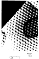
- Figures 1 and 2 are microphotographs, at 5,000x, illustrating this difference for polypropylene fibers stained with RuO4 obtained using the Kozulla process and the process according to the present invention, respectively.
- the skin-core structure of the Kozulla fiber illustrated in Figure 1 is not very distinct, and there is a gradient area between the skin and the core.
- the skin-core structure illustrated in Figure 2 obtained using the process of the present invention, has a clear line of demarcation between the skin and the core, whereby two adjacent discrete portions are provided.
- the physical characteristics of the fibers are also different.
- the average melt flow rate of the fibers obtained according to the present invention is only slightly greater than the melt flow rate of the polymer composition; whereas, in the Kozulla fiber, the average melt flow rate of the fiber is significantly greater than the melt flow rate of the polymer composition. More specifically, for a melt flow rate of the polymer composition of about 10 dg/min, the average melt flow rate of the fiber according to the present invention can be controlled to about 11 to 12 dg/min, which indicates that chain scission degradation has been limited to substantially the skin portion of the skin-core fiber. In contrast, the average melt flow rate for the Kozulla fiber is about 20 to 30 dg/min, which indicates that chain scission degradation has been effected in both the core and the skin of the Kozulla fiber.
- the temperature of the polymer, the temperature of the heated spinnerette or plate, and the quench conditions are controlled to permit, even in a short spin process, the spinning of the filaments with a skin-core structure.
- preferred conditions for each of these variables include the following.
- the polymer to be extruded preferably has a temperature of about 200°C to 325°C, more preferably about 200°C to 300°C, even more preferably 220°C to 260°C, and most preferably about 230°C to 240°C.
- the heated spinnerette preferably has a temperature of at least about 230°C, preferably at least about 250°C, and can be in the range of about 250°C to 370°C, preferably in the range of about 290°C to 360°C, and more preferably in the range of about 330°C to 360°C.
- the apertured plate preferably is heated to a temperature of at least about 250°C, and can be in the range of about 250°C to 370°C, preferably in the range of about 280°C to 350°C, and more preferably in the range of about 300°C to 360°C.
- the oxidative quench gas has a preferred flow rate of about 3,000 to 12,000 ft/min, more preferably a flow rate of about 4,000 to 9,000 ft/min, and even more preferably about 5,000 to 7,000 ft/min. These values can be varied depending on the polymer being treated, and the dimensions of the spin pack assembly including the spinnerette and/or the heated plate.
- the oxidizing environment can comprise air, ozone, oxygen, or other conventional oxidizing environment, at a heated or ambient temperature, at a downstream portion of the spinnerette.
- the temperature and oxidizing conditions at this location must be maintained to ensure that, even in a short spin process, sufficient oxygen diffusion is achieved within the fiber so as to effect oxidative chain scission within at least a surface zone of the fiber to obtain the skin-core filament structure.
- the temperature environment to obtain the skin-core filament structure can be achieved through a variety of heating conditions, and can include the use of heating through conduction, convection, inductance, magnetic heating and radiation.
- heating through conduction, convection, inductance, magnetic heating and radiation.
- resistance or impedance heating, laser heating, magnetic heating or induction heating can be used to heat the spinnerette or a plate associated with the spinnerette.
- the heating substantially uniformly heats the spinnerette or the plate associated with the spinnerette.
- the spinnerette or a plate associated with the spinnerette can comprise a hollow plate having a heat transfer fluid flowing therethrough or can be equipped with a band heater wrapped around its periphery.
- a magnetic field heating device as disclosed in U.S. Patent No.
- FIG. 3 there is schematically illustrated a spinnerette 1 having capillaries 2 through which polymer is extruded to be quenched by the oxidative gas flow Q to form filaments 3.
- a plate 4 Located above the spinnerette is a plate 4 having capillaries 5, which capillaries 5 correspond to capillaries 2 of the spinnerette 1.
- An electric current is provided, such as through leads 6 to the plate 4 to heat the plate either by resistance or impedance.
- the plate 4 can be heated to a suitable temperature, such as a temperature of at least about 250°C to raise the temperature of the polymer as it approaches and passes through the plate 4. More specifically, as the polymer passes through the plate 4, it is heated to a sufficient temperature to permit oxidative chain scission degradation of at least the surface of the molten filament upon extrusion from the spinnerette into the oxidative gas flow Q.
- a suitable temperature such as a temperature of at least about 250°C to raise the temperature of the polymer as it approaches and passes through the plate 4. More specifically, as the polymer passes through the plate 4, it is heated to a sufficient temperature to permit oxidative chain scission degradation of at least the surface of the molten filament upon extrusion from the spinnerette into the oxidative gas flow Q.
- smaller molecular weight molecules are obtainable on the surface of the polymer (as compared to the core) when subjected to oxidative quench conditions due to the differential heating obtained on the surface of the extrudate, as well as due to the additional stress on the polymer stream as the polymer flows to and from the plate 4 to the spinnerette 1.
- the distance "c" between the heated plate 4 and the spinnerette 1 can be varied depending upon the physical and chemical characteristics of the composition, the temperature of the composition and the dimensions of the capillaries 2.
- the capillaries 2 and 5 should have a cross-sectional area "a" of about 0.03 to 0.3 mm2, preferably about 0.1 mm2, and a length "b" of about 1 to 5 mm, preferably about 1.5 mm,
- distance "c" should be about 1 to 4 mm, preferably about 2 to 3 mm, and more preferably about 2.5 mm.
- the capillaries 2 and 5 can be of the same or substantially the same dimensions, as shown in Fig. 3, or can be of different dimensions, such as capillaries 2 being of a smaller or larger diameter than capillaries 5.
- capillaries 5' can have a larger diameter than capillaries 2'.
- capillaries 5' would preferably be up to about 30% wider than capillaries 2', and preferably have a cross-sectional area of about 0.4 mm2.
- a limiting factor on the size of capillaries 5' for embodiments wherein capillaries 5' correspond in number and/or pattern to the capillaries 2' is the ability to maintain the strength of the heated plate while fitting a large number of capillaries therein.
- the spinnerette can be directly heated by various means whereby a heated plate can be omitted.
- an induction coil 7 can be positioned around the spinnerette 8 in order to heat the spinnerette to a sufficient temperature for obtaining the skin-core filament structure.
- the temperature to heat the spinnerette to varies depending upon the chemical and physical characteristics of the polymer, the temperature of the polymer, and the dimensions of the capillaries 9.
- the capillaries 9 would have a cross-sectional area "d" of about 0.02 to 0.2 mm2, preferably about 0.07 mm2, and a length "e" of about 1 to 20 mm, preferably about 1-5 mm, and more preferably about 1.5 mm.
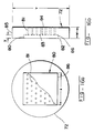
- Fig. 6 shows a modified spinnerette structure wherein the capillaries 10 of spinnerette 11 are countersunk on the upper surface 12 of the spinnerette 11 so that the capillaries 10 include a tapered, upper portion 13.
- Capillaries 10 have a total length of about 3 to 20 mm, preferably about 7-10 mm; a first cross-sectional area 10a of about 0.03 mm2 to 0.2 mm2 at a lower portion; a maximum cross-sectional area 10b at the surface 12 of about 0.07 mm2 to 0.5 mm2, preferably about 0.2 mm2; and the countersunk capillaries taper from the maximum cross-sectional area 10b to the first cross-sectional area 10a at an angle ⁇ of about 20° to 60°, preferably about 35° to 45°, and more preferably about 45°.
- the countersunk capillaries can include a distance "f" between the maximum cross-sectional area 10b to the first cross-sectional area 10a of about 0.15 to 0.4 mm.
- the capillaries can comprise counterbored, countersunk capillaries 49.
- These counterbored, countersunk capillaries can comprise an upper tapered portion 49a having an upper diameter 49b of about 0.6 mm and a length of about 0.5 mm.
- the upper diameter 49b tapers by an angle ⁇ of about 20° to 60°, preferably about 35° to 45°, and more preferably about 45°, to an upper capillary 49c having a diameter of about 0.5 mm and a length of about 3.5 mm.
- a middle tapered portion 49d having a length of about 0.1 mm and an angle ⁇ of about 20° to 60°, preferably about 35° to 45°, and more preferably about 45°, connects the upper capillary 49c to a lower capillary 49e having a diameter of 0.35 mm and a length of about 1.5 mm.
- the capillaries can comprise counterbored capillaries 50.
- These counterbored capillaries 50 can comprise an upper capillary 50a having a diameter of about 0.5 mm and a length of about 4 mm.
- any of the above-described spinnerettes can have a recess at a lower portion, such as recess 50d illustrated in Fig. 8.
- the recess can have a cross-sectional area of about 0.05 to 0.4 mm2, preferably of about 0.3mm2, and a length of about 0.25 mm to 2.5 mm, preferably a length of about 0.5 mm.
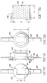
- Fig. 9 illustrates an exemplary illustration of a spin pack assembly according to the present invention for impedance heating of the spinnerette.
- polymer 15 enters the spin pack top 16, passes through filter screen 17, breaker plate 18, and through the heated spinnerette 19 supplied with low voltage through an adjustable clamp 21 from transformer 20.
- the current is preferably about 500 to 3,000 amperes
- the transformer tap voltage is preferably about 1 to 7 volts
- the total power should preferably be about 3 to 21 kilowatts.
- Fig. 10 illustrates an exemplary illustration of a spin pack assembly according to the present invention for induction heating of the spinnerette.
- polymer 29 enters the spin pack top 23, passes through filter screen 24, breaker 25, and through spinnerette 26 heated by induction coil 28 which surrounds the spinnerette.
- Surrounding the spin pack assembly is a Dowtherm manifold 27.
- the oscillating frequency is about 2 to 15 kilohertz, preferably about 5 kilohertz, and the power is about 2-15 kilowatts, preferably 5 kilowatts.
- these values can be varied depending on the polymer being treated, and the dimensions of the spin pack assembly including the dimensions of the spinnerette and/or the heated plate.
- Fig. 11 illustrates a cross-sectional view of a radial quench short spin apparatus 30.
- the radial quench short spin apparatus which is a modified version of apparatus manufactured by Meccaniche Morderne of Milan, Italy, includes a polymer inlet spin pump 31 through which the polymer that is heated to a first temperature, such as at 200°C to 300°C is fed by a plurality of polymer feed ducts 32 to the spin pack assemblies 33 having breaker plates 33a and 33b, and inner and outer retaining rings 33c and 33d and spinnerettes 34.
- the extruded polymer in the form of filaments F are drawn downwardly past the high rate of flow oxidative quench, illustrated by arrows 37, flowing between outer encasement 38 and the cone-shaped conduit 39, and through annular opening 35.
- the annular opening 35 is formed by upper extension 38a of the outer encasement 38, which can be attached by bolts 38b, and metal plate 40.
- a set screw 41 can be tightened to adjustably secure the outer encasement 38 to provide differing lengths.
- thermocouple 42a is positioned in a region near the spin pump 31 to measure the polymer feed temperature
- another thermocouple 42b is positioned near the top of a spinnerette assembly 33 to measure the polymer temperature at the spinnerette head.
- Bolts 44 are employed for releasably securing each of the spin pack assemblies 33 in place.
- a band heater 45 can surround the spin pack assemblies 33 for maintaining or adjusting the melt temperature of the polymer melt.
- copper terminals 36 are attached to the spinnerette for connection to an electrical source (not shown). Also, insulation is provided at 46, 47 and 48.
- the quench flow can be effected by other than the radial flow illustrated in Fig. 11, and various other manners of providing a high rate of oxidative quench gas to the filaments as they exit the spinnerette can be used.
- a nozzle can be positioned relative to each spinnerette so as to direct a high flow rate of oxidative quench gas to the filaments as they exit each spinnerette.
- One such nozzle, as illustrated in Fig. 12, is available from Automatik of Germany.
- This nozzle 51 is movably mounted using elements 52 to most preferably be directed towards the center of the spinnerette 53 at an angle ⁇ with respect to a plane longitudinal passing through the spinnerette of about 0° to 60°, more preferably about 10° to 60°, and can also preferably be an angle of about 0° to 45°, more preferably 0° to 25°.
- the various elements of the spin pack assembly of the present invention can be constructed using conventional materials of construction, such as stainless steel, including 17-4PH stainless steel, 304 stainless steel and 416 stainless steel, and nickelchrome, such as nickelchrome-800H.
- stainless steel including 17-4PH stainless steel, 304 stainless steel and 416 stainless steel
- nickelchrome such as nickelchrome-800H.
- the spun fiber obtained in accordance with the present invention can be continuous and/or staple fiber of a monocomponent or bicomponent type, and preferably falls within a denier per filament (dpf) range of about 0.5-30, more preferably is no greater than about 5, and preferably is between about 0.5 and 3.0.
- dpf denier per filament
- At least one melt stabilizer and/or antioxidant is mixed with the extrudable composition.
- the melt stabilizer and/or antioxidant is preferably mixed in a total amount with the polypropylene to be made into a fiber in an amount ranging from about 0.005-2.0 weight % of the extrudable composition, preferably about 0.03-1.0 weight %.
- Such stabilizers are well known in polypropylene-fiber manufacture and include phenylphosphites, such as IRGAFOS 168 (available from Ciba Geigy Corp.), ULTRANOX 626 (available from General Electric Co.), and SANDOSTAB PEP-Q (available from Sandoz Chemical Co.); and hindered phenolics, such as IRGANOX 1076 (available from Ciba Geigy Corp.) and CYANOX 1790 (available from American Cyanamid Co.); and N,N'-bis-piperidinyl diamine-containing materials, such as CHIMASSORB 119 and CHIMASSORB 944 (available from Ciba Geigy Corp.).
- phenylphosphites such as IRGAFOS 168 (available from Ciba Geigy Corp.), ULTRANOX 626 (available from General Electric Co.), and SANDOSTAB PEP-Q (available from Sandoz Chemical Co.); and hindered phenolics, such as
- the at least one melt stabilizer and/or antioxidant can be mixed into the extrudable composition, or can be separately added to polypropylenes that are to be mixed together to form the extrudable composition.
- whiteners such as titanium dioxide
- antiacids such as calcium stearate
- colorants in amounts ranging from 0.01-2.0 weight%
- additives can included in the fiber of the present invention.
- Wetting agents such as disclosed in U.S. Pat. No. 4,578,414, incorporated herein by reference, are also usefully incorporated into the fiber of the present invention.
- Other commercially available useful additives include LUPERSOL 101 (available from Pennwalt Corp.)
- metal carboxylates can be added to the polymer material. These metal carboxylates are known for use in polymer materials to be subjected to thermal bonding, and a small amount of metal carboxylates is believed to lower the surface fusion temperature of polymer materials, such as polypropylene fiber.
- Typical metal carboxylates include nickel salts of 2-ethylhexanoic, caprylic, decanoic and dodecanoic acids, and 2-ethylhexanoates of Fe, Co, Ca and Ba.
- Preferred metal carboxylates include nickel octoates, such as a 10% solution in mineral spirits of nickel octoate obtained from Shepherd Chemical Co., Cincinnati, Ohio.
- the metal carboxylates are included in the polymer material to be made into fibers or filaments in a concentration of about 7 ppm to 1000 ppm, most preferably about 700 ppm.
- Fibers were produced using both small-scale developmental tests and pilot plant tests, under the operating conditions tabulated in Table I. More specifically, the different polymers, their temperatures and spin conditions, and differing conditions are tabulated in Table I, accompanied by information pertaining to the skin-core structure of the resulting fibers based on microfusion analysis.
- test procedures tabulated in the examples in Table I include the following:
- Examples 1-67 utilized a heated apertured plate in a small-scale developmental test, with Examples 22-44 incorporating 0.00019% Ultranox 626 as an antioxidant stabilizer.
- Examples 68-75 and 188-196 utilized a heated spinnerette having recessed capillaries in a small-scale developmental test.
- Examples 76-79 utilized a heated apertured plate in a small-scale developmental test wherein heating was achieved with a band heater.
- Examples 80-89 utilized a heated spinnerette in a small-scale developmental test wherein heating was achieved with a band heater.
- Examples 90-187 utilized a heated spinnerette having recessed capillaries in a pilot plant test, with Examples 90-150 using an extruder temperature of 240 to 280°C, and Examples 151-187 using an extruder temperature of 285 to 300°C.
- Examples 197-202 utilized a heated spinnerette without recessed capillaries in a small-scale developmental test.
- Examples 203-313 utilized a heated spinnerette without recessed capillaries in a pilot plant test.
- Examples 314-319 utilized a heated spinnerette without recessed capillaries in a small-scale developmental test, wherein the polypropylene contained nickel octoate.
- Examples 320-324 utilized a heated spinnerette without recessed capillaries in a small-scale developmental test, wherein the polymer was polyethylene.
- Examples 325-331 utilized a spinnerette without recessed capillaries in a small-scale developmental test, wherein the polymer was polyester.
- a directly heated spinnerette 60 was constructed from nickel chrome - 800H having dimensions, as illustrated in Fig. 13a, of 0.3 inch (dimension "g") x 0.25 inch (dimension “h") including 59 capillaries 61 positioned in alternating rows of 6 and 7 capillaries having a diameter of 0.012 inch (0.3 mm) and length of 0.12 inch, with the spinnerette having a corresponding thickness of 0.12 inch.
- the spinnerette 60 is inserted into a recess 64 of spinnerette holder 63, which recess 64 has corresponding dimensions of 0.3 inch (dimension “g'") by 0.25 inch (dimension “h'”) to the spinnerette 60, and a depth of 0.1 inch (dimension “o”).
- the spinnerette holder has an upper portion 65 having a diameter of 0.745 inch (dimension "n"), and a thickness of 0.06 inch (dimension "l”), and a lower portion 66 having a diameter 0.625 inch (dimension "m”) and a thickness to provide an overall thickness of 0.218 inch (dimension "k”) for the spinnerette holder 63.
- copper terminals 68 were connected to the upper surface 67 of the spinnerette holder 63 for connection to a power source (not shown).
- this spinnerette was mounted in a spin pack assembly 69.
- the spin pack assembly 69 included, in sequential order, a polymer feed distributor 70, a filter 71, a distributor 72, a spacer 73, the spinnerette 60, and a lower clamping element 74.
- the spin pack assembly was attached to a polymer pipe 108 for directing polymer through inlet 109 to the spin pack assembly 69. Further, a band heater 110 and insulation 111 surrounded the assembly.
- the polymer feed distributor 70 which was constructed from 17-4PH stainless steel, included a lower portion 75 having a diameter of 0.743 inch (dimension "p") and a thickness of 0.6 inch (dimension "q"), and an upper portion 76 having a diameter of 0.646 inch (dimension "r”) and a thickness to provide an overall thickness to the polymer feed distributor 70 of 0.18 inch (dimension "s").
- Centrally located in the polymer feed distributor 70 was a conically-spaced opening 77 having, on surface 78, a lower diameter of 0.625 inch (dimension "t”) tapering inwardly and upwardly to upper surface 79 at an angle "u" of 72°.
- the filter screen 71 included a combination of three 304 stainless steel screens surrounded by a 24 gauge (0.02 inch thick) aluminum binder.
- the filter screens included a first screen of 250 mesh, a second screen of 60 mesh and a third screen of 20 mesh.
- the aluminum binder had an inner diameter (forming an opening for the filter screen) of 0.63 inch, an outer diameter of 0.73 inch, and a thickness of 0.094 inch.
- the distributor 72 which was constructed from 17-4PH stainless steel, included an element 85 of round cross-section having a diameter of 0.743 inch (dimension "v") and a thickness of 0.14 inch (dimension “w”).
- a square-shaped recess 83 was centrally located in the upper surface 82 of the element 85 having edges 86 of 0.45 inch (dimension "x") and a depth to a lower recess surface 83 of 0.02 inch (dimension "y”).
- the element further included 46 capillaries enabling flow of polymer from the lower recess surface 83 through the lower surface 84 of element 85.
- the capillaries had a diameter of 3/64 inch, were uniformly spaced, and included 4 rows of seven capillaries alternating with 3 rows of 6 capillaries.
- the capillaries were spaced from edges 86 of the recess 80 by approximately 0.06 inch.
- the spacer 73 which was constructed from 416 stainless steel, included an upper element 87 having an outer diameter of 0.743 inch (dimension “z") and a thickness of 0.11 inch (dimension “aa”) and a lower element 88 having an outer diameter of 0.45 inch (dimension “bb”) and a thickness of 0.07 inch (dimension “cc”) to provide an overall thickness of 0.18 inch (dimension “dd”). Further, the spacer 73 included an opening 89 having a maximum diameter at the surface 91 of the upper element 87 and tapered inwardly and downwardly along the conically-shaped taper 90 to point 92 where the lower element 88 begins, and then maintained a constant diameter of 0.375 inch (dimension "ff”) to lower surface 93.
- lower clamping element 74 which was constructed from 416 stainless steel, included an element 94 having an outer diameter of 2 inches (dimension “gg") and a thickness of 0.4 inch (dimension “kk”).
- An opening 95 communicated upper surface 96 of element 94 to lower surface 97.
- Opening 95 included a maximum diameter of 0.75 inch (dimension “hh") at the upper surface 96, and maintained this maximum diameter for 0.34 inch (dimension “ii”) where the diameter was reduced to 0.64 inch (dimension "jj”) and maintained this reduced diameter until lower surface 97, whereby a recessed surface 98 was obtained against which the spinnerette holder 63 was pressed when bolts (not shown) positioned in openings 99 were tightened.
- Openings 99 have been omitted from Fig. 18b.
- Slot 100 having a width of 0.25 inch (dimension “ll") was located in the element 94 to a depth of 0.28 inch (dimension "mm") for receiving and permitting the copper terminals 68 to protrude from the spin pack assembly 69.
- the structure of the spin pack assembly was similar to that of the above-described heated spinnerette assembly; however, the heated plate was added to the assembly and the spinnerette had a different number of capillaries.
- the small-scale developmental test assembly 101 included a spin pack assembly 102 having a polymer feed distributor 103, a filter screen 104, a distributor 105, a heated plate 106,a spinnerette 60, copper terminal 68 and a lower clamping element 107.
- the spin pack assembly 102 was attached to a polymer pipe 108 for directing polymer through inlet 109 to the spin pack assembly 102. Further, a band heater 110 and insulation 111 surrounded the assembly.
- the heated plate 112 which was constructed of stainless steel, is similar in construction to the distributor 72 as illustrated in Figs. 16a and 16b. However, in contrast to the distributor, the heated plate 112 included copper terminals 113 for connection to a source of electricity (not shown), and included 186 capillaries 115 situated below a 0.1 inch deep recess 116 for flow of polymer in the direction indicated by arrow 114.
- the capillary layout is illustrated in Fig. 20a, wherein there are partially shown 186 capillaries 115 positioned in alternating rows of 15 and 16 capillaries having a diameter of 0.012 inch and a length of 0.078 inch (2 mm).
- the capillaries had a diameter of 0.3 mm and a total length of 4.0 mm, and the recessed portions had a diameter of 0.5 mm and a length of 1.0 mm.
- the spinnerette included 30,500 capillaries having a diameter of 0.3 mm and a length of 1.5 mm.
- a 20 Kilowatt transformer having a maximum voltage of 7.5 volts, and a nominal voltage of 2 to 3 volts, with the secondary current being 34 times the primary current, was used for heating the spinnerette.
- the band heater was a CHROMALOX mica insulated band heater of 150 watts and 120 volts.
- Polymer A denotes linear isotactic polypropylene pellets having a melt flow rate of 18 ⁇ 2 dg/min obtained from Himont, Inc.
- Polymer B denotes linear isotactic polypropylene pellets having a melt flow rate of 9.5 ⁇ 2 dg/min obtained from Himont, Inc.
- Stabilizer denotes the antioxidant stabilizer Ultranox 626 obtained from the General Electric Co.
- PE denotes DOW 6811A polyethylene
- polyester was Barnette Southern recycled bottle chips.
Abstract
Description
- The present invention relates to synthetic fibers, especially synthetic fibers used in the manufacture of nonwoven fabrics. In particular, the present invention relates to processes and apparatus for the production of polymer fibers and filaments. More specifically, the present invention relates to skin-core fibers produced using melt spin processes, including short spin and long spin processes, and to articles incorporating these skin-core fibers.
- The production of polymer fibers and filaments usually involves the use of a mix of a single polymer with nominal amounts of stabilizers and pigments. The mix is melt extruded into fibers and fibrous products using conventional commercial processes. Non-woven fabrics are typically made by making a web of the fibers, and then thermally bonding the fibers together where they meet. More specifically, staple fibers are converted into non-woven fabrics using, for example, a carding machine, and the carded fabric is thermally bonded. The thermal bonding can be achieved using various heating techniques, including heating with heated rollers and heating through the use of ultrasonic welding.
- Conventional thermally bonded non-woven fabrics exhibit good loft and softness properties, but less than optimal cross-directional strength, and less than optimal cross-directional strength in combination with high elongation. The strength of the thermally bonded non-woven fabrics depends upon the orientation of the fibers and the inherent strength of the bond points.
- Over the years, improvements have been made in fibers which provide stronger bond strengths. However, further improvements are needed to provide even higher fabric strengths to permit use of these fabrics in today's high speed converting processes for hygiene products, such as diapers and other types of incontinence products. In particular, there is a need for a thermally bondable fiber and a resulting nonwoven fabric that possess high cross-directional strength and high elongation.
- Further, there is a need to produce thermally bondable fibers that can achieve superior cross-directional strength, elongation and toughness properties in combination with fabric uniformity and loftiness. In particular, there is a need to obtain fibers that can produce carded, calendared fabrics with cross-directional properties on the order of at least 650 g/in, with an elongation of 140-180%, and a toughness of 480-700 g/in for a 20 g/yd² fabric bonded at speeds as high as 500 ft/min or more.
- A number of patent applications have been filed by the present assignee which are directed to improvements in polymer degradation, spin and quench steps, and extrusion compositions that enable the production of fibers having an improved ability to thermally bond accompanied by the ability to produce non-woven fabric having increased strength, elongation, toughness and integrity. For example, Kozulla U.S. Patent No. 5,281,378, issued January 25, 1994, and Kozulla U.S. Patent Application Nos. 07/474,897, filed February 5, 1990, 07/683,635, filed April 11, 1991, 07/836,438, filed February 18, 1992, and 07/939,857, filed September 2, 1992 are directed to processes for preparing polypropylene containing fibers by extruding polypropylene containing material having a molecular weight distribution of at least about 5.5 to form hot extrudate having a surface, with quenching of the hot extrudate in an oxygen containing atmosphere being controlled so as to effect oxidative chain scission degradation of the surface. For example, the quenching of the hot extrudate in an oxygen containing atmosphere can be controlled so as to maintain the temperature of the hot extrudate above about 250°C for a period of time to obtain oxidative chain scission degradation of the surface.
- By controlling the quenching to obtain oxidative chain scission degradation of the surface, the resulting fiber essentially contains a plurality of zones, defined by different characteristics including differences in melt flow rate, molecular weight, melting point, birefringence, orientation and crystallinity. In particular, as disclosed in these applications, the fiber produced by the delayed quench process includes an inner zone identified by a substantial lack of oxidative polymeric degradation, an outer zone of a high concentration of oxidative chain scission degraded polymeric material, and an intermediate zone identified by an inside-to-outside increase in the amount of oxidative chain scission polymeric degradation. In other words, the quenching of the hot extrudate in an oxygen containing atmosphere can be controlled so as to obtain a fiber having a decreasing weight average molecular weight towards the surface of the fiber, and an increasing melt flow rate towards the surface of the fiber. For example, the fiber comprises an inner zone having a weight average molecular weight of about 100,000 to 450,000 grams/mole, an outer zone, including the surface of the fiber, having a weight average molecular weight of less than about 10,000 grams/mole, and an intermediate zone positioned between the inner zone and the outer zone having a weight average molecular weight and melt flow rate intermediate the inner zone and the outer zone. Moreover, the inner, core zone has a melting point and orientation that is higher than the outer surface zone.
- Further, U.S. Application Serial Nos. 08/003,696, filed January 13, 1993, 07/943,190, filed September 11, 1992, and 07/818,772, filed January 13, 1992, to Gupta et al. are directed to processes for spinning polypropylene fibers, and the resulting fibers and products made from such fibers. The processes of the Gupta et al. applications include melt spinning a polypropylene composition having a broad molecular weight distribution through a spinnerette to form molten fibers, and quenching the molten fibers to obtain thermally bondable polypropylene fibers. The processes of the Gupta et al. applications can be used in both a two step "long spin" process, as well as in a one step "short spin" process. According to certain aspects of the invention disclosed in the Gupta et al. applications substantially constant characteristics are maintained within the material forming the fiber, such as rheological polydispersity index and melt flow rate, as the material is extruded, quenched and drawn, and a substantially uniform fiber is obtained.
- More specifically, with regard to known processes for making staple fiber, these processes include the older two-step "long spin" process and the newer one-step "short spin" process. The long spin process involves first melt-extruding fibers at typical spinning speeds of 500 to 3000 meters per minute, and more usually depending on the polymer to be spun from 500 to 1500 meters per minute. Additionally, in a second step usually run at 100 to 250 meters per minute, these fibers are drawn, crimped, and cut into staple fiber. The one-step short spin process involves conversion from polymer to staple fibers in a single step where typical spinning speeds are in the range of 50 to 200 meters per minute. The productivity of the one-step process is increased with the use of about 5 to 20 times the number of capillaries in the spinnerette compared to that typically used in the long spin process. For example, spinnerettes for a typical commercial "long spin" process would include approximately 50-4,000, preferably approximately 3,000-3,500 capillaries, and spinnerettes for a typical commercial "short spin" process would include approximately 500 to 100,000 capillaries preferably, about 30,000-70,000 capillaries. Typical temperatures for extrusion of the spin melt in these processes are about 250-325°C. Moreover, for processes wherein bicomponent filaments are being produced, the numbers of capillaries refers to the number of filaments being extruded, and usually not the number of capillaries in the spinnerette.
- The short spin process for manufacture of polypropylene fiber is significantly different from the conventional long spin process in terms of the quenching conditions needed for spin continuity. In the short spin process, with high hole density spinnerettes spinning around 100 meters/minute, quench air velocity is required in the range of about 3,000-8,000 ft/minute to complete fiber quenching within one inch below the spinnerette face. To the contrary, in the long spin process, with spinning speeds of about 1000-1500 meters/minute, a lower quench air velocity in the range of 300 to 500 ft./minute is used. Therefore, achieving a skin-core type fiber, such as that disclosed in the above-identified Kozulla applications (which controls quenching to achieve a delayed quenching) is difficult in a short spin process due to the high quench air velocity needed for the short spin process.
- Apparatus and methods are also known for melt spinning of polymers to obtain certain advantages in the spinning process. For example, U.S. Patent No. 3,354,250 to Killoran et al. (Killoran), which is hereby incorporated by reference in its entirety, is directed to extrusion method and apparatus wherein contact of molten or plastic material with moving parts is avoided and the residence time of the polymer in the molten condition is kept to a minimum. Specifically, in the extrusion system of Killoran, the splined barrel is cooled, rather than heated, by a surrounding water-cooling jacket which carries away heat, so as to maintain the screw, barrel and powder at a temperature below the melting point of the lowest melting additive.
- In describing the processing of polypropylene, Killoran teaches that the softening temperature of polypropylene is within the range from 168°C to 170°C, and at this temperature the material becomes semi-plastic and sticky. Killoran further teaches that the temperature required for filtering and extrusion of polypropylene may be as high as 280°C, so that the temperature of the polypropylene is increased during the passage through perforations in the block from approximately 170°C to 270°C, or 280°C, that is, there is about 100°C rise from the initial softening at the entrance to the block to the molten condition at the outlet of the block. Therefore, the teachings of Killoran are limited to heating of the polymer from a solid condition to a molten condition to achieve a reduced amount of time that the polymer is in a molten condition, as well as to the prevent polymer in the molten condition from contacting moving elements.
- Further, U.S. Patent No. 3,437,725 to Pierce, which is hereby incorporated by reference in its entirety, is directed to the melt-spinning of synthetic polymers, including polypropylene. According to the invention of Pierce, the spinnerette is designed so as to enable the use of polymers having higher melt viscosities, either from high molecular weight polymers or from polymers with stiff chain structures. Specifically, the spinnerette of Pierce is designed so as to permit the spinning of polymer having a high melt viscosity without degrading the polymer. To accomplish this lack of degradation of the polymer, Pierce passes the molten polymer through the filter holder at an initial temperature within a temperature range below that at which significant polymer degradation will occur, passes the polymer into a plurality of passages, each of which leads to a different spinning capillary in the spinnerette plate and has an entrance temperature within the initial temperature range, heats the spinnerette plate to increase the temperature along the passages from the temperature at the entrance to a temperature at least 60°C higher at the spinning capillary, and extrudes the polymer from the spinning capillary after a maximum of 4 seconds of travel through the heated passage. The quenching of Pierce is performed using inert gas and the process is accomplished using a long spin, two step process wherein the filaments are initially spun, and subsequently drawn.
- It is an object of the present invention to obtain skin-core filaments or fibers using melt spin processes. It is also an object of the present invention to enable control of the skin-core structure of the fibers or filaments, whereby a skin-core structure can be obtained which possesses either a gradient or a distinct step between the core and the surface of the fiber.
- The objects of the present invention can be obtained by providing a process for spinning polymer filaments, comprising feeding a polymer composition to at least one spinnerette; heating the polymer composition at a location at or adjacent to the at least one spinnerette so as to heat the polymer composition to a sufficient temperature to obtain a skin-core filament structure upon quenching in an oxidative atmosphere; extruding the heated polymer composition through the at least one spinnerette to form molten filaments; and immediately quenching the molten filaments in an oxidative atmosphere, as the molten filaments are extruded, to effect oxidative chain scission degradation of at least a surface of the molten filaments to obtain filaments having a skin-core structure.
- The objects of the present invention are also achieved by providing a process for spinning polymer filaments, comprising feeding a polymer composition to at least one spinnerette; heating the polymer composition at a location at or adjacent to the at least one spinnerette so as to obtain sufficient heating of the polymer composition to partially degrade the polymer composition in a vicinity of the at least one spinnerette; extruding the partially degraded polymer composition through the at least one spinnerette to form molten filaments; and immediately quenching the molten filaments in an oxidative atmcsphere, as the molten filaments are extruded, to effect oxidative chain scission degradation of at least a surface of the molten filaments to obtain filaments having a skin-core structure.
- In another embodiment of the invention, the objects of the present invention are obtained by providing a process for spinning polymer filaments, comprising feeding a polymer composition to at least one spinnerette; heating the at least one spinnerette to a temperature of at least about 230°C; extruding the heated polymer composition through the at least one spinnerette to form molten filaments; and immediately quenching the molten filaments in an oxidative atmosphere, as the molten filaments are extruded, to effect oxidative chain scission degradation of at least a surface of the molten filaments to obtain filaments having a skin-core structure.
- In still another embodiment of the invention, the objects of the present invention are obtained by providing a process for spinning polymer filaments, comprising feeding a polymer composition to at least one spinnerette; heating at least one apertured element positioned upstream of the at least one spinnerette to a temperature of at least about 250°C; extruding the heated polymer composition through the at least one apertured element and the at least one spinnerette to form molten filaments; and immediately quenching the molten filaments in an oxidative atmosphere, as the molten filaments are extruded, to effect oxidative chain scission degradation of at least a surface of the molten filaments to obtain filaments having a skin-core structure.
- The objects of the present invention are also obtainable by providing apparatus for spinning polymer filaments, and, in particular, apparatus for performing the processes of the present invention.
- Therefore, according to one embodiment of the present invention, apparatus is provided for spinning polymer filaments, comprising at least one spinnerette; means for feeding a polymer composition through the at least one spinnerette to extrude molten filaments; means for heating the polymer composition at a location at or adjacent to the at least one spinnerette to obtain sufficient heating of the polymer composition to obtain a skin-core filament structure upon quenching in an oxidative atmosphere; and means for immediately quenching molten filaments of extruded polymer in an oxidative atmosphere, as the molten filaments exit the at least one spinnerette, to effect oxidative chain scission degradation of at least a surface of the molten filaments to obtain filaments having a skin-core structure.
- In another embodiment of the apparatus of the present invention, the apparatus for spinning polymer filaments comprises at least one spinnerette; means for feeding a polymer composition through the at least one spinnerette to extrude molten filaments; means for substantially uniformly heating the polymer composition at a location at or adjacent to the at least one spinnerette so as to obtain sufficient heating of the polymer composition to partially degrade the polymer composition in a vicinity of the at least one spinnerette; and means for immediately quenching molten filaments of extruded polymer in an oxidative atmosphere, as the molten filaments exit the at least one spinnerette, so as to effect oxidative chain scission degradation of at least a surface of the molten filaments.
- In still another embodiment of the apparatus of the present invention, the apparatus for spinning polymer filaments comprises at least one spinnerette; means for feeding a polymer composition through the at least one spinnerette to extrude molten filaments; means for substantially uniformly heating the at least one spinnerette to a temperature of at least about 230°C; and means for quenching molten filaments of extruded polymer in an oxidative atmosphere, as the molten filaments exit the at least one spinnerette, to effect oxidative chain scission degradation of at least a surface of the molten filaments to obtain filaments having a skin-core structure.
- In still another embodiment of the apparatus of the present invention, the apparatus for spinning polymer filaments comprises at least one spinnerette; means for feeding a polymer composition through the at least one spinnerette to extrude molten filaments; at least one apertured element positioned upstream of the at least one spinnerette; means for substantially uniformly heating the at least one apertured element to a temperature of at least about 250°C; and means for quenching molten filaments of extruded polymer in an oxidative atmosphere, as the molten filaments exit the at least one spinnerette, to effect oxidative chain scission degradation of at least a surface of the molten filaments to obtain filaments having a skin-core structure.
- The present invention is also directed to a fiber or filament comprising an inner core of polymeric material; a surface zone surrounding the inner core, the surface zone comprising oxidative chain scission degraded polymeric material, so that the inner core and the surface zone comprise a skin-core structure; and the oxidative chain scission degraded polymeric material being substantially limited to the surface zone wherein the inner core and the surface zone comprise adjacent discrete portions of the skin-core structure.
- In a still further aspect of the invention, the fiber or filament comprises an inner core of polymeric material; a surface zone having a thickness of at least about 0.5 µm, and more preferably at least about 1 µm, surrounding the inner core, the surface zone comprising oxidative chain scission degraded polymeric material, so that the inner core and the surface zone comprise a skin-core structure; and the oxidative chain scission degraded polymeric material being substantially limited to the surface zone so that the inner core and the surface zone comprise adjacent discrete portions of the skin-core structure.
- The invention is also directed to a fiber or filament comprising an inner core of polymeric material; a surface zone surrounding the inner core, the surface zone comprising oxidative chain scission degraded polymeric material, so that the inner core and the surface zone comprise a skin-core structure; and the inner core has a melt flow rate substantially equal to an average melt flow rate of the inner core and the surface zone.
- It is also an object of the present invention to provide non-woven materials comprising fibers according to the invention thermally bonded together, as well as to provide hygienic products comprising at least one absorbent layer, and at least one non-woven fabric comprising fibers of the present invention thermally bonded together. The hygienic article can comprise a diaper having an outer impermeable layer, an inner non-woven fabric layer, and an intermediate layer. Such hygienic products are disclosed in the above-referenced Kozulla and Gupta et al. applications, which have been incorporated by reference in their entirety herein.
- The polymeric material in each of the above fibers or filaments can comprise various polymeric materials, such as polyolefins, polyesters, polyamides, polyvinyl acetates, polyvinyl alcohol and ethylene acrylic acid copolymers. For example, polyolefins can comprise polyethylenes, such as low density polyethylenes, high density polyethylenes, and linear low density polyethylenes, including polyethylenes prepared by copolymerizing ethylene with at least one C₃-C₁₂ alpha-olefin; polypropylenes, such as atactic, syndiotactic, and isotactic polypropylene - including partially and fully isotactic, or at least substantially fully isotactic - polypropylenes; polybutenes; such as poly-1-butenes, poly-2-butenes, and polyisobutylenes, and poly 4-methyl-1-pentenes; polyesters can comprise poly(oxyethyleneoxyterephthaloyl); and polyamides can comprise poly(imino-1-oxohexamethylene) (Nylon 6), hexamethylene-diaminesebacic acid (Nylon 6-10), and polyiminohexamethyleneiminoadipoyl (Nylon 66). Preferably, the polymeric material comprises polypropylene, and, preferably, the inner core of the fiber or filament has a melt flow rate of about 10, and the average melt flow rate of the fiber or filament is about 11 or about 12.
- In the process and apparatus of the present invention, the heating of the polymer composition at a location at or adjacent to the at least one spinnerette comprises heating the polymer composition to a temperature of at least about 200°C, preferably at least about 220°C, and more preferably at least about 250°C. Moreover, the extruding of the heated polymer composition comprises extruding at a temperature of at least about 200°C, preferably at least about 220°C, and more preferably at least about 250°C.
- In the process and apparatus of the present invention, the spinnerette can be directly heated and/or an element associated with the spinnerette, such as an apertured plate, can be heated. Preferably, the spinnerette or the associated element is substantially uniformly heated to ensure that substantially all, and preferably all, filaments extruded through the spinnerette are capable of achieving sufficient conditions to obtain a skin-core structure.
- The heating of the spinnerette can be to a temperature of at least about 230°C, preferably at least about 250°C, and can be in the range of about 250°C to 370°C, preferably in the range of about 290°C to 360°C, and more preferably in the range of about 330°C to 360°C.
- The spinnerette according to the present invention preferably contains about 500 to 150,000 capillaries, with preferred ranges being about 30,000 to 120,000 capillaries, about 30,000 to 70,000 capillaries, and about 30,000 to 45,000 capillaries. These capillaries can have a cross-sectional area of about 0.02 to 0.2 mm², preferably about 0.07 mm², and a length of about 1 to 20 mm, preferably a length of about 1 to 5 mm, and more preferably a length of about 1.5 mm. The capillaries can have a recess at a lower portion, and the recess can have a cross-sectional area of about 0.05 to 0.4 mm², preferably of about 0.3 mm², and a length of about 0.25 mm to 2.5 mm, preferably a length of about 0.5 mm.
- Additionally, the capillaries can have a tapered upper portion. These tapered capillaries can comprise countersunk capillaries having a total length of about 3 to 20 mm, preferably about 7-10 mm; a first cross-sectional area of about 0.03 mm² to 0.2 mm² at a lower portion; a maximum cross-sectional area at a surface of the at least one spinnerette of about 0.07 mm² to 0.5 mm², preferably about 0.2 mm²; and the countersunk capillaries taper from the maximum cross-sectional area to the first cross-sectional area at an angle of about 20° to 60°, preferably about 35° to 45°, and more preferably about 45°. The countersunk capillaries can include a distance between the maximum cross-sectional area to the first cross-sectional area of about 0.15 to 0.4 mm.
- The tapered capillaries can comprise counterbored, countersunk capillaries. These counterbored, countersunk capillaries can comprise an upper tapered portion having a diameter of about 0.6 mm and a length of about 0.5 mm; an upper capillary having a diameter of about 0.5 mm and a length of about 3.5 mm; a middle tapered portion having a length of about 0.1 mm; and a lower capillary having a diameter of about 0.35 mm and a length of about 1.5 mm.
- Further, the tapered capillaries can comprise counterbored capillaries. These counterbored capillaries can comprise an upper capillary having a diameter of about 0.5 mm and a length of about 4 mm; a middle tapered portion having a length of about 0.1 mm; and a lower capillary having a diameter of about 0.35 mm and a length of about 2 mm.
- When the heating comprises heating with an apertured element, preferably an apertured plate, the apertured plate is positioned upstream of the spinnerette, preferably about 1 to 4 mm, preferably about 2 to 3 mm, and more preferably about 2.5 mm. The spinnerette and the apertured plate can comprise a corresponding number of capillaries and have a corresponding pattern, or there can be a different number of capillaries and/or a different pattern. The capillaries in the apertured plate can have a cross-sectional area that is up to about 30% larger than the cross-sectional area of capillaries in the spinnerette.
- The apertured plate preferably contains about 500 to 150,000 capillaries, with preferred ranges being about 30,000 to 120,000 capillaries, about 30,000 to 70,000 capillaries, and about 30,000 to 45,000 capillaries. These capillaries preferably having a cross-sectional area of about 0.03 mm² to 0.3 mm², more preferably of about 0.1 mm², and a length of about 1 to 5 mm, more preferably about 1.5 mm.
- The heating of the apertured plate can be to a temperature of at least about 250°C, and can be in the range of about 250°C to 370°C, preferably in the range of about 280°C to 350°C, and more preferably in the range of about 300°C to 360°C.
- The quenching can comprise any quench with an oxidative gas that flows at a high rate of speed, preferably about 3,000 to 12,000 ft/min, more preferably about 4,000 to 9,000 ft/min, and even more preferably 5,000 to 7,000 ft/min. Preferably, the molten filaments are immediately quenched upon being extruded. Examples of quenching according to the present invention include radial quenching and quenching with adjustable nozzles blowing an oxidative gas. The adjustable nozzles are preferably directed at a central portion of the spinnerette, and preferably have an angle of about 0° to 60° with respect to a plane passing through the surface of the spinnerette, more preferably about 10° to 60°, and can also preferably be an angle of about 0° to 45°, more preferably 0° to 25°.
- The heating can be accomplished using conduction, convection, induction, magnetic heating and/or radiation, and can be accomplished using impedance or resistance heating, inductance heating and/or magnetic heating.
- The polymer composition can comprise various spinnable polymers, including polyolefins, such as polyethylene and polypropylene, and polyesters. The polymer can have usual spinning temperatures temperature, i.e., the polymer melt temperature, and a narrow or broad molecular weight distribution. For polypropylene, the temperature of the melt spin composition is about 200°C to 300°C, preferably 220°C to 260°C, and more preferably 230°C to 240°C,the melt flow rate is preferably about 0.5 to 40 dg/min, with preferred ranges being 5-25 dg/min, 10-20 dg/min, 9-20 dg/min and 9-15 dg/min. Preferably, the polypropylene composition has a broad molecular weight distribution of at least about 4.5. Moreover, polymer compositions as disclosed in either the Kozulla or Gupta et al. applications referred to above can be utilized in the present invention, which polymer compositions are expressly incorporated by reference herein. For example, the molecular weight distribution of the polymer composition can be at least about 5.5, as disclosed by Kozulla.
- At least one metal carboxylate can be added to the polymer composition. The metal carboxylate can comprise at least one member selected from the group consisting of nickel salts of 2-ethylhexanoic, caprylic, decanoic and dodecanoic acids, and 2-ethylhexanoates of Fe, Co, Ca and Ba, such as nickel octoate.
- Preferably, in each of the embodiments of the invention the polymer composition can be fed to the at least one spinnerette at a flow rate of about 10 to 200 meters per minute, and more preferably at a flow rate of about 80 to 100 meters per minute. Moreover, preferably, the extruded heated and/or partially degraded polymer composition can have a flow rate of about 10 to 200 meters per minute, and more preferably a flow rate of about 80 to 100 meters per minute. In other words, the preferred spinning speed is about 10 to 200 meters per minute, and more preferably about 80 to 100 meters per minute.
- Additionally, the process and apparatus of the present invention are also preferably arranged so as to effect oxidative chain scission degradation of at least a surface of the molten filaments to obtain filaments having a skin-core structure capable of forming non-woven materials having a cross directional strength of at least 650 g/in for a 20 g/yd² fabric bonded at speeds of at least 250 ft/min.
- The spinnerette can have various dimensions, with preferred dimensions being a width of about 30-150 mm and a length of about 300 to 700 mm, such as a width of about 40 mm and a length of about 450 mm, or a width of about 100 mm and a length of about 510 mm. The spinnerette can be circular having a preferred diameter of about 100 to 600 mm, more preferably about 400 mm, especially when using a radial quench.
- The invention will be better understood and characteristics thereof are illustrated in the annexed drawings showing non-limiting embodiments of the invention, in which:
- Fig. 1 illustrates a microphotograph of a polypropylene fiber stained with RuO₄ obtained using the Kozulla process.
- Fig. 2 illustrates a microphotograph of a polypropylene fiber stained with RuO₄ obtained using the process of the present invention.
- Fig. 3 illustrates an electrically heated plate associated with a spinnerette for providing the skin-core filamentary structure according to the present invention;
- Fig. 4 illustrates another embodiment of an electrically heated plate associated with a spinnerette for providing the skin-core filamentary structure according to the present invention;
- Fig. 5 illustrates a spinnerette for providing the skin-core filamentary structure according to the present invention which is heated by induction heating;
- Fig. 6 illustrates a spinnerette for providing the skin-core filamentary structure according to the present invention which includes countersunk tapered capillaries;
- Fig. 7 illustrates a spinnerette for providing the skin-core filamentary structure according to the present invention which includes counterbored, countersunk capillaries;
- Fig. 8 illustrates a spinnerette for providing the skin-core filamentary structure according to the present invention which includes counterbored capillaries;
- Fig. 9 illustrates a spin pack assembly which includes an electrically heated spinnerette for providing the skin-core filamentary structure according to the present invention;
- Fig. 10 illustrates a spin pack assembly which includes a heated spinnerette heated by induction heating for providing the skin-core filamentary structure according to the present invention;
- Fig. 11 illustrates a radial quench apparatus which operates with an electrically heated spinnerette for providing the skin-core filamentary structure according to the present invention;
- Fig. 12 illustrates movable nozzle apparatus for quenching the skin-core filamentary structure according to the present invention;
- Figs. 13a, 13b, 13c and 13d illustrate the heated spinnerette used in the small-scale developmental tests in the examples tabulated in Table I;
- Fig. 14 illustrates the spin pack assembly using the heated spinnerette in the small-scale developmental tests in the examples tabulated in Table I;
- Fig. 15 illustrates the polymer feed distributor used in the small-scale developmental tests in the examples tabulated in Table I;
- Figs. 16a and 16b illustrate the distributor used in the small-scale developmental tests in the examples tabulated in Table I;
- Fig. 17 illustrates the spacer used in the small-scale developmental tests in the examples tabulated in Table I; and
- Figs. 18a and 18b illustrate the lower clamping element used in the small-scale developmental tests in the examples tabulated in Table I.
- Fig. 19 illustrates the spin pack assembly using the heated plate in the small-scale developmental tests in the examples tabulated in Table I; and
- Figs. 20a and 20b illustrate the heated plate used in the small-scale developmental tests in the examples tabulated in Table I.
- To accomplish the objectives of obtaining fibers and filaments having a skin-core morphology, and especially the obtaining of fibers and filaments having a skin-core morphology in a short spin process, the present invention provides a sufficient environment to the polymeric material in the vicinity of its extrusion from the spinnerette. For example, because this environment is not achievable in a short spin process solely by using a controlled quench, such as a delayed quench, as in the long spin process, and the long spin process needs a delayed quench, the environment for obtaining a skin-core fiber is obtained according to the present invention by using apparatus and procedures which promote at least partial surface degradation of the molten filaments when extruded through the spinnerette. In particular, in preferred embodiments of the present invention, various elements are associated with the spinnerette so as to provide a sufficient temperature environment, at least at the surface of the extruded polymeric material, to achieve a skin-core filament structure.
- The present invention is directed to various forms of fibers, including filaments and staple fibers. These terms are used in their ordinary commercial meanings. Typically, herein, filament is used to refer to the continuous fiber on the spinning machine; however, as a matter of convenience, the terms fiber and filament are also used interchangeably herein. "Staple fiber" is used to refer to cut fibers or filaments. Preferably, for instance, staple fibers for non-woven fabrics useful in diapers have lengths of about 1 to 3 inches, more preferably 1.25 to 2 inches.
- The substantially non-uniform morphological structure of the skin-core fibers according to the present invention can be characterized by transmission electron microscopy (TEM) of ruthenium tetroxide (RuO₄)-stained fiber thin sections. In this regard, as taught by Trent et al., in Macromolecules, Vol. 16, No. 4, 1983, "Ruthenium Tetroxide Staining of Polymers for Electron Microscopy", which is hereby incorporated by reference in its entirety, it is well known that the structure of polymeric materials is dependent on their heat treatment, composition, and processing, and that, in turn, mechanical properties of these materials such as toughness, impact strength, resilience, fatigue, and fracture strength can be highly sensitive to morphology. Further, this article teaches that transmission electron microscopy is an established technique for the characterization of the structure of heterogeneous polymer systems at a high level of resolution; however, it is often necessary to enhance image contrast for polymers by use of a staining agent. Useful staining agents for polymers are taught to include osmium tetroxide and ruthenium tetroxide. For the staining of the filaments and fibers of the present invention, ruthenium tetroxide is the preferred staining agent.
- In the morphological characterization of the present invention, samples of filaments or fibers are stained with aqueous RuO₄, such as a 0.5% (by weight) aqueous solution of ruthenium tetroxide obtainable from Polysciences, Inc., overnight at room temperature. (While a liquid stain is utilized in this procedure, staining of the samples with a gaseous stain is also possible.) Stained fibers are embedded in Spurr epoxy resin and cured overnight at 60°C. The embedded stained fibers are then thin sectioned on an ultramicrotome using a diamond knife at room temperature to obtain microtomed sections approximately 80 nm thick, which can be examined on conventional apparatus, such as a Zeiss EM-10 TEM, at 100kV. Energy dispersive x-ray analysis (EDX) was utilized to confirm that the RuO₄ had penetrated completely to the center of the fiber.
- Fibers that are produced using the methods according to the present invention show an enrichment of the ruthenium (Ru residue) at the outer surface region of the fiber cross-section to a depth of at least about 0.5 µm, and preferably to a depth of at least about 1 µm with the cores of the fibers showing a much lower ruthenium content.
- Another test procedure to illustrate the skin-core structure of the fibers of the present invention, and especially useful in evaluating the ability of a fiber to thermally bond, consists of the microfusion analysis of residue using a hot stage test. This procedure is used to examine for the presence of a residue following axial shrinkage of a fiber during heating, with the presence of a higher amount of residue directly correlating with the ability of a fiber to provide good thermal bonding. In this hot stage procedure, a suitable hot stage, such as a Mettler FP52 low mass hot stage controlled via a Mettler FP5 control processor, is set to 145°C. A drop of silicone oil is placed on a clean microscope slide. Fibers are cut into 1/2 mm lengths from three random areas of filamentary sample, and stirred into the silicone oil with a probe. The randomly dispersed sample is covered with a cover glass and placed on the hot stage, so that both ends of the cut fibers will, for the most part, be in the field of view. The temperature of the hot stage is then raised at a rate of 3°C/minute to 164°C. At approximately 163°C, the fibers shrink axially, and the presence or absence of trailing residues is observed. When the temperature reaches 164°C, the heating is stopped and the temperature reduced rapidly to 145°C. The sample is then examined through a suitable microscope, such as a Nikon SK-E trinocular polarizing microscope, and a photograph of a representative area is taken to obtain a still photo reproduction using, for example, a MTI-NC70 video camera equipped with a Pasecon videotube and a Sony Up-850 B/W videographic printer. A rating of "good" is used when the majority of fibers leave residues. A rating of "poor" is used when only a few percent of the fibers leave residues. Other comparative ratings are also available, and include a ratirg of "fair" which falls between "good" and "poor", a rating of "very good" which is positioned above "good", and a rating of "none" which, of course, falls below "poor".
- The polymer material extruded into a skin-core filament structure can comprise any polymer that can be extruded in a long spin or short spin process to directly produce the skin-core structure in the filaments as they are formed at the exit of the spinnerette, such as polyolefins, polyesters, polyamides, polyvinyl acetates, polyvinyl alcohol and ethylene acrylic acid copolymers. For example, polyolefins can comprise polyethylenes, such as low density polyethylenes, high density polyethylenes, and linear low density polyethylenes, including polyethylenes prepared by copolymerizing ethylene with at least one C₃-C₁₂ alpha-olefin; polypropylenes, such as atactic, syndiotactic, and isotactic polypropylene - including partially and fully isotactic, or at least substantially fully isotactic - polypropylenes, polybutenes, such as poly-1-butenes, poly-2-butenes, and polyisobutylenes, and poly 4-methyl-1-pentenes; polyesters can comprise poly(oxyethyleneoxyterephthaloyl); and polyamides can comprise poly(imino-1-oxohexamethylene) (Nylon 6), hexamethylene-diaminesebacic acid (Nylon 6-10), and polyiminohexamethyleneiminoadipoyl (Nylon 66).
- A preferred polymer material to be extruded is a polymer material for the production of polyolefin fibers, preferably polypropylene fibers. Therefore, preferably the composition to be extruded into filaments comprises an olefinic polymer, and more preferably polypropylene.
- The polymeric compositions to be extruded can comprise polymers having a narrow molecular weight distribution or a broad molecular weight distribution, with a broad molecular weight distribution being preferred for polypropylene.
- Further, as used herein, the term polymer includes homopolymers, various polymers, such as copolymers and terpolymers, and mixtures (including blends and alloys produced by mixing separate batches or forming a blend in situ). For example, the polymer can comprise copolymers of olefins, such as propylene, and these copolymers can contain various components. Preferably, in the case of polypropylene, such copolymers include up to about 10 weight % of at least one of ethylene and butene, but can contain varying amounts thereof depending upon the desired fiber or filament.
- The melt flow rate (MFR) as described herein is determined according to ASTM D-1238 (condition L;230/2.16).
- By practicing the process of the present invention, and by spinning polymer compositions using melt spin processes, such as a long spin or short spin process according to the present invention, fibers and filaments can be obtained which have excellent thermal bonding characteristics in combination with excellent tenacity, tensile strength and toughness. Moreover, the fibers and filaments of the present invention are capable of providing non-woven materials of exceptional cross-directional strength, toughness, elongation, uniformity, loftiness and softness using a short spin process, as well as a long spin process.
- With regard to the above, while not wishing to be bound to any particular theory, by heating the polymer in the vicinity of the spinnerette, either by directly heating the spinnerette or an area adjacent to the spinnerette, filaments having polymeric zones of differing characteristics are obtained. In other words, the heating of the present invention heats the polymer composition at a location at or adjacent to the at least one spinnerette, by directly heating the spinnerette or an element such as a heated plate positioned approximately 1 to 4 mm above the spinnerette, so as to heat the polymer composition to a sufficient temperature to obtain a skin-core filament structure upon quenching in an oxidative atmosphere. For example, for a typical short spin process for the extrusion of polypropylene, the extrusion temperature of the polymer is about 230°C to 250°C, and the spinnerette has a temperature at its lower surface of about 200°C. This temperature of about 200°C does not permit oxidative chain scission degradation at the exit of the spinnerette. In this regard, a temperature of greater than about 200°C, preferably at least about 220°C, and even more preferably at least about 250°C is needed across the exit of the spinnerette in order to obtain oxidative chain scission degradation of the molten filaments to thereby obtain filaments having a skin-core structure. Accordingly, even though the polymeric material is heated to a sufficient temperature for melt spinning in known melt spin systems, such as in the extruder or at another location prior to being extruded through the spinnerette, the polymeric material cannot maintain a high enough temperature upon extrusion from the spinnerette, under oxidative quench conditions, without the heating supplied at or at a location adjacent to the spinnerette. In this regard, in the melt spin processes taught by the above-referred to Kozulla applications, the quenching is delayed so that the filament has sufficient time to remain at a high enough temperature to enable oxidative scission at the surface to obtain a skin-core structure.
- Further, heat and mechanical degradation of the polymer just prior to its extrusion can assist in the obtaining of the skin-core structure. In other words, the controlling of the extrusion environment in the melt spin process enables the extruded material to have an inner zone of higher molecular weight molecules, and an outer zone of lower molecular weight molecules. The higher molecular weight molecules in the inner zone provide the fibers and filaments with high tenacity, tensile strength and toughness, while the lower molecular weight molecules in the outer zone provide sufficient flow characteristics for the fibers or filaments to achieve superior thermal bonding characteristics.
- The oxidative quench of this process provides chain scission degradation of the molecular chains in the polymer at the outer zone, which, in comparison to the above-discussed Kozulla applications, is capable of controlling the interface between the inner, core zone and the outer, surface zone. In particular, the heating of the polymer and the oxidative quench contribute to provide the superior filamentary product obtained with the present process and apparatus. Thus, the heating conditions and the oxidative quench conditions are adjustable, with respect to each other, to obtain the skin-core filamentary structure of the present invention. Therefore, the present invention is capable of providing suitable conditions, even in a short spin process, that enable the creation of a skin, overcoming the inherent stabilizers in the polymer composition, when present.
- More specifically, by utilizing the process and apparatus according to the present invention, greater degree of control is obtainable with respect to the structure of the skin-core fiber than when practicing the Kozulla process. In this regard, the interface between the core and skin of the skin-core structure of the present invention can be controlled so as to provide a gradient between the skin and the core as obtained in the Kozulla process, or can be controlled so as to provide distinct core and skin regions. In other words, a distinct step is obtainable between the core and skin of the present invention forming two adjacent discrete portions of the filament or fiber; whereas, in the Kozulla process a gradient is obtained between the core and the skin.
- In particular, Figures 1 and 2 are microphotographs, at 5,000x, illustrating this difference for polypropylene fibers stained with RuO₄ obtained using the Kozulla process and the process according to the present invention, respectively. As can be seen from these microphotographs, the skin-core structure of the Kozulla fiber illustrated in Figure 1 is not very distinct, and there is a gradient area between the skin and the core. However, the skin-core structure illustrated in Figure 2, obtained using the process of the present invention, has a clear line of demarcation between the skin and the core, whereby two adjacent discrete portions are provided.
- As a result of the above-described difference in structure between the Kozulla fiber and the fiber according to the present invention, the physical characteristics of the fibers are also different. For example, the average melt flow rate of the fibers obtained according to the present invention is only slightly greater than the melt flow rate of the polymer composition; whereas, in the Kozulla fiber, the average melt flow rate of the fiber is significantly greater than the melt flow rate of the polymer composition. More specifically, for a melt flow rate of the polymer composition of about 10 dg/min, the average melt flow rate of the fiber according to the present invention can be controlled to about 11 to 12 dg/min, which indicates that chain scission degradation has been limited to substantially the skin portion of the skin-core fiber. In contrast, the average melt flow rate for the Kozulla fiber is about 20 to 30 dg/min, which indicates that chain scission degradation has been effected in both the core and the skin of the Kozulla fiber.
- In each of the embodiments according to the present invention, whether directly heating the spinnerette or heating in another manner, such as with a heated plate, the temperature of the polymer, the temperature of the heated spinnerette or plate, and the quench conditions are controlled to permit, even in a short spin process, the spinning of the filaments with a skin-core structure. In the situation wherein the polymer comprises polypropylene, preferred conditions for each of these variables include the following. The polymer to be extruded preferably has a temperature of about 200°C to 325°C, more preferably about 200°C to 300°C, even more preferably 220°C to 260°C, and most preferably about 230°C to 240°C. The heated spinnerette preferably has a temperature of at least about 230°C, preferably at least about 250°C, and can be in the range of about 250°C to 370°C, preferably in the range of about 290°C to 360°C, and more preferably in the range of about 330°C to 360°C. The apertured plate preferably is heated to a temperature of at least about 250°C, and can be in the range of about 250°C to 370°C, preferably in the range of about 280°C to 350°C, and more preferably in the range of about 300°C to 360°C. The oxidative quench gas has a preferred flow rate of about 3,000 to 12,000 ft/min, more preferably a flow rate of about 4,000 to 9,000 ft/min, and even more preferably about 5,000 to 7,000 ft/min. These values can be varied depending on the polymer being treated, and the dimensions of the spin pack assembly including the spinnerette and/or the heated plate.
- The oxidizing environment can comprise air, ozone, oxygen, or other conventional oxidizing environment, at a heated or ambient temperature, at a downstream portion of the spinnerette. The temperature and oxidizing conditions at this location must be maintained to ensure that, even in a short spin process, sufficient oxygen diffusion is achieved within the fiber so as to effect oxidative chain scission within at least a surface zone of the fiber to obtain the skin-core filament structure.
- The temperature environment to obtain the skin-core filament structure can be achieved through a variety of heating conditions, and can include the use of heating through conduction, convection, inductance, magnetic heating and radiation. For example, resistance or impedance heating, laser heating, magnetic heating or induction heating can be used to heat the spinnerette or a plate associated with the spinnerette. Preferably, the heating substantially uniformly heats the spinnerette or the plate associated with the spinnerette. Further, the spinnerette or a plate associated with the spinnerette can comprise a hollow plate having a heat transfer fluid flowing therethrough or can be equipped with a band heater wrapped around its periphery. For example, with regard to magnetic heating, a magnetic field heating device as disclosed in U.S. Patent No. 5,025,124 by Alfredeen, whose disclosure is hereby incorporated by reference in its entirety, can be used to obtain heating of the spinnerette or its associated elements. These means for heating the extrudable polymer at or at a location adjacent to the spinnerette to obtain the skin-core filamentary structure are not exhaustive, and other means for heating the spinnerette or elements associated with the spinnerette are within this invention. In other words, various sources of heating means can be utilized with the present invention to heat the polymer melt composition, which is at a certain temperature when it reaches a location at or adjacent to the spinnerette, to ensure that the polymer melt composition is at a sufficient temperature when extruded through the spinnerette to obtain a skin-core filament structure upon quenching in an oxidative atmosphere.
- In the drawings, several non-limiting embodiments of the invention are illustrated wherein various structures are provided to obtain the skin-core filamentary structure, especially using a short spin process. Referring to Fig. 3, there is schematically illustrated a spinnerette 1 having
capillaries 2 through which polymer is extruded to be quenched by the oxidative gas flow Q to formfilaments 3. Located above the spinnerette is aplate 4 havingcapillaries 5, whichcapillaries 5 correspond tocapillaries 2 of the spinnerette 1. An electric current is provided, such as throughleads 6 to theplate 4 to heat the plate either by resistance or impedance. - The
plate 4 can be heated to a suitable temperature, such as a temperature of at least about 250°C to raise the temperature of the polymer as it approaches and passes through theplate 4. More specifically, as the polymer passes through theplate 4, it is heated to a sufficient temperature to permit oxidative chain scission degradation of at least the surface of the molten filament upon extrusion from the spinnerette into the oxidative gas flow Q. While not being wished to be bound to any particular theory, in this embodiment, smaller molecular weight molecules are obtainable on the surface of the polymer (as compared to the core) when subjected to oxidative quench conditions due to the differential heating obtained on the surface of the extrudate, as well as due to the additional stress on the polymer stream as the polymer flows to and from theplate 4 to the spinnerette 1. - The distance "c" between the
heated plate 4 and the spinnerette 1 can be varied depending upon the physical and chemical characteristics of the composition, the temperature of the composition and the dimensions of thecapillaries 2. For example, for a melt flow rate of a polypropylene polymer of about 0.5 to 40 dg/min, and a temperature of about 200°C to 325°C, thecapillaries - The
capillaries capillaries 2 being of a smaller or larger diameter thancapillaries 5. For example, as illustrated in Fig. 4, with similar parts being referred to with the same reference numerals but including primes thereon, capillaries 5' can have a larger diameter than capillaries 2'. In this instance, capillaries 5' would preferably be up to about 30% wider than capillaries 2', and preferably have a cross-sectional area of about 0.4 mm². A limiting factor on the size of capillaries 5' for embodiments wherein capillaries 5' correspond in number and/or pattern to the capillaries 2' is the ability to maintain the strength of the heated plate while fitting a large number of capillaries therein. - Moreover, as illustrated in Figs. 5 and 6, the spinnerette can be directly heated by various means whereby a heated plate can be omitted. For example, as shown in Fig. 5, an
induction coil 7 can be positioned around thespinnerette 8 in order to heat the spinnerette to a sufficient temperature for obtaining the skin-core filament structure. The temperature to heat the spinnerette to varies depending upon the chemical and physical characteristics of the polymer, the temperature of the polymer, and the dimensions of thecapillaries 9. For example, for a melt flow rate of a polymer, such as polypropylene, of about 0.5 to 40 dg/min, and a temperature of about 200°C to 325°C, thecapillaries 9 would have a cross-sectional area "d" of about 0.02 to 0.2 mm², preferably about 0.07 mm², and a length "e" of about 1 to 20 mm, preferably about 1-5 mm, and more preferably about 1.5 mm. - Fig. 6 shows a modified spinnerette structure wherein the
capillaries 10 of spinnerette 11 are countersunk on theupper surface 12 of the spinnerette 11 so that thecapillaries 10 include a tapered,upper portion 13.Capillaries 10 have a total length of about 3 to 20 mm, preferably about 7-10 mm; a firstcross-sectional area 10a of about 0.03 mm² to 0.2 mm² at a lower portion; a maximum cross-sectional area 10b at thesurface 12 of about 0.07 mm² to 0.5 mm², preferably about 0.2 mm²; and the countersunk capillaries taper from the maximum cross-sectional area 10b to the firstcross-sectional area 10a at an angle α of about 20° to 60°, preferably about 35° to 45°, and more preferably about 45°. The countersunk capillaries can include a distance "f" between the maximum cross-sectional area 10b to the firstcross-sectional area 10a of about 0.15 to 0.4 mm. - As illustrated in Fig. 7, the capillaries can comprise counterbored, countersunk
capillaries 49. These counterbored, countersunk capillaries can comprise an uppertapered portion 49a having anupper diameter 49b of about 0.6 mm and a length of about 0.5 mm. Theupper diameter 49b tapers by an angle β of about 20° to 60°, preferably about 35° to 45°, and more preferably about 45°, to anupper capillary 49c having a diameter of about 0.5 mm and a length of about 3.5 mm. A middle taperedportion 49d having a length of about 0.1 mm and an angle γ of about 20° to 60°, preferably about 35° to 45°, and more preferably about 45°, connects theupper capillary 49c to alower capillary 49e having a diameter of 0.35 mm and a length of about 1.5 mm. - As illustrated in Fig. 8, the capillaries can comprise counterbored
capillaries 50. These counterboredcapillaries 50 can comprise anupper capillary 50a having a diameter of about 0.5 mm and a length of about 4 mm. A middle taperedportion 50b having a length of about 0.1 mm tapers at an angle ϑ of about 20° to 60°, preferably about 35° to 45°, and more preferably about 45° to alower capillary 50c having a diameter of 0.35 mm and a length of about 2 mm. - Any of the above-described spinnerettes can have a recess at a lower portion, such as
recess 50d illustrated in Fig. 8. The recess can have a cross-sectional area of about 0.05 to 0.4 mm², preferably of about 0.3mm², and a length of about 0.25 mm to 2.5 mm, preferably a length of about 0.5 mm. - Fig. 9 illustrates an exemplary illustration of a spin pack assembly according to the present invention for impedance heating of the spinnerette. In the
spin pack assembly 14 of Fig. 9,polymer 15 enters thespin pack top 16, passes throughfilter screen 17,breaker plate 18, and through theheated spinnerette 19 supplied with low voltage through anadjustable clamp 21 fromtransformer 20. - This type of spin pack assembly is known in the art, with the exception of the heating of the spinnerette. Accordingly, the filter screen and breaker plate and materials of construction can be chosen using conventional guidelines for these assemblies.
- For impedance heating of the spinnerette or heated plate the current is preferably about 500 to 3,000 amperes, the transformer tap voltage is preferably about 1 to 7 volts, and the total power should preferably be about 3 to 21 kilowatts. These values can be varied depending on the polymer being treated, and the dimensions of the spin pack assembly including the dimensions of the spinnerette and/or the heated plate.
- Fig. 10 illustrates an exemplary illustration of a spin pack assembly according to the present invention for induction heating of the spinnerette. In the
spin pack assembly 22 of Fig. 10,polymer 29 enters thespin pack top 23, passes throughfilter screen 24,breaker 25, and throughspinnerette 26 heated byinduction coil 28 which surrounds the spinnerette. Surrounding the spin pack assembly is aDowtherm manifold 27. - For induction heating of the spinnerette or heated plate, the oscillating frequency is about 2 to 15 kilohertz, preferably about 5 kilohertz, and the power is about 2-15 kilowatts, preferably 5 kilowatts. However, as with impedance heating, these values can be varied depending on the polymer being treated, and the dimensions of the spin pack assembly including the dimensions of the spinnerette and/or the heated plate.
- Fig. 11 illustrates a cross-sectional view of a radial quench
short spin apparatus 30. The radial quench short spin apparatus, which is a modified version of apparatus manufactured by Meccaniche Morderne of Milan, Italy, includes a polymerinlet spin pump 31 through which the polymer that is heated to a first temperature, such as at 200°C to 300°C is fed by a plurality ofpolymer feed ducts 32 to the spin pack assemblies 33 havingbreaker plates spinnerettes 34. The extruded polymer in the form of filaments F are drawn downwardly past the high rate of flow oxidative quench, illustrated byarrows 37, flowing betweenouter encasement 38 and the cone-shapedconduit 39, and throughannular opening 35. As can be seen in Fig. 11, theannular opening 35 is formed by upper extension 38a of theouter encasement 38, which can be attached bybolts 38b, andmetal plate 40. Aset screw 41 can be tightened to adjustably secure theouter encasement 38 to provide differing lengths. - Moreover, a thermocouple 42a is positioned in a region near the
spin pump 31 to measure the polymer feed temperature, and anotherthermocouple 42b is positioned near the top of a spinnerette assembly 33 to measure the polymer temperature at the spinnerette head.Bolts 44 are employed for releasably securing each of the spin pack assemblies 33 in place. Aband heater 45 can surround the spin pack assemblies 33 for maintaining or adjusting the melt temperature of the polymer melt. Further, to obtain the heating of the electrically heated spinnerette in this embodiment to obtain the heating of the polymer melt at or at a location adjacent to the spinnerette,copper terminals 36 are attached to the spinnerette for connection to an electrical source (not shown). Also, insulation is provided at 46, 47 and 48. - The quench flow can be effected by other than the radial flow illustrated in Fig. 11, and various other manners of providing a high rate of oxidative quench gas to the filaments as they exit the spinnerette can be used. For example, a nozzle can be positioned relative to each spinnerette so as to direct a high flow rate of oxidative quench gas to the filaments as they exit each spinnerette. One such nozzle, as illustrated in Fig. 12, is available from Automatik of Germany. This
nozzle 51 is movably mounted usingelements 52 to most preferably be directed towards the center of thespinnerette 53 at an angle δ with respect to a plane longitudinal passing through the spinnerette of about 0° to 60°, more preferably about 10° to 60°, and can also preferably be an angle of about 0° to 45°, more preferably 0° to 25°. - The various elements of the spin pack assembly of the present invention can be constructed using conventional materials of construction, such as stainless steel, including 17-4PH stainless steel, 304 stainless steel and 416 stainless steel, and nickelchrome, such as nickelchrome-800H.
- The spun fiber obtained in accordance with the present invention can be continuous and/or staple fiber of a monocomponent or bicomponent type, and preferably falls within a denier per filament (dpf) range of about 0.5-30, more preferably is no greater than about 5, and preferably is between about 0.5 and 3.0.
- Additionally, in making the fiber in accordance with the present invention, at least one melt stabilizer and/or antioxidant is mixed with the extrudable composition. The melt stabilizer and/or antioxidant is preferably mixed in a total amount with the polypropylene to be made into a fiber in an amount ranging from about 0.005-2.0 weight % of the extrudable composition, preferably about 0.03-1.0 weight %. Such stabilizers are well known in polypropylene-fiber manufacture and include phenylphosphites, such as IRGAFOS 168 (available from Ciba Geigy Corp.), ULTRANOX 626 (available from General Electric Co.), and SANDOSTAB PEP-Q (available from Sandoz Chemical Co.); and hindered phenolics, such as IRGANOX 1076 (available from Ciba Geigy Corp.) and CYANOX 1790 (available from American Cyanamid Co.); and N,N'-bis-piperidinyl diamine-containing materials, such as CHIMASSORB 119 and CHIMASSORB 944 (available from Ciba Geigy Corp.).
- The at least one melt stabilizer and/or antioxidant can be mixed into the extrudable composition, or can be separately added to polypropylenes that are to be mixed together to form the extrudable composition.
- Optionally, whiteners, such as titanium dioxide, in amounts up to about 2 weight %, antiacids such as calcium stearate, in amounts ranging from about 0.05-0.2 weight %, colorants, in amounts ranging from 0.01-2.0 weight%, and other well known additives can included in the fiber of the present invention. Wetting agents, such as disclosed in U.S. Pat. No. 4,578,414, incorporated herein by reference, are also usefully incorporated into the fiber of the present invention. Other commercially available useful additives include LUPERSOL 101 (available from Pennwalt Corp.)
- Additionally, metal carboxylates can be added to the polymer material. These metal carboxylates are known for use in polymer materials to be subjected to thermal bonding, and a small amount of metal carboxylates is believed to lower the surface fusion temperature of polymer materials, such as polypropylene fiber. Typical metal carboxylates include nickel salts of 2-ethylhexanoic, caprylic, decanoic and dodecanoic acids, and 2-ethylhexanoates of Fe, Co, Ca and Ba. Preferred metal carboxylates include nickel octoates, such as a 10% solution in mineral spirits of nickel octoate obtained from Shepherd Chemical Co., Cincinnati, Ohio. Preferably, the metal carboxylates are included in the polymer material to be made into fibers or filaments in a concentration of about 7 ppm to 1000 ppm, most preferably about 700 ppm.
- In order to more clearly describe the present invention, the following non-limiting examples are provided. All parts and percentages in the examples are by weight unless indicated otherwise.
- Fibers were produced using both small-scale developmental tests and pilot plant tests, under the operating conditions tabulated in Table I. More specifically, the different polymers, their temperatures and spin conditions, and differing conditions are tabulated in Table I, accompanied by information pertaining to the skin-core structure of the resulting fibers based on microfusion analysis.
- The test procedures tabulated in the examples in Table I include the following:
- Examples 1-67 utilized a heated apertured plate in a small-scale developmental test, with Examples 22-44 incorporating 0.00019% Ultranox 626 as an antioxidant stabilizer.
- Examples 68-75 and 188-196 utilized a heated spinnerette having recessed capillaries in a small-scale developmental test.
- Examples 76-79 utilized a heated apertured plate in a small-scale developmental test wherein heating was achieved with a band heater.
- Examples 80-89 utilized a heated spinnerette in a small-scale developmental test wherein heating was achieved with a band heater.
- Examples 90-187 utilized a heated spinnerette having recessed capillaries in a pilot plant test, with Examples 90-150 using an extruder temperature of 240 to 280°C, and Examples 151-187 using an extruder temperature of 285 to 300°C.
- Examples 197-202 utilized a heated spinnerette without recessed capillaries in a small-scale developmental test.
- Examples 203-313 utilized a heated spinnerette without recessed capillaries in a pilot plant test.
- Examples 314-319 utilized a heated spinnerette without recessed capillaries in a small-scale developmental test, wherein the polypropylene contained nickel octoate.
- Examples 320-324 utilized a heated spinnerette without recessed capillaries in a small-scale developmental test, wherein the polymer was polyethylene.
- Examples 325-331 utilized a spinnerette without recessed capillaries in a small-scale developmental test, wherein the polymer was polyester.
- In the small-scale developmental test using a heated spinnerette, a directly
heated spinnerette 60 was constructed from nickel chrome - 800H having dimensions, as illustrated in Fig. 13a, of 0.3 inch (dimension "g") x 0.25 inch (dimension "h") including 59capillaries 61 positioned in alternating rows of 6 and 7 capillaries having a diameter of 0.012 inch (0.3 mm) and length of 0.12 inch, with the spinnerette having a corresponding thickness of 0.12 inch. In particular, there were 5 rows having 7 capillaries alternating with 4 rows having 6 capillaries, with the capillaries being spaced 0.03 inch (dimension "i") from each other, and 0.035 inch (dimension "j") fromedges 62 of the spinnerette. - As illustrated in Figs. 13b, 13c and 13d, the
spinnerette 60 is inserted into arecess 64 ofspinnerette holder 63, whichrecess 64 has corresponding dimensions of 0.3 inch (dimension "g'") by 0.25 inch (dimension "h'") to thespinnerette 60, and a depth of 0.1 inch (dimension "o"). The spinnerette holder has anupper portion 65 having a diameter of 0.745 inch (dimension "n"), and a thickness of 0.06 inch (dimension "l"), and alower portion 66 having a diameter 0.625 inch (dimension "m") and a thickness to provide an overall thickness of 0.218 inch (dimension "k") for thespinnerette holder 63. Further,copper terminals 68 were connected to theupper surface 67 of thespinnerette holder 63 for connection to a power source (not shown). - As illustrated schematically in Fig. 14, this spinnerette was mounted in a
spin pack assembly 69. Thespin pack assembly 69 included, in sequential order, apolymer feed distributor 70, afilter 71, adistributor 72, aspacer 73, thespinnerette 60, and alower clamping element 74. The spin pack assembly was attached to apolymer pipe 108 for directing polymer throughinlet 109 to thespin pack assembly 69. Further, aband heater 110 and insulation 111 surrounded the assembly. - As illustrated in Fig. 15, the
polymer feed distributor 70, which was constructed from 17-4PH stainless steel, included alower portion 75 having a diameter of 0.743 inch (dimension "p") and a thickness of 0.6 inch (dimension "q"), and anupper portion 76 having a diameter of 0.646 inch (dimension "r") and a thickness to provide an overall thickness to thepolymer feed distributor 70 of 0.18 inch (dimension "s"). Centrally located in thepolymer feed distributor 70 was a conically-spacedopening 77 having, onsurface 78, a lower diameter of 0.625 inch (dimension "t") tapering inwardly and upwardly toupper surface 79 at an angle "u" of 72°. - The
filter screen 71 included a combination of three 304 stainless steel screens surrounded by a 24 gauge (0.02 inch thick) aluminum binder. The filter screens included a first screen of 250 mesh, a second screen of 60 mesh and a third screen of 20 mesh. The aluminum binder had an inner diameter (forming an opening for the filter screen) of 0.63 inch, an outer diameter of 0.73 inch, and a thickness of 0.094 inch. - As illustrated in Figs. 16a and 16b, the
distributor 72, which was constructed from 17-4PH stainless steel, included anelement 85 of round cross-section having a diameter of 0.743 inch (dimension "v") and a thickness of 0.14 inch (dimension "w"). A square-shapedrecess 83 was centrally located in theupper surface 82 of theelement 85 havingedges 86 of 0.45 inch (dimension "x") and a depth to alower recess surface 83 of 0.02 inch (dimension "y"). The element further included 46 capillaries enabling flow of polymer from thelower recess surface 83 through thelower surface 84 ofelement 85. The capillaries had a diameter of 3/64 inch, were uniformly spaced, and included 4 rows of seven capillaries alternating with 3 rows of 6 capillaries. The capillaries were spaced fromedges 86 of therecess 80 by approximately 0.06 inch. - As illustrated in Fig. 17, the
spacer 73, which was constructed from 416 stainless steel, included anupper element 87 having an outer diameter of 0.743 inch (dimension "z") and a thickness of 0.11 inch (dimension "aa") and alower element 88 having an outer diameter of 0.45 inch (dimension "bb") and a thickness of 0.07 inch (dimension "cc") to provide an overall thickness of 0.18 inch (dimension "dd"). Further, thespacer 73 included anopening 89 having a maximum diameter at thesurface 91 of theupper element 87 and tapered inwardly and downwardly along the conically-shapedtaper 90 to point 92 where thelower element 88 begins, and then maintained a constant diameter of 0.375 inch (dimension "ff") tolower surface 93. - As illustrated in Figs 18a and 18b,
lower clamping element 74, which was constructed from 416 stainless steel, included anelement 94 having an outer diameter of 2 inches (dimension "gg") and a thickness of 0.4 inch (dimension "kk"). Anopening 95 communicatedupper surface 96 ofelement 94 tolower surface 97.Opening 95 included a maximum diameter of 0.75 inch (dimension "hh") at theupper surface 96, and maintained this maximum diameter for 0.34 inch (dimension "ii") where the diameter was reduced to 0.64 inch (dimension "jj") and maintained this reduced diameter untillower surface 97, whereby a recessedsurface 98 was obtained against which thespinnerette holder 63 was pressed when bolts (not shown) positioned inopenings 99 were tightened. For ease in viewing the figures,openings 99 have been omitted from Fig. 18b. Slot 100 having a width of 0.25 inch (dimension "ll") was located in theelement 94 to a depth of 0.28 inch (dimension "mm") for receiving and permitting thecopper terminals 68 to protrude from thespin pack assembly 69. - In the small-scale developmental test using a heated plate, the structure of the spin pack assembly was similar to that of the above-described heated spinnerette assembly; however, the heated plate was added to the assembly and the spinnerette had a different number of capillaries. In particular, as seen in Fig. 19, the small-scale developmental test assembly 101 included a
spin pack assembly 102 having apolymer feed distributor 103, afilter screen 104, adistributor 105, aheated plate 106,aspinnerette 60,copper terminal 68 and alower clamping element 107. Additionally, in a similar manner to the above-described heated spinnerette embodiment, thespin pack assembly 102 was attached to apolymer pipe 108 for directing polymer throughinlet 109 to thespin pack assembly 102. Further, aband heater 110 and insulation 111 surrounded the assembly. - As illustrated in Figs. 20a and 20b, the
heated plate 112, which was constructed of stainless steel, is similar in construction to thedistributor 72 as illustrated in Figs. 16a and 16b. However, in contrast to the distributor, theheated plate 112 includedcopper terminals 113 for connection to a source of electricity (not shown), and included 186capillaries 115 situated below a 0.1 inchdeep recess 116 for flow of polymer in the direction indicated byarrow 114. The capillary layout is illustrated in Fig. 20a, wherein there are partially shown 186capillaries 115 positioned in alternating rows of 15 and 16 capillaries having a diameter of 0.012 inch and a length of 0.078 inch (2 mm). In particular, in an area having a length alongedge 116 of 0.466 inch (dimension "nn") and a width alongedge 117 of 0.442 inch (dimension "oo"), there were positioned 6 rows having 16 capillaries alternating with 6 rows having 15 capillaries, with the distance between capillaries, on center, being 0.027 inch alongedge 116 and 0.034 inch alongedge 117, with end capillaries on the rows having 16 capillaries being spaced fromedge 117 by 0.03 inch and end capillaries on the rows having 15 capillaries being spaced fromedge 117 by 0.04 inch. Moreover, in the heated plate small-scale developmental test, the spinnerette had 186 capillaries of the same pattern as the heated plate, but had a diameter of 0.008 inch and a length of 0.006 inch (1.5 mm). - For examples wherein a spinnerette having recessed capillaries in a small-scale developmental test was used, the capillaries had a diameter of 0.3 mm and a total length of 4.0 mm, and the recessed portions had a diameter of 0.5 mm and a length of 1.0 mm.
- For examples wherein a heated spinnerette in a pilot plant test was used, the spinnerette included 30,500 capillaries having a diameter of 0.3 mm and a length of 1.5 mm. A 20 Kilowatt transformer having a maximum voltage of 7.5 volts, and a nominal voltage of 2 to 3 volts, with the secondary current being 34 times the primary current, was used for heating the spinnerette.
- For examples wherein a band heater is used, the band heater was a CHROMALOX mica insulated band heater of 150 watts and 120 volts.
- Further, quenching was achieved in the various examples using a nozzle to blow room temperature air at about 4,000-6,000 ft/min. Additionally, in Table I, Polymer A denotes linear isotactic polypropylene pellets having a melt flow rate of 18 ± 2 dg/min obtained from Himont, Inc., Polymer B denotes linear isotactic polypropylene pellets having a melt flow rate of 9.5 ± 2 dg/min obtained from Himont, Inc., Stabilizer denotes the antioxidant stabilizer Ultranox 626 obtained from the General Electric Co., PE denotes DOW 6811A polyethylene, and polyester was Barnette Southern recycled bottle chips.


Claims (73)
- A process for spinning polymer filaments, comprising:
feeding a polymer composition to at least one spinnerette;
heating the polymer composition at a location at or adjacent to the at least one spinnerette so as to obtain sufficient heating of the polymer composition to partially degrade the polymer composition in a vicinity of the at least one spinnerette;
extruding the partially degraded polymer composition through the at least one spinnerette to form molten filaments; and
immediately quenching the molten filaments in an oxidative atmosphere, as the molten filaments are extruded, to effect oxidative chain scission degradation of at least a surface of the molten filaments to obtain filaments having a skin-core structure. - A process for spinning polymer filaments, comprising:
feeding a polymer composition to at least one spinnerette;
heating the polymer composition at a location at or adjacent to the at least one spinnerette so as to heat the polymer composition to a sufficient temperature to obtain a skin-core filament structure upon quenching in an oxidative atmosphere;
extruding the heated polymer composition through the at least one spinnerette to form molten filaments; and
quenching the molten filaments in an oxidative atmosphere, as the molten filaments are extruded, to effect oxidative chain scission degradation of at least a surface of the molten filaments to obtain filaments having a skin-core structure. - The process according to any one of claim 1 or 2, wherein the heating the polymer composition comprises heating to a temperature of at least about 200°C.
- The process according to claim 3, wherein the heating the polymer composition comprises heating to a temperature of at least about 220°C.
- The process according to claim 4, wherein the heating the polymer composition comprises heating to a temperature of at least about 250°C.
- The process according to any one of claim 3-5, wherein the extruding comprises extruding heated polymer composition having a temperature of at least about 200°C.
- The process according to claim 6, wherein the extruding comprises extruding heated polymer composition having a temperature of at least about 220°C.
- The process according to claim 7, wherein the extruding comprises extruding heated polymer composition having a temperature of at least about 250°C.
- The process according to any one of claim 2-8, wherein the molten filaments are immediately quenched.
- The process according to any one of claim 2-9, wherein the heating comprises heating the at least one spinnerette.
- The process according to any one of claim 10, wherein the heating comprises directly heating the at least one spinnerette.
- The process according to claim 11, wherein the at least one spinnerette is heated to a temperature of at least about 230°C.
- The process according to claim 12, wherein the at least one spinnerette is heated to a temperature of at least about 250°C.
- The process according to any one of claim 2-9, wherein the heating comprises positioning at least one heated apertured element upstream of the at least one spinnerette.
- The process according to any one of claim 14, wherein the at least one apertured element comprises at least one apertured plate.
- The process according to claim 15, wherein the at least one heated apertured plate is heated to a temperature of at least about 250°C.
- The process according to claim 16, wherein the at least one apertured plate is positioned about 1 to 4 mm upstream of the at least one spinnerette.
- The process according to claim 17, wherein the at least one apertured element is positioned about 2 to 3 mm upstream of the at least one spinnerette.
- The process according to claim 18, wherein the at least one apertured element is positioned about 2.5 mm upstream of the at least one spinnerette.
- The process according to any one of claim 15-19, wherein the at least one apertured plate and the at least one spinnerette comprise a corresponding number of capillaries and pattern.
- The process according to any one of claim 15-19, wherein capillaries in the at least one apertured plate comprise a cross-sectional area that is up to about 30% larger than a cross-sectional area of capillaries in the at least one spinnerette.
- The process according to any one of claim 1-21, wherein the at least one spinnerette comprises 500 to 150,000 capillaries having a countersunk, counterbored, or counterbored and countersunk capillaries, optionally including a lower recess.
- The process according to any one of claim 1-22, wherein the quenching comprises a radial quench.
- The process according to any one of claim 1-22, wherein the quenching comprises blowing an oxidative gas through at least one nozzle.
- The process according to any one of claim 23 or 24, wherein the radial quench comprises an oxidative gas having a flow rate of about 3,000 to 12,000 ft/min.
- The process according to any one of claim 1-25, wherein the heating comprises at least one of heating with conduction, convection, induction, magnetic and radiation.
- The process according to any one of claim 1-26, wherein the spinning speed is about 10 to 200 meters per minute.
- The process according to any one of claim 27, wherein the spinning speed is about 80 to 100 meters per minute.
- The process according to any one of claim 1-28, wherein the polymer composition comprises at least one member selected from the group consisting of polyolefins, polyesters, polyamides, polyvinyl acetates, polyvinyl alcohol and ethylene acrylic acid copolymers.
- The process according to claim 29, wherein the polymer composition comprises an olefinic polymer.
- The process according to claim 30, wherein the polymer composition comprises a polypropylene composition.
- The process according to claim 31, wherein the polypropylene composition has a melt flow rate of about 0.5 to 40 dg/min.
- The process according to claim 31, wherein the polypropylene composition has a broad molecular weight distribution.
- The process according to claim 33, wherein the molecular weight distribution of the polypropylene composition is at least about 4.5.
- The process according to any one of claim 1-34, wherein the polymer composition includes at least one agent which lowers surface fusion temperature of polymer materials.
- The process according to claim 35, wherein the at least one agent which lowers surface fusion temperature of polymer materials comprises at least one metal carboxylate.
- The process according to claim 36, wherein the at least one metal carboxylate comprises at least one member selected from the group consisting of nickel salts of 2-ethylhexanoic, caprylic, decanoic and dodecanoic acids, and 2-ethylhexanoates of Fe, Co, Ca and Ba.
- The process according to any one of claim 1-37, wherein the molten filaments are quenched in an oxidative atmosphere so as to effect oxidative chain scission degradation of at least a surface of the molten filaments to obtain filaments having a skin-core structure capable of forming non-woven materials having a cross directional strength of at least 650 g/in for a 20 g/yd² fabric bonded at speeds of at least 250 ft/min.
- Apparatus for spinning polymer filaments, comprising:
at least one spinnerette;
means for feeding a polymer composition through said at least one spinnerette to extrude molten filaments;
means for substantially uniformly heating the polymer composition at a location at or adjacent to said at least one spinnerette so as to obtain sufficient heating of the polymer composition to partially degrade the polymer composition in a vicinity of said at least one spinnerette; and
means for immediately quenching molten filaments of extruded polymer in an oxidative atmosphere, as the molten filaments exit said at least one spinnerette, so as to effect oxidative chain scission degradation of at least a surface of the molten filaments. - Apparatus for spinning polymer filaments, comprising:
at least one spinnerette;
means for feeding a polymer composition through said at least one spinnerette to extrude molten filaments;
means for heating the polymer composition at a location at or adjacent to said at least one spinnerette to obtain sufficient heating of the polymer composition to obtain a skin-core filament structure upon quenching in an oxidative atmosphere; and
means for immediately quenching molten filaments of extruded polymer in an oxidative atmosphere, as the molten filaments exit said at least one spinnerette, to effect oxidative chain scission degradation of at least a surface of the molten filaments to obtain filaments having a skin-core structure. - The apparatus according to any one of claim 39 or 40, wherein said means for heating comprise elements for substantially uniformly heating said at least one spinnerette to a temperature of at least about 230°C.
- The apparatus according to claim 41, wherein said means for heating comprise elements for substantially uniformly heating said at least one spinnerette to a temperature of at least about 250°C.
- The apparatus according to claim 41, wherein said means for heating comprise elements for substantially uniformly heating said at least one spinnerette to a temperature of about 230°C to 370°C.
- The apparatus according to any one of claim 39 or 40, wherein said means for heating comprise at least one heated apertured plate positioned upstream of said at least one spinnerette.
- The apparatus according to claim 44, wherein said means for heating comprise elements for heating said at least one heated apertured plate to a temperature of at least about 250°C.
- The apparatus according to claim 45, wherein said means for heating comprise elements for heating said at least one heated apertured plate to a temperature of about 250°C to 370°C.
- The apparatus according to claim 46, wherein said means for heating comprise elements for heating said at least one heated apertured plate to a temperature of about 280°C to 350°C.
- The apparatus according to claim 47, wherein said means for heating comprise elements for heating said at least one heated apertured plate to a temperature of about 300°C to 350°C.
- The apparatus according to any one of claim 44-48, wherein said at least one heated apertured plate is positioned about 1 to 4 mm upstream of said at least one spinnerette.
- The apparatus according to claim 49, wherein said at least one heated apertured plate is positioned about 2 to 3 mm upstream of said at least one spinnerette.
- The apparatus according to claim 50, wherein said at least one heated apertured plate is positioned about 2.5 mm upstream of said at least one spinnerette.
- The apparatus according to claim 44-51, wherein said at least one heated apertured plate and said at least one spinnerette comprise a corresponding number of capillaries and pattern.
- The apparatus according to claim 44-52, wherein capillaries in said at least one heated apertured plate comprise a cross-sectional area that is up to about 30% larger than a cross-sectional area of capillaries in said at least one spinnerette.
- The apparatus according to any one of claim 39-53, wherein the at least one spinnerette comprises 500 to 150,000 capillaries having a countersunk, counterbored, or counterbored and countersunk capillaries, optionally including a lower recess.
- The apparatus according to any one of claim 39-54, wherein said means for quenching comprise means for radial quenching.
- The apparatus according to any one of claim 39-54, wherein said means for quenching comprise means for blowing an oxidative gas through at least one nozzle.
- The apparatus according to any one of claim 55 or 56, wherein said means for radial quenching comprise means for effecting flow of an oxidative gas at a flow rate of about 3,000 to 12,000 ft/min.
- The apparatus according to any one of claim 39-57, including an additional means for heating the polymer composition to a temperature of about 200°C to 300°C prior to the polymer composition reaching said means for heating.
- The apparatus according to any one of claim 39-58, wherein said means for heating comprise elements for heating by at least one of heating by conduction, convection, induction, magnetic and radiation.
- The apparatus according to any one of claim 39-59, wherein said means for feeding a polymer composition to said at least one spinnerette is capable of obtaining a spinning speed of about 10 to 200 meters per minute through said at least one spinnerette.
- The apparatus according to claim 60, wherein said means for feeding a polymer composition to said at least one spinnerette is capable of obtaining a spinning speed of about 10 to 200 meters per minute through said at least one spinnerette.
- A fiber or filament, comprising:
an inner core of polymeric material;
a surface zone surrounding said inner core, said surface zone comprising a concentration of oxidative chain scission degraded polymeric material, so that said inner core and said surface zone comprise a skin-core structure; and
said oxidative chain scission degraded polymeric material being substantially limited to said surface zone, wherein said inner core and said surface zone comprise adjacent discrete portions of said skin core structure. - A fiber or filament, comprising:
an inner core of polymeric material;
a surface zone having a thickness of at least about 0.5 µm surrounding said inner core, said surface zone comprising a concentration of oxidative chain scission degraded polymeric material, so that said inner core and said surface zone comprise a skin-core structure; and
said oxidative chain scission degraded polymeric material being substantially limited to said surface zone, wherein said inner core and said surface zone comprise adjacent discrete portions of said skin-core structure. - A fiber or filament, comprising:
an inner core of polymeric material;
a surface zone surrounding said inner core, said surface zone comprising a high concentration of oxidative chain scission degraded polymeric material, so that said inner core and said surface zone comprise a skin-core structure; and
said inner core has a melt flow rate substantially equal to an average melt flow rate of said inner core and said surface zone. - The fiber or filament according to any one of claim 61-64, wherein said polymeric material comprises at least one member selected from the group consisting of polyolefins, polyesters, polyamides, polyvinyl acetates, polyvinyl alcohol and ethylene acrylic acid copolymers.
- The fiber or filament according to claim 65, wherein said polymeric material comprises an olefinic polymer.
- The fiber or filament according to claim 66, wherein said olefin polymer comprises at least one of polyethylene or polypropylene.
- The fiber or filament according to claim 67, wherein said polymeric material in said inner core and said surface zone comprises polypropylene.
- The fiber or filament according to claim 68, wherein said inner core has a melt flow rate of about 10, and said average melt flow rate is about 11.
- The fiber or filament according to any one of claim 62-69, wherein said surface zone has a thickness of at least about 1 µm.
- A non-woven material comprising fibers according to any one of claim 62-70 thermally bonded together.
- A hygienic product comprising at least one absorbent layer, and at least one non-woven fabric comprising fibers according to any one of claim 62-70 thermally bonded together.
- A hygienic product according to claim 72, comprising a diaper comprising an outer impermeable layer, an inner nonwoven fabric layer, and an intermediate absorbent layer.
Applications Claiming Priority (2)
| Application Number | Priority Date | Filing Date | Title |
|---|---|---|---|
| US80849 | 1979-10-01 | ||
| US8084993A | 1993-06-24 | 1993-06-24 |
Publications (4)
| Publication Number | Publication Date |
|---|---|
| EP0630996A2 true EP0630996A2 (en) | 1994-12-28 |
| EP0630996A3 EP0630996A3 (en) | 1995-06-21 |
| EP0630996B1 EP0630996B1 (en) | 2000-03-08 |
| EP0630996B2 EP0630996B2 (en) | 2008-04-02 |
Family
ID=22160024
Family Applications (1)
| Application Number | Title | Priority Date | Filing Date |
|---|---|---|---|
| EP94304570A Expired - Lifetime EP0630996B2 (en) | 1993-06-24 | 1994-06-23 | Process for making a skin-core high thermal bond strength fiber on melt spin system |
Country Status (18)
| Country | Link |
|---|---|
| US (2) | US5705119A (en) |
| EP (1) | EP0630996B2 (en) |
| JP (1) | JPH0711508A (en) |
| KR (1) | KR100382441B1 (en) |
| CN (1) | CN1065293C (en) |
| BR (1) | BR9402520A (en) |
| CA (1) | CA2125016C (en) |
| CO (1) | CO4410263A1 (en) |
| DE (1) | DE69423264T3 (en) |
| DK (1) | DK0630996T4 (en) |
| ES (1) | ES2142910T5 (en) |
| FI (1) | FI113062B (en) |
| HK (1) | HK1002487A1 (en) |
| IL (1) | IL109839A (en) |
| RU (1) | RU94021648A (en) |
| SG (1) | SG50447A1 (en) |
| TW (1) | TW252159B (en) |
| ZA (1) | ZA944566B (en) |
Cited By (16)
| Publication number | Priority date | Publication date | Assignee | Title |
|---|---|---|---|---|
| EP0662533A1 (en) * | 1994-01-05 | 1995-07-12 | Hercules Incorporated | High speed spinning of multicomponent fibers with high hole surface density spinnerettes and high velocity quench |
| US5507997A (en) * | 1994-03-31 | 1996-04-16 | Montell North America Inc. | Process for preparing a thermal bondable fiber |
| WO1997006945A1 (en) * | 1995-08-11 | 1997-02-27 | Fiberweb North America, Inc. | Composite nonwoven fabrics |
| WO1997007274A1 (en) * | 1995-08-11 | 1997-02-27 | Fiberweb North America, Inc. | Continuous filament nonwoven fabric |
| US5660789A (en) * | 1993-06-17 | 1997-08-26 | Montell North America Inc. | Spinning process for the preparation of high thermobondability polyolefin fibers |
| WO1997037065A1 (en) * | 1996-03-29 | 1997-10-09 | Hercules Incorporated | Polypropylene fibers and items made therefrom |
| US5683809A (en) * | 1993-08-23 | 1997-11-04 | Hercules Incorporated | Barrier element fabrics, barrier elements, and protective articles incorporating such elements |
| WO1999006617A1 (en) * | 1997-07-31 | 1999-02-11 | Fibervisions Incorporated | Compact long spin system |
| EP0915192A2 (en) * | 1997-11-07 | 1999-05-12 | J.W. Suominen Oy | Method for the preparation and regulation of thermobonding skin-core type polyolefin fibers and of nonwoven fabrics made therefrom |
| US5972497A (en) * | 1996-10-09 | 1999-10-26 | Fiberco, Inc. | Ester lubricants as hydrophobic fiber finishes |
| US5985193A (en) * | 1996-03-29 | 1999-11-16 | Fiberco., Inc. | Process of making polypropylene fibers |
| WO2003042436A1 (en) * | 2001-11-14 | 2003-05-22 | University Of Leeds | Centrifugal spinning process |
| WO2004003271A1 (en) * | 2002-06-28 | 2004-01-08 | Hercules Incorporated | Spinnerette and process for fiber production |
| US6752947B1 (en) | 1998-07-16 | 2004-06-22 | Hercules Incorporated | Method and apparatus for thermal bonding high elongation nonwoven fabric |
| EP1478510A1 (en) * | 2002-01-30 | 2004-11-24 | Jentex Corporation | Adhesive materials and articles containing the same |
| WO2005040232A1 (en) * | 2003-10-03 | 2005-05-06 | Exxonmobil Chemical Patents Inc. | Melt fracture reduction |
Families Citing this family (33)
| Publication number | Priority date | Publication date | Assignee | Title |
|---|---|---|---|---|
| DK0719879T3 (en) | 1994-12-19 | 2000-09-18 | Fibervisions L P | Process for producing fibers for high strength nonwoven materials and the resulting fibers and nonwoven fabrics |
| EP0846793B1 (en) * | 1996-04-25 | 2001-12-12 | Chisso Corporation | Polyolefin fibers and nonwoven fabric produced using the same |
| US6120718A (en) * | 1998-07-31 | 2000-09-19 | Basf Corporation | Process of making hollow filaments |
| US6534174B1 (en) * | 2000-08-21 | 2003-03-18 | The Procter & Gamble Company | Surface bonded entangled fibrous web and method of making and using |
| US6673158B1 (en) | 2000-08-21 | 2004-01-06 | The Procter & Gamble Company | Entangled fibrous web of eccentric bicomponent fibers and method of using |
| KR20020081956A (en) * | 2001-04-21 | 2002-10-30 | 도영수 | High performance amorphse tow of melt spun filaments and process therefor |
| FR2831895B1 (en) * | 2001-11-05 | 2007-10-26 | Albis | FIBER, IN PARTICULAR, FOR THE MANUFACTURE OF NON-WOVEN FABRICS AND PROCESS FOR OBTAINING SUCH A FIBER |
| US20040038013A1 (en) * | 2002-08-20 | 2004-02-26 | Schaefer James W. | Fiber containing filter media |
| US20040038014A1 (en) * | 2002-08-20 | 2004-02-26 | Donaldson Company, Inc. | Fiber containing filter media |
| US20080035103A1 (en) * | 2004-02-23 | 2008-02-14 | Donaldson Company, Inc. | Crankcase Ventilation Filter |
| ITFE20040012A1 (en) * | 2004-07-07 | 2004-10-09 | Giampaolo Guerani | POLYOLEFINIC FIBERS FOR NON-WOVEN THERMAL WELDED WITH HIGH TENACITY AND HIGH SOFTNESS |
| MX2007005395A (en) * | 2004-11-05 | 2007-06-19 | Donaldson Co Inc | Filter medium and structure. |
| US8021457B2 (en) | 2004-11-05 | 2011-09-20 | Donaldson Company, Inc. | Filter media and structure |
| US8057567B2 (en) * | 2004-11-05 | 2011-11-15 | Donaldson Company, Inc. | Filter medium and breather filter structure |
| CN101151084B (en) | 2005-02-04 | 2013-02-13 | 唐纳森公司 | Aerosol separator |
| WO2006091594A1 (en) | 2005-02-22 | 2006-08-31 | Donaldson Company, Inc. | Aerosol separator |
| JP2010529902A (en) * | 2007-02-22 | 2010-09-02 | ドナルドソン カンパニー インコーポレイテッド | Filter element and method |
| WO2008103821A2 (en) | 2007-02-23 | 2008-08-28 | Donaldson Company, Inc. | Formed filter element |
| RU2396379C2 (en) * | 2007-12-10 | 2010-08-10 | Общество С Ограниченной Ответственностью "Си Айрлайд" | Synthetic fibre for three-dimensional reinforcement of cement product and method of preparing said fibre (versions), cement product containing dispersed synthetic fibre and method of preparing said cement product |
| ITMI20080201A1 (en) * | 2008-02-08 | 2009-08-09 | Marina Scremin | DEVICE FOR ADJUSTING THE THERMAL GRADIENT IN MACHINE PARTS FOR PLASTIC MATERIALS PROCESSING |
| CN101783197B (en) * | 2009-01-21 | 2013-09-04 | 中国航空工业第一集团公司沈阳发动机设计研究所 | Insulation material and process of high-temperature coated insulation thermocouple |
| US8267681B2 (en) | 2009-01-28 | 2012-09-18 | Donaldson Company, Inc. | Method and apparatus for forming a fibrous media |
| DE102010021636A1 (en) | 2010-05-26 | 2011-12-01 | Bayer Innovation Gmbh | nozzle plate |
| EP2638190B1 (en) * | 2010-11-09 | 2015-04-22 | ExxonMobil Chemical Patents Inc. | Bicomponent fibers and methods for making them |
| WO2014025790A1 (en) * | 2012-08-06 | 2014-02-13 | Fiberio Technology Corporation | Systems and methods of heating a fiber producing device |
| DE102013014918A1 (en) * | 2013-07-15 | 2015-01-15 | Ewald Dörken Ag | Bicomponent fiber for the production of spunbonded nonwovens |
| DE102013014920A1 (en) * | 2013-07-15 | 2015-01-15 | Ewald Dörken Ag | Bicomponent fiber for the production of spunbonded nonwovens |
| US11124895B2 (en) * | 2013-10-29 | 2021-09-21 | Braskem America, Inc. | System and method for measuring out a polymer and first solvent mixture, device, system and method for extracting a solvent from at least one polymer strand, system and method for mechanically pre-recovering at least one liquid from at least one polymer strand, and a continuous system and method for the production of at least one polymer strand |
| CN104195658A (en) * | 2014-07-30 | 2014-12-10 | 杭州翔盛高强纤维材料股份有限公司 | UHMWPP and UHMWPE sheath-core composite fiber, special device and spinning method thereof |
| CN104630932A (en) * | 2015-02-13 | 2015-05-20 | 宁波市奇兴无纺布有限公司 | Elastic ES (Ethylene-Propylene Side By Side) fiber and preparation method thereof |
| US10422052B2 (en) * | 2015-03-09 | 2019-09-24 | Korea Institute Of Industrial Technology | Method of manufacturing high strength synthetic fibers |
| KR101798529B1 (en) * | 2016-05-02 | 2017-11-16 | 한국생산기술연구원 | Spinning apparatus for manufacturing of high strength fiber |
| CN113322527A (en) * | 2021-05-25 | 2021-08-31 | 常州欣战江特种纤维有限公司 | Preparation method of low-melting-point sheath-core fiber |
Citations (7)
| Publication number | Priority date | Publication date | Assignee | Title |
|---|---|---|---|---|
| US3437725A (en) * | 1967-08-29 | 1969-04-08 | Du Pont | Melt spinning apparatus and method |
| US3509009A (en) † | 1966-02-10 | 1970-04-28 | Freudenberg Carl Kg | Non-woven fabric |
| JPS5966508A (en) * | 1982-10-01 | 1984-04-16 | Toyobo Co Ltd | Method for melt spinning |
| JPS6392709A (en) * | 1986-09-30 | 1988-04-23 | Tanaka Kikinzoku Kogyo Kk | Spinneret |
| JPS6399310A (en) * | 1986-10-15 | 1988-04-30 | Tanaka Kikinzoku Kogyo Kk | Spinneret |
| EP0445536A2 (en) * | 1990-02-05 | 1991-09-11 | Hercules Incorporated | High strength heat bondable fibre |
| DE4234790A1 (en) * | 1991-10-24 | 1993-04-29 | Barmag Barmer Maschf | Melt spinner giving improved temp. control - has additional and independent heaters for filter and spinneret plate |
Family Cites Families (114)
| Publication number | Priority date | Publication date | Assignee | Title |
|---|---|---|---|---|
| CA652349A (en) | 1962-11-13 | F. L. Roberts John | Melt spinning | |
| GB541238A (en) * | 1940-04-17 | 1941-11-19 | Henry Dreyfus | Improvements in or relating to the manufacture of artificial textile materials and the like |
| US2715256A (en) * | 1952-03-19 | 1955-08-16 | Erie Resistor Corp | Apparatus for making thin ceramic plates |
| US2715076A (en) * | 1952-11-29 | 1955-08-09 | Du Pont | Process for treating polyethylene structures and articles resulting therefrom |
| US2715077A (en) * | 1952-11-29 | 1955-08-09 | Du Pont | Process for treating polyethylene structures |
| BE524672A (en) | 1952-11-29 | 1900-01-01 | ||
| FR1146080A (en) | 1956-01-31 | 1957-11-06 | Houilleres Bassin Du Nord | Process for obtaining oriented products with improved physical properties by peroxidation surface treatment |
| US2904828A (en) * | 1958-01-06 | 1959-09-22 | Firestone Tire & Rubber Co | Spinneret filter pack |
| US2907687A (en) * | 1958-02-21 | 1959-10-06 | Dow Chemical Co | Cleaning spinnerettes |
| US3067458A (en) * | 1959-04-07 | 1962-12-11 | Du Pont | Melt spinning apparatus and process |
| US2985995A (en) * | 1960-11-08 | 1961-05-30 | Du Pont | Compact interlaced yarn |
| US3216187A (en) * | 1962-01-02 | 1965-11-09 | Du Pont | High strength polyethylene terephthalate yarn |
| US3174183A (en) * | 1962-04-16 | 1965-03-23 | Us Rubber Co | Spinneret plate |
| US3354250A (en) * | 1962-05-09 | 1967-11-21 | Chemcell Ltd | Extrusion method and apparatus |
| US3316859A (en) * | 1963-02-04 | 1967-05-02 | Unitcast Corp | Hopper door operating and latching assembly |
| US3537135A (en) * | 1964-01-09 | 1970-11-03 | Celanese Corp | Spinning apparatus |
| NL6500067A (en) * | 1965-01-06 | 1966-07-07 | ||
| US3428506A (en) * | 1965-01-11 | 1969-02-18 | Hercules Inc | Method of producing a needled,nonwoven fibrous structure |
| US3516899A (en) * | 1965-05-18 | 1970-06-23 | Hercules Inc | Bonded nonwoven fabric |
| US3420724A (en) * | 1965-05-18 | 1969-01-07 | Hercules Inc | Process for preparing bonded,nonwoven fabrics |
| US3364537A (en) * | 1965-09-07 | 1968-01-23 | Du Pont | Apparatus for interlacing multifilament yarn |
| US3900678A (en) * | 1965-10-23 | 1975-08-19 | Asahi Chemical Ind | Composite filaments and process for the production thereof |
| US3436298A (en) * | 1965-12-28 | 1969-04-01 | Hercules Inc | Fused fibers of monoolefin polymers and method of manufacture |
| US3509013A (en) * | 1966-09-26 | 1970-04-28 | Hercules Inc | Composite polypropylene filament |
| US3533904A (en) * | 1966-10-19 | 1970-10-13 | Hercules Inc | Composite polypropylene filaments having a high degree of crimp |
| DE1710605B1 (en) * | 1967-02-28 | 1971-04-01 | Asahi Chemical Ind | Process for producing crimped polypropylene threads |
| US3484916A (en) * | 1967-03-01 | 1969-12-23 | Hercules Inc | Method of making non-woven fabric from plies of plastic |
| US3505164A (en) * | 1967-06-23 | 1970-04-07 | Hercules Inc | Self-bulking conjugate filaments |
| US3361659A (en) * | 1967-08-14 | 1968-01-02 | Ibm | Process of depositing thin films by cathode sputtering using a controlled grid |
| US3597268A (en) * | 1969-08-13 | 1971-08-03 | Hercules Inc | Method of imparting soil resistance to synthetic textile materials and the resulting materials |
| US3601846A (en) * | 1970-01-26 | 1971-08-31 | Eastman Kodak Co | Spinneret assembly for multicomponent fibers |
| US3693341A (en) * | 1970-04-17 | 1972-09-26 | Hercules Inc | Yarn treatment process |
| US3862265A (en) * | 1971-04-09 | 1975-01-21 | Exxon Research Engineering Co | Polymers with improved properties and process therefor |
| JPS5115124B1 (en) * | 1971-05-04 | 1976-05-14 | ||
| US3907957A (en) * | 1973-06-18 | 1975-09-23 | Du Pont | Quenching process for melt extruded filaments |
| US4035127A (en) * | 1973-06-22 | 1977-07-12 | Toray Industries, Inc. | Melt spinning apparatus |
| US3898209A (en) * | 1973-11-21 | 1975-08-05 | Exxon Research Engineering Co | Process for controlling rheology of C{HD 3{B {30 {0 polyolefins |
| US3907057A (en) * | 1974-05-20 | 1975-09-23 | Reddekopp Muffler & Truck Equi | Crosswise mufflers |
| US4195051A (en) * | 1976-06-11 | 1980-03-25 | E. I. Du Pont De Nemours And Company | Process for preparing new polyester filaments |
| US4134882A (en) * | 1976-06-11 | 1979-01-16 | E. I. Du Pont De Nemours And Company | Poly(ethylene terephthalate)filaments |
| JPS5314834A (en) * | 1976-07-23 | 1978-02-09 | Nitto Boseki Co Ltd | Orifice plate in glass fiber spinning furnace |
| JPS5324432A (en) * | 1976-08-20 | 1978-03-07 | Nitto Boseki Co Ltd | Orifice plates of bushings for spinning glass fibers |
| US4115620A (en) * | 1977-01-19 | 1978-09-19 | Hercules Incorporated | Conjugate filaments |
| US4193961A (en) * | 1978-04-04 | 1980-03-18 | Kling-Tecs, Inc. | Method of extruding polypropylene yarn |
| US4303606A (en) * | 1978-04-04 | 1981-12-01 | Kling Tecs, Inc. | Method of extruding polypropylene yarn |
| US4259399A (en) * | 1978-08-31 | 1981-03-31 | Burlington Industries, Inc. | Ultrasonic nonwoven bonding |
| EP0011954B1 (en) * | 1978-11-30 | 1982-12-08 | Imperial Chemical Industries Plc | Apparatus for spinning bicomponent filaments |
| NL7905055A (en) * | 1979-06-29 | 1980-12-31 | Akzo Nv | FOR LIQUID AND SPINING FITTINGS EQUIPPED WITH SUCH A FILTER. |
| US4347206A (en) * | 1980-03-15 | 1982-08-31 | Kling-Tecs, Inc. | Method of extruding polypropylene yarn |
| US4296022A (en) * | 1980-06-04 | 1981-10-20 | Chevron Research | Polypropylene blend compositions |
| US4732809A (en) * | 1981-01-29 | 1988-03-22 | Basf Corporation | Bicomponent fiber and nonwovens made therefrom |
| US4438238A (en) * | 1981-01-30 | 1984-03-20 | Sumitomo Chemical Company, Limited | Low density copolymer composition of two ethylene-α-olefin copolymers |
| JPS57209054A (en) * | 1981-06-18 | 1982-12-22 | Lion Corp | Absorbable article |
| JPS58136878A (en) * | 1982-02-03 | 1983-08-15 | 日本バイリーン株式会社 | Production of adhesive core fabric |
| JPS58136867A (en) * | 1982-02-05 | 1983-08-15 | チッソ株式会社 | Production of heat bonded nonwoven fabric |
| JPS58191215A (en) | 1982-04-28 | 1983-11-08 | Chisso Corp | Polyethylene hot-melt fiber |
| JPS599255A (en) * | 1982-06-29 | 1984-01-18 | チッソ株式会社 | Heat adhesive nonwoven fabric |
| IT1152491B (en) * | 1982-08-09 | 1986-12-31 | Merak Spa | POLYOLEFINIC FIBERS WITH IMPROVED THERMAL SEALABILITY AND PROCEDURE TO OBTAIN THEM |
| US4592943A (en) * | 1982-09-30 | 1986-06-03 | Chicopee | Open mesh belt bonded fabric |
| JPS59144614A (en) * | 1983-02-02 | 1984-08-18 | Kureha Chem Ind Co Ltd | Conjugated yarn and its preparation |
| JPS59163423A (en) * | 1983-03-09 | 1984-09-14 | Kashima Sekiyu Kk | Spinning of carbon yarn |
| JPS59163422A (en) * | 1983-03-09 | 1984-09-14 | Kashima Sekiyu Kk | Spinning of petroleum mesophase |
| JPS59223306A (en) * | 1983-06-01 | 1984-12-15 | Chisso Corp | Spinneret device |
| US4795668A (en) * | 1983-10-11 | 1989-01-03 | Minnesota Mining And Manufacturing Company | Bicomponent fibers and webs made therefrom |
| US4576811A (en) * | 1983-11-03 | 1986-03-18 | E. I. Du Pont De Nemours And Company | Process for adjusting the fiber structure of mesophase pitch fibers |
| JPS60134011A (en) * | 1983-12-22 | 1985-07-17 | Toray Ind Inc | Method and apparatus for melt-spinning of thermoplastic polymer |
| JPS60139819A (en) * | 1983-12-28 | 1985-07-24 | Denki Kagaku Kogyo Kk | Production of inorganic filament and apparatus therefor |
| US4578414A (en) * | 1984-02-17 | 1986-03-25 | The Dow Chemical Company | Wettable olefin polymer fibers |
| EP0166388B1 (en) * | 1984-06-26 | 1991-11-21 | Mitsubishi Kasei Corporation | Process for the production of pitch-type carbon fibers |
| JPS6131155A (en) * | 1984-07-25 | 1986-02-13 | 花王株式会社 | Absorbable article |
| US5372885A (en) | 1984-08-15 | 1994-12-13 | The Dow Chemical Company | Method for making bicomponent fibers |
| US4634739A (en) * | 1984-12-27 | 1987-01-06 | E. I. Du Pont De Nemours And Company | Blend of polyethylene and polypropylene |
| JPH0684568B2 (en) * | 1985-03-04 | 1994-10-26 | 日本石油株式会社 | Pitch fiber manufacturing method |
| JPS6269822A (en) * | 1985-09-19 | 1987-03-31 | Chisso Corp | Heat bondable conjugate fiber |
| US4680156A (en) * | 1985-10-11 | 1987-07-14 | Ohio University | Sheath core composite extrusion and a method of making it by melt transformation coextrusion |
| US4632861A (en) * | 1985-10-22 | 1986-12-30 | E. I. Du Pont De Nemours And Company | Blend of polyethylene and polypropylene |
| US4626467A (en) * | 1985-12-16 | 1986-12-02 | Hercules Incorporated | Branched polyolefin as a quench control agent for spin melt compositions |
| DE3612610A1 (en) | 1986-04-15 | 1987-10-22 | Reifenhaeuser Masch | Process for the cooling of plastic filaments and cooling shafts designed for the process |
| JPH0712367B2 (en) * | 1986-05-22 | 1995-02-15 | 花王株式会社 | Absorbent article |
| JPH0819570B2 (en) * | 1986-09-12 | 1996-02-28 | チッソ株式会社 | Heat-bondable composite fiber and method for producing the same |
| US5133917A (en) | 1986-09-19 | 1992-07-28 | The Dow Chemical Company | Biconstituent polypropylene/polyethylene fibers |
| US4769279A (en) * | 1986-09-22 | 1988-09-06 | Exxon Chemical Patents Inc. | Low viscosity ethylene acrylic copolymers for nonwovens |
| US4818587A (en) * | 1986-10-17 | 1989-04-04 | Chisso Corporation | Nonwoven fabrics and method for producing them |
| US4828911A (en) * | 1986-12-22 | 1989-05-09 | Kimberly-Clark Corporation | Thermoplastic polymer blends and nonwoven webs prepared therefrom |
| EP0277707B1 (en) * | 1987-01-12 | 1994-04-06 | Unitika Ltd. | Polyolefinic biconstituent fiber and nonwoven fabric produced therefrom |
| FI87368C (en) | 1987-01-17 | 1992-12-28 | Mitsubishi Petrochemical Co | THAT THAT THERMAL SKINS ARE OVERVIEW TYG |
| US4804577A (en) * | 1987-01-27 | 1989-02-14 | Exxon Chemical Patents Inc. | Melt blown nonwoven web from fiber comprising an elastomer |
| US4798757A (en) * | 1987-06-22 | 1989-01-17 | Hercules Incorporated | Soft water-permeable polyolefin nonwovens having opaque characteristics |
| US4868031A (en) * | 1987-06-22 | 1989-09-19 | Hercules Incorporated | Soft water-permeable polyolefins nonwovens having opaque characteristics |
| US5277974A (en) | 1987-10-02 | 1994-01-11 | Unitaka Ltd. | Heat-bondable filament and nonwoven fabric made of said filament |
| US4842922A (en) * | 1987-10-27 | 1989-06-27 | The Dow Chemical Company | Polyethylene fibers and spunbonded fabric or web |
| US4830904A (en) * | 1987-11-06 | 1989-05-16 | James River Corporation | Porous thermoformable heat sealable nonwoven fabric |
| US4837078A (en) * | 1987-12-17 | 1989-06-06 | Hercules Incorporated | Wet/dry wipes |
| JPH01314729A (en) * | 1988-02-04 | 1989-12-19 | Sumitomo Chem Co Ltd | Bicomponent fiber and nonwoven molded product thereof |
| US4921607A (en) * | 1988-02-25 | 1990-05-01 | Hoeganaes Corporation | Filter assembly for molten polymeric material |
| US4883707A (en) * | 1988-04-21 | 1989-11-28 | James River Corporation | High loft nonwoven fabric |
| US5082720A (en) | 1988-05-06 | 1992-01-21 | Minnesota Mining And Manufacturing Company | Melt-bondable fibers for use in nonwoven web |
| US4909976A (en) * | 1988-05-09 | 1990-03-20 | North Carolina State University | Process for high speed melt spinning |
| US4997875A (en) * | 1988-06-13 | 1991-03-05 | Himont Incorporated | High-melt-flow fiber-reinforced propylene polymer compositions |
| US5066723A (en) | 1988-07-15 | 1991-11-19 | Exxon Chemical Patents Inc. | Impact-modified polymers (p-1304) |
| US5143779A (en) | 1988-12-23 | 1992-09-01 | Fiberweb North America, Inc. | Rebulkable nonwoven fabric |
| IT1229141B (en) | 1989-04-06 | 1991-07-22 | Himont Inc | POLYOLEFINS SUITABLE FOR SPINNING AND THERMAL SEALABLE FIBERS OBTAINED FROM THEM. |
| US5108827A (en) | 1989-04-28 | 1992-04-28 | Fiberweb North America, Inc. | Strong nonwoven fabrics from engineered multiconstituent fibers |
| US4938832A (en) * | 1989-05-30 | 1990-07-03 | Hercules Incorporated | Cardable hydrophobic polypropylene fiber, material and method for preparation thereof |
| US5033172A (en) * | 1989-06-01 | 1991-07-23 | Hercules Incorporated | Rewettable polyolefin fiber and corresponding nonwovens |
| US5045387A (en) * | 1989-07-28 | 1991-09-03 | Hercules Incorporated | Rewettable polyolefin fiber and corresponding nonwovens |
| DE3931432A1 (en) | 1989-09-21 | 1991-04-04 | Hoechst Ag | PYRIMIDIN-4,6-DICARBONSAEUREDIAMIDE, METHOD FOR THE PRODUCTION AND USE THEREOF AND MEDICINAL PRODUCTS BASED ON THESE COMPOUNDS |
| IT1231964B (en) * | 1989-09-26 | 1992-01-16 | Ausimont Srl | POLYOLEFINIC COMPOSITIONS EQUIPPED WITH HIGH IMPACT RESISTANCE |
| JP2754262B2 (en) | 1989-10-02 | 1998-05-20 | チッソ株式会社 | Processable fiber and molded article using the same |
| US5025124A (en) * | 1990-06-01 | 1991-06-18 | Alfredeen Lennart A | Electromagnetic device for heating metal elements |
| US5230905A (en) | 1991-06-14 | 1993-07-27 | Fare' S.P.A. | Polymer extruding device |
| CN1037183C (en) | 1991-07-13 | 1998-01-28 | 中国科学院化学研究所 | Polypropylene resin combination and its preparing process |
| US5178814A (en) | 1991-08-09 | 1993-01-12 | The Bouligny Company | Quenching method and apparatus |
| US5336552A (en) | 1992-08-26 | 1994-08-09 | Kimberly-Clark Corporation | Nonwoven fabric made with multicomponent polymeric strands including a blend of polyolefin and ethylene alkyl acrylate copolymer |
-
1993
- 1993-06-23 SG SG1996001605A patent/SG50447A1/en unknown
- 1993-12-07 TW TW082110359A patent/TW252159B/zh active
-
1994
- 1994-05-31 IL IL109839A patent/IL109839A/en not_active IP Right Cessation
- 1994-06-02 CA CA002125016A patent/CA2125016C/en not_active Expired - Fee Related
- 1994-06-22 RU RU94021648/12A patent/RU94021648A/en unknown
- 1994-06-23 CO CO94027316A patent/CO4410263A1/en unknown
- 1994-06-23 EP EP94304570A patent/EP0630996B2/en not_active Expired - Lifetime
- 1994-06-23 FI FI943072A patent/FI113062B/en active
- 1994-06-23 BR BR9402520A patent/BR9402520A/en not_active IP Right Cessation
- 1994-06-23 DE DE69423264T patent/DE69423264T3/en not_active Expired - Lifetime
- 1994-06-23 ES ES94304570T patent/ES2142910T5/en not_active Expired - Lifetime
- 1994-06-23 DK DK94304570T patent/DK0630996T4/en active
- 1994-06-24 JP JP6143646A patent/JPH0711508A/en active Pending
- 1994-06-24 CN CN94107237A patent/CN1065293C/en not_active Expired - Fee Related
- 1994-06-24 KR KR1019940014515A patent/KR100382441B1/en not_active IP Right Cessation
- 1994-06-24 ZA ZA944566A patent/ZA944566B/en unknown
-
1996
- 1996-02-07 US US08/598,168 patent/US5705119A/en not_active Expired - Lifetime
- 1996-02-07 US US08/598,240 patent/US6116883A/en not_active Expired - Fee Related
-
1998
- 1998-02-25 HK HK98101449A patent/HK1002487A1/en not_active IP Right Cessation
Patent Citations (7)
| Publication number | Priority date | Publication date | Assignee | Title |
|---|---|---|---|---|
| US3509009A (en) † | 1966-02-10 | 1970-04-28 | Freudenberg Carl Kg | Non-woven fabric |
| US3437725A (en) * | 1967-08-29 | 1969-04-08 | Du Pont | Melt spinning apparatus and method |
| JPS5966508A (en) * | 1982-10-01 | 1984-04-16 | Toyobo Co Ltd | Method for melt spinning |
| JPS6392709A (en) * | 1986-09-30 | 1988-04-23 | Tanaka Kikinzoku Kogyo Kk | Spinneret |
| JPS6399310A (en) * | 1986-10-15 | 1988-04-30 | Tanaka Kikinzoku Kogyo Kk | Spinneret |
| EP0445536A2 (en) * | 1990-02-05 | 1991-09-11 | Hercules Incorporated | High strength heat bondable fibre |
| DE4234790A1 (en) * | 1991-10-24 | 1993-04-29 | Barmag Barmer Maschf | Melt spinner giving improved temp. control - has additional and independent heaters for filter and spinneret plate |
Non-Patent Citations (3)
| Title |
|---|
| PATENT ABSTRACTS OF JAPAN vol. 008 no. 168 (C-236) ,3 August 1984 & JP-A-59 066508 (TOYO BOSEKI KK) 16 April 1984, * |
| PATENT ABSTRACTS OF JAPAN vol. 012 no. 326 (C-525) ,5 September 1988 & JP-A-63 092709 (TANAKA KIKINZOKU KOGYO KK) 23 April 1988, * |
| PATENT ABSTRACTS OF JAPAN vol. 012 no. 338 (C-527) ,12 September 1988 & JP-A-63 099310 (TANAKA KIKINZOKU KOGYO KK) 30 April 1988, * |
Cited By (24)
| Publication number | Priority date | Publication date | Assignee | Title |
|---|---|---|---|---|
| US5660789A (en) * | 1993-06-17 | 1997-08-26 | Montell North America Inc. | Spinning process for the preparation of high thermobondability polyolefin fibers |
| US5683809A (en) * | 1993-08-23 | 1997-11-04 | Hercules Incorporated | Barrier element fabrics, barrier elements, and protective articles incorporating such elements |
| EP0662533A1 (en) * | 1994-01-05 | 1995-07-12 | Hercules Incorporated | High speed spinning of multicomponent fibers with high hole surface density spinnerettes and high velocity quench |
| US5507997A (en) * | 1994-03-31 | 1996-04-16 | Montell North America Inc. | Process for preparing a thermal bondable fiber |
| US5702815A (en) * | 1994-03-31 | 1997-12-30 | Montell North America Inc. | Thermal bondable fiber |
| WO1997007274A1 (en) * | 1995-08-11 | 1997-02-27 | Fiberweb North America, Inc. | Continuous filament nonwoven fabric |
| US5733822A (en) * | 1995-08-11 | 1998-03-31 | Fiberweb North America, Inc. | Composite nonwoven fabrics |
| WO1997006945A1 (en) * | 1995-08-11 | 1997-02-27 | Fiberweb North America, Inc. | Composite nonwoven fabrics |
| WO1997037065A1 (en) * | 1996-03-29 | 1997-10-09 | Hercules Incorporated | Polypropylene fibers and items made therefrom |
| US5985193A (en) * | 1996-03-29 | 1999-11-16 | Fiberco., Inc. | Process of making polypropylene fibers |
| US6458726B1 (en) | 1996-03-29 | 2002-10-01 | Fiberco, Inc. | Polypropylene fibers and items made therefrom |
| US5972497A (en) * | 1996-10-09 | 1999-10-26 | Fiberco, Inc. | Ester lubricants as hydrophobic fiber finishes |
| WO1999006617A1 (en) * | 1997-07-31 | 1999-02-11 | Fibervisions Incorporated | Compact long spin system |
| US5948334A (en) * | 1997-07-31 | 1999-09-07 | Fiberco, Inc. | Compact long spin system |
| EP0915192A3 (en) * | 1997-11-07 | 1999-10-13 | J.W. Suominen Oy | Method for the preparation and regulation of thermobonding skin-core type polyolefin fibers and of nonwoven fabrics made therefrom |
| EP0915192A2 (en) * | 1997-11-07 | 1999-05-12 | J.W. Suominen Oy | Method for the preparation and regulation of thermobonding skin-core type polyolefin fibers and of nonwoven fabrics made therefrom |
| US6752947B1 (en) | 1998-07-16 | 2004-06-22 | Hercules Incorporated | Method and apparatus for thermal bonding high elongation nonwoven fabric |
| WO2003042436A1 (en) * | 2001-11-14 | 2003-05-22 | University Of Leeds | Centrifugal spinning process |
| EP1478510A1 (en) * | 2002-01-30 | 2004-11-24 | Jentex Corporation | Adhesive materials and articles containing the same |
| EP1478510A4 (en) * | 2002-01-30 | 2007-10-10 | Spunfab Ltd | Adhesive materials and articles containing the same |
| WO2004003271A1 (en) * | 2002-06-28 | 2004-01-08 | Hercules Incorporated | Spinnerette and process for fiber production |
| US6682672B1 (en) | 2002-06-28 | 2004-01-27 | Hercules Incorporated | Process for making polymeric fiber |
| WO2005040232A1 (en) * | 2003-10-03 | 2005-05-06 | Exxonmobil Chemical Patents Inc. | Melt fracture reduction |
| US7632086B2 (en) | 2003-10-03 | 2009-12-15 | Exxonmobil Chemical Patents Inc. | Melt fracture reduction |
Also Published As
| Publication number | Publication date |
|---|---|
| ES2142910T5 (en) | 2008-11-01 |
| IL109839A0 (en) | 1994-08-26 |
| EP0630996B1 (en) | 2000-03-08 |
| FI943072A0 (en) | 1994-06-23 |
| EP0630996B2 (en) | 2008-04-02 |
| DE69423264T2 (en) | 2000-07-13 |
| CN1115795A (en) | 1996-01-31 |
| KR950000500A (en) | 1995-01-03 |
| BR9402520A (en) | 1995-03-14 |
| CO4410263A1 (en) | 1997-01-09 |
| EP0630996A3 (en) | 1995-06-21 |
| DK0630996T4 (en) | 2008-07-28 |
| ZA944566B (en) | 1995-02-23 |
| IL109839A (en) | 1998-02-08 |
| FI113062B (en) | 2004-02-27 |
| HK1002487A1 (en) | 1998-08-28 |
| DK0630996T3 (en) | 2000-07-24 |
| KR100382441B1 (en) | 2003-08-06 |
| US6116883A (en) | 2000-09-12 |
| RU94021648A (en) | 1996-05-10 |
| FI943072A (en) | 1994-12-25 |
| ES2142910T3 (en) | 2000-05-01 |
| TW252159B (en) | 1995-07-21 |
| JPH0711508A (en) | 1995-01-13 |
| SG50447A1 (en) | 1998-07-20 |
| CA2125016A1 (en) | 1994-12-25 |
| DE69423264D1 (en) | 2000-04-13 |
| US5705119A (en) | 1998-01-06 |
| DE69423264T3 (en) | 2008-09-11 |
| CN1065293C (en) | 2001-05-02 |
| CA2125016C (en) | 2001-04-03 |
Similar Documents
| Publication | Publication Date | Title |
|---|---|---|
| EP0630996B1 (en) | Skin-core high thermal bond strength fiber on melt spin system | |
| EP0527489B1 (en) | Polyethylene terephthalate-based meltblown nonwoven fabric and process for producing the same | |
| US5629080A (en) | Thermally bondable fiber for high strength non-woven fabrics | |
| KR100387546B1 (en) | High thermal strength bonding fiber | |
| EP2547811B1 (en) | Bicomponent fibers | |
| EP0192897B1 (en) | Blend of polyethylene and polypropylene | |
| EP0277707B1 (en) | Polyolefinic biconstituent fiber and nonwoven fabric produced therefrom | |
| EP0394028B1 (en) | High wet-strength polyolefin blown microfiber web and method and apparatus for making | |
| US5554441A (en) | Random macrodomain multiconstituent fibers, their preparation, and nonwoven structures from such fibers | |
| EP0719879B1 (en) | Process for producing fibers for high strength non-woven materials, and the resulting fibers and non-wovens | |
| DE60017852T2 (en) | THERMALLY SEALABLE POLYOLEFIN FIBERS CONTAINING STATUS POLYMERS CONTAINING PROPYLENE | |
| KR100304297B1 (en) | Suitable fibers for nonwoven fabrication with improved strength and softness | |
| JP2001512189A (en) | Compact long spinning device | |
| WO1997007274A1 (en) | Continuous filament nonwoven fabric | |
| CA1042167A (en) | Nonwoven mats of thermoplastic blends by melt blowing | |
| KR100219966B1 (en) | Thermally bondable fiber for high strength non-woven fabrics | |
| JP2023553887A (en) | Highly crystalline olefin polymer for high speed spinning | |
| DE19720135A1 (en) | High strength, melt spun polypropylene@ fibre, yarn and fabric with high elongation at break |
Legal Events
| Date | Code | Title | Description |
|---|---|---|---|
| PUAI | Public reference made under article 153(3) epc to a published international application that has entered the european phase |
Free format text: ORIGINAL CODE: 0009012 |
|
| AK | Designated contracting states |
Kind code of ref document: A2 Designated state(s): BE CH DE DK ES FR GB IT LI SE |
|
| PUAL | Search report despatched |
Free format text: ORIGINAL CODE: 0009013 |
|
| AK | Designated contracting states |
Kind code of ref document: A3 Designated state(s): BE CH DE DK ES FR GB IT LI SE |
|
| 17P | Request for examination filed |
Effective date: 19951124 |
|
| 17Q | First examination report despatched |
Effective date: 19970425 |
|
| RIN1 | Information on inventor provided before grant (corrected) |
Inventor name: FREEMAN, WALTER JACK Inventor name: TAKEUCHI, KUNIHIKO Inventor name: GUPTA, RAKESH KUMAR Inventor name: SIBAL, SHIV Inventor name: COFFIN, RICHARD J. |
|
| GRAG | Despatch of communication of intention to grant |
Free format text: ORIGINAL CODE: EPIDOS AGRA |
|
| GRAG | Despatch of communication of intention to grant |
Free format text: ORIGINAL CODE: EPIDOS AGRA |
|
| GRAG | Despatch of communication of intention to grant |
Free format text: ORIGINAL CODE: EPIDOS AGRA |
|
| GRAH | Despatch of communication of intention to grant a patent |
Free format text: ORIGINAL CODE: EPIDOS IGRA |
|
| GRAH | Despatch of communication of intention to grant a patent |
Free format text: ORIGINAL CODE: EPIDOS IGRA |
|
| GRAA | (expected) grant |
Free format text: ORIGINAL CODE: 0009210 |
|
| ITF | It: translation for a ep patent filed |
Owner name: BARZANO' E ZANARDO MILANO S.P.A. |
|
| AK | Designated contracting states |
Kind code of ref document: B1 Designated state(s): BE CH DE DK ES FR GB IT LI SE |
|
| PG25 | Lapsed in a contracting state [announced via postgrant information from national office to epo] |
Ref country code: LI Free format text: LAPSE BECAUSE OF NON-PAYMENT OF DUE FEES Effective date: 20000308 Ref country code: CH Free format text: LAPSE BECAUSE OF NON-PAYMENT OF DUE FEES Effective date: 20000308 Ref country code: BE Free format text: LAPSE BECAUSE OF FAILURE TO SUBMIT A TRANSLATION OF THE DESCRIPTION OR TO PAY THE FEE WITHIN THE PRESCRIBED TIME-LIMIT Effective date: 20000308 |
|
| REG | Reference to a national code |
Ref country code: CH Ref legal event code: EP |
|
| REF | Corresponds to: |
Ref document number: 69423264 Country of ref document: DE Date of ref document: 20000413 |
|
| ET | Fr: translation filed | ||
| REG | Reference to a national code |
Ref country code: ES Ref legal event code: FG2A Ref document number: 2142910 Country of ref document: ES Kind code of ref document: T3 |
|
| PGFP | Annual fee paid to national office [announced via postgrant information from national office to epo] |
Ref country code: BE Payment date: 20000714 Year of fee payment: 7 |
|
| REG | Reference to a national code |
Ref country code: DK Ref legal event code: T3 |
|
| REG | Reference to a national code |
Ref country code: CH Ref legal event code: PL |
|
| PLBQ | Unpublished change to opponent data |
Free format text: ORIGINAL CODE: EPIDOS OPPO |
|
| PLBI | Opposition filed |
Free format text: ORIGINAL CODE: 0009260 |
|
| PLBF | Reply of patent proprietor to notice(s) of opposition |
Free format text: ORIGINAL CODE: EPIDOS OBSO |
|
| 26 | Opposition filed |
Opponent name: COROVIN GMBH Effective date: 20001208 |
|
| PLBF | Reply of patent proprietor to notice(s) of opposition |
Free format text: ORIGINAL CODE: EPIDOS OBSO |
|
| PLBF | Reply of patent proprietor to notice(s) of opposition |
Free format text: ORIGINAL CODE: EPIDOS OBSO |
|
| PLBF | Reply of patent proprietor to notice(s) of opposition |
Free format text: ORIGINAL CODE: EPIDOS OBSO |
|
| REG | Reference to a national code |
Ref country code: GB Ref legal event code: 732E |
|
| REG | Reference to a national code |
Ref country code: GB Ref legal event code: IF02 |
|
| RAP2 | Party data changed (patent owner data changed or rights of a patent transferred) |
Owner name: FIBERVISIONS, L.P. |
|
| REG | Reference to a national code |
Ref country code: FR Ref legal event code: TP |
|
| APBP | Date of receipt of notice of appeal recorded |
Free format text: ORIGINAL CODE: EPIDOSNNOA2O |
|
| APBQ | Date of receipt of statement of grounds of appeal recorded |
Free format text: ORIGINAL CODE: EPIDOSNNOA3O |
|
| APBY | Invitation to file observations in appeal sent |
Free format text: ORIGINAL CODE: EPIDOSNOBA2O |
|
| APCA | Receipt of observations in appeal recorded |
Free format text: ORIGINAL CODE: EPIDOSNOBA4O |
|
| PLBQ | Unpublished change to opponent data |
Free format text: ORIGINAL CODE: EPIDOS OPPO |
|
| PLAB | Opposition data, opponent's data or that of the opponent's representative modified |
Free format text: ORIGINAL CODE: 0009299OPPO |
|
| R26 | Opposition filed (corrected) |
Opponent name: COROVIN GMBH Effective date: 20001208 |
|
| APAA | Appeal reference recorded |
Free format text: ORIGINAL CODE: EPIDOS REFN |
|
| APAH | Appeal reference modified |
Free format text: ORIGINAL CODE: EPIDOSCREFNO |
|
| PLAB | Opposition data, opponent's data or that of the opponent's representative modified |
Free format text: ORIGINAL CODE: 0009299OPPO |
|
| APBU | Appeal procedure closed |
Free format text: ORIGINAL CODE: EPIDOSNNOA9O |
|
| R26 | Opposition filed (corrected) |
Opponent name: FIBERWEB COROVIN GMBH Effective date: 20001208 |
|
| RTI2 | Title (correction) |
Free format text: PROCESS FOR MAKING A SKIN-CORE HIGH THERMAL BOND STRENGTH FIBER ON MELT SPIN SYSTEM |
|
| PUAH | Patent maintained in amended form |
Free format text: ORIGINAL CODE: 0009272 |
|
| STAA | Information on the status of an ep patent application or granted ep patent |
Free format text: STATUS: PATENT MAINTAINED AS AMENDED |
|
| 27A | Patent maintained in amended form |
Effective date: 20080402 |
|
| AK | Designated contracting states |
Kind code of ref document: B2 Designated state(s): BE CH DE DK ES FR GB IT LI SE |
|
| REG | Reference to a national code |
Ref country code: SE Ref legal event code: RPEO |
|
| REG | Reference to a national code |
Ref country code: DK Ref legal event code: T4 |
|
| PGFP | Annual fee paid to national office [announced via postgrant information from national office to epo] |
Ref country code: ES Payment date: 20080626 Year of fee payment: 15 |
|
| PGFP | Annual fee paid to national office [announced via postgrant information from national office to epo] |
Ref country code: DK Payment date: 20080626 Year of fee payment: 15 |
|
| REG | Reference to a national code |
Ref country code: ES Ref legal event code: DC2A Date of ref document: 20080701 Kind code of ref document: T5 |
|
| PGFP | Annual fee paid to national office [announced via postgrant information from national office to epo] |
Ref country code: IT Payment date: 20080627 Year of fee payment: 15 Ref country code: FR Payment date: 20080617 Year of fee payment: 15 |
|
| PGFP | Annual fee paid to national office [announced via postgrant information from national office to epo] |
Ref country code: GB Payment date: 20080627 Year of fee payment: 15 |
|
| ET3 | Fr: translation filed ** decision concerning opposition | ||
| PGFP | Annual fee paid to national office [announced via postgrant information from national office to epo] |
Ref country code: SE Payment date: 20080627 Year of fee payment: 15 |
|
| REG | Reference to a national code |
Ref country code: DK Ref legal event code: EBP |
|
| GBPC | Gb: european patent ceased through non-payment of renewal fee |
Effective date: 20090623 |
|
| REG | Reference to a national code |
Ref country code: FR Ref legal event code: ST Effective date: 20100226 |
|
| PG25 | Lapsed in a contracting state [announced via postgrant information from national office to epo] |
Ref country code: FR Free format text: LAPSE BECAUSE OF NON-PAYMENT OF DUE FEES Effective date: 20090630 |
|
| PG25 | Lapsed in a contracting state [announced via postgrant information from national office to epo] |
Ref country code: GB Free format text: LAPSE BECAUSE OF NON-PAYMENT OF DUE FEES Effective date: 20090623 |
|
| PG25 | Lapsed in a contracting state [announced via postgrant information from national office to epo] |
Ref country code: DK Free format text: LAPSE BECAUSE OF NON-PAYMENT OF DUE FEES Effective date: 20090630 |
|
| REG | Reference to a national code |
Ref country code: ES Ref legal event code: FD2A Effective date: 20090624 |
|
| PG25 | Lapsed in a contracting state [announced via postgrant information from national office to epo] |
Ref country code: ES Free format text: LAPSE BECAUSE OF NON-PAYMENT OF DUE FEES Effective date: 20090624 |
|
| PG25 | Lapsed in a contracting state [announced via postgrant information from national office to epo] |
Ref country code: IT Free format text: LAPSE BECAUSE OF NON-PAYMENT OF DUE FEES Effective date: 20090623 |
|
| PG25 | Lapsed in a contracting state [announced via postgrant information from national office to epo] |
Ref country code: SE Free format text: LAPSE BECAUSE OF NON-PAYMENT OF DUE FEES Effective date: 20090624 |
|
| PGFP | Annual fee paid to national office [announced via postgrant information from national office to epo] |
Ref country code: DE Payment date: 20120627 Year of fee payment: 19 |
|
| REG | Reference to a national code |
Ref country code: DE Ref legal event code: R119 Ref document number: 69423264 Country of ref document: DE Effective date: 20140101 |
|
| PG25 | Lapsed in a contracting state [announced via postgrant information from national office to epo] |
Ref country code: DE Free format text: LAPSE BECAUSE OF NON-PAYMENT OF DUE FEES Effective date: 20140101 |