EP0629015B1 - Electrochemical cell provided with ion exchange membranes and bipolar plates - Google Patents
Electrochemical cell provided with ion exchange membranes and bipolar plates Download PDFInfo
- Publication number
- EP0629015B1 EP0629015B1 EP94106748A EP94106748A EP0629015B1 EP 0629015 B1 EP0629015 B1 EP 0629015B1 EP 94106748 A EP94106748 A EP 94106748A EP 94106748 A EP94106748 A EP 94106748A EP 0629015 B1 EP0629015 B1 EP 0629015B1
- Authority
- EP
- European Patent Office
- Prior art keywords
- electrodes
- bipolar
- collectors
- anyone
- end plates
- Prior art date
- Legal status (The legal status is an assumption and is not a legal conclusion. Google has not performed a legal analysis and makes no representation as to the accuracy of the status listed.)
- Expired - Lifetime
Links
Images

Classifications
-
- H—ELECTRICITY
- H01—ELECTRIC ELEMENTS
- H01M—PROCESSES OR MEANS, e.g. BATTERIES, FOR THE DIRECT CONVERSION OF CHEMICAL ENERGY INTO ELECTRICAL ENERGY
- H01M8/00—Fuel cells; Manufacture thereof
- H01M8/02—Details
- H01M8/0202—Collectors; Separators, e.g. bipolar separators; Interconnectors
- H01M8/0204—Non-porous and characterised by the material
- H01M8/0223—Composites
- H01M8/0228—Composites in the form of layered or coated products
-
- C—CHEMISTRY; METALLURGY
- C25—ELECTROLYTIC OR ELECTROPHORETIC PROCESSES; APPARATUS THEREFOR
- C25B—ELECTROLYTIC OR ELECTROPHORETIC PROCESSES FOR THE PRODUCTION OF COMPOUNDS OR NON-METALS; APPARATUS THEREFOR
- C25B9/00—Cells or assemblies of cells; Constructional parts of cells; Assemblies of constructional parts, e.g. electrode-diaphragm assemblies; Process-related cell features
- C25B9/17—Cells comprising dimensionally-stable non-movable electrodes; Assemblies of constructional parts thereof
- C25B9/19—Cells comprising dimensionally-stable non-movable electrodes; Assemblies of constructional parts thereof with diaphragms
- C25B9/23—Cells comprising dimensionally-stable non-movable electrodes; Assemblies of constructional parts thereof with diaphragms comprising ion-exchange membranes in or on which electrode material is embedded
-
- C—CHEMISTRY; METALLURGY
- C25—ELECTROLYTIC OR ELECTROPHORETIC PROCESSES; APPARATUS THEREFOR
- C25B—ELECTROLYTIC OR ELECTROPHORETIC PROCESSES FOR THE PRODUCTION OF COMPOUNDS OR NON-METALS; APPARATUS THEREFOR
- C25B9/00—Cells or assemblies of cells; Constructional parts of cells; Assemblies of constructional parts, e.g. electrode-diaphragm assemblies; Process-related cell features
- C25B9/70—Assemblies comprising two or more cells
- C25B9/73—Assemblies comprising two or more cells of the filter-press type
- C25B9/77—Assemblies comprising two or more cells of the filter-press type having diaphragms
-
- H—ELECTRICITY
- H01—ELECTRIC ELEMENTS
- H01M—PROCESSES OR MEANS, e.g. BATTERIES, FOR THE DIRECT CONVERSION OF CHEMICAL ENERGY INTO ELECTRICAL ENERGY
- H01M8/00—Fuel cells; Manufacture thereof
- H01M8/02—Details
- H01M8/0202—Collectors; Separators, e.g. bipolar separators; Interconnectors
-
- H—ELECTRICITY
- H01—ELECTRIC ELEMENTS
- H01M—PROCESSES OR MEANS, e.g. BATTERIES, FOR THE DIRECT CONVERSION OF CHEMICAL ENERGY INTO ELECTRICAL ENERGY
- H01M8/00—Fuel cells; Manufacture thereof
- H01M8/02—Details
- H01M8/0202—Collectors; Separators, e.g. bipolar separators; Interconnectors
- H01M8/0204—Non-porous and characterised by the material
- H01M8/0206—Metals or alloys
- H01M8/0208—Alloys
-
- H—ELECTRICITY
- H01—ELECTRIC ELEMENTS
- H01M—PROCESSES OR MEANS, e.g. BATTERIES, FOR THE DIRECT CONVERSION OF CHEMICAL ENERGY INTO ELECTRICAL ENERGY
- H01M8/00—Fuel cells; Manufacture thereof
- H01M8/02—Details
- H01M8/0202—Collectors; Separators, e.g. bipolar separators; Interconnectors
- H01M8/0204—Non-porous and characterised by the material
- H01M8/0223—Composites
- H01M8/0226—Composites in the form of mixtures
-
- H—ELECTRICITY
- H01—ELECTRIC ELEMENTS
- H01M—PROCESSES OR MEANS, e.g. BATTERIES, FOR THE DIRECT CONVERSION OF CHEMICAL ENERGY INTO ELECTRICAL ENERGY
- H01M8/00—Fuel cells; Manufacture thereof
- H01M8/02—Details
- H01M8/0202—Collectors; Separators, e.g. bipolar separators; Interconnectors
- H01M8/023—Porous and characterised by the material
- H01M8/0232—Metals or alloys
-
- H—ELECTRICITY
- H01—ELECTRIC ELEMENTS
- H01M—PROCESSES OR MEANS, e.g. BATTERIES, FOR THE DIRECT CONVERSION OF CHEMICAL ENERGY INTO ELECTRICAL ENERGY
- H01M8/00—Fuel cells; Manufacture thereof
- H01M8/02—Details
- H01M8/0202—Collectors; Separators, e.g. bipolar separators; Interconnectors
- H01M8/023—Porous and characterised by the material
- H01M8/0234—Carbonaceous material
-
- H—ELECTRICITY
- H01—ELECTRIC ELEMENTS
- H01M—PROCESSES OR MEANS, e.g. BATTERIES, FOR THE DIRECT CONVERSION OF CHEMICAL ENERGY INTO ELECTRICAL ENERGY
- H01M8/00—Fuel cells; Manufacture thereof
- H01M8/02—Details
- H01M8/0202—Collectors; Separators, e.g. bipolar separators; Interconnectors
- H01M8/023—Porous and characterised by the material
- H01M8/0241—Composites
- H01M8/0245—Composites in the form of layered or coated products
-
- H—ELECTRICITY
- H01—ELECTRIC ELEMENTS
- H01M—PROCESSES OR MEANS, e.g. BATTERIES, FOR THE DIRECT CONVERSION OF CHEMICAL ENERGY INTO ELECTRICAL ENERGY
- H01M8/00—Fuel cells; Manufacture thereof
- H01M8/02—Details
- H01M8/0202—Collectors; Separators, e.g. bipolar separators; Interconnectors
- H01M8/0247—Collectors; Separators, e.g. bipolar separators; Interconnectors characterised by the form
-
- H—ELECTRICITY
- H01—ELECTRIC ELEMENTS
- H01M—PROCESSES OR MEANS, e.g. BATTERIES, FOR THE DIRECT CONVERSION OF CHEMICAL ENERGY INTO ELECTRICAL ENERGY
- H01M8/00—Fuel cells; Manufacture thereof
- H01M8/02—Details
- H01M8/0202—Collectors; Separators, e.g. bipolar separators; Interconnectors
- H01M8/0258—Collectors; Separators, e.g. bipolar separators; Interconnectors characterised by the configuration of channels, e.g. by the flow field of the reactant or coolant
-
- H—ELECTRICITY
- H01—ELECTRIC ELEMENTS
- H01M—PROCESSES OR MEANS, e.g. BATTERIES, FOR THE DIRECT CONVERSION OF CHEMICAL ENERGY INTO ELECTRICAL ENERGY
- H01M8/00—Fuel cells; Manufacture thereof
- H01M8/02—Details
- H01M8/0202—Collectors; Separators, e.g. bipolar separators; Interconnectors
- H01M8/0267—Collectors; Separators, e.g. bipolar separators; Interconnectors having heating or cooling means, e.g. heaters or coolant flow channels
-
- H—ELECTRICITY
- H01—ELECTRIC ELEMENTS
- H01M—PROCESSES OR MEANS, e.g. BATTERIES, FOR THE DIRECT CONVERSION OF CHEMICAL ENERGY INTO ELECTRICAL ENERGY
- H01M8/00—Fuel cells; Manufacture thereof
- H01M8/10—Fuel cells with solid electrolytes
- H01M8/1007—Fuel cells with solid electrolytes with both reactants being gaseous or vaporised
-
- H—ELECTRICITY
- H01—ELECTRIC ELEMENTS
- H01M—PROCESSES OR MEANS, e.g. BATTERIES, FOR THE DIRECT CONVERSION OF CHEMICAL ENERGY INTO ELECTRICAL ENERGY
- H01M8/00—Fuel cells; Manufacture thereof
- H01M8/24—Grouping of fuel cells, e.g. stacking of fuel cells
- H01M8/241—Grouping of fuel cells, e.g. stacking of fuel cells with solid or matrix-supported electrolytes
- H01M8/242—Grouping of fuel cells, e.g. stacking of fuel cells with solid or matrix-supported electrolytes comprising framed electrodes or intermediary frame-like gaskets
-
- H—ELECTRICITY
- H01—ELECTRIC ELEMENTS
- H01M—PROCESSES OR MEANS, e.g. BATTERIES, FOR THE DIRECT CONVERSION OF CHEMICAL ENERGY INTO ELECTRICAL ENERGY
- H01M8/00—Fuel cells; Manufacture thereof
- H01M8/24—Grouping of fuel cells, e.g. stacking of fuel cells
- H01M8/2457—Grouping of fuel cells, e.g. stacking of fuel cells with both reactants being gaseous or vaporised
-
- H—ELECTRICITY
- H01—ELECTRIC ELEMENTS
- H01M—PROCESSES OR MEANS, e.g. BATTERIES, FOR THE DIRECT CONVERSION OF CHEMICAL ENERGY INTO ELECTRICAL ENERGY
- H01M8/00—Fuel cells; Manufacture thereof
- H01M8/24—Grouping of fuel cells, e.g. stacking of fuel cells
- H01M8/2465—Details of groupings of fuel cells
- H01M8/2483—Details of groupings of fuel cells characterised by internal manifolds
-
- H—ELECTRICITY
- H01—ELECTRIC ELEMENTS
- H01M—PROCESSES OR MEANS, e.g. BATTERIES, FOR THE DIRECT CONVERSION OF CHEMICAL ENERGY INTO ELECTRICAL ENERGY
- H01M2300/00—Electrolytes
- H01M2300/0017—Non-aqueous electrolytes
- H01M2300/0065—Solid electrolytes
- H01M2300/0082—Organic polymers
-
- H—ELECTRICITY
- H01—ELECTRIC ELEMENTS
- H01M—PROCESSES OR MEANS, e.g. BATTERIES, FOR THE DIRECT CONVERSION OF CHEMICAL ENERGY INTO ELECTRICAL ENERGY
- H01M8/00—Fuel cells; Manufacture thereof
- H01M8/02—Details
- H01M8/0202—Collectors; Separators, e.g. bipolar separators; Interconnectors
- H01M8/0204—Non-porous and characterised by the material
- H01M8/0206—Metals or alloys
- H01M8/0208—Alloys
- H01M8/021—Alloys based on iron
-
- H—ELECTRICITY
- H01—ELECTRIC ELEMENTS
- H01M—PROCESSES OR MEANS, e.g. BATTERIES, FOR THE DIRECT CONVERSION OF CHEMICAL ENERGY INTO ELECTRICAL ENERGY
- H01M8/00—Fuel cells; Manufacture thereof
- H01M8/02—Details
- H01M8/0202—Collectors; Separators, e.g. bipolar separators; Interconnectors
- H01M8/0204—Non-porous and characterised by the material
- H01M8/0213—Gas-impermeable carbon-containing materials
-
- H—ELECTRICITY
- H01—ELECTRIC ELEMENTS
- H01M—PROCESSES OR MEANS, e.g. BATTERIES, FOR THE DIRECT CONVERSION OF CHEMICAL ENERGY INTO ELECTRICAL ENERGY
- H01M8/00—Fuel cells; Manufacture thereof
- H01M8/04—Auxiliary arrangements, e.g. for control of pressure or for circulation of fluids
- H01M8/04007—Auxiliary arrangements, e.g. for control of pressure or for circulation of fluids related to heat exchange
-
- Y—GENERAL TAGGING OF NEW TECHNOLOGICAL DEVELOPMENTS; GENERAL TAGGING OF CROSS-SECTIONAL TECHNOLOGIES SPANNING OVER SEVERAL SECTIONS OF THE IPC; TECHNICAL SUBJECTS COVERED BY FORMER USPC CROSS-REFERENCE ART COLLECTIONS [XRACs] AND DIGESTS
- Y02—TECHNOLOGIES OR APPLICATIONS FOR MITIGATION OR ADAPTATION AGAINST CLIMATE CHANGE
- Y02E—REDUCTION OF GREENHOUSE GAS [GHG] EMISSIONS, RELATED TO ENERGY GENERATION, TRANSMISSION OR DISTRIBUTION
- Y02E60/00—Enabling technologies; Technologies with a potential or indirect contribution to GHG emissions mitigation
- Y02E60/30—Hydrogen technology
- Y02E60/36—Hydrogen production from non-carbon containing sources, e.g. by water electrolysis
-
- Y—GENERAL TAGGING OF NEW TECHNOLOGICAL DEVELOPMENTS; GENERAL TAGGING OF CROSS-SECTIONAL TECHNOLOGIES SPANNING OVER SEVERAL SECTIONS OF THE IPC; TECHNICAL SUBJECTS COVERED BY FORMER USPC CROSS-REFERENCE ART COLLECTIONS [XRACs] AND DIGESTS
- Y02—TECHNOLOGIES OR APPLICATIONS FOR MITIGATION OR ADAPTATION AGAINST CLIMATE CHANGE
- Y02E—REDUCTION OF GREENHOUSE GAS [GHG] EMISSIONS, RELATED TO ENERGY GENERATION, TRANSMISSION OR DISTRIBUTION
- Y02E60/00—Enabling technologies; Technologies with a potential or indirect contribution to GHG emissions mitigation
- Y02E60/30—Hydrogen technology
- Y02E60/50—Fuel cells
-
- Y—GENERAL TAGGING OF NEW TECHNOLOGICAL DEVELOPMENTS; GENERAL TAGGING OF CROSS-SECTIONAL TECHNOLOGIES SPANNING OVER SEVERAL SECTIONS OF THE IPC; TECHNICAL SUBJECTS COVERED BY FORMER USPC CROSS-REFERENCE ART COLLECTIONS [XRACs] AND DIGESTS
- Y02—TECHNOLOGIES OR APPLICATIONS FOR MITIGATION OR ADAPTATION AGAINST CLIMATE CHANGE
- Y02P—CLIMATE CHANGE MITIGATION TECHNOLOGIES IN THE PRODUCTION OR PROCESSING OF GOODS
- Y02P70/00—Climate change mitigation technologies in the production process for final industrial or consumer products
- Y02P70/50—Manufacturing or production processes characterised by the final manufactured product
Definitions
- the fuel cells fed with reactants containing hydrogen and oxygen in the anodic (negative polarity) and cathodic (positive polarity) compartments respectively, are apparatuses characterized in that they produce electric current with energy conversion efficiency referred to the heating value of the fuel double or even triple with respect to those typical of an internal combustion engine. Further some fuel cells may also operate at relatively low temperatures, indicatively in the range of 50-200°C, which make them extremely useful for intermittent operations such as those typical of both small on-site generation of electric energy (for example as required by mechanical workshops) and on-board power generation for transportation means. These applications are also favoured by the property of the fuel cells of being absolutely noiseless, apart from the minor noise connected to the operation of auxiliary apparatuses, such as fans and pumps for the cooling circuit.
- ion exchange membranes in particular perfluorinated sulphonic membranes.
- the use of ion exchange membranes, which substitute the conventional liquid electrolytes, permits the construction of very simple fuel cells due to the absence of the circulation, make-up systems, which are necessary with liquid electrolytes, as well as problems of corrosion caused by the electrolytes themselves. Said absence of electrolyte results in a wider choice of materials possibly lighter and more economical.
- the liquid electrolytes due to the capillary forces, they penetrate into the pores of the porous electrodes thus forming a meniscus wherein the triple contact between liquid, gas and catalyst of the electrode occurs, as it is required for causing the high-speed consumption of hydrogen and oxygen respectively.
- the contact between the membranes themselves and the porous electrodes is necessarily influenced by the fact that the two components are solid substances and therefore the area of triple contact results limited to the areas of real physical contact. Therefore the capillarity phenomena which contribute in such a determinant way with the liquid electrolytes are not possible. As a consequence the consumption speed of hydrogen and oxygen is rather small.
- each of said cell elements comprises a unitary electrodes-membrane structure rigidly pressed between the two sides of the two adjacent bipolar plates.
- the areas with a remarkable contact pressure are those areas where the grooves are superimposed and more particularly they are formed by a matrix consisting of squares having a side equal to the width of the crest of the grooves and a pitch equal to the width of the "valleys" of the grooves.
- the production costs of the bipolar plates are rather high in consideration of the need to mechanically work the surfaces in an accurate way to obtain the grooves and to ensure the necessary planarity required by a substantially rigid system wherein the only element at least partially provided with resiliency is the electrodes/membrane structure.
- valve metals that is capable of forming with time a protective oxide which is electrically insulating
- stainless steels and superalloys such as the various types of Hastelloy(R) grades are characterized by high cost, high specific densities and limited thermal and electrical conductivity.
- at least the valve metals must be provided with an electroconductive coating capable of maintaining a low electrical resistivity, said need further increasing the already high costs.
- This arrangement may improve the electric current distribution if at least the mesh in contact with the surface of the electrodes has a fine mesh size, even if this does not accomplish the final purpose of a complete homogeneity in the distribution also at a microscale level.
- the privileged areas are those subjected to a higher contact pressure corresponding to the intersections of the grooves.
- a bipolar plate design which permits to avoid the complications of the mechanical working required for the grooves foresees the use of undulated sheets, optionally perforated, used for the electrical contact between the surfaces of the electrodes and those of the planar bipolar plates, as described in DE 4120359.
- the undulated sheets may be welded to the bipolar plates or to the surface of the electrodes or to both.
- the undulated sheets are simply pressed between the bipolar plates and the unitary electrodes/membranes structures. In this last case the two sheets on the sides of each single electrodes/membrane structure must necessarily positioned crossing the respective undulations and the areas with a substantial contact pressure are those where the undulations are superimposed.
- the devices incorporating the above mentioned undulated sheets are substantially affected by the same shortcomings as discussed for the grooves concerning the current and gas distribution, and more severe shortcomings as regards the heat removal considering the reduced thickness of the sheets necessary to ensure for a certain resiliency. It is also evident that the use of undulated sheets requires that electrodes and membrane form unitary structures which may be obtained as above illustrated by heat pressing.
- the unitary structure is formed by a membrane and one electrode only; the second electrode is applied as an electrocatalytic coating onto the surface of a sinterized metal sheet.
- the cell element is therefore formed by the electrode/membrane unitary structure, a first sheet of sinterized metal in contact with said electrode, and a second sheet of sinterized metal having an electrocatalytic coating applied on one side thereof in contact with the face of the membrane without the electrode, the whole package inserted between two bipolar plates.
- the sinterized metal sheets are substantially rigid, the unavoidable loss of planarity of the bipolar plates may be only compensated by deformations of the membrane, which is the weaker element from a mechanical resistance standpoint.
- the membrane consequently results strongly stressed and may give rise to defects, in particular the presence of geometrical local irregularities, such as protruding peaks of the sinterized metal sheet and internal porosities of the membrane itself.
- This negative behaviour may be avoided only with a particularly accurate mechanical flattening of the surfaces of the bipolar plates.
- the void ratio of the sinterized metal sheets is normally low and therefore the flow of gases through said sheets involves high pressure drops.
- the sinterized metal sheets may be used as current distributors to substitute the meshes of US Patent 4,224,121 but not as gas distributors. Therefore it is still necessary to use bipolar plates provided with grooves, with all the aforementioned problems connected with the mechanical working and the relevant costs.
- electrochemical cells equipped with electrodes fed with hydrogen or oxygen, similar to those used for fuel cells.
- Typical examples are electrochemical cells for the concentration of hydrogen or oxygen or for the electrolysis of salt solutions with gas depolarized electrodes.
- an electrochemical cell comprising a pair of bipolar or end plates, an ion exchange membrane, a pair of electrocytalytic porous electrodes, a pair of gasket frames and a pair of porous current collectors.
- the functions of transmission of electric current through the cell elements, the release of heat towards the external environment, the distribution of electric current to the electrodes and membranes, the removal of heat from the electrodes and membranes and the distribution of the reactants and products are performed by distinct components, in particular bipolar plates for the first two, porous electroconductive collectors for the others.
- the bipolar plates may have planar surfaces, without grooves.
- the electrochemical cells of the present invention according to claim 1 comprise bipolar plates preferably made in aluminum, titanium or alloys thereof, obtained by cheap mass production techniques, such as cutting from commercial sheets or casting in suitable molds.
- the bipolar plates do not require either mechanical flattening of the surface or coating with an electroconductive protective film.
- the bipolar plates of the present invention are used in combination with collectors provided with deformability and residual resiliency and capable of exerting high pressure in the areas of contact both with the electrodes and with the bipolar plates.
- the collectors of the present invention are further characterized by high porosity and therefore advantageously act also as distributors for the reactants and products.
- said collectors are capable of withdrawing heat from the membranes and electrodes and efficiently transmitting it to the bipolar plates provided with means for releasing the same.
- the present invention is suitable for the construction of improved cell elements for electrochemical membrane cells, in particular for low-temperature fuel cells.
- Said cells of the present invention are fed with reactants which may be gases containing hydrogen and oxygen, respectively to the anode compartment (negative polarity) and cathode compartment (positive polarity) of each cell element and the products are both gases and liquids, such as water.
- the present invention may be useful also for fields other than fuel cells, in particular for water electrolysis carried out directly on pure water, without electrolytes, also as steam, for the electrochemical concentration of hydrogen and oxygen from gasesous reactants containing the same even in reduced percentages, for the production of oxygen peroxide by reduction of oxygen and for the electrolysis of various solutions with gas depolarized anodes or cathodes, when said processes are carried out in cells comprising cell elements having a structure similar to that of the cell element of the present invention.
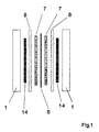
- the cell element of a cell of the invention comprises a pair of bipolar plates (1), a pair of collectors (14), a pair of gasket-frames (8), a pair of electrocatalytic electrodes (7) and an ion exchange membrane (6).
- the bipolar plate (1) is made of a metal plate which may have a flat surface in the area of contact with the collector (14).
- the peripheral frame area of the bipolar plate (1) is provided with holes (2) and optionally with distribution channels (3) for the inlet and outlet of the gases, holes (4) for the passage of the tie-rods (not shown in the figure) and optionally internal ducts (5) for the passage of a suitable cooling means.
- the dimensions of the bipolar plate are therefore dictated by the need to contain a certain active area of membrane (6) and electrodes (7) with the relevant collectors (14), as well as the holes (2, 4) and channels (3).
- the main characteristic of the bipolar plates of the present invention is the possibility of being produced in a great number of pieces with reasonable costs by cutting of commercial sheets or by casting in suitable molds, without any further mechanical flattening of the surface.
- the bipolar plates may be made of aluminum, titanium or alloys thereof, without the need for an electroconductive protective film. This last aspect will be illustrated in further details in the following description. Obviously other metals or alloys that may be used are niobium, tantalum, stainless steels, also high-alloys steels, nickel-chromium alloys, although less cost-effective and heavier due to the higher specific density of these materials.
- the construction material is aluminum or alloys thereof
- the high thermal conductivity permits to withdraw the heat produced during operation of the cell by cooling of the peripheral part of the bipolar plates only.
- the peripheral part is suitably enlarged and the heat removal may be carried out by forced circulation of air or other cooling means (not shown in the figures).
- the bipolar plates (1) made in aluminum or alloys thereof are not to be provided with internal ducts (5), with much simpler construction and a substantial reduction of the costs.
- the gasket-frames (8) comprise holes (9) for inlet and outlet of the reactants and products, fitting with the holes (2) of the bipolar plates (1), and optionally holes (10) for the passage of the tie-rods.
- the holes (10) are not necessary in a possible alternative embodiment where the corners are rounded off.
- the holes (9) are connected to suitable channels (11) cut out in the thickness of the gasket-frame and directed, coupled with channels (3), to uniformly distribute and collect the reactants and the products inside the cell.
- the products outlet should be localized in the lower part to permit an easier purging of the condensate water which may be formed in the cell during operation.
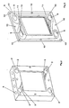
- the two faces of the gasket-frame may be non equivalent as, while the one in contact with the electrodes (7) and the membrane (6) may be flat, the one in contact with the bipolar plates is provided with channels (11) as aforementioned and with ribs (12), that is linear protrusions directed to ensure the necessary sealing to prevent gases from venting outside or mixing inside the cell.
- the sealing on the electrode side is ensured by the intrinsic resiliency of each gasket-frame/membrane pair.
- the gasket-frame is made of an elastomeric castable material. The required resiliency must be sufficient to permit a safe sealing under non-excessive mechanical load to avoid that deformation under compression may obstruct channels (3) and (11) and that the membrane be excessively stressed in the peripheral area.
- the thickness of the gasket-frame is dictated not only by mechanical considerations but also by the need to define an internal space available for the passage of gas.
- the gasket-frame of figs. 3 and 4 is further provided with a step (13) along the inside border to permit a ready housing of the electrode (7) and at the same time ensure a good protection of the membrane (6) from possible irregularities along the periphery of the collectors (14), such as residual peaks or burrs from the cutting of the pieces having the desired dimensions from commercial sheets.
- Fig. 4 shows in more detail the assembly made of gasket-frame (8)/collector (14)/electrode (7).
- the collectors (14) of the present invention are directed to provide at the same time for:
- the collector (14) is represented by a network with a surface provided with terminal sections (15), the efficiency of which has been demonstrated by electric resistance measurements carried out on assemblies simulating a cell element of the cell of the invention comprising two planar plates in aluminum alloy obtained by casting without any further mechanical finish, two collectors made in nickel, 2 mm thick, having a number of voids equal to 100/cm2 (average dimension of the voids : 1 mm), two electrodes commercialized under the trade name of ELAT by E-TEK, U.S.A., holding inbetween a Nafion(R) 117 membrane supplied by Du Pont, U.S.A.
- the measured electrical resistances were in the range of 100-5 milliohm/cm2, with pressures of 0.1-80 kg/cm2 respectively applied to the aluminum plates.
- the measured values are kept constant even maintaining the assembly in steam atmosphere at 100°C, as it may happen during real operation.
- the electrodes of the invention As the deformability of the collectors of the invention is relatively small at the pressure normally applied to the bipolar plates (in the order of some percent fractions of the thickness), it may be assumed that also the electrodes contribute to compensating the planarity deviations of the bipolar plates. In particular, to maintain the stresses on the membranes within acceptable values, the electrodes must exhibit a significant deformability. For this reason, it has been found that the best results in terms of absence of mechanical damages to the membranes are obtained when the electrodes comprise a deformable layer, such as carbon cloth.
- the bipolar plates may be of both the grooved and flat type, the last one being preferred in view of the substantially lower manufacturing cost. As regards the structure of the collector of fig.
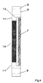
- this tridimensional network may be obtained starting from an expanded foam having open cells in plastic material, such as polyurethane, which is initially pre-treated to obtain a certain electrical conductivity (for example vacuum metallizing or metal deposition by means of electroless baths as known in the art or pyrolysis under inert atmosphere or vacuum to form carbonaceous material, optionally partially graphitized).
- the material, thus pretreated is then subjected to galvanic deposition of the desired metal or alloy, for example nickel, copper or alloys thereof with other metals, up to obtaining the desired thickness.
- the voids of the material have dimensions comprised between 0.1 and 3 mm and the diameter of the metal wires advantageously varies from 0.01 to 1 mm.
- the thickness of the collector indicates the terminal sections of the metal wires which, as above illustrated, ensure for a multiplicity of contact points with a high localized pressure in the small areas represented by the cross-sections of such terminal sections.
- the thickness of the collector is given by the thickness of the gasket-frame decreased by the thickness of the electrode.
- the thickness of the collector is generally comprised between 0.5 and 5 mm and more preferably between 1 and 2 mm.
- the network of fig. 5 is described in EP publication 0266312.A1 which claims its use as an expanded electrode for electrolysis of aqueous diluted solutions of metal ions and in U.S. Patent 4,657,650 which describes its application as the external electrical contact for the connection of elementary cells in an electrolyzer.
- the tridimensional network (reticulated material) according to the present invention may also be used in connection with a metal mesh or graphitized carbon mesh interposed between the reticulated material and the electrode/membrane structure.
- the mesh which may be particularly fine (for example meshes apertures smaller than 1 mm), ensures for the necessary multiplicity of contact points with the electrodes, while the reticulated material may be more freely selected, for example with particularly large voids in order to allow for the maximum percolation of the water which may have condensated inside.
- the use of the mesh permits further to ensure a higher protection of the membrane in the case the reticulated material presents a surface with particularly enhanced spikes.
- the collector of the present invention is simply made of one or more superimposed meshes, made of woven metal wire indicatively having mesh apertures smaller than 3 mm, preferably smaller than 1 mm, in order to ensure for a multiplicity of contact points between the electrodes and the bipolar plates.
- High contact pressures, particularly useful on the bipolar plate side are obtained when the wire used for fabricating the meshes has a quadrangular cross-section but also other polygonal cross-sections may be used.
- the longitudinal edges of the wire, in the superimposed points form a particularly useful array of asperities which imprint the metal surface of the bipolar plate.
- An alternative embodiment of the mesh which is as well advantageous is represented by an expanded metal obtained by pre-cutting of thin sheets and subsequent expansion.
- a mesh is obtained with apertures having various forms, for example rhomboidal, the portions of the metal which define the mesh apertures being rotated with respect to the plane of the sheet itself. Therefore when the expanded metal sheet is pressed against planar surfaces, the peaks of said rotated portions of metal become the areas of contact.
- At least one pair of the above described meshes is used in order to provide for higher resiliency and deformability, permeability to gaseous reactants and percolation of the water condensate.
- the meshes may be characterized by different apertures, in particular a fine mesh size for the one in contact with the electrodes and a coarser mesh in contact with the bipolar plate.
- a further embodiment of the present invention foresees the concurrent use of the above described collectors of the invention and in particular the reticulated material on one membrane side and one or more meshes, optionally having different mesh sizes, on the other side.
- the collector of the present invention made either of reticulated material or of superimposed meshes may be used on one side of the membrane only, while on the other side a rigid, conductive and porous material is used, such as a sinterized metal layer. This must be sufficiently thin in order to comply with the profile of the bipolar plate, which is not perfectly planar, under the applied pressure.
- the void ratio and the dimensions of the pores of the sinterized metal layer must be of the type already described for the collectors of the invention in order to permit the flow of reactants and products, percolation of the water condensate and multiplicity of contact points with the electrodes and bipolar plates.
- the metal forming the collector of the present invention must resist possible aggressive conditions which may be particularly severe when the cell is fed with air on the positive pole compartments and/or with a mixture of carbon dioxide and hydrogen on the negative pole compartments. Under these conditions possible water condensates are acidic.
- the metal is stainless steel of the 18 chromium-10 nickel type, preferably high-alloy steel, nickel-chromium alloys, titanium, niobium, or other valve metals.
- the collectors may be optionally coated with an electroconductive protective film, for example made of platinum group metals or oxides thereof.
- the protective film may be made of conductive polymers of the type comprising intrinsically conductive materials such as polyacethylenes, polypyrroles, polyanylines or the like or plastic materials containing conductive powders (for example graphite powder). Figs.
- each pair of bipolar plates (1) in aluminum or other passivatable material or alloys thereof maintains pressed inside a pair of collectors (14) of the invention, a pair of electrodes (7) and a membrane (6).
- Said electrodes as known in the art, before insertion between the bipolar plates and the collectors, are bonded to the membrane under pressure and heating, possibly after applying to the surface of the electrodes a suspension or solution containing the polymer forming the membrane, with the aim to facilitate both the adhesion of the electrode to the membrane as well as the formation of a large area of triple contact between gas, membrane and catalytic particles of the electrodes.
- the bipolar plates and the collector of the invention do not produce any appreciable improvement of the cell performance with respect to the teachings of the prior art. Therefore, the advantages of the present invention in this case are limited to higher simplicity and lower production costs, in particular for the bipolar plates made of aluminum or other passivatable metals without any protective coating. It has been surprisingly found that the bipolar plates and the collectors of the present invention permit to obtain optimum cell performances also when the electrodes, contrary to what taught in the art, are not previously bonded to the membrane, which obviously permits to reduce the production costs and to limit the risk of damaging the delicate membranes.
- the multiplicity of contact points and the high pressure obtained on said points are capable of maintaining a high percentage of the area of the electrodes in intimate mechanical contact with the membrane.
- the number of catalytic particles embedded in the membrane surface is analogous in the case of the present invention with the electrodes only laying onto the membrane and in the case described in the prior art with the electrodes bonded to the membrane.
- collectors consisting in undulated sheets or simply grooved bipolar plates, as known in the art, the performances are acceptable only when the electrodes are bonded to the membrane.
- the contact areas under sufficiently high pressure are limited only to the crossing points of the grooves or undulations and therefore involve a limited portion of the electrodes surface, which is the only one to be kept in contact with the membrane.
- the contact pressure with the membrane is nil and during operation the differential expansion of the membrane and the electrodes may bring to separation of the surfaces. This remaining portion, therefore, does not contribute in any way to the performance of the cell.
- the optimum results obtained according to the present invention with electrodes not bonded to the membrane are probably due also to a second characteristic of the collectors, that is deformability and residual resiliency under compression.
- This characteristic permits in fact to compensate for the small deviations from planarity of the planar bipolar plates not subjected to mechanical flattening of the surface.
- the compensation of planarity defects permits to maintain a uniformly distributed contact over all the surface of the bipolar plates, of the electrodes and membranes, ensuring thus optimum performances by a homogenous distribution of current.
- the electrodes (7) have a deformable structure.
- Suitable layers are made of carbon cloth or paper, optionally graphitized. The carbon cloth is preferred in view of the higher deformability and flexibility which facilitates handling and assembling into the cell.
- Products of this type containing platinum as the catalyst and polytetrafluoroethylene as the polymeric component are commercialized by various companies, for example E-TEK, U.S.A. under the trade name of ELAT. These products may be utilized as such or after painting with a suspension or paint containing a ionic polymer similar to that forming the membrane.
- Further types of porous layers are made of metal sinterized layers or fine screens or multilayer clothes, for example made of various types of stainless steels, high-alloyed steels, or alloys of nickel, chromium and titanium. Generally multilayer clothes are best preferred in view of their deformability.
- the above layers when made of a multi-layered cloth, may act at the same time as collectors and electrodes. In this case, the aforementioned suspension containing the electrocatalytic particles is applied only to the surface to be put in contact with the membrane.
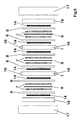
- Fig. 6 describes the assembly made of a multiplicity of cell elements of fig. 1 to form the cell of the invention, comprising the bipolar plates (1), collectors (14), electrodes (7), gasket-frames (8), ion exchange membranes (6), end-plates (18), pressure plates (17).
- the bipolar plates (1) are provided with external connections (16) which, once connected, permit to short-circuit two or more bipolar plates of the cell elements in the case of malfunctioning.
- bipolar plates provided with recesses of suitable form. This type of action permits the safe operation of the cell comprising a high number of cell elements connected in electrical series and it is therefore extremely helpful under a practical point of view.
- Example 1 The same test of Example 1, characterized by utilizing electrodes of the type G and collectors of the type R (sinterized material) was repeated after having made the bipolar plates, end plates and collectors hydrophobic by immersion in a suspension of polytetrafluoroethylene (commercialized by Du Pont under the trade name of Teflon 30N) followed by thermal treatment at 150°C.
- the voltages measured under the same testing conditions of Example 1 resulted comprised between 0,55 and 0,65 Volts. This improvement may be ascribed to the lower tendency of the sinterized material to retain water formed by condensation during operation.
- Example 2 The same cell of Example 1, characterized by the the presence of electrodes of the type G and collectors of the type L was subjected to repeated shortcircuiting of the second cell element by connecting by means of clamps the external connections indicated by reference numeral 16 in fig. 1
- the average voltages of the other cell elements did not change during the shortcircuiting periods and the shortcircuited cell element shortly reached the normal voltage once the clamps were disconnected.
- the maximum voltage between the bipolar plates of the shortcircuited cell element during shortcircuiting resulted in the range of 20-30 mV.
- Two fuel cells were made of three cell elements comprising bipolar plates and end plates provided with grooves directed to act as current distributors and consisting respectively of graphite and aluminum alloy of the type UNI 5076.
- the bipolar plates and terminal plates were further provided with internal ducts for cooling.
- the grooves were oriented in order to be crossed at 90° for each pair of facing sides of the bipolar and end plates.
- the electrodes were of the type G of Example 1 and the membranes were of the type Nafion(R) 117.
- the fuel cell equipped with bipolar plates and terminal plates in graphite and with the electrodes bonded to the membrane was operated under the same conditions as in Example 1 and resulted characterized by the best average voltages referred to the cell elements measured in the various conditions reported in Table 1 (0.7 Volts).
- the same fuel cell, provided with electrodes of the type G not bonded to the membrane showed quite unsatisfactory average voltages, comprised between 0.5 - 0.55 Volts, thus demonstrating that only the collectors of the invention, with their multiplicity of contact points, are capable of ensuring a satisfactory and extended continuity between the surfaces of the membranes and those of the electrodes, when these are not previously bonded.
- the fuel cell comprising grooved bipolar and end plates in aluminum alloy and electrodes of the type G bonded to the membrane, showed quite satisfactory performances at the beginning of the test.
- the voltages rapidly decreased to low values (0.4 Volts) in about a hundred hours, thus demonstrating that only the collectors of the invention are capable of maintaining the contact resistance within negligible values with time.
- a further test was carried out with a fuel cell comprising grooved bipolar and end plates in aluminum alloy, electrodes of the type G (Example 1) not bonded to the membranes and collectors of the invention of the type M (Example 1). The voltage resulted satisfactory (0,60 - 0,65 Volts) and stable with time.
Abstract
Description
In the case of ion exchange membranes, the contact between the membranes themselves and the porous electrodes is necessarily influenced by the fact that the two components are solid substances and therefore the area of triple contact results limited to the areas of real physical contact. Therefore the capillarity phenomena which contribute in such a determinant way with the liquid electrolytes are not possible. As a consequence the consumption speed of hydrogen and oxygen is rather small. This problem is overcome by heat-pressing the porous electrodes made of electrocatalytic particles onto the membranes, as described in US patent 3,134,697. Further improvements have been obtained by adding electroconductive particles, polymeric binders and in particular materials capable of favouring the migration of protons as claimed in US patent 4,876,115.
However, notwithstanding these improvements and implementations, the ion exchange membrane fuel cells have not yet achieved an industrial success. One of the reasons for this difficulty resides in the fact that the designs of the membrane fuel cells known in the art have not given so far a satisfactory reply to the problems of safety and fabrication costs, bound to the types of materials used for the construction, as well as to the need for a mass production and the assembling simplicity. This situation is due to the fact that the design of the membrane fuel cell must solve an objectively complex technical problem, that is providing the anodes at the same time with a homogeneous distribution of both electric current and reactants, a complete contact with the membrane and an effective withdrawal of the heat produced by the inefficiencies of the system (overvoltages, ohmic drops). The design of the fuel cell of the prior art is usually based on the fact that the electrodes must constitute a unitary structure with the membrane, obtained as aforesaid by heat-pressing the various components. This unitary structure intrinsically ensures the best continuous contact between the membrane and the electrodes. On these bases, the design of the bipolar plates has been finalized to perform the other tasks of gas and electric current distribution and heat withdrawal. The best preferred geometry resulted to be a bipolar plate provided with grooves, in particular with the grooves of one side oriented at 90° with respect to the grooves of the other side, as described in US Patent 4,175,165. More particularly, the cathode (positive) compartment where water is formed and the presence of liquid condensate is more likely to occur, is characterized by the grooves being kept in the vertical direction to allow for the best draining. In the fuel cell, made by a multiplicity of cell elements, each of said cell elements comprises a unitary electrodes-membrane structure rigidly pressed between the two sides of the two adjacent bipolar plates. In particular, as the grooves are crossed at 90°, the areas with a remarkable contact pressure are those areas where the grooves are superimposed and more particularly they are formed by a matrix consisting of squares having a side equal to the width of the crest of the grooves and a pitch equal to the width of the "valleys" of the grooves. As a consequence the distribution of current and the withdrawal of heat, certainly localized in the areas of greater contact pressure, may be made sufficiently homogeneous only by using very thin grooves and increasing as much as possible the transversal electrical and thermal conductivity of the electrodes. Therefore, the production costs of the bipolar plates are rather high in consideration of the need to mechanically work the surfaces in an accurate way to obtain the grooves and to ensure the necessary planarity required by a substantially rigid system wherein the only element at least partially provided with resiliency is the electrodes/membrane structure. The type of required machining, scarcely compatible with a mass production, strongly limits the dimensions of the bipolar plates to values capable only of permitting the production of small-size electric power systems, such as necessary for electric transportation, but certainly too small for other important applications which foresee the on-site stationary generation of electric power, such as required for local electric generators for mechanical workshops. The need to limit the costs due to the machining has forced the choice towards materials capable of being molded or extruded, in particular mixtures of graphite and polymeric binders as clearly described in the aforementioned US Patent 4,175,165.
As the bipolar plates must exhibit a sufficient electrical and thermal conductivity, the content of polymeric binder mixed to the graphite has to be maintained to a minimum which however must be able to assure the necessary moldability. As a consequence the toughness of the bipolar plate is not too high, certainly not to be compared with that typical of metallic materials. Further, a permeability to gases, even if minimum, cannot be excluded. Therefore, obvious objections as to the intrinsic safety of fuel cells equipped with graphite bipolar plates arise relating to the resistance to mechanical shocks and the possible release of hydrogen, in particular when operating under pressure. On the other hand, the metals which are usually considered, that is titanium, niobium, tantalum (known as valve metals, that is capable of forming with time a protective oxide which is electrically insulating), stainless steels and superalloys, such as the various types of Hastelloy(R) grades are characterized by high cost, high specific densities and limited thermal and electrical conductivity. Further, at least the valve metals must be provided with an electroconductive coating capable of maintaining a low electrical resistivity, said need further increasing the already high costs. It is further possible that the design foreseeing grooves may bring to anomalous operation, as the distribution of gas takes place only longitudinally along the grooves, without any appreciable transversal mixing.
As regards the electrodes, the need for a high electrical and thermal transversal conductivity reduces the selection to a few types and the use of unitary electrodes/membrane structures involves a further production step of heat-pressing. This step is doubly expensive in terms of manpower and necessary equipment, such as high-power presses, with a controlled temperature of the plates and with quite strict planarity requirements.
A constructive modification disclosed by US patent 4,224,121 comprises the addition of one or more metal meshes between the grooved bipolar plate and the electrodes/membrane unitary structure. This arrangement may improve the electric current distribution if at least the mesh in contact with the surface of the electrodes has a fine mesh size, even if this does not accomplish the final purpose of a complete homogeneity in the distribution also at a microscale level. In fact, the privileged areas are those subjected to a higher contact pressure corresponding to the intersections of the grooves. The addition of a package comprising a certain number of meshes, furthermore, provides the system with a certain resiliency and thus the planarity of the bipolar plates is a less strict requirement.
A bipolar plate design which permits to avoid the complications of the mechanical working required for the grooves foresees the use of undulated sheets, optionally perforated, used for the electrical contact between the surfaces of the electrodes and those of the planar bipolar plates, as described in DE 4120359. The undulated sheets may be welded to the bipolar plates or to the surface of the electrodes or to both. In a simpler and less expensive embodiment, the undulated sheets are simply pressed between the bipolar plates and the unitary electrodes/membranes structures. In this last case the two sheets on the sides of each single electrodes/membrane structure must necessarily positioned crossing the respective undulations and the areas with a substantial contact pressure are those where the undulations are superimposed. The devices incorporating the above mentioned undulated sheets are substantially affected by the same shortcomings as discussed for the grooves concerning the current and gas distribution, and more severe shortcomings as regards the heat removal considering the reduced thickness of the sheets necessary to ensure for a certain resiliency. It is also evident that the use of undulated sheets requires that electrodes and membrane form unitary structures which may be obtained as above illustrated by heat pressing.
A further construction solution described by the prior art foresees the use of porous sheets of sinterized metal, directed to act at the same time as current and gas distributors. In this case the cell element results to be formed by the unitary electrodes/membrane structure pressed between two sheets of sinterized metal, in turn pressed between the two planar bipolar plates, as described in DE 4027655.C.1.
In an alternative embodiment, the unitary structure is formed by a membrane and one electrode only; the second electrode is applied as an electrocatalytic coating onto the surface of a sinterized metal sheet. The cell element is therefore formed by the electrode/membrane unitary structure, a first sheet of sinterized metal in contact with said electrode, and a second sheet of sinterized metal having an electrocatalytic coating applied on one side thereof in contact with the face of the membrane without the electrode, the whole package inserted between two bipolar plates.
As the sinterized metal sheets are substantially rigid, the unavoidable loss of planarity of the bipolar plates may be only compensated by deformations of the membrane, which is the weaker element from a mechanical resistance standpoint. The membrane consequently results strongly stressed and may give rise to defects, in particular the presence of geometrical local irregularities, such as protruding peaks of the sinterized metal sheet and internal porosities of the membrane itself. This negative behaviour may be avoided only with a particularly accurate mechanical flattening of the surfaces of the bipolar plates. Further, the void ratio of the sinterized metal sheets is normally low and therefore the flow of gases through said sheets involves high pressure drops. As a consequence, the sinterized metal sheets may be used as current distributors to substitute the meshes of US Patent 4,224,121 but not as gas distributors. Therefore it is still necessary to use bipolar plates provided with grooves, with all the aforementioned problems connected with the mechanical working and the relevant costs.
The two faces of the gasket-frame may be non equivalent as, while the one in contact with the electrodes (7) and the membrane (6) may be flat, the one in contact with the bipolar plates is provided with channels (11) as aforementioned and with ribs (12), that is linear protrusions directed to ensure the necessary sealing to prevent gases from venting outside or mixing inside the cell. The sealing on the electrode side is ensured by the intrinsic resiliency of each gasket-frame/membrane pair. For this reason the gasket-frame is made of an elastomeric castable material. The required resiliency must be sufficient to permit a safe sealing under non-excessive mechanical load to avoid that deformation under compression may obstruct channels (3) and (11) and that the membrane be excessively stressed in the peripheral area. The thickness of the gasket-frame is dictated not only by mechanical considerations but also by the need to define an internal space available for the passage of gas. The gasket-frame of figs. 3 and 4 is further provided with a step (13) along the inside border to permit a ready housing of the electrode (7) and at the same time ensure a good protection of the membrane (6) from possible irregularities along the periphery of the collectors (14), such as residual peaks or burrs from the cutting of the pieces having the desired dimensions from commercial sheets.
The collectors (14) of the present invention are directed to provide at the same time for:
- a multiplicity of contact points with the electrodes to minimize the energy dispersions connected to excessively long transversal paths of electric current inside the electrodes;
- low values of the contact resistance with the surface of the bipolar plates preferably made of passivatable materials such as aluminum, titanium and alloys thereof, without protective electroconductive films;
- heat transmission from the electrodes-membrane structures to the bipolar plates (1) optionally provided with ducts (5) where a cooling means flows;
- longitudinal flow of reactants with small pressure drop and uniform distribution on the whole surface of the electrodes (7) due to the large possibility of transversal mixing;
- easy drain of liquid water formed by condensation inside the collector during operation;
- deformability with sufficient residual resiliency under compression, as required to compensate unavoidable planarity defects of the various components of the cell, in particular the bipolar plates which ideally are not subjected to precision mechanical finish of the surface. A certain degree of residual resiliency is also necessary to maintain under constant pressure the electrode/membrane structures to compensate the thermal expansion of the various components during start-up, shut down and electric load variations.
Preferably these mattresses are metal-wire fabrics or screens wherein the wires form a series of coils, waves, or crimps or other undulating contours. More preferably the mattress consists of a series of helicoidal cylindrical spirals of wire whose coils are mutually wound with the one of the adjacent spiral in an intermeshed or interlooped relationship.
In the present case it has been found that for the best performance the voids of the network must be such as to leave marks with dimensions in the range of 0.1-3 mm on a pressure sensitive paper while the pressures applied to the bipolar plates are indicatively comprised between 0.1 and 10 kg/cm2. In an alternative solution, the tridimensional network may be further characterized by a surface containing the terminal sections of at least part of the metal wires: this feature permits to obtain high localized pressures in very close limited-area points and therefore low values of the contact resistance.
Further, as already said, the bipolar plates may be advantageously used as such after casting or cutting from industrial sheets, without any need of subsequent mechanical flattening. This result is probably ensured by the deformability of the collector and by its residual resiliency, which permits to compensate for possible deviations from planarity, typical of unprocessed production pieces. As the deformability of the collectors of the invention is relatively small at the pressure normally applied to the bipolar plates (in the order of some percent fractions of the thickness), it may be assumed that also the electrodes contribute to compensating the planarity deviations of the bipolar plates. In particular, to maintain the stresses on the membranes within acceptable values, the electrodes must exhibit a significant deformability. For this reason, it has been found that the best results in terms of absence of mechanical damages to the membranes are obtained when the electrodes comprise a deformable layer, such as carbon cloth. The bipolar plates may be of both the grooved and flat type, the last one being preferred in view of the substantially lower manufacturing cost. As regards the structure of the collector of fig. 5, this tridimensional network may be obtained starting from an expanded foam having open cells in plastic material, such as polyurethane, which is initially pre-treated to obtain a certain electrical conductivity (for example vacuum metallizing or metal deposition by means of electroless baths as known in the art or pyrolysis under inert atmosphere or vacuum to form carbonaceous material, optionally partially graphitized). The material, thus pretreated, is then subjected to galvanic deposition of the desired metal or alloy, for example nickel, copper or alloys thereof with other metals, up to obtaining the desired thickness. The voids of the material have dimensions comprised between 0.1 and 3 mm and the diameter of the metal wires advantageously varies from 0.01 to 1 mm. Reference numeral (15) in fig. 5 indicates the terminal sections of the metal wires which, as above illustrated, ensure for a multiplicity of contact points with a high localized pressure in the small areas represented by the cross-sections of such terminal sections. The thickness of the collector, as will be clear from fig. 1, is given by the thickness of the gasket-frame decreased by the thickness of the electrode. The thickness of the collector is generally comprised between 0.5 and 5 mm and more preferably between 1 and 2 mm. The network of fig. 5 is described in EP publication 0266312.A1 which claims its use as an expanded electrode for electrolysis of aqueous diluted solutions of metal ions and in U.S. Patent 4,657,650 which describes its application as the external electrical contact for the connection of elementary cells in an electrolyzer.
Optionally, the tridimensional network (reticulated material) according to the present invention may also be used in connection with a metal mesh or graphitized carbon mesh interposed between the reticulated material and the electrode/membrane structure. In this double-layer structure of the collector, the mesh, which may be particularly fine (for example meshes apertures smaller than 1 mm), ensures for the necessary multiplicity of contact points with the electrodes, while the reticulated material may be more freely selected, for example with particularly large voids in order to allow for the maximum percolation of the water which may have condensated inside. The use of the mesh permits further to ensure a higher protection of the membrane in the case the reticulated material presents a surface with particularly enhanced spikes.
In a further embodiment, the collector of the present invention is simply made of one or more superimposed meshes, made of woven metal wire indicatively having mesh apertures smaller than 3 mm, preferably smaller than 1 mm, in order to ensure for a multiplicity of contact points between the electrodes and the bipolar plates. High contact pressures, particularly useful on the bipolar plate side, are obtained when the wire used for fabricating the meshes has a quadrangular cross-section but also other polygonal cross-sections may be used. In this case the longitudinal edges of the wire, in the superimposed points, form a particularly useful array of asperities which imprint the metal surface of the bipolar plate. An alternative embodiment of the mesh which is as well advantageous is represented by an expanded metal obtained by pre-cutting of thin sheets and subsequent expansion. In this way a mesh is obtained with apertures having various forms, for example rhomboidal, the portions of the metal which define the mesh apertures being rotated with respect to the plane of the sheet itself. Therefore when the expanded metal sheet is pressed against planar surfaces, the peaks of said rotated portions of metal become the areas of contact. At least one pair of the above described meshes is used in order to provide for higher resiliency and deformability, permeability to gaseous reactants and percolation of the water condensate. For this last instance, the meshes may be characterized by different apertures, in particular a fine mesh size for the one in contact with the electrodes and a coarser mesh in contact with the bipolar plate.
Further, the collector of the present invention made either of reticulated material or of superimposed meshes may be used on one side of the membrane only, while on the other side a rigid, conductive and porous material is used, such as a sinterized metal layer. This must be sufficiently thin in order to comply with the profile of the bipolar plate, which is not perfectly planar, under the applied pressure. The void ratio and the dimensions of the pores of the sinterized metal layer must be of the type already described for the collectors of the invention in order to permit the flow of reactants and products, percolation of the water condensate and multiplicity of contact points with the electrodes and bipolar plates.
The metal forming the collector of the present invention must resist possible aggressive conditions which may be particularly severe when the cell is fed with air on the positive pole compartments and/or with a mixture of carbon dioxide and hydrogen on the negative pole compartments. Under these conditions possible water condensates are acidic. Taking into account both this possibility and the fact that the operating temperature is higher than the room temperature, most advantageously the metal is stainless steel of the 18 chromium-10 nickel type, preferably high-alloy steel, nickel-chromium alloys, titanium, niobium, or other valve metals. The collectors may be optionally coated with an electroconductive protective film, for example made of platinum group metals or oxides thereof. Alternatively the protective film may be made of conductive polymers of the type comprising intrinsically conductive materials such as polyacethylenes, polypyrroles, polyanylines or the like or plastic materials containing conductive powders (for example graphite powder).
Figs. 1 and 6 clearly illustrate that each pair of bipolar plates (1) in aluminum or other passivatable material or alloys thereof maintains pressed inside a pair of collectors (14) of the invention, a pair of electrodes (7) and a membrane (6). Said electrodes, as known in the art, before insertion between the bipolar plates and the collectors, are bonded to the membrane under pressure and heating, possibly after applying to the surface of the electrodes a suspension or solution containing the polymer forming the membrane, with the aim to facilitate both the adhesion of the electrode to the membrane as well as the formation of a large area of triple contact between gas, membrane and catalytic particles of the electrodes. If the membranes and the electrodes are bonded together to form a unitary structure, the bipolar plates and the collector of the invention however do not produce any appreciable improvement of the cell performance with respect to the teachings of the prior art. Therefore, the advantages of the present invention in this case are limited to higher simplicity and lower production costs, in particular for the bipolar plates made of aluminum or other passivatable metals without any protective coating.
It has been surprisingly found that the bipolar plates and the collectors of the present invention permit to obtain optimum cell performances also when the electrodes, contrary to what taught in the art, are not previously bonded to the membrane, which obviously permits to reduce the production costs and to limit the risk of damaging the delicate membranes. Without binding the validity of the present invention to any particular theory, it may be assumed that the multiplicity of contact points and the high pressure obtained on said points, typical of the above mentioned collectors, are capable of maintaining a high percentage of the area of the electrodes in intimate mechanical contact with the membrane. As a consequence, the number of catalytic particles embedded in the membrane surface (triple contact area) is analogous in the case of the present invention with the electrodes only laying onto the membrane and in the case described in the prior art with the electrodes bonded to the membrane. Conversely, it has been found that with collectors consisting in undulated sheets or simply grooved bipolar plates, as known in the art, the performances are acceptable only when the electrodes are bonded to the membrane. As above discussed, with these collectors the contact areas under sufficiently high pressure are limited only to the crossing points of the grooves or undulations and therefore involve a limited portion of the electrodes surface, which is the only one to be kept in contact with the membrane. In the remaining portion of electrode surface, the contact pressure with the membrane is nil and during operation the differential expansion of the membrane and the electrodes may bring to separation of the surfaces. This remaining portion, therefore, does not contribute in any way to the performance of the cell. These considerations are to explain why the prior art describes bonding of the electrodes to the membrane as an essential factor for a good performance of the cells with collectors provided with grooves or undulations.
The optimum results obtained according to the present invention with electrodes not bonded to the membrane are probably due also to a second characteristic of the collectors, that is deformability and residual resiliency under compression. This characteristic permits in fact to compensate for the small deviations from planarity of the planar bipolar plates not subjected to mechanical flattening of the surface.
The compensation of planarity defects permits to maintain a uniformly distributed contact over all the surface of the bipolar plates, of the electrodes and membranes, ensuring thus optimum performances by a homogenous distribution of current. As already said, in order to maximize the deformability property, the electrodes (7) have a deformable structure. They are made of a porous deformable layer of conductive material, onto which a suspension is applied by spraying or brushing or any similar technique. The suspension comprises a liquid vehicle, powders of electrocatalytic and electroconductive materials and polymeric binder, optionally comprising ionic groups, with hydrophobic or hydrophilic characteristics, directed to control the wettability of the system. The porous layer is then dried and subjected to a thermal treatment directed to mechanically stabilize the applied material. Suitable layers are made of carbon cloth or paper, optionally graphitized. The carbon cloth is preferred in view of the higher deformability and flexibility which facilitates handling and assembling into the cell. Products of this type, containing platinum as the catalyst and polytetrafluoroethylene as the polymeric component are commercialized by various companies, for example E-TEK, U.S.A. under the trade name of ELAT. These products may be utilized as such or after painting with a suspension or paint containing a ionic polymer similar to that forming the membrane. Further types of porous layers are made of metal sinterized layers or fine screens or multilayer clothes, for example made of various types of stainless steels, high-alloyed steels, or alloys of nickel, chromium and titanium. Generally multilayer clothes are best preferred in view of their deformability. In another embodiment, the above layers, when made of a multi-layered cloth, may act at the same time as collectors and electrodes. In this case, the aforementioned suspension containing the electrocatalytic particles is applied only to the surface to be put in contact with the membrane.
The following examples, which do not constitute in any case a limitation of the objects of the present invention, will better explain the present invention. For convenience sake the examples have been limited to the case of the fuel cells.
- dimensions of the electrodes and collectors : 10x10 cm2
- membranes: Nafion(R) 117, supplied by Du Pont, USA
- membrane active area : 10x10 cm2
- moulded gasket-frames, having inside dimensions of 10x10 cm2 and outside dimensions of 20x20 cm2, a thickness of 2 mm, provided with holes (9) and (10), channels (11), ribs (12) 0,1 mm high, internal step (13) 0,5 mm deep with an external dimension of 11x11 cm2, as shown in fig. 3. Construction material: Hytrel(R) commercialized by Du Pont, USA;
- bipolar plates and end plates with external dimensions of 20x20 cm2, provided with holes (2) and (4) and other characteristics as specified hereunder.
- feed to the anode (negative) compartments made of pure hydrogen at 2 atm, pre-heated and pre-humidified at 70°C in an external saturator, the flow rate being doubled with respect to the stoichiometry of the reaction;
- feed to the cathode (positive) compartments made of purified air at 2,1 atm, pre-heated and pre-humidified at 50°C in an external saturator with a triple flow rate with respect to the stoichiometry of the reaction;
- operating temperature : 80°C
- total current: 50 Ampere, corresponding to a current density on the active area of the electrodes equal to 5000 Ampere/m2
- total operation time for each test as indicated here after, but in any case comprised between 300 and 400 hours, with start up and shut down at the beginning and at the end of each working day.
- A. bipolar plates and end plates in aluminum alloy, UNI
5076 type (Italian Standards), obtained by pressure
die-casting having a thickness of 5 mm, provided with
internal ducts for cooling (5) made of stainless steel
of the 18 chromium-10 nickel type with an internal
diameter of 3 mm and channels (3) as illustrated in
fig. 1
e 2 - B. same bipolar plates and end plates as in A, the only difference being the construction material, titanium instead of aluminum alloys.
- C. bipolar plates and end plates made of aluminum alloy, Anticorodal 100 TA16 type (Italian Standards) obtained by cutting from commercial sheets having a thickness of 3 mm, without inside cooling ducts (5) and channels (3). In this case the external dimension of the plates was increased to 30x30 cm2 to permit cooling by forced air
- D. same bipolar plates as in C, but with the contact surface with the collectors coated with a chromium film obtained by galvanic deposition;
- E. same bipolar plates as in C, but with the contact surface with the collectors coated with a film of a polymeric conductive film belonging to the group of polyanyline.
- F. electrodes made of flexible conductive carbon cloth, coated on one side thereof with a film containing electrocatalytic platinum particles supported onto active carbon and a polymeric binder and on the other side with a hydrophobic porous and conductive film based on polytetrafloroethylene, supplied by E-TEK, USA under the trade name of ELAT, 0,5 mm thick, with a platinum load of 0,5 mg/cm2;
- G. same electrodes as in F, with the further application
of a polymer similar to that of the membrane on the
side containing the catalyst, applied by brushing or
spraying with a solution of a perfluorinated polymer
containing sulphonic groups, commercialized by
Solution Technology, USA under the trade name of
Nafion Solution 5% - H. same electrodes as in G, wherein the flexible carbon cloth is substituted for a conductive carbon rigid graphite paper supplied by Toray, Japan, under the commercial trade name of TGHP 030;
- I. same electrodes as in G, wherein the flexible carbon
cloth is substituted for a multilayer cloth in
stainless steel of the
type 18 chromium-10 nickel-2 molybdenum; - L. collectors in reticulated material as shown in fig. 5, made of an alloy of 50 chromium - 50 nickel, having an average diameter of the pores of about 0.2 mm and a 2 mm thickness. Materials of this type are currently supplied by different companies and are conventionally called metal foam;
- M. same collectors as in L, having an average diameter of the pores of about 1 mm
- N. same collectors as in L, having an average diameter of the pores of about 3 mm;
- O. collectors consisting of 3 superimposed meshes made of 18 chromium-10 nickel stainless steel wire having a diameter of 0.3 mm forming meshes with apertures of 0,5x0,5 mm;
- P. collectors consisting of 2 titanium expanded sheets having diamond shaped apertures with the major dimension respectively of 1 mm (expanded sheet on the electrode side) and 3 mm (expanded sheet on the bipolar plate side) obtained from a sheet 0.5 mm thick and coated with a platinum layer 0.3 microns thick formed by galvanic deposition;
- Q. collectors consisting in a multilayer cloth obtained from a metal wire having a diameter of 0.15 mm made in stainless steel of the 18 chromium-10 nickel-2 molybdenum type, 2 mm thick under compression, commercialized by Costacurta, Italy;
- R. collectors made of a layer of sinterized metal such as
stainless steel of the
type 18 chromium-10 nickel, 2 mm thick.
The temperature of the plates was controlled by forced circulation of demineralized water at 75°C.
| electrode | F | G | H | I |
| collector | ||||
| L | 0,65 | 0,7 | 0,7 | == |
| | 0,6 | 0,7 | 0,6 | == |
| | 0,6 | 0,7 | 0,6 | == |
| N | 0,55 | 0,65 | 0,6 | == |
| | 0,6 | 0,7 | 0,65 | == |
| | 0,6 | 0,7 | 0,6 | == |
| | 0,6 | 0,7 | 0,65 | 0,7 |
| R | 0,45 | 0,5 | 0,45 | == |
| L + | 0,6 | 0,7 | 0,6 | == |
| L + | 0,6 | 0,65 | 0,6 | == |
- the data obtained with electrodes bonded to the membrane (line L*) represent a comparison with the prior art. It is clear that pre-treatment of the electrodes with a polymer solution similar to that of the membrane allows for a definite improvement of the performances.
- the multiplicity of contact points per unity of surface area is instrumental for an optimum performance. The tridimensional network of the type N, characterized by pores with an average dimension of 3 mm, is in fact constantly characterized by insufficient voltages.
- the deformability of the collectors and electrodes is a key factor as demonstrated by the unsatisfactory voltages obtained with the sinterized materials (line R) and the rigid graphite paper used as a substrate for the electrodes (column H).
- in the case of collectors made of sinterized material (line R), the unsatisfactory performances are also due at least to a partial flooding of the compartments (probably the cathode positive compartments) due to the water condensate formed during operation and retained by capillarity in the small pores of the sinterized material;
- the optimum and stable voltage values, typical of all the tests, demonstrate that the electrical resistance between the collectors of the invention and the planar bipolar plates of aluminum alloys, without an electroconductive protective coating, is extremely reduced. This result is quite surprising in consideration of the fact that aluminum and alloys thereof are known to become coated with a natural electrically insulating oxide, in particular under heat in the presence of steam (typical operating condition of the fuel cell). A confirmation of this conclusion is given by the voltages quite similar to those obtained with bipolar plates coated with a chromium protective film (type D) and conductive polymeric material (type E).
The grooves were oriented in order to be crossed at 90° for each pair of facing sides of the bipolar and end plates.
The electrodes were of the type G of Example 1 and the membranes were of the type Nafion(R) 117. The fuel cell equipped with bipolar plates and terminal plates in graphite and with the electrodes bonded to the membrane was operated under the same conditions as in Example 1 and resulted characterized by the best average voltages referred to the cell elements measured in the various conditions reported in Table 1 (0.7 Volts). However, the same fuel cell, provided with electrodes of the type G not bonded to the membrane, showed quite unsatisfactory average voltages, comprised between 0.5 - 0.55 Volts, thus demonstrating that only the collectors of the invention, with their multiplicity of contact points, are capable of ensuring a satisfactory and extended continuity between the surfaces of the membranes and those of the electrodes, when these are not previously bonded.
As said above, the fuel cell, comprising grooved bipolar and end plates in aluminum alloy and electrodes of the type G bonded to the membrane, showed quite satisfactory performances at the beginning of the test. However, the voltages rapidly decreased to low values (0.4 Volts) in about a hundred hours, thus demonstrating that only the collectors of the invention are capable of maintaining the contact resistance within negligible values with time.
As a confirmation of this fact a further test was carried out with a fuel cell comprising grooved bipolar and end plates in aluminum alloy, electrodes of the type G (Example 1) not bonded to the membranes and collectors of the invention of the type M (Example 1). The voltage resulted satisfactory (0,60 - 0,65 Volts) and stable with time. Further, this embodiment resulted particularly efficient for draining the water condensate formed in the cathode (positive) compartments where the grooves of the bipolar and end plates where positioned in the vertical direction.
Various modifications of the cell of the invention may be made and it has to be understood that the present invention is limited only as defined in the appended claims.
Claims (23)
- A cell element for a fuel cell or for electrolysis of pure water or for concentration of hydrogen and oxygen from gaseous reactants comprisinga pair of bipolar or end plates (1,18) provided with holes (2) for feeding reactants and removing products and residual reactants, said bipolar or end plates (1,18) being made of metal or metal alloys capable of forming a protective oxide selected from the group consisting of aluminum, titanium, zirconium, niobium , tantalum and alloys thereof, stainless steels, high-alloy steels, nickel-chromium alloys,an ion exchange membrane (6),a pair of electrocatalytic porous electrodes (7) comprising a deformable layer apt to prevent mechanical damage to said membrane (6),a pair of gasket frames (8),a pair of porous current collectors (14) provided with a multiplicity of contact points for the electrical contact between said bipolar or end plates (1,18) and said electrodes (7), at least one of said porous current collectors (14) consisting of a resilient material, having voids with dimensions comprised between 0.1 and 3 mm and having a residual deformability and resiliency under a pressure comprised between 0.1 and 80 kg/cm2,said multiplicity of contact points of the current collectors (14) allows for the rupture or the prevention of growth of the protective oxide of said bipolar or end plates (1,18) under said pressure.
- The element of claim 1 wherein said collector (14) provided with residual deformability and resiliency is a tridimensional network of metal wires, the surface of said network containing the terminal sections (15) of at least part of said wires.
- The element of claim 2 wherein said tridimensional network has a porosity at least equal to 50% and a diameter of the metal wires comprised between 0.01 and 1 mm.
- The element of anyone of claims 1 to 3 wherein said collector (14) provided with residual deformability and resiliency consists in at least two superimposed meshes.
- The element of claim 4 wherein said meshes have a different mesh size with a finer mesh for the mesh in contact with the electrodes (7) and a coarser mesh for the mesh in contact with the bipolar or end plates (1, 18).
- The element of anyone of claims 4 and 5 wherein the meshes are selected in the group consisting of woven metal wires or expanded metal sheets.
- The element of claim 6 wherein said metal wires have a polygonal cross-section.
- The element of anyone of claims 1 to 3 wherein said collector (14) provided with residual deformability and resiliency consists in a mattress made of interwoven metal helicoidal coils or a multilayer cloth.
- The element of anyone of claims 1 to 8 wherein both collectors (14) are provided with residual deformability and resiliency or wherein one collector (14) has residual deformability and resiliency and the other collector (14) is a rigid porous sheet, preferably a sinterized metal layer.
- The element of anyone of claims 1 to 9 wherein said collectors (14) have a thickness comprised between 0.5 and 5 mm.
- The element of anyone of claims 1 to 3 or 8 to 10 wherein said collectors (14) further comprise a fine metal mesh facing said electrodes (7).
- The element of anyone of claims 1 to 11 wherein said collectors (14) are made of a corrosion-resistant material selected from the group consisting of stainless steels, high-alloy steels, nickel-chromium alloys.
- The element of anyone of claims 1 to 12 wherein said collectors (14) and said bipolar or end plates (1, 18) are hydrophobic.
- The element of anyone of claims 1 to 13 wherein said bipolar or end plates (1, 18) have a planar surface,wherein said bipolar or end plates (1, 18) preferably are obtained by molding or cutting of commercial sheets without further finish of the surface, or have a grooved surface,wherein said bipolar or end plates (1, 18) preferably are further provided with channels (3) for the distribution and for the removal of the reactants and products,wherein said bipolar or end plates (1, 18) preferably are further provided with internal ducts (5) for cooling with a gaseous or liquid means,wherein the external dimension of said bipolar or end plates (1, 18) preferably is increased to permit cooling with a gaseous or liquid means.
- The element of one of claims 1 to 14 wherein said bipolar or end plates (1, 18) are made from a material selected from the group consisting of aluminum, titanium, zirconium, niobium , tantalum and alloys thereof and wherein the contact resistance between said bipolar or end plates (1, 18) and said collectors (14) is comprised between 100 and 5 mΩ·cm2 under said pressure.
- The element of anyone of claims 1 to 15 wherein said gasket-frames (8) are made of castable elastomeric material and comprise holes (9) for the distribution and the removal of the reactants and products and a step (13) for the housing of said electrodes (7) and ribs (12) for sealing and separation of the reactants and products.
- The element of anyone of claims 1 to 16 wherein said electrodes (7) are made of a porous, conductive layer provided with a surface containing a catalyst and a surface containing hydrophobic material.
- The element of anyone of claims 1 to 17, wherein said deformable layer is a flexible carbon cloth, a carbon paper or a flexible cloth of corrosion resistant metal selected from the group consisting of stainless steels, high-alloy steels, nickel-chromium alloys.
- The element of one of claims 17 or 18 wherein said electrodes (7) are further provided with a coating of a polymer having ion exchange characteristics applied onto the surface containing the catalyst.
- The element of anyone of claims 1 to 19 wherein said electrodes (7) are not bonded to the membrane before assembling of the electrochemical cell.
- The element of anyone of claims 1 to 19 wherein said electrodes (7) are bonded to the membrane before assembling of the electrochemical cell and form a unitary structure.
- The element of anyone of claims 1 to 21 wherein said bipolar or end plates (1, 18) are provided with external connections or recesses (16) suitable for short-circuiting.
- A fuel cell comprising the cell element of one of claims 1 to 22.
Applications Claiming Priority (2)
| Application Number | Priority Date | Filing Date | Title |
|---|---|---|---|
| ITMI930857 | 1993-04-30 | ||
| ITMI930857A IT1270878B (en) | 1993-04-30 | 1993-04-30 | IMPROVED ELECTROCHEMISTRY CELL USING ION EXCHANGE MEMBRANES AND METAL BIPOLAR PLATES |
Publications (2)
| Publication Number | Publication Date |
|---|---|
| EP0629015A1 EP0629015A1 (en) | 1994-12-14 |
| EP0629015B1 true EP0629015B1 (en) | 2001-12-05 |
Family
ID=11365953
Family Applications (1)
| Application Number | Title | Priority Date | Filing Date |
|---|---|---|---|
| EP94106748A Expired - Lifetime EP0629015B1 (en) | 1993-04-30 | 1994-04-29 | Electrochemical cell provided with ion exchange membranes and bipolar plates |
Country Status (16)
| Country | Link |
|---|---|
| US (3) | US5482792A (en) |
| EP (1) | EP0629015B1 (en) |
| JP (1) | JP2953555B2 (en) |
| CN (1) | CN1076887C (en) |
| AT (1) | ATE210339T1 (en) |
| AU (1) | AU674931B2 (en) |
| BR (1) | BR9401641A (en) |
| CA (1) | CA2121455C (en) |
| CZ (1) | CZ98694A3 (en) |
| DE (1) | DE69429304T2 (en) |
| DK (1) | DK0629015T3 (en) |
| ES (1) | ES2169050T3 (en) |
| FI (1) | FI941932A (en) |
| IT (1) | IT1270878B (en) |
| RU (1) | RU2126569C1 (en) |
| SK (1) | SK50694A3 (en) |
Families Citing this family (248)
| Publication number | Priority date | Publication date | Assignee | Title |
|---|---|---|---|---|
| US5773162A (en) * | 1993-10-12 | 1998-06-30 | California Institute Of Technology | Direct methanol feed fuel cell and system |
| US6703150B2 (en) * | 1993-10-12 | 2004-03-09 | California Institute Of Technology | Direct methanol feed fuel cell and system |
| US5599638A (en) * | 1993-10-12 | 1997-02-04 | California Institute Of Technology | Aqueous liquid feed organic fuel cell using solid polymer electrolyte membrane |
| US5961795A (en) * | 1993-11-22 | 1999-10-05 | E. I. Du Pont De Nemours And Company | Electrochemical cell having a resilient flow field |
| US6042702A (en) * | 1993-11-22 | 2000-03-28 | E.I. Du Pont De Nemours And Company | Electrochemical cell having a current distributor comprising a conductive polymer composite material |
| JPH0817451A (en) * | 1994-06-29 | 1996-01-19 | Aisin Seiki Co Ltd | Fuel cell |
| JPH08130023A (en) * | 1994-10-27 | 1996-05-21 | Aisin Seiki Co Ltd | Fuel cell |
| DE69520752D1 (en) * | 1994-12-17 | 2001-05-23 | Univ Loughborough | GALVANIC CELL AND FUEL CELL ARRANGEMENTS |
| WO1996035002A1 (en) * | 1995-05-01 | 1996-11-07 | E.I. Du Pont De Nemours And Company | Electrochemical cell having a current distributor comprising a conductive polymer composite material |
| WO1996035001A1 (en) * | 1995-05-01 | 1996-11-07 | E.I. Du Pont De Nemours And Company | Electrochemical cell having a resilient flow field |
| DE19533773A1 (en) * | 1995-09-12 | 1997-03-13 | Basf Ag | Plate stack cell |
| AU713035B2 (en) * | 1995-10-06 | 1999-11-18 | Dow Chemical Company, The | Flow field structures for membrane electrode assemblies of fuel cells |
| US5702755A (en) * | 1995-11-06 | 1997-12-30 | The Dow Chemical Company | Process for preparing a membrane/electrode assembly |
| US6312845B1 (en) | 1995-10-06 | 2001-11-06 | The Dow Chemical Company | Macroporous flow field assembly |
| US5624769A (en) | 1995-12-22 | 1997-04-29 | General Motors Corporation | Corrosion resistant PEM fuel cell |
| US5882810A (en) * | 1996-03-08 | 1999-03-16 | The Dow Chemicalcompany | Active layer for membrane electrode assembly |
| AUPN876896A0 (en) * | 1996-03-18 | 1996-04-18 | Ceramic Fuel Cells Limited | An electrical interconnect for a planar fuel cell |
| US6054228A (en) * | 1996-06-06 | 2000-04-25 | Lynntech, Inc. | Fuel cell system for low pressure operation |
| IT1284072B1 (en) * | 1996-06-26 | 1998-05-08 | De Nora Spa | ELECTROCHEMICAL DIAPHRAGM CELL FITTED WITH GASEOUS DIFFUSION ELECTRODES CONTACTED BY SMOOTH AND POROUS METALLIC CURRENT HOLDERS |
| US5868918A (en) * | 1996-09-26 | 1999-02-09 | Air Products And Chemicals, Inc. | Method for separating oxygen from an oxygen-containing gas |
| US5798187A (en) * | 1996-09-27 | 1998-08-25 | The Regents Of The University Of California | Fuel cell with metal screen flow-field |
| IT1284887B1 (en) * | 1996-10-03 | 1998-05-22 | De Nora Spa | METHOD OF EXCLUSION OF A MALFUNCTIONING ELEMENTARY CELL OF AN ELECTROLYZER OR OF A MEMBRANE ELECTROCHEMICAL GENERATOR |
| US6037075A (en) * | 1996-11-26 | 2000-03-14 | United Technologies Corporation | Electrically non-conductive plate structures and high pressure electrochemical cell devices employing same |
| WO1998033224A1 (en) | 1997-01-22 | 1998-07-30 | Siemens Aktiengesellschaft | Fuel cell and use of iron-based alloys in the construction of fuel cells |
| US6146780A (en) * | 1997-01-24 | 2000-11-14 | Lynntech, Inc. | Bipolar separator plates for electrochemical cell stacks |
| US6287431B1 (en) | 1997-03-21 | 2001-09-11 | Lynntech International, Ltd. | Integrated ozone generator system |
| US5989407A (en) * | 1997-03-31 | 1999-11-23 | Lynntech, Inc. | Generation and delivery device for ozone gas and ozone dissolved in water |
| US6576096B1 (en) | 1998-01-05 | 2003-06-10 | Lynntech International, Ltd. | Generation and delivery device for ozone gas and ozone dissolved in water |
| KR20010006129A (en) * | 1997-04-07 | 2001-01-26 | 그래햄 이. 테일러 | Electrolysis of alkali metal halide brines using oxygen cathode systems |
| US5976726A (en) | 1997-05-01 | 1999-11-02 | Ballard Power Systems Inc. | Electrochemical cell with fluid distribution layer having integral sealing capability |
| EP0996988A1 (en) * | 1997-05-13 | 2000-05-03 | Loughborough University Innovations Limited | Current distributors of sintered metals and fuel cells using them |
| IT1293814B1 (en) * | 1997-08-04 | 1999-03-10 | De Nora Spa | ION EXCHANGE MEMBRANE FUEL CELL WITH PERIPHERAL COOLING |
| WO1999041796A1 (en) * | 1998-02-10 | 1999-08-19 | H2-Interpower Gmbh | Fuel cell with solid electrolyte and planar structure |
| US6232010B1 (en) | 1999-05-08 | 2001-05-15 | Lynn Tech Power Systems, Ltd. | Unitized barrier and flow control device for electrochemical reactors |
| US6071635A (en) * | 1998-04-03 | 2000-06-06 | Plug Power, L.L.C. | Easily-formable fuel cell assembly fluid flow plate having conductivity and increased non-conductive material |
| US6007933A (en) * | 1998-04-27 | 1999-12-28 | Plug Power, L.L.C. | Fuel cell assembly unit for promoting fluid service and electrical conductivity |
| WO2000001025A1 (en) * | 1998-06-30 | 2000-01-06 | Matsushita Electric Industrial Co., Ltd. | Solid polymer electrolyte fuel cell |
| JP3644385B2 (en) | 1998-07-10 | 2005-04-27 | 株式会社豊田中央研究所 | Fuel cell separator and method for producing the same |
| JP2000106197A (en) * | 1998-09-30 | 2000-04-11 | Aisin Takaoka Ltd | Fuel cell and separator for fuel cell |
| US6261710B1 (en) | 1998-11-25 | 2001-07-17 | Institute Of Gas Technology | Sheet metal bipolar plate design for polymer electrolyte membrane fuel cells |
| JP2000164225A (en) * | 1998-11-25 | 2000-06-16 | Toshiba Corp | Separator of solid polymer electrolyte fuel cell and its manufacture |
| US6602631B1 (en) | 1999-01-26 | 2003-08-05 | Lynntech Power Systems, Ltd. | Bonding electrochemical cell components |
| US6280866B1 (en) | 1999-02-23 | 2001-08-28 | Northern Research & Engineering Corporation | Fuel cell flow distributor design for improving durability and performance |
| US6284401B1 (en) * | 1999-04-19 | 2001-09-04 | George A. Marchetti | Thin graphite bipolar plate with associated gaskets and carbon cloth flow-field for use in an ionomer membrane fuel cell |
| ITMI991090A1 (en) * | 1999-05-18 | 2000-11-18 | De Nora Spa | HUMIDIFYING DEVICE FOR POLYMER MEMBRANE FUEL CELLS |
| US6503654B2 (en) * | 1999-05-19 | 2003-01-07 | George A. Marchetti | Thin graphite bipolar plate with associated gaskets and carbon cloth flow-field for use in an ionomer membrane fuel cell |
| GB9915925D0 (en) * | 1999-07-08 | 1999-09-08 | Univ Loughborough | Flow field plates |
| FR2799308B1 (en) * | 1999-09-30 | 2002-01-25 | Sorapec | IMPROVEMENTS ON BIPOLAR COLLECTORS FOR PEM-TYPE FUEL CELLS |
| US6383677B1 (en) | 1999-10-07 | 2002-05-07 | Allen Engineering Company, Inc. | Fuel cell current collector |
| US6864007B1 (en) | 1999-10-08 | 2005-03-08 | Hybrid Power Generation Systems, Llc | Corrosion resistant coated fuel cell plate with graphite protective barrier and method of making the same |
| US6649031B1 (en) | 1999-10-08 | 2003-11-18 | Hybrid Power Generation Systems, Llc | Corrosion resistant coated fuel cell bipolar plate with filled-in fine scale porosities and method of making the same |
| US6315958B1 (en) | 1999-11-10 | 2001-11-13 | Wisconsin Alumni Research Foundation | Flow cell for synthesis of arrays of DNA probes and the like |
| US6777126B1 (en) | 1999-11-16 | 2004-08-17 | Gencell Corporation | Fuel cell bipolar separator plate and current collector assembly and method of manufacture |
| IT1314256B1 (en) * | 1999-12-03 | 2002-12-06 | Nora Fuel Cells S P A De | POLYMERIC MEMBRANE FUEL CELL BATTERY. |
| US6372376B1 (en) * | 1999-12-07 | 2002-04-16 | General Motors Corporation | Corrosion resistant PEM fuel cell |
| DE19960815A1 (en) * | 1999-12-16 | 2001-07-19 | Siemens Ag | Fuel cell block |
| US7153409B2 (en) * | 1999-12-16 | 2006-12-26 | Proton Energy Systems, Inc. | Electrochemical cell system and method of operation |
| WO2001045192A1 (en) * | 1999-12-16 | 2001-06-21 | Proton Energy Systems, Inc. | Low gravity electrochemical cell |
| WO2001054218A2 (en) * | 2000-01-19 | 2001-07-26 | Manhattan Scientifics, Inc. | Fuel cell stack with cooling fins and use of expanded graphite in fuel cells |
| US6828054B2 (en) | 2000-02-11 | 2004-12-07 | The Texas A&M University System | Electronically conducting fuel cell component with directly bonded layers and method for making the same |
| US6770394B2 (en) * | 2000-02-11 | 2004-08-03 | The Texas A&M University System | Fuel cell with monolithic flow field-bipolar plate assembly and method for making and cooling a fuel cell stack |
| WO2001059862A2 (en) * | 2000-02-11 | 2001-08-16 | The Texas A & M University System | Electroconductive fuel cell component with directly bonded layers and method for making same |
| US6602626B1 (en) | 2000-02-16 | 2003-08-05 | Gencell Corporation | Fuel cell with internal thermally integrated autothermal reformer |
| EP1293006A2 (en) | 2000-03-17 | 2003-03-19 | Allen Engineering Company, Inc. | Fuel cell stack assembly |
| DE10015360B4 (en) * | 2000-03-28 | 2006-11-23 | Ballard Power Systems Inc., Burnaby | Separator unit for electrolysis cells and fuel cells |
| EP1269557A1 (en) * | 2000-03-31 | 2003-01-02 | Ingersoll-Rand Energy Systems Corporation | Fuel cell flow distributor design for improving durability and performance |
| EP1160900A3 (en) * | 2000-05-26 | 2007-12-12 | Kabushiki Kaisha Riken | Embossed current collector separator for electrochemical fuel cell |
| US20020045081A1 (en) * | 2000-07-05 | 2002-04-18 | Masaaki Nanaumi | Electrolyte membrane/electrode assembly of solid polymer electrolyte fuel cell |
| SE522666C2 (en) * | 2000-07-07 | 2004-02-24 | Volvo Ab | Gas distribution element for fuel cells, fuel cell and method for producing a gas distribution element |
| AU2001285436A1 (en) | 2000-08-14 | 2002-02-25 | World Properties Inc. | Thermosetting composition for electrochemical cell components and methods of making thereof |
| US20020022382A1 (en) * | 2000-08-18 | 2002-02-21 | Franklin Jerrold E. | Compliant electrical contacts for fuel cell use |
| US6531238B1 (en) | 2000-09-26 | 2003-03-11 | Reliant Energy Power Systems, Inc. | Mass transport for ternary reaction optimization in a proton exchange membrane fuel cell assembly and stack assembly |
| AU2002225675A1 (en) * | 2000-11-22 | 2002-06-03 | Powercell Corporation | Bipolar plate and method of manufacturing same |
| JP2004525748A (en) * | 2000-12-12 | 2004-08-26 | ウォーター・ピック・インコーポレーテッド | Apparatus and method for producing and providing ozonated water |
| US7138203B2 (en) * | 2001-01-19 | 2006-11-21 | World Properties, Inc. | Apparatus and method of manufacture of electrochemical cell components |
| WO2002080295A2 (en) * | 2001-01-19 | 2002-10-10 | World Properties Inc. | Apparatus and method for electrochemical cell components |
| US6824910B2 (en) * | 2001-01-24 | 2004-11-30 | The Regents Of The University Of California | Co-flow planar SOFC fuel cell stack |
| ITMI20010458A1 (en) * | 2001-03-06 | 2002-09-06 | Nuvera Fuel Cells Europ Srl | SHORT CIRCUITATION METHOD OF A FAULTY ELEMENTARY ELECTROCHEMISTRY CELL OF A FILTER-PRESS STRUCTURE |
| RU2183370C1 (en) * | 2001-04-12 | 2002-06-10 | ЗАО Индепендент Пауэр Технолоджис "ИПТ" | Fuel cell module and battery built around it |
| US20050095492A1 (en) * | 2001-05-15 | 2005-05-05 | Hydrogenics Corporation | Fuel cell stack |
| US6852439B2 (en) * | 2001-05-15 | 2005-02-08 | Hydrogenics Corporation | Apparatus for and method of forming seals in fuel cells and fuel cell stacks |
| US6878477B2 (en) * | 2001-05-15 | 2005-04-12 | Hydrogenics Corporation | Fuel cell flow field plate |
| FI20011044A (en) * | 2001-05-17 | 2002-11-18 | Reijo Varila | Electrolytic cell, cell structure and uses of cell structure |
| US6884531B2 (en) * | 2001-05-21 | 2005-04-26 | Saudi Arabian Oil Company | Liquid hydrocarbon based fuels for fuel cell on-board reformers |
| US6620542B2 (en) | 2001-05-30 | 2003-09-16 | Hewlett-Packard Development Company, L.P. | Flex based fuel cell |
| JPWO2003012903A1 (en) * | 2001-07-31 | 2004-11-25 | 住友精密工業株式会社 | Fuel cell |
| US6781249B2 (en) | 2001-08-29 | 2004-08-24 | Hewlett-Packard Development Company, L.P. | Retrofittable power supply |
| JP3860733B2 (en) * | 2001-09-17 | 2006-12-20 | 新光電気工業株式会社 | Fuel cell |
| ITMI20012342A1 (en) * | 2001-11-08 | 2003-05-08 | Nuvera Fuel Cells Europ Srl | METHOD FOR REUSING COLLECTORS / CURRENT DISTRIBUTORS OF A DIAPHRAGM ELECTROCHEMICAL GENERATOR |
| US6811918B2 (en) * | 2001-11-20 | 2004-11-02 | General Motors Corporation | Low contact resistance PEM fuel cell |
| DE10158771C2 (en) * | 2001-11-23 | 2003-09-18 | Reinz Dichtungs Gmbh & Co Kg | The fuel cell system |
| KR100429685B1 (en) * | 2001-12-17 | 2004-05-03 | 한국과학기술연구원 | Gas- distributing plate for compact polymer electrolyte membrane fuel cell and separator plate using the said gas-distributing plate |
| DE10162871A1 (en) * | 2001-12-20 | 2003-07-10 | Forschungszentrum Juelich Gmbh | Bipolar graphite plate |
| KR100448168B1 (en) * | 2001-12-27 | 2004-09-10 | 현대자동차주식회사 | A preparing method of Membrane-Electrode-Gasket Assembly for fuel cell |
| EP1327492A1 (en) * | 2002-01-15 | 2003-07-16 | N.V. Bekaert S.A. | Porous metal stack for fuel cells or electrolysers |
| EP1328030A1 (en) * | 2002-01-15 | 2003-07-16 | N.V. Bekaert S.A. | Metal stack for fuel cells or electrolysers |
| EP1482585B1 (en) * | 2002-03-04 | 2012-06-20 | Mitsubishi Materials Corporation | Solid oxide type fuel cell and separator |
| DE10216306B4 (en) * | 2002-04-14 | 2008-06-12 | Sgl Carbon Ag | Method for producing a contact plate for an electrochemical cell and its uses |
| ITMI20020869A1 (en) | 2002-04-23 | 2003-10-23 | Nuvera Fuel Cells Europ Srl | ELECTROCHEMICAL GENERATOR AND REDUCED DIAPHRAGM MEMBRANE |
| US6828057B2 (en) * | 2002-04-29 | 2004-12-07 | Energy Conversion Devices, Inc. | Fuel cell with framed electrodes |
| US6926986B2 (en) * | 2002-04-29 | 2005-08-09 | Energy Conversion Devices | Fuel cell with encapsulated electrodes |
| US6989216B2 (en) * | 2002-04-29 | 2006-01-24 | Texaco Ovonic Fuel Cell Llc | Fuel cell with overmolded electrode assemblies |
| US7241334B2 (en) * | 2002-05-23 | 2007-07-10 | Columbian Chemicals Company | Sulfonated carbonaceous materials |
| WO2003103082A2 (en) * | 2002-05-31 | 2003-12-11 | Lynntech, Inc. | Electrochemical cell and bipolar assembly for an electrochemical cell |
| ITMI20021338A1 (en) * | 2002-06-17 | 2003-12-17 | Nuvera Fuel Cells Europ Srl | MEMBRANE ELECTROCHEMICAL GENERATOR WITH DIRECT INJECTION OF LIQUID WATER IN GASEOUS AGENTS |
| US7270906B2 (en) * | 2002-06-24 | 2007-09-18 | Delphi Technologies, Inc. | Solid-oxide fuel cell module for a fuel cell stack |
| DE10233982B4 (en) * | 2002-07-25 | 2007-08-16 | Forschungszentrum Jülich GmbH | Bipolar plate for a fuel cell and fuel cell stack |
| US6838202B2 (en) * | 2002-08-19 | 2005-01-04 | General Motors Corporation | Fuel cell bipolar plate having a conductive foam as a coolant layer |
| TWI241732B (en) * | 2002-09-25 | 2005-10-11 | E I Du Pont Canada Company | Mesh reinforced fuel cell separator plate |
| JP4396091B2 (en) * | 2002-09-30 | 2010-01-13 | 三菱マテリアル株式会社 | Gas diffusion layer for fuel cells |
| US7005209B1 (en) | 2002-10-04 | 2006-02-28 | The Texas A&M University System | Fuel cell stack assembly |
| US7001687B1 (en) | 2002-10-04 | 2006-02-21 | The Texas A&M University System | Unitized MEA assemblies and methods for making same |
| US20040229108A1 (en) * | 2002-11-08 | 2004-11-18 | Valdez Thomas I. | Anode structure for direct methanol fuel cell |
| JP3793141B2 (en) * | 2002-11-14 | 2006-07-05 | 株式会社日立製作所 | Polymer electrolyte fuel cell and separator |
| GB0227180D0 (en) * | 2002-11-21 | 2002-12-24 | Omnagen Ltd | Improvements in or relating to a fuel cell |
| US7282291B2 (en) * | 2002-11-25 | 2007-10-16 | California Institute Of Technology | Water free proton conducting membranes based on poly-4-vinylpyridinebisulfate for fuel cells |
| US7736783B2 (en) * | 2002-12-04 | 2010-06-15 | Lynntech, Inc. | Very thin, light bipolar plates |
| US20040168910A1 (en) * | 2002-12-04 | 2004-09-02 | Craig Andrews | Self-aligning components for electrochemical cells |
| US6887613B2 (en) * | 2002-12-04 | 2005-05-03 | General Motors Corporation | Corrosion resistant PEM fuel cell |
| DE10260149A1 (en) * | 2002-12-20 | 2004-07-01 | BSH Bosch und Siemens Hausgeräte GmbH | Device for determining the conductivity of laundry, clothes dryer and method for preventing layer formation on electrodes |
| US7294425B2 (en) * | 2002-12-23 | 2007-11-13 | Semgreen, L.P. | Channel-less proton exchange membrane fuel cell |
| US6772617B1 (en) | 2003-01-24 | 2004-08-10 | Gencell Corporation | Method and apparatus for in-situ leveling of progressively formed sheet metal |
| US6793544B2 (en) * | 2003-02-05 | 2004-09-21 | General Motors Corporation | Corrosion resistant fuel cell terminal plates |
| US20040247990A1 (en) * | 2003-03-19 | 2004-12-09 | Campbell Stephen A. | Platinum alloy catalysts for electrochemical fuel cells |
| JP4441719B2 (en) * | 2003-03-20 | 2010-03-31 | 大日本印刷株式会社 | Fuel cell separator |
| US20040191603A1 (en) * | 2003-03-25 | 2004-09-30 | Kaiser Joseph G. | Clad metallic bipolar plates and electricity-producing systems and fuel cells using the same |
| US7282293B2 (en) * | 2003-04-15 | 2007-10-16 | Mti Microfuel Cells Inc. | Passive water management techniques in direct methanol fuel cells |
| US7407721B2 (en) * | 2003-04-15 | 2008-08-05 | Mti Microfuel Cells, Inc. | Direct oxidation fuel cell operating with direct feed of concentrated fuel under passive water management |
| WO2004102709A1 (en) * | 2003-05-16 | 2004-11-25 | Hydrogenics Corporation | Flow field plate for a fuel cell and fuel cell assembly incorporating the flow field plate |
| DE10323881A1 (en) * | 2003-05-26 | 2004-12-23 | Siemens Ag | Contact device and fuel cell stack or fuel cell block with such a contact device |
| US7655337B2 (en) * | 2003-06-27 | 2010-02-02 | Ultracell Corporation | Micro fuel cell thermal management |
| US6942941B2 (en) * | 2003-08-06 | 2005-09-13 | General Motors Corporation | Adhesive bonds for metalic bipolar plates |
| US7396559B2 (en) * | 2003-08-11 | 2008-07-08 | General Motors Corporation | Method of making an electrically conductive element for use in a fuel cell |
| US20050037935A1 (en) * | 2003-08-11 | 2005-02-17 | Abd Elhamid Mahmoud H. | Composition and method for surface treatment of oxidized metal |
| US20050069749A1 (en) * | 2003-08-15 | 2005-03-31 | David Frank | Flow field plate arrangement |
| US7358005B2 (en) * | 2003-09-18 | 2008-04-15 | General Electric Company | Methods and apparatus for isolating solid oxide fuel cells |
| WO2005028715A1 (en) * | 2003-09-22 | 2005-03-31 | Hydrogenics Corporation | System and method for alarm recovery for an electrolyzer cell module |
| EP1678348A4 (en) * | 2003-09-22 | 2007-06-13 | Hydrogenics Corp | Electrolyzer cell arrangement |
| US20050186458A1 (en) | 2003-09-22 | 2005-08-25 | Ali Rusta-Sallehy | Electrolyzer cell stack system |
| US20050064270A1 (en) * | 2003-09-24 | 2005-03-24 | Marianowski Leonard G. | Fuel cell bipolar separator plate |
| ITMI20031881A1 (en) * | 2003-10-01 | 2005-04-02 | Nuvera Fuel Cells Europ Srl | BIPOLAR SEPARATOR FOR BATTERY OF FUEL CELLS. |
| ITMI20031972A1 (en) * | 2003-10-14 | 2005-04-15 | Nuvera Fuel Cells Europ Srl | MEMBRANE FUEL CELL WITH STABLE OVER TIME OPERATION |
| JP4154315B2 (en) * | 2003-11-21 | 2008-09-24 | 本田技研工業株式会社 | Fuel cell |
| ITMI20032531A1 (en) * | 2003-12-19 | 2005-06-20 | Nuvera Fuel Cells Europ Srl | MEMBRANE COMBUSTION CELL POWERED IN |
| FR2866477B1 (en) * | 2004-02-17 | 2006-06-30 | Air Liquide | FUEL CELL ARCHITECTURE |
| US7150918B2 (en) * | 2004-02-27 | 2006-12-19 | General Motors Corporation | Bilayer coating system for an electrically conductive element in a fuel cell |
| JP4696456B2 (en) * | 2004-03-15 | 2011-06-08 | 日立電線株式会社 | Corrosion-resistant conductive composite material for fuel cell separator |
| GB2413002B (en) * | 2004-04-08 | 2006-12-06 | Intelligent Energy Ltd | Fuel cell gas distribution |
| DE102004028141C5 (en) * | 2004-06-10 | 2015-11-19 | Elcomax Membranes Gmbh | Membrane Electrode Module (MEA) for a fuel cell and fuel cell stack |
| JP4908778B2 (en) * | 2004-06-30 | 2012-04-04 | キヤノン株式会社 | Method for producing catalyst layer of polymer electrolyte fuel cell and method for producing polymer electrolyte fuel cell |
| US7569303B2 (en) | 2004-09-24 | 2009-08-04 | Hydrogenics Corporation | Membrane electrode assembly with modified catalyst layout |
| US7378177B2 (en) * | 2004-09-30 | 2008-05-27 | Proton Energy Systems, Inc. | Electrochemical cell bipolar plate |
| US7951510B2 (en) | 2004-11-11 | 2011-05-31 | GM Global Technology Operations LLC | Electroconductive polymer coating on electroconductive elements in a fuel cell |
| US7452623B2 (en) * | 2004-11-11 | 2008-11-18 | Proton Energy Systems, Inc. | Electrochemical cell bipolar plate with sealing feature |
| ITMI20042247A1 (en) | 2004-11-19 | 2005-02-19 | Nuvera Fuel Cells Europ Srl | ELECTRIC GENERATION SYSTEM INCLUDING FUEL CELLS WITH MEMBRANE POWERED BY DRIED GAS |
| TWI278138B (en) * | 2004-11-25 | 2007-04-01 | Toshiba Corp | Fuel cell |
| US7687176B2 (en) * | 2004-12-10 | 2010-03-30 | 3M Innovative Properties Company | Fuel cell |
| DE102005005116A1 (en) * | 2005-02-04 | 2006-08-10 | Forschungszentrum Jülich GmbH | Interconnector for high-temperature fuel cells |
| US7666386B2 (en) | 2005-02-08 | 2010-02-23 | Lynntech Power Systems, Ltd. | Solid chemical hydride dispenser for generating hydrogen gas |
| US20060257313A1 (en) * | 2005-02-17 | 2006-11-16 | Alan Cisar | Hydrolysis of chemical hydrides utilizing hydrated compounds |
| US20060210857A1 (en) * | 2005-03-15 | 2006-09-21 | David Frank | Electrochemical cell arrangement with improved mea-coolant manifold isolation |
| US20060210855A1 (en) * | 2005-03-15 | 2006-09-21 | David Frank | Flow field plate arrangement |
| US20060257555A1 (en) * | 2005-05-12 | 2006-11-16 | Brady Brian K | Sub-layer for adhesion promotion of fuel cell bipolar plate coatings |
| DE102005034616B4 (en) * | 2005-07-18 | 2008-07-03 | Elringklinger Ag | Fuel cell unit and fuel cell stack |
| US7919213B1 (en) * | 2005-08-09 | 2011-04-05 | Becker Rolf R | Fuel cell bipolar plate and composition therefore |
| KR100792138B1 (en) | 2005-10-27 | 2008-01-04 | 주식회사 엘지화학 | Method of preparing membrane electrode assembly |
| US7833645B2 (en) * | 2005-11-21 | 2010-11-16 | Relion, Inc. | Proton exchange membrane fuel cell and method of forming a fuel cell |
| US20080032174A1 (en) * | 2005-11-21 | 2008-02-07 | Relion, Inc. | Proton exchange membrane fuel cells and electrodes |
| JPWO2007069404A1 (en) * | 2005-12-16 | 2009-05-21 | 株式会社エクォス・リサーチ | Fuel cell electrode, fuel cell and fuel cell stack |
| JP5114950B2 (en) * | 2006-02-13 | 2013-01-09 | 日産自動車株式会社 | Battery module, assembled battery, and vehicle equipped with these batteries |
| US8133591B2 (en) * | 2006-06-27 | 2012-03-13 | GM Global Technology Operations LLC | Adhesion of polymeric coatings to bipolar plate surfaces using silane coupling agents |
| JP4876766B2 (en) | 2006-08-10 | 2012-02-15 | トヨタ自動車株式会社 | Fuel cell |
| DE102006040030B4 (en) * | 2006-08-23 | 2009-09-03 | Fraunhofer-Gesellschaft zur Förderung der angewandten Forschung e.V. | Stacking unit for a stack of electrochemical cells, stacking arrangement and method for producing a stacking unit |
| JP2008108456A (en) * | 2006-10-23 | 2008-05-08 | Equos Research Co Ltd | Electrode for fuel cell, cell of fuel cell, and stack of fuel cells |
| WO2008057318A1 (en) * | 2006-11-01 | 2008-05-15 | The Government Of The United States Of America, As Represented By The Secretary Of The Navy | Biological fuel cells with nanporous membranes |
| US8455155B2 (en) * | 2006-11-22 | 2013-06-04 | GM Global Technology Operations LLC | Inexpensive approach for coating bipolar plates for PEM fuel cells |
| TW200832800A (en) * | 2007-01-19 | 2008-08-01 | Coretronic Corp | Fuel cell |
| JP5125275B2 (en) * | 2007-02-05 | 2013-01-23 | トヨタ自動車株式会社 | Fuel cell and vehicle equipped with fuel cell |
| JP5275255B2 (en) * | 2007-02-06 | 2013-08-28 | ヌベラ・フュエル・セルズ・ヨーロッパ・ソチエタ・ア・レスポンサビリタ・リミタータ | Bipolar unit for a fuel cell provided with a porous current collector |
| US20080206615A1 (en) * | 2007-02-22 | 2008-08-28 | Paul Nicotera | Gas diffusion layer with controlled diffusivity over active area |
| JP2008243572A (en) * | 2007-03-27 | 2008-10-09 | Equos Research Co Ltd | Current collector and fuel cell |
| JP4323535B2 (en) * | 2007-04-26 | 2009-09-02 | クロリンエンジニアズ株式会社 | Water electrolysis equipment |
| US20080311448A1 (en) * | 2007-04-27 | 2008-12-18 | Arizona Board Of Regents For And On Behalf Of Arizona State University | High Temperature Polymer Electrolyte Membrane Fuel Cells |
| US8026020B2 (en) | 2007-05-08 | 2011-09-27 | Relion, Inc. | Proton exchange membrane fuel cell stack and fuel cell stack module |
| DE102007024225A1 (en) * | 2007-05-11 | 2008-11-13 | Deutsches Zentrum für Luft- und Raumfahrt e.V. | Support device for an electrochemical functional device, fuel cell module and method for producing a carrier device |
| US7732081B2 (en) * | 2007-05-23 | 2010-06-08 | Gm Global Technology Operations, Inc. | Hydrophilic/hydrophobic patterned surfaces and methods of making and using the same |
| US9293778B2 (en) | 2007-06-11 | 2016-03-22 | Emergent Power Inc. | Proton exchange membrane fuel cell |
| JP5270885B2 (en) * | 2007-09-05 | 2013-08-21 | 株式会社東芝 | Fuel electrode for solid oxide electrochemical cell, method for producing the same, and solid oxide electrochemical cell |
| FR2923086B1 (en) * | 2007-10-24 | 2010-12-10 | Commissariat Energie Atomique | INTEGRATED COMBUSTIBLE CELL ARCHITECTURE WITHOUT SEAL. |
| US8003274B2 (en) * | 2007-10-25 | 2011-08-23 | Relion, Inc. | Direct liquid fuel cell |
| TW200921975A (en) * | 2007-11-08 | 2009-05-16 | Univ Nat Central | Fuel cell with composite pole plate |
| US9614232B2 (en) * | 2007-12-28 | 2017-04-04 | Altergy Systems | Modular unit fuel cell assembly |
| JP5197022B2 (en) * | 2008-01-07 | 2013-05-15 | セイコーインスツル株式会社 | Fuel cell |
| JP2009187887A (en) * | 2008-02-08 | 2009-08-20 | Ngk Spark Plug Co Ltd | Fuel electrode collector, and solid electrolyte fuel cell |
| US8465629B2 (en) * | 2008-04-11 | 2013-06-18 | Christopher M. McWhinney | Membrane for electrochemical apparatus |
| JP5439740B2 (en) * | 2008-05-14 | 2014-03-12 | トヨタ自動車株式会社 | Fuel cell and fuel cell stack |
| JP5763533B2 (en) * | 2008-06-23 | 2015-08-12 | ヌヴェラ・フュエル・セルズ・インコーポレーテッド | Polymer electrolyte membrane fuel cell stack and bipolar plate assembly |
| WO2009157981A1 (en) * | 2008-06-23 | 2009-12-30 | Blanchet Scott C | Fuel cell with reduced mass transfer limitations |
| US8954862B1 (en) | 2008-10-01 | 2015-02-10 | Valador, Inc. | System and method for collaborative viewing of a four dimensional model requiring decision by the collaborators |
| TW201014930A (en) | 2008-10-09 | 2010-04-16 | Troika Internat Co Ltd | Hydrogen-oxygen electrolysis apparatus and dual-surface layer modified carbon fiber paper electrode thereof |
| US8889314B2 (en) * | 2009-01-13 | 2014-11-18 | GM Global Technology Operations LLC | Bipolar plate for a fuel cell stack |
| DE102010029966A1 (en) * | 2009-06-10 | 2010-12-16 | Wieland Kg | Improved electrocatalyst, fuel cell cathode and fuel cell |
| WO2011076342A1 (en) * | 2009-12-22 | 2011-06-30 | Topsoe Fuel Cell A/S | Manufacture and calibration process for an interconnect for a fuel cell or a fuel cell stack |
| US10581089B2 (en) * | 2010-03-11 | 2020-03-03 | Nuvera Fuel Cells, LLC | Open flow field fuel cell |
| CA2790538C (en) * | 2010-03-11 | 2018-04-17 | Nuvera Fuel Cells, Inc. | Fuel cell with electrode geometric area variance |
| WO2011150458A1 (en) * | 2010-06-01 | 2011-12-08 | The University Of Queensland | A fuel cell stack |
| TWI404259B (en) * | 2010-08-06 | 2013-08-01 | Univ Nat Chiao Tung | Fuel cell, sheet having penetrable electric conductivity and manufacturing thereof |
| CN102134726B (en) * | 2011-01-10 | 2014-04-16 | 清华大学 | Flat plate type solid oxide electrolytic cell pile with novel sealed structure |
| FR2975228B1 (en) | 2011-05-09 | 2013-11-22 | Commissariat Energie Atomique | FUEL CELL WITH INDIVIDUAL INJECTOR JOINTS |
| NO20111046A1 (en) * | 2011-07-20 | 2013-01-21 | Nel Hydrogen As | Print Item |
| US8671985B2 (en) | 2011-10-27 | 2014-03-18 | Pentair Residential Filtration, Llc | Control valve assembly |
| US9637397B2 (en) | 2011-10-27 | 2017-05-02 | Pentair Residential Filtration, Llc | Ion removal using a capacitive deionization system |
| US9010361B2 (en) | 2011-10-27 | 2015-04-21 | Pentair Residential Filtration, Llc | Control valve assembly |
| US8961770B2 (en) | 2011-10-27 | 2015-02-24 | Pentair Residential Filtration, Llc | Controller and method of operation of a capacitive deionization system |
| US9695070B2 (en) | 2011-10-27 | 2017-07-04 | Pentair Residential Filtration, Llc | Regeneration of a capacitive deionization system |
| JP5980524B2 (en) * | 2012-02-27 | 2016-08-31 | 株式会社バンテック | Electrolytic chamber, electrolytic cell unit, electrolytic cell stack, and hydrogen generator |
| RU2504868C2 (en) * | 2012-04-28 | 2014-01-20 | Открытое акционерное общество "Объединенная авиастроительная корпорация" | Fuel cell and fuel cell battery |
| EP2872754A4 (en) * | 2012-07-02 | 2016-03-02 | Arthur Jeffs | Hydrogen fuel assist device for an internal combustion engine and related methods |
| JP6356127B2 (en) * | 2012-08-17 | 2018-07-11 | ヌヴェラ・フュエル・セルズ,エルエルシー | Bipolar plate design for use in electrochemical cells |
| WO2014043651A2 (en) | 2012-09-14 | 2014-03-20 | Liquid Light, Inc. | High pressure electrochemical cell and process for the electrochemical reduction of carbon dioxide |
| EP2730680B1 (en) * | 2012-11-08 | 2016-04-13 | Siemens Aktiengesellschaft | Bipolar plate for an electrolyser, electrolyser and method for producing a bipolar plate |
| FR3008428B1 (en) * | 2013-07-11 | 2015-08-07 | Ceth² | SEAL FOR ELECTROLYSOR BATTERY AND ELECTROLYSIS BATTERY EQUIPPED WITH SUCH A SEAL |
| US9915004B2 (en) | 2013-07-19 | 2018-03-13 | Nuvera Fuel Cells, LLC | System and method for tuning an electrochemical cell stack |
| AT513501B1 (en) * | 2013-09-02 | 2014-05-15 | Abatec Group Ag | IR emitter with double glazing |
| BR112016030212A2 (en) * | 2014-06-27 | 2017-08-22 | Nuvera Fuel Cells Llc | ELECTROCHEMICAL CELL, FLOW FIELD AND OPEN POROUS FLOW FIELD MANUFACTURE METHOD FOR USE IN IT |
| AT515926B1 (en) * | 2014-07-18 | 2016-01-15 | Cellstrom Gmbh | End frame for flow battery |
| CN105576265A (en) * | 2014-10-28 | 2016-05-11 | 上海蓝蔚科技发展有限公司 | Method for processing bipolar plate gas runner in fuel cell reactor |
| KR101763382B1 (en) * | 2015-08-27 | 2017-08-02 | 한국에너지기술연구원 | Working electrode of cell for felt electrode characterization and cell for felt electrode characterization using the same |
| CN105586612A (en) * | 2015-11-10 | 2016-05-18 | 海安南京大学高新技术研究院 | Preparing method of conducting polymer-metal composite hybridization anticorrosive coating |
| RU2647841C2 (en) * | 2016-08-11 | 2018-03-21 | Публичное акционерное общество "Ракетно-космическая корпорация "Энергия" имени С.П. Королёва (ПАО "РКК "Энергия") | Water electrolyser and operation method thereof |
| CN106395997A (en) * | 2016-09-21 | 2017-02-15 | 见嘉环境科技(苏州)有限公司 | Multifunctional flowing type electrochemical reactor |
| BR112019008041A2 (en) * | 2016-10-21 | 2019-07-02 | Nantenergy Inc | corrugated fuel electrode |
| US10547061B2 (en) * | 2016-12-22 | 2020-01-28 | Plug Power Inc. | Fuel cell stack |
| JP6368389B1 (en) * | 2017-02-02 | 2018-08-01 | 日本特殊陶業株式会社 | Electrochemical reaction unit and electrochemical reaction cell stack |
| FR3062856B1 (en) * | 2017-02-14 | 2019-04-12 | AREVA H2Gen | ELECTROLYSER SPACER AND ELECTROLYSER EQUIPPED WITH SUCH A SPACER |
| JP7053162B2 (en) * | 2017-04-05 | 2022-04-12 | トヨタ自動車株式会社 | Stacked battery module |
| WO2018224448A1 (en) | 2017-06-07 | 2018-12-13 | Nv Bekaert Sa | Gas diffusion layer |
| DE102018211988A1 (en) * | 2018-07-18 | 2020-01-23 | Siemens Mobility GmbH | Fuel cell with protection against open circuit voltage |
| US11118141B2 (en) | 2018-12-21 | 2021-09-14 | Henkel IP & Holding GmbH | Use of alkoxylated polyamines to control rheology of unit dose detergent compositions |
| CN109904481A (en) * | 2019-01-18 | 2019-06-18 | 天津大学 | The cathode of solid oxide fuel cell metal foam runner optimizes structure |
| CN110112434A (en) * | 2019-05-16 | 2019-08-09 | 张国胜 | Bipolar plates and fuel cell pile and electricity generation system comprising the bipolar plates |
| US20230012017A1 (en) | 2019-12-20 | 2023-01-12 | Totalenergies Onetech | Tubular electrochemical separation unit and manufacturing method therefor |
| GB202100555D0 (en) * | 2021-01-15 | 2021-03-03 | Afc Energy Plc | Bipolar plate and resilent conduction member |
| WO2022244805A1 (en) * | 2021-05-20 | 2022-11-24 | 株式会社トクヤマ | Anion exchange membrane type aqueous electrolytic cell |
| AT524548B1 (en) * | 2021-08-13 | 2022-07-15 | H2i GreenHydrogen GmbH | Cell frame for an electrolytic cell |
| JP2022023996A (en) * | 2021-11-05 | 2022-02-08 | 東京瓦斯株式会社 | Electrochemical device |
| WO2023193057A1 (en) * | 2022-04-07 | 2023-10-12 | Hysata Pty Ltd | Stackable electro-synthetic or electro-energy cells |
| EP4343898A1 (en) * | 2022-09-21 | 2024-03-27 | iGas energy GmbH | Combination of porous transport layer and bipolar plate for electrochemical cells |
Family Cites Families (23)
| Publication number | Priority date | Publication date | Assignee | Title |
|---|---|---|---|---|
| US3134697A (en) * | 1959-11-03 | 1964-05-26 | Gen Electric | Fuel cell |
| FR1433469A (en) * | 1965-02-16 | 1966-04-01 | Thomson Houston Comp Francaise | Fuel cell improvements |
| FR1593242A (en) * | 1968-03-19 | 1970-05-25 | ||
| SU394873A1 (en) * | 1968-06-10 | 1973-08-22 | LOW-TEMPERATURE HYDROGEN-OXYGEN FUEL ELEMENT | |
| US3895960A (en) * | 1970-08-27 | 1975-07-22 | Westinghouse Electric Corp | Diffusion-bonded battery electrode plaques |
| DE2741956A1 (en) * | 1976-09-20 | 1978-03-23 | Gen Electric | ELECTROLYSIS OF SODIUM SULFATE USING AN ION EXCHANGE MEMBRANE CELL WITH SOLID ELECTROLYTE |
| US4175165A (en) * | 1977-07-20 | 1979-11-20 | Engelhard Minerals & Chemicals Corporation | Fuel cell system utilizing ion exchange membranes and bipolar plates |
| US4339314A (en) | 1979-02-23 | 1982-07-13 | Ppg Industries, Inc. | Solid polymer electrolyte and method of electrolyzing brine |
| GB2051870B (en) * | 1979-06-07 | 1983-04-20 | Asahi Chemical Ind | Method for electrolysis of aqueous alkali metal chloride solution |
| US4340452A (en) * | 1979-08-03 | 1982-07-20 | Oronzio deNora Elettrochimici S.p.A. | Novel electrolysis cell |
| IT1140510B (en) * | 1980-01-16 | 1986-10-01 | Oronzio De Nora Impianti | BIPOLAR ELECTROLIZER AND ELECTROLYSIS PROCEDURE OF ELECTROLYSIS OF HALIDE |
| EP0050373B1 (en) * | 1980-10-21 | 1988-06-01 | Oronzio De Nora S.A. | Electrolysis cell and method of generating halogen |
| US4399009A (en) * | 1981-01-19 | 1983-08-16 | Oronzio Denora Impianti Elettrochimici S.P.A. | Electrolytic cell and method |
| US4657650A (en) * | 1982-12-27 | 1987-04-14 | Eltech Systems Corporation | Electrochemical cell having reticulated electrical connector |
| US4855193A (en) * | 1986-06-20 | 1989-08-08 | United Technologies Corporation | Bipolar fuel cell |
| IN170542B (en) * | 1986-12-19 | 1992-04-11 | Dow Chemical Co | |
| US4876115A (en) * | 1987-01-30 | 1989-10-24 | United States Department Of Energy | Electrode assembly for use in a solid polymer electrolyte fuel cell |
| JPS63226884A (en) * | 1987-03-16 | 1988-09-21 | Ishikawajima Harima Heavy Ind Co Ltd | Fuel cell |
| JPS63236268A (en) * | 1987-03-25 | 1988-10-03 | Hitachi Ltd | Fuel cell |
| US4826741A (en) * | 1987-06-02 | 1989-05-02 | Ergenics Power Systems, Inc. | Ion exchange fuel cell assembly with improved water and thermal management |
| IT1230984B (en) * | 1989-07-05 | 1991-11-08 | Giuseppe Bianchi | HIGH DENSITY ELECTRIC ACCUMULATOR FOR POINT LOADS. |
| DE4027655C1 (en) * | 1990-08-31 | 1991-10-31 | Fraunhofer-Gesellschaft Zur Foerderung Der Angewandten Forschung E.V., 8000 Muenchen, De | |
| JPH04329264A (en) * | 1991-04-30 | 1992-11-18 | Sanyo Electric Co Ltd | Manufacture of ion-exchange membrane type fuel cell |
-
1993
- 1993-04-30 IT ITMI930857A patent/IT1270878B/en active IP Right Grant
-
1994
- 1994-04-13 US US08/227,006 patent/US5482792A/en not_active Expired - Lifetime
- 1994-04-15 CA CA002121455A patent/CA2121455C/en not_active Expired - Lifetime
- 1994-04-19 AU AU60541/94A patent/AU674931B2/en not_active Ceased
- 1994-04-25 CZ CZ94986A patent/CZ98694A3/en unknown
- 1994-04-26 FI FI941932A patent/FI941932A/en unknown
- 1994-04-28 BR BR9401641A patent/BR9401641A/en not_active IP Right Cessation
- 1994-04-28 RU RU94015177A patent/RU2126569C1/en active
- 1994-04-28 JP JP6092637A patent/JP2953555B2/en not_active Expired - Lifetime
- 1994-04-29 SK SK506-94A patent/SK50694A3/en unknown
- 1994-04-29 DK DK94106748T patent/DK0629015T3/en active
- 1994-04-29 EP EP94106748A patent/EP0629015B1/en not_active Expired - Lifetime
- 1994-04-29 DE DE69429304T patent/DE69429304T2/en not_active Expired - Lifetime
- 1994-04-29 CN CN94105381A patent/CN1076887C/en not_active Expired - Fee Related
- 1994-04-29 AT AT94106748T patent/ATE210339T1/en not_active IP Right Cessation
- 1994-04-29 ES ES94106748T patent/ES2169050T3/en not_active Expired - Lifetime
-
1995
- 1995-06-01 US US08/457,987 patent/US5578388A/en not_active Expired - Lifetime
- 1995-06-01 US US08/457,988 patent/US5565072A/en not_active Expired - Lifetime
Also Published As
| Publication number | Publication date |
|---|---|
| US5482792A (en) | 1996-01-09 |
| AU6054194A (en) | 1994-11-03 |
| JP2953555B2 (en) | 1999-09-27 |
| JPH06349508A (en) | 1994-12-22 |
| ES2169050T3 (en) | 2002-07-01 |
| DK0629015T3 (en) | 2002-04-02 |
| FI941932A (en) | 1994-10-31 |
| RU2126569C1 (en) | 1999-02-20 |
| SK50694A3 (en) | 1994-11-09 |
| ITMI930857A0 (en) | 1993-04-30 |
| CA2121455A1 (en) | 1994-10-31 |
| CN1108005A (en) | 1995-09-06 |
| CA2121455C (en) | 2008-07-22 |
| EP0629015A1 (en) | 1994-12-14 |
| CZ98694A3 (en) | 1994-10-19 |
| DE69429304D1 (en) | 2002-01-17 |
| ATE210339T1 (en) | 2001-12-15 |
| US5565072A (en) | 1996-10-15 |
| BR9401641A (en) | 1994-11-22 |
| AU674931B2 (en) | 1997-01-16 |
| ITMI930857A1 (en) | 1994-10-30 |
| DE69429304T2 (en) | 2002-10-24 |
| US5578388A (en) | 1996-11-26 |
| CN1076887C (en) | 2001-12-26 |
| IT1270878B (en) | 1997-05-13 |
| FI941932A0 (en) | 1994-04-26 |
Similar Documents
| Publication | Publication Date | Title |
|---|---|---|
| EP0629015B1 (en) | Electrochemical cell provided with ion exchange membranes and bipolar plates | |
| KR100468102B1 (en) | Polyelectrolyte fuel cell | |
| EP0817297B1 (en) | Membrane electrochemical cell provided with gas diffusion electrodes in contact with porous, flat, metal current conductors having highly distributed contact area | |
| US7521144B2 (en) | Membrane-electrode assembly for polymer electrolyte fuel cells, and polymer electrolyte fuel cell | |
| US6921598B2 (en) | Polymer electrolyte fuel cell and method of manufacturing the same | |
| US6368751B1 (en) | Electrochemical electrode for fuel cell | |
| CA2356094C (en) | Pem fuel cell stack | |
| GB2339059A (en) | Electrochemical fuel cell having a membrane electrode assembly formed in situ and methods for forming same | |
| WO1999019929A1 (en) | Membrane electrode assemblies | |
| CA2625617C (en) | Electrically conductive porous body for a fuel cell, fuel cell having same, and method of manufacturing same | |
| US6083641A (en) | Titanium carbide bipolar plate for electrochemical devices | |
| US20220158199A1 (en) | Gas diffusion layer for a fuel cell, and fuel cell | |
| GB2487836A (en) | Fuel Cell Assembly | |
| EP1724861A1 (en) | Novel materials for alkaline electrolysers and alkaline fuel cells | |
| KR100308605B1 (en) | Electrochemical cell consisting of ion exchange membrane and bipolar metal plate | |
| CA2641032A1 (en) | Method of forming membrane electrode assemblies for electrochemical devices | |
| JP2004152744A (en) | Gas diffusion layer and polyelectrolyte fuel cell using it |
Legal Events
| Date | Code | Title | Description |
|---|---|---|---|
| PUAI | Public reference made under article 153(3) epc to a published international application that has entered the european phase |
Free format text: ORIGINAL CODE: 0009012 |
|
| AK | Designated contracting states |
Kind code of ref document: A1 Designated state(s): AT BE CH DE DK ES FR GB IT LI NL SE |
|
| RAX | Requested extension states of the european patent have changed |
Free format text: SI |
|
| 17P | Request for examination filed |
Effective date: 19950208 |
|
| 17Q | First examination report despatched |
Effective date: 19960506 |
|
| RAP1 | Party data changed (applicant data changed or rights of an application transferred) |
Owner name: DE NORA S.P.A. |
|
| RAP1 | Party data changed (applicant data changed or rights of an application transferred) |
Owner name: DE NORA FUEL CELLS S.P.A. |
|
| GRAG | Despatch of communication of intention to grant |
Free format text: ORIGINAL CODE: EPIDOS AGRA |
|
| GRAG | Despatch of communication of intention to grant |
Free format text: ORIGINAL CODE: EPIDOS AGRA |
|
| GRAG | Despatch of communication of intention to grant |
Free format text: ORIGINAL CODE: EPIDOS AGRA |
|
| GRAH | Despatch of communication of intention to grant a patent |
Free format text: ORIGINAL CODE: EPIDOS IGRA |
|
| RAP1 | Party data changed (applicant data changed or rights of an application transferred) |
Owner name: NUVERA FUEL CELLS EUROPE S.R.L. |
|
| GRAH | Despatch of communication of intention to grant a patent |
Free format text: ORIGINAL CODE: EPIDOS IGRA |
|
| GRAA | (expected) grant |
Free format text: ORIGINAL CODE: 0009210 |
|
| AK | Designated contracting states |
Kind code of ref document: B1 Designated state(s): AT BE CH DE DK ES FR GB IT LI NL SE |
|
| REF | Corresponds to: |
Ref document number: 210339 Country of ref document: AT Date of ref document: 20011215 Kind code of ref document: T |
|
| REG | Reference to a national code |
Ref country code: CH Ref legal event code: EP |
|
| REG | Reference to a national code |
Ref country code: GB Ref legal event code: IF02 |
|
| REF | Corresponds to: |
Ref document number: 69429304 Country of ref document: DE Date of ref document: 20020117 |
|
| PGFP | Annual fee paid to national office [announced via postgrant information from national office to epo] |
Ref country code: SE Payment date: 20020327 Year of fee payment: 9 |
|
| REG | Reference to a national code |
Ref country code: CH Ref legal event code: NV Representative=s name: FIAMMENGHI-FIAMMENGHI |
|
| REG | Reference to a national code |
Ref country code: DK Ref legal event code: T3 |
|
| ET | Fr: translation filed | ||
| REG | Reference to a national code |
Ref country code: ES Ref legal event code: FG2A Ref document number: 2169050 Country of ref document: ES Kind code of ref document: T3 |
|
| PLBE | No opposition filed within time limit |
Free format text: ORIGINAL CODE: 0009261 |
|
| STAA | Information on the status of an ep patent application or granted ep patent |
Free format text: STATUS: NO OPPOSITION FILED WITHIN TIME LIMIT |
|
| 26N | No opposition filed | ||
| REG | Reference to a national code |
Ref country code: FR Ref legal event code: CD |
|
| PG25 | Lapsed in a contracting state [announced via postgrant information from national office to epo] |
Ref country code: SE Free format text: LAPSE BECAUSE OF NON-PAYMENT OF DUE FEES Effective date: 20030430 |
|
| EUG | Se: european patent has lapsed | ||
| PGFP | Annual fee paid to national office [announced via postgrant information from national office to epo] |
Ref country code: DK Payment date: 20070412 Year of fee payment: 14 |
|
| PGFP | Annual fee paid to national office [announced via postgrant information from national office to epo] |
Ref country code: NL Payment date: 20070413 Year of fee payment: 14 Ref country code: CH Payment date: 20070413 Year of fee payment: 14 Ref country code: AT Payment date: 20070413 Year of fee payment: 14 |
|
| PGFP | Annual fee paid to national office [announced via postgrant information from national office to epo] |
Ref country code: BE Payment date: 20070502 Year of fee payment: 14 |
|
| BERE | Be: lapsed |
Owner name: *NUVERA FUEL CELLS EUROPE S.R.L. Effective date: 20080430 |
|
| REG | Reference to a national code |
Ref country code: CH Ref legal event code: PL |
|
| REG | Reference to a national code |
Ref country code: DK Ref legal event code: EBP |
|
| NLV4 | Nl: lapsed or anulled due to non-payment of the annual fee |
Effective date: 20081101 |
|
| PG25 | Lapsed in a contracting state [announced via postgrant information from national office to epo] |
Ref country code: NL Free format text: LAPSE BECAUSE OF NON-PAYMENT OF DUE FEES Effective date: 20081101 Ref country code: LI Free format text: LAPSE BECAUSE OF NON-PAYMENT OF DUE FEES Effective date: 20080430 Ref country code: CH Free format text: LAPSE BECAUSE OF NON-PAYMENT OF DUE FEES Effective date: 20080430 |
|
| PG25 | Lapsed in a contracting state [announced via postgrant information from national office to epo] |
Ref country code: AT Free format text: LAPSE BECAUSE OF NON-PAYMENT OF DUE FEES Effective date: 20080429 |
|
| PG25 | Lapsed in a contracting state [announced via postgrant information from national office to epo] |
Ref country code: BE Free format text: LAPSE BECAUSE OF NON-PAYMENT OF DUE FEES Effective date: 20080430 |
|
| PG25 | Lapsed in a contracting state [announced via postgrant information from national office to epo] |
Ref country code: DK Free format text: LAPSE BECAUSE OF NON-PAYMENT OF DUE FEES Effective date: 20080430 |
|
| PGFP | Annual fee paid to national office [announced via postgrant information from national office to epo] |
Ref country code: ES Payment date: 20120425 Year of fee payment: 19 |
|
| PGFP | Annual fee paid to national office [announced via postgrant information from national office to epo] |
Ref country code: DE Payment date: 20130419 Year of fee payment: 20 Ref country code: GB Payment date: 20130418 Year of fee payment: 20 |
|
| PGFP | Annual fee paid to national office [announced via postgrant information from national office to epo] |
Ref country code: FR Payment date: 20130515 Year of fee payment: 20 Ref country code: IT Payment date: 20130424 Year of fee payment: 20 |
|
| REG | Reference to a national code |
Ref country code: DE Ref legal event code: R071 Ref document number: 69429304 Country of ref document: DE |
|
| REG | Reference to a national code |
Ref country code: DE Ref legal event code: R071 Ref document number: 69429304 Country of ref document: DE |
|
| REG | Reference to a national code |
Ref country code: GB Ref legal event code: PE20 Expiry date: 20140428 |
|
| REG | Reference to a national code |
Ref country code: ES Ref legal event code: FD2A Effective date: 20140707 |
|
| PG25 | Lapsed in a contracting state [announced via postgrant information from national office to epo] |
Ref country code: GB Free format text: LAPSE BECAUSE OF EXPIRATION OF PROTECTION Effective date: 20140428 |
|
| PG25 | Lapsed in a contracting state [announced via postgrant information from national office to epo] |
Ref country code: DE Free format text: LAPSE BECAUSE OF EXPIRATION OF PROTECTION Effective date: 20140430 |
|
| PG25 | Lapsed in a contracting state [announced via postgrant information from national office to epo] |
Ref country code: ES Free format text: LAPSE BECAUSE OF EXPIRATION OF PROTECTION Effective date: 20140430 |