EP0627811A1 - Power generating plant - Google Patents
Power generating plant Download PDFInfo
- Publication number
- EP0627811A1 EP0627811A1 EP94107837A EP94107837A EP0627811A1 EP 0627811 A1 EP0627811 A1 EP 0627811A1 EP 94107837 A EP94107837 A EP 94107837A EP 94107837 A EP94107837 A EP 94107837A EP 0627811 A1 EP0627811 A1 EP 0627811A1
- Authority
- EP
- European Patent Office
- Prior art keywords
- voltage
- generator
- value
- converter
- signal
- Prior art date
- Legal status (The legal status is an assumption and is not a legal conclusion. Google has not performed a legal analysis and makes no representation as to the accuracy of the status listed.)
- Withdrawn
Links
Images


Classifications
-
- H—ELECTRICITY
- H02—GENERATION; CONVERSION OR DISTRIBUTION OF ELECTRIC POWER
- H02P—CONTROL OR REGULATION OF ELECTRIC MOTORS, ELECTRIC GENERATORS OR DYNAMO-ELECTRIC CONVERTERS; CONTROLLING TRANSFORMERS, REACTORS OR CHOKE COILS
- H02P9/00—Arrangements for controlling electric generators for the purpose of obtaining a desired output
- H02P9/48—Arrangements for obtaining a constant output value at varying speed of the generator, e.g. on vehicle
Definitions
- the subject of the present invention is a generator set intended to supply electrical energy at a first voltage, which is an alternating voltage having a determined effective value and frequency, comprising a motor and a generator mechanically coupled to said motor for producing said electric energy.
- Such a generator is obviously intended to supply electrical energy to any consumer device which will be simply called “the consumer device” in the rest of this description.
- the alternating output voltage of a known generator set that is to say the voltage that it supplies to the consumer device, is directly constituted by the voltage produced by the generator of this generator set.
- the generator of a known generator set must therefore, practically, be a synchronous type generator, that is to say a generator producing a voltage whose frequency is proportional to the speed of rotation of its rotor, and this speed of rotation must be set to a constant value such that this frequency has the desired value.
- This rotor being mechanically coupled to the output shaft of the generator set engine, it is obviously the rotation speed of this engine which must be adjusted to a constant value.
- the latter's speed of rotation must be adjusted to 3,000 revolutions per minute so that the frequency of the output voltage of this generator set is 50 Hz, regardless of the electrical power absorbed by the consumer device.
- this mechanical power obviously depends on the electrical power absorbed by the consumer device, which can vary in a very short time between a low value, or even zero, and a high value, even the value of the maximum power that the generator can provide, or vice versa.
- the effective value of the output voltage of a generator must also remain constant regardless of the electrical power absorbed by the consumer device.
- a generator is generally used in a known generator, the rotor of which comprises so-called excitation windings, and an adequate circuit is provided for modifying the current flowing in these excitation windings as a function of the electrical power absorbed by the consumer device.
- the voltage supplied by the generator also depends on the speed of rotation of the rotor of the latter, the variation of this voltage when the power absorbed by the user device changes is further aggravated by the variation of this speed of rotation which occurs at this time as mentioned above.
- An object of the present invention is therefore to propose a generator which does not have these drawbacks, that is to say a generator providing an alternating voltage having an effective value and a constant frequency even during large variations and / or of the electrical power absorbed by the consumer device it supplies.
- the claimed generator which is intended to supply energy electric at a first voltage, which is an alternating voltage having a determined effective value and frequency, comprising a motor and a generator mechanically coupled to said motor to produce said electric energy, and which is characterized in that said generator is arranged so producing said electrical energy under a second voltage, and that it comprises a first converter electrically coupled to said generator for converting said second voltage into a third voltage, which is a direct voltage having a constant value, a source of coupled rechargeable electrical energy in parallel with said first converter, and a second converter electrically coupled to said first converter and to said rechargeable electric power source to produce said first voltage from said third voltage.
- the generator set according to the present invention shown diagrammatically and by way of nonlimiting example in FIG. 1 with the general reference 1 is intended to produce electrical energy in the form of an alternating voltage V1 having an effective value U1 and a frequency f1.
- This electrical energy is intended to supply any consumer device shown very schematically in FIG. 1 with the reference 2.
- the alternating voltage V1 can be, depending on the way in which the generator set 1 is produced, a single-phase or multi-phase voltage, for example three-phase.
- the generator 1 includes an engine 3 which is, in this example, an internal combustion engine powered by a carburetor not shown separately.
- the position of the throttle valve of this carburetor which determines the flow rate and the composition of the mixture of fuel and air supplying the engine 3 and therefore the mechanical power supplied by the latter for each of its rotation speeds, is controlled by the value d 'a electric adjustment signal SM supplied, in a manner which will be described later, by a control circuit 4.
- control circuit 4 will not be described in detail since it can be produced without difficulty in several different ways by a specialist knowing the various functions which he must perform and which will be mentioned later. Those skilled in the art will moreover readily see that this control circuit 4 can be advantageously produced, for example, by combining a microcomputer with suitable interface circuits and by programming this microcomputer so that it executes desired functions.
- the generator 1 further comprises an electrical energy generator 5 conventionally having a stator and a rotor not shown separately.
- the rotor of this generator 5 is directly connected to the output shaft of the engine 3 by a mechanical connection symbolized by a double line.
- the generator 5 can be of any of the various types of well-known generators which produce electrical energy in the form of an alternating voltage, single-phase or multi-phase, in response to a rotation of their rotor relative to their stator , and will therefore not be described in more detail.
- the alternating voltage produced by the generator 5 is designated in FIG. 1 by the reference V2, and its rms value and its frequency will be respectively designated by the references U2 and f2.
- the number of phases of the voltage V2 may very well be different from that of the voltage V1.
- the effective value U2 and the frequency f2 of this voltage V2 are variable and, in general, different from the effective value U1 and the frequency f1 of the voltage V1.
- the generator 1 also includes a first converter circuit 6 comprising first terminals in a number equal to the number of terminals 5.1 of the generator 5 and each connected to one of the latter. These first terminals of the converter 6 have also not been shown separately and are designated together by the reference 6.1.
- the converter 6 also comprises second terminals, two in number, which have also not been shown separately and which are designated by the reference 6.2.
- the converter 6 mentioned above is arranged so as to produce a direct voltage V3 between its terminals 6.2 in response to the alternating voltage V2 which it receives from the generator 5 when the latter is driven by the motor 3.
- This converter 6 is in further arranged so that the value U3 of this voltage V3 is constant whatever the effective value of the voltage V2 which, as we will see later, can vary greatly.
- this converter 6 is arranged so as to regulate the electric power which it supplies to the elements which are connected to it and which will be described below as a function of the value of an adjustment signal SC which it receives from the command 4.
- the signal SC can take two distinct values SC0 and SC1 under circumstances which will be described also below.
- the converter 6 is arranged so as to transmit at its outputs 6.2 no electrical power when the signal SC has its value SC0, and to transmit to these outputs 6.2 all the electrical power which it receives from the generator 5 when the signal SC has its value SC1.
- a converter such as the converter 6 is a circuit well known to specialists and will therefore not be described in detail.
- such a converter generally comprises a voltage stabilizer producing the desired DC voltage from a rectified and possibly filtered voltage supplied by a rectifier receiving the alternating voltage applied to the converter, and this even if the peak value of the rectified voltage is less than the value that must have the DC voltage.
- the generator 1 also includes a rechargeable electrical energy source, designated by the reference 7, that is to say a device capable of storing and restoring a certain amount of electrical energy under direct voltage.
- the source 7 has two terminals, designated together by the reference 7.1, which are each connected to one of the output terminals 6.2 of the converter 6.
- the source 7 is also arranged so that the voltage V4 it produced between its terminals 7.1 when the latter are not connected to the terminals 6.2 of the converter 6 is at least substantially equal to the voltage V3 produced by the latter.
- the source 7 is constituted by a conventional accumulator battery such as lead or cadmium-nickel accumulators. Note, however, that the source 7 can also be constituted in a different manner, an example of which will be described later.
- the generator 1 also includes a monitoring circuit 8 connected to the source 7 and arranged so as to supply the control circuit 4 with a measurement signal SQ representative of the state of charge of this source 7, that is to say say the amount of electrical energy available in the latter. It will be assumed that, in the present example, the signal SQ has a maximum value SQ1 when the source 7 is fully loaded, and decreases at the same time as this source 7 is discharged.
- monitoring circuit 8 and its connections with the source 7 will not be described in detail since they can be produced in various ways well known to specialists. It will simply be mentioned here that such a monitoring circuit generally comprises at least two circuits supplying measurement signals respectively representative of the voltage across the terminals of the source with which it is associated and of the charging or discharging current of the latter, and possibly circuits supplying measurement signals representative of other parameters of the source such as its temperature or its age, that is to say the time which has elapsed since its first commissioning. Such a monitoring circuit also, of course, includes a calculation circuit capable of producing the signal representative of the state of the source to which it is connected as a function of the various measurement signals mentioned above.
- the generator 1 also includes a second converter circuit, designated by the reference 9.
- This converter 9 comprises two input terminals designated together by the reference 9.1 and each connected to one of the terminals 6.2 of the converter 6, as well as output terminals designated together by the reference 9.2. These output terminals 9.2 are equal in number to the number of output terminals S of the generator set 1 and are each connected to one of the latter via a measurement circuit 10 which will be described later.
- the converter 9 is intended to produce the alternating voltage V1 of the generator 1 output from the DC voltage V3.
- This converter 9 is therefore a circuit of the same kind as the circuits commonly called inverters, which are well known and will therefore not be described in detail here.
- an inverter is a circuit which is intended to produce an alternating voltage, which can be single-phase or multi-phase, from a direct voltage, the peak value of this alternating voltage being at most equal to the value of this tension continues.
- an inverter includes in particular electronic elements such as transistors or thyristors, the number and connection of which depend on the single-phase or polyphase nature of the alternating voltage which it must produce.
- each of these electronic elements is controlled by a signal formed by periodic pulses whose width varies according to a sinusoidal function.
- the various sinusoidal functions defining these pulse widths all have the same amplitude and the same frequency, which respectively determine the rms value and the frequency of the alternating voltage produced by the inverter, but are out of phase with each other by an amount which also depends on the single-phase or multiphase nature of this alternating voltage.
- the various control signals of the electronic elements of the inverter constituting the converter 9 are produced permanently by the control circuit 4 and this converter 9 therefore also operates continuously.
- all of the connections by which these control signals are transmitted from the control circuit 4 to the converter 9 have only been represented by a single line.
- all of these control signals will be simply called control signal from the converter 9 and will be designated by the reference SD.
- the generator 1 also comprises two measurement circuits designated respectively by the references 10 and 11.
- the measurement circuit 10 is arranged between the output terminals 9.2 of the converter 9 and the output terminals S of the generator 1, and it is arranged so as to supply the control circuit 4 with a measurement signal SP representative of the electrical power. supplied by the generator 1 to the consumer device 2, which is obviously identical to the electrical power absorbed by the latter. These two powers being identical, they will both be designated by the same reference Pe in the rest of this description.
- the measurement circuit 10 is also arranged so that the voltage V1 supplied by the converter 9 is applied without modification to the output terminals S of the generator 1.
- This measurement circuit 10 will not be described in detail since it can be produced in various ways well known to specialists. It will simply be mentioned here that this circuit 10 may comprise two circuits supplying measurement signals respectively representative of the rms value of the voltage V1 and of the current absorbed by the consumer device 2, as well as the calculation circuit necessary for producing the signal SP in response to these measurement signals.
- the measurement circuit 11 has input terminals connected, in this example, to the terminals 5.1 of the generator 5, and it is arranged so as to supply the control circuit 4 with a measurement signal SR representative of the speed of rotation of the rotor. of this generator 5 and therefore of the speed of rotation of the engine 3. This speed of rotation will be designated by the reference R in the following description.
- the measurement circuit 11 will also not be described in detail since it can be produced in various ways well known to specialists. It will be assumed that, in the present example, this circuit 11 is arranged so that the signal SR depends on the frequency f2 of the voltage V2, a frequency which is of course proportional to the speed of rotation R of the rotor of the generator 5 and of the engine 3.
- the electrical power Pe absorbed by the consumer device 2 when the generator 1 is operating is generally supplied, in the form of power mechanical, by the motor 3.
- This mechanical power which will be designated by Pm, is transformed into electric power by the generator 5 and transmitted to the consumer device 2 via the converters 6 and 9.
- Part of the mechanical power Pm supplied by the motor 3 is dissipated in the generator 5 when it is transformed into electrical power, and part of the latter is dissipated in the converters 6 and 9 during its transmission to the consumer device 2.
- the power dissipated in the generator 5 and in the converters 6 and 9 is however generally low compared to the electric power Pe supplied by the generator 1 and will be neglected in the detailed description of the operation of this generator 1 which will follow, because the person skilled in the art will easily see how to size the various components of the generator set 1 to take account, if necessary, of this dissipated power.
- FIG. 2 schematically represents the well-known variation of the mechanical power Pm supplied by the motor 3 as a function of its speed of rotation R for three different values SM0, SM1 and SM2 of the signal SM.
- the value SM0 is that for which the throttle valve of the engine 3 is completely closed or, in other words, occupies the position generally called the idle position.
- the motor 3 therefore hardly supplies any more mechanical power, whatever its speed of rotation.
- the value SM1 is that for which the throttle valve of the engine 3 is fully open, that is to say for which this engine 3 provides, at each of its rotational speeds, the maximum power that it can provide at this speed.
- the value SM2 is that for which this throttle occupies a position such that the motor 3 provides, at each of its rotational speeds, a determined fraction of the maximum power it can provide at that speed. It will be assumed that this determined fraction is equal to 80% in the present example.
- the above-mentioned measuring circuits 10 and 11 are arranged so that the signals SP and SR are of the same kind.
- each of these signals SP and SR can be constituted by an electrical voltage.
- these measurement circuits 10 and 11 are arranged so that, whatever the electrical power Pe absorbed by the consumer device 2, the signals SP and SR are equal when the signal SM has the value SM2 defined above and that the motor 3 rotates at the speed at which the mechanical power Pm which it supplies is equal to this electrical power Pe.
- control circuit 4 is arranged so that the signal SM has the value SM0 when the signal SP is less than the signal SR and the value SM1 when this signal SP is greater than the signal SR, and so that when these signals SP and SR are equal, this signal SM has the value SM2 if the signal SQ is equal to SQ1 and the value SM1 if this signal SQ is less than SQ1.
- This control circuit 4 is further arranged so that the signal SC has its value SC1 when the signal SP is less than or equal to the signal SR and its value SC0 when this signal SP is greater than this signal SR.
- generator 1 The operation of generator 1 will be described below, starting at an arbitrary time when the electrical power Pe absorbed by the consumer device 2 has a non-zero value Pe1, less than the maximum electrical power that can be supplied by generator 1 and having not changed for some time. It will further be admitted that, at this same moment, the source 7 is fully loaded and the signal SQ therefore has its value SQ1.
- the motor 3 rotates at speed R1 for which the signal SR has a value SR1 equal to the value SP1 of the signal SP corresponding to the value Pe1 of the electrical power Pe.
- the signal SM therefore has the value SM2, and the motor 3 supplies a power Pm1 equal, on the one hand, to this electrical power Pe1 and, on the other hand, to 80% of the maximum mechanical power Pm1 'that it can supply at this speed R1.
- the electric power produced by the generator 5 therefore also has the value Pe1.
- the signal SC has the value SC1, so that the converter 6 transmits to the converter 9 all the electrical power Pe1 which it receives from the generator 5.
- the converter 9 operating continuously, this electrical power Pe1 is therefore transmitted in full to user device 2.
- the generator 1 is therefore in a stable situation which remains unchanged as long as the electrical power Pe absorbed by the consumer device 2 remains constant.
- the signal SP then takes a new value SP2 lower than the previous value SP1.
- the control circuit 4 therefore gives the signal SM the value SM0 for which the throttle valve of the engine 3 is in its idle position, but continues to give the signal SC the value SC1.
- the motor 3 therefore provides practically no more mechanical power but continues to rotate, at a decreasing speed, in response to its kinetic energy and to that of the generator 5.
- the latter therefore continues to supply electrical power, and like the signal SC at its value SC1, this electrical power is equal to the electrical power Pe2 which is absorbed by the consumer device 2.
- the control circuit 4 restores the signal SM to the value SM2.
- the mechanical power Pm2 that the motor 3 then supplies is therefore again equal to 80% of its maximum mechanical power Pm2 ', and this mechanical power Pm2 is also equal to the electrical power Pe2 absorbed by the consumer device 2 since the value SR2 of the SR signal is equal to the value SP2 of the SP signal.
- the generator 1 is therefore again in a stable situation which differs from the previous one only in the values of the speed of rotation R of the engine 3, the mechanical power Pm which it supplies, and the electric power Pe produced by the generator 5 and transmitted to the user device 2 via the converters 6 and 9.
- the signal SP then takes a new value SP3 greater than the previous value SP2.
- the control circuit 4 therefore gives the signal SM the value SM1 for which the throttle valve of the engine 3 is fully open.
- control circuit 4 gives the signal SC its value SC0 for which the converter 6 no longer supplies any electrical power.
- the electric power supplied by the generator 5 therefore also becomes zero, as does the braking torque exerted by this generator 5 on the motor 3. All the mechanical power supplied by the motor 3 is therefore now available to accelerate the latter and the rotor. generator 5.
- the converter 6 no longer supplying electrical power, the electrical power Pe3 absorbed by the consumer device 2 is now supplied by the source 7. The latter therefore discharges, and the value of the signal SQ decreases and becomes less than SQ1.
- the control circuit 4 restores the signal SC to its value SC1, but still maintains the signal SM at its maximum value SM1, since the signal SQ is less than SQ1.
- the motor 3 supplies its maximum mechanical power Pm3 '
- the generator 5 supplies an electrical power equal to this mechanical power Pm3' and greater than the value Pe3 of the electrical power Pe absorbed by the consumer device 2.
- the terminals 7.1 of the source 7 being directly connected to the output terminals 6.2 of the converter 6, this source 7 therefore recharges under a constant voltage, that is to say the voltage V3, and the current which it absorbs during its charge decreases as the amount of electrical energy it contains increases.
- the control circuit 4 restores the signal SM to the value SM0, so that the mechanical power Pm supplied by the motor 3 becomes almost zero and its rotational speed R decreases.
- the control circuit 4 restores the signal SM to the value SM1 and the motor 3 begins again to supply its maximum power Pm3 '.
- the signal SQ again reaches the value SQ1.
- the control circuit 4 restores the value SM2 to the signal SM when the motor 3 rotates at speed R3 and the signal SR therefore has its value SR3 equal to the value SP3 of the signal SP.
- the mechanical power Pm3 that the motor 3 then supplies is therefore again equal to 80% of its maximum mechanical power Pm3 ', and this mechanical power Pm3 is also equal to the electrical power Pe3 absorbed by the consumer device 2 since the value SR3 of the SR signal is equal to the value SP3 of the SP signal.
- Figure 4 schematically illustrates the progress of the various processes described above as a function of time t.
- the diagram a) represents by a solid line the electrical power Pe absorbed by the consumer device 2 and the corresponding signal SP as well as, by a broken line, the signal SR representative of the rotation speed R of the motor 3
- the signal SR is different from the signal SP only for short periods of time which follow each change in the value of the electric power Pe. This is why the broken line representing the signal SR is only visible at the places in the diagram a) corresponding to these time periods.
- Diagrams b) to e) of this FIG. 4 respectively represent the values of the signal SM, of the mechanical power Pm supplied by the motor 3, of the signal SC and of the signal SQ.
- the various elements of the generator 1, and in particular the control circuit 4, can obviously be arranged so that this generator 1 operates in a different way from that which has just been described.
- control circuit 4 can be arranged so that, when the electrical power Pe absorbed by the consumer device 2 increases, the signal SC does not take its value SC0 as in the example described above but a another fixed value such that the converter 6 continues to operate, while limiting the electric power which it transmits from its inputs 6.1 to its outputs 6.2 to a non-zero value determined by this other value of the signal SC.
- This limited electrical power is obviously produced by the generator 5, so that the mechanical power supplied by the motor 3 no longer exclusively serves to accelerate the latter and the rotor of the generator 5, part of this mechanical power being further converted into electrical power by the generator 5.
- the source 7 must therefore only supply the part of the electrical power Pe absorbed by the consumer device 2 which is no longer supplied by the converter 6.
- the value given to the signal SC by the control circuit 4 may not be fixed but depend on the value of the increase in the electrical power Pe absorbed by the consumer device 2 .
- each variation in the electrical power Pe absorbed by the consumer device 2 causes a variation in the speed of rotation R of the motor 3 and of the generator 5, and therefore a variation in the rms value U2 and the frequency f2 of the voltage V2 alternative produced by the latter.
- the effective value U1 and the frequency f1 of the voltage V1 can be chosen very freely since it suffices to arrange the control circuit 4 so that the signal SD for controlling the converter 9 has the desired characteristics. It is even possible to arrange the control circuit 4 so that these characteristics of the signal SD, and therefore this rms value U1 and / or this frequency f1, depend, for example, on the position of one or more switches arranged on a table generator set control 1.
- the voltage V1 is a single-phase voltage
- the generator 1 has the additional advantage of not having any device similar to that which is used, in known generator sets, to regulate the intensity of the current flowing in the excitation windings of the generator rotor.
- the rotor of the generator 5 of the generator 1 does not necessarily have to include such excitation windings, these can advantageously be replaced by permanent magnets.
- the generator set according to the present invention which is designated by the reference 21, comprises an engine similar to the engine 3 of the generator set 1 in FIG. 1 and designated by the same reference .
- the engine 3 of the generator 21 includes, like the engine 3 of the generator 1, a carburetor having a throttle valve whose position depends on the value of a signal, also designated by SM, produced by a control circuit 24.
- control circuit 24 will not be described in detail since it can be produced in various ways and without difficulty by a person skilled in the art knowing the operation of the generator 21.
- this control circuit 24 can be produced for example by combining a microcomputer with suitable interface circuits and by programming this microcomputer so that it performs the desired functions.
- the motor 3 is mechanically coupled to the rotor, not shown, of a generator 25 whose stator comprises, in this example, three windings 25a, 25b and 25c electrically isolated from each other.
- the generator 21 further comprises three sets of elements each formed by a first converter 6, a source 7, a monitoring circuit 8, a second converter 9 and a measurement circuit 10, these numerical references being supplemented by a letter a, b or c depending on the set of which each element is part.
- each of these elements 6a to 10a, 6b to 10b and 6c to 10c is similar to the element designated by the same reference numeral in Figure 1 and, in each set, the elements are interconnected like the corresponding elements in Figure 1. These elements and their connections will therefore not be described again here.
- the inputs of the converters 6a to 6c are respectively connected to the windings 25a to 25c of the generator 25.
- the converters 9a to 9c are arranged in this example so that the alternating voltages V1a, V1b and V1c that they are either single phase voltages. It should be noted that this characteristic is however not compulsory and that, in other embodiments, these converters 9a, 9b and 9c can be arranged so that one or more of these voltages V1a, V1b and V1c are polyphase voltages, for example three-phase.
- control signals of the converters 6a to 6c and 9a to 9c, which are produced by the control circuit 24, as well as the signals supplied to this control circuit 24 by the monitoring circuits 8a to 8c and by the measurement circuits 10a to 10c are also designated by the references SC, SD, SQ and, respectively, SP, these references being supplemented by the same letter a, b or c as the numerical reference of the element concerned.
- the generator 21 also includes output terminals S1a, S2a, S1b, S2b, S1c and S2c which are each connected to an output of one of the converters 9a to 9c via the measurement circuits 10a to 10c .
- the alternating voltages produced by these converters 9a to 9c which are respectively designated by the references V1a, V1b and V1c, therefore appear between the terminals S1a and S2a, S1b and S2b and, respectively, S1c and S2c.
- the generator 21 also includes a circuit for measuring the speed of rotation of the generator 25 similar to the circuit 11 in FIG. 1 and designated by the same reference as the latter.
- This measurement circuit 11 is connected to the winding 25a of the generator 25, and it supplies the control circuit 24 with a signal, also designated by SR, which is representative of the frequency of the voltage V2a produced by this winding 25a in response to the rotation of the rotor of the generator 25, and therefore representative of the speed of rotation of the engine 3.
- the generator 21 can be used to supply electrical energy to one or more consumer devices, as will be shown below, and that in the latter case, these consumer devices can absorb different electrical powers from one another. .
- the control circuit 24 is therefore arranged so that, whatever the total electrical power absorbed by the consumer device (s), the motor 3 rotates most of the time at the speed for which the mechanical power which it provides, which is equal to this total electrical power, or also equal to a determined fraction, for example 80%, of its maximum mechanical power at this speed.
- control circuit 24 permanently determines the sum of the signals SPa, SPb and SPc, compares this sum with the value of the signal SR and determines according to this comparison the value of the signals SM, SCa, SCb and SCc in a similar manner to that which has been described above in the context of the description of the operation of the generator set 1.
- the control circuit 24 can be arranged so that the characteristics of the signals SDa, SDb and SDc are such that the rms value and / or the frequency of one of the three voltages V1a, V1b and V1c are different from the rms value and / or the frequency of the other two voltages, or even that the rms values and / or the frequencies of these three voltages are all different from each other.
- the control circuit 24 can also be arranged so that the characteristics of the signals SDa, SDb and SDc, and therefore the effective value and / or the frequency of each of the voltages V1a, V1b and V1c, depend, separately for each of these signals , the position of one or more switches arranged on a control panel of the generator set 21.
- this control panel three switches with two positions and arrange the control circuit 24 so that each of the voltages V1a, V1b and V1c has an effective value of 220V and a frequency of 50 Hz, or an effective value of 110V and a frequency of 60 Hz depending on the position of one of these switches.
- the generator 21 allows it to be used to power three separate consumer devices. Such a case is represented in FIG. 6 in which the generator 21 is only represented by its output terminals S1a, S2a, S1b, S2b, S1c and S2c and in which the three consumer devices are designated by the references 31, 32 and 33.
- the generator 21 can very well supply these three consumer devices 31, 32 and 33 even if the latter require supply voltages having effective values and / or frequencies different from each other .
- the properties of the generator set 21 mentioned above make it possible to use it to supply a consumer device operating under a single-phase voltage and absorbing an electrical power greater than the maximum electrical power which each of these sets of elements can supply.
- FIG. 7 illustrates such a case, in which the generator 21, which is again represented only by its output terminals S1a, S2a, S1b, S2b, S1c and S2c, is used to supply a consumer device, designated by the reference 34, absorbing an electrical power greater than the maximum electrical power that can provide each of the sets of elements 6a to 10a and 6b to 10b, but less than or equal to the sum of these maximum powers.
- the terminals S1a and S1b of the generator set 21 are connected together to one of the supply terminals of the consumer device 34, and the terminals S2a and S2b of this generator set 21 are connected together to the 'another supply terminal of this consumer device 34.
- the electric power consumed by the latter is therefore supplied by the two sets of elements 6a to 10a and 6b to 10b operating in parallel.
- control circuit 24 of the generator 21 it is of course necessary for the control circuit 24 of the generator 21 to be arranged so that the signals SDa and SDb applied to the converters 9a and 9b are identical, so that the two voltages V1a and V1b have the same rms value and the same frequency, and so that these two voltages V1a and V1b are also in phase one with the other.
- a second consumer device designated by the reference 35, can also be supplied by the generator 21, the voltage V1c produced by the latter between its terminals S1c and S2c to which the consumer device 35 is connected, obviously having an effective value and / or a frequency different from those of the voltages V1a and V1b.
- the generator 21 can be used to supply a consumer device operating under a single-phase voltage and absorbing an electrical power greater than that which is absorbed by the consumer device 34 of the previous example, but less than or equal to the sum of the maximum powers that the sets of elements 6a to 10a, 6b to 10b and, respectively, 6c to 10c can provide.
- the terminals S1a, S1b and S1c of the generator 21 are connected, together, to one of the supply terminals of this consumer device, and the terminals S2a, S2b and S2c of this generator 21 are connected, together , to the other supply terminal of this consumer device.
- the electrical power absorbed by the latter is then supplied by the three sets of elements 6a to 10a, 6b to 10b and 6c to 10c operating in parallel.
- control circuit 24 of the generator 21 is arranged, in this case, so that the signals SDa, SDb and SDc applied to the converters 9a, 9b and 9c are identical, so that the three voltages V1a, V1b and V1c have the same effective value and the same frequency, and that these three voltages V1a, V1b and V1c are in phase with each other.
- the properties of the generator 21 mentioned above also allow it to be used to supply a consumer device operating under a three-phase star voltage.
- FIG. 8 Such a case is illustrated in FIG. 8, in which the generator 21 is again represented only by its output terminals S1a, S2a, S1b, S2b, S1c and S2c and in which the consumer device which it supplies is designated by reference 36.
- the neutral terminal N of the consumer device 36 is connected to the three terminals S1a, S1b and S1c of the generator 21, and the other three terminals R, S and T of this consumer device 36 are respectively connected to the terminals S2a, S2b and S2c of this generator 21.
- the control circuit 24 of the latter is arranged so that the signals SDa, SDb and SDc applied to the converters 9a, 9b and 9c are such that the voltages V1a, V1b and V1c have the same effective value and the same frequency, but that each of these three voltages is 120 ° out of phase with respect to the other two.
- the electrical power absorbed by the consumer device 36 is obviously supplied by the three sets of elements 6a to 10a, 6b to 10b and 6c to 10c operating in parallel.
- This electric power absorbed by the consumer device 36 can therefore be equal, at most, to the sum of the maximum electric powers that can be provided by the sets of elements 6a to 10a, 6b to 10b and, respectively, 6c to 10c.
- these connections can be fixed. However, these connections can also be made using a multi-position switch placed on the control panel of the generator set 21 and connected to the output terminals of the latter and to the outputs of the converters 9a, 9b and 9c so that , in each of these positions, it establishes the connections necessary for one of the uses of the generator 21 described above.
- This switch can also be connected to the control circuit 24 and the latter can be arranged so as to produce the signals SDa, SDb and SDc with the desired characteristics in each of the positions of the switch.
- the generator set according to the present invention is intended to supply a consumer device 2 and comprises a motor 3, a control circuit 4, a generator 5 and measurement circuits 10 and 11.
- a motor 3 for supplying power to a consumer device 2
- a control circuit 4 for controlling the generator 5
- a generator 5 for measuring the generator's measurement of the generator's measurement of the generator.
- the alternating voltage V2 produced by the generator 5 when its rotor is driven by the motor 3 is applied to the input of a converter 6 'which has three output terminals 6'a, 6'b and 6'c.
- the converter 6 ' is arranged so as to produce between its terminals 6'a and 6'b a direct voltage V3 similar to the voltage V3 produced by the converter 6 of the generator set 1.
- the converter 6' is also arranged so as to produce between its terminals 6'a and 6'c a second direct voltage, designated by V3 ', having the same value U3 as the voltage V3 but an opposite sign, which means that if terminal 6'b is positive, for example, with respect to terminal 6' a, terminal 6'c is negative with respect to this same terminal 6'a.
- the converter 6 ' is arranged so that the value U3 of the voltages V3 and V3' is substantially constant whatever the effective value of the voltage V2, and so as to adjust the electrical power which it supplies to the elements which are connected to it as a function of the value of an adjustment signal, also designated by SC.
- the converter 6 ′ will not be described in more detail since it is also a circuit well known to specialists.
- the generator 41 also includes a rechargeable electrical energy source, designated by 7 ′, having three output terminals 7 ′ a, 7 ′ b and 7 ′ c connected respectively to the terminals 6 ′ a, 6 ′ b and 6 ′ c of the converter 6.
- the source 7 ' is arranged so as to produce between its terminals 7'a and 7'b a first voltage having substantially the same value U3 and the same polarity as the voltage V3, and to produce between this same terminal 7 'a and its terminal 7'c a second voltage having the same value U3 and the same polarity as the voltage V3'.
- Such a source 7 ′ may for example consist of a conventional storage battery having two extreme terminals respectively constituting the terminals 7 ′ b and 7 ′ c and an intermediate terminal constituting the terminal 7 ′ a.
- the generator 41 also includes a monitoring circuit, also designated by the reference 8, connected to the source 7 'to supply a signal, also called SQ representative of the amount of electrical energy contained in this source 7'.
- This circuit of monitoring is identical to circuit 8 of generator 1 and will therefore not be described again.
- the output terminals 6'a, 6'b and 6'c of the converter 6 ' are respectively connected to the inputs 9'a, 9'b and 9'c of a second converter 9', which is arranged so as to produce the alternating output voltage of the generator set 31, also designated by V1, in response to the two DC voltages V3 and V3 '.
- the converter 9 ' is a circuit of the same kind as the circuits commonly called inverters and it will therefore not be described here either. It will simply be mentioned that, like the converter 9 of the generator 1, the converter 9 'includes electronic elements such as transistors or thyristors. In addition, these electronic elements of the converter 9 'are controlled by signals of the same kind as the control signals of the electronic elements of the converter 9 and designated, together, by the same reference SD as the latter.
- the converter 9 ′ can comprise half as many electronic elements as the converter 9. This represents a clear advantage of the generator 41 compared to generator 1, because such electronic elements, which must withstand high voltages and currents, are expensive elements.
- the converters 6a to 6c, the sources 7a to 7c and the converters 9a to 9c of a generator set such as the generator set 21 in FIG. 5 can also be respectively similar to the converter 6 ', at source 7 'and to the converter 9' which have just been described, with the same advantage.
- the rechargeable electric power source 7 of the generator 1 can be constituted by a conventional storage battery, for example lead or cadmium-nickel.
- the value U3 of the direct voltage V3 must be at least equal to ⁇ 2. 220 Volts, or approximately 312 Volts.
- a conventional lead-acid storage battery for example, must comprise at least 142 elements since each of these delivers a voltage of the order of 2.2 volts. Such a storage battery is therefore expensive and bulky.
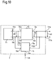
- FIG. 10 illustrates an example of a device which can advantageously be used to produce the source 7 of the generator 1 because it is much less expensive and bulky than a conventional storage battery.
- the source of electrical energy shown schematically and by way of nonlimiting example in FIG. 10, in which it is also designated by the reference 7, comprises a storage battery 71 delivering between its positive terminal 71a and its negative terminal 71b a DC voltage V5 having a value U5 significantly lower than the value U3 of the voltage V3.
- This value U5 of the voltage V5 can be, for example, 12V or 24V.
- This source 7 also includes a voltage booster 72 whose input terminals 72a and 72b are respectively connected to terminals 71a and 71b of the storage battery 71.
- the voltage booster 72 also includes two output terminals 72c and 72d which are connected to the terminals 7.1a and 7.1b of the source 7, which are the terminals designated together by the reference 7.1 in FIG. 1.
- the voltage booster 72 will not be described in detail since it is a circuit well known to specialists. It will simply be mentioned that it is arranged so as to produce between its terminals 72c and 72d, from the voltage V5, a direct voltage having a value at least substantially equal to the value of the voltage V3 when these terminals 72c and 72d do not are connected to no other element.
- This direct voltage which is that which has been designated by the reference V4 in FIG. 1, is of course strictly equal to the voltage V3 when the terminals 72c and 72d are connected to the output terminals of the converter 6 via the terminals 7.1a and 7.1b from source 7.
- the source 7 of FIG. 10 also includes a battery charger 73 whose inputs 73a and 73b are respectively connected to the outputs 72c and 72d of the voltage booster 72 and whose outputs 73c and 73d are respectively connected to the terminals 71a and 71b of the storage battery 71.
- the battery charger 73 will also not be described in detail since it is a well known device. It will simply be mentioned that this battery charger 73 is arranged so as to be able to supply the storage battery 71 with the current necessary for recharging it, at a voltage obviously equal to the voltage V5. For a reason which will be made clear later, the battery charger 73 is further arranged so as to supply the current necessary for recharging the battery. accumulators 71 or to interrupt this current depending on whether a signal SB which it receives on a control input 73e is in a first or a second state.
- the source 7 supplies the consumer device 2 with the electric power which the latter no longer receives when the converter 6 is blocked, totally or partially, that is to say after any increase in the electric power Pe and until the speed of rotation R of the motor 7 has reached its new value.
- the control circuit 4 is arranged so as to provide the battery charger 73 with the signal SB mentioned above and to give this signal SB its first state when the source 7 must be reloaded, that is to say in the circumstances which have just been described, and its second state the rest of the time.
- the signal SB is then in its second state, so that the charger 73 does not supply any current to the storage battery 71.
- the control circuit 4 gives the signal SB its first state, so that the charger 73 begins to recharge the accumulator battery 71, the electric power necessary for this recharging being of course supplied, in mechanical form, by the motor 3 which then supplies its maximum mechanical power as has been described above.
- the control circuit 4 restores the signal SB to its second state , which interrupts the recharging of this storage battery 71, at the same time as it gives the signal SM its value SM2 as has also been described above.
- a rechargeable electrical energy source such as that of FIG. 10 uses a storage battery having only a reduced number of elements to produce the relatively high voltage V3 necessary for the operation of the generator 1. It follows that such a source is significantly less bulky and less expensive than an equivalent device consisting only of a storage battery directly producing the voltage V3, and this even taking into account the size and the price of the voltage booster 72 and charger 73.
- a rechargeable electrical energy source such as that of FIG. 10 can be used in all embodiments of the generator set according to the present invention, and in particular for constitute each of the sources 7a, 7b and 7c of the generator 21 of FIG. 5.
- the engine 3 which will be recalled that it is constituted, in the examples described, by an internal combustion engine powered by a carburetor, can be replaced by any type of fuel engine, provided that understood that the mechanical power supplied by this motor can be adjusted as a function of the value of a signal similar to the SM signal described above.
- Such an engine can be, for example, an engine also with an internal combustion engine but powered by an injection system, or a diesel engine, or a gas turbine, etc.
- the engine 3 can also be constituted, still for example, by a steam or water turbine.
- a generator set such as that which has been described with the aid of FIG. 1 can be modified by replacing the generator 5 with a generator of a type, also well known, such that the voltage V2 is a direct voltage. , and no longer an AC voltage.
- the converter 6 must obviously be arranged so as to produce the constant DC voltage. V3 whatever the value of this voltage V2.
- the measurement circuit 11 producing the signal SR representative of the speed of rotation R of the motor 3 must be adapted accordingly, for example by carrying it out in the manner just mentioned, that is to say using a disc fixed to the shaft connecting the engine 3 to the generator 5, a sensor and an adequate electronic circuit.
- a generator such as that described with the aid of FIG. 9 can obviously be modified in the same way.
- a generator set such as that which has been described with the aid of FIG. 1 can also be modified by adding one or more converters similar to converter 9 to it, and by connecting the inputs of this or these additional converters to the outputs of the converter. 6 and the source 7, the control circuit 4 of this generator set being of course arranged so as to supply the control signals, similar to the SD signal, necessary for the operation of these additional converters.
- a generator set thus modified can therefore supply one or more consumer devices, such as generator 21 in FIG. 5, while being simpler than the latter.
- each of the rechargeable electrical energy sources 7 (FIG. 1), 7a to 7c (FIG. 5) or 7 ′ (FIG. 9) in the form of a set of capacitors, for example electrolytic capacitors.
Abstract
Description
La présente invention a pour objet un groupe électrogène destiné à fournir une énergie électrique sous une première tension, qui est une tension alternative ayant une valeur efficace et une fréquence déterminées, comportant un moteur et un générateur couplé mécaniquement audit moteur pour produire ladite énergie électrique.The subject of the present invention is a generator set intended to supply electrical energy at a first voltage, which is an alternating voltage having a determined effective value and frequency, comprising a motor and a generator mechanically coupled to said motor for producing said electric energy.
Un tel groupe électrogène est évidemment destiné à alimenter en énergie électrique un dispositif consommateur quelconque qui sera simplement appelé "le dispositif consommateur" dans la suite de cette description.Such a generator is obviously intended to supply electrical energy to any consumer device which will be simply called "the consumer device" in the rest of this description.
La tension alternative de sortie d'un groupe électrogène connu, c'est-à-dire la tension qu'il fournit au dispositif consommateur, est directement constituée par la tension produite par le générateur de ce groupe électrogène.The alternating output voltage of a known generator set, that is to say the voltage that it supplies to the consumer device, is directly constituted by the voltage produced by the generator of this generator set.
La fréquence de cette tension de sortie doit bien entendu être aussi constante que possible quelle que soit la puissance électrique qui est absorbée par le dispositif consommateur et que le groupe électrogène doit fournir.The frequency of this output voltage must of course be as constant as possible whatever the electrical power which is absorbed by the consumer device and which the generator set must supply.
Le générateur d'un groupe électrogène connu doit donc, pratiquement, être un générateur de type synchrone, c'est-à-dire un générateur produisant une tension dont la fréquence est proportionnelle à la vitesse de rotation de son rotor, et cette vitesse de rotation doit être réglée à une valeur constante telle que cette fréquence ait la valeur voulue.The generator of a known generator set must therefore, practically, be a synchronous type generator, that is to say a generator producing a voltage whose frequency is proportional to the speed of rotation of its rotor, and this speed of rotation must be set to a constant value such that this frequency has the desired value.
Ce rotor étant couplé mécaniquement à l'arbre de sortie du moteur du groupe électrogène, c'est évidemment la vitesse de rotation de ce moteur qui doit être réglée à une valeur constante.This rotor being mechanically coupled to the output shaft of the generator set engine, it is obviously the rotation speed of this engine which must be adjusted to a constant value.
Ainsi, par exemple, dans un groupe électrogène dont le générateur est bipolaire et si le rotor de ce dernier est directement couplé à l'arbre de sortie du moteur, la vitesse de rotation de ce dernier doit être réglée à 3'000 tours par minute pour que la fréquence de la tension de sortie de ce groupe électrogène soit de 50 Hz, et ceci quelle que soit la puissance électrique absorbée par le dispositif consommateur.Thus, for example, in a generator whose generator is bipolar and if the rotor of the latter is directly coupled to the output shaft of the engine, the the latter's speed of rotation must be adjusted to 3,000 revolutions per minute so that the frequency of the output voltage of this generator set is 50 Hz, regardless of the electrical power absorbed by the consumer device.
Il est bien connu qu'il est difficile de régler avec précision la vitesse de rotation d'un moteur, notamment d'un moteur à combustion interne tel que celui qui est généralement utilisé dans un groupe électrogène, lors de variations rapides de la puissance mécanique qu'il doit fournir.It is well known that it is difficult to precisely regulate the speed of rotation of an engine, in particular of an internal combustion engine such as that which is generally used in a generator, during rapid variations in mechanical power. that he has to provide.
Or, dans un groupe électrogène, cette puissance mécanique dépend évidemment de la puissance électrique absorbée par le dispositif consommateur, qui peut varier en un temps très court entre une valeur faible, voire même nulle, et une valeur élevée, voire même la valeur de la puissance maximale que peut fournir le groupe électrogène, ou inversement.However, in a generator, this mechanical power obviously depends on the electrical power absorbed by the consumer device, which can vary in a very short time between a low value, or even zero, and a high value, even the value of the maximum power that the generator can provide, or vice versa.
Lors de telles variations de cette puissance absorbée par le dispositif consommateur, la vitesse de rotation du moteur d'un groupe électrogène connu, et donc la fréquence de la tension de sortie de ce dernier, ne peuvent donc pratiquement pas être maintenues à la valeur constante désirée.During such variations of this power absorbed by the consumer device, the speed of rotation of the engine of a known generator, and therefore the frequency of the output voltage of the latter, can therefore practically not be maintained at the constant value desired.
Les variations de la fréquence de la tension de sortie d'un groupe électrogène dues à ces variations de vitesse de son moteur peuvent être atténuées, mais non pas complètement éliminées, en disposant un volant d'inertie sur l'arbre qui relie ce moteur au générateur. Mais un tel volant a l'inconvénient d'être un élément lourd et encombrant.The variations in the frequency of the output voltage of a generator set due to these variations in the speed of its engine can be attenuated, but not completely eliminated, by having a flywheel on the shaft which connects this engine to the generator. But such a steering wheel has the disadvantage of being a heavy and bulky element.
La valeur efficace de la tension de sortie d'un groupe électrogène doit également rester constante quelle que soit la puissance électrique absorbée par le dispositif consommateur.The effective value of the output voltage of a generator must also remain constant regardless of the electrical power absorbed by the consumer device.
Pour pouvoir ajuster cette tension de sortie, on utilise généralement dans un groupe électrogène connu un générateur dont le rotor comporte des enroulements dits d'excitation, et on prévoit un circuit adéquat pour modifier le courant passant dans ces enroulements d'excitation en fonction de la puissance électrique absorbée par le dispositif consommateur.To be able to adjust this output voltage, a generator is generally used in a known generator, the rotor of which comprises so-called excitation windings, and an adequate circuit is provided for modifying the current flowing in these excitation windings as a function of the electrical power absorbed by the consumer device.
Mais lors d'un changement rapide de cette puissance électrique, le courant passant dans les enroulements d'excitation ne varie que relativement lentement à cause, notamment, de l'inductivité de ces enroulements, ce qui provoque une variation de la valeur de la tension fournie par le générateur, et donc de la tension de sortie du groupe électrogène.But during a rapid change of this electrical power, the current passing through the excitation windings varies only relatively slowly due, in particular, to the inductivity of these windings, which causes a variation in the value of the voltage. supplied by the generator, and therefore of the generator set output voltage.
La tension fournie par le générateur dépendant en outre de la vitesse de rotation du rotor de ce dernier, la variation de cette tension lors d'un changement de la puissance absorbée par le dispositif utilisateur est encore aggravée par la variation de cette vitesse de rotation qui se produit à ce moment comme cela a été mentionné ci-dessus.The voltage supplied by the generator also depends on the speed of rotation of the rotor of the latter, the variation of this voltage when the power absorbed by the user device changes is further aggravated by the variation of this speed of rotation which occurs at this time as mentioned above.
En résumé, on voit que ni la valeur ni la fréquence de la tension fournie par un groupe électrogène connu ne restent constantes lors d'un changement de la puissance électrique absorbée par le dispositif consommateur qu'il alimente.In summary, it can be seen that neither the value nor the frequency of the voltage supplied by a known generator set remains constant during a change in the electrical power absorbed by the consumer device which it supplies.
Un but de la présente invention est donc de proposer un groupe électrogène qui ne présente pas ces inconvénients, c'est-à-dire un groupe électrogène fournissant une tension alternative ayant une valeur efficace et une fréquence constantes même lors de variations importantes et/ou rapides de la puissance électrique absorbée par le dispositif consommateur qu'il alimente.An object of the present invention is therefore to propose a generator which does not have these drawbacks, that is to say a generator providing an alternating voltage having an effective value and a constant frequency even during large variations and / or of the electrical power absorbed by the consumer device it supplies.
Ce but est atteint par le groupe électrogène revendiqué, qui est destiné à fournir une énergie électrique sous une première tension, qui est une tension alternative ayant une valeur efficace et une fréquence déterminées, comportant un moteur et un générateur couplé mécaniquement audit moteur pour produire ladite énergie électrique, et qui est caractérisé par le fait que ledit générateur est agencé de manière à produire ladite énergie électrique sous une deuxième tension, et qu'il comporte un premier convertisseur couplé électriquement audit générateur pour convertir ladite deuxième tension en une troisième tension, qui est une tension continue ayant une valeur constante, une source d'énergie électrique rechargeable couplée en parallèle avec ledit premier convertisseur, et un deuxième convertisseur couplé électriquement audit premier convertisseur et à ladite source d'énergie électrique rechargeable pour produire ladite première tension à partir de ladite troisième tension.This object is achieved by the claimed generator, which is intended to supply energy electric at a first voltage, which is an alternating voltage having a determined effective value and frequency, comprising a motor and a generator mechanically coupled to said motor to produce said electric energy, and which is characterized in that said generator is arranged so producing said electrical energy under a second voltage, and that it comprises a first converter electrically coupled to said generator for converting said second voltage into a third voltage, which is a direct voltage having a constant value, a source of coupled rechargeable electrical energy in parallel with said first converter, and a second converter electrically coupled to said first converter and to said rechargeable electric power source to produce said first voltage from said third voltage.
D'autres buts et avantages de la présente invention seront rendus évidents par la description qui va être faite ci-après à l'aide du dessin annexé dans lequel :
- la figure 1 représente schématiquement et à titre d'exemple non limitatif une forme d'exécution du groupe électrogène selon l'invention;
- la figure 2 est un diagramme représentant la puissance mécanique fournie par un moteur en fonction de sa vitesse de rotation;
- la figure 3 est un tableau résumant le fonctionnement d'un circuit du groupe électrogène de la figure 1;
- la figure 4 représente la variation en fonction du temps de quelques signaux mesurés dans le groupe électrogène de la figure 1;
- la figure 5 représente schématiquement et également à titre d'exemple non limitatif une autre forme d'exécution du groupe électrogène selon l'invention;
- les figures 6, 7 et 8 représentent schématiquement diverses possibilités d'utilisation du groupe électrogène de la figure 5;
- la figure 9 représente schématiquement et toujours à titre d'exemple non limitatif une autre forme d'exécution du groupe électrogène selon la présente invention; et
- la figure 10 représente schématiquement une source d'énergie électrique rechargeable utilisable dans un groupe électrogène selon l'invention.
- Figure 1 shows schematically and by way of nonlimiting example an embodiment of the generator set according to the invention;
- FIG. 2 is a diagram representing the mechanical power supplied by a motor as a function of its speed of rotation;
- Figure 3 is a table summarizing the operation of a circuit of the generator of Figure 1;
- FIG. 4 represents the variation as a function of time of some signals measured in the generator of FIG. 1;
- Figure 5 shows schematically and also by way of nonlimiting example another embodiment of the generator set according to the invention;
- Figures 6, 7 and 8 schematically show various possibilities of use of the generator of Figure 5;
- Figure 9 shows schematically and still by way of nonlimiting example another embodiment of the generator set according to the present invention; and
- FIG. 10 schematically represents a rechargeable electrical energy source usable in a generator set according to the invention.
Le groupe électrogène selon la présente invention représenté schématiquement et à titre d'exemple non limitatif à la figure 1 avec la référence générale 1 est destiné à produire de l'énergie électrique sous la forme d'une tension alternative V1 ayant une valeur efficace U1 et une fréquence f1.The generator set according to the present invention shown diagrammatically and by way of nonlimiting example in FIG. 1 with the
Cette énergie électrique est destinée à alimenter un dispositif consommateur quelconque représenté de manière très schématique à la figure 1 avec la référence 2.This electrical energy is intended to supply any consumer device shown very schematically in FIG. 1 with the
Comme cela sera rendu évident par la suite de cette description, la tension alternative V1 peut être, selon la manière dont le groupe électrogène 1 est réalisé, une tension monophasée ou polyphasée, par exemple triphasée.As will be made clear later on in this description, the alternating voltage V1 can be, depending on the way in which the
Les bornes de sortie du groupe électrogène 1, dont le nombre dépend évidemment du nombre de phases de la tension V1 et auxquelles les bornes du dispositif consommateur 2 sont reliées, n'ont pas été représentées séparément et sont désignées, ensemble, par la référence S.The output terminals of the
Le groupe électrogène 1 comporte un moteur 3 qui est, dans cet exemple, un moteur à explosion alimenté par un carburateur non représenté séparément.The
La position du papillon de ce carburateur, qui détermine le débit et la composition du mélange de combustible et d'air alimentant le moteur 3 et donc la puissance mécanique fournie par ce dernier pour chacune de ses vitesses de rotation, est commandée par la valeur d'un signal électrique de réglage SM fourni, d'une manière qui sera décrite plus loin, par un circuit de commande 4.The position of the throttle valve of this carburetor, which determines the flow rate and the composition of the mixture of fuel and air supplying the
Le circuit de commande 4 ne sera pas décrit en détail car il peut être réalisé sans difficulté de plusieurs manières différentes par un spécialiste connaissant les diverses fonctions qu'il doit exécuter et qui seront mentionnées plus loin. L'homme du métier verra d'ailleurs facilement que ce circuit de commande 4 peut être réalisé avantageusement, par exemple, en combinant un micro-ordinateur avec des circuits d'interface adéquats et en programmant ce micro-ordinateur de manière qu'il exécute les fonctions voulues.The
Le groupe électrogène 1 comporte en outre un générateur d'énergie électrique 5 ayant de manière classique un stator et un rotor non représentés séparément. Le rotor de ce générateur 5 est directement relié à l'arbre de sortie du moteur 3 par une liaison mécanique symbolisée par un double trait.The
Le générateur 5 peut être de l'un quelconque des divers types de générateurs bien connus qui produisent de l'énergie électrique sous la forme d'une tension alternative, monophasée ou polyphasée, en réponse à une rotation de leur rotor par rapport à leur stator, et ne sera donc pas décrit plus en détail.The
La tension alternative produite par le générateur 5 est désignée dans la figure 1 par la référence V2, et sa valeur efficace et sa fréquence seront respectivement désignées par les références U2 et f2.The alternating voltage produced by the
Comme cela sera rendu évident par la suite de cette description, le nombre de phases de la tension V2 peut très bien être différent de celui de la tension V1. En outre, la valeur efficace U2 et la fréquence f2 de cette tension V2 sont variables et, en général, différentes de la valeur efficace U1 et de la fréquence f1 de la tension V1.As will be made clear later on in this description, the number of phases of the voltage V2 may very well be different from that of the voltage V1. In addition, the effective value U2 and the frequency f2 of this voltage V2 are variable and, in general, different from the effective value U1 and the frequency f1 of the voltage V1.
Les bornes de sortie du générateur 5 entre lesquelles apparaît la tension V2 et dont le nombre dépend évidemment du nombre de phases de cette dernière n'ont pas été représentées séparément et sont désignées, ensemble, par la référence 5.1.The output terminals of the
Le groupe électrogène 1 comporte également un premier circuit convertisseur 6 comportant des premières bornes en nombre égal au nombre des bornes 5.1 du générateur 5 et reliées, chacune, à l'une de ces dernières. Ces premières bornes du convertisseur 6 n'ont pas non plus été représentées séparément et sont désignées, ensemble, par la référence 6.1.The
Le convertisseur 6 comporte en outre des deuxièmes bornes, au nombre de deux, qui n'ont pas non plus été représentées séparément et qui sont désignées par la référence 6.2.The
Il faut noter ici que chacune des diverses liaisons électriques entre les éléments du groupe électrogène 1 décrits ci-dessus ou qui seront décrits plus loin n'est symbolisée dans la figure 1 que par un seul trait, même si cette liaison est constituée par plusieurs fils conducteurs comme cela est évidemment le cas, par exemple, pour la liaison entre le générateur 5 et le convertisseur 6.It should be noted here that each of the various electrical connections between the elements of the
Pour faciliter la compréhension de cette figure 1, les liaisons dont on verra plus loin qu'elles servent à un transfert d'énergie électrique ont été symbolisées par des traits plus épais que celles dont on verra également plus loin qu'elles servent à la transmission de signaux de commande, de réglage ou de mesure.To facilitate the understanding of this figure 1, the connections which we will see later that they are used for a transfer of electrical energy have been symbolized by thicker lines than those which we will also see further that they are used for transmission control, adjustment or measurement signals.
Le convertisseur 6 mentionné ci-dessus est agencé de manière à produire une tension continue V3 entre ses bornes 6.2 en réponse à la tension alternative V2 qu'il reçoit du générateur 5 lorsque ce dernier est entraîné par le moteur 3. Ce convertisseur 6 est en outre agencé de manière que la valeur U3 de cette tension V3 soit constante quelle que soit la valeur efficace de la tension V2 qui, comme on le verra plus loin, peut varier fortement. De plus, ce convertisseur 6 est agencé de manière à régler la puissance électrique qu'il fournit aux éléments qui lui sont raccordés et qui seront décrits plus loin en fonction de la valeur d'un signal de réglage SC qu'il reçoit du circuit de commande 4.The
Dans le présent exemple, et pour une raison qui sera rendue évidente plus loin, le signal SC peut prendre deux valeurs distinctes SC0 et SC1 dans des circonstances qui seront décrites également plus loin. En outre, le convertisseur 6 est agencé de manière à ne transmettre à ses sorties 6.2 aucune puissance électrique lorsque le signal SC a sa valeur SC0, et à transmettre à ces sorties 6.2 toute la puissance électrique qu'il reçoit du générateur 5 lorsque le signal SC a sa valeur SC1.In the present example, and for a reason which will be made clear later, the signal SC can take two distinct values SC0 and SC1 under circumstances which will be described also below. In addition, the
Un convertisseur tel que le convertisseur 6 est un circuit bien connu des spécialistes et ne sera donc pas décrit en détail.A converter such as the
On rappellera simplement qu'un tel convertisseur comporte généralement un stabilisateur de tension produisant la tension continue désirée à partir d'une tension redressée et éventuellement filtrée fournie par un redresseur recevant la tension alternative appliquée au convertisseur, et ceci même si la valeur de crête de la tension redressée est inférieure à la valeur que doit avoir la tension continue.It will simply be recalled that such a converter generally comprises a voltage stabilizer producing the desired DC voltage from a rectified and possibly filtered voltage supplied by a rectifier receiving the alternating voltage applied to the converter, and this even if the peak value of the rectified voltage is less than the value that must have the DC voltage.
Le groupe électrogène 1 comporte encore une source d'énergie électrique rechargeable, désignée par la référence 7, c'est-à-dire un dispositif capable d'emmagasiner et de restituer une certaine quantité d'énergie électrique sous une tension continue. La source 7 comporte deux bornes, désignées ensemble par la référence 7.1, qui sont reliées, chacune, à l'une des bornes de sortie 6.2 du convertisseur 6. La source 7 est en outre agencée de manière que la tension V4 qu'elle produit entre ses bornes 7.1 lorsque ces dernières ne sont pas reliées aux bornes 6.2 du convertisseur 6 soit au moins sensiblement égale à la tension V3 produite par ce dernier.The
Lorsque les bornes 7.1 de la source 7 et les bornes 6.2 du convertisseur 6 sont reliées, les tensions V3 et V4 sont évidemment strictement égales.When the terminals 7.1 of the
On admettra que, dans le présent exemple, la source 7 est constituée par une batterie d'accumulateurs classiques tels que des accumulateurs au plomb ou au cadmium-nickel. On notera cependant que la source 7 peut également être constituée d'une manière différente dont un exemple sera décrit plus loin.It will be assumed that, in the present example, the
Le groupe électrogène 1 comporte également un circuit de surveillance 8 relié à la source 7 et agencé de manière à fournir au circuit de commande 4 un signal de mesure SQ représentatif de l'état de charge de cette source 7, c'est-à-dire de la quantité d'énergie électrique disponible dans cette dernière. On admettra que, dans le présent exemple, le signal SQ a une valeur maximale SQ1 lorsque la source 7 est complètement chargée, et diminue en même temps que cette source 7 se décharge.The
Le circuit de surveillance 8 et ses liaisons avec la source 7 ne seront pas décrits en détail car ils peuvent être réalisés de diverses manières bien connues des spécialistes. On mentionnera simplement ici qu'un tel circuit de surveillance comporte généralement au moins deux circuits fournissant des signaux de mesure respectivement représentatifs de la tension aux bornes de la source à laquelle il est associé et du courant de charge ou de décharge de cette dernière, et éventuellement des circuits fournissant des signaux de mesure représentatifs d'autres paramètres de la source tels que sa température ou son age, c'est-à-dire le temps qui s'est écoulé depuis sa première mise en service. Un tel circuit de surveillance comporte également, bien entendu, un circuit de calcul capable d'élaborer le signal représentatif de l'état de la source à laquelle il est relié en fonction des différents signaux de mesure mentionnés ci-dessus.The
Le groupe électrogène 1 comporte encore un deuxième circuit convertisseur, désigné par la référence 9.The
Ce convertisseur 9 comporte deux bornes d'entrée désignées ensemble par la référence 9.1 et reliées, chacune, à l'une des bornes 6.2 du convertisseur 6, ainsi que des bornes de sortie désignées ensemble par la référence 9.2. Ces bornes de sortie 9.2 sont en nombre égal au nombre des bornes de sortie S du groupe électrogène 1 et sont reliées, chacune, à l'une de ces dernières par l'intermédiaire d'un circuit de mesure 10 qui sera décrit plus loin.This
Le convertisseur 9 est destiné à produire la tension alternative V1 de sortie du groupe électrogène 1 à partir de la tension continue V3. Ce convertisseur 9 est donc un circuit du même genre que les circuits couramment appelés onduleurs, qui sont bien connus et ne seront donc pas décrits en détail ici.The
On rappellera simplement qu'un onduleur est un circuit qui est destiné à produire une tension alternative, qui peut être monophasée ou multiphasée, à partir d'une tension continue, la valeur de crête de cette tension alternative étant au plus égale à la valeur de cette tension continue. Dans ce but, un onduleur comporte notamment des éléments électroniques tels que des transistors ou des thyristors dont le nombre et le branchement dépendent de la nature monophasée ou polyphasée de la tension alternative qu'il doit produire. En outre, chacun de ces éléments électroniques est commandé par un signal formé d'impulsions périodiques dont la largeur varie en suivant une fonction sinusoïdale. Les diverses fonctions sinusoïdales définissant ces largeurs d'impulsions ont toutes la même amplitude et la même fréquence, qui déterminent respectivement la valeur efficace et la fréquence de la tension alternative produite par l'onduleur, mais sont déphasées les unes par rapport aux autres d'une quantité qui dépend également de la nature monophasée ou multiphasée de cette tension alternative.It will simply be recalled that an inverter is a circuit which is intended to produce an alternating voltage, which can be single-phase or multi-phase, from a direct voltage, the peak value of this alternating voltage being at most equal to the value of this tension continues. For this purpose, an inverter includes in particular electronic elements such as transistors or thyristors, the number and connection of which depend on the single-phase or polyphase nature of the alternating voltage which it must produce. In addition, each of these electronic elements is controlled by a signal formed by periodic pulses whose width varies according to a sinusoidal function. The various sinusoidal functions defining these pulse widths all have the same amplitude and the same frequency, which respectively determine the rms value and the frequency of the alternating voltage produced by the inverter, but are out of phase with each other by an amount which also depends on the single-phase or multiphase nature of this alternating voltage.
Dans le groupe électrogène 1, les divers signaux de commande des éléments électroniques de l'onduleur constituant le convertisseur 9 sont produits en permanence par le circuit de commande 4 et ce convertisseur 9 fonctionne donc également en permanence. Pour ne pas charger inutilement le dessin, l'ensemble des liaisons par lesquelles ces signaux de commande sont transmis du circuit de commande 4 au convertisseur 9 n'a été représenté que par une seule ligne. En outre, pour ne pas compliquer inutilement la description qui va suivre, l'ensemble de ces signaux de commande sera simplement appelé signal de commande du convertisseur 9 et sera désigné par la référence SD.In the
Le groupe électrogène 1 comporte encore deux circuits de mesure désignés respectivement par les références 10 et 11.The
Le circuit de mesure 10 est disposé entre les bornes de sortie 9.2 du convertisseur 9 et les bornes de sortie S du groupe électrogène 1, et il est agencé de manière à fournir au circuit de commande 4 un signal de mesure SP représentatif de la puissance électrique fournie par le groupe électrogène 1 au dispositif consommateur 2, qui est évidemment identique à la puissance électrique absorbée par ce dernier. Ces deux puissances étant identiques, elles seront toutes deux désignées par la même référence Pe dans la suite de cette description.The
Le circuit de mesure 10 est en outre agencé de manière que la tension V1 fournie par le convertisseur 9 soit appliquée sans modification aux bornes de sortie S du groupe électrogène 1.The
Ce circuit de mesure 10 ne sera pas décrit en détail car il peut être réalisé de diverses manières bien connues des spécialistes. On mentionnera simplement ici que ce circuit 10 peut comporter deux circuits fournissant des signaux de mesure respectivement représentatifs de la valeur efficace de la tension V1 et du courant absorbé par le dispositif consommateur 2, ainsi que le circuit de calcul nécessaire à l'élaboration du signal SP en réponse à ces signaux de mesure.This
Le circuit de mesure 11 comporte des bornes d'entrée reliées, dans cet exemple, aux bornes 5.1 du générateur 5, et il est agencé de manière à fournir au circuit de commande 4 un signal de mesure SR représentatif de la vitesse de rotation du rotor de ce générateur 5 et donc de la vitesse de rotation du moteur 3. Cette vitesse de rotation sera désignée par la référence R dans la suite de cette description.The
Le circuit de mesure 11 ne sera pas non plus décrit en détail car il peut être réalisé de diverses manières bien connues des spécialistes. On admettra que, dans le présent exemple, ce circuit 11 est agencé de manière que le signal SR dépende de la fréquence f2 de la tension V2, fréquence qui est bien entendu proportionnelle à la vitesse de rotation R du rotor du générateur 5 et du moteur 3.The
Il faut noter que, si cela est nécessaire, des moyens de protection contre toute surintensité constitués par exemple par des fusibles ou des disjoncteurs peuvent être intercalés entre le circuit de mesure 10 et les bornes de sortie S du groupe électrogène 1. De tels moyens de protection n'ont pas été représentés car ils n'ont pas de lien direct avec la présente invention.It should be noted that, if necessary, means of protection against any overcurrent constituted for example by fuses or circuit breakers can be interposed between the
Comme cela sera décrit en détail plus loin, la puissance électrique Pe absorbée par le dispositif consommateur 2 lorsque le groupe électrogène 1 fonctionne est généralement fournie, sous forme de puissance mécanique, par le moteur 3. Cette puissance mécanique, qui sera désignée par Pm, est transformée en puissance électrique par le générateur 5 et transmise au dispositif consommateur 2 par l'intermédiaire des convertisseurs 6 et 9.As will be described in detail below, the electrical power Pe absorbed by the
Une partie de la puissance mécanique Pm fournie par le moteur 3 est dissipée dans le générateur 5 lors de sa transformation en puissance électrique, et une partie de cette dernière est dissipée dans les convertisseurs 6 et 9 lors de sa transmission au dispositif consommateur 2.Part of the mechanical power Pm supplied by the
La puissance dissipée dans le générateur 5 et dans les convertisseurs 6 et 9 est cependant généralement faible par rapport à la puissance électrique Pe fournie par le groupe électrogène 1 et sera négligée dans la description détaillée du fonctionnement de ce groupe électrogène 1 qui va suivre, car l'homme du métier verra sans difficulté comment dimensionner les divers composants du groupe électrogène 1 pour tenir compte, si nécessaire, de cette puissance dissipée.The power dissipated in the
La figure 2 représente schématiquement la variation bien connue de la puissance mécanique Pm fournie par le moteur 3 en fonction de sa vitesse de rotation R pour trois valeurs différentes SM0, SM1 et SM2 du signal SM. Dans le présent exemple, la valeur SM0 est celle pour laquelle le papillon du carburateur du moteur 3 est complètement fermé ou, en d'autres termes, occupe la position généralement appelée position de ralenti. Lorsque le signal SM a cette valeur SM0, le moteur 3 ne fournit donc presque plus de puissance mécanique, quelle que soit sa vitesse de rotation. De même, la valeur SM1 est celle pour laquelle le papillon du carburateur du moteur 3 est complètement ouvert, c'est-à-dire pour laquelle ce moteur 3 fournit, à chacune de ses vitesses de rotation, la puissance maximale qu'il peut fournir à cette vitesse. Enfin, la valeur SM2 est celle pour laquelle ce papillon occupe une position telle que le moteur 3 fournit, à chacune de ses vitesses de rotation, une fraction déterminée de la puissance maximale qu'il peut fournir à cette vitesse. On admettra que cette fraction déterminée est égale à 80% dans le présent exemple.FIG. 2 schematically represents the well-known variation of the mechanical power Pm supplied by the
Pour une raison qui sera rendue évidente plus loin, les circuits de mesure 10 et 11 mentionnés ci-dessus sont agencés de manière que les signaux SP et SR soient de même nature. Par exemple, chacun de ces signaux SP et SR peut être constitué par une tension électrique. En outre, ces circuits de mesure 10 et 11 sont agencés de manière que, quelle que soit la puissance électrique Pe absorbée par le dispositif consommateur 2, les signaux SP et SR soient égaux lorsque le signal SM a la valeur SM2 définie ci-dessus et que le moteur 3 tourne à la vitesse à laquelle la puissance mécanique Pm qu'il fournit est égale à cette puissance électrique Pe.For a reason which will be made clear later, the above-mentioned
De plus, le circuit de commande 4 est agencé de manière que le signal SM ait la valeur SM0 lorsque le signal SP est inférieur au signal SR et la valeur SM1 lorsque ce signal SP est supérieur au signal SR, et de manière que, lorsque ces signaux SP et SR sont égaux, ce signal SM ait la valeur SM2 si le signal SQ est égal à SQ1 et la valeur SM1 si ce signal SQ est inférieur à SQ1. Ce circuit de commande 4 est en outre agencé de manière que le signal SC ait sa valeur SC1 lorsque le signal SP est inférieur ou égal au signal SR et sa valeur SC0 lorsque ce signal SP est supérieur à ce signal SR.In addition, the
Ce fonctionnement du circuit de commande 4 est résumé dans le tableau de la figure 3.This operation of the
Le fonctionnement du groupe électrogène 1 va être décrit ci-après, en commençant à un instant arbitraire où la puissance électrique Pe absorbée par le dispositif consommateur 2 a une valeur Pe1 non nulle, inférieure à la puissance électrique maximale que peut fournir le groupe électrogène 1 et n'ayant pas varié depuis un certain temps. On admettra en outre que, à ce même instant, la source 7 est complètement chargée et que le signal SQ a donc sa valeur SQ1.The operation of
Dans ces conditions, et comme cela sera rendu évident plus loin, le moteur 3 tourne à la vitesse R1 pour laquelle le signal SR a une valeur SR1 égale à la valeur SP1 du signal SP correspondant à la valeur Pe1 de la puissance électrique Pe.Under these conditions, and as will be made clear later, the
Le signal SM a donc la valeur SM2, et le moteur 3 fournit une puissance Pm1 égale, d'une part, à cette puissance électrique Pe1 et, d'autre part, à 80% de la puissance mécanique maximale Pm1' qu'il peut fournir à cette vitesse R1.The signal SM therefore has the value SM2, and the
La puissance électrique produite par le générateur 5 a donc également la valeur Pe1.The electric power produced by the
En outre, le signal SC a la valeur SC1, de sorte que le convertisseur 6 transmet au convertisseur 9 toute la puissance électrique Pe1 qu'il reçoit du générateur 5. Le convertisseur 9 fonctionnant en permanence, cette puissance électrique Pe1 est donc transmise en totalité au dispositif utilisateur 2.In addition, the signal SC has the value SC1, so that the
Il faut noter que, dans cette situation, la vitesse de rotation R du moteur 3 ne varie pas puisque la puissance mécanique Pm1 qu'il produit est égale à celle qui est absorbée par le générateur 5 pour produire la puissance électrique Pe1, et que le couple moteur fourni par ce moteur 3 est donc égal au couple de freinage créé par ce générateur 5.It should be noted that, in this situation, the speed of rotation R of the
Le groupe électrogène 1 est donc dans une situation stable qui reste inchangée tant que la puissance électrique Pe absorbée par le dispositif consommateur 2 reste constante.The
Considérons maintenant un cas où, après être restée un certain temps à la valeur Pe1, la puissance électrique Pe absorbée par le dispositif consommateur 2 diminue brusquement et prend une nouvelle valeur non nulle Pe2.Let us now consider a case where, after having remained at the value Pe1 for a certain time, the electrical power Pe absorbed by the
Le signal SP prend alors une nouvelle valeur SP2 inférieure à la valeur SP1 précédente. Le circuit de commande 4 donne donc au signal SM la valeur SM0 pour laquelle le papillon du carburateur du moteur 3 est dans sa position de ralenti, mais continue à donner au signal SC la valeur SC1.The signal SP then takes a new value SP2 lower than the previous value SP1. The
Le moteur 3 ne fournit donc pratiquement plus de puissance mécanique mais continue à tourner, à une vitesse décroissante, en réponse à son énergie cinétique et à celle du générateur 5. Ce dernier continue donc à fournir de la puissance électrique, et comme le signal SC a sa valeur SC1, cette puissance électrique est égale à la puissance électrique Pe2 qui est absorbée par le dispositif consommateur 2.The
Lorsque la vitesse de rotation R du moteur 3 atteint la valeur R2 pour laquelle la valeur SR2 du signal SR est égale à la nouvelle valeur SP2 du signal SP, le circuit de commande 4 redonne au signal SM la valeur SM2.When the speed of rotation R of the
La puissance mécanique Pm2 que le moteur 3 fournit alors est donc à nouveau égale au 80% de sa puissance mécanique maximale Pm2', et cette puissance mécanique Pm2 est en outre égale à la puissance électrique Pe2 absorbée par le dispositif consommateur 2 puisque la valeur SR2 du signal SR est égale à la valeur SP2 du signal SP.The mechanical power Pm2 that the
Le groupe électrogène 1 se trouve donc à nouveau dans une situation stable qui ne diffère de la précédente que par les valeurs de la vitesse de rotation R du moteur 3, de la puissance mécanique Pm qu'il fournit, et de la puissance électrique Pe produite par le générateur 5 et transmise au dispositif utilisateur 2 par l'intermédiaire des convertisseurs 6 et 9.The
Cette situation reste inchangée tant que la valeur de cette puissance électrique Pe reste constante et égale à Pe2.This situation remains unchanged as long as the value of this electrical power Pe remains constant and equal to Pe2.
Considérons maintenant un cas où, après être restée un certain temps à la valeur Pe2, la puissance électrique Pe absorbée par le dispositif consommateur 2 augmente brusquement et prend une nouvelle valeur Pe3.Let us now consider a case where, after having remained for a certain time at the value Pe2, the electric power Pe absorbed by the
Le signal SP prend alors une nouvelle valeur SP3 supérieure à la valeur SP2 précédente. Le circuit de commande 4 donne donc au signal SM la valeur SM1 pour laquelle le papillon du carburateur du moteur 3 est complètement ouvert.The signal SP then takes a new value SP3 greater than the previous value SP2. The
Simultanément, le circuit de commande 4 donne au signal SC sa valeur SC0 pour laquelle le convertisseur 6 ne fournit plus aucune puissance électrique.Simultaneously, the
La puissance électrique fournie par le générateur 5 devient donc également nulle, de même que le couple de freinage exercé par ce générateur 5 sur le moteur 3. Toute la puissance mécanique fournie par le moteur 3 est donc maintenant disponible pour accélérer ce dernier et le rotor du générateur 5.The electric power supplied by the
Le convertisseur 6 ne fournissant plus de puissance électrique, la puissance électrique Pe3 absorbée par le dispositif consommateur 2 est maintenant fournie par la source 7. Cette dernière se décharge donc, et la valeur du signal SQ diminue et devient inférieure à SQ1.The
Lorsque la vitesse de rotation R du moteur 3 atteint la valeur R3 pour laquelle la valeur SR3 du signal SR est égale à la valeur SP3 du signal SP, le circuit de commande 4 redonne au signal SC sa valeur SC1, mais maintient encore le signal SM à sa valeur maximale SM1, puisque le signal SQ est inférieur à SQ1.When the speed of rotation R of the
Dans ces conditions, le moteur 3 fournit sa puissance mécanique maximale Pm3', et le générateur 5 fournit une puissance électrique égale à cette puissance mécanique Pm3' et supérieure à la valeur Pe3 de la puissance électrique Pe absorbée par le dispositif consommateur 2.Under these conditions, the
La différence entre cette puissance Pm3', qui est également celle qui est fournie par le convertisseur 6 puisque le signal SC a sa valeur SC1, et la puissance Pe3 absorbée par le dispositif consommateur 2 est absorbée par la source 7, dont on rappellera qu'elle est constituée dans le présent exemple par une batterie d'accumulateurs classiques, qui est partiellement déchargée à cet instant comme cela a été mentionné ci-dessus.The difference between this power Pm3 ', which is also that which is supplied by the
Les bornes 7.1 de la source 7 étant directement reliées aux bornes de sortie 6.2 du convertisseur 6, cette source 7 se recharge donc sous une tension constante, c'est-à-dire la tension V3, et le courant qu'elle absorbe pendant sa charge diminue au fur et à mesure que la quantité d'énergie électrique qu'elle contient augmente.The terminals 7.1 of the
Cette diminution du courant absorbé par la source 7 a pour effet que la puissance mécanique que doit fournir le moteur 3 diminue et que sa vitesse de rotation R a tendance à augmenter, de même que la valeur du signal SR.This reduction in the current absorbed by the
Mais dès que la valeur de ce signal SR devient supérieure à la valeur SP3 du signal SP, le circuit de commande 4 redonne au signal SM la valeur SM0, de sorte que la puissance mécanique Pm fournie par le moteur 3 devient presque nulle et que sa vitesse de rotation R diminue. Lorsque la valeur du signal SR atteint à nouveau la valeur SR3 égale à la valeur SP3, le circuit de commande 4 redonne au signal SM la valeur SM1 et le moteur 3 recommence à fournir sa puissance maximale Pm3'.But as soon as the value of this signal SR becomes greater than the value SP3 of the signal SP, the
Ce processus se répète plusieurs fois mais, comme le courant absorbé par la source 7 continue à diminuer, le rapport entre le temps pendant lequel le moteur 3 fournit sa puissance maximale Pm3' et le temps pendant lequel il ne fournit qu'une puissance presque nulle diminue, de sorte que la puissance mécanique moyenne fournie par ce moteur 3 diminue progressivement.This process is repeated several times but, as the current absorbed by the
Lorsque la source 7 est complètement rechargée, le signal SQ atteint à nouveau la valeur SQ1. Le circuit de commande 4 redonne alors la valeur SM2 au signal SM lorsque le moteur 3 tourne à la vitesse R3 et que le signal SR a donc sa valeur SR3 égale à la valeur SP3 du signal SP.When the
La puissance mécanique Pm3 que le moteur 3 fournit alors est donc à nouveau égale au 80% de sa puissance mécanique maximale Pm3', et cette puissance mécanique Pm3 est en outre égale à la puissance électrique Pe3 absorbée par le dispositif consommateur 2 puisque la valeur SR3 du signal SR est égale à la valeur SP3 du signal SP.The mechanical power Pm3 that the
Cette situation reste inchangée tant que la puissance électrique Pe absorbée par le dispositif consommateur 2 ne varie pas et reste égale à Pe3.This situation remains unchanged as long as the electrical power Pe absorbed by the
Un processus similaire à l'un de ceux qui viennent d'être décrits se déroule évidemment chaque fois que la puissance électrique Pe absorbée par le dispositif consommateur 2 se modifie.A process similar to one of those which have just been described obviously takes place each time the electrical power Pe absorbed by the
La figure 4 illustre schématiquement le déroulement des divers processus décrits ci-dessus en fonction du temps t.Figure 4 schematically illustrates the progress of the various processes described above as a function of time t.
Dans cette figure 4, le diagramme a) représente par un trait continu la puissance électrique Pe absorbée par le dispositif consommateur 2 et le signal SP correspondant ainsi que, par un trait interrompu, le signal SR représentatif de la vitesse de rotation R du moteur 3. Comme on l'a vu ci-dessus, le signal SR n'est différent du signal SP que pendant de courts laps de temps qui suivent chaque changement de la valeur de la puissance électrique Pe. C'est pourquoi le trait interrompu représentant le signal SR n'est visible qu'aux endroits du diagramme a) correspondant à ces laps de temps.In this FIG. 4, the diagram a) represents by a solid line the electrical power Pe absorbed by the
Les diagrammes b) à e) de cette figure 4 représentent respectivement les valeurs du signal SM, de la puissance mécanique Pm fournie par le moteur 3, du signal SC et du signal SQ.Diagrams b) to e) of this FIG. 4 respectively represent the values of the signal SM, of the mechanical power Pm supplied by the
Il faut noter que les variations du signal SR et de la puissance mécanique Pm ne sont généralement pas linéaires comme cela a été représenté dans un but de simplification.It should be noted that the variations of the signal SR and of the mechanical power Pm are generally not linear as has been shown for the purpose of simplification.
Les divers éléments du groupe électrogène 1, et notamment le circuit de commande 4, peuvent évidemment être agencés de manière que ce groupe électrogène 1 fonctionne d'une manière différente de celle qui vient d'être décrite.The various elements of the
Ainsi, par exemple, le circuit de commande 4 peut être agencé de manière que, lorsque la puissance électrique Pe absorbée par le dispositif consommateur 2 augmente, le signal SC ne prenne pas sa valeur SC0 comme dans l'exemple décrit ci-dessus mais une autre valeur fixe telle que le convertisseur 6 continue à fonctionner, tout en limitant la puissance électrique qu'il transmet de ses entrées 6.1 à ses sorties 6.2 à une valeur non nulle déterminée par cette autre valeur du signal SC. Cette puissance électrique limitée est évidemment produite par le générateur 5, de sorte que la puissance mécanique fournie par le moteur 3 ne sert plus exclusivement à accélérer ce dernier et le rotor du générateur 5, une partie de cette puissance mécanique étant encore convertie en puissance électrique par le générateur 5. Pendant cette accélération, la source 7 ne doit donc fournir que la partie de la puissance électrique Pe absorbée par le dispositif consommateur 2 qui n'est plus fournie par le convertisseur 6.Thus, for example, the
Il est donc possible, dans un tel cas, de dimensionner la source 7 de manière que la quantité maximale d'énergie électrique qu'elle doit pouvoir emmagasiner soit plus faible, et donc que son prix de revient soit plus bas, que dans l'exemple décrit à l'aide de la figure 4.It is therefore possible, in such a case, to size the
Dans un cas similaire à celui qui vient d'être décrit, la valeur donnée au signal SC par le circuit de commande 4 peut ne pas être fixe mais dépendre de la valeur de l'augmentation de la puissance électrique Pe absorbée par le dispositif consommateur 2.In a case similar to that just described, the value given to the signal SC by the
On voit que chaque variation de la puissance électrique Pe absorbée par le dispositif consommateur 2 entraîne une variation de la vitesse de rotation R du moteur 3 et du générateur 5, et donc une variation de la valeur efficace U2 et de la fréquence f2 de la tension alternative V2 produite par ce dernier.It can be seen that each variation in the electrical power Pe absorbed by the
Mais on voit également que ces variations de la valeur efficace U2 et de la fréquence f2 de la tension V2 n'ont aucune influence sur la valeur efficace U1 et sur la fréquence f1 de la tension V1 produite par le groupe électrogène 1 puisque cette valeur efficace U1 et cette fréquence f1 ne dépendent que de la valeur U3 de la tension continue V3, qui est constante, et des caractéristiques du signal SD commandant le convertisseur 9, qui sont déterminées par le circuit de commande 4 indépendamment de la valeur efficace U2 et de la fréquence f2 de la tension V2.But it can also be seen that these variations of the effective value U2 and of the frequency f2 of the voltage V2 have no influence on the effective value U1 and on the frequency f1 of the voltage V1 produced by the
Cette propriété du groupe électrogène 1 constitue un grand avantage de ce dernier par rapport aux groupes électrogènes connus.This property of
On voit de plus que la valeur efficace U1 et la fréquence f1 de la tension V1 peuvent être choisies très librement puisqu'il suffit d'agencer le circuit de commande 4 de manière que le signal SD de commande du convertisseur 9 ait les caractéristiques voulues. On peut même agencer le circuit de commande 4 de manière que ces caractéristiques du signal SD, et donc cette valeur efficace U1 et/ou cette fréquence f1, dépendent, par exemple, de la position d'un ou de plusieurs commutateurs disposés sur un tableau de commande du groupe électrogène 1. Par exemple, dans un cas où la tension V1 est une tension monophasée, on peut prévoir un commutateur à deux positions sur ce tableau de commande et agencer le circuit de commande 4 de manière que la valeur efficace U1 et la fréquence f1 de la tension V1 soient respectivement égales à 220V et à 50 Hz ou à 110V et 60 Hz selon que ce commutateur est dans l'une ou l'autre de ses positions.It can also be seen that the effective value U1 and the frequency f1 of the voltage V1 can be chosen very freely since it suffices to arrange the
En outre, le fait que la valeur efficace U1 de la tension alternative V1 produite par le groupe électrogène 1 est indépendante de la valeur efficace U2 de la tension alternative V2 produite par le générateur 5 évite d'avoir à réguler cette tension V2.In addition, the fact that the effective value U1 of the alternating voltage V1 produced by the
Il en résulte que le groupe électrogène 1 présente l'avantage supplémentaire de ne comporter aucun dispositif semblable à celui qui sert, dans les groupes électrogènes connus, à régler l'intensité du courant passant dans les enroulements d'excitation du rotor du générateur.As a result, the
De plus, le rotor du générateur 5 du groupe électrogène 1 ne doit pas obligatoirement comporter de tels enroulements d'excitation, ceux-ci pouvant avantageusement être remplacés par des aimants permanents. Ceci représente un autre avantage du groupe électrogène 1 par rapport aux groupes électrogènes connus, car on sait qu'un générateur dont le rotor comporte des aimants permanents est généralement moins encombrant et moins cher qu'un générateur dont le rotor comporte des enroulements d'excitation.In addition, the rotor of the
On a vu ci-dessus que, quelle que soit la vitesse de rotation R du moteur 3, celui-ci fournit la plupart du temps une puissance mécanique qui est une fraction définie de sa puissance maximale à cette vitesse. Il est donc possible de dimensionner le moteur 3 de manière que son rendement soit maximal, ou au moins presque maximal, et que la quantité de gaz polluants qu'il émet soit minimale, ou au moins presque minimale, lorsqu'il fournit cette fraction définie de sa puissance maximale.We have seen above that, whatever the speed of rotation R of the
Une telle optimalisation du rendement et de la quantité de gaz polluants émis n'est pas possible pour les moteurs équipant les groupes électrogènes connus, puisque ces moteurs doivent tourner à une vitesse de rotation constante en fournissant une puissance mécanique variable et qu'ils ne fonctionnent donc presque jamais dans des conditions optimales de rendement et d'émission de gaz polluants.Such an optimization of the yield and of the quantity of polluting gases emitted is not possible for the engines equipping the known generator sets, since these engines must turn at a constant speed of rotation while providing a variable mechanical power. and that they therefore hardly ever operate under optimum conditions of yield and emission of polluting gases.
Dans sa forme d'exécution représentée schématiquement à la figure 5, le groupe électrogène selon la présente invention, qui est désigné par la référence 21, comporte un moteur semblable au moteur 3 du groupe électrogène 1 de la figure 1 et désigné par la même référence. Le moteur 3 du groupe électrogène 21 comporte, comme le moteur 3 du groupe électrogène 1, un carburateur ayant un papillon dont la position dépend de la valeur d'un signal, également désigné par SM, produit par un circuit de commande 24.In its embodiment shown diagrammatically in FIG. 5, the generator set according to the present invention, which is designated by the
Le circuit de commande 24 ne sera pas décrit en détail car il peut être réalisé de diverses manières et sans difficulté par un homme du métier connaissant le fonctionnement du groupe électrogène 21.The
En particulier, et comme le circuit de commande 4 de la figure 1, ce circuit de commande 24 peut être réalisé par exemple en combinant un micro-ordinateur avec des circuits d'interface adéquats et en programmant ce micro-ordinateur de manière qu'il exécute les fonctions voulues.In particular, and like the
Le moteur 3 est couplé mécaniquement au rotor, non représenté, d'un générateur 25 dont le stator comporte, dans cet exemple, trois enroulements 25a, 25b et 25c isolés électriquement les uns des autres.The
Le groupe électrogène 21 comporte encore trois ensembles d'éléments formés chacun d'un premier convertisseur 6, d'une source 7, d'un circuit de surveillance 8, d'un deuxième convertisseur 9 et d'un circuit de mesure 10, ces références numériques étant complétées par une lettre a, b ou c selon l'ensemble dont fait partie chaque élément.The
Chacun de ces éléments 6a à 10a, 6b à 10b et 6c à 10c est semblable à l'élément désigné par la même référence numérique dans la figure 1 et, dans chaque ensemble, les éléments sont reliés entre eux comme les éléments correspondants de la figure 1. Ces éléments et leurs liaisons ne seront donc pas décrits à nouveau ici.Each of these
On mentionnera simplement que les entrées des convertisseurs 6a à 6c sont respectivement reliées aux enroulements 25a à 25c du générateur 25. De même, les convertisseurs 9a à 9c sont agencés dans cet exemple de manière que les tensions alternatives V1a, V1b et V1c qu'ils produisent soient des tensions monophasées. Il faut noter que cette caractéristique n'est cependant pas obligatoire et que, dans d'autres formes d'exécution, ces convertisseurs 9a, 9b et 9c peuvent être agencés de manière qu'une ou plusieurs de ces tensions V1a, V1b et V1c soient des tensions polyphasées, par exemple triphasées.It will simply be mentioned that the inputs of the
Par analogie avec le cas de la figure 1, les signaux de commande des convertisseurs 6a à 6c et 9a à 9c, qui sont produits par le circuit de commande 24, ainsi que les signaux fournis à ce circuit de commande 24 par les circuits de surveillance 8a à 8c et par les circuits de mesure 10a à 10c sont également désignés par les références SC, SD, SQ et, respectivement, SP, ces références étant complétées par la même lettre a, b ou c que la référence numérique de l'élément concerné.By analogy with the case of FIG. 1, the control signals of the
Le groupe électrogène 21 comporte encore des bornes de sortie S1a, S2a, S1b, S2b, S1c et S2c qui sont reliées, chacune, à une sortie de l'un des convertisseurs 9a à 9c par l'intermédiaire des circuits de mesure 10a à 10c. Les tensions alternatives produites par ces convertisseurs 9a à 9c, qui sont respectivement désignées par les références V1a, V1b et V1c, apparaissent donc entre les bornes S1a et S2a, S1b et S2b et, respectivement, S1c et S2c.The
Le groupe électrogène 21 comporte également un circuit de mesure de la vitesse de rotation du générateur 25 semblable au circuit 11 de la figure 1 et désigné par la même référence que ce dernier. Ce circuit de mesure 11 est relié à l'enroulement 25a du générateur 25, et il fournit au circuit de commande 24 un signal, également désigné par SR, qui est représentatif de la fréquence de la tension V2a produite par cet enroulement 25a en réponse à la rotation du rotor du générateur 25, et donc représentatif de la vitesse de rotation du moteur 3.The
Le fonctionnement du groupe électrogène 21 ne sera pas décrit en détail car il est très semblable à celui du groupe électrogène 1.The operation of the
Il faut cependant noter que le groupe électrogène 21 peut être utilisé pour alimenter en énergie électrique un ou plusieurs dispositifs consommateurs, comme cela sera montré plus loin, et que dans ce dernier cas, ces dispositifs consommateurs peuvent absorber des puissances électriques différentes les unes des autres.It should however be noted that the
Le circuit de commande 24 est donc agencé de manière que, quelle que soit la puissance électrique totale absorbée par le ou les dispositifs consommateurs, le moteur 3 tourne la plupart du temps à la vitesse pour laquelle la puissance mécanique qu'il fournit, qui est égale à cette puissance électrique totale, soit aussi égale à une fraction déterminée, par exemple 80 %, de sa puissance mécanique maximale à cette vitesse.The
Pour assurer ce réglage, le circuit de commande 24 détermine en permanence la somme des signaux SPa, SPb et SPc, compare cette somme à la valeur du signal SR et détermine en fonction de cette comparaison la valeur des signaux SM, SCa, SCb et SCc d'une manière similaire à celle qui a été décrite ci-dessus dans le cadre de la description du fonctionnement du groupe électrogène 1.To ensure this adjustment, the
Les valeurs efficaces et les fréquences des trois tensions V1a, V1b et V1c sont évidemment indépendantes de la puissance électrique absorbée par le ou les dispositifs consommateurs alimentés par le groupe électrogène 21, pour les mêmes raisons, mentionnées ci-dessus, que dans le cas de la tension V1 produite par le groupe électrogène 1.The effective values and the frequencies of the three voltages V1a, V1b and V1c are obviously independent of the electrical power absorbed by the consumer device (s) supplied by the
Ces trois tensions V1a, V1b et V1c peuvent évidemment avoir des valeurs efficaces et des fréquences identiques, auquel cas les trois signaux SDa, SDb et SDc peuvent être également identiques.These three voltages V1a, V1b and V1c can obviously have identical effective values and frequencies, in which case the three signals SDa, SDb and SDc can also be identical.
Mais, et c'est là un avantage supplémentaire du groupe électrogène 21, le circuit de commande 24 peut être agencé de manière que les caractéristiques des signaux SDa, SDb et SDc soient telles que la valeur efficace et/ou la fréquence de l'une des trois tensions V1a, V1b et V1c soient différentes de la valeur efficace et/ou de la fréquence des deux autres tensions, ou même que les valeurs efficaces et/ou les fréquences de ces trois tensions soient toutes différentes les unes des autres.But, and this is an additional advantage of the
Le circuit de commande 24 peut également être agencé de manière que les caractéristiques des signaux SDa, SDb et SDc, et donc la valeur efficace et/ou la fréquence de chacune des tensions V1a, V1b et V1c, dépendent, séparément pour chacun de ces signaux, de la position d'un ou de plusieurs commutateurs disposés sur un tableau de commande du groupe électrogène 21. Ainsi, par exemple, on peut prévoir sur ce tableau de commande trois commutateurs à deux positions et agencer le circuit de commande 24 de manière que chacune des tensions V1a, V1b et V1c ait une valeur efficace de 220V et une fréquence de 50 Hz, ou une valeur efficace de 110V et une fréquence de 60 Hz selon la position de l'un de ces commutateurs.The
Ces propriétés du groupe électrogène 21 permettent d'utiliser celui-ci pour alimenter trois dispositifs consommateurs distincts. Un tel cas est représenté à la figure 6 dans laquelle le groupe électrogène 21 n'est représenté que par ses bornes de sortie S1a, S2a, S1b, S2b, S1c et S2c et dans laquelle les trois dispositifs consommateurs sont désignés par les références 31, 32 et 33.These properties of the
Comme cela a été mentionné ci-dessus, le groupe électrogène 21 peut très bien alimenter ces trois dispositifs consommateurs 31, 32 et 33 même si ces derniers nécessitent des tensions d'alimentation ayant des valeurs efficaces et/ou des fréquences différentes les unes des autres.As mentioned above, the
La puissance électrique maximale que peut fournir chacun des ensembles d'éléments 6a à 10a, 6b à 10b et 6c à 10c du groupe électrogène 21 est évidemment limitée par la constitution de ces éléments.The maximum electrical power that each of the sets of
Mais les propriétés du groupe électrogène 21 mentionnées ci-dessus permettent de l'utiliser pour alimenter un dispositif consommateur fonctionnant sous une tension monophasée et absorbant une puissance électrique supérieure à la puissance électrique maximale que peut fournir chacun de ces ensembles d'éléments.However, the properties of the generator set 21 mentioned above make it possible to use it to supply a consumer device operating under a single-phase voltage and absorbing an electrical power greater than the maximum electrical power which each of these sets of elements can supply.
La figure 7 illustre un tel cas, dans lequel le groupe électrogène 21, qui n'est à nouveau représenté que par ses bornes de sortie S1a, S2a, S1b, S2b, S1c et S2c, est utilisé pour alimenter un dispositif consommateur, désigné par la référence 34, absorbant une puissance électrique supérieure à la puissance électrique maximale que peut fournir chacun des ensembles d'éléments 6a à 10a et 6b à 10b, mais inférieure ou égale à la somme de ces puissances maximales.FIG. 7 illustrates such a case, in which the
Dans ce cas, les bornes S1a et S1b du groupe électrogène 21 sont reliées, ensemble, à l'une des bornes d'alimentation du dispositif consommateur 34, et les bornes S2a et S2b de ce groupe électrogène 21 sont reliées, ensemble, à l'autre borne d'alimentation de ce dispositif consommateur 34. La puissance électrique consommée par ce dernier est donc fournie par les deux ensembles d'éléments 6a à 10a et 6b à 10b fonctionnant en parallèle.In this case, the terminals S1a and S1b of the generator set 21 are connected together to one of the supply terminals of the
Dans un tel cas, il faut bien entendu que le circuit de commande 24 du groupe électrogène 21 soit agencé de manière que les signaux SDa et SDb appliqués aux convertisseurs 9a et 9b soient identiques, pour que les deux tensions V1a et V1b aient la même valeur efficace et la même fréquence, et que ces deux tensions V1a et V1b soient en outre en phase l'une avec l'autre.In such a case, it is of course necessary for the
Toujours dans un tel cas, un deuxième dispositif consommateur, désigné par la référence 35, peut aussi être alimenté par le groupe électrogène 21, la tension V1c produite par ce dernier entre ses bornes S1c et S2c auxquelles est relié le dispositif consommateur 35 pouvant évidemment avoir une valeur efficace et/ou une fréquence différentes de celles des tensions V1a et V1b.Still in such a case, a second consumer device, designated by the
D'une manière analogue, qui n'a pas été illustrée, le groupe électrogène 21 peut être utilisé pour alimenter un dispositif consommateur fonctionnant sous une tension monophasée et absorbant une puissance électrique supérieure à celle qui est absorbée par le dispositif consommateur 34 de l'exemple précédent, mais inférieure ou égale à la somme des puissances maximales que peuvent fournir les ensembles d'éléments 6a à 10a, 6b à 10b et, respectivement, 6c à 10c.In an analogous manner, which has not been illustrated, the
Dans un tel cas, les bornes S1a, S1b et S1c du groupe électrogène 21 sont reliées, ensemble, à une des bornes d'alimentation de ce dispositif consommateur, et les bornes S2a, S2b et S2c de ce groupe électrogène 21 sont reliées, ensemble, à l'autre borne d'alimentation de ce dispositif consommateur.In such a case, the terminals S1a, S1b and S1c of the
La puissance électrique absorbée par ce dernier est alors fournie par les trois ensembles d'éléments 6a à 10a, 6b à 10b et 6c à 10c fonctionnant en parallèle.The electrical power absorbed by the latter is then supplied by the three sets of
En outre, il faut bien entendu que le circuit de commande 24 du groupe électrogène 21 soit agencé, dans ce cas, de manière que les signaux SDa, SDb et SDc appliqués aux convertisseurs 9a, 9b et 9c soient identiques, pour que les trois tensions V1a, V1b et V1c aient la même valeur efficace et la même fréquence, et que ces trois tensions V1a, V1b et V1c soient en phase les unes avec les autres.In addition, it is of course necessary that the
Les propriétés du groupe électrogène 21 mentionnées ci-dessus permettent aussi d'utiliser celui-ci pour alimenter un dispositif consommateur fonctionnant sous une tension triphasée en étoile.The properties of the
Un tel cas est illustré à la figure 8, dans laquelle le groupe électrogène 21 n'est à nouveau représenté que par ses bornes de sortie S1a, S2a, S1b, S2b, S1c et S2c et dans laquelle le dispositif consommateur qu'il alimente est désigné par la référence 36.Such a case is illustrated in FIG. 8, in which the
Dans ce cas, la borne neutre N du dispositif consommateur 36 est reliée aux trois bornes S1a, S1b et S1c du groupe électrogène 21, et les trois autres bornes R, S et T de ce dispositif consommateur 36 sont respectivement reliées aux bornes S2a, S2b et S2c de ce groupe électrogène 21. En outre, le circuit de commande 24 de ce dernier est agencé de manière que les signaux SDa, SDb et SDc appliqués aux convertisseurs 9a, 9b et 9c soient tels que les tensions V1a, V1b et V1c aient la même valeur efficace et la même fréquence, mais que chacune de ces trois tensions soit déphasée de 120° par rapport aux deux autres.In this case, the neutral terminal N of the
Toujours dans ce cas, la puissance électrique absorbée par le dispositif consommateur 36 est évidemment fournie par les trois ensembles d'éléments 6a à 10a, 6b à 10b et 6c à 10c fonctionnant en parallèle. Cette puissance électrique absorbée par le dispositif consommateur 36 peut donc être égale, au maximum, à la somme des puissances électriques maximales que peuvent fournir les ensembles d'éléments 6a à 10a, 6b à 10b et, respectivement, 6c à 10c.Still in this case, the electrical power absorbed by the
Dans les exemples décrits ci-dessus et illustrés par les figures 6 à 8, les diverses connexions qui sont nécessaires pour que le groupe électrogène 21 alimente un ou plusieurs dispositifs consommateurs de l'une ou l'autre des manières décrites sont réalisées à l'extérieur de ce groupe électrogène 21.In the examples described above and illustrated by FIGS. 6 to 8, the various connections which are necessary for the
Ces connexions peuvent également être réalisées à l'intérieur du groupe électrogène 21.These connections can also be made inside the
Dans tous les cas où le groupe électrogène 21 est destiné à alimenter un nombre défini de dispositifs consommateurs d'une manière également définie, ces connexions peuvent être fixes. Mais ces connexions peuvent également être réalisées à l'aide d'un commutateur à plusieurs positions disposé sur le tableau de commande du groupe électrogène 21 et relié aux bornes de sortie de ce dernier et aux sorties des convertisseurs 9a, 9b et 9c de manière que, dans chacune de ces positions, il établisse les connexions nécessaires à l'une des utilisations du groupe électrogène 21 décrites ci-dessus. Ce commutateur peut également être relié au circuit de commande 24 et ce dernier peut être agencé de manière à produire les signaux SDa, SDb et SDc avec les caractéristiques voulues dans chacune des positions du commutateur.In all cases where the
Dans sa forme d'exécution représentée schématiquement à la figure 9, le groupe électrogène selon la présente invention, désigné par la référence 41, est destiné à alimenter un dispositif consommateur 2 et comporte un moteur 3, un circuit de commande 4, un générateur 5 et des circuits de mesure 10 et 11. Ces divers éléments sont semblables aux éléments désignés par les mêmes références dans la figure 1 et ne seront donc pas décrits à nouveau.In its embodiment shown diagrammatically in FIG. 9, the generator set according to the present invention, designated by the
La tension alternative V2 produite par le générateur 5 lorsque son rotor est entraîné par le moteur 3 est appliquée à l'entrée d'un convertisseur 6' qui comporte trois bornes de sortie 6'a, 6'b et 6'c.The alternating voltage V2 produced by the
Le convertisseur 6' est agencé de manière à produire entre ses bornes 6'a et 6'b une tension continue V3 semblable à la tension V3 produite par le convertisseur 6 du groupe électrogène 1. Le convertisseur 6' est en outre agencé de manière à produire entre ses bornes 6'a et 6'c une deuxième tension continue, désignée par V3', ayant la même valeur U3 que la tension V3 mais un signe opposé, ce par quoi il faut entendre que si la borne 6'b est positive, par exemple, par rapport à la borne 6'a, la borne 6'c est négative par rapport à cette même borne 6'a. De plus, et comme le convertisseur 6 du groupe électrogène 1, le convertisseur 6' est agencé de manière que la valeur U3 des tensions V3 et V3' soit sensiblement constante quelle que soit la valeur efficace de la tension V2, et de manière à régler la puissance électrique qu'il fournit aux éléments qui lui sont raccordés en fonction de la valeur d'un signal de réglage, également désigné par SC.The converter 6 'is arranged so as to produce between its terminals 6'a and 6'b a direct voltage V3 similar to the voltage V3 produced by the
Le convertisseur 6' ne sera pas décrit plus en détail car il s'agit également d'un circuit bien connu des spécialistes.The
Le groupe électrogène 41 comporte aussi une source d'énergie électrique rechargeable, désignée par 7', ayant trois bornes de sortie 7'a, 7'b et 7'c reliées respectivement aux bornes 6'a, 6'b et 6'c du convertisseur 6. La source 7' est agencée de manière à produire entre ses bornes 7'a et 7'b une première tension ayant sensiblement la même valeur U3 et la même polarité que la tension V3, et à produire entre cette même borne 7'a et sa borne 7'c une deuxième tension ayant la même valeur U3 et la même polarité que la tension V3'.The
Une telle source 7' peut par exemple être constituée par une batterie d'accumulateurs classiques ayant deux bornes extrêmes constituant respectivement les bornes 7'b et 7'c et une borne intermédiaire constituant la borne 7'a.Such a
Le groupe électrogène 41 comporte encore un circuit de surveillance, également désigné par la référence 8, relié à la source 7' pour fournir un signal, également appelé SQ représentatif de la quantité d'énergie électrique contenue dans cette source 7'. Ce circuit de surveillance est identique au circuit 8 du groupe électrogène 1 et ne sera donc pas décrit à nouveau.The
Les bornes de sortie 6'a, 6'b et 6'c du convertisseur 6' sont respectivement reliées aux entrées 9'a, 9'b et 9'c d'un deuxième convertisseur 9', qui est agencé de manière à produire la tension alternative de sortie du groupe électrogène 31, également désignée par V1, en réponse aux deux tensions continues V3 et V3'.The output terminals 6'a, 6'b and 6'c of the converter 6 'are respectively connected to the inputs 9'a, 9'b and 9'c of a second converter 9', which is arranged so as to produce the alternating output voltage of the generator set 31, also designated by V1, in response to the two DC voltages V3 and V3 '.
Comme le convertisseur 9 du groupe électrogène 1, le convertisseur 9' est un circuit du même genre que les circuits couramment appelés onduleurs et il ne sera donc pas non plus décrit ici. On mentionnera simplement que, comme le convertisseur 9 du groupe électrogène 1, le convertisseur 9' comporte des éléments électroniques tels que des transistors ou des thyristors. En outre, ces éléments électroniques du convertisseur 9' sont commandés par des signaux du même genre que les signaux de commande des éléments électroniques du convertisseur 9 et désignés, ensemble, par la même référence SD que ces derniers.Like the
Il faut cependant noter que, grâce au fait que le convertisseur 9' reçoit deux tensions de signes opposés V3 et V3', il peut comporter deux fois moins d'éléments électroniques que le convertisseur 9. Ceci représente un net avantage du groupe électrogène 41 par rapport au groupe électrogène 1, car de tels éléments électroniques, qui doivent supporter des tensions et des courants élevés, sont des éléments chers.It should however be noted that, owing to the fact that the
Le fonctionnement du groupe électrogène 41 ne sera pas décrit car il est identique à celui du groupe électrogène 1 de la figure 1.The operation of the
Il est évident que les convertisseurs 6a à 6c, les sources 7a à 7c et les convertisseurs 9a à 9c d'un groupe électrogène tel que le groupe électrogène 21 de la figure 5 peuvent également être respectivement semblables au convertisseur 6', à la source 7' et au convertisseur 9' qui viennent d'être décrits, avec le même avantage.It is obvious that the
Comme cela a déjà été mentionné, la source d'énergie électrique rechargeable 7 du groupe électrogène 1 peut être constituée par une batterie d'accumulateurs classiques, au plomb ou au cadmium-nickel par exemple.As already mentioned, the rechargeable
Mais on sait que la valeur de crête de la tension alternative fournie par un convertisseur tel que le convertisseur 9 est au maximum égale à la valeur de la tension continue appliquée à ce convertisseur.However, it is known that the peak value of the alternating voltage supplied by a converter such as the
Ainsi, par exemple, si la tension V1 produite par le groupe électrogène 1 doit avoir une valeur efficace de 220V, il faut que la valeur U3 de la tension continue V3 soit au moins égale à √2 . 220 Volts, soit environ 312 Volts.Thus, for example, if the voltage V1 produced by the
Or, pour fournir une telle tension, une batterie d'accumulateurs classiques au plomb, par exemple, doit comporter au moins 142 éléments puisque chacun de ceux-ci délivre une tension de l'ordre de 2,2 Volts. Une telle batterie d'accumulateurs est donc chère et encombrante.However, to provide such a voltage, a conventional lead-acid storage battery, for example, must comprise at least 142 elements since each of these delivers a voltage of the order of 2.2 volts. Such a storage battery is therefore expensive and bulky.
La figure 10 illustre un exemple d'un dispositif qui peut être avantageusement utilisé pour réaliser la source 7 du groupe électrogène 1 car il est beaucoup moins cher et encombrant qu'une batterie d'accumulateurs classiques.FIG. 10 illustrates an example of a device which can advantageously be used to produce the
La source d'énergie électrique représentée schématiquement et à titre d'exemple non limitatif à la figure 10, dans laquelle elle est également désignée par la référence 7, comporte une batterie d'accumulateurs 71 délivrant entre sa borne positive 71a et sa borne négative 71b une tension continue V5 ayant une valeur U5 nettement plus faible que la valeur U3 de la tension V3. Cette valeur U5 de la tension V5 peut être, par exemple, de 12V ou de 24V.The source of electrical energy shown schematically and by way of nonlimiting example in FIG. 10, in which it is also designated by the
Cette source 7 comporte également un élévateur de tension 72 dont les bornes d'entrée 72a et 72b sont respectivement reliées aux bornes 71a et 71b de la batterie d'accumulateurs 71.This
L'élévateur de tension 72 comporte également deux bornes de sortie 72c et 72d qui sont reliées aux bornes 7.1a et 7.1b de la source 7, qui sont les bornes désignées, ensemble, par la référence 7.1 dans la figure 1.The
L'élévateur de tension 72 ne sera pas décrit en détail car il s'agit d'un circuit bien connu des spécialistes. On mentionnera simplement qu'il est agencé de manière à produire entre ses bornes 72c et 72d, à partir de la tension V5, une tension continue ayant une valeur au moins sensiblement égale à la valeur de la tension V3 lorsque ces bornes 72c et 72d ne sont reliées à aucun autre élément. Cette tension continue, qui est celle qui a été désignée par la référence V4 dans la figure 1, est bien entendu strictement égale à la tension V3 lorsque les bornes 72c et 72d sont reliées aux bornes de sortie du convertisseur 6 par l'intermédiaire des bornes 7.1a et 7.1b de la source 7.The
Les flèches qui s'étendent depuis les bornes 7.1a et 7.1b dans la figure 10 symbolisent les liaisons de la source 7 avec les convertisseurs 6 et 9 de la figure 1.The arrows which extend from terminals 7.1a and 7.1b in FIG. 10 symbolize the connections of the
La source 7 de la figure 10 comporte encore un chargeur de batterie 73 dont les entrées 73a et 73b sont respectivement reliées aux sorties 72c et 72d de l'élévateur de tension 72 et dont les sorties 73c et 73d sont respectivement reliées aux bornes 71a et 71b de la batterie d'accumulateurs 71.The
Le chargeur de batterie 73 ne sera pas non plus décrit en détail car il s'agit d'un dispositif bien connu. On mentionnera simplement que ce chargeur de batterie 73 est agencé de manière à pouvoir fournir à la batterie d'accumulateurs 71 le courant nécessaire à sa recharge, sous une tension évidemment égale à la tension V5. Pour une raison qui sera rendue évidente plus loin, le chargeur de batterie 73 est en outre agencé de manière à fournir le courant nécessaire à la recharge de la batterie d'accumulateurs 71 ou à interrompre ce courant selon qu'un signal SB qu'il reçoit sur une entrée de commande 73e est dans un premier ou un deuxième état.The
On a vu ci-dessus que la source 7 fournit au dispositif consommateur 2 la puissance électrique que celui-ci ne reçoit plus lorsque le convertisseur 6 est bloqué, totalement ou partiellement, c'est-à-dire après toute augmentation de la puissance électrique Pe et jusqu'à ce que la vitesse de rotation R du moteur 7 ait atteint sa nouvelle valeur.We have seen above that the
On a également vu que, après que la vitesse de rotation R du moteur 3 a atteint cette nouvelle valeur, la source 7 est rechargée jusqu'à ce que le signal SQ représentatif de la quantité d'énergie électrique qu'elle contient atteigne sa valeur maximale SQ1.It has also been seen that, after the speed of rotation R of the
Lorsque la source 7 est constituée de la manière représentée à la figure 10, le circuit de commande 4 est agencé de manière à fournir au chargeur de batterie 73 le signal SB mentionné ci-dessus et à donner à ce signal SB son premier état lorsque la source 7 doit être rechargée, c'est-à-dire dans les circonstances qui viennent d'être décrites, et son deuxième état le reste du temps.When the
On voit facilement que lorsque la puissance électrique Pe absorbée par le dispositif consommateur 2 augmente et que le convertisseur 6 est totalement ou partiellement bloqué comme cela a été décrit ci-dessus, la différence entre cette puissance électrique Pe et celle qui est encore fournie par ce convertisseur 6 est fournie par la batterie d'accumulateurs 71 sous la tension V5 et transmise au convertisseur 9, sous la tension V3, par l'élévateur de tension 72.It is easy to see that when the electrical power Pe absorbed by the
Le signal SB est alors dans son deuxième état, de sorte que le chargeur 73 ne fournit aucun courant à la batterie d'accumulateur 71.The signal SB is then in its second state, so that the
Lorsque la vitesse de rotation R du moteur 3 a atteint sa nouvelle valeur et que le convertisseur 6 recommence à fournir toute la puissance électrique produite par le générateur 5, le circuit de commande 4 donne au signal SB son premier état, de sorte que le chargeur 73 commence à recharger la batterie d'accumulateurs 71, la puissance électrique nécessaire à cette recharge étant bien entendu fournie, sous forme mécanique, par le moteur 3 qui fournit alors sa puissance mécanique maximale comme cela a été décrit ci-dessus.When the rotational speed R of the
Lorsque le signal SQ produit par le circuit de surveillance 8, non représenté dans la figure 10, atteint sa valeur maximale SQ1 indiquant par là que la batterie d'accumulateurs 71 est complètement rechargée, le circuit de commande 4 redonne au signal SB son deuxième état, ce qui interrompt la recharge de cette batterie d'accumulateurs 71, en même temps qu'il donne au signal SM sa valeur SM2 comme cela a également été décrit ci-dessus.When the signal SQ produced by the
En ce qui concerne la source 7, le processus décrit ci-dessus se répète évidemment après chaque augmentation de la puissance électrique Pe absorbée par le dispositif consommateur 2.With regard to the
On voit qu'une source d'énergie électrique rechargeable telle que celle de la figure 10 utilise une batterie d'accumulateurs n'ayant qu'un nombre réduit d'éléments pour produire la tension relativement élevée V3 nécessaire au fonctionnement du groupe électrogène 1. Il en résulte qu'une telle source est nettement moins encombrante et moins chère qu'un dispositif équivalent constitué uniquement par une batterie d'accumulateurs produisant directement la tension V3, et ceci même en tenant compte de l'encombrement et du prix de l'élévateur de tension 72 et du chargeur 73.It can be seen that a rechargeable electrical energy source such as that of FIG. 10 uses a storage battery having only a reduced number of elements to produce the relatively high voltage V3 necessary for the operation of the
Il est évident qu'une source d'énergie électrique rechargeable telle que celle de la figure 10 peut être utilisée dans toutes les formes d'exécution du groupe électrogène selon la présente invention, et notamment pour constituer chacune des sources 7a, 7b et 7c du groupe électrogène 21 de la figure 5.It is obvious that a rechargeable electrical energy source such as that of FIG. 10 can be used in all embodiments of the generator set according to the present invention, and in particular for constitute each of the
De nombreuses modifications peuvent être apportées au groupe électrogène selon la présente invention sans que ce groupe électrogène sorte du cadre de cette invention.Many modifications can be made to the generator set according to the present invention without this generator set being outside the scope of this invention.
Ainsi, par exemple, le moteur 3, dont on rappellera qu'il est constitué, dans les exemples décrits, par un moteur à explosion alimenté par un carburateur, peut être remplacé par n'importe quel type de moteur à combustible, à condition bien entendu que la puissance mécanique fournie par ce moteur puisse être réglée en fonction de la valeur d'un signal semblable au signal SM décrit ci-dessus. Un tel moteur peut être, par exemple, un moteur également à explosion mais alimenté par un système d'injection, ou un moteur Diesel, ou une turbine à gaz, etc.Thus, for example, the
Le moteur 3 peut également être constitué, toujours par exemple, par une turbine à vapeur ou à eau.The
Parmi les modifications qui peuvent être apportées au groupe électrogène selon l'invention, on peut encore mentionner celle qui consiste à remplacer le circuit de mesure 11 par un dispositif comportant un disque fixé concentriquement à l'arbre reliant le moteur 3 au générateur 5 ou 25, un capteur photo-électrique ou magnétique produisant des impulsions en réponse au passage, devant lui, de dents ou de trous disposés régulièrement à la périphérie de ce disque, et un circuit électronique fournissant le signal SR en réponse à ces impulsions.Among the modifications which can be made to the generator according to the invention, one can also mention that which consists in replacing the
De même, un groupe électrogène tel que celui qui a été décrit à l'aide de la figure 1 peut être modifié en remplaçant le générateur 5 par un générateur d'un type, également bien connu, tel que la tension V2 soit une tension continue, et non plus une tension alternative. Dans un tel cas, le convertisseur 6 doit évidemment être agencé de manière à produire la tension continue constante V3 quelle que soit la valeur de cette tension V2. En outre, le circuit de mesure 11 produisant le signal SR représentatif de la vitesse de rotation R du moteur 3 doit être adapté en conséquence, par exemple en le réalisant de la manière qui vient d'être mentionnée, c'est-à-dire à l'aide d'un disque fixé à l'arbre reliant le moteur 3 au générateur 5, d'un capteur et d'un circuit électronique adéquat.Likewise, a generator set such as that which has been described with the aid of FIG. 1 can be modified by replacing the
Un groupe électrogène tel que celui qui a été décrit à l'aide de la figure 9 peut évidemment être modifié de la même manière.A generator such as that described with the aid of FIG. 9 can obviously be modified in the same way.
Un groupe électrogène tel que celui qui a été décrit à l'aide de la figure 1 peut également être modifié en lui ajoutant un ou plusieurs convertisseurs semblables au convertisseur 9, et en reliant les entrées de ce ou de ces convertisseurs supplémentaires aux sorties du convertisseur 6 et de la source 7, le circuit de commande 4 de ce groupe électrogène étant bien entendu agencé de manière à fournir les signaux de commande, semblables au signal SD, nécessaires au fonctionnement de ces convertisseurs supplémentaires. Un groupe électrogène ainsi modifié peut donc alimenter un ou plusieurs dispositifs consommateurs, comme le groupe électrogène 21 de la figure 5, tout en étant plus simple que ce dernier.A generator set such as that which has been described with the aid of FIG. 1 can also be modified by adding one or more converters similar to
Il est également possible de réaliser chacune des sources d'énergie électrique rechargeables 7 (figure 1), 7a à 7c (figure 5) ou 7' (figure 9) sous la forme d'un ensemble de condensateurs, par exemple de condensateurs électrolytiques.It is also possible to produce each of the rechargeable electrical energy sources 7 (FIG. 1), 7a to 7c (FIG. 5) or 7 ′ (FIG. 9) in the form of a set of capacitors, for example electrolytic capacitors.
Mais il est bien connu que, contrairement à un accumulateur, un condensateur ne restitue l'énergie électrique qu'il contient que si la tension à ses bornes peut diminuer.However, it is well known that, unlike an accumulator, a capacitor restores the electrical energy it contains only if the voltage across it can decrease.
Par conséquent, lorsque les sources 7, 7a à 7c ou 7' sont constituées de condensateurs, il est nécessaire d'agencer les convertisseurs respectifs 6 (figure 1), 6a à 6c (figure 5) ou 6' (figure 9) de manière que les tensions V3, V3a à V3c ou V3' qu'ils fournissent diminuent pendant le temps où ils sont bloqués après une augmentation de la puissance électrique Pe.Consequently, when the
Claims (6)
Applications Claiming Priority (2)
| Application Number | Priority Date | Filing Date | Title |
|---|---|---|---|
| FR9306691 | 1993-06-02 | ||
| FR9306691A FR2706095B1 (en) | 1993-06-02 | 1993-06-02 | Generator. |
Publications (1)
| Publication Number | Publication Date |
|---|---|
| EP0627811A1 true EP0627811A1 (en) | 1994-12-07 |
Family
ID=9447754
Family Applications (1)
| Application Number | Title | Priority Date | Filing Date |
|---|---|---|---|
| EP94107837A Withdrawn EP0627811A1 (en) | 1993-06-02 | 1994-05-20 | Power generating plant |
Country Status (7)
| Country | Link |
|---|---|
| EP (1) | EP0627811A1 (en) |
| JP (1) | JPH077998A (en) |
| KR (1) | KR950002180A (en) |
| CN (1) | CN1100243A (en) |
| BR (1) | BR9402121A (en) |
| CA (1) | CA2124766A1 (en) |
| FR (1) | FR2706095B1 (en) |
Cited By (4)
| Publication number | Priority date | Publication date | Assignee | Title |
|---|---|---|---|---|
| WO1998007224A1 (en) * | 1996-08-12 | 1998-02-19 | Coleman Powermate, Inc. | Energy conversion system with abnormal condition recovery |
| US5900722A (en) * | 1994-09-14 | 1999-05-04 | Coleman Powermate, Inc. | Multimode power converter |
| WO2000051230A1 (en) * | 1999-02-26 | 2000-08-31 | Aura Systems, Inc. | Mobile power generation system |
| US6118186A (en) * | 1994-09-14 | 2000-09-12 | Coleman Powermate, Inc. | Throttle control for small engines and other applications |
Citations (3)
| Publication number | Priority date | Publication date | Assignee | Title |
|---|---|---|---|---|
| JPS6082098A (en) * | 1983-10-06 | 1985-05-10 | Hitachi Ltd | Portable generator |
| EP0280876A1 (en) * | 1987-01-30 | 1988-09-07 | Loher Aktiengesellschaft | system and method for optimizing generation of electrical power |
| US5015941A (en) * | 1989-10-30 | 1991-05-14 | Sundstrand Corporation | Power conversion system with bi-directional power converter having prime mover start capability |
-
1993
- 1993-06-02 FR FR9306691A patent/FR2706095B1/en not_active Expired - Fee Related
-
1994
- 1994-05-20 EP EP94107837A patent/EP0627811A1/en not_active Withdrawn
- 1994-05-27 KR KR1019940011590A patent/KR950002180A/en not_active Application Discontinuation
- 1994-05-31 BR BR9402121A patent/BR9402121A/en not_active Application Discontinuation
- 1994-05-31 CA CA002124766A patent/CA2124766A1/en not_active Abandoned
- 1994-06-01 CN CN94106202A patent/CN1100243A/en active Pending
- 1994-06-02 JP JP6142215A patent/JPH077998A/en active Pending
Patent Citations (3)
| Publication number | Priority date | Publication date | Assignee | Title |
|---|---|---|---|---|
| JPS6082098A (en) * | 1983-10-06 | 1985-05-10 | Hitachi Ltd | Portable generator |
| EP0280876A1 (en) * | 1987-01-30 | 1988-09-07 | Loher Aktiengesellschaft | system and method for optimizing generation of electrical power |
| US5015941A (en) * | 1989-10-30 | 1991-05-14 | Sundstrand Corporation | Power conversion system with bi-directional power converter having prime mover start capability |
Non-Patent Citations (3)
| Title |
|---|
| M. NASSER: "PRECISE FREQUENCY OUTPUT POWER DESPITE SHAFT SPEED VARIATIONS", IEEE 1983 MEDITERRANEAN ELECTROTECHNICAL CONF., vol. 2, pages 1 - 3 * |
| PATENT ABSTRACTS OF JAPAN vol. 9, no. 225 (E - 342)<1948> 11 September 1985 (1985-09-11) * |
| T.M. JAHNS ET AL: "A NEW RESONANT LINK AIRCRAFT POWER GENERATING SYSTEM", PROCEEDINGS OF THE 26TH INTERSOCIETY ENERGY CONVERSION ENG. CONF., vol. 1, 9 August 1991 (1991-08-09), ILLINOIS US, pages 13 - 19, XP000280421 * |
Cited By (4)
| Publication number | Priority date | Publication date | Assignee | Title |
|---|---|---|---|---|
| US5900722A (en) * | 1994-09-14 | 1999-05-04 | Coleman Powermate, Inc. | Multimode power converter |
| US6118186A (en) * | 1994-09-14 | 2000-09-12 | Coleman Powermate, Inc. | Throttle control for small engines and other applications |
| WO1998007224A1 (en) * | 1996-08-12 | 1998-02-19 | Coleman Powermate, Inc. | Energy conversion system with abnormal condition recovery |
| WO2000051230A1 (en) * | 1999-02-26 | 2000-08-31 | Aura Systems, Inc. | Mobile power generation system |
Also Published As
| Publication number | Publication date |
|---|---|
| FR2706095A1 (en) | 1994-12-09 |
| BR9402121A (en) | 1994-12-27 |
| KR950002180A (en) | 1995-01-04 |
| JPH077998A (en) | 1995-01-10 |
| FR2706095B1 (en) | 1995-07-28 |
| CN1100243A (en) | 1995-03-15 |
| CA2124766A1 (en) | 1994-12-03 |
Similar Documents
| Publication | Publication Date | Title |
|---|---|---|
| EP0573832B1 (en) | Apparatus for charging a rechargeable accumulator | |
| EP0652835B1 (en) | Electrically-driven car | |
| EP1632019B1 (en) | Pulse width modulation control circuit for multi-mode electrical machine and multimode electrical machine provided with such a control circuit | |
| EP0911515B1 (en) | Starter device for a gas turbine in an aircraft | |
| FR2794578A1 (en) | BATTERY ACCUMULATION DEVICE | |
| FR2943188A1 (en) | FAST CHARGING DEVICE FOR AN ELECTRIC VEHICLE. | |
| EP1788697A1 (en) | Power-factor correction device for variable speed drive | |
| FR2719170A1 (en) | System and method for charging a battery. | |
| EP2660095B1 (en) | Converter stage, electrical converter comprising such a converter stage, ac/dc converter comprising such a converter, and battery charching terminal comprising such a converter or converter stage | |
| LU84259A1 (en) | PROCESS FOR USING WIND ENERGY FOR AUTONOMOUS ELECTRICITY GENERATION | |
| EP2416468A2 (en) | Method for balancing a battery and battery management system implementing such a method | |
| EP0576307A1 (en) | Autosynchronous motor and electric traction system using an autosynchronous motor | |
| FR3060653A1 (en) | GENERATING UNIT OF NON-PROPULSIVE ELECTRIC POWER | |
| EP3771059A1 (en) | Method for supplying electricity to an electrical network and electrical architecture | |
| EP1858147A2 (en) | Current conversion circuit | |
| EP0627811A1 (en) | Power generating plant | |
| FR2682920A1 (en) | ELECTRICAL DRIVE CHAIN INCORPORATING THE ENGINE / BRAKE GENERATOR FUNCTION WITH THE CHARGER AND / OR CONVERTER FUNCTION. | |
| FR2985105A1 (en) | METHOD FOR CHARGING WITH AN ELECTRICAL NETWORK DELIVERING A CONTINUOUS OR ALTERNATIVE ELECTRICAL SIZE OF AN ELECTRIC ENERGY STORAGE UNIT FOR A HYBRID OR ELECTRIC VEHICLE | |
| FR2756118A1 (en) | Electric drive with flywheel energy storage for battery powered motor vehicles | |
| EP3171505A1 (en) | Device for charging a traction battery of a motor vehicle with at least partially electric traction | |
| FR2753838A1 (en) | Traction battery charging system with reduced power demand | |
| FR2674382A1 (en) | Device for regulating the output voltage of an alternator | |
| FR2633113A1 (en) | BATTERY CHARGING CIRCUIT INCLUDING A GENERATOR WITH VERY VARIABLE REGIME, ESPECIALLY FOR WIND TURBINE | |
| FR2998115A1 (en) | Electric conversion stage for electric converter of electric battery recharging terminal of car, has capacitor connected between output terminals, and electromagnetic coil connected between one of terminals and midpoint of switching branch | |
| FR2990310A1 (en) | Electric conversion stage for electric converter of electric battery recharging terminal of car, has capacitor connected between output terminals, and electromagnetic coil connected between one of terminals and midpoint of switching branch |
Legal Events
| Date | Code | Title | Description |
|---|---|---|---|
| PUAI | Public reference made under article 153(3) epc to a published international application that has entered the european phase |
Free format text: ORIGINAL CODE: 0009012 |
|
| AK | Designated contracting states |
Kind code of ref document: A1 Designated state(s): AT BE CH DE DK ES GB GR IT LI NL PT SE |
|
| 17P | Request for examination filed |
Effective date: 19941221 |
|
| 17Q | First examination report despatched |
Effective date: 19960402 |
|
| STAA | Information on the status of an ep patent application or granted ep patent |
Free format text: STATUS: THE APPLICATION IS DEEMED TO BE WITHDRAWN |
|
| 18D | Application deemed to be withdrawn |
Effective date: 19960813 |