EP0627519A1 - Armoire - Google Patents
Armoire Download PDFInfo
- Publication number
- EP0627519A1 EP0627519A1 EP94630035A EP94630035A EP0627519A1 EP 0627519 A1 EP0627519 A1 EP 0627519A1 EP 94630035 A EP94630035 A EP 94630035A EP 94630035 A EP94630035 A EP 94630035A EP 0627519 A1 EP0627519 A1 EP 0627519A1
- Authority
- EP
- European Patent Office
- Prior art keywords
- air
- drying chamber
- dryer
- chamber
- articles
- Prior art date
- Legal status (The legal status is an assumption and is not a legal conclusion. Google has not performed a legal analysis and makes no representation as to the accuracy of the status listed.)
- Withdrawn
Links
Images


Classifications
-
- F—MECHANICAL ENGINEERING; LIGHTING; HEATING; WEAPONS; BLASTING
- F26—DRYING
- F26B—DRYING SOLID MATERIALS OR OBJECTS BY REMOVING LIQUID THEREFROM
- F26B11/00—Machines or apparatus for drying solid materials or objects with movement which is non-progressive
- F26B11/18—Machines or apparatus for drying solid materials or objects with movement which is non-progressive on or in moving dishes, trays, pans, or other mainly-open receptacles
- F26B11/181—Machines or apparatus for drying solid materials or objects with movement which is non-progressive on or in moving dishes, trays, pans, or other mainly-open receptacles the receptacle being a foraminous, perforated or open-structured drum or drum-like container, e.g. rotating around a substantially horizontal or vertical axis; the receptacle being multiple perforated drums, e.g. in superimposed arrangement
-
- D—TEXTILES; PAPER
- D06—TREATMENT OF TEXTILES OR THE LIKE; LAUNDERING; FLEXIBLE MATERIALS NOT OTHERWISE PROVIDED FOR
- D06F—LAUNDERING, DRYING, IRONING, PRESSING OR FOLDING TEXTILE ARTICLES
- D06F58/00—Domestic laundry dryers
- D06F58/10—Drying cabinets or drying chambers having heating or ventilating means
-
- F—MECHANICAL ENGINEERING; LIGHTING; HEATING; WEAPONS; BLASTING
- F26—DRYING
- F26B—DRYING SOLID MATERIALS OR OBJECTS BY REMOVING LIQUID THEREFROM
- F26B21/00—Arrangements or duct systems, e.g. in combination with pallet boxes, for supplying and controlling air or gases for drying solid materials or objects
- F26B21/006—Arrangements or duct systems, e.g. in combination with pallet boxes, for supplying and controlling air or gases for drying solid materials or objects the gas supply or exhaust being effected through hollow spaces or cores in the materials or objects, e.g. tubes, pipes, bottles
-
- F—MECHANICAL ENGINEERING; LIGHTING; HEATING; WEAPONS; BLASTING
- F26—DRYING
- F26B—DRYING SOLID MATERIALS OR OBJECTS BY REMOVING LIQUID THEREFROM
- F26B21/00—Arrangements or duct systems, e.g. in combination with pallet boxes, for supplying and controlling air or gases for drying solid materials or objects
- F26B21/02—Circulating air or gases in closed cycles, e.g. wholly within the drying enclosure
-
- F—MECHANICAL ENGINEERING; LIGHTING; HEATING; WEAPONS; BLASTING
- F26—DRYING
- F26B—DRYING SOLID MATERIALS OR OBJECTS BY REMOVING LIQUID THEREFROM
- F26B21/00—Arrangements or duct systems, e.g. in combination with pallet boxes, for supplying and controlling air or gases for drying solid materials or objects
- F26B21/06—Controlling, e.g. regulating, parameters of gas supply
- F26B21/08—Humidity
- F26B21/086—Humidity by condensing the moisture in the drying medium, which may be recycled, e.g. using a heat pump cycle
-
- F—MECHANICAL ENGINEERING; LIGHTING; HEATING; WEAPONS; BLASTING
- F26—DRYING
- F26B—DRYING SOLID MATERIALS OR OBJECTS BY REMOVING LIQUID THEREFROM
- F26B9/00—Machines or apparatus for drying solid materials or objects at rest or with only local agitation; Domestic airing cupboards
- F26B9/003—Small self-contained devices, e.g. portable
-
- F—MECHANICAL ENGINEERING; LIGHTING; HEATING; WEAPONS; BLASTING
- F26—DRYING
- F26B—DRYING SOLID MATERIALS OR OBJECTS BY REMOVING LIQUID THEREFROM
- F26B9/00—Machines or apparatus for drying solid materials or objects at rest or with only local agitation; Domestic airing cupboards
- F26B9/006—Removable covering devices, e.g. pliable or flexible
-
- F—MECHANICAL ENGINEERING; LIGHTING; HEATING; WEAPONS; BLASTING
- F26—DRYING
- F26B—DRYING SOLID MATERIALS OR OBJECTS BY REMOVING LIQUID THEREFROM
- F26B9/00—Machines or apparatus for drying solid materials or objects at rest or with only local agitation; Domestic airing cupboards
- F26B9/06—Machines or apparatus for drying solid materials or objects at rest or with only local agitation; Domestic airing cupboards in stationary drums or chambers
-
- D—TEXTILES; PAPER
- D06—TREATMENT OF TEXTILES OR THE LIKE; LAUNDERING; FLEXIBLE MATERIALS NOT OTHERWISE PROVIDED FOR
- D06F—LAUNDERING, DRYING, IRONING, PRESSING OR FOLDING TEXTILE ARTICLES
- D06F34/00—Details of control systems for washing machines, washer-dryers or laundry dryers
- D06F34/14—Arrangements for detecting or measuring specific parameters
- D06F34/26—Condition of the drying air, e.g. air humidity or temperature
Definitions
- the invention is in the field of dryers for drying clothing, sporting and athletic equipment.
- the drying is achieved by circulating heated air in an enclosed chamber accommodating the articles to be dried.
- Cloth drying machines having housings with drying chambers have been used for drying clothes. These machines have heating elements and fans for circulating hot air within the drying chambers to dry the clothes placed in the drying chambers.
- An example of this type of drying machine is shown by C.J. Liang in U.S. Patent No. 5,152,077.
- the machine has a housing having a drying chamber for accommodating clothes.
- Heated air moving through the drying chamber carries moisture out of the drying chamber into a condensing compartment where moisture is condensed into water and then delivered to an evaporating apparatus and converted into steam.
- the steam is dried by an electric heater and moved back into the drying chamber.
- An ultraviolet light is located within the drying chamber for sterilizing the clothes in the drying chamber.
- Other machines having drying chambers for accommodating heated air for drying clothing are disclosed by A. Irving in U.S. Patent No. 4,682,424 and J.W. McCormick in U.S. Patent No. 1,755,013.
- the invention is directed to a self-contained dryer having an internal chamber for accommodating articles, such as clothing, sporting equipment, hockey gear, shoes and other objects.
- the dryer has a housing enclosing a drying chamber in which the articles are dried and stored. Doors attached to the housing permit access to the interior of the chamber. Heated air is directed with a first fan into the drying chamber simultaneously with the discharge of air from the drying chamber with a second fan which draws fresh air into the drying chamber and discharges air to the outside of the dryer.
- the heated air is recirculated in the drying chamber to increase its moisture content so that the dryer has effective, energy-efficient characteristics.
- Filters such as charcoal filters, located adjacent air inlets and outlets, remove airborne odors and particulates from the air moving into and out of the dryer.
- the dryer is equipped with a boot dryer, located within the drying chamber.
- the boot dryer has at least one additional fan that draws air from the drying chamber and discharges the air through tubular members extended into mittens, gloves or footwear, including boots and shoes.
- the additional fans also recirculate the air in the drying chamber.
- Ultraviolet lights located in the chamber are used to decontaminate the air.
- the dryer is adapted to accommodate damp and wet articles of clothing, hunting and sporting equipment including boots, shoes and socks and efficiently and effectively drying these articles.
- the dryer has a generally upright housing having an internal drying chamber for accommodating the articles to be dried.
- a pair of doors, hinged to the front of the housing, can be moved to open positions to permit access into the drying chamber so that the articles can be conveniently placed in the drying chamber.
- the doors are pivoted to their closed positions to enclose the drying chamber.
- the dryer can have a single door.
- the drying chamber has a generally horizontal ceiling, which forms with the top wall of the housing and air mixing chamber. Separate portions of the ceiling are provided with openings to allow air to flow from the air mixing chamber into the drying chamber and out of the drying chamber back into the air mixing chamber.
- An air heater located in the air mixing chamber, is used to heat air that is supplied to the drying chamber.
- the heater can be an electric heating coil, an infrared lamp or other devices used to heat air.
- a first fan operated with an electric motor is located in the air mixing chamber adjacent the heater. The fan operates to move air from the mixing chamber into the heater and hot air from the heater into the drying chamber. The air is directed downwardly into the drying chamber where it accumulates moisture from the articles located within the chamber.
- a second fan located within the air mixing chamber, operates to draw air from the drying chamber and outside air into the drying chamber and discharge air into the environment outside of the dryer through filters containing charcoal or material to reduce odors from the air.
- the first and second fans operate concurrently to continuously circulate and recirculate the air in the drying chamber.
- the filters contain activated charcoal or materials which removes odors from the air flowing into and out of the dryer.
- Ultraviolet light fixtures mounted on the ceiling emit UV light that sterilizes the air and articles located within the drying chamber.
- a casing having an internal chamber, is located within the drying chamber to dry mittens, gloves and boot wear, including boots, shoes, skates, in-line roller blade-type skates, socks and the like.
- a plurality of tubular pipes or members are mounted on the casing and open to the internal chamber of the casing to deliver air into the articles mounted on the tubes.
- a pair of third fans mounted on the casing operate to move air from the drying chamber through the internal chamber of the casing and tubes to dry the articles thereon.
- a second ultraviolet lamp located within the internal chamber, directs UV light through the tubes into the articles mounted thereon to destroy bacteria, fungus, mildew and other contaminants present in the air and article on the tube.
- the heater and fans are controlled with a plurality of switches and a timer used to select the operating cycle of the dryer.
- a coin-operated mechanism can be used to control the timer.
- the control includes a switch connected to germicidal ultraviolet lights located within the drying chamber for sterilizing and decontaminating the air and articles within the drying chamber. All of the fans are under the control of a single switch so that the fans concurrently operate to move air into and out of the drying chamber, as well as to recirculate the air in the drying chamber.
- the air discharged from the dryer has a high moisture content resulting in high energy drying efficiency.
- the heated air source for the dryer can be a hot air furnace or an external heating system.
- the exhaust air is discharged into the return air ducts directly back into the room, or to the outside of the room.
- the exhaust air can be directed through a carbon filter back into the room containing the dryer.
- a series of dryers can be connected to the central heating and return air duct system or ducts and filters to direct air back into the room.
- a first modification of the dryer draws air into the boots and discharges air through charcoal filters outside of the boot dryer.
- This dryer has a casing supporting a tray for collecting water, snow, ice and dirt and upright tubes for accommodating articles to be dried.
- a fan within the casing draws air into the tubes and discharges air through charcoal filters externally of the boot dryer.
- An ultraviolet lamp within the casing emits UV light through the tubes into the articles on the tubes. Mirrors associated with the tubes reflect UV light laterally into the articles.
- a second modification of the dryer is used within a room, such as a locker room, to remove moisture and odors from the air in the room.
- the dryer has a dehumidifier having a first coil for cooling air and removing moisture from the air and a second coil for heating the dried air.
- a blower draws cool air from the chamber having the first coil and discharges air through the second coil and a charcoal filter into the room having the dryer.
- An ultraviolet light emits UV light into the air leaving the second coil to decontaminate the air and filter.
- a third modification of the dryer is a portable structure useable in closets and rooms for drying and storing articles.
- the dryer has flexible side, front and back walls that surround a drying chamber. The walls fold down into a bottom member to facilitate transport, handling and storage of the entire dryer.
- a top member attached to the walls has hooks that fit over a horizontal support bar to locate the dryer in the extended position of a closet or room.
- a motor-driven fan mounted on a horizontal interior wall draws air through an air inlet filter mounted on the top member and discharges air into a duct extending to the bottom area of the drying chamber.
- the duct can be attached to a boot dryer supported on the bottom member whereby air is directed into the boot dryer.
- the boot dryer has a plurality of upright tubes that direct air into the drying chamber or articles mounted on the tubes.
- a fourth modification of the dryer is a chest or foot locker-type structure that is portable for use in and away from home.
- Articles, such as sports gear, can be stored and dried in the dryer.
- the dryer has a housing enclosing a drying chamber.
- the housing is attached to wheels and a handle to facilitate manual handling of the dryer.
- the top of the drying chamber is closed with a cover hinged to the housing.
- the cover is movable to an open position to allow access to the drying chamber.
- a motor-driven fan located in an air mixing chamber draws air through a heater and discharges hot air through a filter into the drying chamber.
- Air porous walls within the drying chamber allow air to flow from the drying chamber back to the air mixing chamber for recirculation back into the drying chamber.
- the air also flows out of the drying chamber through a filter, such as an activated charcoal filter which removes odors from the air.
- Dryer 10 is a self-contained structure useable to dry articles and objects including, but not limited to, athletic equipment; such as hockey and baseball equipment, shoes, skates, in-line roller blade-type skates, hand and footwear, boots, socks, recreational and sports clothing and outdoor wear, sweaters, stockings and shirts that at times accumulate body perspiration or fluids, and become damp and wet in inclement weather or wet during laundry cleaning.
- athletic equipment such as hockey and baseball equipment, shoes, skates, in-line roller blade-type skates, hand and footwear, boots, socks, recreational and sports clothing and outdoor wear, sweaters, stockings and shirts that at times accumulate body perspiration or fluids, and become damp and wet in inclement weather or wet during laundry cleaning.
- articles includes, but is not limited to, clothing, athletic equipment and outdoor wear and includes other products and objects that can be dried.
- Dryer 10 has a generally rectangular cabinet or housing 11, including upright side walls 12 and 13, joined to an upright back wall 14.
- a horizontal top wall 16 closes the top of the housing.
- the front of the housing has a lower front panel 17 located below a pair of doors 18 and 19.
- hinges 26 and 27 pivotally mount doors 18 and 19 on side walls 12 and 13 so that the doors can be swung to open positions, as indicated by arrows 23 and 24 to provide full access to the interior of housing 11.
- Handles or knobs 21 and 22, attached to doors 18 and 19 respectively, are used as convenient hand grips to allow doors 18 and 19 to be opened and closed.
- peg boards 28 and 29 are secured to the inside surfaces of doors 18 and 19.
- Boards 28 and 29 can facilitate hooks and wire basket members for accommodating articles such as items of clothing and other objects to be dried.
- Other structures, such as walls with grooves, can be used to support articles within the drying chamber 41 of housing 11.
- shelves can be used for flat drying of sweaters, shirts and other garments.
- the upper part of back wall 14 carries three filters 31, 32 and 33.
- the air filters are fiber and activated charcoal air filters that can be replaced.
- the charcoal air filters function to remove odors and particulates from air flowing into and out of the dryer.
- Other types of filters can be used to clean the air and remove odors from the air flowing into and out of the dryer.
- a plurality of clips or holders 34 attach filters 31, 32 and 33 to back wall 14.
- An electrical cord 36 extends through back wall 14 below filters 32 and 33. Cord 36 is connected to a ground fault circuit breaker 100, shown in Figure 8.
- a bottom wall or floor 37 is attached to lower portions of side walls 12 and 13 and back wall 14.
- Bottom wall 37 has a large central opening 38 accommodating a drip pan 39.
- Drip pan 39 has an open top to accommodate any water, ice or snow that is derived from the articles to be dried within housing 11.
- the articles are located within a drying chamber, indicated generally at 41, located above drip pan 39.
- the upper part of housing 11 has a ceiling or transverse wall 42 located below an air mixing chamber 43, as seen in Figure 6.
- back wall 14 accommodates a generally rectangular peg board 44 and a lower peg board 46.
- Boards 44 and 46 can be a single peg board.
- Peg boards 47 and 48 are secured to the insides of side walls 12 and 13.
- Generally horizontal shelves 49 and 53, located within chamber 41, are supported on clips 51, 52, 54 and 56 at selected heights.
- Figure 4 shows additional clips 57 and 58 that support shelves 49 and 53 on peg board 48. Additional support structures or clips can be used to support shelves, hooks and other structures for supporting the articles within chamber 41.
- a pair of germicidal ultraviolet light fixtures 59 and 61 are located in the upper corners of drying chamber 41. Fixtures 59 and 61 are attached to opposite sides of the lower side of transverse wall 42. The ultraviolet light emitted from fixtures 59 and 61 functions to sterilize or decontaminate the air within chamber 41 and limit mold, fungus, virus, mildew, dry rot and bacterial growth on the articles to be dried.
- transverse wall 42 supports a light 62 and air grills 63 and 64, allowing air to circulate between drying chamber 41 and mixing chamber 43.
- Back wall 14, as seen in Figure 4, has a plurality of holes or openings 66, 67, 68 and 69 open to filters 31, 32 and 33 to allow outside air to flow into the upper portion of drying chamber 41.
- a single opening in back wall 14 can be used in lieu of openings 66 - 69.
- a motor-driven fan (not shown) can be mounted on back wall 14 to force additional outside air into drying chamber 41.
- Arrows 71 indicate the flow of air into chamber 41. Openings 66 - 69 allow outside air to flow into drying chamber 41 so that the dryer breathes when used for storage.
- a front panel 72 closes the front portion of mixing chamber 43.
- Panel 72 supports a timer 103 and switches 104, 105 and 106 for controlling heater 73, ultraviolet lamps 59, 61 and 95 and the circulation of air in drying chamber 41 and air mixing chamber 43.
- a coin-operated mechanism (not shown) can be used to operate timer 103.
- a first fan or blower 74 having a squirrel-cage impeller driven with an electric motor, operates to deliver air through heater 73 and into drying chamber 41, as indicated by arrows 76.
- Heater 73 is shown as an electric resistance coil located between fan 74 and air grill 63. Other types of heaters including infrared light and electronic heaters can be used to heat air directed into drying chamber 41.
- Fan 74 and heater 73 can be a single device mounted on interior wall 42.
- a second exhaust fan 77 having a squirrel-cage impeller driven with an electric motor, operates to draw air from drying chamber 41 and discharge the air toward charcoal air filters 31, 32 and 33 for discharge into the atmosphere, as indicated by arrows 78.
- a single electric motor can be used to drive fans 74 and 77. As shown in Figure 7, outside air is drawn through the lower portions of air filters 31, 32 and 33 to make up for the air that is discharged through air filters 31, 32, and 33 by the operation of fan 77. Separate activated carbon filters can be used to cover holes 66 - 69. Fan 77 draws air from drying chamber 41 through air grill 64 and draws fresh, external air through air filters 31, 32 and 33 and holes 66 - 69. This air is mixed with air from drying chamber 41 in mixing chamber 43 and is discharged through heater 73 and air grill 63 into the top of drying chamber 41. The hot air from drying chamber 41 heats up the cool, fresh air thereby reducing the amount of heat energy required by heater 73 to heat the air being forced into drying chamber 41 by fan 74.
- a second drying unit termed a boot dryer, indicated generally at 79, is located in the lower portion of drying chamber 41 adjacent back wall 14.
- Boot dryer 79 has a housing or casing 81 that is attached with fasteners 83, such as bolts, to back wall 14.
- Boot dryer 79 can be positioned at a selected elevation relative to back wall 14, as desired by the user of the dryer.
- Casing 81 has an internal chamber 82 that is open to a plurality of upright tubes 84, 86, 87 and 88.
- the sleeves associated with nuts 89, 91, 92 and 93 allow for vertical adjustment and circumferential positioning of tubes 84, 86, 87 and 88 to accommodate different types and sizes of articles.
- Figure 4 shows tubes having different shapes and elevations that can be selectively attached to casing 81.
- An ultraviolet lamp 95 within casing 81 emits light to the casing and through tubes 84 and 86 - 88 to destroy contaminants in the air and articles located on the tines.
- the front wall of casing 81 accommodates a pair of third and fourth fans or blowers 94 and 96 having blades rotated with electric motors to draw air from drying chamber 41 into boot dryer chamber 82 which is then forced through tubes 84, 86, 87 and 88 into the boots or like objects that are mounted on the tubes.
- Fans 94 and 96 also operate to discharge air laterally through tubes 97 and 98 into the lower portions of drying chamber 41, as indicated by arrows 99 in Figure 6, to increase air circulation within the lower portion of drying chamber 41.
- a single fan can be used in lieu of fans 94 and 96.
- the direction of rotation of the fan blades associated with fans 94 and 96 can be reversed so that the air is drawn into tubes 84, 86, 87 and 88 and discharged into drying chamber 41.
- a door-operated switch 101 functions to connect light 62 with the power source connected to ground fault circuit breaker 100 when door 18 is open.
- Switch 101 is normally closed when door 18 is open so that light 62 is ON when the articles are placed in drying chamber 41.
- switch 101 is open, thereby turning light 62 OFF.
- Timer 103 is directly connected to three switches 104, 105 and 106.
- Switch 104 is operable to connect the power to heater 73.
- Switch 105 is operable to connect the power to all of the fans 74, 77, 94 and 96 so that the fans simultaneously operate to circulate and recirculate the air in the drying chamber and concurrently mix the air from the drying chamber with outside air in mixing chamber 43.
- Fans 94 and 96 also operate to move the air through the boot dryer as they draw air from the lower portion of the drying chamber.
- Switch 106 is electrically connected to ultraviolet lights 59 and 61.
- a door-operated switch 102 is interposed in the line between switch 106 and lights 59 and 61. Switch 102 is normally closed when door 18 is closed. When door 18 is open, the switch is opened so that ultraviolet lights 59, 61 and 95 are OFF when door 18 is open.
- the electrical circuit includes an adjustable humidistat 107 that senses the humidity of the air in drying chamber 41. When the humidity in the drying chamber 41 is below a selected limit, humidistat 107 will automatically open and thereby terminate the power to the timer and shut the entire system OFF.
- the electrical circuit also includes an adjustable thermostat 108 which is normally closed. When the temperature of the air within drying chamber 41 exceeds a pre-determined limit, thermostat 108 will open and thereby terminate the power to heater 73. The fans and ultraviolet lights remain ON. When the temperature in drying chamber 41 drops below a selected point, heater 73 is turned ON. Thermostat 108 is adjustable to change the upper and lower limits of the air temperature within drying chamber 41.
- doors 18 and 19 are moved to open positions to provide access to drying chamber 41.
- the articles, such as clothing, shoes and the like are placed within drying chamber 41 on suitable trays or hangers.
- the boots, shoes, skates and socks are placed over tubes 84, 86, 87 and 88 so that they can receive the air flowing through the tubes.
- Ultraviolet lights 59, 61 and 95 are OFF, as door-operated switch 102 is open or timer 103 is OFF.
- Light 62 is ON as door-operated switch 101 is closed when door 18 is open.
- Switches 104, 105 and 106 are turned to the ON position.
- Timer 103 is then set to a selected time, such as 30 minutes, to provide a definite drying duration.
- switch 104 When switch 104 is closed, heater 73 operates to heat the air flowing through the heater.
- Switch 105 when closed, operates all of fans 74, 77, 94 and 96.
- Fan 74 drives the air from mixing chamber 43 through heater 73 and to the upper portion of drying chamber 41.
- Fan 77 draws air from drying chamber 41 and discharges the air through filter 32 into the atmosphere. Part of the air drawn through air grill 64 flows into fan 74 and is recirculated in drying chamber 41. Outside air is also drawn through filters 31, 32 and 33, as seen in Figure 7, and mixed with the air from drying chamber 41. This air is moved by fan 77 through heater 77 into drying chamber 41.
- Fans 94 and 96 operate to move air from the lower portion of the drying chambers through the boot dryer into tubes 84 - 88 that accommodate the shoes, skates, boots and the like that are mounted thereon.
- the air flowing through the boots, skates, shoes and the like pick up moisture from the insides of these goods to facilitate the internal drying thereof.
- the UV light from ultraviolet lamp 95 destroys contaminants in the air and articles mounted on tubes 84 -88.
- Fans 94 and 96 also recirculate air to the lower portion of drying chamber 41 through lateral tubes 97 and 98, as seen in Figure 4. When switch 106 is closed, ultraviolet lights 59, 61 and 95 are ON.
- Boot dryer 200 can replace boot dryer 79 located within drying chamber 41. Dryer 200 is used to remove moisture and odors from shoes, skates, boots, in-line roller blade-type skates, socks, gloves, mittens and other hand and footwear.
- Dryer 200 has a generally rectangular casing 201 enclosing an internal chamber 202.
- a drip pan or tray 203 is located on top of casing 201 to collect any water, snow, ice, mud or the like that may fall from the articles being dried.
- Tray 201 is generally pan-shaped with four laterally located upright bosses 204 and a peripheral outer upright side wall 205.
- Upright tubes 206, 207, 208 and 209 extend through tubular bosses 204 down into chamber 202.
- split clamp collar 211 located about tube 206, is retained thereon with bolt 212. The collar allows tube 206 to be vertically adjusted. Tube 206 can also be circumferentially located to accommodate different types and styles of articles to be placed thereon.
- Tube 206 has an upright continuous passage 213 to allow air to flow through tube 206 into chamber 202.
- the upper end of tube 206 has a biased or angled end 214, as shown in Figure 13, and accommodates a convex mirror 216 or fisheye mirror.
- Block 217 attached to tube 206 with bolt 218, supports mirror 216 at a angle of about 45 degrees with respect to the longitudinal axis of passage 213.
- Other structures such as a wire cage, can be used to support mirror 216 in alignment with tube 206.
- the cage also functions to hold boots, shoes, socks and mittens open during drying.
- an ultraviolet lamp 219 located within chamber 202, is axially aligned with passage 213.
- Lamp 219 emits ultraviolet light 221 into chamber 202. A portion of the ultraviolet light is reflected laterally by mirror 216, as shown in broken lines in Figure 13 into the interior of the article mounted on tube 206. Thus, the ultraviolet light is directed to the toe and heel sections of the boot, socks or the like that are placed on tube 206. The ultraviolet light has a germicidal and disinfectant effect on contaminants including bacteria, spores, fungus, viruses and the like that may be present in the article located on tube 206 and the air flowing therethrough. Tubes 207, 208 and 209 have the same structure as tube 206 and mirror 216. Dryer 200 can have one or more tubes having shapes to accommodate the articles to be mounted thereon.
- Air is drawn into chamber 202 with fan 222, operated with electric motor 223.
- Support or stand 224 locates fan 222 in alignment with an opening in casing 201 covered with filter 226, such as an activated charcoal filter.
- a plurality of fasteners 227 secures filter 226 to casing 201.
- a second filter such as an activated carbon filter 228, is located on casing 201 and attached thereto with fasteners 229.
- Filter 228 covers an opening in casing 201 open to chamber 202.
- a second fan driven by a motor (not shown) is located behind filter 228 to move air from chamber 202 through filter 228.
- An example of this fan and motor is fan 222 and motor 223, as shown in Figure 11.
- Other types of structures, such as blowers, impellers and the like, driven by motors, can be used to move air from chamber 202 through filters 226 and 228.
- timer 234 is mounted on the center portion of casing 201 between filters 226 and 228. Timer 234 is used to set the interval of time on the operation of the fans 222 that move the air from chamber 202 and filters 226 and 228.
- the incoming air is indicated by arrows 232 and 233 moves into the articles, such as a boot, shoe or the like to be dried and through tube passage 213 into chamber 202.
- the external air indicated by arrow 232 can be heated with a heating coil (not shown) located within a hood (not shown) surrounding tubes 206 - 209 and articles mounted thereon. Other types of heating structures can be used to heat the air used to dry articles mounted on the tubes.
- a heater can be located within chamber 202 when fan 222 moves air out of tubes 206 - 209 and articles mounted thereon. This air picks up the moisture, as well as the odors from the article that is being dried.
- the motors 223 for the fans are connected to an electrical power source via switches 236 and 237. Switches 236 and 237 can be simultaneously turned ON or individually turned ON to control the flow of air through tubes 206 - 209 into chamber 202 and through filters 226 and 228.
- motors 223 for fans 222 can be directly connected to switch 105 so that the exhaust and recirculating fans 74 and 77 operate concurrently with boot dryer motors 223.
- a dryer of the invention used with the central heating system of a building to dry articles of clothing, sporting equipment, athletic equipment and the like.
- Dryer 300 can be used with additional identical dryers in a locker room environment to dry the sports and recreational equipment used by persons, players, coaches, referees and the like.
- Dryer 300 has the same structure as the dryer shown in Figures 1 - 8.
- the common structure has the same reference numbers with the prefix "3".
- the heat source is the structure's heater or furnace, illustrated as heater 373 that accommodates incoming air. Other sources of heat can be used to supply hot air to dryer 300 or a group of dryers.
- the air is drawn through heater 273 with a fan, blower or impeller 375 that is driven with an electric motor (not shown).
- the air moved by blower 375 moves into the drying chamber 341, as indicated by arrow 371.
- Impeller 375 can be used to supply air through suitable ducts to additional dryers.
- Exhaust fan 377 delivers air through duct 380 which can lead to an exhaust fan or external atmosphere.
- Duct system 380 can be returned back to heater 373, as is commonly used in a forced-air furnace system of a home.
- the hot air indicated by arrow 371, moves through drying chamber 341 and moves up into mixing chamber 342.
- Recirculating fan 374 delivers air from mixing chamber 343 back into drying chamber 341.
- the air is recirculated in the drying chamber to accumulate additional moisture, thereby providing effective heat energy and drying conditions.
- Part of the air from drying chamber 342 is moved with exhaust fan 377 to exhaust duct 380, as shown by arrow 378.
- Duct 380 is connected to a short tube having a back flow damper 385 to prevent flow of air from duct 380 back into fan 377.
- Duct 380 can be part of the return air system of a hot forced-air furnace or connected to tubing to direct exhaust air to the outside environment.
- Duct 380 can be connected to conduits having filters, such as carbon filters, to direct air back into the room accommodating dryer 300.
- FIG. 15 - 19 there is shown a modification of the dryer of the invention, indicated generally at 400, located in an enclosed room, such as a locker room including, but not limited to, recreational and athletic locker rooms and industrial locker rooms.
- the dryer operates to remove moisture and odors from the air in the locker room thereby drying equipment fixtures and structures in the locker room.
- Dryer 400 has a generally rectangular housing, indicated generally at 402.
- Housing 402 has upright side walls 403 and 404 joined to upright back wall 405.
- the top of the housing is closed with top wall 406.
- Bottom wall 407 is joined to lower portions of side walls 403 and 404 and back wall 405.
- An internal generally horizontal wall 408 is located inside the housing.
- Wall 408 divides the interior of the housing into a first or lower chamber 409 and a second or upper chamber 411.
- the front of the housing accommodates upright air filter 412.
- Air filter 412 such as a fabric or glass fiber filter, removes particulates from the air moving into first chamber 409.
- Filter 412 can be an activated carbon filter to remove odors from the air, as well as particulates.
- a second filter 413 is located across the outlet of the second chamber 411.
- Filter 413 is an activated carbon filter that removes odors from the air that is discharged into room 401, as indicated by arrows 434.
- filter 413 is a generally rectangular carbon filter that can be removed from housing 402 and replaced with a new filter.
- housing 402 is closed with a generally rectangular screen door 414.
- Hinges 416 pivotally mount the door on side wall 403.
- the screen of door 414 protects filters 412 and 413 from damage and provides the dryer with an ornamental appearance.
- a dehumidifier system is located within housing 402.
- Dehumidifier system 418 has a first or cooling coil 419, located in chamber 409.
- Coil 419 is coupled to compressor 421, driven by electric motor 422.
- the compressor and motor can be a single refrigeration- combined compressor and motor.
- a second heating coil 423 is located in chamber 411 rearwardly of filter 413.
- Line or tube 424 connects coils 419 and 423 to complete the refrigeration system of dehumidifier 418.
- Fan 426 driven by electric motor 427, is located adjacent first coil 419. Fan 426 operates to draw air from room 401, as indicated by arrows 428 into chamber 409. The air flows through coil 419, thereby cooling the air.
- the moisture including water from coil 419, drips down into pan 441 and flows through tube 442 to a selected location, such as the water drain for room 401.
- An ultraviolet light fixture (not shown) can be located within chamber 409 to decontaminate the structure and air therein.
- Blower 429 located within a squirrel-type housing 431, having a passage 433 open to the second chamber 411, draws air, as indicated by arrows 430 from chamber 409 and discharges the air into chamber 411.
- the air flows through heating coil 423 and filter 413 into the room, as indicated by arrows 434. As the air passes through coil 423, it picks up heat from coil 423 whereby heated air is discharged into room 401.
- Ultraviolet lamp 436 is mounted on top wall 406 between filter 413 and coil 423.
- the ultraviolet light from lamp 436 neutralizes contaminants including bacteria in the air flowing through chamber 411 that may accumulate on filter 413 and coil 423.
- Top wall 406 of the housing supports control switch 437 and other controls, such as a timer (not shown), for operating motors 422 and 427, the motor driving impeller 432 and ultraviolet light 436.
- Cover 438 encloses control switches 437.
- Cover 438 is pivotally mounted on top wall 406 with a pair of hinges 439, as seen in Figure 16.
- Top wall 406 also supports a pair of upright tubes 446 and 447 having passages open to chamber 411 and room 401. Boots, shoes, gloves, socks and like hand and foot wear can be placed over tubes 446 and 447 whereby they are subjected to flowing air to remove moisture and odors.
- Ultraviolet lamp fixture 443 is mounted on the ceiling or walls of room 401.
- the light emitted from the ultraviolet lamp fixture controls the propagation of odor-causing bacterial growth on equipment, benches, floors, walls and in like places.
- the ultraviolet light will also kill bacteria in the air.
- the ultraviolet lamp fixture is adapted to be turned ON during the hours that room 401 is not in use.
- Motion sensors 444 operate to automatically shut OFF the ultraviolet light fixture if there is any movement, such as the movement of a person in room 401.
- Dryer 400 operates to recirculate and regenerate the air in the locker room with a minimum of heat loss to the outside of the room.
- the dryer also reduces the humidity of the air and odors normally associated with locker rooms.
- the ultraviolet lights have a sanitizing effect on the air and equipment in the locker room.
- Dryer 300 shown in Figure 14, can be used in conjunction with dryer 400 to direct air back into the room. Air discharged by dryer 300 is directed into chamber 409 of dryer 400. The air flowing through dryer 400 removes moisture and odors from air discharged back into the room.
- the dryer 100 is a portable and collapsible structure useable in rooms, such as hotel and motel rooms, for drying and storing articles of clothing, athletic equipment, sports gear and the like.
- Dryer 500 has a housing 501 comprising upright side wall 502, front wall 503 and back wall 509.
- the side wall, front wall and back wall are made of flexible material, such as fabric, plastic or canvas.
- front wall 503 has a central vertical zipper 504 and horizontal upper and lower zippers 506 and 507.
- Zippers 504, 506 and 507 allow the user access to interior drying chamber 508 of housing 501.
- the upper portion of drying chamber 508 accommodates horizontal rod or bar 510 used to hang up clothing and articles in drying chamber 508. Opposite ends of rod 510 are anchored to top member 514.
- the bottom of housing 501 is closed with bottom member 511.
- Bottom member 511 has a generally pan shape with upright peripheral flange 512 forming an upwardly open pocket or recess 513 to accommodate downwardly directed flanges or lips 518 of top member 514.
- Top member 514 can be moved downwardly and attached to bottom member 511 with a plurality of hooks or latches 519 and 521 that cooperate with clips 522 and 523.
- the side wall, back wall and front wall, being made of collapsible and flexible material, will fold down into bottom member 511.
- top member 514 supports a pair of downwardly open hooks 516 and 517. Hooks 516 and 517 permit the dryer to be mounted on a horizontal rod or bar that is conventionally located in a closet. Other types of hanger structures can be used to connect top member 514 to a support.
- Top member 514 supports air inlet filter 524, which allows air, as indicated by arrows 543, to flow into housing 501.
- the opposite side of top member 514 supports air outlet filter 526 that allows air to flow externally of dryer 500, as indicated by arrows 545.
- Filters 524 and 526 can contain activated charcoal or other material that remove odors from the air passing through the filters.
- the lower portion of top member 514 supports a horizontal interior wall 527 having an air opening 528 that allows air to flow from drying chamber 508 into air mixing chamber 529.
- Air outlet filter 526 is in communication with air mixing chamber 529.
- a generally central vertical wall 531 is located in air mixing chamber 529. Wall 531 has opening 532 that directs air to heater 533.
- Heater 533 can be an electrical coil heater, infrared light or other type of device that heats air.
- Fan 534 driven with electric motor 536, is located adjacent heater 533 to move air through heater 533 and into tube 537 leading to a flexible elongated duct 538.
- duct 538 extends downwardly adjacent back wall 509 to a boot dryer, indicated generally at 539.
- Duct 538 can be used to discharge air into drying chamber 508.
- Boot dryer 539 is located within bottom member 511 and accommodates boots, mittens, shoes, socks and like hand and foot wear.
- Boot dryer 539 has an elongated manifold 541 supporting a plurality of upright tubes 542. Controls (not shown), including switches and a timer, are used to connect the fan motor to electric power.
- outside air is drawn through filter 524 by the operation of fan 534.
- Fan 534 moves air from mixing chamber 529 into discharge tube 537 connected to duct 538. Air flows downwardly through duct 538 into manifold 541 of boot dryer 539. Tubes 542 direct the air upwardly into drying chamber 508.
- the air flows through drying chamber 508, as indicated by arrows 544, and into mixing chamber 529 where part of the air is discharged through the filter to the atmosphere. Another part of the air is drawn through inlet opening 532 adjacent heater 533 and recirculated in the drying chamber.
- the articles supported on rod 510 are dried by the air moving through drying chamber 508.
- Dryer 600 is a movable and portable structure useable to dry and store articles, such as clothing, athletic equipment and recreational products.
- Dryer 600 has a box-shaped housing or chest, indicated generally at 601, comprising upright side walls 602 and 603 joined to air inlet end wall 604 and air outlet end wall 606. Walls 602, 603, 604 and 606 are joined to a generally flat bottom wall 607 to enclose drying chamber 608, as seen in Figure 26. Walls 602 - 604, 606 and 607 can be rigid structures made of wood, plastic or paper materials. Flexible plastic, fabrics or canvas can be used for walls 602 - 604, 606 and 607.
- the top of drying chamber 608 is closed with a top member or cover, indicated generally at 609.
- Handle 611, attached to cover 609 can be used to open the cover and/or transport the dryer. Other handles and straps can be used to conveniently carry the dryer.
- Hinges 612 pivotally connect cover 609 to side wall 602. The opposite side of cover 609 accommodates latches 613 that secure cover 609 to side wall 603.
- Housing 601 is connected to a movable carriage comprising a pair of wheels 614 and 616 rotatably mounted on the outlet end of housing 601.
- Handle 617 can be provided with extendible and retractable structures (not shown).
- Handle 617 can be a rigid one-piece structure attached to bottom wall 607.
- end wall 606 has a central generally rectangular grill 619 which allows the in flow of air, indicated by arrows 620, into drying chamber 608.
- the air flows through grill 619 into mixing chamber 621, separated from drying chamber 608 with transverse wall 622.
- Filter 623 such as a charcoal filter, is mounted on wall 622 so that the air moving from mixing chamber 621 flows through filter 623, as indicated by arrows 627, into drying chamber 608.
- the air is moved with fan 624, driven by electric motor 626.
- Fan 624 can be a blade-type fan or an impeller fan that is operated to provide a continuous supply of air to drying chamber 608.
- Heater 628 is interposed between grill 619 and fan 624 to heat the air moving into fan 624 through filter 623 and into drying chamber 608.
- the air in drying chamber 608 flows through exit or exhaust filter 629, mounted in the mid- portion of air outlet walls 606.
- Filter 629 is preferably a charcoal filter or a filter that removes odors from the air discharged into the atmosphere.
- Peg boards or walls having holes 631 and 632, are located adjacent opposite sides of drying chamber 608.
- Wall 631 is located inwardly from side wall 602 to form a passage 633 to allow air to flow from drying chamber 608 back to mixing chamber 621.
- Peg board 632 is located inwardly from side wall 603 forming passage 634 to allow air to flow from drying chamber 608 into mixing chamber 621.
- the air in mixing chamber 621 is drawn by fan 624 back into drying chamber 608 thereby recirculating air from drying chamber 608 through mixing chamber 621 back into drying chamber 608.
- the recirculation of the air increases the moisture content of the air and improves the drying effectiveness and heat conservation efficient.
- Part of the air in drying chamber 608 is recirculated back to mixing chamber 621. The remaining portion of the air is directed through filter 629 into the atmosphere, as indicated by arrows 623.
- Electric motor 626 and heater coil 628 are electrically connected to switch 634 mounted on end wall 604. As seen in Figure 24, an electrical plug receptacle 636 is mounted on end wall 604 below switch 634.
- the controls for motor 626 and heater 628 can include a timer and thermostat (not shown), as disclosed by timer 103 and thermostat 108, as shown in Figure 8.
Abstract
A dryer has an internal drying chamber (41) for accommodating articles that are subjected to heated circulating air to remove moisture from the articles. An air mixing chamber contains a first fan (74) for moving air through a heater (73) into the drying chamber (41). A second fan (77) draws air out of the drying and mixing chambers and discharges air through a filter (31,32,33) into the external environment. The heated air in the drying chamber is mixed (43) with fresh air and recirculated through the drying chamber to minimize heat losses and increase drying effectiveness. Ultraviolet lamps (59,61,95) within the drying chamber destroy contaminants in the air and articles within the chamber. A boot dryer (79), located in the drying chamber, has fans (94,96) that move air through tubes (84,86,87,88) used to support boots, shoes, skates and socks. Ultraviolet light (95) in the boot chamber destroy contaminants in the air in the boot chamber and articles supported on the tubes. One modification of the dryer (400) located within a locker room is used to remove moisture and odors from the air in the locker room. The dryer has a dehumidifier (418) for cooling and removing moisture from the air, a heater coil (423) for heating the air, ultraviolet lights (436) for destroying contaminants and a charcoal filter for removing odors from the air flowing out of the dryer. Another modification of the dryer has a portable housing (600) supporting a heater (628) and a fan (624) for moving air through filters (623) and a drying chamber (608).
Description
- The invention is in the field of dryers for drying clothing, sporting and athletic equipment. The drying is achieved by circulating heated air in an enclosed chamber accommodating the articles to be dried.
- Wet outdoor garments, sport clothing and equipment have in the past been stored in garages, back rooms and basements where they would eventually dry due to natural air circulation. The natural air circulation is not conducive to rapid drying of articles. The damp articles, such as clothing, will mildew and have unpleasant odors when stored without adequate drying. Cloth drying machines having housings with drying chambers have been used for drying clothes. These machines have heating elements and fans for circulating hot air within the drying chambers to dry the clothes placed in the drying chambers. An example of this type of drying machine is shown by C.J. Liang in U.S. Patent No. 5,152,077. The machine has a housing having a drying chamber for accommodating clothes. Heated air moving through the drying chamber carries moisture out of the drying chamber into a condensing compartment where moisture is condensed into water and then delivered to an evaporating apparatus and converted into steam. The steam is dried by an electric heater and moved back into the drying chamber. An ultraviolet light is located within the drying chamber for sterilizing the clothes in the drying chamber. Other machines having drying chambers for accommodating heated air for drying clothing are disclosed by A. Irving in U.S. Patent No. 4,682,424 and J.W. McCormick in U.S. Patent No. 1,755,013.
- The invention is directed to a self-contained dryer having an internal chamber for accommodating articles, such as clothing, sporting equipment, hockey gear, shoes and other objects. The dryer has a housing enclosing a drying chamber in which the articles are dried and stored. Doors attached to the housing permit access to the interior of the chamber. Heated air is directed with a first fan into the drying chamber simultaneously with the discharge of air from the drying chamber with a second fan which draws fresh air into the drying chamber and discharges air to the outside of the dryer. The heated air is recirculated in the drying chamber to increase its moisture content so that the dryer has effective, energy-efficient characteristics. Filters, such as charcoal filters, located adjacent air inlets and outlets, remove airborne odors and particulates from the air moving into and out of the dryer.
- The dryer is equipped with a boot dryer, located within the drying chamber. The boot dryer has at least one additional fan that draws air from the drying chamber and discharges the air through tubular members extended into mittens, gloves or footwear, including boots and shoes. The additional fans also recirculate the air in the drying chamber. Ultraviolet lights located in the chamber are used to decontaminate the air.
- The dryer is adapted to accommodate damp and wet articles of clothing, hunting and sporting equipment including boots, shoes and socks and efficiently and effectively drying these articles. The dryer has a generally upright housing having an internal drying chamber for accommodating the articles to be dried. A pair of doors, hinged to the front of the housing, can be moved to open positions to permit access into the drying chamber so that the articles can be conveniently placed in the drying chamber. The doors are pivoted to their closed positions to enclose the drying chamber. The dryer can have a single door. The drying chamber has a generally horizontal ceiling, which forms with the top wall of the housing and air mixing chamber. Separate portions of the ceiling are provided with openings to allow air to flow from the air mixing chamber into the drying chamber and out of the drying chamber back into the air mixing chamber. An air heater, located in the air mixing chamber, is used to heat air that is supplied to the drying chamber. The heater can be an electric heating coil, an infrared lamp or other devices used to heat air. A first fan operated with an electric motor is located in the air mixing chamber adjacent the heater. The fan operates to move air from the mixing chamber into the heater and hot air from the heater into the drying chamber. The air is directed downwardly into the drying chamber where it accumulates moisture from the articles located within the chamber. A second fan, located within the air mixing chamber, operates to draw air from the drying chamber and outside air into the drying chamber and discharge air into the environment outside of the dryer through filters containing charcoal or material to reduce odors from the air. The first and second fans operate concurrently to continuously circulate and recirculate the air in the drying chamber. The filters contain activated charcoal or materials which removes odors from the air flowing into and out of the dryer. Ultraviolet light fixtures mounted on the ceiling emit UV light that sterilizes the air and articles located within the drying chamber.
- A casing, having an internal chamber, is located within the drying chamber to dry mittens, gloves and boot wear, including boots, shoes, skates, in-line roller blade-type skates, socks and the like. A plurality of tubular pipes or members are mounted on the casing and open to the internal chamber of the casing to deliver air into the articles mounted on the tubes. A pair of third fans mounted on the casing operate to move air from the drying chamber through the internal chamber of the casing and tubes to dry the articles thereon. A second ultraviolet lamp, located within the internal chamber, directs UV light through the tubes into the articles mounted thereon to destroy bacteria, fungus, mildew and other contaminants present in the air and article on the tube.
- The heater and fans are controlled with a plurality of switches and a timer used to select the operating cycle of the dryer. A coin-operated mechanism can be used to control the timer. The control includes a switch connected to germicidal ultraviolet lights located within the drying chamber for sterilizing and decontaminating the air and articles within the drying chamber. All of the fans are under the control of a single switch so that the fans concurrently operate to move air into and out of the drying chamber, as well as to recirculate the air in the drying chamber. The air discharged from the dryer has a high moisture content resulting in high energy drying efficiency.
- The heated air source for the dryer can be a hot air furnace or an external heating system. The exhaust air is discharged into the return air ducts directly back into the room, or to the outside of the room. The exhaust air can be directed through a carbon filter back into the room containing the dryer. A series of dryers can be connected to the central heating and return air duct system or ducts and filters to direct air back into the room.
- A first modification of the dryer draws air into the boots and discharges air through charcoal filters outside of the boot dryer. This dryer has a casing supporting a tray for collecting water, snow, ice and dirt and upright tubes for accommodating articles to be dried. A fan within the casing draws air into the tubes and discharges air through charcoal filters externally of the boot dryer. An ultraviolet lamp within the casing emits UV light through the tubes into the articles on the tubes. Mirrors associated with the tubes reflect UV light laterally into the articles.
- A second modification of the dryer is used within a room, such as a locker room, to remove moisture and odors from the air in the room. The dryer has a dehumidifier having a first coil for cooling air and removing moisture from the air and a second coil for heating the dried air. A blower draws cool air from the chamber having the first coil and discharges air through the second coil and a charcoal filter into the room having the dryer. An ultraviolet light emits UV light into the air leaving the second coil to decontaminate the air and filter.
- A third modification of the dryer is a portable structure useable in closets and rooms for drying and storing articles. The dryer has flexible side, front and back walls that surround a drying chamber. The walls fold down into a bottom member to facilitate transport, handling and storage of the entire dryer. A top member attached to the walls has hooks that fit over a horizontal support bar to locate the dryer in the extended position of a closet or room. A motor-driven fan mounted on a horizontal interior wall draws air through an air inlet filter mounted on the top member and discharges air into a duct extending to the bottom area of the drying chamber. The duct can be attached to a boot dryer supported on the bottom member whereby air is directed into the boot dryer. The boot dryer has a plurality of upright tubes that direct air into the drying chamber or articles mounted on the tubes.
- A fourth modification of the dryer is a chest or foot locker-type structure that is portable for use in and away from home. Articles, such as sports gear, can be stored and dried in the dryer. The dryer has a housing enclosing a drying chamber. The housing is attached to wheels and a handle to facilitate manual handling of the dryer. The top of the drying chamber is closed with a cover hinged to the housing. The cover is movable to an open position to allow access to the drying chamber. A motor-driven fan located in an air mixing chamber draws air through a heater and discharges hot air through a filter into the drying chamber. Air porous walls within the drying chamber allow air to flow from the drying chamber back to the air mixing chamber for recirculation back into the drying chamber. The air also flows out of the drying chamber through a filter, such as an activated charcoal filter which removes odors from the air.
-
- Figure 1 is a perspective view of the dryer of the invention;
- Figure 2 is a rear elevational view thereof;
- Figure 3 is an elevational view of the inside of the doors of the dryer of Figure 1;
- Figure 4 is an enlarged front elevational view of the dryer taken along the line 4-4 of Figure 1;
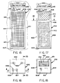
- Figure 5 is a sectional view taken along the line 5-5 of Figure 4;
- Figure 6 is an enlarged sectional view taken along the line 6-6 of Figure 4;
- Figure 7 is a sectional view taken along the line 7-7 of Figure 4;
- Figure 8 is an electrical circuit diagram for the heater, fans and lights of the dryer of Figure 1.
- Figure 9 is a front elevational view of a modification of the boot dryer;
- Figure 10 is a top plan view of Figure 9;
- Figure 11 is a sectional view taken along the line 11-11 of Figure 10;
- Figure 12 is an enlarged sectional view taken along the line 12-12 of Figure 11;
- Figure 13 is an enlarged sectional view taken along the line 12-12 of Figure 10;
- Figure 14 is a sectional view similar to Figure 6, showing a modification of the dryer of Figures 1 - 8.
- Figure 15 is a front elevational view of a modification of the dryer of the invention located in a room, such as a locker room, to dry equipment and air in the locker room and reduce odors therein;
- Figure 16 is a top plan view of Figure 15;
- Figure 17 is a sectional view taken along the line 17-17 of Figure 16;
- Figure 18 is a sectional view taken along the line 18-18 of Figure 17;
- Figure 19 is a sectional view taken along the line 19-19 of Figure 16;
- Figure 20 is a front elevational view of a third modification of the dryer of the invention;
- Figure 21 is a side elevational view of Figure 20;
- Figure 22 is an enlarged foreshortened sectional view taken along the line 22-22 of Figure 20;
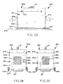
- Figure 23 is a side elevational view of a fourth modification of the dryer of the invention;
- Figure 24 is an end elevational view of the air inlet end of the dryer of Figure 23;
- Figure 25 is an end elevational view of the air outlet end of the dryer of Figure 24; and
- Figure 26 is an enlarged sectional view taken along the line 26-26 of Figure 23.
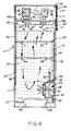
- Referring to Figures 1 and 2, there is shown the armoire or dryer of the invention indicated generally at 10.
Dryer 10 is a self-contained structure useable to dry articles and objects including, but not limited to, athletic equipment; such as hockey and baseball equipment, shoes, skates, in-line roller blade-type skates, hand and footwear, boots, socks, recreational and sports clothing and outdoor wear, sweaters, stockings and shirts that at times accumulate body perspiration or fluids, and become damp and wet in inclement weather or wet during laundry cleaning. The term "articles", as used herein, includes, but is not limited to, clothing, athletic equipment and outdoor wear and includes other products and objects that can be dried. -
Dryer 10 has a generally rectangular cabinet orhousing 11, includingupright side walls upright back wall 14. A horizontaltop wall 16 closes the top of the housing. The front of the housing has a lowerfront panel 17 located below a pair ofdoors doors side walls arrows housing 11. Handles or knobs 21 and 22, attached todoors doors - As seen in Figure 3,
peg boards doors Boards chamber 41 ofhousing 11. For example, shelves can be used for flat drying of sweaters, shirts and other garments. - Referring to Figure 2, the upper part of
back wall 14 carries threefilters holders 34 attachfilters wall 14. Anelectrical cord 36 extends throughback wall 14 belowfilters Cord 36 is connected to a groundfault circuit breaker 100, shown in Figure 8. - As seen in Figure 4, a bottom wall or
floor 37 is attached to lower portions ofside walls back wall 14.Bottom wall 37 has a largecentral opening 38 accommodating adrip pan 39.Drip pan 39 has an open top to accommodate any water, ice or snow that is derived from the articles to be dried withinhousing 11. The articles are located within a drying chamber, indicated generally at 41, located abovedrip pan 39. The upper part ofhousing 11 has a ceiling ortransverse wall 42 located below anair mixing chamber 43, as seen in Figure 6. - The inside of
back wall 14 accommodates a generallyrectangular peg board 44 and alower peg board 46.Boards Peg boards side walls horizontal shelves chamber 41, are supported onclips additional clips shelves peg board 48. Additional support structures or clips can be used to support shelves, hooks and other structures for supporting the articles withinchamber 41. - A pair of germicidal
ultraviolet light fixtures chamber 41.Fixtures transverse wall 42. The ultraviolet light emitted fromfixtures chamber 41 and limit mold, fungus, virus, mildew, dry rot and bacterial growth on the articles to be dried. - The center of
transverse wall 42 supports a light 62 and air grills 63 and 64, allowing air to circulate between dryingchamber 41 and mixingchamber 43. Backwall 14, as seen in Figure 4, has a plurality of holes oropenings filters chamber 41. A single opening inback wall 14 can be used in lieu of openings 66 - 69. A motor-driven fan (not shown) can be mounted onback wall 14 to force additional outside air into dryingchamber 41.Arrows 71 indicate the flow of air intochamber 41. Openings 66 - 69 allow outside air to flow into dryingchamber 41 so that the dryer breathes when used for storage. - A
front panel 72 closes the front portion of mixingchamber 43.Panel 72 supports atimer 103 and switches 104, 105 and 106 for controllingheater 73,ultraviolet lamps chamber 41 andair mixing chamber 43. A coin-operated mechanism (not shown) can be used to operatetimer 103. - As seen in Figure 6, a first fan or
blower 74, having a squirrel-cage impeller driven with an electric motor, operates to deliver air throughheater 73 and into dryingchamber 41, as indicated byarrows 76.Heater 73 is shown as an electric resistance coil located betweenfan 74 andair grill 63. Other types of heaters including infrared light and electronic heaters can be used to heat air directed into dryingchamber 41.Fan 74 andheater 73 can be a single device mounted oninterior wall 42. Asecond exhaust fan 77, having a squirrel-cage impeller driven with an electric motor, operates to draw air from dryingchamber 41 and discharge the air towardcharcoal air filters arrows 78. A single electric motor can be used to drivefans air filters air filters fan 77. Separate activated carbon filters can be used to cover holes 66 - 69.Fan 77 draws air from dryingchamber 41 throughair grill 64 and draws fresh, external air throughair filters chamber 41 in mixingchamber 43 and is discharged throughheater 73 andair grill 63 into the top of dryingchamber 41. The hot air from dryingchamber 41 heats up the cool, fresh air thereby reducing the amount of heat energy required byheater 73 to heat the air being forced into dryingchamber 41 byfan 74. - As seen in Figures 4 and 6, a second drying unit termed a boot dryer, indicated generally at 79, is located in the lower portion of drying
chamber 41adjacent back wall 14.Boot dryer 79 has a housing or casing 81 that is attached withfasteners 83, such as bolts, to backwall 14.Boot dryer 79 can be positioned at a selected elevation relative to backwall 14, as desired by the user of the dryer. Casing 81 has aninternal chamber 82 that is open to a plurality ofupright tubes nuts tubes nuts tubes ultraviolet lamp 95 within casing 81 emits light to the casing and throughtubes 84 and 86 - 88 to destroy contaminants in the air and articles located on the tines. Mirrors, as shown in Figure 13, reflect the UV light into the articles on the tubes. The front wall of casing 81 accommodates a pair of third and fourth fans orblowers chamber 41 intoboot dryer chamber 82 which is then forced throughtubes Fans tubes chamber 41, as indicated byarrows 99 in Figure 6, to increase air circulation within the lower portion of dryingchamber 41. A single fan can be used in lieu offans fans tubes chamber 41. - Referring to Figure 8, there is shown the electrical circuit diagram for
heater 73,fans lights dryer 10. A door-operatedswitch 101 functions to connect light 62 with the power source connected to groundfault circuit breaker 100 whendoor 18 is open.Switch 101 is normally closed whendoor 18 is open so that light 62 is ON when the articles are placed in dryingchamber 41. Whendoor 18 is closed,switch 101 is open, thereby turninglight 62 OFF.Timer 103 is directly connected to threeswitches Switch 104 is operable to connect the power toheater 73.Switch 105 is operable to connect the power to all of thefans chamber 43.Fans -
Switch 106 is electrically connected toultraviolet lights switch 102 is interposed in the line betweenswitch 106 andlights Switch 102 is normally closed whendoor 18 is closed. Whendoor 18 is open, the switch is opened so thatultraviolet lights door 18 is open. - The electrical circuit includes an
adjustable humidistat 107 that senses the humidity of the air in dryingchamber 41. When the humidity in the dryingchamber 41 is below a selected limit,humidistat 107 will automatically open and thereby terminate the power to the timer and shut the entire system OFF. The electrical circuit also includes anadjustable thermostat 108 which is normally closed. When the temperature of the air within dryingchamber 41 exceeds a pre-determined limit,thermostat 108 will open and thereby terminate the power toheater 73. The fans and ultraviolet lights remain ON. When the temperature in dryingchamber 41 drops below a selected point,heater 73 is turned ON.Thermostat 108 is adjustable to change the upper and lower limits of the air temperature within dryingchamber 41. - In use,
doors chamber 41. The articles, such as clothing, shoes and the like are placed within dryingchamber 41 on suitable trays or hangers. The boots, shoes, skates and socks are placed overtubes Ultraviolet lights switch 102 is open ortimer 103 is OFF.Light 62 is ON as door-operatedswitch 101 is closed whendoor 18 is open.Switches Timer 103 is then set to a selected time, such as 30 minutes, to provide a definite drying duration. Whenswitch 104 is closed,heater 73 operates to heat the air flowing through the heater.Switch 105, when closed, operates all offans Fan 74 drives the air from mixingchamber 43 throughheater 73 and to the upper portion of dryingchamber 41.Fan 77 draws air from dryingchamber 41 and discharges the air throughfilter 32 into the atmosphere. Part of the air drawn throughair grill 64 flows intofan 74 and is recirculated in dryingchamber 41. Outside air is also drawn throughfilters chamber 41. This air is moved byfan 77 throughheater 77 into dryingchamber 41.Fans ultraviolet lamp 95 destroys contaminants in the air and articles mounted on tubes 84 -88.Fans chamber 41 throughlateral tubes switch 106 is closed,ultraviolet lights tubes humidistat 107 will turn the system OFF.Thermostat 108 will turnheater 73 OFF when the temperature of the air exceeds a pre-determined value and turnsheater 73 ON when the air temperature drops below a set point. Thus, the dryer will not over-dry the articles located in dryingchamber 41 nor will the temperature of the air within the drying chamber exceed a selected value, as determined by the thermostat. - Referring to Figures 9 - 13, there is shown a modification of the boot dryer, indicated generally at 200, useable with
dryer 11 or independently of the dryer.Boot dryer 200 can replaceboot dryer 79 located within dryingchamber 41.Dryer 200 is used to remove moisture and odors from shoes, skates, boots, in-line roller blade-type skates, socks, gloves, mittens and other hand and footwear. -
Dryer 200 has a generallyrectangular casing 201 enclosing aninternal chamber 202. A drip pan ortray 203 is located on top of casing 201 to collect any water, snow, ice, mud or the like that may fall from the articles being dried.Tray 201 is generally pan-shaped with four laterally locatedupright bosses 204 and a peripheral outerupright side wall 205.Upright tubes tubular bosses 204 down intochamber 202. As seen in Figure 12, splitclamp collar 211, located abouttube 206, is retained thereon withbolt 212. The collar allowstube 206 to be vertically adjusted.Tube 206 can also be circumferentially located to accommodate different types and styles of articles to be placed thereon. Other types of holding structures can be used to retaintube 206 oncasing 201.Tube 206 has an uprightcontinuous passage 213 to allow air to flow throughtube 206 intochamber 202. The upper end oftube 206 has a biased orangled end 214, as shown in Figure 13, and accommodates aconvex mirror 216 or fisheye mirror.Block 217, attached totube 206 withbolt 218, supportsmirror 216 at a angle of about 45 degrees with respect to the longitudinal axis ofpassage 213. Other structures, such as a wire cage, can be used to supportmirror 216 in alignment withtube 206. The cage also functions to hold boots, shoes, socks and mittens open during drying. As seen in Figure 11, anultraviolet lamp 219, located withinchamber 202, is axially aligned withpassage 213.Lamp 219 emitsultraviolet light 221 intochamber 202. A portion of the ultraviolet light is reflected laterally bymirror 216, as shown in broken lines in Figure 13 into the interior of the article mounted ontube 206. Thus, the ultraviolet light is directed to the toe and heel sections of the boot, socks or the like that are placed ontube 206. The ultraviolet light has a germicidal and disinfectant effect on contaminants including bacteria, spores, fungus, viruses and the like that may be present in the article located ontube 206 and the air flowing therethrough.Tubes tube 206 andmirror 216.Dryer 200 can have one or more tubes having shapes to accommodate the articles to be mounted thereon. - Air is drawn into
chamber 202 withfan 222, operated withelectric motor 223. Support or stand 224 locatesfan 222 in alignment with an opening incasing 201 covered withfilter 226, such as an activated charcoal filter. A plurality offasteners 227, as seen in Figure 9, securesfilter 226 tocasing 201. A second filter, such as an activatedcarbon filter 228, is located on casing 201 and attached thereto withfasteners 229.Filter 228 covers an opening incasing 201 open tochamber 202. A second fan driven by a motor (not shown) is located behindfilter 228 to move air fromchamber 202 throughfilter 228. An example of this fan and motor isfan 222 andmotor 223, as shown in Figure 11. Other types of structures, such as blowers, impellers and the like, driven by motors, can be used to move air fromchamber 202 throughfilters - Returning to Figure 9,
timer 234 is mounted on the center portion ofcasing 201 betweenfilters Timer 234 is used to set the interval of time on the operation of thefans 222 that move the air fromchamber 202 andfilters arrows tube passage 213 intochamber 202. The external air indicated byarrow 232 can be heated with a heating coil (not shown) located within a hood (not shown) surrounding tubes 206 - 209 and articles mounted thereon. Other types of heating structures can be used to heat the air used to dry articles mounted on the tubes. A heater can be located withinchamber 202 whenfan 222 moves air out of tubes 206 - 209 and articles mounted thereon. This air picks up the moisture, as well as the odors from the article that is being dried. The air moving throughfilters arrow 231 in Figure 11. Themotors 223 for the fans are connected to an electrical power source viaswitches Switches chamber 202 and throughfilters - When
dryer 200 is used withdryer 11,motors 223 forfans 222, can be directly connected to switch 105 so that the exhaust andrecirculating fans boot dryer motors 223. - Referring to Figure 14, there is shown a dryer of the invention, indicated generally at 300, used with the central heating system of a building to dry articles of clothing, sporting equipment, athletic equipment and the like.
Dryer 300 can be used with additional identical dryers in a locker room environment to dry the sports and recreational equipment used by persons, players, coaches, referees and the like.Dryer 300 has the same structure as the dryer shown in Figures 1 - 8. The common structure has the same reference numbers with the prefix "3". The heat source is the structure's heater or furnace, illustrated asheater 373 that accommodates incoming air. Other sources of heat can be used to supply hot air todryer 300 or a group of dryers. The air is drawn through heater 273 with a fan, blower orimpeller 375 that is driven with an electric motor (not shown). The air moved byblower 375 moves into the dryingchamber 341, as indicated by arrow 371.Impeller 375 can be used to supply air through suitable ducts to additional dryers. Exhaust fan 377 delivers air throughduct 380 which can lead to an exhaust fan or external atmosphere.Duct system 380 can be returned back toheater 373, as is commonly used in a forced-air furnace system of a home. The hot air, indicated by arrow 371, moves through dryingchamber 341 and moves up into mixingchamber 342. Recirculatingfan 374 delivers air from mixingchamber 343 back into dryingchamber 341. The air is recirculated in the drying chamber to accumulate additional moisture, thereby providing effective heat energy and drying conditions. Part of the air from dryingchamber 342 is moved with exhaust fan 377 toexhaust duct 380, as shown byarrow 378.Duct 380 is connected to a short tube having aback flow damper 385 to prevent flow of air fromduct 380 back into fan 377.Duct 380 can be part of the return air system of a hot forced-air furnace or connected to tubing to direct exhaust air to the outside environment.Duct 380 can be connected to conduits having filters, such as carbon filters, to direct air back into theroom accommodating dryer 300. - Referring to Figures 15 - 19, there is shown a modification of the dryer of the invention, indicated generally at 400, located in an enclosed room, such as a locker room including, but not limited to, recreational and athletic locker rooms and industrial locker rooms. The dryer operates to remove moisture and odors from the air in the locker room thereby drying equipment fixtures and structures in the locker room.
-
Dryer 400 has a generally rectangular housing, indicated generally at 402.Housing 402 hasupright side walls upright back wall 405. The top of the housing is closed withtop wall 406.Bottom wall 407 is joined to lower portions ofside walls back wall 405. An internal generallyhorizontal wall 408 is located inside the housing.Wall 408 divides the interior of the housing into a first orlower chamber 409 and a second orupper chamber 411. The front of the housing accommodatesupright air filter 412.Air filter 412, such as a fabric or glass fiber filter, removes particulates from the air moving intofirst chamber 409.Filter 412 can be an activated carbon filter to remove odors from the air, as well as particulates. Asecond filter 413 is located across the outlet of thesecond chamber 411.Filter 413 is an activated carbon filter that removes odors from the air that is discharged intoroom 401, as indicated byarrows 434. As seen in Figure 17,filter 413 is a generally rectangular carbon filter that can be removed fromhousing 402 and replaced with a new filter. - The front of
housing 402 is closed with a generallyrectangular screen door 414.Hinges 416 pivotally mount the door onside wall 403. The screen ofdoor 414 protectsfilters - Referring to Figure 19, a dehumidifier system, indicated generally at 418, is located within
housing 402.Dehumidifier system 418 has a first or coolingcoil 419, located inchamber 409.Coil 419 is coupled tocompressor 421, driven byelectric motor 422. The compressor and motor can be a single refrigeration- combined compressor and motor. Asecond heating coil 423 is located inchamber 411 rearwardly offilter 413. Line ortube 424 connectscoils dehumidifier 418.Fan 426, driven byelectric motor 427, is located adjacentfirst coil 419.Fan 426 operates to draw air fromroom 401, as indicated byarrows 428 intochamber 409. The air flows throughcoil 419, thereby cooling the air. The moisture, including water fromcoil 419, drips down intopan 441 and flows throughtube 442 to a selected location, such as the water drain forroom 401. An ultraviolet light fixture (not shown) can be located withinchamber 409 to decontaminate the structure and air therein. -
Blower 429, located within a squirrel-type housing 431, having apassage 433 open to thesecond chamber 411, draws air, as indicated by arrows 430 fromchamber 409 and discharges the air intochamber 411. The air flows throughheating coil 423 and filter 413 into the room, as indicated byarrows 434. As the air passes throughcoil 423, it picks up heat fromcoil 423 whereby heated air is discharged intoroom 401. -
Ultraviolet lamp 436 is mounted ontop wall 406 betweenfilter 413 andcoil 423. The ultraviolet light fromlamp 436 neutralizes contaminants including bacteria in the air flowing throughchamber 411 that may accumulate onfilter 413 andcoil 423. -
Top wall 406 of the housing supportscontrol switch 437 and other controls, such as a timer (not shown), for operatingmotors motor driving impeller 432 andultraviolet light 436. Cover 438 encloses control switches 437. Cover 438 is pivotally mounted ontop wall 406 with a pair ofhinges 439, as seen in Figure 16.Top wall 406 also supports a pair ofupright tubes chamber 411 androom 401. Boots, shoes, gloves, socks and like hand and foot wear can be placed overtubes -
Ultraviolet lamp fixture 443 is mounted on the ceiling or walls ofroom 401. The light emitted from the ultraviolet lamp fixture controls the propagation of odor-causing bacterial growth on equipment, benches, floors, walls and in like places. The ultraviolet light will also kill bacteria in the air. The ultraviolet lamp fixture is adapted to be turned ON during the hours thatroom 401 is not in use.Motion sensors 444 operate to automatically shut OFF the ultraviolet light fixture if there is any movement, such as the movement of a person inroom 401. -
Dryer 400 operates to recirculate and regenerate the air in the locker room with a minimum of heat loss to the outside of the room. The dryer also reduces the humidity of the air and odors normally associated with locker rooms. The ultraviolet lights have a sanitizing effect on the air and equipment in the locker room. -
Dryer 300, shown in Figure 14, can be used in conjunction withdryer 400 to direct air back into the room. Air discharged bydryer 300 is directed intochamber 409 ofdryer 400. The air flowing throughdryer 400 removes moisture and odors from air discharged back into the room. - Referring to Figures 20 - 22, there is shown another modification of the dryer of the invention, indicated generally at 500. The
dryer 100 is a portable and collapsible structure useable in rooms, such as hotel and motel rooms, for drying and storing articles of clothing, athletic equipment, sports gear and the like. -
Dryer 500 has ahousing 501 comprisingupright side wall 502,front wall 503 andback wall 509. The side wall, front wall and back wall are made of flexible material, such as fabric, plastic or canvas. As seen in Figure 20,front wall 503 has a centralvertical zipper 504 and horizontal upper andlower zippers Zippers interior drying chamber 508 ofhousing 501. The upper portion of dryingchamber 508 accommodates horizontal rod or bar 510 used to hang up clothing and articles in dryingchamber 508. Opposite ends ofrod 510 are anchored totop member 514. The bottom ofhousing 501 is closed withbottom member 511.Bottom member 511 has a generally pan shape with uprightperipheral flange 512 forming an upwardly open pocket orrecess 513 to accommodate downwardly directed flanges orlips 518 oftop member 514.Top member 514 can be moved downwardly and attached tobottom member 511 with a plurality of hooks or latches 519 and 521 that cooperate withclips bottom member 511. - As seen in Figures 20 and 21,
top member 514 supports a pair of downwardlyopen hooks Hooks top member 514 to a support. -
Top member 514 supportsair inlet filter 524, which allows air, as indicated byarrows 543, to flow intohousing 501. The opposite side oftop member 514 supportsair outlet filter 526 that allows air to flow externally ofdryer 500, as indicated byarrows 545.Filters top member 514 supports a horizontalinterior wall 527 having anair opening 528 that allows air to flow from dryingchamber 508 intoair mixing chamber 529.Air outlet filter 526 is in communication withair mixing chamber 529. A generally centralvertical wall 531 is located inair mixing chamber 529.Wall 531 has opening 532 that directs air toheater 533.Heater 533 can be an electrical coil heater, infrared light or other type of device that heats air.Fan 534, driven withelectric motor 536, is locatedadjacent heater 533 to move air throughheater 533 and intotube 537 leading to a flexibleelongated duct 538. As seen in Figure 22,duct 538 extends downwardly adjacentback wall 509 to a boot dryer, indicated generally at 539.Duct 538 can be used to discharge air into dryingchamber 508.Boot dryer 539 is located withinbottom member 511 and accommodates boots, mittens, shoes, socks and like hand and foot wear.Boot dryer 539 has an elongatedmanifold 541 supporting a plurality ofupright tubes 542. Controls (not shown), including switches and a timer, are used to connect the fan motor to electric power. - In use, outside air, indicated by
arrows 543, is drawn throughfilter 524 by the operation offan 534.Fan 534 moves air from mixingchamber 529 intodischarge tube 537 connected toduct 538. Air flows downwardly throughduct 538 intomanifold 541 ofboot dryer 539.Tubes 542 direct the air upwardly into dryingchamber 508. The air flows through dryingchamber 508, as indicated byarrows 544, and into mixingchamber 529 where part of the air is discharged through the filter to the atmosphere. Another part of the air is drawn through inlet opening 532adjacent heater 533 and recirculated in the drying chamber. The articles supported onrod 510 are dried by the air moving through dryingchamber 508. - Referring to Figures 23 - 26, there is shown a fourth modification of the dryer of the invention, indicated generally at 600.
Dryer 600 is a movable and portable structure useable to dry and store articles, such as clothing, athletic equipment and recreational products. -
Dryer 600 has a box-shaped housing or chest, indicated generally at 601, comprisingupright side walls inlet end wall 604 and airoutlet end wall 606.Walls bottom wall 607 to enclose dryingchamber 608, as seen in Figure 26. Walls 602 - 604, 606 and 607 can be rigid structures made of wood, plastic or paper materials. Flexible plastic, fabrics or canvas can be used for walls 602 - 604, 606 and 607. The top of dryingchamber 608 is closed with a top member or cover, indicated generally at 609. Handle 611, attached to cover 609, can be used to open the cover and/or transport the dryer. Other handles and straps can be used to conveniently carry the dryer.Hinges 612 pivotally connectcover 609 toside wall 602. The opposite side ofcover 609 accommodateslatches 613 thatsecure cover 609 toside wall 603. -
Housing 601 is connected to a movable carriage comprising a pair ofwheels housing 601. Anelongated handle 617, attached tobottom wall 607, serves as a hand grip to facilitate the moving of drying 600 on a floor orsurface 618. Handle 617 can be provided with extendible and retractable structures (not shown). Handle 617 can be a rigid one-piece structure attached tobottom wall 607. - As seen in Figures 25 and 26,
end wall 606 has a central generallyrectangular grill 619 which allows the in flow of air, indicated byarrows 620, into dryingchamber 608. The air flows throughgrill 619 into mixingchamber 621, separated from dryingchamber 608 withtransverse wall 622. Filter 623, such as a charcoal filter, is mounted onwall 622 so that the air moving from mixingchamber 621 flows through filter 623, as indicated byarrows 627, into dryingchamber 608. The air is moved withfan 624, driven byelectric motor 626.Fan 624 can be a blade-type fan or an impeller fan that is operated to provide a continuous supply of air to dryingchamber 608.Heater 628 is interposed betweengrill 619 andfan 624 to heat the air moving intofan 624 through filter 623 and into dryingchamber 608. The air in dryingchamber 608 flows through exit orexhaust filter 629, mounted in the mid- portion ofair outlet walls 606.Filter 629 is preferably a charcoal filter or a filter that removes odors from the air discharged into the atmosphere. - Peg boards, or
walls having holes chamber 608.Wall 631 is located inwardly fromside wall 602 to form apassage 633 to allow air to flow from dryingchamber 608 back to mixingchamber 621.Peg board 632 is located inwardly fromside wall 603 formingpassage 634 to allow air to flow from dryingchamber 608 into mixingchamber 621. The air in mixingchamber 621 is drawn byfan 624 back into dryingchamber 608 thereby recirculating air from dryingchamber 608 through mixingchamber 621 back into dryingchamber 608. The recirculation of the air increases the moisture content of the air and improves the drying effectiveness and heat conservation efficient. Part of the air in dryingchamber 608 is recirculated back to mixingchamber 621. The remaining portion of the air is directed throughfilter 629 into the atmosphere, as indicated by arrows 623. -
Electric motor 626 andheater coil 628 are electrically connected to switch 634 mounted onend wall 604. As seen in Figure 24, anelectrical plug receptacle 636 is mounted onend wall 604 belowswitch 634. The controls formotor 626 andheater 628 can include a timer and thermostat (not shown), as disclosed bytimer 103 andthermostat 108, as shown in Figure 8. - While there has been shown and described preferred embodiments of the dryer of the invention, it is understood that changes in the structure and arrangement of structure can be made by those skilled in the art without departing from the invention. Changes in the locations, types and number of fans, heaters and ultraviolet lights and use of dehumidifiers in the dryers can be made by one skilled in the art which are equivalent to the claimed structure. The dryer can be vented to the outdoor environment with suitable ducts in lieu of exhaust filters. The invention is defined in the following claims.
Claims (10)
- Dryer for articles having a housing (11, 501 or 601) with an internal drying chamber (41, 341, 508 or 608) for accommodating articles, a door (18, 19, 318, 503 or 609) to permit access into the drying chamber to allow articles to be placed within the drying chamber, a heater (73, 533 or 628) for heating air characterized by a wall (42, 342, 527, 622, 631 or 632) within said housing providing an air mixing chamber (43, 343, 529 or 621), said wall having at least one opening (63, 64, 363, 364 or 528) to allow air to flow from the air mixing chamber into the drying chamber and out of the drying chamber into the air mixing chamber, air moving structure (74, 73, 374, 377, 534 or 624) operable to move air through said heater (73, 533 or 628) and into the drying chamber and operable to draw air from the drying chamber back into the air mixing chamber and discharge air from the air mixing chamber to the environment outside of the dryer, said housing having openings (66, 67, 68, 69, 524 or 619) to allow air to flow into the chamber and mix with the hot air discharged into the drying chamber.
- Dryer according to Claim 1 characterized by ultraviolet lights (59, 61) within said drying chamber, and a control (104, 105, 106) for connecting the ultraviolet lights to a source of electric power whereby the ultraviolet lights emit ultraviolet light which reduces contaminants in the air within the drying chamber.
- Dryer according to Claim 1 or Claim 2 characterized by a timer (103) for connecting the heater (73) and air moving structure to a power source for a selected period of time and a humidistat (107) operable in response to selected humidity of the air in the drying chamber to terminate the power to the timer.
- Dryer according to any preceding claims, characterized by a casing (81 or 381) having an internal chamber (82 or 382) located within the drying chamber, tubular members (84, 86, 87, 88 or 387) mounted on the casing open to the internal chamber and drying chamber adapted to accommodate articles to be dried, and a fan (94, 96 or 394) mounted on the casing operable to move air from the drying chamber through the internal chamber and tubular members to dry the articles thereon.
- Dryer of any preceeding claims, characterized by a filter (31, 32, 33, 526 or 629) for removing odors from air mounted on the housing and a fan (77, 534 or 624) being operable to move air from the drying chamber through the filter externally of the dryer thereby removing odors from the air.
- Dryer of any preceding claim, characterized by the housing having flexible side walls (502, 503, 509), one of said side walls (503) having the door to selectively open and close said one of said side walls to allow access to the drying chamber.
- Dryer of any preceding claim, characterized by wheels (614, 616) and a handle (617) secured to the housing (601) to facilitate movement of the dryer.
- Dryer of any preceding claim, characterized by the housing having a top member (514), a bottom member (511) and flexible side walls (502, 503, 509) secured to the top member and bottom member, and hooks (516, 517) attached to the top member for mounting the dryer on a support.
- Dryer of any preceding claim, characterized by a dehumidifier (418) located within the housing (462) having a first coil (419) in the drying chamber (409) to remove moisture from the air flowing into the drying chamber and a second coil (423) comprising the heater in the mixing chamber to heat the air flowing through the mixing chamber into the drying chamber.
- Dryer according to Claim 1, characterized by a casing (201) having an internal chamber (202), tubes (206, 207, 208, 209) attached to the casing having passages (213) open to the internal chamber for accommodating articles, a fan (222) mounted on the casing operable to move air through said tubes, internal chamber, and a opening (226, 228) in the casing to dry articles located on the tubes, said tubes having longitudinal passages (213), ultraviolet lights (219) located within said internal chamber in general alignment with the passages of the tubes, mirrors (216) mounted on the tubes in general alignment with the passages of the tubes for reflecting ultraviolet light laterally of the passages into the articles mounted on the tubes, and a control (236, 237) operable to connect the fan to a power source whereby the fan operates to move air through said tubes, internal chamber and through the opening in the casing to dry articles located on the tubes.
Applications Claiming Priority (2)
| Application Number | Priority Date | Filing Date | Title |
|---|---|---|---|
| US08/072,151 US5369892A (en) | 1993-06-04 | 1993-06-04 | Armoire |
| US72151 | 1993-06-04 |
Publications (1)
| Publication Number | Publication Date |
|---|---|
| EP0627519A1 true EP0627519A1 (en) | 1994-12-07 |
Family
ID=22105913
Family Applications (1)
| Application Number | Title | Priority Date | Filing Date |
|---|---|---|---|
| EP94630035A Withdrawn EP0627519A1 (en) | 1993-06-04 | 1994-06-02 | Armoire |
Country Status (3)
| Country | Link |
|---|---|
| US (2) | US5369892A (en) |
| EP (1) | EP0627519A1 (en) |
| CA (1) | CA2109292C (en) |
Cited By (31)
| Publication number | Priority date | Publication date | Assignee | Title |
|---|---|---|---|---|
| EP0925744A2 (en) * | 1997-12-12 | 1999-06-30 | Umberto Daldossi | Thermoventilating sanitising device for shoe-racks and wardrobes |
| AT405418B (en) * | 1995-12-05 | 1999-08-25 | Michael Ing Matheisl | Drying apparatus and process |
| EP1712671A2 (en) * | 2005-04-14 | 2006-10-18 | Jouko Sämpi | Drying chamber |
| EP1959050A1 (en) * | 2007-02-16 | 2008-08-20 | Domoplast S.r.l. | Method for drying and smoothing clothes and garment items and apparatus for carrying out such method |
| US20100132208A1 (en) * | 2007-08-03 | 2010-06-03 | Jung Wook Moon | Clothes treatiang apparatus |
| EP2213780A1 (en) * | 2009-02-02 | 2010-08-04 | LG Electronics Inc. | Clothes treating apparatus |
| EP2278060A1 (en) * | 2009-07-14 | 2011-01-26 | Flavio Pialorsi | Air recirculation device for use with a dryer |
| US20110131827A1 (en) * | 2009-12-09 | 2011-06-09 | Patrick John | Ultimate glove dryer |
| US20110146098A1 (en) * | 2009-12-23 | 2011-06-23 | Vezina Jena-Francois | Collapsible drying bag |
| US20110197464A1 (en) * | 2010-01-29 | 2011-08-18 | Dry Locker, Inc. | Ventilated portable container for sports equipment |
| ES2370468A1 (en) * | 2009-04-17 | 2011-12-16 | UNIóN PLANSECA, S.L. | Improvements in the object of the patent no. P200700921 and patent of addition n. P200701059 by: dryer-clothing clothes. (Machine-translation by Google Translate, not legally binding) |
| CN102087070B (en) * | 2009-12-07 | 2012-07-18 | 承逸工业有限公司 | Electrothermal furnace for wooden plate |
| US8250885B2 (en) | 2008-04-30 | 2012-08-28 | Lg Electronics Inc. | Laundry machine |
| US8297082B2 (en) | 2008-04-30 | 2012-10-30 | Lg Electronics Inc. | Laundry machine |
| US8522450B2 (en) | 2007-08-03 | 2013-09-03 | Lg Electronics Inc. | Clothes treating apparatus |
| US8677785B2 (en) | 2008-04-30 | 2014-03-25 | Lg Electronics Inc. | Laundry machine |
| WO2015044889A1 (en) | 2013-09-30 | 2015-04-02 | Imat S.P.A. | Multifunction modular cabinet |
| US9015955B2 (en) | 2009-12-23 | 2015-04-28 | Groupe Fitsystèmes Inc. | Collapsible drying container |
| WO2015063016A1 (en) * | 2013-11-04 | 2015-05-07 | Arcelik Anonim Sirketi | A laundry dryer with increased ventilating effectiveness |
| CN104790187A (en) * | 2015-04-21 | 2015-07-22 | 耿山 | Portable rapid dryer |
| FR3018084A1 (en) * | 2014-03-03 | 2015-09-04 | Gilles Soreau | FURNITURE ASSEMBLY FOR STORING AND DRYING CLOTHING AND SHOES |
| WO2016037873A1 (en) * | 2014-09-12 | 2016-03-17 | Koninklijke Philips N.V. | A garment care device for drying and sanitizing garments |
| CN106338190A (en) * | 2016-11-23 | 2017-01-18 | 耒阳市丁先生农业发展有限公司 | Vegetable Dewatering and Drying Equipment |
| CN107726794A (en) * | 2017-10-19 | 2018-02-23 | 安吉十万亩白茶有限公司 | A kind of Tea Production drying screening technique |
| CN109059440A (en) * | 2018-07-02 | 2018-12-21 | 郑州拓华仪器有限公司 | A kind of safe and efficient dustless hot air drier |
| DE102008028254B4 (en) * | 2007-06-13 | 2020-04-16 | Lg Electronics Inc. | Clothing treating machine and method for controlling it |
| US20200173096A1 (en) * | 2018-11-29 | 2020-06-04 | Williams Boot & Glove Dryers Inc. | Forced air drying locker |
| CN111947420A (en) * | 2020-07-03 | 2020-11-17 | 田琳琳 | Biological medicine drying equipment |
| CN112726145A (en) * | 2020-12-23 | 2021-04-30 | 珠海格力电器股份有限公司 | Machine cover seat and washing machine with same |
| US11408679B2 (en) * | 2019-09-10 | 2022-08-09 | Samsung Electronics Co., Ltd. | Shoe dryer and control method thereof |
| CN115597347A (en) * | 2022-11-01 | 2023-01-13 | 扬州工业职业技术学院(Cn) | Graphene heating device |
Families Citing this family (266)
| Publication number | Priority date | Publication date | Assignee | Title |
|---|---|---|---|---|
| NO934765L (en) * | 1993-12-22 | 1995-06-23 | Klean As | Device at wastewater treatment plant |
| US5852879A (en) * | 1995-04-26 | 1998-12-29 | Schumaier; Daniel R. | Moisture sensitive item drying appliance |
| US5592750A (en) * | 1995-09-11 | 1997-01-14 | Eichten; Gerard | Portable clothing and equipment drier |
| US5655312A (en) * | 1995-10-02 | 1997-08-12 | Fusion Uv Systems, Inc. | UV curing/drying apparatus with interlock |
| FR2742525B1 (en) * | 1995-12-19 | 1998-03-06 | Butagaz | DRYING CABIN |
| US5666743A (en) * | 1996-02-26 | 1997-09-16 | Dawson; Bonnie D. | Apparel drying and deodorizing system |
| AU2098297A (en) * | 1996-03-18 | 1997-10-10 | Jorma Komulainen | Sauna ventilation and fire prevention system |
| JP2808443B1 (en) * | 1997-04-02 | 1998-10-08 | 清川 晋 | Sauna equipment |
| US5755040A (en) * | 1997-05-09 | 1998-05-26 | Ou; Chan-Chou | Household drying center |
| US5930915A (en) * | 1997-07-14 | 1999-08-03 | Dhaemers; Gregory L. | Bag with air distributor and method for removing moisture and odors from within the bag |
| US6134806A (en) * | 1997-07-14 | 2000-10-24 | Dhaemers; Gregory L. | Bag with air distributor and ozone generator |
| US5953831A (en) * | 1997-07-28 | 1999-09-21 | Regentech Limited | Infrared-radiating clothes dryer |
| US6088932A (en) * | 1997-12-30 | 2000-07-18 | Amana Company, L.P. | Efficiency clothes dryer |
| US6018885A (en) * | 1998-03-09 | 2000-02-01 | Hill; Frederick J. | Fire and rescue equipment dryer system and method |
| US5987773A (en) * | 1998-07-27 | 1999-11-23 | Lipscy; Gordon E. | Foot and hand apparel dryer cabinet assembly |
| US6094835A (en) * | 1998-12-14 | 2000-08-01 | University Of Central Florida | Heat pump dryer with desciccant enhanced moisture removal |
| US6134810A (en) * | 1999-03-18 | 2000-10-24 | Stockley; Philip E. | Washing machine insert |
| US6497717B1 (en) | 1999-04-12 | 2002-12-24 | Visibelle Derma Institute, Inc. | Therapy steam and heat treatment cabinet |
| US6623511B1 (en) | 1999-04-12 | 2003-09-23 | Visibelle Derma Institute, Inc. | Chromatherapy shower system |
| US6094839A (en) * | 1999-05-11 | 2000-08-01 | Nikolov; Dimitar Nikolov | Footwear drying apparatus |
| US20110064607A1 (en) * | 1999-05-28 | 2011-03-17 | Thermapure, Inc. | Method for removing or treating harmful biological organisms and chemical substances |
| US8256135B2 (en) * | 1999-05-28 | 2012-09-04 | Thermapure, Inc. | Method for removing or treating harmful biological and chemical substances within structures and enclosures |
| US8221678B2 (en) * | 2002-02-20 | 2012-07-17 | Hedman David E | System and process for removing or treating harmful biological and organic substances within an enclosure |
| US8272143B1 (en) | 2002-02-20 | 2012-09-25 | David Hedman | System and process for removing or treating harmful biological and organic substances within structures and enclosures |
| DE19935984A1 (en) * | 1999-07-30 | 2001-02-01 | Bsh Bosch Siemens Hausgeraete | Device and method for deodorising and disinfecting laundry |
| US6157005A (en) * | 1999-08-30 | 2000-12-05 | Lu; Shun-Tsung | Dry-heat sauna machine |
| US6263591B1 (en) | 2000-01-25 | 2001-07-24 | Victor M. La Porte | Sports equipment drying container |
| JP3641217B2 (en) * | 2000-03-31 | 2005-04-20 | Tdk株式会社 | End electrode forming method and apparatus for chip-shaped electronic component |
| US6393725B1 (en) * | 2000-06-13 | 2002-05-28 | Electric Power Research Institute, Inc. | Compact microwave clothes dryer and method |
| DE10029428A1 (en) * | 2000-06-15 | 2002-01-03 | Bsh Bosch Siemens Hausgeraete | Air-conducting household appliance with washable filter |
| US20070266740A9 (en) | 2000-07-25 | 2007-11-22 | Kendall James W | Vertical laundry module |
| AU2001212819A1 (en) * | 2000-11-17 | 2002-05-27 | Distribuciones Tropol-Drei, S.L. | Machine for drying and ironing clothes |
| US6673097B1 (en) * | 2001-02-23 | 2004-01-06 | Hollywood Tanning Systems, Inc. | Tanning booth having reduced tanning time |
| US6745496B2 (en) * | 2001-03-20 | 2004-06-08 | Anthony Cassella | Air-flow dryer and method |
| US6693260B1 (en) * | 2001-06-04 | 2004-02-17 | Spacessories Inc. | Warming apparatus |
| DE10135471A1 (en) * | 2001-07-20 | 2003-01-30 | Bsh Bosch Siemens Hausgeraete | Tumble dryer with removable filter |
| KR100578349B1 (en) * | 2001-09-05 | 2006-05-11 | 주식회사 엘지이아이 | Air conditioning structure for dryer |
| US6779714B2 (en) * | 2001-10-29 | 2004-08-24 | Honeywell International Inc. | Biologically safe mail box |
| US7687045B2 (en) * | 2001-11-26 | 2010-03-30 | Biodefense Corporation | Article processing apparatus and related method |
| AU2002368210A1 (en) * | 2001-12-07 | 2004-05-04 | David E. Hedman | Portable decontamination unit useful in destroying harmful biological agents in contaminated objects |
| US20030124025A1 (en) * | 2002-01-03 | 2003-07-03 | Mize Gary W. | Biologically safe mailbox |
| US6679419B1 (en) * | 2002-02-01 | 2004-01-20 | Maximo Sarracino | Mailbox |
| US20030152501A1 (en) * | 2002-02-14 | 2003-08-14 | Rick Byrd | Enclosure for imparting scent to for hunting apparel |
| US6598948B1 (en) * | 2002-03-11 | 2003-07-29 | Jonathan L Harmon | Shoe storage device |
| US20050120584A1 (en) * | 2002-04-22 | 2005-06-09 | Duval Dean L. | Fabric article treating device and system |
| US6889449B2 (en) * | 2002-05-07 | 2005-05-10 | Steve Silver | Sanitizing cabinet for sports equipment |
| US6880711B2 (en) * | 2002-05-31 | 2005-04-19 | The Ultimate Group, Llc | Storage rack |
| GB2394271B (en) * | 2002-10-18 | 2005-07-13 | Nikolaos Kanavas | A locker for drying clothing |
| US6910292B2 (en) | 2003-02-06 | 2005-06-28 | Maytag Corporation | Clothes drying cabinet with improved air distribution |
| US6928752B2 (en) | 2003-04-04 | 2005-08-16 | Maytag Corporation | Combination tumble and cabinet dryer |
| US7503926B2 (en) * | 2003-05-09 | 2009-03-17 | Visibelle Derma Institute, Inc. | Combined sauna and environmental capsule |
| US20050050750A1 (en) * | 2003-07-11 | 2005-03-10 | Whiting William Scott | Footwear organizer, sanitizer, and deodorizer |
| KR100966882B1 (en) * | 2003-07-21 | 2010-06-30 | 삼성전자주식회사 | Clothing dryer |
| US6928745B2 (en) * | 2003-07-25 | 2005-08-16 | Maytag Corporation | Clothes dryer with control panel seal |
| US20050160528A1 (en) * | 2003-07-28 | 2005-07-28 | Clark Steven F. | Bed frame with integral air purifying device |
| US6992302B2 (en) * | 2003-07-29 | 2006-01-31 | Jerry Fenc | Bedding sanitizer |
| US6868621B1 (en) | 2003-08-08 | 2005-03-22 | Grimm Brothers Plastics Corp. | Clothes drying apparatus and method of drying clothes |
| CA2475811A1 (en) * | 2003-08-18 | 2005-02-18 | Jean-Pierre Deblois | Handwear and footwear dryer rack with removable portable heater |
| US6922913B2 (en) * | 2003-08-18 | 2005-08-02 | Maytag Corporation | Volatilizable media holder for a laundry dryer |
| WO2005026427A1 (en) * | 2003-09-08 | 2005-03-24 | Casella Anthony J | Drying apparatus, system and kit |
| US20050102851A1 (en) | 2003-11-15 | 2005-05-19 | Tianqing He | Device and methods for rapid drying of porous materials |
| KR101073900B1 (en) * | 2003-11-26 | 2011-10-17 | 엘지전자 주식회사 | Structure for assembling rear support and back cover in clothes dryer |
| JP3739377B2 (en) | 2003-12-10 | 2006-01-25 | シャープ株式会社 | Washing and drying machine |
| US20050166419A1 (en) * | 2003-12-31 | 2005-08-04 | Laura Regelski | Method and apparatus for drying and storing delicate clothing |
| GB2409900B (en) | 2004-01-09 | 2006-05-24 | Statoil Asa | Processing seismic data representing a physical system |
| US20050160617A1 (en) * | 2004-01-13 | 2005-07-28 | Fouts Kenneth B.Ii | Bag with active ventilation |
| US20050278983A1 (en) * | 2004-03-01 | 2005-12-22 | Maytag Corporation | Filter vent for drying cabinet |
| US6877248B1 (en) | 2004-03-05 | 2005-04-12 | Gregory N. Cross | Clothes dryer with ultraviolet light |
| US20050240248A1 (en) * | 2004-04-23 | 2005-10-27 | Venuto Ralph Sr | High pressure tanning booth |
| KR20050114107A (en) * | 2004-05-31 | 2005-12-05 | 삼성전자주식회사 | Washing machine with deodoring filter and deodoring method thereof |
| US8091253B2 (en) * | 2004-08-26 | 2012-01-10 | The Procter & Gamble Company | Fabric article treating device and system |
| US7279659B2 (en) * | 2004-09-01 | 2007-10-09 | Western Industries, Inc. | Non-food warmer appliance |
| CA2580617C (en) * | 2004-09-20 | 2009-06-23 | Martin Allen Mcfarland | Systems and methods for drying a plurality of diverse articles |
| WO2006036850A2 (en) * | 2004-09-24 | 2006-04-06 | Cissell Manufacturing Company | Clothes tumbler with ozone generator |
| US20070151303A1 (en) | 2005-12-30 | 2007-07-05 | Doyle Colleen M | Modular laundry system with work surface having a functional element |
| US20070151306A1 (en) | 2005-12-30 | 2007-07-05 | Gilboe Kevin J | Modular laundry system with work surface |
| US20070151300A1 (en) * | 2005-12-30 | 2007-07-05 | Sunshine Richard A | Modular laundry system with horizontal module spanning two laundry appliances |
| US11255040B2 (en) | 2004-10-22 | 2022-02-22 | Whirlpool Corporation | Modular laundry system |
| US20070151304A1 (en) | 2005-12-30 | 2007-07-05 | Kendall James W | Modular laundry system with work surface having a functional insert |
| US20060117810A1 (en) | 2004-10-22 | 2006-06-08 | Kendall James W | Modular Laundry system with segmented work surface |
| US7418789B2 (en) | 2004-11-10 | 2008-09-02 | Lg Electronics Inc. | Combination dryer and method thereof |
| KR100595263B1 (en) * | 2004-11-10 | 2006-07-03 | 엘지전자 주식회사 | operating method of Refresh Mode in washing device |
| KR100595234B1 (en) * | 2004-11-15 | 2006-07-03 | 엘지전자 주식회사 | method of washing device |
| KR100595240B1 (en) * | 2004-11-30 | 2006-06-30 | 엘지전자 주식회사 | complex type dryer having means for folding laundry |
| US20060137208A1 (en) * | 2004-11-30 | 2006-06-29 | Lg Electronics, Inc. | Complex type drying apparatus |
| KR100662369B1 (en) * | 2004-11-30 | 2007-01-02 | 엘지전자 주식회사 | complex type dryer having a clothes hanger for supplying heat air |
| KR100672502B1 (en) * | 2004-12-09 | 2007-01-24 | 엘지전자 주식회사 | Method of washing device |
| ITRM20040207U1 (en) * | 2004-12-22 | 2005-03-22 | Italtecno Consulting S R L | LINEN DRYER. |
| US20060248659A1 (en) * | 2004-12-30 | 2006-11-09 | Lg Electronics Inc. | Laundry device and method thereof |
| GB0515750D0 (en) | 2005-07-30 | 2005-09-07 | Dyson Technology Ltd | Drying apparatus |
| GB0515744D0 (en) * | 2005-07-30 | 2005-09-07 | Dyson Technology Ltd | Dryer |
| GB0515749D0 (en) | 2005-07-30 | 2005-09-07 | Dyson Technology Ltd | Drying apparatus |
| GB2428569B (en) | 2005-07-30 | 2009-04-29 | Dyson Technology Ltd | Dryer |
| GB0515754D0 (en) | 2005-07-30 | 2005-09-07 | Dyson Technology Ltd | Drying apparatus |
| US7171761B1 (en) * | 2005-08-02 | 2007-02-06 | Barney Dean Hunts | Large plush towel warmer and dehumidifier |
| US20070101605A1 (en) * | 2005-11-08 | 2007-05-10 | Scott Susalla | Door-side footwear container |
| US7562543B2 (en) * | 2005-12-30 | 2009-07-21 | Whirlpool Corporation | Vertical laundry module with backsplash |
| US7921578B2 (en) * | 2005-12-30 | 2011-04-12 | Whirlpool Corporation | Nebulizer system for a fabric treatment appliance |
| US7913419B2 (en) | 2005-12-30 | 2011-03-29 | Whirlpool Corporation | Non-tumble clothes dryer |
| US20070151309A1 (en) * | 2005-12-30 | 2007-07-05 | Kendall James W | Laundry module for modular laundry system |
| GB2434094A (en) | 2006-01-12 | 2007-07-18 | Dyson Technology Ltd | Drying apparatus with sound-absorbing material |
| GB2435693A (en) | 2006-02-09 | 2007-09-05 | Electromagnetic Geoservices As | Seabed electromagnetic surveying |
| DE102007007354B4 (en) | 2006-02-20 | 2013-10-10 | Lg Electronics Inc. | Clothes dryer and method of control |
| US20080256826A1 (en) * | 2006-02-23 | 2008-10-23 | Zarembinski Thomas P | Drying cabinet with ventilation system |
| US20070193058A1 (en) * | 2006-02-23 | 2007-08-23 | Zarembinski Thomas P | Drying cabinet and ventilation system |
| KR101253150B1 (en) * | 2006-04-17 | 2013-04-10 | 엘지전자 주식회사 | clothes drier and controlling methode for the same |
| DE102006020003A1 (en) * | 2006-04-26 | 2007-10-31 | Herbert Kannegiesser Gmbh | Method for recovering the heat energy emitted by laundry machines |
| US20070256322A1 (en) * | 2006-04-27 | 2007-11-08 | Daewoo Electronics Corporation | Dryer having heater-installed suction duct |
| US20070257500A1 (en) * | 2006-05-02 | 2007-11-08 | Grand Packaging, Llc | Multi-Function Sauna |
| US20070294819A1 (en) * | 2006-05-02 | 2007-12-27 | Grand Packaging, Llc | Sauna with infrared emitter |
| KR101240828B1 (en) * | 2006-05-26 | 2013-03-07 | 엘지전자 주식회사 | Method for managing the operation of a laundry room machine |
| GB2439378B (en) | 2006-06-09 | 2011-03-16 | Electromagnetic Geoservices As | Instrument for measuring electromagnetic signals |
| KR100830514B1 (en) | 2006-06-12 | 2008-05-21 | 엘지전자 주식회사 | laundry dryer and method for controlling the same |
| DE102006029960A1 (en) * | 2006-06-29 | 2008-01-03 | BSH Bosch und Siemens Hausgeräte GmbH | Dryer with reduced noise, suitable blower and impeller and method for producing the impeller |
| US20110064605A1 (en) * | 2006-07-05 | 2011-03-17 | Thermapure, Inc. | Method for treating an object contaminated with harmful biological organisms or chemical substances utilizing electromagnetic waves |
| US7716849B1 (en) * | 2006-07-12 | 2010-05-18 | Neil Hicks | Glove dryer |
| CN100554566C (en) * | 2006-08-04 | 2009-10-28 | 胡杰波 | A kind of cabinet type clothes dryer |
| US20070080613A1 (en) * | 2006-09-20 | 2007-04-12 | Sterlite Optical Technologies Ltd | Storage and transportation device for storing and transporting optical fiber preform and precursors thereof |
| GB2442749B (en) | 2006-10-12 | 2010-05-19 | Electromagnetic Geoservices As | Positioning system |
| US20080110044A1 (en) * | 2006-11-14 | 2008-05-15 | Robertshaw Controls Company | Dryer Configured for Fresh Air Induction |
| US10702623B2 (en) | 2006-11-21 | 2020-07-07 | Bluezone Ip Holding Llc | Apparatus and method for treating impurities in air and materials |
| US20080118411A1 (en) * | 2006-11-21 | 2008-05-22 | D Arinzo Ralph | Ozone deodorizing and disinfecting portable containers |
| US20080118395A1 (en) * | 2006-11-21 | 2008-05-22 | Karen Benedek | Apparatus and method for treating impurities in air and materials |
| WO2011084121A2 (en) | 2009-10-14 | 2011-07-14 | Primaira, Llc | Apparatus and method for treating impurities in air and materials |
| US8388900B2 (en) * | 2007-11-21 | 2013-03-05 | Primaira, Llc | Apparatus and method for treating impurities in air and materials |
| GB2445582A (en) | 2007-01-09 | 2008-07-16 | Statoil Asa | Method for analysing data from an electromagnetic survey |
| US7997006B2 (en) * | 2007-01-12 | 2011-08-16 | Lg Electronics Inc. | Laundry machine and control method thereof |
| JP5095240B2 (en) * | 2007-03-07 | 2012-12-12 | ハイアール グループ コーポレーション | Dryer |
| CA2584573A1 (en) * | 2007-04-11 | 2008-10-11 | Paul Regan | Storage and drying unit for storing and drying outerwear, sports clothing and equipment use |
| US20080290083A1 (en) * | 2007-05-24 | 2008-11-27 | Deruvo Peter F | Warming device |
| US20090151188A1 (en) * | 2007-08-03 | 2009-06-18 | Lg Electronics | Clothes treating apparatus |
| US8539694B2 (en) | 2007-08-03 | 2013-09-24 | Lg Electronics Inc. | Clothes treatment apparatus |
| KR101366273B1 (en) * | 2007-08-03 | 2014-02-20 | 엘지전자 주식회사 | Cloth treating apparatus |
| KR101435797B1 (en) * | 2007-08-03 | 2014-08-29 | 엘지전자 주식회사 | Cloth treating apparatus |
| KR101351042B1 (en) * | 2007-08-03 | 2014-01-10 | 엘지전자 주식회사 | Controll method of the laundry treating machine |
| KR101306714B1 (en) * | 2007-08-03 | 2013-09-11 | 엘지전자 주식회사 | device for cloth treating and method of the same |
| KR101351034B1 (en) * | 2007-08-03 | 2014-01-10 | 엘지전자 주식회사 | Laundry treating machine and controll method of the laundry treating machine |
| KR101366274B1 (en) * | 2007-08-03 | 2014-02-20 | 엘지전자 주식회사 | Laundry Treating Apparatus and Fan assembly |
| TW200914675A (en) * | 2007-09-27 | 2009-04-01 | Fu Kuang Huan | Flow-dividing device of blowing model for drying and ironing clothing |
| ITVE20070080A1 (en) * | 2007-10-25 | 2009-04-26 | Piovan Spa | INFRARED DEHUMIDIFIER |
| KR101414625B1 (en) * | 2007-11-21 | 2014-07-03 | 엘지전자 주식회사 | Dryer |
| US9808644B2 (en) | 2008-03-03 | 2017-11-07 | Visibelle Derma Institute, Inc. | Capsule with whole body LED photo-therapy system |
| US8092416B2 (en) | 2008-03-28 | 2012-01-10 | Vitalmex Internacional S.A. De C.V. | Device and method for connecting a blood pump without trapping air bubbles |
| DE102008020556A1 (en) * | 2008-04-24 | 2009-10-29 | BSH Bosch und Siemens Hausgeräte GmbH | Exhaust air dryer with reduced condensate formation and method for its operation |
| US20090283119A1 (en) * | 2008-05-16 | 2009-11-19 | Khalil Moussa | Post-Processing System For Solid Freeform Fabrication Parts |
| US20090283109A1 (en) * | 2008-05-16 | 2009-11-19 | Khalil Moussa | Methods for Cleaning and Curing Solid Freeform Fabrication Parts |
| USD617063S1 (en) | 2008-06-13 | 2010-06-01 | The Procter & Gamble Company | Fabric refreshing device |
| US20100299954A1 (en) | 2009-06-01 | 2010-12-02 | Brian Joseph Roselle | Fabric Refreshing Cabinet Device |
| US7900371B1 (en) * | 2008-07-14 | 2011-03-08 | Bullard B Wade | Personal dryer apparatus |
| US20100050462A1 (en) * | 2008-08-29 | 2010-03-04 | Joseph Francis Attonito | Body exsiccation chamber |
| US8931667B2 (en) * | 2008-09-24 | 2015-01-13 | The Procter & Gamble Company | Methods and apparatuses for dispensing fluids |
| TWM354618U (en) * | 2008-10-15 | 2009-04-11 | Feng-Yin Yang | Cool air dryer |
| TWM369349U (en) * | 2008-10-28 | 2009-11-21 | Chung Shan Inst Of Science | Disinfectant device for fabrics and shoes |
| CN102365402B (en) * | 2009-03-27 | 2013-12-18 | 宝洁公司 | Fluid dispensing system for fabric refreshing cabinet device |
| US9410281B2 (en) | 2009-05-01 | 2016-08-09 | Whirlpool Corporation | Fabric treating systems and accessories |
| US8454901B1 (en) * | 2009-05-06 | 2013-06-04 | Clarence J. Snyder, III | Mobile apparatus and method to sterilize surgical trays |
| KR101333508B1 (en) * | 2009-06-01 | 2013-11-28 | 더 프록터 앤드 갬블 캄파니 | Fabric refreshing cabinet device comprising a passive heat management system |
| CA2761485C (en) * | 2009-06-01 | 2015-10-20 | The Procter & Gamble Company | Fabric refreshing cabinet device for increasing flexural rigidity |
| US8984766B2 (en) | 2009-08-19 | 2015-03-24 | Williams Boot & Glove Dryers Inc. | Boot and glove dryer for food service industry and method of making same |
| US20110041354A1 (en) * | 2009-08-19 | 2011-02-24 | Williams Boot & Glove Dryers Inc. | Boot and glove dryer for food service industry and method of making same |
| US8245414B2 (en) * | 2009-09-02 | 2012-08-21 | General Electric Company | Drying drawer and method of drying |
| US20110074256A1 (en) * | 2009-09-25 | 2011-03-31 | Manasek Acquisition Company, Llc | Drying Locker Array For Firefighter Turnout Gear |
| US8193515B2 (en) * | 2009-10-06 | 2012-06-05 | Arthur Kreitenberg | Sports ball sterilizer |
| US20110104004A1 (en) * | 2009-11-05 | 2011-05-05 | Bobbitt Gregory C | Sport ball sanitizer |
| WO2011096968A1 (en) * | 2010-02-08 | 2011-08-11 | Danimer Scientific, Llc | Degradable polymers for hydrocarbon extraction |
| US8408013B2 (en) | 2010-06-30 | 2013-04-02 | Instrotek, Inc. | Lightweight portable moisture traps for use with vacuum pumps |
| US8438753B2 (en) | 2010-08-17 | 2013-05-14 | Josh Martin | System, method and apparatus for drying a shower |
| EP2423371A1 (en) | 2010-08-25 | 2012-02-29 | Electrolux Home Products Corporation N.V. | Laundry treating machine |
| EP2423378B1 (en) * | 2010-08-25 | 2013-04-17 | Electrolux Home Products Corporation N.V. | Laundry treating machine |
| US20120176013A1 (en) * | 2011-01-07 | 2012-07-12 | Darrel Woods | Natural Scent Storage System |
| US8526799B2 (en) * | 2011-01-18 | 2013-09-03 | Peet Shoe Dryer, Inc. | Air dehumidifier system for enclosures and safes |
| US9004306B2 (en) * | 2011-05-04 | 2015-04-14 | Pack-Rat Mini-Mover, Llc | Convertible storage container and methods for the remediation of environmentally damaged articles |
| US8793892B2 (en) | 2011-07-06 | 2014-08-05 | Rom Acquisition Corporation | Individual gear dryer system |
| US8641353B2 (en) | 2011-08-25 | 2014-02-04 | King Saud University | System for storing and retrieving shoes |
| CA2815235C (en) | 2011-11-03 | 2015-02-24 | Stan CENNON | Forced convection hanging clothes dryer |
| US20130199581A1 (en) * | 2012-02-03 | 2013-08-08 | Activar, Inc. | Equipment disinfecting and drying unit |
| US9295741B2 (en) * | 2012-03-27 | 2016-03-29 | Earl Yerby | Apparatus and method for sanitizing articles utilizing a plurality of reflector units to evenly distribute UV radiation |
| US8898925B2 (en) * | 2012-05-30 | 2014-12-02 | Jamie Zimmerman | Scent eliminating locker |
| KR101223709B1 (en) * | 2012-05-31 | 2013-01-21 | 이영진 | A hair dryer for controlling supply of amount of natural air simultaneously supplied with heating air |
| US8726539B2 (en) | 2012-09-18 | 2014-05-20 | Cambridge Engineering, Inc. | Heater and controls for extraction of moisture and biological organisms from structures |
| US9480355B2 (en) | 2012-11-27 | 2016-11-01 | Renee Kimberley Manidis | Undergarment organizing device and method of use |
| US10065278B2 (en) | 2013-01-22 | 2018-09-04 | Western Industries Incorporated | Spill resistant warming drawer |
| US8907304B2 (en) | 2013-02-27 | 2014-12-09 | Arthur Kreitenberg | Ultraviolet autonomous trolley for sanitizing aircraft |
| US10159761B2 (en) | 2013-02-27 | 2018-12-25 | Arthur Kreitenberg | Sanitizing surfaces |
| USRE49580E1 (en) | 2013-02-27 | 2023-07-18 | Dimer, Llc | Sanitizing surfaces |
| US10195298B2 (en) | 2013-02-27 | 2019-02-05 | Arthur Kreitenberg | Internal sanitizing and communicating |
| US10406253B2 (en) | 2013-02-27 | 2019-09-10 | Arthur Kreitenberg | Sanitizing surfaces associated with aircraft areas |
| US9149549B2 (en) | 2013-02-27 | 2015-10-06 | Arthur Kreitenberg | Sanitizing surfaces associated with assembly areas |
| US9144618B2 (en) | 2013-02-27 | 2015-09-29 | Arthur Kreitenberg | Sanitizing surfaces associated with seating |
| US10323882B2 (en) * | 2013-03-07 | 2019-06-18 | Daniel Durham | Sports equipment drying rack with odor mitigating enclosure |
| KR101321527B1 (en) * | 2013-03-27 | 2013-10-28 | 조철휘 | Drying apparatus utilizing heat exchanger |
| US9616143B2 (en) | 2013-07-17 | 2017-04-11 | Progressive Sterilization, Llc | Mobile apparatus and method for sterilizing one or more surgical trays with integrable transfer and storage system |
| GB2516311B (en) * | 2013-07-19 | 2016-06-29 | Dyson Technology Ltd | Motor mount |
| FR3016432B1 (en) * | 2014-01-16 | 2019-05-24 | Sunkiss Matherm Radiation | AIR RECYCLING VENTILATION ASSEMBLY FOR INFRARED RADIATION EMITTER WITH TEMPERATURE CONTROL |
| US10881997B2 (en) | 2014-01-29 | 2021-01-05 | Turbett Surgical, Inc. | Method of sterilization verification |
| US10391435B2 (en) | 2014-01-29 | 2019-08-27 | Turbett Surgical LLC | Sterilizing method and apparatus |
| US9724438B2 (en) | 2014-01-29 | 2017-08-08 | Turbett Surgical LLC | Sterilizing method and apparatus |
| US9616368B2 (en) * | 2014-01-29 | 2017-04-11 | Turbett Surgical LLC | Sterilizing method and apparatus |
| CA2933823C (en) | 2014-03-06 | 2021-04-13 | Cnh Industrial Canada, Ltd. | Dehumidifaction system and method used for drying fibers |
| WO2015153084A1 (en) | 2014-03-10 | 2015-10-08 | Pmbs, Llc | Mobile sterilization apparatus and method for using the same |
| US9918594B2 (en) * | 2014-04-10 | 2018-03-20 | Alan J. ROBERTSON | Towel rack |
| US20150297447A1 (en) * | 2014-04-18 | 2015-10-22 | Roy E. Corso | Space saving sauna with storage |
| WO2016057848A1 (en) * | 2014-10-08 | 2016-04-14 | Parker Robert M | Heated shelf apparatus and freeze dry cart using same |
| US9745687B2 (en) * | 2014-11-12 | 2017-08-29 | Jay Kenneth Miller | Heating system for a machine with a light heat source |
| GB2534176B (en) | 2015-01-15 | 2018-08-08 | Dyson Technology Ltd | Motor mount |
| CN204481158U (en) * | 2015-03-19 | 2015-07-15 | 中山市威德轻工机电制品有限公司 | Earth connection divides the sterilizer of ultraviolet radiation for water body of body nut and application thereof |
| US9322124B1 (en) * | 2015-07-01 | 2016-04-26 | Khaled J. H. Al-Hasan | Portable drier for personal articles |
| GB2543751B (en) | 2015-10-21 | 2019-04-24 | Dyson Technology Ltd | Motor mount |
| ES2780199T3 (en) * | 2016-03-21 | 2020-08-24 | Maikology Designated Activity Company | Clothes dryer and method for drying clothes |
| CN105953540A (en) * | 2016-05-25 | 2016-09-21 | 刘明月 | Special baking device for tablet-shaped traditional Chinese medicine poria cocos baking equipment |
| CN105972969A (en) * | 2016-05-25 | 2016-09-28 | 刘明月 | Baking equipment for sheet-like traditional Chinese medicine poria cocos |
| CN106196916A (en) * | 2016-07-15 | 2016-12-07 | 安庆市星胜机电设备销售有限公司 | A kind of intelligence warming dries footwear apparatus |
| US20200079482A1 (en) * | 2016-09-19 | 2020-03-12 | Brian Bowman | Apparatus for drying a wetsuit |
| US10238268B2 (en) * | 2016-09-20 | 2019-03-26 | Kairat Nurlybekov | Shoe dryer |
| US10443182B2 (en) | 2016-12-29 | 2019-10-15 | Whirlpool Corporation | Customer selection of desired remaining moisture in clothing via user interface at machine or portable electronic device |
| WO2018136046A1 (en) * | 2017-01-18 | 2018-07-26 | Psil Holdings Llc | Method and apparatus using uv-a and uv-c to treat textile materials |
| KR102280073B1 (en) * | 2017-03-07 | 2021-07-20 | 엘지전자 주식회사 | Refrigeration module and bathroom management apparatus |
| US10898604B2 (en) | 2017-03-16 | 2021-01-26 | Bluezone Ip Holding Llc | Air treatment system |
| DE202017007059U1 (en) | 2017-03-16 | 2019-06-14 | Bluezone Ip Holding Llc | Air treatment system |
| US10933159B2 (en) | 2017-03-16 | 2021-03-02 | Bluezone Ip Holding Llc | Air treatment method |
| US10933158B2 (en) | 2017-03-16 | 2021-03-02 | Bluezone Ip Holding Llc | Air treatment system and method of use |
| US10422579B2 (en) * | 2017-05-02 | 2019-09-24 | Auto Cure Llc | Automated drying and curing chamber |
| KR101939297B1 (en) * | 2017-06-02 | 2019-01-16 | 엘지전자 주식회사 | Laundry Treating Apparatus |
| US11311410B2 (en) | 2017-06-19 | 2022-04-26 | Visibelle Derma Institute, Inc. | Hyperthermic conditioning capsule |
| US20190000172A1 (en) * | 2017-06-28 | 2019-01-03 | Joshua Sahley | Helmet Dispensing System |
| US11911528B2 (en) | 2017-06-28 | 2024-02-27 | Joshua Sahley | Helmet cleaning, sanitation, and dispensing system |
| US10086100B1 (en) | 2017-07-28 | 2018-10-02 | Pmbs, Llc | Mobile sterilization apparatus and method for using the same |
| TWI646934B (en) * | 2017-08-14 | 2019-01-11 | 群光電能科技股份有限公司 | Hand dryer device |
| KR102436958B1 (en) * | 2017-09-19 | 2022-08-29 | 삼성전자주식회사 | Dryer |
| CN107806759A (en) * | 2017-09-29 | 2018-03-16 | 闫存 | A kind of layering drying unit to be processed raw material for wine |
| US10480116B2 (en) * | 2017-10-06 | 2019-11-19 | Whirlpool Corporation | Drying appliance that performs after-care cycle on a load of laundry after completion of a primary drying cycle and method for performing the after-care cycle |
| CN107764006A (en) * | 2017-10-24 | 2018-03-06 | 李媛馨 | A kind of bio-organic fertilizer sterilizing and drying device |
| US10612846B2 (en) * | 2017-12-05 | 2020-04-07 | Sam Allen | Ventilated locker |
| US11344119B2 (en) | 2017-11-06 | 2022-05-31 | Sam Allen | Ventilated locker with equipment rack |
| US10690361B2 (en) * | 2017-12-05 | 2020-06-23 | Sam Allen | Ventilated locker |
| BR202017025414Y1 (en) * | 2017-11-27 | 2022-04-26 | Mk Eletrodomésticos Mondial S.A. | Constructive arrangement introduced in a fan with a volatilizing function of a repellent substance in a tablet |
| US11723460B1 (en) | 2017-12-05 | 2023-08-15 | Aim Design, Llc | Ventilated locker with equipment rack |
| US11007290B2 (en) | 2018-01-18 | 2021-05-18 | Dimer, Llc | Flying sanitation device and method for the environment |
| KR102494999B1 (en) * | 2018-01-23 | 2023-02-02 | 삼성전자주식회사 | Clothes treating apparatus |
| US10753034B2 (en) * | 2018-01-26 | 2020-08-25 | Charles M. Dolbeare | Dryer filter cleaning apparatus and method of use |
| CN108315981A (en) * | 2018-04-11 | 2018-07-24 | 郑保华 | A kind of high effective household dryer |
| CN109028856B (en) * | 2018-06-11 | 2020-10-30 | 河南科技学院 | Intelligent art design whitewashes colouring material stoving dust collector |
| CN109520227A (en) * | 2018-11-28 | 2019-03-26 | 徐州海晟纺织有限公司 | A kind of tanning device of mixed yarn |
| US11439044B1 (en) | 2018-12-31 | 2022-09-06 | United Services Automobile Association (Usaa) | Heat recovery from data center cooling system |
| JP2022522417A (en) | 2019-02-25 | 2022-04-19 | ダイマー・エルエルシー | Mobile UV disinfection system |
| US11019922B1 (en) | 2019-06-03 | 2021-06-01 | Sam Allen | Chemical unit for locker |
| US10640910B2 (en) | 2019-06-03 | 2020-05-05 | Sam Allen | High-speed drying unit for locker |
| US10895418B1 (en) * | 2019-06-03 | 2021-01-19 | Sam Allen | High-speed drying unit for locker |
| KR20210038161A (en) * | 2019-09-30 | 2021-04-07 | 삼성전자주식회사 | Device for deodorization and dehumidification |
| KR20210049577A (en) * | 2019-10-25 | 2021-05-06 | 삼성전자주식회사 | Dryer and controlling method thereof |
| US11344016B1 (en) | 2019-11-26 | 2022-05-31 | Samuel R. Foisie | Storage case for preserving fishing rods and reels |
| US20210220496A1 (en) * | 2020-01-17 | 2021-07-22 | Lg Electronics Inc. | Shoe management device |
| US11931471B2 (en) | 2020-01-17 | 2024-03-19 | Lg Electronics Inc. | Shoe management device |
| US20210231321A1 (en) * | 2020-01-29 | 2021-07-29 | Joseph D. Gore | Heated cabinets, systems including the same, and methods of using |
| KR20210106263A (en) * | 2020-02-20 | 2021-08-30 | 엘지전자 주식회사 | Laundry Treatment Apparatus and Control Method for the same |
| US10883221B1 (en) | 2020-02-28 | 2021-01-05 | Sam Allen | Heated and cooled seat for locker |
| DE102020111233A1 (en) * | 2020-04-24 | 2021-10-28 | Gottlob Stahl Wäschereimaschinenbau GmbH | Facility for handling objects |
| WO2021232189A1 (en) * | 2020-05-18 | 2021-11-25 | Haier Us Appliance Solutions, Inc. | Low-friction drying system |
| US11369180B1 (en) * | 2020-06-19 | 2022-06-28 | Tran Thien Khanh | Manicure ventilating and sanitizing lamp |
| CN115916022A (en) * | 2020-06-24 | 2023-04-04 | Lg电子株式会社 | Shoe nursing device |
| WO2022133760A1 (en) * | 2020-12-23 | 2022-06-30 | 吴江金芙纺织整理厂 | Drying device for coating cloth production |
| CN112880326A (en) * | 2021-01-22 | 2021-06-01 | 广州达运医疗科技有限公司 | Mask raw material drying and sterilizing equipment |
| US20220249716A1 (en) * | 2021-02-11 | 2022-08-11 | Haier Us Appliance Solutions, Inc. | Laundry pedestal with ultraviolet sterilization drawer |
| US11484118B2 (en) | 2021-02-19 | 2022-11-01 | Ward Marshall Stetson | Multipurpose storage, maintenance and display cabinet system for scuba gear |
| US20220296750A1 (en) * | 2021-03-17 | 2022-09-22 | Crescent Metal Products, Inc. | Chemical-free dry heat and uvc decontamination unit and method |
| CN113310300A (en) * | 2021-07-02 | 2021-08-27 | 黄是满 | Fiber fabric air-dries device |
Citations (6)
| Publication number | Priority date | Publication date | Assignee | Title |
|---|---|---|---|---|
| US3362081A (en) * | 1965-11-29 | 1968-01-09 | Fan Way Corp | Cabinet dryer and method |
| FR1562056A (en) * | 1968-01-22 | 1969-04-04 | ||
| DE1816272A1 (en) * | 1968-12-21 | 1970-07-02 | Gmuender Erwin | Device for drying especially small amounts of laundry |
| FR2387312A1 (en) * | 1977-04-14 | 1978-11-10 | Bann Helmut | Portable hanging wardrobe with a hot air nozzle inlet - for use as a drying cabinet with air from a domestic hair dryer |
| JPS605198A (en) * | 1983-06-22 | 1985-01-11 | 松下電器産業株式会社 | Clothing dryer with hair dryer |
| EP0473567A2 (en) * | 1990-08-27 | 1992-03-04 | Mathias Stenitzer | Device for servicing shoes |
Family Cites Families (27)
| Publication number | Priority date | Publication date | Assignee | Title |
|---|---|---|---|---|
| US1755013A (en) * | 1929-01-17 | 1930-04-15 | John W Mccormick | Garment drier |
| US2232022A (en) * | 1938-08-12 | 1941-02-18 | Estes C Drake | Drier |
| US2221351A (en) * | 1939-04-11 | 1940-11-12 | Kempf Elmer | Drier |
| US2743533A (en) * | 1953-05-01 | 1956-05-01 | Maytag Co | Automatic control for clothes driers |
| US3256616A (en) * | 1962-09-19 | 1966-06-21 | Joseph M Mcgoldrick | Shoe drying apparatus |
| US3513564A (en) * | 1968-03-21 | 1970-05-26 | Robert D Gramprie | Garment,boot and mitten dryer |
| US3626602A (en) * | 1970-07-13 | 1971-12-14 | John Glowacki | Collapsible clothes dryer |
| US3739487A (en) * | 1971-01-28 | 1973-06-19 | R Clark | Drying apparatus |
| US3670425A (en) * | 1971-02-11 | 1972-06-20 | Rose Ellen Benjamin | Clothes rejuvenator |
| US3739496A (en) * | 1971-03-24 | 1973-06-19 | Mc Graw Edison Co | Steam air cabinet finisher |
| US3858331A (en) * | 1972-06-15 | 1975-01-07 | Catton Inc | Garment heating apparatus |
| US3805561A (en) * | 1972-06-29 | 1974-04-23 | Cissell W Mfg Co | Garment finishing apparatus |
| US3897638A (en) * | 1973-01-15 | 1975-08-05 | Lowell J Lenz | Sequence batch drying method |
| US3837088A (en) * | 1973-01-15 | 1974-09-24 | Lenz J & Sons Inc | Sequence batch dryer |
| US3877152A (en) * | 1973-10-03 | 1975-04-15 | Dewitt Y Gorman | Sanitizing and deodorizing apparatus |
| NL7711292A (en) * | 1976-10-18 | 1978-04-20 | Baltes Hans | PROCEDURE FOR DRYING LAUNDRY AND DRYING CUPBOARD FOR APPLYING THIS PROCEDURE. |
| US4145602A (en) * | 1977-11-09 | 1979-03-20 | Lee Richard D | Ski boot and glove warmer |
| US4471537A (en) * | 1982-01-18 | 1984-09-18 | Indesit Industria Elettrodomestici Italiana S.P.A. | Dryer apparatus having an improved air circulation |
| DE3343236A1 (en) * | 1983-11-30 | 1985-06-05 | Hans 4600 Dortmund Baltes | METHOD AND DEVICE FOR DRYING AND STERILIZING TISSUE, IN PARTICULAR SENSITIVE TISSUE |
| US4677764A (en) * | 1985-02-11 | 1987-07-07 | Cerny Gene L | Apparel drying tray |
| KR930003027B1 (en) * | 1985-10-11 | 1993-04-16 | 가쓰요시 이노우찌 | Infrared radiating sauna apparatus using heat of combustion as heat source |
| DE3632820A1 (en) * | 1986-09-26 | 1988-04-07 | Hans Baltes | METHOD FOR DRYING AND STERILIZING GOODS IN THE CLOSED CIRCUIT SYSTEM |
| US4682424A (en) * | 1986-10-16 | 1987-07-28 | Arlillian Irving | Clothes drying apparatus |
| US5416931A (en) * | 1990-02-23 | 1995-05-23 | Aromatherapy Steam Tube Company Limited | Booth |
| DE4037524A1 (en) * | 1990-11-26 | 1992-05-27 | Leybold Ag | LEAK DETECTOR |
| US5127169A (en) * | 1991-01-25 | 1992-07-07 | Maytag Corporation | Clothes dryer |
| US5152077A (en) * | 1991-08-16 | 1992-10-06 | Liang Chao Jung | Cloth drying machine |
-
1993
- 1993-06-04 US US08/072,151 patent/US5369892A/en not_active Expired - Lifetime
- 1993-10-26 CA CA002109292A patent/CA2109292C/en not_active Expired - Fee Related
-
1994
- 1994-06-02 EP EP94630035A patent/EP0627519A1/en not_active Withdrawn
- 1994-12-05 US US08/350,224 patent/US5546678A/en not_active Expired - Lifetime
Patent Citations (6)
| Publication number | Priority date | Publication date | Assignee | Title |
|---|---|---|---|---|
| US3362081A (en) * | 1965-11-29 | 1968-01-09 | Fan Way Corp | Cabinet dryer and method |
| FR1562056A (en) * | 1968-01-22 | 1969-04-04 | ||
| DE1816272A1 (en) * | 1968-12-21 | 1970-07-02 | Gmuender Erwin | Device for drying especially small amounts of laundry |
| FR2387312A1 (en) * | 1977-04-14 | 1978-11-10 | Bann Helmut | Portable hanging wardrobe with a hot air nozzle inlet - for use as a drying cabinet with air from a domestic hair dryer |
| JPS605198A (en) * | 1983-06-22 | 1985-01-11 | 松下電器産業株式会社 | Clothing dryer with hair dryer |
| EP0473567A2 (en) * | 1990-08-27 | 1992-03-04 | Mathias Stenitzer | Device for servicing shoes |
Non-Patent Citations (1)
| Title |
|---|
| DATABASE WPI Week 8519, Derwent World Patents Index; AN 85-112666 * |
Cited By (42)
| Publication number | Priority date | Publication date | Assignee | Title |
|---|---|---|---|---|
| AT405418B (en) * | 1995-12-05 | 1999-08-25 | Michael Ing Matheisl | Drying apparatus and process |
| EP0925744A2 (en) * | 1997-12-12 | 1999-06-30 | Umberto Daldossi | Thermoventilating sanitising device for shoe-racks and wardrobes |
| EP0925744A3 (en) * | 1997-12-12 | 2001-05-16 | Umberto Daldossi | Thermoventilating sanitising device for shoe-racks and wardrobes |
| EP1712671A2 (en) * | 2005-04-14 | 2006-10-18 | Jouko Sämpi | Drying chamber |
| EP1712671A3 (en) * | 2005-04-14 | 2006-12-13 | Jouko Sämpi | Drying chamber |
| EP1959050A1 (en) * | 2007-02-16 | 2008-08-20 | Domoplast S.r.l. | Method for drying and smoothing clothes and garment items and apparatus for carrying out such method |
| DE102008028254B4 (en) * | 2007-06-13 | 2020-04-16 | Lg Electronics Inc. | Clothing treating machine and method for controlling it |
| US20100132208A1 (en) * | 2007-08-03 | 2010-06-03 | Jung Wook Moon | Clothes treatiang apparatus |
| US8484860B2 (en) * | 2007-08-03 | 2013-07-16 | Lg Electronics Inc. | Clothes treating apparatus |
| US8522450B2 (en) | 2007-08-03 | 2013-09-03 | Lg Electronics Inc. | Clothes treating apparatus |
| US8387419B2 (en) | 2008-04-30 | 2013-03-05 | Lg Electronics Inc. | Laundry machine |
| US8250885B2 (en) | 2008-04-30 | 2012-08-28 | Lg Electronics Inc. | Laundry machine |
| US8677785B2 (en) | 2008-04-30 | 2014-03-25 | Lg Electronics Inc. | Laundry machine |
| US8297082B2 (en) | 2008-04-30 | 2012-10-30 | Lg Electronics Inc. | Laundry machine |
| EP2213780A1 (en) * | 2009-02-02 | 2010-08-04 | LG Electronics Inc. | Clothes treating apparatus |
| ES2370468A1 (en) * | 2009-04-17 | 2011-12-16 | UNIóN PLANSECA, S.L. | Improvements in the object of the patent no. P200700921 and patent of addition n. P200701059 by: dryer-clothing clothes. (Machine-translation by Google Translate, not legally binding) |
| EP2278060A1 (en) * | 2009-07-14 | 2011-01-26 | Flavio Pialorsi | Air recirculation device for use with a dryer |
| CN102087070B (en) * | 2009-12-07 | 2012-07-18 | 承逸工业有限公司 | Electrothermal furnace for wooden plate |
| US20110131827A1 (en) * | 2009-12-09 | 2011-06-09 | Patrick John | Ultimate glove dryer |
| US20110146098A1 (en) * | 2009-12-23 | 2011-06-23 | Vezina Jena-Francois | Collapsible drying bag |
| EP2339061A3 (en) * | 2009-12-23 | 2014-07-16 | Groupe FITSYSTEMES Inc. | Collapsible drying bag |
| US9015955B2 (en) | 2009-12-23 | 2015-04-28 | Groupe Fitsystèmes Inc. | Collapsible drying container |
| US8141268B2 (en) * | 2009-12-23 | 2012-03-27 | Vezina Jean-Francois | Collapsible drying bag |
| US20110197464A1 (en) * | 2010-01-29 | 2011-08-18 | Dry Locker, Inc. | Ventilated portable container for sports equipment |
| US8726534B2 (en) * | 2010-01-29 | 2014-05-20 | Murray Chappell | Ventilated portable container for sports equipment |
| WO2015044889A1 (en) | 2013-09-30 | 2015-04-02 | Imat S.P.A. | Multifunction modular cabinet |
| WO2015063016A1 (en) * | 2013-11-04 | 2015-05-07 | Arcelik Anonim Sirketi | A laundry dryer with increased ventilating effectiveness |
| EP2915914A1 (en) * | 2014-03-03 | 2015-09-09 | Gilles Soreau | Furniture assembly for storing and drying clothing garments and footwear |
| FR3018084A1 (en) * | 2014-03-03 | 2015-09-04 | Gilles Soreau | FURNITURE ASSEMBLY FOR STORING AND DRYING CLOTHING AND SHOES |
| CN105421008B (en) * | 2014-09-12 | 2020-06-23 | 皇家飞利浦有限公司 | Garment care device for drying and sterilizing garments |
| WO2016037873A1 (en) * | 2014-09-12 | 2016-03-17 | Koninklijke Philips N.V. | A garment care device for drying and sanitizing garments |
| CN105421008A (en) * | 2014-09-12 | 2016-03-23 | 皇家飞利浦有限公司 | A garment care device for drying and sanitizing garments |
| RU2683229C2 (en) * | 2014-09-12 | 2019-03-26 | Конинклейке Филипс Н.В. | Clothing care device for drying and disinfection of clothing |
| CN104790187A (en) * | 2015-04-21 | 2015-07-22 | 耿山 | Portable rapid dryer |
| CN106338190A (en) * | 2016-11-23 | 2017-01-18 | 耒阳市丁先生农业发展有限公司 | Vegetable Dewatering and Drying Equipment |
| CN107726794A (en) * | 2017-10-19 | 2018-02-23 | 安吉十万亩白茶有限公司 | A kind of Tea Production drying screening technique |
| CN109059440A (en) * | 2018-07-02 | 2018-12-21 | 郑州拓华仪器有限公司 | A kind of safe and efficient dustless hot air drier |
| US20200173096A1 (en) * | 2018-11-29 | 2020-06-04 | Williams Boot & Glove Dryers Inc. | Forced air drying locker |
| US11408679B2 (en) * | 2019-09-10 | 2022-08-09 | Samsung Electronics Co., Ltd. | Shoe dryer and control method thereof |
| CN111947420A (en) * | 2020-07-03 | 2020-11-17 | 田琳琳 | Biological medicine drying equipment |
| CN112726145A (en) * | 2020-12-23 | 2021-04-30 | 珠海格力电器股份有限公司 | Machine cover seat and washing machine with same |
| CN115597347A (en) * | 2022-11-01 | 2023-01-13 | 扬州工业职业技术学院(Cn) | Graphene heating device |
Also Published As
| Publication number | Publication date |
|---|---|
| US5546678A (en) | 1996-08-20 |
| CA2109292A1 (en) | 1994-12-05 |
| US5369892A (en) | 1994-12-06 |
| CA2109292C (en) | 2005-09-27 |
Similar Documents
| Publication | Publication Date | Title |
|---|---|---|
| US5369892A (en) | Armoire | |
| US20080256826A1 (en) | Drying cabinet with ventilation system | |
| US20070193058A1 (en) | Drying cabinet and ventilation system | |
| US6263591B1 (en) | Sports equipment drying container | |
| US6134806A (en) | Bag with air distributor and ozone generator | |
| CA2295511C (en) | Clothes dryer garment bag | |
| US5666743A (en) | Apparel drying and deodorizing system | |
| US9739531B2 (en) | Wardrobe for drying clothing and sports equipment | |
| US5987773A (en) | Foot and hand apparel dryer cabinet assembly | |
| US6889449B2 (en) | Sanitizing cabinet for sports equipment | |
| US6868621B1 (en) | Clothes drying apparatus and method of drying clothes | |
| CA2868699C (en) | Wardrobe for drying clothing and sports equipment | |
| US9322124B1 (en) | Portable drier for personal articles | |
| US20050193585A1 (en) | Sanitizing cabinet for sports equipment | |
| CA2740742C (en) | Apparatus for drying and sanitizing items | |
| JP2000070055A (en) | Clothing storing locker | |
| US6591517B1 (en) | Shoe dryer | |
| JP3535135B2 (en) | Drying equipment | |
| KR200187262Y1 (en) | A shoes hygiene cabinet | |
| CA2385170C (en) | Sanitizing cabinet for sports equipment | |
| CA2314815C (en) | Bag with air distributor and ozone generator | |
| JP3619203B2 (en) | Drying equipment | |
| CA3188041A1 (en) | Device for drying and/or disinfecting objects | |
| JP2000233099A (en) | Clothes storing and drying apparatus | |
| JP2529555Y2 (en) | Equipment for drying accessories |
Legal Events
| Date | Code | Title | Description |
|---|---|---|---|
| PUAI | Public reference made under article 153(3) epc to a published international application that has entered the european phase |
Free format text: ORIGINAL CODE: 0009012 |
|
| AK | Designated contracting states |
Kind code of ref document: A1 Designated state(s): AT CH DE ES FR GB IT LI SE |
|
| STAA | Information on the status of an ep patent application or granted ep patent |
Free format text: STATUS: THE APPLICATION IS DEEMED TO BE WITHDRAWN |
|
| 18D | Application deemed to be withdrawn |
Effective date: 19950608 |