EP0627317A1 - Packing case and opening method therefor - Google Patents
Packing case and opening method therefor Download PDFInfo
- Publication number
- EP0627317A1 EP0627317A1 EP94107957A EP94107957A EP0627317A1 EP 0627317 A1 EP0627317 A1 EP 0627317A1 EP 94107957 A EP94107957 A EP 94107957A EP 94107957 A EP94107957 A EP 94107957A EP 0627317 A1 EP0627317 A1 EP 0627317A1
- Authority
- EP
- European Patent Office
- Prior art keywords
- package
- ink
- ink supply
- container cartridge
- supply portion
- Prior art date
- Legal status (The legal status is an assumption and is not a legal conclusion. Google has not performed a legal analysis and makes no representation as to the accuracy of the status listed.)
- Granted
Links
Images


Classifications
-
- B—PERFORMING OPERATIONS; TRANSPORTING
- B41—PRINTING; LINING MACHINES; TYPEWRITERS; STAMPS
- B41J—TYPEWRITERS; SELECTIVE PRINTING MECHANISMS, i.e. MECHANISMS PRINTING OTHERWISE THAN FROM A FORME; CORRECTION OF TYPOGRAPHICAL ERRORS
- B41J2/00—Typewriters or selective printing mechanisms characterised by the printing or marking process for which they are designed
- B41J2/005—Typewriters or selective printing mechanisms characterised by the printing or marking process for which they are designed characterised by bringing liquid or particles selectively into contact with a printing material
- B41J2/01—Ink jet
- B41J2/17—Ink jet characterised by ink handling
- B41J2/175—Ink supply systems ; Circuit parts therefor
- B41J2/17503—Ink cartridges
- B41J2/17533—Storage or packaging of ink cartridges
-
- B—PERFORMING OPERATIONS; TRANSPORTING
- B65—CONVEYING; PACKING; STORING; HANDLING THIN OR FILAMENTARY MATERIAL
- B65D—CONTAINERS FOR STORAGE OR TRANSPORT OF ARTICLES OR MATERIALS, e.g. BAGS, BARRELS, BOTTLES, BOXES, CANS, CARTONS, CRATES, DRUMS, JARS, TANKS, HOPPERS, FORWARDING CONTAINERS; ACCESSORIES, CLOSURES, OR FITTINGS THEREFOR; PACKAGING ELEMENTS; PACKAGES
- B65D77/00—Packages formed by enclosing articles or materials in preformed containers, e.g. boxes, cartons, sacks or bags
- B65D77/003—Articles enclosed in rigid or semi-rigid containers, the whole being wrapped
-
- B—PERFORMING OPERATIONS; TRANSPORTING
- B65—CONVEYING; PACKING; STORING; HANDLING THIN OR FILAMENTARY MATERIAL
- B65D—CONTAINERS FOR STORAGE OR TRANSPORT OF ARTICLES OR MATERIALS, e.g. BAGS, BARRELS, BOTTLES, BOXES, CANS, CARTONS, CRATES, DRUMS, JARS, TANKS, HOPPERS, FORWARDING CONTAINERS; ACCESSORIES, CLOSURES, OR FITTINGS THEREFOR; PACKAGING ELEMENTS; PACKAGES
- B65D77/00—Packages formed by enclosing articles or materials in preformed containers, e.g. boxes, cartons, sacks or bags
- B65D77/04—Articles or materials enclosed in two or more containers disposed one within another
Definitions
- the present invention relates to a packing case and an opening method therefor for an exchangeable ink cartridge for containing ink to be supplied to a recording head, the container being detachably mounted to an ink jet recording head.
- Types of ink cartridge detachably mountable relative to an ink jet recording apparatus are classified into two groups. In one of them, it is connected with a recording head fixedly mounted on a recording apparatus, through a flexible tube, and it is detachably mountable to the recording apparatus.
- a flexible generally flat bladder is accommodated in a casing of plastic material, and the bladder is provided with a jointing portion of an elastic material for supplying the ink out.
- the ink is contained in the sealed bladder.
- Such an ink cartridge can be put on market or transported without paying particular attention to the structure of a package therefor.
- an ink cartridge is integrally constituted by a recording head and an ink container, and the integral ink cartridge is detachably mountable to an apparatus as a unit.
- This type is used, since downsizing is possible.
- An ink cartridge generally, is provided with an ink absorbing material, and is provided with an air vent for fluid communication between the inside of the ink container and the outside thereof to permit supply of the ink therein.
- the recording head is provided with an ink ejection outlet or outlets, and therefore, the possibility that the ink leaks out through the ink ejection outlet or the air vent, is not avoidable.
- both of the ink ejection outlet and the air vent or only the ink ejection outlet when the air vent has a structure for preventing the ink leakage is sealed by an elastic material or an adhesive sealing tape. It is contained in a rigid casing, and an opening of the casing is covered with a covering member having a property of preventing water introduction. Then, it is packaged and put on the market.
- the portion of the sealing tape sealing the air vent is first opened, and only then, the sealing tape portion for the ink ejection outlet is removed preferably, to assure the safe removal of the sealing tape in case that the internal pressure of the ink container is increased due to ambient condition change (pressure change or temperature change) or due to the transportation thereof.
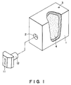
- FIG. 1 there is shown such an ink container cartridge of this type.
- An outer wall of the container cartridge 1 is provided with an ink supply port 2 for supplying the ink to a recording head 11.
- an ink supply tube 12 is connected with an ink supply port 2
- a liquid passage is established between the ink container cartridge 1 and the recording head 11.
- the ink supply port and the ink supply tube 12 are connected with an unshown connecting tube.
- An air vent 3 is formed through an outer wall of the ink container cartridge 1 to permit introduction of the air thereinto.
- the inside of the ink container 1 is filled with an ink retaining material 4.
- the material of the ink retaining material 4 include felt, porous material having continuous pores, or the like. Particularly, it is preferable to use sponge of polyurethane foam or the like because it is easy to adjust the ink retaining power.
- the ink supply port 2, and preferably the air vent 3 also, are required to be hermetically sealed to prevent ink leakage or ink evaporation until it is connected with the ink supply tube 12 of the recording head 11 for use, that is, during the transportation or storage thereof before the use thereof.
- a sealing tape 5 is generally used.
- the sealing tape 5 is a barrier material (so-called in the field of packing).
- a material similar to the body of the container cartridge 1 is used as a bonding layer for the barrier material, so that the bonding layer is fused to increase the sealing property. This is preferable.
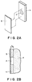
- Figures 2A and 2B illustrate prior art of the sealing of the ink supply port 2 using a sealing tape 5.
- Figure 2A is a perspective view illustrating a sealing tape 5 and a wall 1a of the container cartridge 1 which has the ink supply port 2.
- Figure 2B is a sectional view of the ink supply port 2 in the state that it is sealed by the sealing tape 5.
- the shock upon the removal of the sealing tape 5, or pressing by the fingers to the container cartridge 1 upon the removal of the sealing tape 5, may result in the scattering of the ink.
- the removal operation of the sealing tape 5 has to be carried out with quite high care, thus deteriorating the operativity.
- the structure of the ink container cartridge described hereinbefore is used as the structure of the container cartridge, there arises a problem from the standpoint of the ink supply to the recording head (it is difficult to produce a desired negative pressure).
- the structure of the ink supply port becomes bulky with cost increase.
- a package material for accommodating a container cartridge provided with an ink supply portion integral with a recording head in use comprising: a package material for accommodating the container cartridge, provided with opening means for permitting opening of the package material; a sealing material for sealing an ink supply portion of the container cartridge; wherein the sealing member is at least partly mounted to the package material.
- a method of opening a package accommodating a container cartridge provided with an ink supply portion which is integral with a recording head in use comprising: exposing only a part of the container cartridge by opening the passage; removing a sealing member which is integral with a packing material by taking the container cartridge out of the package material.
- an ink container cartridge having a small volume of a space in which the ink can occupy and from which the ink scatters upon unsealing the cartridge.
- Figure 1 is a perspective view of an example of a head cartridge and a container cartridge.
- Figures 2A and 2B illustrate a configuration of an ink supply port in a conventional ink container and a sealing for the ink supply port using a sealing tape.
- Figure 3 shows an example of a container cartridge.
- Figure 4 illustrates a configuration of an ink supply port in a container cartridge and sealing for an ink supply port by a sealing material.
- Figure 5 shows an example of a configuration of an ink supply port in a container cartridge and sealing for an ink supply port by a sealing material.
- Figure 6 shows a configuration of an ink supply port in a container cartridge and sealing for an ink supply port by a sealing material, in a further example.
- Figure 7 illustrates an example of a packing case containing a container cartridge.
- Figure 8 illustrates an example in which a packing case is opened.
- Figure 9 illustrates another example of a packing case containing a container cartridge.
- Figure 10 illustrates another example in which the packing case is opened.
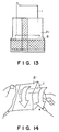
- Figure 11 illustrates a further example of a packing case containing a container cartridge.
- Figure 12 is a perspective view illustrating a method of opening the packing case of Figure 11.
- Figure 13 illustrates the packing case of Figure 11 when it is opened.
- Figure 14 illustrates the packing case of Figure 11, from which the ink cartridge is being taken out.
- Figure 15 illustrates a further example of a packing case containing a container cartridge.
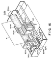
- Figure 16 is a perspective view of an example of an ink jet recording apparatus.
- FIG. 3 is a perspective view of an exchangeable container cartridge 1 to which the present invention is applied.
- the container cartridge 1 is provided at least with an ink supply port 2 for connection with an unshown ink supply tube of an ink jet recording head, and an air vent 3 for permitting introduction of the air required for the ink to be supplied out from the container cartridge 1.
- the present invention is applicable to a container cartridge 1 if it is provided with at least two openings such as an ink supply port 2 and an air vent 3, irrespective of the structure in the container cartridge 1. Accordingly, it may be a container cartridge integral with an ink jet recording head and containing porous ink retaining material in the entirety of the ink container, a container cartridge containing only ink therein, and a container cartridge in the form of a combination of the above two, which, for example, comprises an opening for connection with an ink jet recording head, a negative pressure generating material accommodating portion for accommodating a negative pressure generating material (ink absorbing material), an ink accommodating portion adjacent to the negative pressure generating material and connected therewith at a bottom.
- the present invention is suitably applicable to an ink cartridge having a negative pressure generating material accommodating portion and an ink accommodating portion.
- Figures 4A and 4B illustrate an ink container cartridge according to a first embodiment of the present invention.
- Figure 4A is a perspective view of such a wall of the container cartridge as is provided with an ink supply port 2.
- Figure 4B is a sectional view of the ink supply port 2 which is hermetically sealed by a sealing tape (material) 5.
- Designated by a reference 1a is a part of the wall provided with the ink supply port 2 in the container cartridge.
- the portion around the ink supply port 2 is provided with a thin wall portion 1a, so that the thickness of the container cartridge wall t1 is smaller than that t0 of a conventional wall of Figure 3. Therefore, the gap between the sealing tape 5 and the ink retaining member 4 at the ink supply port 2 is t1, and therefore, a volume of the space formed there is t1/t0, as compared with the conventional volume, thus reducing the volume of the space in which the ink from the ink retaining material 4 can stagnate. Therefore, the quantity of the ink stagnating there can be reduced to such an extent that the quantity of the ink scattered upon the removal of the sealing tape 5 does not result in contamination. Additionally, the waste of the ink can be avoided. In other words, the sealing tape 5 can be easily removed, thus improving the operativity.
- the container cartridge is manufactured by molding a plastic material.
- a proper wall thickness (basic wall thickness) for permitting proper molding. It is different if the material is different. For this reason, it is not preferable to reduce the thickness t1 too much. However, by reducing it as much as possible, the above described object can be accomplished.
- FIG. 4 Another configuration other than that shown in Figure 4 is usable to reduce the wall thickness of the ink container.
- the cross-section of the ink supply port 2 may be other than circular which is shown in Figure 4.
- Figure 5 illustrates a container cartridge according to another embodiment.
- Figure 5A is a perspective view of a wall portion of the container cartridge provided with the ink supply port 2.
- Figure 5B is a sectional view of an ink supply port 2 which is sealed by a sealing tape 5.
- Designated by a reference 1a is a part of a wall provided with the ink supply port 2.
- the peripheral portion of the ink supply port 2 is recessed into the container cartridge 1 (1A), so that the wall 1a is recessed into the inside by a thickness t4.
- the ink retaining material 2 is compressed in a direction of an arrow C1 by the recess 1a of the container cartridge wall.
- the ink retaining material bulges by its elasticity toward the space in the ink supply port 2 in the direction of an arrow C2.
- the space formed between the sealing tape 5 and the ink retaining member 4 in the ink supply port 2 is partly occupied by the ink retaining material 4, so that the volume of the space is reduced as compared with the conventional example shown in Figure 2. Accordingly, the volume of the space in which the ink from the ink retaining material 2 can stagnate, can be reduced.
- the degree t4 of the recess of the container wall is properly determined by one skilled in the art in accordance with the size of the ink supply port 2 and the elasticity of the ink retaining material 4, with the view to reducing the volume as much as possible.
- the configuration of the recess is not limited to that shown in Figure 5.
- the cross-section of the ink supply port 2 may be other than circular, which is shown in Figure 5.
- Figure 6 illustrates an ink container according to a further embodiment of the present invention.
- Figure 6A is a perspective view of a wall portion of the ink container provided with the ink supply port 13.
- Figure 6B is a sectional view of the ink supply port 13 which is sealed by a sealing member 16.
- Designated by a reference numeral 51 is a part of the wall provided with the ink supply port 13.
- the degree of projection is indicated by t5.
- the size of the ink retaining material 4 measured in a direction of an arrow D2 is such that it extends beyond an inside surface of the container by not less than t5.
- the ink retaining material is compressed in a direction D1, and therefore, the elasticity thereof provides such a configuration that it is bulged in a direction D2 toward the space in the ink supply port 2.
- the ink retaining material 4 partly occupies the space formed between the sealing tape 5 and the ink retaining material 4 in the ink supply port 2, so that the volume in the space is reduced as compared with the conventional example of Figure 2.
- the space permitting ink stagnation can be reduced.
- the degree of projection t5 of the ink container wall is properly determined by one skilled in the art in accordance with degree of compression in the direction D1 and the elasticity of the ink retaining material 4 and a size of the ink supply port 2, with the view to reducing the volume of the space as much as possible.
- the configuration of the projection 1a may be other than shown in Figure 6.
- the configuration of the ink supply port 2 may be non-circular, although circular example is shown in Figure 6.
- Figure 7 illustrates a container cartridge packing case according to an embodiment of the present invention.
- the openings 2 and 3 of the container cartridge 1 are sealed by a sealing tape 5.
- a fusing layer of the sealing tape 5 and a fusing layer of the packing material 21 are fused together by heat at portions indicated by 5a and 5b.
- the hatched portions in this Figure are portions of the packing case which are bonded together or another material.
- the packing case or material 21 is provided with a notch and a hole engageable with a hook 23 in a shop.
- the sealing tape and at least two openings of the container cartridge 1 may be bonded by pressure, adhesive material, fusing and/or combination thereof, provided that the sealing is enough to prevent evaporation of the ink in the container cartridge and to endure against expansion of the air or ink therein. From the standpoint of high reliability, fusing type is preferable.
- the sealing tape 5 a single layer barrier (so-called in the field of package) or a multi-layer barrier is preferably used. It is further preferable that the fusing layer of the sealing tape may be of the same or similar material as the main body of the container cartridge and/or the connecting portion of the package material. Another sealing tape material such as paper is usable, provided that the sealing is possible by pressure, bonding or fusing.
- the package material shown in Figure 7 is opened by tearing from the notch 6, as shown in Figure 8 (first opening step).
- first opening step By this, non-sealed portion of the container cartridge (without the sealing tape 4) is exposed.
- second opening step partly exposed is separated from the package material 21.
- the container cartridge 1 is rotated in a direction indicated by arrows a and b.
- the container cartridge may be pulled off the package material by one hand with the upper part of the package material 21 adjacent the sealing tape 5 being nipped by the fingers of the other hand. By doing so, the ink supply port 2 and the air vent 3 of the container cartridge is unsealed, to permit the container cartridge 1 to be taken out of the package.
- the non-seal portion of the container cartridge is exposed by the first step of the opening action.
- the container cartridge is, in effect, connected with the packing material 21 by the sealing tape 5, and therefore, the container cartridge does not pop out of the package material 21 by the first opening step. For this reason, contamination can be prevented even if the container cartridge is let fall thereafter. It is not until after the second opening step that the container cartridge is taken out.
- the sealing tape 5 is removed from the opening of the container cartridge, the openings 2 and 3 of the container cartridge are still within the package material.
- the ink scatters only into the package material so that the result is only the contamination of the inside of the package material, without contamination of the operator's hand or wear.
- the package is perforated at 24.
- the first opening step is facilitated, and it is assured that the first step of the opening results in exposing only a corner portion of the container cartridge.
- the exposed corner portion of the container cartridge is nipped, and a lower portion of the package is nipped by fingers of the other hand, and thereafter, the cartridge is rotated in a direction indicated by an arrow c.
- the opening provided by the perforation 24 assures the rotational direction (c) when the cartridge is taken out of the package. In this manner, the liability of popping out of the cartridge in the first step can be assuredly prevented.
- the sealing tape is first removed from the ink supply port 2, and thereafter, it is removed from the air vent 3. Since the size of the air vent 3 is generally smaller, the scattering of the ink from the ink supply port 2 can be further reduced because the first release of the air vent 3 provides the atmospheric pressure with the inside of the ink container, and therefore, the atmospheric pressure is established in the ink container when the ink supply port 2 is released from the sealing tape. This advantageous effect is assured by the manner of the perforation formed in the package, in this embodiment. Referring to Figure 11, there is shown a package according to another embodiment of the present invention.
- one side 5a of the sealing tape 5 is fused along one side of the packing material 21.
- a tear tape 25 is bonded or fused on one complete circumferential inside surface of the packing material 21.
- the position of the tear tape 25 is such that when the package is opened about one half of the cartridge 1 is exposed so as to permit easy handling by the operator.
- An end of the tear tape 25 projects out for the easy operation.
- Designated by 26 is a printed portion for an identification mark such as bar code or the like on the package material.
- Figure 12 illustrates the opening operation.
- the package is opened.
- a part of the cartridge 1 is exposed.
- the first stage of the opening becomes easy without imparting undesirable vibration or the like to the container cartridge.
- the second opening step a portion of the package material 21 where the sealing tape 5 is fused, is nipped by the fingers of one hand, and the exposed portion of the cartridge is nipped by the fingers of the other hand, and the cartridge is rotated in a direction e, as shown in Figure 14.
- the sealing tape 5 is removed from the ink supply port 2 and the air vent 3 of the container cartridge 1, so that the container cartridge can be taken out of the package 21.
- the package is hermetically sealed.
- the hermetical sealing is not desirable, but it is desirable that the inside of the package is partly opened to the atmosphere.
- the distribution of the ink in the container cartridge is such that it is dense adjacent the ink supply port 2 to assure the ink supply to the recording head so that as small as possible amount of the ink is present adjacent the air vent 3. Therefore, it is preferable that when the sealing tape is removed from the container cartridge, it is preferable that it is removed first from the air vent 3.
- the opening of the air vent 3 having a smaller opening area than the ink supply port 2 provides the atmospheric pressure with the inside of the ink cartridge, thus properly preventing the ink discharge through the ink supply port 2.
- FIG 15 there is shown a further embodiment in which the order of removal (first the air vent 3, and then the ink supply port 2) of the sealing tape can be further preferably carried out.
- a long sealing tape 5 is used the rest of the sealing tape 5 adjacent the portion sealing the air vent 3 is returned into the package and is extended to the outside of the package, and an end 5b of the sealing tape adjacent the portion sealing the ink supply port 2 is made integral with the package material 21.
- the sealing tape 5 is removed assuredly in the order of the air vent 3 and the ink supply port 2.
- the sealing tape 5 may be further extended along the inside of the package 21 as a tear tape, as shown in Figure 11, in which case the sealing tape 25 is continuous with the tear tape.
- the removal occurs at acute angle, since then the removal can be accomplished with smaller force.
- the ink coming out of the container when the sealing tape is removed is discharged into the package case, and therefore, the discharged ink is of no problem.
- a combination of an embodiment of the ink container described hereinbefore and an embodiment of the package is desirable since then only a small quantity of the ink is discharged into a package upon the unsealing, from the standpoint of additional reliability and saving sate of ink.
- a carriage HC is provided with a pin (not shown) engageable with a helical groove 5005 of the lead screw 5004 so that the carriage HC is reciprocated in a longitudinal direction of the apparatus.
- Designated by a reference numeral 5002 is a cap for capping a front side of each of recording heads in a recording head unit to be mounted on the carriage HC. It is used for recovery of the recording head, using unshown sucking means for sucking the ink out of the capped space.
- Each of the recording heads is provided with ejection outlets directed downwardly.
- Each recording head is connected with a container cartridge T.
- the cap 5002 is moved by a driving force transmitted thereto through a gear 5041 or the like so as to cap the ejection side surface of the recording head. Adjacent the cap 5002, there is provided an unshown cleaning blade for cleaning the ejection side surface of the recording head.
- the blade is supported for vertical movement in the Figure. As for the blade, any known cleaning blade is usable.
- the capping, cleaning and sucking operations are carried out when the carriage HC has reached the home position by the lead screw 5005. However, they may be carried out at known proper timing.
- Connection pads 4502 of the recording head unit mounted on the carriage HC are electrically connected with connection pads 5031 by rotation of a coupling plate 5030 of the carriage HC.
- a volume of a space between a sealing material and an ink retaining material adjacent an ink supply port of the ink container is reduced by the structure of the wall adjacent the ink supply port, so that the quantity of the ink stagnating in the space is significantly reduced. Therefore, the quantity of the ink scattered from the ink supply port upon removal of the sealing member, can be suppressed, and therefore, the operativity is improved.
- the ink leakage or another inconvenience can be avoided during translation thereof alone, so that high reliability is assured with simple structure and low cost.
- any user can easily open the package without scattering of the ink and contamination of the wear or hand thereby.
- a package material for accommodating a container cartridge provided with an ink supply portion integral with a recording head in use includes a package material for accommodating the container cartridge, provided with opening means for permitting opening of the package material; a sealing material for sealing an ink supply portion of the container cartridge; wherein the sealing member is at least partly mounted to the package material.
Abstract
Description
- The present invention relates to a packing case and an opening method therefor for an exchangeable ink cartridge for containing ink to be supplied to a recording head, the container being detachably mounted to an ink jet recording head. Types of ink cartridge detachably mountable relative to an ink jet recording apparatus are classified into two groups. In one of them, it is connected with a recording head fixedly mounted on a recording apparatus, through a flexible tube, and it is detachably mountable to the recording apparatus. In this type, a flexible generally flat bladder is accommodated in a casing of plastic material, and the bladder is provided with a jointing portion of an elastic material for supplying the ink out. The ink is contained in the sealed bladder. Such an ink cartridge can be put on market or transported without paying particular attention to the structure of a package therefor.
- In a second type, an ink cartridge is integrally constituted by a recording head and an ink container, and the integral ink cartridge is detachably mountable to an apparatus as a unit. This type is used, since downsizing is possible.
- An ink cartridge, generally, is provided with an ink absorbing material, and is provided with an air vent for fluid communication between the inside of the ink container and the outside thereof to permit supply of the ink therein. The recording head is provided with an ink ejection outlet or outlets, and therefore, the possibility that the ink leaks out through the ink ejection outlet or the air vent, is not avoidable.
- In order to prevent the ink leakage during the transportation of the ink cartridge, both of the ink ejection outlet and the air vent or only the ink ejection outlet when the air vent has a structure for preventing the ink leakage, is sealed by an elastic material or an adhesive sealing tape. It is contained in a rigid casing, and an opening of the casing is covered with a covering member having a property of preventing water introduction. Then, it is packaged and put on the market. When the sealing tape is used, the portion of the sealing tape sealing the air vent is first opened, and only then, the sealing tape portion for the ink ejection outlet is removed preferably, to assure the safe removal of the sealing tape in case that the internal pressure of the ink container is increased due to ambient condition change (pressure change or temperature change) or due to the transportation thereof.
- Recently, for the purpose of downsizing and inexpensive ink replenishment (consuming material), and for the purpose of effective use of a recording head having a relatively long service life, a separable head cartridge and container cartridge has been proposed in which the ink container and the recording head are separable from each other.
- Referring to Figure 1, there is shown such an ink container cartridge of this type.
- An outer wall of the
container cartridge 1 is provided with anink supply port 2 for supplying the ink to a recording head 11. When anink supply tube 12 is connected with anink supply port 2, a liquid passage is established between theink container cartridge 1 and the recording head 11. In another case, the ink supply port and theink supply tube 12 are connected with an unshown connecting tube. - An
air vent 3 is formed through an outer wall of theink container cartridge 1 to permit introduction of the air thereinto. The inside of theink container 1 is filled with anink retaining material 4. By a proper ink retaining power of the retaining material, the leaking of the ink through the recording head 11 is prevented, while permitting the proper ink supply to the recording head. Examples of the material of theink retaining material 4 include felt, porous material having continuous pores, or the like. Particularly, it is preferable to use sponge of polyurethane foam or the like because it is easy to adjust the ink retaining power. - The
ink supply port 2, and preferably theair vent 3 also, are required to be hermetically sealed to prevent ink leakage or ink evaporation until it is connected with theink supply tube 12 of the recording head 11 for use, that is, during the transportation or storage thereof before the use thereof. For the purpose of this sealing, asealing tape 5 is generally used. For example, thesealing tape 5 is a barrier material (so-called in the field of packing). A material similar to the body of thecontainer cartridge 1 is used as a bonding layer for the barrier material, so that the bonding layer is fused to increase the sealing property. This is preferable. - Figures 2A and 2B illustrate prior art of the sealing of the
ink supply port 2 using asealing tape 5. Figure 2A is a perspective view illustrating asealing tape 5 and a wall 1a of thecontainer cartridge 1 which has theink supply port 2. Figure 2B is a sectional view of theink supply port 2 in the state that it is sealed by thesealing tape 5. - In Figure 2B, between the
sealing tape 5 and theink retaining material 4, there is a gap t₀ corresponding to the thickness of the wall of thecontainer cartridge 1, in theink supply port 2. Therefore, upon ambient condition change, vibration imparted thereto, or change with time, or the like during the transportation of thecontainer cartridge 1, the ink retained by the ink retaining material seeps out into the gap and stagnates there. If this occurs, the stagnated ink scatters outwardly when thesealing tape 5 is removed for the purpose of using thecontainer cartridge 1. Then, the fingers or the cloths of the operator will be contaminated. In addition, the scattered ink is wasted. In addition, even if the ambient condition change or the change with time is less, the shock upon the removal of thesealing tape 5, or pressing by the fingers to thecontainer cartridge 1 upon the removal of thesealing tape 5, may result in the scattering of the ink. In order to avoid this, the removal operation of the sealingtape 5 has to be carried out with quite high care, thus deteriorating the operativity. - If the structure of the ink container cartridge described hereinbefore is used as the structure of the container cartridge, there arises a problem from the standpoint of the ink supply to the recording head (it is difficult to produce a desired negative pressure). In addition, the structure of the ink supply port becomes bulky with cost increase.
- It is a yet further object of the present invention to provide an ink container cartridge with which the quantity of the ink scattered or discharged out of the container cartridge through an opening or openings of the cartridge is small when the opening or openings are unsealed.
- Accordingly, it is a principal object of the present invention to provide a packing case and an opening method therefor with which ink scattering from the ink supply port is avoided upon the removal of the ink sealing tape, thus facilitating the removing operation of the sealing tape.
- It is another object of the present invention to provide a container cartridge packing case which is reliable during transportation alone.
- It is a further object of the present invention to provide a packing case for a container cartridge having a simple configuration and simple structure in the connecting portion between an ink jet recording head and a container cartridge, and which does not obstruct downsizing of the ink jet recording apparatus.
- According to an aspect of the present invention, there is provided a package material for accommodating a container cartridge provided with an ink supply portion integral with a recording head in use, comprising: a package material for accommodating the container cartridge, provided with opening means for permitting opening of the package material; a sealing material for sealing an ink supply portion of the container cartridge; wherein the sealing member is at least partly mounted to the package material.
- According to another aspect of the present invention, there is provided a method of opening a package accommodating a container cartridge provided with an ink supply portion which is integral with a recording head in use, comprising: exposing only a part of the container cartridge by opening the passage; removing a sealing member which is integral with a packing material by taking the container cartridge out of the package material.
- According to a further aspect of the present invention, there is provided an ink container cartridge having a small volume of a space in which the ink can occupy and from which the ink scatters upon unsealing the cartridge.
- These and other objects, features and advantages of the present invention will become more apparent upon a consideration of the following description of the preferred embodiments of the present invention taken in conjunction with the accompanying drawings.
- Figure 1 is a perspective view of an example of a head cartridge and a container cartridge.
- Figures 2A and 2B illustrate a configuration of an ink supply port in a conventional ink container and a sealing for the ink supply port using a sealing tape.
- Figure 3 shows an example of a container cartridge.
- Figure 4 illustrates a configuration of an ink supply port in a container cartridge and sealing for an ink supply port by a sealing material.
- Figure 5 shows an example of a configuration of an ink supply port in a container cartridge and sealing for an ink supply port by a sealing material.
- Figure 6 shows a configuration of an ink supply port in a container cartridge and sealing for an ink supply port by a sealing material, in a further example.
- Figure 7 illustrates an example of a packing case containing a container cartridge.
- Figure 8 illustrates an example in which a packing case is opened.
- Figure 9 illustrates another example of a packing case containing a container cartridge.
- Figure 10 illustrates another example in which the packing case is opened.
- Figure 11 illustrates a further example of a packing case containing a container cartridge.
- Figure 12 is a perspective view illustrating a method of opening the packing case of Figure 11.
- Figure 13 illustrates the packing case of Figure 11 when it is opened.
- Figure 14 illustrates the packing case of Figure 11, from which the ink cartridge is being taken out.
- Figure 15 illustrates a further example of a packing case containing a container cartridge.
- Figure 16 is a perspective view of an example of an ink jet recording apparatus.
- The preferred embodiments of the present invention will be described in conjunction with the accompanying drawings.
- Figure 3 is a perspective view of an
exchangeable container cartridge 1 to which the present invention is applied. - As shown in Figure 3, the
container cartridge 1 is provided at least with anink supply port 2 for connection with an unshown ink supply tube of an ink jet recording head, and anair vent 3 for permitting introduction of the air required for the ink to be supplied out from thecontainer cartridge 1. - The present invention is applicable to a
container cartridge 1 if it is provided with at least two openings such as anink supply port 2 and anair vent 3, irrespective of the structure in thecontainer cartridge 1. Accordingly, it may be a container cartridge integral with an ink jet recording head and containing porous ink retaining material in the entirety of the ink container, a container cartridge containing only ink therein, and a container cartridge in the form of a combination of the above two, which, for example, comprises an opening for connection with an ink jet recording head, a negative pressure generating material accommodating portion for accommodating a negative pressure generating material (ink absorbing material), an ink accommodating portion adjacent to the negative pressure generating material and connected therewith at a bottom. However, the present invention is suitably applicable to an ink cartridge having a negative pressure generating material accommodating portion and an ink accommodating portion. - Figures 4A and 4B illustrate an ink container cartridge according to a first embodiment of the present invention. Figure 4A is a perspective view of such a wall of the container cartridge as is provided with an
ink supply port 2. Figure 4B is a sectional view of theink supply port 2 which is hermetically sealed by a sealing tape (material) 5. Designated by a reference 1a is a part of the wall provided with theink supply port 2 in the container cartridge. - In this embodiment, as shown in Figure 4B, the portion around the
ink supply port 2 is provided with a thin wall portion 1a, so that the thickness of the container cartridge wall t₁ is smaller than that t₀ of a conventional wall of Figure 3. Therefore, the gap between the sealingtape 5 and theink retaining member 4 at theink supply port 2 is t₁, and therefore, a volume of the space formed there is t₁/t₀, as compared with the conventional volume, thus reducing the volume of the space in which the ink from theink retaining material 4 can stagnate. Therefore, the quantity of the ink stagnating there can be reduced to such an extent that the quantity of the ink scattered upon the removal of the sealingtape 5 does not result in contamination. Additionally, the waste of the ink can be avoided. In other words, the sealingtape 5 can be easily removed, thus improving the operativity. - Normally, the container cartridge is manufactured by molding a plastic material. In this case, there exists a proper wall thickness (basic wall thickness) for permitting proper molding. It is different if the material is different. For this reason, it is not preferable to reduce the thickness t₁ too much. However, by reducing it as much as possible, the above described object can be accomplished.
- Another configuration other than that shown in Figure 4 is usable to reduce the wall thickness of the ink container. The cross-section of the
ink supply port 2 may be other than circular which is shown in Figure 4. - In this embodiment, the periphery of the
ink supply port 2 is projected into arib 2a. By doing so, the bonding of the sealingtape 5 is assured so as to prevent leakage of the ink through the bonding surface. The rib may be formed similarly around theair vent 3. Figure 5 illustrates a container cartridge according to another embodiment. Figure 5A is a perspective view of a wall portion of the container cartridge provided with theink supply port 2. Figure 5B is a sectional view of anink supply port 2 which is sealed by a sealingtape 5. Designated by a reference 1a is a part of a wall provided with theink supply port 2. - In this embodiment, as shown in Figure 5B, the peripheral portion of the
ink supply port 2 is recessed into the container cartridge 1 (1A), so that the wall 1a is recessed into the inside by a thickness t₄. By this, theink retaining material 2 is compressed in a direction of an arrow C1 by the recess 1a of the container cartridge wall. Thus, the ink retaining material bulges by its elasticity toward the space in theink supply port 2 in the direction of an arrow C2. In this manner, the space formed between the sealingtape 5 and theink retaining member 4 in theink supply port 2 is partly occupied by theink retaining material 4, so that the volume of the space is reduced as compared with the conventional example shown in Figure 2. Accordingly, the volume of the space in which the ink from theink retaining material 2 can stagnate, can be reduced. - The degree t₄ of the recess of the container wall is properly determined by one skilled in the art in accordance with the size of the
ink supply port 2 and the elasticity of theink retaining material 4, with the view to reducing the volume as much as possible. - The configuration of the recess is not limited to that shown in Figure 5. In addition, the cross-section of the
ink supply port 2 may be other than circular, which is shown in Figure 5. - Figure 6 illustrates an ink container according to a further embodiment of the present invention. Figure 6A is a perspective view of a wall portion of the ink container provided with the ink supply port 13. Figure 6B is a sectional view of the ink supply port 13 which is sealed by a sealing member 16. Designated by a reference numeral 51 is a part of the wall provided with the ink supply port 13.
- As shown in Figure 6B, in this embodiment, there is provided a projected portion 1a projected outwardly, at the periphery of the
ink supply port 2. The degree of projection is indicated by t₅. The size of theink retaining material 4 measured in a direction of an arrow D2 is such that it extends beyond an inside surface of the container by not less than t₅. The ink retaining material is compressed in a direction D1, and therefore, the elasticity thereof provides such a configuration that it is bulged in a direction D2 toward the space in theink supply port 2. In this manner, theink retaining material 4 partly occupies the space formed between the sealingtape 5 and theink retaining material 4 in theink supply port 2, so that the volume in the space is reduced as compared with the conventional example of Figure 2. Thus, the space permitting ink stagnation can be reduced. - The degree of projection t₅ of the ink container wall is properly determined by one skilled in the art in accordance with degree of compression in the direction D1 and the elasticity of the
ink retaining material 4 and a size of theink supply port 2, with the view to reducing the volume of the space as much as possible. - The configuration of the projection 1a may be other than shown in Figure 6. In addition, the configuration of the
ink supply port 2 may be non-circular, although circular example is shown in Figure 6. - The above-described embodiments may be combined properly if the volume of the space in the
ink supply port 2 can be reduced. - In the following, the description will be made as to embodiments of packing cases which can avoid contamination with ink upon unsealing.
- Figure 7 illustrates a container cartridge packing case according to an embodiment of the present invention. The
openings container cartridge 1 are sealed by a sealingtape 5. A fusing layer of the sealingtape 5 and a fusing layer of the packingmaterial 21 are fused together by heat at portions indicated by 5a and 5b. The hatched portions in this Figure are portions of the packing case which are bonded together or another material. The packing case ormaterial 21 is provided with a notch and a hole engageable with ahook 23 in a shop. The sealing tape and at least two openings of thecontainer cartridge 1 may be bonded by pressure, adhesive material, fusing and/or combination thereof, provided that the sealing is enough to prevent evaporation of the ink in the container cartridge and to endure against expansion of the air or ink therein. From the standpoint of high reliability, fusing type is preferable. - As for the sealing
tape 5, a single layer barrier (so-called in the field of package) or a multi-layer barrier is preferably used. It is further preferable that the fusing layer of the sealing tape may be of the same or similar material as the main body of the container cartridge and/or the connecting portion of the package material. Another sealing tape material such as paper is usable, provided that the sealing is possible by pressure, bonding or fusing. - The package material shown in Figure 7 is opened by tearing from the notch 6, as shown in Figure 8 (first opening step). By this, non-sealed portion of the container cartridge (without the sealing tape 4) is exposed. As a second opening step, partly exposed is separated from the
package material 21. Upon this separation, it is preferable that thecontainer cartridge 1 is rotated in a direction indicated by arrows a and b. Alternatively, the container cartridge may be pulled off the package material by one hand with the upper part of thepackage material 21 adjacent the sealingtape 5 being nipped by the fingers of the other hand. By doing so, theink supply port 2 and theair vent 3 of the container cartridge is unsealed, to permit thecontainer cartridge 1 to be taken out of the package. - In this embodiment, the non-seal portion of the container cartridge is exposed by the first step of the opening action. It should be noted that the container cartridge is, in effect, connected with the packing
material 21 by the sealingtape 5, and therefore, the container cartridge does not pop out of thepackage material 21 by the first opening step. For this reason, contamination can be prevented even if the container cartridge is let fall thereafter. It is not until after the second opening step that the container cartridge is taken out. In addition, when the sealingtape 5 is removed from the opening of the container cartridge, theopenings openings ink supply port 2, the amount of the scattered ink can be reduced. - In an embodiment of Figure 9, the package is perforated at 24. According to this embodiment, the first opening step is facilitated, and it is assured that the first step of the opening results in exposing only a corner portion of the container cartridge. Then, in the second step, the exposed corner portion of the container cartridge is nipped, and a lower portion of the package is nipped by fingers of the other hand, and thereafter, the cartridge is rotated in a direction indicated by an arrow c. As will be understood, the opening provided by the
perforation 24 assures the rotational direction (c) when the cartridge is taken out of the package. In this manner, the liability of popping out of the cartridge in the first step can be assuredly prevented. - When the direction of rotation upon the taking out of the container cartridge is limited in this manner, the sealing tape is first removed from the
ink supply port 2, and thereafter, it is removed from theair vent 3. Since the size of theair vent 3 is generally smaller, the scattering of the ink from theink supply port 2 can be further reduced because the first release of theair vent 3 provides the atmospheric pressure with the inside of the ink container, and therefore, the atmospheric pressure is established in the ink container when theink supply port 2 is released from the sealing tape. This advantageous effect is assured by the manner of the perforation formed in the package, in this embodiment. Referring to Figure 11, there is shown a package according to another embodiment of the present invention. - In this embodiment, one
side 5a of the sealingtape 5 is fused along one side of the packingmaterial 21. For easy opening of the packingmaterial 21, atear tape 25 is bonded or fused on one complete circumferential inside surface of the packingmaterial 21. The position of thetear tape 25 is such that when the package is opened about one half of thecartridge 1 is exposed so as to permit easy handling by the operator. An end of thetear tape 25 projects out for the easy operation. Designated by 26 is a printed portion for an identification mark such as bar code or the like on the package material. - In Figure 11, when the package is hang up on a hook using the
opening 23, theair vent 3 and theink supply port 2 of the container cartridge sealed by the sealingtape 5 are positioned downward. By this positioning, the ink in the container is urged by the gravity toward theink supply port 2 so that the ink is retained adjacent theink supply port 2 to permit initial proper ink supply when the cartridge is mounted to the recording head. - Figure 12 illustrates the opening operation. By removing the
tear tape 25 in a direction d, the package is opened. With this state, as shown in Figure 13, a part of thecartridge 1 is exposed. Thus, the first stage of the opening becomes easy without imparting undesirable vibration or the like to the container cartridge. In the second opening step, a portion of thepackage material 21 where the sealingtape 5 is fused, is nipped by the fingers of one hand, and the exposed portion of the cartridge is nipped by the fingers of the other hand, and the cartridge is rotated in a direction e, as shown in Figure 14. Similarly try the other embodiment, the sealingtape 5 is removed from theink supply port 2 and theair vent 3 of thecontainer cartridge 1, so that the container cartridge can be taken out of thepackage 21. By taking out the container cartridge while rotating it, strong impact to theink supply port 2 can be avoided, and therefore, the ink leakage can be effectively prevented. Even if the ink is scattered, it is scattered only in thepackage 21, and therefore, there occurs no problem of contamination to the operator. Even if the container cartridge is taken out only by pulling it without the rotational motion, the ink scatters only into the package material, and therefore, no practical problem arises. - In order to prevent leakage of the ink to the outside of the package upon an unexpected situation during the transportation in which the ink leaks out into the package, it is preferable that the package is hermetically sealed. However, from the standpoint of preventing expansion of the package under a reduced pressure upon ambient condition change, the hermetical sealing is not desirable, but it is desirable that the inside of the package is partly opened to the atmosphere. The distribution of the ink in the container cartridge is such that it is dense adjacent the
ink supply port 2 to assure the ink supply to the recording head so that as small as possible amount of the ink is present adjacent theair vent 3. Therefore, it is preferable that when the sealing tape is removed from the container cartridge, it is preferable that it is removed first from theair vent 3. When the internal pressure of thecontainer cartridge 1 sealed by thetape 5 is high due to the ambient condition (temperature and pressure change), the opening of theair vent 3 having a smaller opening area than theink supply port 2 provides the atmospheric pressure with the inside of the ink cartridge, thus properly preventing the ink discharge through theink supply port 2. - Referring to Figure 15, there is shown a further embodiment in which the order of removal (first the
air vent 3, and then the ink supply port 2) of the sealing tape can be further preferably carried out. In this embodiment, along sealing tape 5 is used the rest of the sealingtape 5 adjacent the portion sealing theair vent 3 is returned into the package and is extended to the outside of the package, and anend 5b of the sealing tape adjacent the portion sealing theink supply port 2 is made integral with thepackage material 21. - When the package is opened, a part of the
package 21 is opened, and then, theend 5a extended to the outside is pulled in a direction f. Then, the sealing tape is removed assuredly in the order of theair vent 3 and theink supply port 2. Alternatively, before thepackage material 21 is opened, the sealingtape 5 is removed from theair vent 3 and theink supply port 2 in the order named, and thereafter, thepackage 21 is opened. In this case, the sealingtape 5 may be further extended along the inside of thepackage 21 as a tear tape, as shown in Figure 11, in which case the sealingtape 25 is continuous with the tear tape. - As regards the direction of removing the sealing tape from the opening of the container cartridge, it is preferable that the removal occurs at acute angle, since then the removal can be accomplished with smaller force.
- In the embodiment of Figure 15, the direction of removal is close to 180 degrees. Referring to Figure 16, there is shown in a perspective view an example of an ink jet recording apparatus IJRA usable with the container cartridge described in the foregoing.
- According to the foregoing embodiments of the package case, the ink coming out of the container when the sealing tape is removed is discharged into the package case, and therefore, the discharged ink is of no problem. However, a combination of an embodiment of the ink container described hereinbefore and an embodiment of the package, is desirable since then only a small quantity of the ink is discharged into a package upon the unsealing, from the standpoint of additional reliability and saving sate of ink.
- In this Figure, forward or backward rotation of a driving
motor 5013 is transmitted to alead screw 5004 through drive transmission gears 5011 and 5009 to rotate thelead screw 5004. A carriage HC is provided with a pin (not shown) engageable with ahelical groove 5005 of thelead screw 5004 so that the carriage HC is reciprocated in a longitudinal direction of the apparatus. Designated by areference numeral 5002 is a cap for capping a front side of each of recording heads in a recording head unit to be mounted on the carriage HC. It is used for recovery of the recording head, using unshown sucking means for sucking the ink out of the capped space. Each of the recording heads is provided with ejection outlets directed downwardly. Each recording head is connected with a container cartridge T. Thecap 5002 is moved by a driving force transmitted thereto through agear 5041 or the like so as to cap the ejection side surface of the recording head. Adjacent thecap 5002, there is provided an unshown cleaning blade for cleaning the ejection side surface of the recording head. The blade is supported for vertical movement in the Figure. As for the blade, any known cleaning blade is usable. - The capping, cleaning and sucking operations are carried out when the carriage HC has reached the home position by the
lead screw 5005. However, they may be carried out at known proper timing. -
Connection pads 4502 of the recording head unit mounted on the carriage HC are electrically connected withconnection pads 5031 by rotation of acoupling plate 5030 of the carriage HC. - As described in the foregoing, according to the present invention, a volume of a space between a sealing material and an ink retaining material adjacent an ink supply port of the ink container, is reduced by the structure of the wall adjacent the ink supply port, so that the quantity of the ink stagnating in the space is significantly reduced. Therefore, the quantity of the ink scattered from the ink supply port upon removal of the sealing member, can be suppressed, and therefore, the operativity is improved.
- According to another aspect of the present invention, the ink leakage or another inconvenience can be avoided during translation thereof alone, so that high reliability is assured with simple structure and low cost.
- In addition, any user can easily open the package without scattering of the ink and contamination of the wear or hand thereby.
- While the invention has been described with reference to the structures disclosed herein, it is not confined to the details set forth and this application is intended to cover such modifications or changes as may come within the purposes of the improvements or the scope of the following claims.
- A package material for accommodating a container cartridge provided with an ink supply portion integral with a recording head in use includes a package material for accommodating the container cartridge, provided with opening means for permitting opening of the package material; a sealing material for sealing an ink supply portion of the container cartridge; wherein the sealing member is at least partly mounted to the package material.
Claims (19)
- A package material for accommodating a container cartridge provided with an ink supply portion integral with a recording head in use, comprising:
a package material for accommodating the container cartridge, provided with opening means for permitting opening of said package material;
a sealing material for sealing an ink supply portion of the container cartridge;
wherein said sealing member is at least partly mounted to said package material. - A package according to Claim 1, wherein said opening means is a notch formed in a part of said package material to permit only a part of the container cartridge remote from the ink supply portion to the exposed, when the package is opened.
- A package according to Claim 1, wherein said opening means is a perforation in said package to permit only a part of the container cartridge remote from the ink supply portion is exposed, when the package is opened.
- A package according to Claim 1, wherein said opening means is a tape in said package material to permit only a part of the container cartridge remote from the ink supply portion to be exposed when the package is opened.
- A package according to Claim 1, wherein said sealing material is in the form of a tape, and one or both of longitudinal ends thereof are fused to the package material.
- A package according to Claim 1, wherein said sealing material is in the form of a tape, and one lateral side is fused to the package material, and the other lateral end portion seals the ink supply portion.
- A package according to Claim 1, wherein the package material is provided with an opening, and wherein the ink supply portion is located most remote from the opening.
- A package according to Claim 1, wherein said container cartridge is provided with an air vent, and wherein said sealing member also seals the air vent.
- A package according to Claim 1, wherein a wall thickness of the ink supply portion of the container cartridge is smaller than a thickness of a wall portion therearound to provide a volume of the ink supply portion.
- A package according to Claim 1, wherein said container cartridge contains an ink absorbing material which is deformed by its elasticity into the ink supply portion.
- A package according to Claim 1, wherein the ink supply portion is enclosed with a rib projecting outwardly.
- A package according to Claim 8, wherein the air vent is enclosed with a rib projected outwardly.
- A method of opening a package accommodating a container cartridge provided with an ink supply portion which is integral with a recording head in use, comprising:
exposing only a part of the container cartridge by opening the passage;
removing a sealing member which is integral with a packing material by taking the container cartridge out of the package material. - A method according to Claim 13, wherein said opening step and removing step are carried out in this order.
- A method according to Claim 13, wherein said opening step is carried out after said removing step.
- A method according to Claim 13, wherein a rotational motion is imparted between said package material and said container cartridge in said removing step.
- A method according to Claim 13, wherein the container cartridge is pulled in said removing step.
- A method according to Claim 13, wherein the container cartridge is provided with an air vent, and said removing step is effected for the ink supply portion and for the air vent.
- A method according to Claim 13, wherein said container cartridge is provided with an air vent, and wherein said removing step is effected for the air vent and for the ink supply portion in the order named.
Applications Claiming Priority (6)
| Application Number | Priority Date | Filing Date | Title |
|---|---|---|---|
| JP12262193A JP3165281B2 (en) | 1993-05-25 | 1993-05-25 | Package of replaceable ink jet recording ink cartridge and method of opening the same |
| JP122946/93 | 1993-05-25 | ||
| JP12294693A JP3334942B2 (en) | 1993-05-25 | 1993-05-25 | Ink tank, inkjet cartridge and inkjet recording device |
| JP122621/93 | 1993-05-25 | ||
| JP22348993A JP3372600B2 (en) | 1993-09-08 | 1993-09-08 | Packing member and opening method of packing member |
| JP223489/93 | 1993-09-08 |
Publications (2)
| Publication Number | Publication Date |
|---|---|
| EP0627317A1 true EP0627317A1 (en) | 1994-12-07 |
| EP0627317B1 EP0627317B1 (en) | 1998-08-12 |
Family
ID=27314487
Family Applications (1)
| Application Number | Title | Priority Date | Filing Date |
|---|---|---|---|
| EP94107957A Expired - Lifetime EP0627317B1 (en) | 1993-05-25 | 1994-05-24 | Packing case and opening method therefor |
Country Status (10)
| Country | Link |
|---|---|
| US (1) | US5701995A (en) |
| EP (1) | EP0627317B1 (en) |
| KR (1) | KR0137620B1 (en) |
| CN (1) | CN1081546C (en) |
| AT (1) | ATE169566T1 (en) |
| AU (1) | AU671539B2 (en) |
| CA (1) | CA2124155C (en) |
| DE (1) | DE69412356T2 (en) |
| ES (1) | ES2119021T3 (en) |
| TW (1) | TW257739B (en) |
Cited By (14)
| Publication number | Priority date | Publication date | Assignee | Title |
|---|---|---|---|---|
| EP0671273A1 (en) * | 1994-03-10 | 1995-09-13 | Hewlett-Packard Company | Protective capping apparatus for an ink jet pen |
| EP0685340A1 (en) * | 1994-05-31 | 1995-12-06 | Canon Kabushiki Kaisha | Replaceable ink cartridge and seal structure thereof |
| EP0739741A2 (en) * | 1995-04-24 | 1996-10-30 | Canon Kabushiki Kaisha | Ink container and manufacturing method for the same |
| EP0765756A2 (en) * | 1995-09-29 | 1997-04-02 | Canon Kabushiki Kaisha | An ink tank cartridge, a manufacturing method thereof and a packaging structure of the ink tank cartridge |
| GB2310168A (en) * | 1995-04-21 | 1997-08-20 | Seiko Epson Corp | An ink replenishment pack for an ink jet tank cartridge |
| EP0792749A2 (en) * | 1996-03-01 | 1997-09-03 | Canon Kabushiki Kaisha | Packaging structure for ink tank and ink tank packaged in such packaging structure |
| EP0864428A2 (en) * | 1997-03-12 | 1998-09-16 | Seiko Epson Corporation | Ink cartridge for ink jet recorder and method of manufacturing same |
| US5831652A (en) * | 1995-02-28 | 1998-11-03 | Canon Kabushiki Kaisha | Member and method for protecting ink tank |
| AU705309B2 (en) * | 1995-04-21 | 1999-05-20 | Seiko Epson Corporation | An ink replenishment pack for ink supplied recording apparatus |
| US6092946A (en) * | 1998-04-23 | 2000-07-25 | Esselte Nv | Tape printing apparatus and tape holding case with a sliding switch |
| EP1090767A2 (en) * | 1999-10-08 | 2001-04-11 | Seiko Epson Corporation | Ink cartridge, ink jet recorder, and method of mounting ink cartridge |
| EP1256453A1 (en) * | 2001-05-10 | 2002-11-13 | Canon Kabushiki Kaisha | Ink container package |
| US6786583B2 (en) | 2001-08-30 | 2004-09-07 | Seiko Epson Corporation | Ink cartridge storage structure and method |
| US8322835B2 (en) | 2007-02-19 | 2012-12-04 | Seiko Epson Corporation | Sealing structure of fluid container, and method of manufacturing and reusing fluid container |
Families Citing this family (32)
| Publication number | Priority date | Publication date | Assignee | Title |
|---|---|---|---|---|
| JP3177137B2 (en) | 1995-09-29 | 2001-06-18 | キヤノン株式会社 | Ink jet ink cartridge and method of sealing opening of ink jet ink cartridge |
| JPH10193636A (en) * | 1996-11-18 | 1998-07-28 | Mitsubishi Pencil Co Ltd | Ink cartridge for refilling |
| JPH10250111A (en) * | 1997-03-17 | 1998-09-22 | Brother Ind Ltd | Package body of ink cartridge |
| JP3952547B2 (en) * | 1997-08-11 | 2007-08-01 | ブラザー工業株式会社 | Ink cartridge package and manufacturing method thereof |
| AUPO956597A0 (en) * | 1997-10-01 | 1997-10-30 | Calidad Distributors Pty Ltd | Method and apparatus for protecting electronic contacts on printer ink cartridge during insertion to and removal from printer |
| US6270207B1 (en) * | 1998-03-30 | 2001-08-07 | Brother Kogyo Kabushiki Kaisha | Ink cartridge and remaining ink volume detection method |
| JP3669179B2 (en) | 1998-10-15 | 2005-07-06 | セイコーエプソン株式会社 | Ink cartridge device |
| JP3592112B2 (en) * | 1998-12-24 | 2004-11-24 | キヤノン株式会社 | Liquid supply system, liquid container, and head cartridge |
| JP2001071522A (en) | 1999-09-03 | 2001-03-21 | Canon Inc | Liquid container and printing apparatus |
| JP2001260376A (en) * | 2000-03-16 | 2001-09-25 | Nec Corp | Ink cartridge and ink jet printer |
| US6959976B2 (en) * | 2001-03-28 | 2005-11-01 | Hewlett-Packard Development Company, L.P. | Hot-melt seal for nozzles on print cartridges and method |
| US6764170B2 (en) * | 2001-06-14 | 2004-07-20 | Hewlett-Packard Development Company, L.P. | Removable label for sealing an ink-jet ink reservoir |
| JP4250433B2 (en) | 2002-03-18 | 2009-04-08 | キヤノン株式会社 | Packaging structure of liquid container and method for opening the same |
| JP3919567B2 (en) * | 2002-03-18 | 2007-05-30 | キヤノン株式会社 | Packaging structure of liquid container and method for opening the same |
| CN100406262C (en) * | 2002-03-18 | 2008-07-30 | 佳能株式会社 | Liquid container |
| US7384133B2 (en) | 2003-08-08 | 2008-06-10 | Seiko Epson Corporation | Liquid container capable of maintaining airtightness |
| JP4161846B2 (en) * | 2003-08-08 | 2008-10-08 | セイコーエプソン株式会社 | Liquid container |
| US7219979B2 (en) * | 2004-02-10 | 2007-05-22 | Lexmark International, Inc. | Inkjet printhead packaging tape for sealing nozzles |
| US7102519B2 (en) * | 2004-04-30 | 2006-09-05 | Hewlett-Packard Development Company, L.P. | Concentric tag-reader method and system for RFID |
| US7325912B2 (en) * | 2004-10-06 | 2008-02-05 | Hewlett-Packard Development Company, L.P. | Breachable seal |
| US7611222B2 (en) * | 2004-10-06 | 2009-11-03 | Hewlett-Packard Development Company, L.P. | Nozzle shield assembly |
| US8313185B2 (en) | 2006-03-31 | 2012-11-20 | Canon Kabushiki Kaisha | Liquid container and liquid container package |
| JP4823038B2 (en) * | 2006-12-06 | 2011-11-24 | キヤノン株式会社 | Ink jet head cartridge, recording head, ink storage container, and method of manufacturing ink jet head cartridge |
| JP4332752B2 (en) * | 2006-12-28 | 2009-09-16 | ブラザー工業株式会社 | ink cartridge |
| US7562972B2 (en) * | 2007-01-30 | 2009-07-21 | Brother Kogyo Kabushiki Kaisha | Ink cartridges having signal blocking portions |
| US8025378B2 (en) * | 2007-03-28 | 2011-09-27 | Brother Kogyo Kabushiki Kaisha | Ink cartridges |
| JP2010036457A (en) * | 2008-08-05 | 2010-02-18 | Seiko Epson Corp | Liquid container, packed liquid container, and method for manufacturing the same |
| JP6375747B2 (en) * | 2014-07-17 | 2018-08-22 | セイコーエプソン株式会社 | Liquid container |
| US10035355B2 (en) | 2016-10-13 | 2018-07-31 | Funai Electric Co., Ltd. | Packaging system for fluidic ejection cartridge with cartridge orientation control |
| US9878554B1 (en) | 2016-10-13 | 2018-01-30 | Funai Electric Co., Ltd. | Packaging system for fluidic ejection cartridge with controlled protective tape removal |
| JP7246978B2 (en) | 2019-03-15 | 2023-03-28 | キヤノン株式会社 | Liquid ejection device and liquid filling method |
| JP7391637B2 (en) | 2019-12-03 | 2023-12-05 | キヤノン株式会社 | Liquid storage device and liquid filling method |
Citations (9)
| Publication number | Priority date | Publication date | Assignee | Title |
|---|---|---|---|---|
| GB812278A (en) * | 1955-06-27 | 1959-04-22 | Gustav Schickedanz | Method of packing and packaging for pocket handkerchiefs |
| US2920759A (en) * | 1958-05-05 | 1960-01-12 | Kimberly Clark Co | Cellulosic product |
| US3002674A (en) * | 1957-12-10 | 1961-10-03 | Wright Charles Edmund | Improvements in paper bags and the like |
| WO1986002909A1 (en) * | 1984-11-09 | 1986-05-22 | Minnesota Mining And Manufacturing Company | Heat-sealable, laminated package |
| JPS6219460A (en) * | 1985-07-19 | 1987-01-28 | Ricoh Co Ltd | Packing container for ink cartridge |
| WO1988000561A1 (en) * | 1986-07-14 | 1988-01-28 | Dario Moreira De Castro Alves | Tamper-proof package and method |
| EP0418828A1 (en) * | 1989-09-18 | 1991-03-27 | Canon Kabushiki Kaisha | Recording head with cover |
| EP0423374A1 (en) * | 1989-05-01 | 1991-04-24 | Canon Kabushiki Kaisha | Ink jet cartridge and container assembly |
| EP0456840A1 (en) * | 1989-12-06 | 1991-11-21 | Canon Kabushiki Kaisha | Pressure-sensitive adhesive tape, ink jet recording head, and storing method |
Family Cites Families (8)
| Publication number | Priority date | Publication date | Assignee | Title |
|---|---|---|---|---|
| US3001674A (en) * | 1957-10-04 | 1961-09-26 | Barbara C Wooten | Container and cover therefor with removable band |
| US3002694A (en) * | 1959-04-27 | 1961-10-03 | Grant Norman Cecil Scott | Spray bars for tar and the like spraying machines |
| US4170305A (en) * | 1978-08-11 | 1979-10-09 | Johnson & Johnson | Easy-open wrapper for cylindrical products |
| US4275835A (en) * | 1979-05-07 | 1981-06-30 | Miksic Boris A | Corrosion inhibiting articles |
| US4582685A (en) * | 1982-10-07 | 1986-04-15 | Helena Laboratories Corporation | Test kit for performing a medical test |
| US5231416A (en) * | 1988-11-09 | 1993-07-27 | Canon Kabushiki Kaisha | Container for ink jet head and recovering method of ink jet head using container |
| US5244092A (en) * | 1989-12-06 | 1993-09-14 | Canon Kabushiki Kaisha | Package for ink jet cartridge |
| JPH0516387A (en) * | 1991-07-15 | 1993-01-26 | Canon Inc | Package for ink jet cartridge |
-
1994
- 1994-05-24 EP EP94107957A patent/EP0627317B1/en not_active Expired - Lifetime
- 1994-05-24 AU AU63300/94A patent/AU671539B2/en not_active Ceased
- 1994-05-24 CA CA002124155A patent/CA2124155C/en not_active Expired - Fee Related
- 1994-05-24 ES ES94107957T patent/ES2119021T3/en not_active Expired - Lifetime
- 1994-05-24 DE DE69412356T patent/DE69412356T2/en not_active Expired - Lifetime
- 1994-05-24 AT AT94107957T patent/ATE169566T1/en not_active IP Right Cessation
- 1994-05-24 KR KR1019940011272A patent/KR0137620B1/en not_active IP Right Cessation
- 1994-05-25 CN CN94105828A patent/CN1081546C/en not_active Expired - Fee Related
- 1994-05-27 TW TW083104832A patent/TW257739B/zh not_active IP Right Cessation
-
1996
- 1996-09-19 US US08/716,090 patent/US5701995A/en not_active Expired - Lifetime
Patent Citations (9)
| Publication number | Priority date | Publication date | Assignee | Title |
|---|---|---|---|---|
| GB812278A (en) * | 1955-06-27 | 1959-04-22 | Gustav Schickedanz | Method of packing and packaging for pocket handkerchiefs |
| US3002674A (en) * | 1957-12-10 | 1961-10-03 | Wright Charles Edmund | Improvements in paper bags and the like |
| US2920759A (en) * | 1958-05-05 | 1960-01-12 | Kimberly Clark Co | Cellulosic product |
| WO1986002909A1 (en) * | 1984-11-09 | 1986-05-22 | Minnesota Mining And Manufacturing Company | Heat-sealable, laminated package |
| JPS6219460A (en) * | 1985-07-19 | 1987-01-28 | Ricoh Co Ltd | Packing container for ink cartridge |
| WO1988000561A1 (en) * | 1986-07-14 | 1988-01-28 | Dario Moreira De Castro Alves | Tamper-proof package and method |
| EP0423374A1 (en) * | 1989-05-01 | 1991-04-24 | Canon Kabushiki Kaisha | Ink jet cartridge and container assembly |
| EP0418828A1 (en) * | 1989-09-18 | 1991-03-27 | Canon Kabushiki Kaisha | Recording head with cover |
| EP0456840A1 (en) * | 1989-12-06 | 1991-11-21 | Canon Kabushiki Kaisha | Pressure-sensitive adhesive tape, ink jet recording head, and storing method |
Non-Patent Citations (1)
| Title |
|---|
| PATENT ABSTRACTS OF JAPAN vol. 011, no. 196 (M - 601)<2643> 24 June 1987 (1987-06-24) * |
Cited By (39)
| Publication number | Priority date | Publication date | Assignee | Title |
|---|---|---|---|---|
| EP0671273A1 (en) * | 1994-03-10 | 1995-09-13 | Hewlett-Packard Company | Protective capping apparatus for an ink jet pen |
| US5682186A (en) * | 1994-03-10 | 1997-10-28 | Hewlett-Packard Company | Protective capping apparatus for an ink-jet pen |
| EP0685340A1 (en) * | 1994-05-31 | 1995-12-06 | Canon Kabushiki Kaisha | Replaceable ink cartridge and seal structure thereof |
| US6382785B2 (en) | 1994-05-31 | 2002-05-07 | Canon Kabushiki Kaisha | Replaceable ink cartridge and seal structure thereof |
| US6164769A (en) * | 1994-05-31 | 2000-12-26 | Canon Kabushiki Kaisha | Replaceable ink cartridge and seal structure thereof |
| AU719013B2 (en) * | 1995-02-28 | 2000-05-04 | Canon Kabushiki Kaisha | Member and method for protecting ink tank |
| US5831652A (en) * | 1995-02-28 | 1998-11-03 | Canon Kabushiki Kaisha | Member and method for protecting ink tank |
| GB2310168B (en) * | 1995-04-21 | 1998-01-07 | Seiko Epson Corp | An ink replenishment pack for ink supplied recording apparatus |
| GB2310168A (en) * | 1995-04-21 | 1997-08-20 | Seiko Epson Corp | An ink replenishment pack for an ink jet tank cartridge |
| AU705309B2 (en) * | 1995-04-21 | 1999-05-20 | Seiko Epson Corporation | An ink replenishment pack for ink supplied recording apparatus |
| US6478416B2 (en) | 1995-04-24 | 2002-11-12 | Canon Kabushiki Kaisha | Sealing method for ink cartridge |
| US6302532B1 (en) | 1995-04-24 | 2001-10-16 | Canon Kabushiki Kaisha | Method of manufacturing an ink container |
| SG97917A1 (en) * | 1995-04-24 | 2003-08-20 | Canon Kk | Sealing method for an ink container |
| EP0739741A3 (en) * | 1995-04-24 | 1999-02-03 | Canon Kabushiki Kaisha | Ink container and manufacturing method for the same |
| US5953030A (en) * | 1995-04-24 | 1999-09-14 | Canon Kabushiki Kaisha | Ink container with improved air venting structure |
| EP0739741A2 (en) * | 1995-04-24 | 1996-10-30 | Canon Kabushiki Kaisha | Ink container and manufacturing method for the same |
| EP1219444A1 (en) * | 1995-09-29 | 2002-07-03 | Canon Kabushiki Kaisha | Ink tank package container and ink cartridge |
| EP0765756A2 (en) * | 1995-09-29 | 1997-04-02 | Canon Kabushiki Kaisha | An ink tank cartridge, a manufacturing method thereof and a packaging structure of the ink tank cartridge |
| US6113230A (en) * | 1995-09-29 | 2000-09-05 | Canon Kabushiki Kaisha | Ink tank package container having a seal member |
| US6168266B1 (en) | 1995-09-29 | 2001-01-02 | Canon Kabushiki Kaisha | Ink tank cartridge, a manufacturing method thereof and a packaging structure of the ink tank cartridge |
| US6490792B1 (en) | 1995-09-29 | 2002-12-10 | Canon Kabushiki Kaisha | Ink tank cartridge, a manufacturing method thereof and a packaging structure of the ink tank cartridge |
| EP0765756A3 (en) * | 1995-09-29 | 1997-11-12 | Canon Kabushiki Kaisha | An ink tank cartridge, a manufacturing method thereof and a packaging structure of the ink tank cartridge |
| US6336719B1 (en) | 1995-09-29 | 2002-01-08 | Canon Kabushiki Kaisha | Ink tank cartridge, a manufacturing method thereof and a packaging structure of the ink tank cartridge |
| EP0792749A3 (en) * | 1996-03-01 | 1998-05-06 | Canon Kabushiki Kaisha | Packaging structure for ink tank and ink tank packaged in such packaging structure |
| EP0792749A2 (en) * | 1996-03-01 | 1997-09-03 | Canon Kabushiki Kaisha | Packaging structure for ink tank and ink tank packaged in such packaging structure |
| US6312115B1 (en) | 1997-03-12 | 2001-11-06 | Seiko Epson Corporation | Ink cartridge for ink jet recorder and method of manufacturing same |
| EP0864428B1 (en) * | 1997-03-12 | 2001-08-01 | Seiko Epson Corporation | Ink cartridge for ink jet recorder and method of manufacturing same |
| EP0864428A2 (en) * | 1997-03-12 | 1998-09-16 | Seiko Epson Corporation | Ink cartridge for ink jet recorder and method of manufacturing same |
| US7086723B2 (en) | 1997-03-12 | 2006-08-08 | Seiko Epson Corporation | Ink cartridge for ink-jet recorder and method of manufacturing same |
| US6929359B2 (en) | 1997-03-12 | 2005-08-16 | Seiko Epson Corporation | Ink cartridge for ink-jet recorder and method of manufacturing same |
| US6854834B2 (en) | 1997-03-12 | 2005-02-15 | Seiko Epson Corporation | Ink cartridge for ink-jet recorder and method of manufacturing same |
| US6092946A (en) * | 1998-04-23 | 2000-07-25 | Esselte Nv | Tape printing apparatus and tape holding case with a sliding switch |
| EP1090767A3 (en) * | 1999-10-08 | 2001-05-30 | Seiko Epson Corporation | Ink cartridge, ink jet recorder, and method of mounting ink cartridge |
| US6554412B1 (en) | 1999-10-08 | 2003-04-29 | Seiko Epson Corporation | Ink cartridge, ink jet recorder, and method of mounting ink cartridge |
| EP1090767A2 (en) * | 1999-10-08 | 2001-04-11 | Seiko Epson Corporation | Ink cartridge, ink jet recorder, and method of mounting ink cartridge |
| US6719416B2 (en) | 2001-05-10 | 2004-04-13 | Canon Kabushiki Kaisha | Ink container package |
| EP1256453A1 (en) * | 2001-05-10 | 2002-11-13 | Canon Kabushiki Kaisha | Ink container package |
| US6786583B2 (en) | 2001-08-30 | 2004-09-07 | Seiko Epson Corporation | Ink cartridge storage structure and method |
| US8322835B2 (en) | 2007-02-19 | 2012-12-04 | Seiko Epson Corporation | Sealing structure of fluid container, and method of manufacturing and reusing fluid container |
Also Published As
| Publication number | Publication date |
|---|---|
| DE69412356D1 (en) | 1998-09-17 |
| KR0137620B1 (en) | 1998-05-15 |
| ATE169566T1 (en) | 1998-08-15 |
| TW257739B (en) | 1995-09-21 |
| CA2124155A1 (en) | 1994-11-26 |
| EP0627317B1 (en) | 1998-08-12 |
| AU6330094A (en) | 1994-12-15 |
| CA2124155C (en) | 2000-01-25 |
| AU671539B2 (en) | 1996-08-29 |
| CN1081546C (en) | 2002-03-27 |
| ES2119021T3 (en) | 1998-10-01 |
| CN1100995A (en) | 1995-04-05 |
| US5701995A (en) | 1997-12-30 |
| DE69412356T2 (en) | 1999-04-01 |
Similar Documents
| Publication | Publication Date | Title |
|---|---|---|
| US5701995A (en) | Packing case and opening method therefor | |
| KR0153550B1 (en) | Ink refilling method and apparatus in ink cartridge | |
| US5488400A (en) | Method for refilling ink jet cartridges | |
| JP4330962B2 (en) | Developer container, developer supply device, and image forming apparatus | |
| JP3082963B2 (en) | Ink container and recording head provided with air communication part | |
| US7303090B2 (en) | Liquid container sealing jacket, and method for unsealing liquid container fitted with liquid container jacket | |
| EP0761450A2 (en) | Ink cartridge package and packaging method | |
| US6942325B2 (en) | Packaging structure for liquid container and unsealing method therefor | |
| JP2003001853A (en) | Device for filling ink tank | |
| EP2049339A1 (en) | Refillable ink cartridge and protection member therefor | |
| US6283587B1 (en) | Printer ink cartridge and ink cartridge device including the same | |
| US6241348B1 (en) | Package for ink cartridge and method for manufacturing the same | |
| JP3165281B2 (en) | Package of replaceable ink jet recording ink cartridge and method of opening the same | |
| US5686948A (en) | Method for refilling ink jet cartridges | |
| JP2725281B2 (en) | Ink collection container | |
| JPH11207989A (en) | Method for supplementing ink and ink supplement jig used for execution of the method | |
| JP4394187B2 (en) | Ink supply tool | |
| JP3423617B2 (en) | Head cartridge | |
| JP7404826B2 (en) | Ink supply container set, ink supply container, and its packaging | |
| JPH07137274A (en) | Exchangeable type ink jet ink cartridge | |
| JP3372600B2 (en) | Packing member and opening method of packing member | |
| JPH11129491A (en) | Ink cartridge | |
| JP4785032B2 (en) | Liquid container | |
| JP4509525B2 (en) | Ink container | |
| JP3669046B2 (en) | Ink cartridge for inkjet printer |
Legal Events
| Date | Code | Title | Description |
|---|---|---|---|
| PUAI | Public reference made under article 153(3) epc to a published international application that has entered the european phase |
Free format text: ORIGINAL CODE: 0009012 |
|
| 17P | Request for examination filed |
Effective date: 19940524 |
|
| AK | Designated contracting states |
Kind code of ref document: A1 Designated state(s): AT BE CH DE DK ES FR GB GR IE IT LI LU NL PT SE |
|
| 17Q | First examination report despatched |
Effective date: 19960116 |
|
| GRAG | Despatch of communication of intention to grant |
Free format text: ORIGINAL CODE: EPIDOS AGRA |
|
| GRAG | Despatch of communication of intention to grant |
Free format text: ORIGINAL CODE: EPIDOS AGRA |
|
| GRAH | Despatch of communication of intention to grant a patent |
Free format text: ORIGINAL CODE: EPIDOS IGRA |
|
| GRAH | Despatch of communication of intention to grant a patent |
Free format text: ORIGINAL CODE: EPIDOS IGRA |
|
| GRAA | (expected) grant |
Free format text: ORIGINAL CODE: 0009210 |
|
| ITF | It: translation for a ep patent filed |
Owner name: SOCIETA' ITALIANA BREVETTI S.P.A. |
|
| AK | Designated contracting states |
Kind code of ref document: B1 Designated state(s): AT BE CH DE DK ES FR GB GR IE IT LI LU NL PT SE |
|
| PG25 | Lapsed in a contracting state [announced via postgrant information from national office to epo] |
Ref country code: GR Free format text: LAPSE BECAUSE OF NON-PAYMENT OF DUE FEES Effective date: 19980812 Ref country code: BE Free format text: LAPSE BECAUSE OF FAILURE TO SUBMIT A TRANSLATION OF THE DESCRIPTION OR TO PAY THE FEE WITHIN THE PRESCRIBED TIME-LIMIT Effective date: 19980812 Ref country code: AT Free format text: LAPSE BECAUSE OF FAILURE TO SUBMIT A TRANSLATION OF THE DESCRIPTION OR TO PAY THE FEE WITHIN THE PRESCRIBED TIME-LIMIT Effective date: 19980812 |
|
| REF | Corresponds to: |
Ref document number: 169566 Country of ref document: AT Date of ref document: 19980815 Kind code of ref document: T |
|
| REG | Reference to a national code |
Ref country code: CH Ref legal event code: EP |
|
| REF | Corresponds to: |
Ref document number: 69412356 Country of ref document: DE Date of ref document: 19980917 |
|
| REG | Reference to a national code |
Ref country code: ES Ref legal event code: FG2A Ref document number: 2119021 Country of ref document: ES Kind code of ref document: T3 |
|
| REG | Reference to a national code |
Ref country code: CH Ref legal event code: NV Representative=s name: BOVARD AG PATENTANWAELTE |
|
| PG25 | Lapsed in a contracting state [announced via postgrant information from national office to epo] |
Ref country code: SE Free format text: LAPSE BECAUSE OF FAILURE TO SUBMIT A TRANSLATION OF THE DESCRIPTION OR TO PAY THE FEE WITHIN THE PRESCRIBED TIME-LIMIT Effective date: 19981112 Ref country code: PT Free format text: LAPSE BECAUSE OF FAILURE TO SUBMIT A TRANSLATION OF THE DESCRIPTION OR TO PAY THE FEE WITHIN THE PRESCRIBED TIME-LIMIT Effective date: 19981112 Ref country code: DK Free format text: LAPSE BECAUSE OF FAILURE TO SUBMIT A TRANSLATION OF THE DESCRIPTION OR TO PAY THE FEE WITHIN THE PRESCRIBED TIME-LIMIT Effective date: 19981112 |
|
| ET | Fr: translation filed | ||
| REG | Reference to a national code |
Ref country code: IE Ref legal event code: FG4D |
|
| PG25 | Lapsed in a contracting state [announced via postgrant information from national office to epo] |
Ref country code: LU Free format text: LAPSE BECAUSE OF NON-PAYMENT OF DUE FEES Effective date: 19990524 Ref country code: IE Free format text: LAPSE BECAUSE OF NON-PAYMENT OF DUE FEES Effective date: 19990524 |
|
| PLBE | No opposition filed within time limit |
Free format text: ORIGINAL CODE: 0009261 |
|
| STAA | Information on the status of an ep patent application or granted ep patent |
Free format text: STATUS: NO OPPOSITION FILED WITHIN TIME LIMIT |
|
| 26N | No opposition filed | ||
| REG | Reference to a national code |
Ref country code: GB Ref legal event code: IF02 |
|
| REG | Reference to a national code |
Ref country code: CH Ref legal event code: PFA Owner name: CANON KABUSHIKI KAISHA Free format text: CANON KABUSHIKI KAISHA#30-2, 3-CHOME, SHIMOMARUKO, OHTA-KU#TOKYO 146 (JP) -TRANSFER TO- CANON KABUSHIKI KAISHA#30-2, 3-CHOME, SHIMOMARUKO, OHTA-KU#TOKYO 146 (JP) |
|
| PGFP | Annual fee paid to national office [announced via postgrant information from national office to epo] |
Ref country code: CH Payment date: 20120504 Year of fee payment: 19 Ref country code: DE Payment date: 20120531 Year of fee payment: 19 Ref country code: NL Payment date: 20120516 Year of fee payment: 19 |
|
| PGFP | Annual fee paid to national office [announced via postgrant information from national office to epo] |
Ref country code: FR Payment date: 20120620 Year of fee payment: 19 Ref country code: GB Payment date: 20120517 Year of fee payment: 19 |
|
| PGFP | Annual fee paid to national office [announced via postgrant information from national office to epo] |
Ref country code: IT Payment date: 20120514 Year of fee payment: 19 |
|
| PGFP | Annual fee paid to national office [announced via postgrant information from national office to epo] |
Ref country code: ES Payment date: 20120503 Year of fee payment: 19 |
|
| REG | Reference to a national code |
Ref country code: NL Ref legal event code: V1 Effective date: 20131201 |
|
| REG | Reference to a national code |
Ref country code: CH Ref legal event code: PL |
|
| GBPC | Gb: european patent ceased through non-payment of renewal fee |
Effective date: 20130524 |
|
| PG25 | Lapsed in a contracting state [announced via postgrant information from national office to epo] |
Ref country code: CH Free format text: LAPSE BECAUSE OF NON-PAYMENT OF DUE FEES Effective date: 20130531 Ref country code: LI Free format text: LAPSE BECAUSE OF NON-PAYMENT OF DUE FEES Effective date: 20130531 Ref country code: DE Free format text: LAPSE BECAUSE OF NON-PAYMENT OF DUE FEES Effective date: 20131203 |
|
| REG | Reference to a national code |
Ref country code: DE Ref legal event code: R119 Ref document number: 69412356 Country of ref document: DE Effective date: 20131203 |
|
| PG25 | Lapsed in a contracting state [announced via postgrant information from national office to epo] |
Ref country code: IT Free format text: LAPSE BECAUSE OF NON-PAYMENT OF DUE FEES Effective date: 20130524 Ref country code: NL Free format text: LAPSE BECAUSE OF NON-PAYMENT OF DUE FEES Effective date: 20131201 |
|
| REG | Reference to a national code |
Ref country code: FR Ref legal event code: ST Effective date: 20140131 |
|
| PG25 | Lapsed in a contracting state [announced via postgrant information from national office to epo] |
Ref country code: GB Free format text: LAPSE BECAUSE OF NON-PAYMENT OF DUE FEES Effective date: 20130524 |
|
| PG25 | Lapsed in a contracting state [announced via postgrant information from national office to epo] |
Ref country code: FR Free format text: LAPSE BECAUSE OF NON-PAYMENT OF DUE FEES Effective date: 20130531 |
|
| REG | Reference to a national code |
Ref country code: ES Ref legal event code: FD2A Effective date: 20140606 |
|
| PG25 | Lapsed in a contracting state [announced via postgrant information from national office to epo] |
Ref country code: ES Free format text: LAPSE BECAUSE OF NON-PAYMENT OF DUE FEES Effective date: 20130525 |