EP0625427A2 - Tape cassette - Google Patents
Tape cassette Download PDFInfo
- Publication number
- EP0625427A2 EP0625427A2 EP94103943A EP94103943A EP0625427A2 EP 0625427 A2 EP0625427 A2 EP 0625427A2 EP 94103943 A EP94103943 A EP 94103943A EP 94103943 A EP94103943 A EP 94103943A EP 0625427 A2 EP0625427 A2 EP 0625427A2
- Authority
- EP
- European Patent Office
- Prior art keywords
- tape
- ribbon
- unit
- cassette
- ink ribbon
- Prior art date
- Legal status (The legal status is an assumption and is not a legal conclusion. Google has not performed a legal analysis and makes no representation as to the accuracy of the status listed.)
- Withdrawn
Links
Images


Classifications
-
- B—PERFORMING OPERATIONS; TRANSPORTING
- B41—PRINTING; LINING MACHINES; TYPEWRITERS; STAMPS
- B41J—TYPEWRITERS; SELECTIVE PRINTING MECHANISMS, i.e. MECHANISMS PRINTING OTHERWISE THAN FROM A FORME; CORRECTION OF TYPOGRAPHICAL ERRORS
- B41J32/00—Ink-ribbon cartridges
-
- B—PERFORMING OPERATIONS; TRANSPORTING
- B41—PRINTING; LINING MACHINES; TYPEWRITERS; STAMPS
- B41J—TYPEWRITERS; SELECTIVE PRINTING MECHANISMS, i.e. MECHANISMS PRINTING OTHERWISE THAN FROM A FORME; CORRECTION OF TYPOGRAPHICAL ERRORS
- B41J3/00—Typewriters or selective printing or marking mechanisms characterised by the purpose for which they are constructed
- B41J3/407—Typewriters or selective printing or marking mechanisms characterised by the purpose for which they are constructed for marking on special material
- B41J3/4075—Tape printers; Label printers
Definitions
- the present invention relates to a tape cassette for use with a tape producing apparatus, and more particularly, to a tape cassette for exclusively printing on a tape-like printing medium (hereinafter referred to simply as "a tape") using a tape using an ink ribbon.
- a tape a tape-like printing medium
- a tape cassette for use with a tape producing apparatus of this type is conventionally constructed such that a tape and an ink ribbon having substantially equal widths are accommodated in a corresponding relationship in a single cassette case, and also the lengths of the tape and the ink ribbon are substantially equal to each other. After the tape or the ink ribbon is used up, the entire cassette case is replaced, and the cassette case after use is scrapped.
- a tape cassette of the type just described is disclosed, for example, in Japanese Utility Model Publication No. Hei 4-32290.
- cassette cases For a user who wants to use common tapes having different printing colors and/or widths, different cassette cases must be necessarily prepared. This raises such problems that a high cost is required and that a large space is required for accommodation of cassette cases.
- the present invention has been made to solve the problems described above, and it is an object of the present invention to provide a tape cassette, wherein the printing color and/or the printing width can be selected comparatively freely by a user and printing of different colors and/or different sizes can be performed on the same tape.
- a tape cassette for use with a tape producing apparatus for exclusively printing on a tape using an ink ribbon is constructed such that the ink ribbon is formed in a unit, and the ink ribbon unit is constructed for replacement from the tape cassette.
- the tape cassette of the present invention having the construction described above, replacement of the ink ribbon (unit) is easy, and the same tape can be printed using ink ribbons of different colors to accommodate varying user needs. Further, it is also possible to use a multi-time ink ribbon.
- a user can replace an ink ribbon freely, and printing can be performed in various colors and with various sizes on the same tape.
- Fig. 1 is a plan view showing a tape cassette in a preferred embodiment according to the present invention in a condition wherein the tape cassette is mounted in an apparatus body with a cassette case lid removed.
- Fig. 2 is a sectional view of the tape cassette, taken along a line II-II of Fig. 1.
- Fig. 3 is a plan view of a tape producing apparatus according to the present invention.
- Fig. 4 is a sectional view of the tape producing apparatus, taken along a line IV-IV of Fig. 3.
- Fig. 5 is a sectional view of the tape cassette, taken along a line V-V of Fig. 1.
- Fig. 6 is a bottom plan view of the cassette case lid.
- Fig. 7 is a plan view of a cassette case body.
- Fig. 8A is a side elevational view of a tape cassette lid.
- Fig. 8B is a side elevational view of a ribbon unit.
- Fig. 8C is a side elevational view of a tape unit.
- Fig. 8D is a side elevational view of a cassette case body.
- Fig. 9 is a bottom plan view of the ink ribbon unit.
- Fig. 10A shows a plan view of a tape unit.
- Fig. 10B is a front elevational view of a tape unit.
- Fig. 10C is a side elevational view of a tape unit.
- Fig. 10D is a bottom plan view of a tape unit.
- Fig. 11 is a sectional view corresponding to Fig. 5 but illustrating a condition in which an ink ribbon unit and a tape unit of a small width type in another embodiment according to the present invention are mounted.
- Fig. 12A is a side elevational view of a tape cassette lid of a small width type.
- Fig. 12B is a side elevational view of a ribbon unit of a small width type.
- Fig. 12C is a side elevational view of a tape unit of a small width type.
- Fig. 12D is a side elevational view of a cassette case body of a small width type.
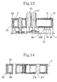
- Fig. 13 is a sectional view corresponding to Fig. 2 but in a condition wherein the tape cassette of a small width type in the embodiment according to the present invention is mounted in the tape producing apparatus body.
- Fig. 14 is a sectional view corresponding to Fig. 5 but showing the tape cassette of a small width type in the embodiment according to the present invention.
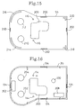
- Fig. 15 is a bottom plan view of a cassette case lid in the embodiment according to the present invention.
- Fig. 16 is a plan view of a cassette case body in the embodiment according to the present invention.
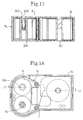
- Fig. 17 shows a tape cassette in the embodiment according to the present invention and is a sectional view taken along a line 17-17 of Fig. 18.
- Fig. 18 shows a tape cassette in the embodiment according to the present invention and is a plan view in a condition wherein a cassette case lid is removed.
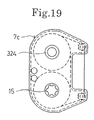
- Fig. 19 is a plan view showing a tape unit in the embodiment according to the present invention.
- Fig. 20 is a bottom plan view of a cassette case lid in a further embodiment according to the present invention.
- Fig. 21 is a plan view of a cassette case body in the embodiment according to the present invention.
- Fig. 1 is a plan view illustrating a condition wherein a tape cassette (in a condition wherein a lid is open) 2 is mounted in a tape producing apparatus body 1;
- Fig. 2 is a sectional view taken along a line II-II of Fig. 1;
- Fig. 3 is a plan view showing the tape producing apparatus body 1 before the tape cassette 2 is mounted;
- Fig. 4 is a sectional view taken along a line IV-IV of Fig. 3;
- Fig. 5 is a sectional view taken along a line V-V of Fig. 1.
- the ribbon unit 7 includes a ribbon holder body 100 including a housing having an elliptical shape as viewed in plan and a pair of arm portions 7a and 7b extending in a predetermined spaced relationship from a side face of the housing, and a ribbon holder lid 92 for covering the ribbon holder body 100.
- a pair of ribbon spools 13 and 15 are provided in the ribbon holder body 100.
- a pair of ribbon guide rollers 17 and 17 are supported for rotation at end portions of the arm portions 7a and 7b, and an exit for an ink ribbon 9 is formed at an end of the arm portion 7a on the ribbon spool 13 side while an entrance for the ink ribbon 9 is formed at an end of the arm portion 7a on the ribbon spool 15 side.
- the ink ribbon 9 is wound on the spool 13 and is partially exposed to the outside of the ribbon holder 100 from the exit under the guidance of the ribbon guide roller 17, enters into the ribbon holder 100 again by way of the entrance, and is wound on the ribbon spool 15 under the guidance of the ribbon guide roller 17.
- the positions in the vertical direction are defined in the proximity of the exit and the entrance by the ribbon guide rollers 17 and 17.
- the ribbon guide roller 17 is mounted through a hole 112 and another hole 110 formed at ends of the arm portions of the ribbon holder body 100 and the ribbon holder lid 92, respectively, and when the ribbon unit 7 is mounted in the cassette case body 3, a shaft 114 extending uprightly from a bottom wall of the cassette case body 3 is fitted into the ribbon guide roller 17 to position the ribbon guide roller 17 while high rigidity is obtained simultaneously.
- the shaft 114 is fitted in and fixed to a hole 116 of a cassette case lid 5.
- a pair of sensor holes 25 and 27 are formed in a bottom wall of the ribbon holder body 100.
- the tape unit 19 includes a tape holder 102 having a U-shaped cross-section, and upper and lower walls of the tape holder 102 are connected to each other via a pair of ribs 102a and 102b.
- a tape 21 wound on a spool 118 is accommodated in the tape holder 102.
- a recessed portion 102c is formed at a portion of the tape holder 102 between the pair of ribs 102a and 102b, and when the tape cassette 2 is mounted in the tape producing apparatus body 1, a platen 47 is inserted into the recessed portion 102c.
- fitting holes 129 for guiding the tape 21 to the outside of the tape unit 19 are formed in the pair of ribs 102a and 102b.
- the spool 118 is mounted in a hole 122 and another hole 124 in the top and the bottom of the tape holder 102, and when the tape unit 19 is mounted in the tape cassette body 3, the spool 118 is fitted onto and positioned by a boss 120 (Fig. 5) of the cassette case body 3.
- the top and the bottom of the tape 21 are guided by a fitting hole 129 in the rib 102b in the proximity of the exit of the tape holder 102. Accordingly, the upward and downward positions of the ink ribbon 9 and the tape 21 are defined by the ribbon unit 7 and the tape unit 19, respectively, and their horizontal positions are defined by the cassette case body 3 and the cassette case lid 5.
- a thermal head 45 is supported for integral pivotal motion with a gear 53 formed integrally therewith on the apparatus body 1 by means of a shaft 51.
- a platen 47, integral with a gear 90, is supported for rotation on a shaft 126 on a lever 49, and the gear 90 is held in mesh with another gear 55 integral with a shaft 69.
- the platen 47 is rotated as rotation of a motor gear 65 is transmitted to the gear 90 by way of gears 63, 61, 59 and 55.
- the motor gear 65 is held in mesh with a ribbon driving gear 37, and rotation of the ribbon driving gear 37 is transmitted to a ribbon driving cam 29 by way of a clutch spring 39 (Fig. 4).
- the clutch spring 39 is anchored at one end of the gear 37 and is freely wrapped around the ribbon driving cam 29 at the other end of the gear.
- the ribbon driving cam 29 and the clutch spring 39 absorb a variation of the winding amount of the ink ribbon 9 and produce torque necessary to take up the ink ribbon 9 when the diameter of the wound ink ribbon 9 varies.
- a gear 57 is secured to the lever 49 and is positioned below the gear 55.
- the gear 57 is rotated counterclockwise while the gear 53 is rotated clockwise so that the platen 47 is moved rightward and the thermal head 45 is moved leftward to put the platen 47 and the thermal head 45 into a separated condition.
- the thermal head 45 and the platen 47 are in a mutually contacting condition by the action of the spring 67.
- Ribbon sensors 71, 73, 75 and tape sensors 71, 73, 75, 77, 79 and 81 are carried on the apparatus body 1, and the type of the ink ribbon 9 and the type of the tape 21 are discriminated from ON/OFF conditions of the sensors.
- the cassette case body 3 is mounted in the apparatus body 1 as shown in Fig. 2, the positions of the cassette case body 3 in the vertical direction are defined by a rib 83 and another rib 85 on the apparatus body 1.
- the ribbon driving cam 29 and the ribbon spool 15 are held in mesh with each other at a projection 29a formed at an upper end of the ribbon driving cam 29 and a portion of a slot 15a formed in the ribbon spool 15 so that rotation is transmitted between them.
- a ribbon supply cam 31 and the ribbon spool 13 are similarly held in mesh with each other.
- a back tension spring 41 is wound on the ribbon supply cam 31 and is fixed to a rib 43 at one end thereof on the apparatus body 1 as shown in Figs. 3 and 4.
- the ribbon unit 7 and the tape unit 19 are accommodated in the cassette case body 3 as shown in Fig. 1.
- the ribbon unit 7 is positioned in the horizontal direction by ribs 136, 138, 140, 142 and 152 on the cassette case body 3, and the tape unit 19 is positioned in the horizontal direction by ribs 144, 146, 148, 150 and 152.
- magnets 134 are provided at four locations on the cassette case body 3, and the cassette case body 3 and the cassette case lid 5 are fixed by iron plates 200 at four locations of the cassette case lid 5 and mounted corresponding to the magnets 134 as shown in Fig. 6. Accordingly, the operator can remove the cassette case lid 5 readily from the cassette case body 3, and the ribbon unit 7 or the tape unit 19 in the cassette case 3 can be replaced readily.
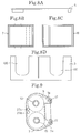
- Recesses 130, 132 are provided at two right and left locations so as to further facilitate replacement of the ribbon unit 7 or the tape unit 19 as shown in Figs. 8A, 8B, 8C and 8D.
- the user can grasp the ribbon unit 7 or the tape unit 19 through the recess 130 or 132.
- Figs. 8A, 8B, 8C and 8D are side elevational views when the ribbon 7 and the tape unit 19 are set to the cassette case body 3 and the cassette case lid 5 is attached. Openings 18, 202, 204, 206 and 208 indicated in Fig. 7 are provided in the cassette case body 3.
- the circular openings 202 and 204 are holes into which the ribbon driving cam 9 and the ribbon supply cam 31 are loosely fitted, and the rectangular openings 206 and 208 are holes corresponding to the ribbon sensor 71, 73, 75 and the tape sensors 77, 79, 81, respectively.
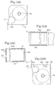
- Fig. 6 shows the bottom wall of the ribbon unit 7, and as shown in Fig. 9, the ribbon unit 7 has a vertically symmetrical profile such that the sensor holes 25 and 27 (shown in Fig.
- each of the ribbon guide rollers 17 presents a through hole as shown in Fig. 5 so that, in whichever vertical direction the ribbon guide roller 17 is mounted onto the cassette case body 3, the shaft 114 of the cassette body 3 is fitted into the through hole. Since the ribbon unit 7 has a vertical symmetrical profile in this manner, it can be mounted either upward or downward. While a one-time ribbon is commonly used on conventional tape producing devices, where the ribbon holder has such a profile as in the present invention, a multi-time ribbon can be mounted and used a plurality of times. As shown in Figs. 1 and 2, the ribbon unit 7 includes the ribbon spools 13 and 15 on which the ink ribbon 9 is wound, the ribbon guide rollers 17, the ribbon holder lid 92 and the ribbon holder 100.
- the ribbon unit 7 includes very few parts and only parts formed of resin without the use of any metal parts. Consequently, parts to be scrapped are very small in number, and separate recovery upon scrapping is very easy.
- Figs. 10A to 10D show the tape unit 19.
- the tape unit 19 includes the tape holder 102 and the tape 21 wound around the spool 118 as described hereinabove.
- the tape holder 102 has a pair of sensor holes 250 and 252 provided on the bottom wall thereof corresponding to the tape sensors 77, 79, 81 of Fig. 3.
- the tape sensor 77 and the tape sensor 79 are in an OFF state while the tape sensor 81 is in an ON state.
- a fitting hole 129 is provided in the rib 102b of the tape unit 19 and defines the vertical position of the tape 21 at the tape exit.
- the tape holder 102 and the spool 118 are made of the same resin material as an ABS resin, and only the two parts remain after the tape 21 is consumed. In this instance, since they are formed of the same parts, they need not be disassembled every time upon separate recovery for scrapping, and recycling of the material is facilitated.
- the tape holder 102 may be formed of paper instead of a resin so that it may be readily disassembled. In this manner, both the tape unit 19 and the ribbon unit 7 include few parts to be scrapped so that separate recovery and recycling of the material can be facilitated.
- the cassette case body 3, the cassette case lid 5, the ribbon holder body 100, the ribbon holder lid 92 and the tape holder 102 are the same as those in the embodiment described above.
- an ink ribbon 9b of a small width is wound at a central portion of the ribbon spool 15 of the ribbon unit 7 as shown in Fig. 11, and a guide portion 17b' is provided on the ribbon guide roller 17b. Accordingly, even if the width of the ink ribbon is different, the vertical position of the ink ribbon is defined.
- Sensor holes are provided in the ribbon holder body 100 such that the ribbon sensor 71 and the ribbon sensor 75 are in an ON state while the ribbon sensor 73 is in an OFF state. Also in the tape unit 19, the tape 21b is wound at a central portion of the spool 118, and a fitting hole 129b of a tape exit is formed narrow in conformity with the width of the tape 21b. Different from the ribbon holder body of the large width type, the sensor holes 250 and 252 are not provided so that all of the tape sensors 77, 79, 81 are in an ON state.
- the ribbon sensors and the tape sensors are discriminated by the ribbon unit 7 and the tape unit 19, respectively, and the positions of the ink ribbon 9 and the tape 21 in the vertical direction are defined by the ribbon unit 7 and the tape unit 19, respectively. Consequently, if the user prepares the single tape cassette 2, the tape 21 and the ink ribbon 9 of any width or any type can be used.
- the size of the tape cassette 2 may be varied in accordance with the width of the tape 21 or the ink ribbon 9 as in the following example.
- a cassette case body 3b and a cassette case lid 5b having small widths are used for the tape 21 and the ink ribbon 9 of the small widths.
- the bottom face of the cassette case body 3b serves as a reference in height to the apparatus body 1 as shown in Fig. 13.
- the cassette case lid 5b has an opening 300 as shown in Fig. 15 so that the thermal head 45 and the platen 47 of Fig. 3 may be inserted into the opening 300. Accordingly, even if the size of the tape cassette 2 is different, it can be discriminated by means of the ribbon sensors 71, 73, 75 and the tape sensors 77, 79, 81.
- the ink ribbon 9 and the tape 21 in the vertical direction are defined by the ribbon unit 7 and the tape unit 19, respectively, when the size of the tape cassette 2 is varied in accordance with the width of the ink ribbon 9 or the tape 21 as in the present example, the ink ribbon 9 and the tape 21 may be positioned in the vertical direction by the cassette case body 3 and the cassette case lid 5. Further, as shown in Fig. 16, the hole 302 of the cassette case body 3b is closed up at a portion corresponding to the hole 27 of the ribbon holder body 100 (Fig. 1), different from the large width cassette case body 3. Consequently, the ribbon sensor 75 (Fig. 3) is always in an ON state, and it is discriminated by the cassette case body 3b that the ink ribbon 9 is of a small width type.
- the ribbon unit 7 is of the vertically reversible type, and back tension to the ink ribbon 9 is applied on a side of the apparatus body 1.
- the ribbon unit need not be the ribbon unit 7 of the vertically reversible type, and back tension to the ink ribbon 9 may be applied from a cassette case body 3c. This will be described below with reference to Figs. 17 to 21.
- a boss 322 is provided on the cassette case body 3c, and a back tension spring 320 is attached to a recessed portion of the boss 322.
- a ribbon spool 324 is brought into such a condition where the back tension spring 320 is flexible.
- the spool 324 does not have such a rib 15a (Fig. 2) as of the ribbon spool 15 and has a cylindrical profile.
- the cassette case 3c is common to that of the embodiment described hereinabove except that the circular opening portion 204 of Fig. 7 is replaced by the boss 322.
- the ribbon unit 7c (Fig. 19) is common to that of the embodiment described above except that the ribbon spool 13 of Fig. 1 is replaced by the spool 324 of Fig. 18.
- Table 1 and Table 2 below illustrate discrimination methods for the ink ribbon 9 and the tape 21, respectively.
- the types of the ink ribbon 9 and the tape 21 employed are discriminated by combinations of ON and OFF states of the sensors 71 to 81.
- the maximum height of characters to be printed and the maximum widthwise printing range are determined based on the ribbon sensors and the tape sensors.
- the user may mount the ribbon unit 7 of a different ribbon width and the tape unit 19 of a different tape width, or the tape units 19 of different widths may be successively replaced and used for the ribbon unit 7 of a single width.
- an error message may be developed when the tape width and the ink ribbon width do not coincide with each other or when the tape width is smaller than the ink ribbon width.
- the compositions of the inks of a tape ribbon and a lettering ribbon are different from each other, the energy to be supplied to the thermal head 45 is different, and non-reverse image printing is performed for a tape while mirror image printing must be performed for a lettering sheet. Therefore, the two ribbons are distinguished from each other.
- an error message is signalled.
- the tape cassette of Fig. 1 in the embodiment described above accommodates a ribbon for a 30 mm tape and a 30 mm tape therein while the tape cassette of Fig. 11 accommodates a ribbon for a 12 mm tape and a 12 mm tape.
- a tape unit 19 for a ribbon for a 30 mm tape and for a 12 mm tape is mounted.
- the tape 21 is offset downwardly from the center of the ink ribbon 9 and corresponds to the range of the lower half of the ink ribbon 9. Accordingly, the ink ribbon 9 is used normally at the lower half thereof.
- the ribbon unit 7 is re-mounted in the cassette case body 3 in a reversed condition. Consequently, printing can be performed further for the length of the ink ribbon 9. Accordingly, when a small width tape is used, a long printing range can be assured with a small capacity.
- the ribbon sensor 75 and the tape sensor 77 discriminate in such a manner as listed in Table 3 below.
- the small width tape is discriminated while Simultaneously the printing range is set only to a lower portion of the thermal head 45. Consequently, a printing range appropriate to a tape position is set.
- TABLE3 PRINTING POSITION CRITERION TABLE No SENSOR 75 SENSOR 77 PRINTING POSITION (RANGE) 1 ON ON entire portion of thermal head 2 ON OFF entire portion of thermal head 3 OFF ON lower portion of thermal head 4 OFF OFF entire portion of thermal head
- the present invention is not limited to the present embodiments and can be applied without departing from the spirit thereof.
- only two widths are described for each of the tape and the ink ribbon in the present embodiments , it is possible to accommodate a plurality of widths.
Abstract
Description
- The present invention relates to a tape cassette for use with a tape producing apparatus, and more particularly, to a tape cassette for exclusively printing on a tape-like printing medium (hereinafter referred to simply as "a tape") using a tape using an ink ribbon.
- A tape cassette for use with a tape producing apparatus of this type is conventionally constructed such that a tape and an ink ribbon having substantially equal widths are accommodated in a corresponding relationship in a single cassette case, and also the lengths of the tape and the ink ribbon are substantially equal to each other. After the tape or the ink ribbon is used up, the entire cassette case is replaced, and the cassette case after use is scrapped. A tape cassette of the type just described is disclosed, for example, in Japanese Utility Model Publication No. Hei 4-32290.
- However, there is room for improvement in the following points in the conventional tape cassette described above.
- As the amount of use of tapes increases, the amount of scrapped cassette cases increases, and consequently, effective use of resources is not achieved, and cinders and smoke produced upon burning of cassette cases damages the environment. If the lengths of the tape and the ink ribbon accommodated in a tape cassette are increased to a great extent, then the amount of the scrapped cassette case per unit length of the tape decreases. However, this raises new problems that the size of the cassette case must be necessarily increased and that also the size of a tape producing apparatus with which the cassette case is used must be increased.
- Further, for a user who wants to use common tapes having different printing colors and/or widths, different cassette cases must be necessarily prepared. This raises such problems that a high cost is required and that a large space is required for accommodation of cassette cases.
- The present invention has been made to solve the problems described above, and it is an object of the present invention to provide a tape cassette, wherein the printing color and/or the printing width can be selected comparatively freely by a user and printing of different colors and/or different sizes can be performed on the same tape.
- In order to attain the object described above, according to the present invention, a tape cassette for use with a tape producing apparatus for exclusively printing on a tape using an ink ribbon is constructed such that the ink ribbon is formed in a unit, and the ink ribbon unit is constructed for replacement from the tape cassette.
- With the tape cassette of the present invention having the construction described above, replacement of the ink ribbon (unit) is easy, and the same tape can be printed using ink ribbons of different colors to accommodate varying user needs. Further, it is also possible to use a multi-time ink ribbon.
- As apparent from the foregoing description, according to a tape cassette of the present invention, a user can replace an ink ribbon freely, and printing can be performed in various colors and with various sizes on the same tape.
- Fig. 1 is a plan view showing a tape cassette in a preferred embodiment according to the present invention in a condition wherein the tape cassette is mounted in an apparatus body with a cassette case lid removed.
- Fig. 2 is a sectional view of the tape cassette, taken along a line II-II of Fig. 1.
- Fig. 3 is a plan view of a tape producing apparatus according to the present invention.
- Fig. 4 is a sectional view of the tape producing apparatus, taken along a line IV-IV of Fig. 3.
- Fig. 5 is a sectional view of the tape cassette, taken along a line V-V of Fig. 1.
- Fig. 6 is a bottom plan view of the cassette case lid.
- Fig. 7 is a plan view of a cassette case body.
- Fig. 8A is a side elevational view of a tape cassette lid.
- Fig. 8B is a side elevational view of a ribbon unit.
- Fig. 8C is a side elevational view of a tape unit.
- Fig. 8D is a side elevational view of a cassette case body.
- Fig. 9 is a bottom plan view of the ink ribbon unit.
- Fig. 10A shows a plan view of a tape unit.
- Fig. 10B is a front elevational view of a tape unit.
- Fig. 10C is a side elevational view of a tape unit.
- Fig. 10D is a bottom plan view of a tape unit.
- Fig. 11 is a sectional view corresponding to Fig. 5 but illustrating a condition in which an ink ribbon unit and a tape unit of a small width type in another embodiment according to the present invention are mounted.
- Fig. 12A is a side elevational view of a tape cassette lid of a small width type.
- Fig. 12B is a side elevational view of a ribbon unit of a small width type.
- Fig. 12C is a side elevational view of a tape unit of a small width type.
- Fig. 12D is a side elevational view of a cassette case body of a small width type.
- Fig. 13 is a sectional view corresponding to Fig. 2 but in a condition wherein the tape cassette of a small width type in the embodiment according to the present invention is mounted in the tape producing apparatus body.
- Fig. 14 is a sectional view corresponding to Fig. 5 but showing the tape cassette of a small width type in the embodiment according to the present invention.
- Fig. 15 is a bottom plan view of a cassette case lid in the embodiment according to the present invention.
- Fig. 16 is a plan view of a cassette case body in the embodiment according to the present invention.
- Fig. 17 shows a tape cassette in the embodiment according to the present invention and is a sectional view taken along a line 17-17 of Fig. 18.
- Fig. 18 shows a tape cassette in the embodiment according to the present invention and is a plan view in a condition wherein a cassette case lid is removed.
- Fig. 19 is a plan view showing a tape unit in the embodiment according to the present invention.
- Fig. 20 is a bottom plan view of a cassette case lid in a further embodiment according to the present invention.
- Fig. 21 is a plan view of a cassette case body in the embodiment according to the present invention.
- In the following, a tape cassette in an embodiment according to the present invention will be described with reference to the drawings.
- Fig. 1 is a plan view illustrating a condition wherein a tape cassette (in a condition wherein a lid is open) 2 is mounted in a tape producing
apparatus body 1; Fig. 2 is a sectional view taken along a line II-II of Fig. 1; Fig. 3 is a plan view showing the tape producingapparatus body 1 before thetape cassette 2 is mounted; Fig. 4 is a sectional view taken along a line IV-IV of Fig. 3; and Fig. 5 is a sectional view taken along a line V-V of Fig. 1. - As shown in Figs. 1, 2 and 9, a
ribbon unit 7 and atape unit 19 are accommodated for individual replacement in acassette case body 3 of the tape cassette (cassette case) 2. Theribbon unit 7 includes aribbon holder body 100 including a housing having an elliptical shape as viewed in plan and a pair ofarm portions ribbon holder lid 92 for covering theribbon holder body 100. A pair ofribbon spools ribbon holder body 100. A pair ofribbon guide rollers arm portions ink ribbon 9 is formed at an end of thearm portion 7a on theribbon spool 13 side while an entrance for theink ribbon 9 is formed at an end of thearm portion 7a on theribbon spool 15 side. Theink ribbon 9 is wound on thespool 13 and is partially exposed to the outside of theribbon holder 100 from the exit under the guidance of theribbon guide roller 17, enters into theribbon holder 100 again by way of the entrance, and is wound on theribbon spool 15 under the guidance of theribbon guide roller 17. The positions in the vertical direction are defined in the proximity of the exit and the entrance by theribbon guide rollers - As shown in Fig. 5, the
ribbon guide roller 17 is mounted through ahole 112 and anotherhole 110 formed at ends of the arm portions of theribbon holder body 100 and theribbon holder lid 92, respectively, and when theribbon unit 7 is mounted in thecassette case body 3, ashaft 114 extending uprightly from a bottom wall of thecassette case body 3 is fitted into theribbon guide roller 17 to position theribbon guide roller 17 while high rigidity is obtained simultaneously. Theshaft 114 is fitted in and fixed to ahole 116 of acassette case lid 5. Further, as shown in Fig. 2, a pair of sensor holes 25 and 27 are formed in a bottom wall of theribbon holder body 100. - As shown in Figs. 5, 10A, 10B, 10C and 10D, the
tape unit 19 includes atape holder 102 having a U-shaped cross-section, and upper and lower walls of thetape holder 102 are connected to each other via a pair ofribs tape 21 wound on aspool 118 is accommodated in thetape holder 102. A recessedportion 102c is formed at a portion of thetape holder 102 between the pair ofribs tape cassette 2 is mounted in the tape producingapparatus body 1, aplaten 47 is inserted into the recessedportion 102c. Further,fitting holes 129 for guiding thetape 21 to the outside of thetape unit 19 are formed in the pair ofribs spool 118 is mounted in ahole 122 and anotherhole 124 in the top and the bottom of thetape holder 102, and when thetape unit 19 is mounted in thetape cassette body 3, thespool 118 is fitted onto and positioned by a boss 120 (Fig. 5) of thecassette case body 3. The top and the bottom of thetape 21 are guided by afitting hole 129 in therib 102b in the proximity of the exit of thetape holder 102. Accordingly, the upward and downward positions of theink ribbon 9 and thetape 21 are defined by theribbon unit 7 and thetape unit 19, respectively, and their horizontal positions are defined by thecassette case body 3 and thecassette case lid 5. - The structure and operation of the tape producing
apparatus body 1 will be described. As shown in Figs. 2 and 3, athermal head 45 is supported for integral pivotal motion with agear 53 formed integrally therewith on theapparatus body 1 by means of ashaft 51. Aplaten 47, integral with agear 90, is supported for rotation on ashaft 126 on alever 49, and thegear 90 is held in mesh with anothergear 55 integral with ashaft 69. Theplaten 47 is rotated as rotation of amotor gear 65 is transmitted to thegear 90 by way ofgears motor gear 65 is held in mesh with aribbon driving gear 37, and rotation of theribbon driving gear 37 is transmitted to aribbon driving cam 29 by way of a clutch spring 39 (Fig. 4). As shown in Fig. 4, theclutch spring 39 is anchored at one end of thegear 37 and is freely wrapped around theribbon driving cam 29 at the other end of the gear. Theribbon driving cam 29 and theclutch spring 39 absorb a variation of the winding amount of theink ribbon 9 and produce torque necessary to take up theink ribbon 9 when the diameter of thewound ink ribbon 9 varies. - A
gear 57 is secured to thelever 49 and is positioned below thegear 55. When thelever 49 is operated leftward from the position shown in Fig. 3 against aspring 67, thegear 57 is rotated counterclockwise while thegear 53 is rotated clockwise so that theplaten 47 is moved rightward and thethermal head 45 is moved leftward to put theplaten 47 and thethermal head 45 into a separated condition. In the condition shown in Fig. 3, thethermal head 45 and theplaten 47 are in a mutually contacting condition by the action of thespring 67. When thecassette case body 3 is mounted in theapparatus body 1, thethermal head 45 and theplaten 47 are inserted into anopening 18 of thecassette case body 3 while thethermal head 45 and theplaten 47 are in a spaced condition from each other. In this instance, since theink ribbon 9 and thetape 21 are in the positions indicated by a two-dot chain line in Fig. 1, they will not interfere with thethermal head 45 nor theplaten 47. -
Ribbon sensors tape sensors apparatus body 1, and the type of theink ribbon 9 and the type of thetape 21 are discriminated from ON/OFF conditions of the sensors. When thecassette case body 3 is mounted in theapparatus body 1 as shown in Fig. 2, the positions of thecassette case body 3 in the vertical direction are defined by arib 83 and anotherrib 85 on theapparatus body 1. Further, theribbon driving cam 29 and theribbon spool 15 are held in mesh with each other at aprojection 29a formed at an upper end of theribbon driving cam 29 and a portion of aslot 15a formed in theribbon spool 15 so that rotation is transmitted between them. Aribbon supply cam 31 and theribbon spool 13 are similarly held in mesh with each other. Aback tension spring 41 is wound on theribbon supply cam 31 and is fixed to arib 43 at one end thereof on theapparatus body 1 as shown in Figs. 3 and 4. When theink ribbon 9 is rotated clockwise in the condition of Fig. 1, tension is applied to theink ribbon 9 by friction force between theribbon supply cam 31 and theback tension spring 41. - The
tape cassette 2 will now be described in more detail. As described hereinabove, theribbon unit 7 and thetape unit 19 are accommodated in thecassette case body 3 as shown in Fig. 1. Theribbon unit 7 is positioned in the horizontal direction byribs cassette case body 3, and thetape unit 19 is positioned in the horizontal direction byribs magnets 134 are provided at four locations on thecassette case body 3, and thecassette case body 3 and thecassette case lid 5 are fixed byiron plates 200 at four locations of thecassette case lid 5 and mounted corresponding to themagnets 134 as shown in Fig. 6. Accordingly, the operator can remove thecassette case lid 5 readily from thecassette case body 3, and theribbon unit 7 or thetape unit 19 in thecassette case 3 can be replaced readily. -
Recesses ribbon unit 7 or thetape unit 19 as shown in Figs. 8A, 8B, 8C and 8D. The user can grasp theribbon unit 7 or thetape unit 19 through therecess ribbon 7 and thetape unit 19 are set to thecassette case body 3 and thecassette case lid 5 is attached.Openings cassette case body 3. Thecircular openings ribbon driving cam 9 and theribbon supply cam 31 are loosely fitted, and therectangular openings ribbon sensor tape sensors - As shown in Fig. 6,
circular openings ribbon driving cam 29 and theribbon supply cam 31 are provided in thecassette case lid 5 similarly to in thecassette case body 3. Further, a pair ofholes 116 of a small diameter are holes into which theshafts 114 of thecassette case body 3 are fitted. As described above, theiron plates 200 corresponding to themagnets 134 are provided at four locations, and positioningribs cassette case body 3 are provided projectingly at corner portions. Fig. 9 shows the bottom wall of theribbon unit 7, and as shown in Fig. 9, theribbon unit 7 has a vertically symmetrical profile such that the sensor holes 25 and 27 (shown in Fig. 1) in the upper wall of theribbon unit 7 and the sensor holes 25b and 27b in the bottom wall are provided at locations that are symmetrical with respect to a longitudinal center line of theribbon unit 7 so that, even if theribbon unit 7 is mounted upside down, it can be detected similarly by theribbon sensors - A central portion of each of the
ribbon guide rollers 17 presents a through hole as shown in Fig. 5 so that, in whichever vertical direction theribbon guide roller 17 is mounted onto thecassette case body 3, theshaft 114 of thecassette body 3 is fitted into the through hole. Since theribbon unit 7 has a vertical symmetrical profile in this manner, it can be mounted either upward or downward. While a one-time ribbon is commonly used on conventional tape producing devices, where the ribbon holder has such a profile as in the present invention, a multi-time ribbon can be mounted and used a plurality of times. As shown in Figs. 1 and 2, theribbon unit 7 includes the ribbon spools 13 and 15 on which theink ribbon 9 is wound, theribbon guide rollers 17, theribbon holder lid 92 and theribbon holder 100. Springs such as the ribbon back tension spring 41 (Figs. 3 and 4) are installed on theapparatus body 1 side. Accordingly, theribbon unit 7 includes very few parts and only parts formed of resin without the use of any metal parts. Consequently, parts to be scrapped are very small in number, and separate recovery upon scrapping is very easy. - Figs. 10A to 10D show the
tape unit 19. Thetape unit 19 includes thetape holder 102 and thetape 21 wound around thespool 118 as described hereinabove. Thetape holder 102 has a pair ofsensor holes tape sensors present tape unit 19, thetape sensor 77 and thetape sensor 79 are in an OFF state while thetape sensor 81 is in an ON state. Afitting hole 129 is provided in therib 102b of thetape unit 19 and defines the vertical position of thetape 21 at the tape exit. Thetape holder 102 and thespool 118 are made of the same resin material as an ABS resin, and only the two parts remain after thetape 21 is consumed. In this instance, since they are formed of the same parts, they need not be disassembled every time upon separate recovery for scrapping, and recycling of the material is facilitated. Alternatively, thetape holder 102 may be formed of paper instead of a resin so that it may be readily disassembled. In this manner, both thetape unit 19 and theribbon unit 7 include few parts to be scrapped so that separate recovery and recycling of the material can be facilitated. - While the
tape 21 and theink ribbon 9 of the large width type are described so far, those of a small width type will now be described with reference to Figs. 11 and 12. Thecassette case body 3, thecassette case lid 5, theribbon holder body 100, theribbon holder lid 92 and thetape holder 102 are the same as those in the embodiment described above. First, anink ribbon 9b of a small width is wound at a central portion of theribbon spool 15 of theribbon unit 7 as shown in Fig. 11, and aguide portion 17b' is provided on theribbon guide roller 17b. Accordingly, even if the width of the ink ribbon is different, the vertical position of the ink ribbon is defined. - Sensor holes (not shown), different from those of the embodiment described above, are provided in the
ribbon holder body 100 such that theribbon sensor 71 and theribbon sensor 75 are in an ON state while theribbon sensor 73 is in an OFF state. Also in thetape unit 19, thetape 21b is wound at a central portion of thespool 118, and afitting hole 129b of a tape exit is formed narrow in conformity with the width of thetape 21b. Different from the ribbon holder body of the large width type, the sensor holes 250 and 252 are not provided so that all of thetape sensors ribbon unit 7 and thetape unit 19, respectively, and the positions of theink ribbon 9 and thetape 21 in the vertical direction are defined by theribbon unit 7 and thetape unit 19, respectively. Consequently, if the user prepares thesingle tape cassette 2, thetape 21 and theink ribbon 9 of any width or any type can be used. - While in the present embodiment the same
cassette case body 3 and the samecassette case lid 5 are used irrespective of the width of thetape 21 or theink ribbon 9, the size of thetape cassette 2 may be varied in accordance with the width of thetape 21 or theink ribbon 9 as in the following example. As shown in Fig. 14, for thetape 21 and theink ribbon 9 of the small widths, acassette case body 3b and acassette case lid 5b having small widths are used. In this instance, the bottom face of thecassette case body 3b serves as a reference in height to theapparatus body 1 as shown in Fig. 13. Thecassette case lid 5b has anopening 300 as shown in Fig. 15 so that thethermal head 45 and theplaten 47 of Fig. 3 may be inserted into theopening 300. Accordingly, even if the size of thetape cassette 2 is different, it can be discriminated by means of theribbon sensors tape sensors - While the positions of the
ink ribbon 9 and thetape 21 in the vertical direction are defined by theribbon unit 7 and thetape unit 19, respectively, when the size of thetape cassette 2 is varied in accordance with the width of theink ribbon 9 or thetape 21 as in the present example, theink ribbon 9 and thetape 21 may be positioned in the vertical direction by thecassette case body 3 and thecassette case lid 5. Further, as shown in Fig. 16, thehole 302 of thecassette case body 3b is closed up at a portion corresponding to the hole 27 of the ribbon holder body 100 (Fig. 1), different from the large widthcassette case body 3. Consequently, the ribbon sensor 75 (Fig. 3) is always in an ON state, and it is discriminated by thecassette case body 3b that theink ribbon 9 is of a small width type. - In the embodiment described above, the
ribbon unit 7 is of the vertically reversible type, and back tension to theink ribbon 9 is applied on a side of theapparatus body 1. However, where a one-time ink ribbon 9' is used, the ribbon unit need not be theribbon unit 7 of the vertically reversible type, and back tension to theink ribbon 9 may be applied from acassette case body 3c. This will be described below with reference to Figs. 17 to 21. - As shown in Fig. 17, a
boss 322 is provided on thecassette case body 3c, and aback tension spring 320 is attached to a recessed portion of theboss 322. When aribbon unit 7c is mounted in thecassette case body 3c, aribbon spool 324 is brought into such a condition where theback tension spring 320 is flexible. By the spring force, friction force is produced between theboss 322 and thespool 324 so that back tension is applied to theink ribbon 9. Thespool 324 does not have such arib 15a (Fig. 2) as of theribbon spool 15 and has a cylindrical profile. As shown in Figs. 20 and 21, theopening hole 210 of Fig. 6 is not provided in thecassette case lid 5c, and thecassette case 3c is common to that of the embodiment described hereinabove except that thecircular opening portion 204 of Fig. 7 is replaced by theboss 322. Further, theribbon unit 7c (Fig. 19) is common to that of the embodiment described above except that theribbon spool 13 of Fig. 1 is replaced by thespool 324 of Fig. 18. - Discrimination methods of the ribbon sensors and the tape sensors will be described. Table 1 and Table 2 below illustrate discrimination methods for the
ink ribbon 9 and thetape 21, respectively. The types of theink ribbon 9 and thetape 21 employed are discriminated by combinations of ON and OFF states of thesensors 71 to 81. The maximum height of characters to be printed and the maximum widthwise printing range are determined based on the ribbon sensors and the tape sensors. In short, the user may mount theribbon unit 7 of a different ribbon width and thetape unit 19 of a different tape width, or thetape units 19 of different widths may be successively replaced and used for theribbon unit 7 of a single width. In those instances, if the printing range is not adjusted to a smaller one of the widths of thetape 21 and theribbon 9, then characters protrude from the tape width or the width of the ribbon is so small that characters are cut. Therefore, information of both of the ribbon sensors and the tape sensors is used so that the printing range may be set in conformity with a smaller one of the widths. - Alternatively, an error message may be developed when the tape width and the ink ribbon width do not coincide with each other or when the tape width is smaller than the ink ribbon width.
- Since the compositions of the inks of a tape ribbon and a lettering ribbon are different from each other, the energy to be supplied to the
thermal head 45 is different, and non-reverse image printing is performed for a tape while mirror image printing must be performed for a lettering sheet. Therefore, the two ribbons are distinguished from each other. When the combination of a tape ribbon and a tape or the combination of a lettering ribbon and a lettering sheet is not assured correctly, an error message is signalled. For example, the tape cassette of Fig. 1 in the embodiment described above accommodates a ribbon for a 30 mm tape and a 30 mm tape therein while the tape cassette of Fig. 11 accommodates a ribbon for a 12 mm tape and a 12 mm tape.TABLE1 RIBBON SENSOR CRITERION TABLE No SENSOR 71 SENSOR 73SENSOR 75CRITERION CONTENT 1 ON ON ON 12mm lettering ribbon 2 ON OFF ON 12mm tape ribbon 3 ON ON OFF 30mm lettering ribbon 4 ON OFF OFF 30mm tape ribbon 5 OFF OFF ON 12mm cassette, no ribbon 6 OFF OFF OFF 30mm cassette, no ribbon TABLE2 TAPE SENSOR CRITERION TABLE No SENSOR 77 SENSOR 79SENSOR 81CRITERION CONTENT 1 ON ON ON 12mm tape 2 ON OFF ON 12mm lettering sheet 3 OFF OFF ON 30mm tape 4 OFF ON ON 30mm lettering sheet 5 OFF OFF OFF no tape - The following examples may be available in addition to the examples described so far. As shown in Fig. 11, a
tape unit 19 for a ribbon for a 30 mm tape and for a 12 mm tape is mounted. Thetape 21 is offset downwardly from the center of theink ribbon 9 and corresponds to the range of the lower half of theink ribbon 9. Accordingly, theink ribbon 9 is used normally at the lower half thereof. After theink ribbon 9 is used up, theribbon unit 7 is re-mounted in thecassette case body 3 in a reversed condition. Consequently, printing can be performed further for the length of theink ribbon 9. Accordingly, when a small width tape is used, a long printing range can be assured with a small capacity. In this instance, theribbon sensor 75 and thetape sensor 77 discriminate in such a manner as listed in Table 3 below. In short, when an ink ribbon of a large width and a tape of a small width are mounted, the small width tape is discriminated while Simultaneously the printing range is set only to a lower portion of thethermal head 45. Consequently, a printing range appropriate to a tape position is set.TABLE3 PRINTING POSITION CRITERION TABLE No SENSOR 75 SENSOR 77PRINTING POSITION (RANGE) 1 ON ON entire portion of thermal head 2 ON OFF entire portion of thermal head 3 OFF ON lower portion of thermal head 4 OFF OFF entire portion of thermal head - The present invention is not limited to the present embodiments and can be applied without departing from the spirit thereof. For example, while only two widths are described for each of the tape and the ink ribbon in the present embodiments, it is possible to accommodate a plurality of widths.
Claims (14)
- A tape cassette in a tape printing apparatus for printing on a tape using an ink ribbon, the tape cassette comprising:
a ribbon unit housing said ink ribbon, said ribbon unit being separately removable from said tape cassette; and
a tape unit housing said tape, said tape unit being separately removable from said tape cassette. - The tape cassette according to claim 1, wherein said ribbon unit comprises a ribbon supply cam engaging said ink ribbon, and a tension spring wound on said ribbon supply cam, said tension spring applying tension to said ink ribbon when said ink ribbon is rotated.
- The tape cassette according to claim 1 or 2, wherein said ribbon unit comprises a vertically symmetrical profile such that it can be inserted in said tape cassette in at least two orientations.
- The tape cassette according to one of claims 1 to 3, wherein a width of said tape is about one-half the width of said ink ribbon.
- The tape cassette according to one of claims 1 to 4, comprising discriminating means for indicating an ink ribbon type of said ribbon unit and for indicating a tape type of said tape, or wherein said ink ribbon unit comprises first discriminating means for indicating an ink ribbon type of said ink ribbon and said tape unit comprises second discriminating means for indicating a tape type of said tape.
- The tape cassette according to one of claims 1 to 5, wherein said ribbon unit and said tape unit are manufactured from the same material, preferably a resin material or paper, or wherein at least one of said ribbon unit and said tape unit is manufactured from a single material.
- The tape cassette according to one of claims 1 to 6, wherein said ink ribbon is a multi-use ink ribbon.
- The tape cassette according to one of claims 1 to 7, further comprising a cassette case body, said cassette case body shaped to removably receive said ribbon unit and said tape unit.
- The tape cassette according to claim 8, wherein a position of said cassette case body in said tape cassette in a transverse direction of said tape is defined by a pair of ribs protruding from said tape cassette.
- The tape cassette according to claim 8 or 9, further comprising a cassette case lid for closing said cassette case body, wherein at least one magnet is fixed to one of said cassette case body and said cassette case lid, and a corresponding at least one metal plate is fixed to the other of said cassette case body and said cassette case lid for engaging said at least one magnet.
- The tape cassette according to one of claims 8 to 10, wherein said cassette case body further comprises at least one recess providing access to a corresponding at least one of said ribbon unit and said tape unit.
- The tape cassette according to one of claims 5 to 11, further comprising means for setting a printing range in accordance with an indication from said discriminating means.
- The tape cassette according to one of claims 5 to 12, further comprising means for generating an error signal if a ribbon type indicated by said discriminating means and a tape type indicated by said discriminating means are incompatible.
- The tape cassette according to one of claims 5 to 13, wherein said discriminating means comprises at least one sensor fixed to said tape cassette, said at least one sensor determining at least one of said ribbon type of said ribbon and said tape type of said tape.
Applications Claiming Priority (2)
| Application Number | Priority Date | Filing Date | Title |
|---|---|---|---|
| JP141424/93 | 1993-05-19 | ||
| JP5141424A JPH06328821A (en) | 1993-05-19 | 1993-05-19 | Tape cassette |
Publications (2)
| Publication Number | Publication Date |
|---|---|
| EP0625427A2 true EP0625427A2 (en) | 1994-11-23 |
| EP0625427A3 EP0625427A3 (en) | 1995-07-12 |
Family
ID=15291674
Family Applications (1)
| Application Number | Title | Priority Date | Filing Date |
|---|---|---|---|
| EP94103943A Withdrawn EP0625427A3 (en) | 1993-05-19 | 1994-03-14 | Tape cassette. |
Country Status (3)
| Country | Link |
|---|---|
| US (1) | US5454650A (en) |
| EP (1) | EP0625427A3 (en) |
| JP (1) | JPH06328821A (en) |
Cited By (15)
| Publication number | Priority date | Publication date | Assignee | Title |
|---|---|---|---|---|
| EP0629509A2 (en) * | 1993-06-15 | 1994-12-21 | Brother Kogyo Kabushiki Kaisha | Tape cassette |
| EP0734871A2 (en) * | 1995-03-29 | 1996-10-02 | Brother Kogyo Kabushiki Kaisha | Tape-shaped label printing device |
| EP0734878A2 (en) * | 1995-03-29 | 1996-10-02 | Brother Kogyo Kabushiki Kaisha | A composite cassette including a tape cassette and a ribbon cassette |
| EP0734879A2 (en) * | 1995-03-29 | 1996-10-02 | Brother Kogyo Kabushiki Kaisha | A printer and a composite cassette including a tape cassette and a ribbon cassette used in the printer |
| EP0773110A2 (en) * | 1995-11-10 | 1997-05-14 | Esselte N.V. | Set of tape cartridges and printing apparatus |
| EP0787591A1 (en) * | 1996-01-31 | 1997-08-06 | Brother Kogyo Kabushiki Kaisha | Tape-shaped label printing device |
| EP0704311A3 (en) * | 1994-09-28 | 1998-04-01 | Brother Kogyo Kabushiki Kaisha | Cassette for printed tape and method of printing |
| EP0769386B1 (en) * | 1995-10-19 | 1999-03-17 | Brother Kogyo Kabushiki Kaisha | Tape-shaped label printing device |
| US6006014A (en) * | 1995-10-19 | 1999-12-21 | Brother Kogyo Kabushiki Kaisha | Tape-shaped label printing device having color range setting means |
| US6132120A (en) * | 1995-03-29 | 2000-10-17 | Brother Kogyo Kabushiki Kaisha | Tape-shaped label printing device |
| EP1106367A1 (en) * | 1995-11-10 | 2001-06-13 | Esselte N.V. | Set of tape cartridges and printing apparatus |
| EP1176026A1 (en) * | 1996-03-13 | 2002-01-30 | Esselte N.V. | Tape printing apparatus and tape holding case |
| CN1085151C (en) * | 1995-03-29 | 2002-05-22 | 兄弟工业株式会社 | Combined box containing a paper-tape box and a colour-tape box |
| WO2005100034A1 (en) | 2004-04-16 | 2005-10-27 | Ecobags S.R.L. | Thermal transfer printer/labeller specifically designed for cassettes or ready-to-use packages |
| WO2010125128A1 (en) * | 2009-04-28 | 2010-11-04 | Dymo | Sub-assemblies for use in a casette |
Families Citing this family (22)
| Publication number | Priority date | Publication date | Assignee | Title |
|---|---|---|---|---|
| US6042280A (en) * | 1995-05-25 | 2000-03-28 | Brother Kogyo Kabushiki Kaisha | Tape label printing device |
| US6196740B1 (en) | 1994-05-25 | 2001-03-06 | Brother Kogyo Kabushiki Kaisha | Tape-shaped label printing device |
| JP3111445B2 (en) * | 1995-03-29 | 2000-11-20 | ブラザー工業株式会社 | Tape-shaped label making device |
| US6190069B1 (en) | 1994-05-25 | 2001-02-20 | Brother Kogyo Kabushiki Kaisha | Tape-shaped label printing device |
| EP0794066B1 (en) * | 1996-03-07 | 2000-05-17 | Esselte N.V. | Means to detect a ribbon cassette in a tape printing apparatus |
| USD423566S (en) * | 1998-07-14 | 2000-04-25 | Olympus Optical Co., Ltd. | Cartridge for a label printer |
| MX2007006388A (en) | 2004-11-30 | 2007-06-20 | Panduit Corp | Market-based labeling system and method. |
| US9061522B2 (en) * | 2005-03-16 | 2015-06-23 | Panduit Corp. | Reversible printer assembly |
| PT2666642E (en) | 2008-12-25 | 2016-02-10 | Brother Ind Ltd | Tape cassette and tape printer |
| KR20150038644A (en) | 2008-12-25 | 2015-04-08 | 브라더 고오교오 가부시키가이샤 | Tape cassette |
| CN104589815B (en) | 2009-03-31 | 2017-04-12 | 兄弟工业株式会社 | Tape cassette and tape printer |
| WO2010113780A1 (en) | 2009-03-31 | 2010-10-07 | ブラザー工業株式会社 | Tape cassette |
| JP5267292B2 (en) * | 2009-04-10 | 2013-08-21 | ブラザー工業株式会社 | Printing device |
| EP2448762B1 (en) | 2009-06-30 | 2013-09-18 | Brother Kogyo Kabushiki Kaisha | Tape cassette and tape printer |
| CN102510806B (en) | 2009-12-16 | 2014-06-18 | 兄弟工业株式会社 | Tape cassette |
| WO2011080840A1 (en) * | 2009-12-28 | 2011-07-07 | ブラザー工業株式会社 | Tape cassette |
| JP6144221B2 (en) * | 2014-03-24 | 2017-06-07 | セイコーエプソン株式会社 | Tape cartridge |
| US11220582B2 (en) | 2017-03-03 | 2022-01-11 | Harland Medical Systems, Inc. | Coating composition comprised of a hydrophilic crosslinker, a hydrophobic crosslinker and optionally a hydrogel and methods of making and using the same |
| US10875048B2 (en) | 2017-09-05 | 2020-12-29 | Harland Medical Systems, Inc | Coating apparatus with an automatic fluid level system, and methods of using the same |
| JP7287840B2 (en) * | 2019-06-19 | 2023-06-06 | セイコーエプソン株式会社 | Container and tape printing system |
| US11241896B2 (en) * | 2019-06-19 | 2022-02-08 | Seiko Epson Corporation | Housing case and tape ribbon set |
| JP2021000814A (en) * | 2019-06-19 | 2021-01-07 | セイコーエプソン株式会社 | Storage body and tape ribbon set |
Citations (5)
| Publication number | Priority date | Publication date | Assignee | Title |
|---|---|---|---|---|
| GB2161754A (en) * | 1984-07-18 | 1986-01-22 | K Sun Corp | Two-piece tape/ribbon cartridge |
| US5028934A (en) * | 1988-10-31 | 1991-07-02 | Seiko Epson Corporation | Hand-held portable printing system |
| US5111216A (en) * | 1988-07-12 | 1992-05-05 | Kroy Inc. | Tape supply cartridge for portable thermal printer |
| US5193919A (en) * | 1989-11-09 | 1993-03-16 | Seiko Epson Corporation | Tape printer |
| EP0573187A1 (en) * | 1992-06-01 | 1993-12-08 | Esselte Dymo N.V. | Thermal printing device |
Family Cites Families (10)
| Publication number | Priority date | Publication date | Assignee | Title |
|---|---|---|---|---|
| US4367963A (en) * | 1980-07-21 | 1983-01-11 | Wordex | Refillable typewriter ribbon cartridge |
| US4480936A (en) * | 1983-01-24 | 1984-11-06 | K-Sun Corporation | Two-piece tape/ribbon cartridge |
| US4970531A (en) * | 1987-02-13 | 1990-11-13 | Hitachi, Ltd. | Thermal transfer printer |
| US5087137A (en) * | 1988-07-19 | 1992-02-11 | Datamax Corporation | Ribbon assembly including indicia to identify operating parameters and ribbon depletion |
| WO1990001434A1 (en) * | 1988-07-29 | 1990-02-22 | Jin Shimojo | Inside rearview mirror |
| JPH0432290A (en) * | 1990-05-29 | 1992-02-04 | Aichi Electric Co Ltd | Solid wiring circuit board |
| US5248207A (en) * | 1990-08-27 | 1993-09-28 | Minolta Camera Kabushiki Kaisha | Thermal printer provided with detachable head unit having built-in thermal head unit |
| JP3166206B2 (en) * | 1990-08-29 | 2001-05-14 | セイコーエプソン株式会社 | Tape printer and control method thereof |
| US5284396A (en) * | 1991-07-29 | 1994-02-08 | Kanzaki Paper Mfg. Co., Ltd. | Ribbon feeder for a printer having a tension mechanism |
| GB9211544D0 (en) * | 1992-06-01 | 1992-07-15 | Esselte Dymo Nv | Label printing apparatus |
-
1993
- 1993-05-19 JP JP5141424A patent/JPH06328821A/en active Pending
-
1994
- 1994-02-23 US US08/200,709 patent/US5454650A/en not_active Expired - Lifetime
- 1994-03-14 EP EP94103943A patent/EP0625427A3/en not_active Withdrawn
Patent Citations (5)
| Publication number | Priority date | Publication date | Assignee | Title |
|---|---|---|---|---|
| GB2161754A (en) * | 1984-07-18 | 1986-01-22 | K Sun Corp | Two-piece tape/ribbon cartridge |
| US5111216A (en) * | 1988-07-12 | 1992-05-05 | Kroy Inc. | Tape supply cartridge for portable thermal printer |
| US5028934A (en) * | 1988-10-31 | 1991-07-02 | Seiko Epson Corporation | Hand-held portable printing system |
| US5193919A (en) * | 1989-11-09 | 1993-03-16 | Seiko Epson Corporation | Tape printer |
| EP0573187A1 (en) * | 1992-06-01 | 1993-12-08 | Esselte Dymo N.V. | Thermal printing device |
Cited By (23)
| Publication number | Priority date | Publication date | Assignee | Title |
|---|---|---|---|---|
| EP0629509A2 (en) * | 1993-06-15 | 1994-12-21 | Brother Kogyo Kabushiki Kaisha | Tape cassette |
| EP0629509A3 (en) * | 1993-06-15 | 1995-07-05 | Brother Ind Ltd | Tape cassette. |
| US5492282A (en) * | 1993-06-15 | 1996-02-20 | Brother Kogyo Kabushiki Kaisha | Refillable tape cassettes of varying thicknesses with unique spool mounting structures |
| EP0704311A3 (en) * | 1994-09-28 | 1998-04-01 | Brother Kogyo Kabushiki Kaisha | Cassette for printed tape and method of printing |
| EP0734871A3 (en) * | 1995-03-29 | 1997-05-07 | Brother Ind Ltd | Tape-shaped label printing device |
| EP0734879A2 (en) * | 1995-03-29 | 1996-10-02 | Brother Kogyo Kabushiki Kaisha | A printer and a composite cassette including a tape cassette and a ribbon cassette used in the printer |
| EP0734878A2 (en) * | 1995-03-29 | 1996-10-02 | Brother Kogyo Kabushiki Kaisha | A composite cassette including a tape cassette and a ribbon cassette |
| CN1085151C (en) * | 1995-03-29 | 2002-05-22 | 兄弟工业株式会社 | Combined box containing a paper-tape box and a colour-tape box |
| EP0734878A3 (en) * | 1995-03-29 | 1997-05-14 | Brother Ind Ltd | A composite cassette including a tape cassette and a ribbon cassette |
| EP0734879A3 (en) * | 1995-03-29 | 1997-05-21 | Brother Ind Ltd | A printer and a composite cassette including a tape cassette and a ribbon cassette used in the printer |
| US6132120A (en) * | 1995-03-29 | 2000-10-17 | Brother Kogyo Kabushiki Kaisha | Tape-shaped label printing device |
| US5727888A (en) * | 1995-03-29 | 1998-03-17 | Brother Kogyo Kabushiki Kaisha | Printer and a composite cassette including a tape cassette and a ribbon cassette used in the printer |
| EP0734871A2 (en) * | 1995-03-29 | 1996-10-02 | Brother Kogyo Kabushiki Kaisha | Tape-shaped label printing device |
| EP0769386B1 (en) * | 1995-10-19 | 1999-03-17 | Brother Kogyo Kabushiki Kaisha | Tape-shaped label printing device |
| US6006014A (en) * | 1995-10-19 | 1999-12-21 | Brother Kogyo Kabushiki Kaisha | Tape-shaped label printing device having color range setting means |
| US5857788A (en) * | 1995-11-10 | 1999-01-12 | Esselte Nv | Thermal printing device with direct thermal cassette |
| EP0773110A3 (en) * | 1995-11-10 | 1998-08-26 | Esselte N.V. | Set of tape cartridges and printing apparatus |
| EP1106367A1 (en) * | 1995-11-10 | 2001-06-13 | Esselte N.V. | Set of tape cartridges and printing apparatus |
| EP0773110A2 (en) * | 1995-11-10 | 1997-05-14 | Esselte N.V. | Set of tape cartridges and printing apparatus |
| EP0787591A1 (en) * | 1996-01-31 | 1997-08-06 | Brother Kogyo Kabushiki Kaisha | Tape-shaped label printing device |
| EP1176026A1 (en) * | 1996-03-13 | 2002-01-30 | Esselte N.V. | Tape printing apparatus and tape holding case |
| WO2005100034A1 (en) | 2004-04-16 | 2005-10-27 | Ecobags S.R.L. | Thermal transfer printer/labeller specifically designed for cassettes or ready-to-use packages |
| WO2010125128A1 (en) * | 2009-04-28 | 2010-11-04 | Dymo | Sub-assemblies for use in a casette |
Also Published As
| Publication number | Publication date |
|---|---|
| JPH06328821A (en) | 1994-11-29 |
| US5454650A (en) | 1995-10-03 |
| EP0625427A3 (en) | 1995-07-12 |
Similar Documents
| Publication | Publication Date | Title |
|---|---|---|
| EP0625427A2 (en) | Tape cassette | |
| JP3505684B2 (en) | Label spool for hand-held labeling machine with memory device | |
| US4616236A (en) | Image forming apparatus with color transfer material | |
| EP0435108B1 (en) | Cassette for thermal transcription film | |
| JP3567469B2 (en) | Tape making device | |
| JP3357128B2 (en) | Tape making device | |
| US4725155A (en) | Ribbon cartridge for a typewriter or similar office machine | |
| JP3441485B2 (en) | Tape cassette | |
| EP0852184A1 (en) | Ink ribbon cartridge retention device for a recording apparatus | |
| EP0473132B1 (en) | Thermal printer and expendable cartridge employed therein | |
| US3425532A (en) | Ribbon supply assembly | |
| US5399034A (en) | Ink ribbon cartridge | |
| JPH06328813A (en) | Tape forming device | |
| JPH0768877A (en) | Housing cassette for tape for printing | |
| US5476330A (en) | Ink ribbon cassette for thermal transfer printer | |
| JP3127727B2 (en) | Ink ribbon cassette | |
| EP0630756A2 (en) | Exchangeable tape unit | |
| JPH06328818A (en) | Tape cassette | |
| JPH06328822A (en) | Tape cassette | |
| JPH06328823A (en) | Tape cassette | |
| JPS63160938A (en) | Image forming device | |
| JP2582482Y2 (en) | Printing equipment | |
| JPH066931Y2 (en) | Thermal printer | |
| JP3089510B2 (en) | Printer and ink ribbon cartridge | |
| JP3757300B2 (en) | Tape / ribbon composite cassette |
Legal Events
| Date | Code | Title | Description |
|---|---|---|---|
| PUAI | Public reference made under article 153(3) epc to a published international application that has entered the european phase |
Free format text: ORIGINAL CODE: 0009012 |
|
| AK | Designated contracting states |
Kind code of ref document: A2 Designated state(s): BE DE FR GB |
|
| PUAL | Search report despatched |
Free format text: ORIGINAL CODE: 0009013 |
|
| AK | Designated contracting states |
Kind code of ref document: A3 Designated state(s): BE DE FR GB |
|
| 17P | Request for examination filed |
Effective date: 19960104 |
|
| 17Q | First examination report despatched |
Effective date: 19961218 |
|
| STAA | Information on the status of an ep patent application or granted ep patent |
Free format text: STATUS: THE APPLICATION IS DEEMED TO BE WITHDRAWN |
|
| 18D | Application deemed to be withdrawn |
Effective date: 19970429 |