EP0622441B1 - Ferroelectric liquid crystal mixture and liquid crystal device using the same - Google Patents
Ferroelectric liquid crystal mixture and liquid crystal device using the same Download PDFInfo
- Publication number
- EP0622441B1 EP0622441B1 EP94302992A EP94302992A EP0622441B1 EP 0622441 B1 EP0622441 B1 EP 0622441B1 EP 94302992 A EP94302992 A EP 94302992A EP 94302992 A EP94302992 A EP 94302992A EP 0622441 B1 EP0622441 B1 EP 0622441B1
- Authority
- EP
- European Patent Office
- Prior art keywords
- liquid crystal
- ferroelectric liquid
- formula
- compound represented
- group
- Prior art date
- Legal status (The legal status is an assumption and is not a legal conclusion. Google has not performed a legal analysis and makes no representation as to the accuracy of the status listed.)
- Expired - Lifetime
Links
- 239000005262 ferroelectric liquid crystals (FLCs) Substances 0.000 title claims description 131
- 239000000203 mixture Substances 0.000 title claims description 99
- 239000004973 liquid crystal related substance Substances 0.000 title claims description 61
- 150000001875 compounds Chemical class 0.000 claims description 152
- 125000000217 alkyl group Chemical group 0.000 claims description 40
- 239000004990 Smectic liquid crystal Substances 0.000 claims description 32
- 239000000758 substrate Substances 0.000 claims description 23
- 229910052731 fluorine Inorganic materials 0.000 claims description 22
- 229910052736 halogen Inorganic materials 0.000 claims description 22
- 150000002367 halogens Chemical group 0.000 claims description 22
- 239000011737 fluorine Substances 0.000 claims description 20
- YCKRFDGAMUMZLT-UHFFFAOYSA-N Fluorine atom Chemical compound [F] YCKRFDGAMUMZLT-UHFFFAOYSA-N 0.000 claims description 19
- 125000004432 carbon atom Chemical group C* 0.000 claims description 19
- 125000004093 cyano group Chemical group *C#N 0.000 claims description 19
- 125000003545 alkoxy group Chemical group 0.000 claims description 18
- 230000001747 exhibiting effect Effects 0.000 claims description 11
- HBAQYPYDRFILMT-UHFFFAOYSA-N 8-[3-(1-cyclopropylpyrazol-4-yl)-1H-pyrazolo[4,3-d]pyrimidin-5-yl]-3-methyl-3,8-diazabicyclo[3.2.1]octan-2-one Chemical class C1(CC1)N1N=CC(=C1)C1=NNC2=C1N=C(N=C2)N1C2C(N(CC1CC2)C)=O HBAQYPYDRFILMT-UHFFFAOYSA-N 0.000 claims description 6
- 229910052739 hydrogen Inorganic materials 0.000 claims description 5
- 125000000843 phenylene group Chemical group C1(=C(C=CC=C1)*)* 0.000 claims description 3
- -1 naphthalene compound Chemical class 0.000 description 84
- 238000000034 method Methods 0.000 description 76
- 238000006243 chemical reaction Methods 0.000 description 60
- RTZKZFJDLAIYFH-UHFFFAOYSA-N Diethyl ether Chemical compound CCOCC RTZKZFJDLAIYFH-UHFFFAOYSA-N 0.000 description 53
- 239000000243 solution Substances 0.000 description 43
- YMWUJEATGCHHMB-UHFFFAOYSA-N Dichloromethane Chemical compound ClCCl YMWUJEATGCHHMB-UHFFFAOYSA-N 0.000 description 39
- 239000010408 film Substances 0.000 description 39
- YXFVVABEGXRONW-UHFFFAOYSA-N Toluene Chemical compound CC1=CC=CC=C1 YXFVVABEGXRONW-UHFFFAOYSA-N 0.000 description 30
- 230000015572 biosynthetic process Effects 0.000 description 29
- 238000003786 synthesis reaction Methods 0.000 description 29
- WYURNTSHIVDZCO-UHFFFAOYSA-N Tetrahydrofuran Chemical compound C1CCOC1 WYURNTSHIVDZCO-UHFFFAOYSA-N 0.000 description 26
- XEKOWRVHYACXOJ-UHFFFAOYSA-N Ethyl acetate Chemical compound CCOC(C)=O XEKOWRVHYACXOJ-UHFFFAOYSA-N 0.000 description 24
- JUJWROOIHBZHMG-UHFFFAOYSA-N Pyridine Chemical compound C1=CC=NC=C1 JUJWROOIHBZHMG-UHFFFAOYSA-N 0.000 description 22
- 239000000463 material Substances 0.000 description 22
- UHOVQNZJYSORNB-UHFFFAOYSA-N Benzene Chemical compound C1=CC=CC=C1 UHOVQNZJYSORNB-UHFFFAOYSA-N 0.000 description 21
- ZMANZCXQSJIPKH-UHFFFAOYSA-N Triethylamine Chemical compound CCN(CC)CC ZMANZCXQSJIPKH-UHFFFAOYSA-N 0.000 description 21
- 239000002904 solvent Substances 0.000 description 19
- XLYOFNOQVPJJNP-UHFFFAOYSA-N water Chemical compound O XLYOFNOQVPJJNP-UHFFFAOYSA-N 0.000 description 18
- 210000004027 cell Anatomy 0.000 description 16
- 229910052943 magnesium sulfate Inorganic materials 0.000 description 16
- CSNNHWWHGAXBCP-UHFFFAOYSA-L magnesium sulphate Substances [Mg+2].[O-][S+2]([O-])([O-])[O-] CSNNHWWHGAXBCP-UHFFFAOYSA-L 0.000 description 16
- 235000019341 magnesium sulphate Nutrition 0.000 description 16
- 238000010898 silica gel chromatography Methods 0.000 description 16
- YLQBMQCUIZJEEH-UHFFFAOYSA-N tetrahydrofuran Natural products C=1C=COC=1 YLQBMQCUIZJEEH-UHFFFAOYSA-N 0.000 description 15
- HEDRZPFGACZZDS-UHFFFAOYSA-N Chloroform Chemical compound ClC(Cl)Cl HEDRZPFGACZZDS-UHFFFAOYSA-N 0.000 description 14
- VEXZGXHMUGYJMC-UHFFFAOYSA-N Hydrochloric acid Chemical compound Cl VEXZGXHMUGYJMC-UHFFFAOYSA-N 0.000 description 14
- VYPSYNLAJGMNEJ-UHFFFAOYSA-N Silicium dioxide Chemical compound O=[Si]=O VYPSYNLAJGMNEJ-UHFFFAOYSA-N 0.000 description 14
- 239000012153 distilled water Substances 0.000 description 14
- KWYUFKZDYYNOTN-UHFFFAOYSA-M Potassium hydroxide Chemical compound [OH-].[K+] KWYUFKZDYYNOTN-UHFFFAOYSA-M 0.000 description 12
- UMJSCPRVCHMLSP-UHFFFAOYSA-N pyridine Natural products COC1=CC=CN=C1 UMJSCPRVCHMLSP-UHFFFAOYSA-N 0.000 description 12
- 230000004044 response Effects 0.000 description 11
- MGADZUXDNSDTHW-UHFFFAOYSA-N 2H-pyran Chemical compound C1OC=CC=C1 MGADZUXDNSDTHW-UHFFFAOYSA-N 0.000 description 10
- IJGRMHOSHXDMSA-UHFFFAOYSA-N Atomic nitrogen Chemical compound N#N IJGRMHOSHXDMSA-UHFFFAOYSA-N 0.000 description 10
- OKTJSMMVPCPJKN-UHFFFAOYSA-N Carbon Chemical compound [C] OKTJSMMVPCPJKN-UHFFFAOYSA-N 0.000 description 10
- 239000013543 active substance Substances 0.000 description 10
- 239000012267 brine Substances 0.000 description 10
- 239000007788 liquid Substances 0.000 description 10
- HPALAKNZSZLMCH-UHFFFAOYSA-M sodium;chloride;hydrate Chemical compound O.[Na+].[Cl-] HPALAKNZSZLMCH-UHFFFAOYSA-M 0.000 description 10
- QTBSBXVTEAMEQO-UHFFFAOYSA-N Acetic acid Chemical compound CC(O)=O QTBSBXVTEAMEQO-UHFFFAOYSA-N 0.000 description 9
- OKKJLVBELUTLKV-UHFFFAOYSA-N Methanol Chemical compound OC OKKJLVBELUTLKV-UHFFFAOYSA-N 0.000 description 9
- HEMHJVSKTPXQMS-UHFFFAOYSA-M Sodium hydroxide Chemical compound [OH-].[Na+] HEMHJVSKTPXQMS-UHFFFAOYSA-M 0.000 description 9
- 229910052799 carbon Inorganic materials 0.000 description 9
- 210000002858 crystal cell Anatomy 0.000 description 9
- 230000010287 polarization Effects 0.000 description 9
- 230000002269 spontaneous effect Effects 0.000 description 9
- 238000004293 19F NMR spectroscopy Methods 0.000 description 8
- 238000005160 1H NMR spectroscopy Methods 0.000 description 8
- LFQSCWFLJHTTHZ-UHFFFAOYSA-N Ethanol Chemical compound CCO LFQSCWFLJHTTHZ-UHFFFAOYSA-N 0.000 description 8
- 239000007795 chemical reaction product Substances 0.000 description 8
- 238000004949 mass spectrometry Methods 0.000 description 8
- VLKZOEOYAKHREP-UHFFFAOYSA-N n-Hexane Chemical compound CCCCCC VLKZOEOYAKHREP-UHFFFAOYSA-N 0.000 description 8
- FPGGTKZVZWFYPV-UHFFFAOYSA-M tetrabutylammonium fluoride Chemical compound [F-].CCCC[N+](CCCC)(CCCC)CCCC FPGGTKZVZWFYPV-UHFFFAOYSA-M 0.000 description 8
- 239000010409 thin film Substances 0.000 description 8
- CYRMSUTZVYGINF-UHFFFAOYSA-N trichlorofluoromethane Chemical compound FC(Cl)(Cl)Cl CYRMSUTZVYGINF-UHFFFAOYSA-N 0.000 description 8
- 229960004132 diethyl ether Drugs 0.000 description 7
- 150000007530 organic bases Chemical class 0.000 description 7
- 230000000704 physical effect Effects 0.000 description 7
- 101100446679 Saccharomyces cerevisiae (strain ATCC 204508 / S288c) FLC1 gene Proteins 0.000 description 6
- DHKHKXVYLBGOIT-UHFFFAOYSA-N acetaldehyde Diethyl Acetal Natural products CCOC(C)OCC DHKHKXVYLBGOIT-UHFFFAOYSA-N 0.000 description 6
- 239000012298 atmosphere Substances 0.000 description 6
- 229910052681 coesite Inorganic materials 0.000 description 6
- 230000000052 comparative effect Effects 0.000 description 6
- 229910052906 cristobalite Inorganic materials 0.000 description 6
- 230000008569 process Effects 0.000 description 6
- 239000000377 silicon dioxide Substances 0.000 description 6
- 229910052682 stishovite Inorganic materials 0.000 description 6
- 230000002194 synthesizing effect Effects 0.000 description 6
- JOXIMZWYDAKGHI-UHFFFAOYSA-N toluene-4-sulfonic acid Chemical compound CC1=CC=C(S(O)(=O)=O)C=C1 JOXIMZWYDAKGHI-UHFFFAOYSA-N 0.000 description 6
- 229910052905 tridymite Inorganic materials 0.000 description 6
- 0 C**B*C(CCC1*C)C(CC2)C2C1C(F)(F)F Chemical compound C**B*C(CCC1*C)C(CC2)C2C1C(F)(F)F 0.000 description 5
- 230000007423 decrease Effects 0.000 description 5
- 238000004519 manufacturing process Methods 0.000 description 5
- 229910052757 nitrogen Inorganic materials 0.000 description 5
- 229920001721 polyimide Polymers 0.000 description 5
- 230000007704 transition Effects 0.000 description 5
- 125000002023 trifluoromethyl group Chemical group FC(F)(F)* 0.000 description 5
- 238000007738 vacuum evaporation Methods 0.000 description 5
- OOAVVNUXUDKSLT-AXFHLTTASA-N (2s,3s,6r)-6-hexoxy-2-(trifluoromethyl)oxan-3-ol Chemical compound CCCCCCO[C@H]1CC[C@H](O)[C@@H](C(F)(F)F)O1 OOAVVNUXUDKSLT-AXFHLTTASA-N 0.000 description 4
- MASGCXZUTZNZEC-UHFFFAOYSA-N 4-(4-hexoxyphenyl)benzoyl chloride Chemical compound C1=CC(OCCCCCC)=CC=C1C1=CC=C(C(Cl)=O)C=C1 MASGCXZUTZNZEC-UHFFFAOYSA-N 0.000 description 4
- WKBOTKDWSSQWDR-UHFFFAOYSA-N Bromine atom Chemical compound [Br] WKBOTKDWSSQWDR-UHFFFAOYSA-N 0.000 description 4
- ZAMOUSCENKQFHK-UHFFFAOYSA-N Chlorine atom Chemical compound [Cl] ZAMOUSCENKQFHK-UHFFFAOYSA-N 0.000 description 4
- MZRVEZGGRBJDDB-UHFFFAOYSA-N N-Butyllithium Chemical compound [Li]CCCC MZRVEZGGRBJDDB-UHFFFAOYSA-N 0.000 description 4
- KDLHZDBZIXYQEI-UHFFFAOYSA-N Palladium Chemical compound [Pd] KDLHZDBZIXYQEI-UHFFFAOYSA-N 0.000 description 4
- UIIMBOGNXHQVGW-UHFFFAOYSA-M Sodium bicarbonate Chemical class [Na+].OC([O-])=O UIIMBOGNXHQVGW-UHFFFAOYSA-M 0.000 description 4
- 230000008901 benefit Effects 0.000 description 4
- 230000008033 biological extinction Effects 0.000 description 4
- GDTBXPJZTBHREO-UHFFFAOYSA-N bromine Substances BrBr GDTBXPJZTBHREO-UHFFFAOYSA-N 0.000 description 4
- 229910052794 bromium Inorganic materials 0.000 description 4
- 238000005229 chemical vapour deposition Methods 0.000 description 4
- 239000000460 chlorine Substances 0.000 description 4
- 229910052801 chlorine Inorganic materials 0.000 description 4
- 239000000706 filtrate Substances 0.000 description 4
- 239000011521 glass Substances 0.000 description 4
- ZSIAUFGUXNUGDI-UHFFFAOYSA-N hexan-1-ol Chemical compound CCCCCCO ZSIAUFGUXNUGDI-UHFFFAOYSA-N 0.000 description 4
- 230000003287 optical effect Effects 0.000 description 4
- 238000000819 phase cycle Methods 0.000 description 4
- 239000011541 reaction mixture Substances 0.000 description 4
- 150000003839 salts Chemical class 0.000 description 4
- 229920006395 saturated elastomer Polymers 0.000 description 4
- UFHFLCQGNIYNRP-UHFFFAOYSA-N Hydrogen Chemical compound [H][H] UFHFLCQGNIYNRP-UHFFFAOYSA-N 0.000 description 3
- QAOWNCQODCNURD-UHFFFAOYSA-N Sulfuric acid Chemical compound OS(O)(=O)=O QAOWNCQODCNURD-UHFFFAOYSA-N 0.000 description 3
- 229910000102 alkali metal hydride Inorganic materials 0.000 description 3
- 150000008046 alkali metal hydrides Chemical class 0.000 description 3
- 239000002585 base Substances 0.000 description 3
- 230000008859 change Effects 0.000 description 3
- 239000011248 coating agent Substances 0.000 description 3
- 238000000576 coating method Methods 0.000 description 3
- 230000003247 decreasing effect Effects 0.000 description 3
- 230000005684 electric field Effects 0.000 description 3
- 239000001257 hydrogen Substances 0.000 description 3
- RAXXELZNTBOGNW-UHFFFAOYSA-N imidazole Natural products C1=CNC=N1 RAXXELZNTBOGNW-UHFFFAOYSA-N 0.000 description 3
- PNDPGZBMCMUPRI-UHFFFAOYSA-N iodine Chemical compound II PNDPGZBMCMUPRI-UHFFFAOYSA-N 0.000 description 3
- 238000004544 sputter deposition Methods 0.000 description 3
- 239000000126 substance Substances 0.000 description 3
- 238000001308 synthesis method Methods 0.000 description 3
- 125000002088 tosyl group Chemical group [H]C1=C([H])C(=C([H])C([H])=C1C([H])([H])[H])S(*)(=O)=O 0.000 description 3
- OOAVVNUXUDKSLT-DCAQKATOSA-N (2s,3s,6s)-6-hexoxy-2-(trifluoromethyl)oxan-3-ol Chemical compound CCCCCCO[C@@H]1CC[C@H](O)[C@@H](C(F)(F)F)O1 OOAVVNUXUDKSLT-DCAQKATOSA-N 0.000 description 2
- WTVDKDFDBJREGM-UHFFFAOYSA-N 4-(4-heptylphenyl)benzoyl chloride Chemical compound C1=CC(CCCCCCC)=CC=C1C1=CC=C(C(Cl)=O)C=C1 WTVDKDFDBJREGM-UHFFFAOYSA-N 0.000 description 2
- IAZDPXIOMUYVGZ-UHFFFAOYSA-N Dimethylsulphoxide Chemical compound CS(C)=O IAZDPXIOMUYVGZ-UHFFFAOYSA-N 0.000 description 2
- 239000004642 Polyimide Substances 0.000 description 2
- 101100446681 Saccharomyces cerevisiae (strain ATCC 204508 / S288c) FLC3 gene Proteins 0.000 description 2
- 229910004205 SiNX Inorganic materials 0.000 description 2
- 239000003054 catalyst Substances 0.000 description 2
- 239000012043 crude product Substances 0.000 description 2
- 238000010586 diagram Methods 0.000 description 2
- ZUOUZKKEUPVFJK-UHFFFAOYSA-N diphenyl Chemical compound C1=CC=CC=C1C1=CC=CC=C1 ZUOUZKKEUPVFJK-UHFFFAOYSA-N 0.000 description 2
- 238000001704 evaporation Methods 0.000 description 2
- 230000008020 evaporation Effects 0.000 description 2
- 125000001153 fluoro group Chemical group F* 0.000 description 2
- 150000002240 furans Chemical class 0.000 description 2
- 125000005843 halogen group Chemical group 0.000 description 2
- 238000002347 injection Methods 0.000 description 2
- 239000007924 injection Substances 0.000 description 2
- 239000011159 matrix material Substances 0.000 description 2
- UFWIBTONFRDIAS-UHFFFAOYSA-N naphthalene-acid Natural products C1=CC=CC2=CC=CC=C21 UFWIBTONFRDIAS-UHFFFAOYSA-N 0.000 description 2
- 238000001225 nuclear magnetic resonance method Methods 0.000 description 2
- 229910052814 silicon oxide Inorganic materials 0.000 description 2
- 125000001412 tetrahydropyranyl group Chemical group 0.000 description 2
- XOLBLPGZBRYERU-UHFFFAOYSA-N tin dioxide Chemical compound O=[Sn]=O XOLBLPGZBRYERU-UHFFFAOYSA-N 0.000 description 2
- OOAVVNUXUDKSLT-GMTAPVOTSA-N (2r,3r,6r)-6-hexoxy-2-(trifluoromethyl)oxan-3-ol Chemical compound CCCCCCO[C@H]1CC[C@@H](O)[C@H](C(F)(F)F)O1 OOAVVNUXUDKSLT-GMTAPVOTSA-N 0.000 description 1
- FNIKQKLRTIMGRY-RCAUJQPQSA-N (5r,6r)-5-[tert-butyl(dimethyl)silyl]oxy-6-(trifluoromethyl)oxan-2-ol Chemical compound CC(C)(C)[Si](C)(C)O[C@@H]1CCC(O)O[C@H]1C(F)(F)F FNIKQKLRTIMGRY-RCAUJQPQSA-N 0.000 description 1
- FNIKQKLRTIMGRY-SMILAEQMSA-N (5s,6s)-5-[tert-butyl(dimethyl)silyl]oxy-6-(trifluoromethyl)oxan-2-ol Chemical compound CC(C)(C)[Si](C)(C)O[C@H]1CCC(O)O[C@@H]1C(F)(F)F FNIKQKLRTIMGRY-SMILAEQMSA-N 0.000 description 1
- YJTKZCDBKVTVBY-UHFFFAOYSA-N 1,3-Diphenylbenzene Chemical group C1=CC=CC=C1C1=CC=CC(C=2C=CC=CC=2)=C1 YJTKZCDBKVTVBY-UHFFFAOYSA-N 0.000 description 1
- MNDIARAMWBIKFW-UHFFFAOYSA-N 1-bromohexane Chemical compound CCCCCCBr MNDIARAMWBIKFW-UHFFFAOYSA-N 0.000 description 1
- ZOWSJJBOQDKOHI-UHFFFAOYSA-N 2,2,2-trifluoroethyl acetate Chemical compound CC(=O)OCC(F)(F)F ZOWSJJBOQDKOHI-UHFFFAOYSA-N 0.000 description 1
- UWCWUCKPEYNDNV-LBPRGKRZSA-N 2,6-dimethyl-n-[[(2s)-pyrrolidin-2-yl]methyl]aniline Chemical compound CC1=CC=CC(C)=C1NC[C@H]1NCCC1 UWCWUCKPEYNDNV-LBPRGKRZSA-N 0.000 description 1
- 125000003229 2-methylhexyl group Chemical group [H]C([H])([H])C([H])([H])C([H])([H])C([H])([H])C([H])(C([H])([H])[H])C([H])([H])* 0.000 description 1
- FRAIDKALXFEOLL-UHFFFAOYSA-N CC1C=CC(C2C=CC(O)=CC2)=CC1 Chemical compound CC1C=CC(C2C=CC(O)=CC2)=CC1 FRAIDKALXFEOLL-UHFFFAOYSA-N 0.000 description 1
- 102100023457 Chloride channel protein 1 Human genes 0.000 description 1
- 239000005264 High molar mass liquid crystal Substances 0.000 description 1
- 101000906651 Homo sapiens Chloride channel protein 1 Proteins 0.000 description 1
- 239000004367 Lipase Substances 0.000 description 1
- 102000004882 Lipase Human genes 0.000 description 1
- 108090001060 Lipase Proteins 0.000 description 1
- 239000004677 Nylon Substances 0.000 description 1
- VCCBEIPGXKNHFW-UHFFFAOYSA-N Oc(cc1)ccc1-c(cc1)ccc1O Chemical compound Oc(cc1)ccc1-c(cc1)ccc1O VCCBEIPGXKNHFW-UHFFFAOYSA-N 0.000 description 1
- 239000004372 Polyvinyl alcohol Substances 0.000 description 1
- CZPWVGJYEJSRLH-UHFFFAOYSA-N Pyrimidine Chemical compound C1=CN=CN=C1 CZPWVGJYEJSRLH-UHFFFAOYSA-N 0.000 description 1
- 101100446680 Saccharomyces cerevisiae (strain ATCC 204508 / S288c) FLC2 gene Proteins 0.000 description 1
- KEAYESYHFKHZAL-UHFFFAOYSA-N Sodium Chemical compound [Na] KEAYESYHFKHZAL-UHFFFAOYSA-N 0.000 description 1
- 238000010521 absorption reaction Methods 0.000 description 1
- WETWJCDKMRHUPV-UHFFFAOYSA-N acetyl chloride Chemical compound CC(Cl)=O WETWJCDKMRHUPV-UHFFFAOYSA-N 0.000 description 1
- 239000012346 acetyl chloride Substances 0.000 description 1
- 239000003377 acid catalyst Substances 0.000 description 1
- 230000010933 acylation Effects 0.000 description 1
- 238000005917 acylation reaction Methods 0.000 description 1
- 230000001476 alcoholic effect Effects 0.000 description 1
- 239000003513 alkali Substances 0.000 description 1
- PNEYBMLMFCGWSK-UHFFFAOYSA-N aluminium oxide Inorganic materials [O-2].[O-2].[O-2].[Al+3].[Al+3] PNEYBMLMFCGWSK-UHFFFAOYSA-N 0.000 description 1
- 239000007864 aqueous solution Substances 0.000 description 1
- 125000002029 aromatic hydrocarbon group Chemical group 0.000 description 1
- 125000001797 benzyl group Chemical group [H]C1=C([H])C([H])=C(C([H])=C1[H])C([H])([H])* 0.000 description 1
- 230000005540 biological transmission Effects 0.000 description 1
- 239000004305 biphenyl Substances 0.000 description 1
- 235000010290 biphenyl Nutrition 0.000 description 1
- AZWXAPCAJCYGIA-UHFFFAOYSA-N bis(2-methylpropyl)alumane Chemical compound CC(C)C[AlH]CC(C)C AZWXAPCAJCYGIA-UHFFFAOYSA-N 0.000 description 1
- 125000001309 chloro group Chemical group Cl* 0.000 description 1
- IJOOHPMOJXWVHK-UHFFFAOYSA-N chlorotrimethylsilane Chemical compound C[Si](C)(C)Cl IJOOHPMOJXWVHK-UHFFFAOYSA-N 0.000 description 1
- 238000007796 conventional method Methods 0.000 description 1
- 229910052593 corundum Inorganic materials 0.000 description 1
- 230000008878 coupling Effects 0.000 description 1
- 238000010168 coupling process Methods 0.000 description 1
- 238000005859 coupling reaction Methods 0.000 description 1
- 238000006264 debenzylation reaction Methods 0.000 description 1
- 230000007547 defect Effects 0.000 description 1
- 238000005828 desilylation reaction Methods 0.000 description 1
- 125000001028 difluoromethyl group Chemical group [H]C(F)(F)* 0.000 description 1
- SIPUZPBQZHNSDW-UHFFFAOYSA-N diisobutylaluminium hydride Substances CC(C)C[Al]CC(C)C SIPUZPBQZHNSDW-UHFFFAOYSA-N 0.000 description 1
- 238000003618 dip coating Methods 0.000 description 1
- 239000012769 display material Substances 0.000 description 1
- 230000008030 elimination Effects 0.000 description 1
- 238000003379 elimination reaction Methods 0.000 description 1
- 230000032050 esterification Effects 0.000 description 1
- 238000005886 esterification reaction Methods 0.000 description 1
- 150000002148 esters Chemical class 0.000 description 1
- 125000001495 ethyl group Chemical group [H]C([H])([H])C([H])([H])* 0.000 description 1
- 150000002373 hemiacetals Chemical class 0.000 description 1
- 125000000623 heterocyclic group Chemical group 0.000 description 1
- YWGHUJQYGPDNKT-UHFFFAOYSA-N hexanoyl chloride Chemical compound CCCCCC(Cl)=O YWGHUJQYGPDNKT-UHFFFAOYSA-N 0.000 description 1
- 150000002430 hydrocarbons Chemical group 0.000 description 1
- 125000004435 hydrogen atom Chemical group [H]* 0.000 description 1
- 238000007327 hydrogenolysis reaction Methods 0.000 description 1
- 230000003301 hydrolyzing effect Effects 0.000 description 1
- AMGQUBHHOARCQH-UHFFFAOYSA-N indium;oxotin Chemical compound [In].[Sn]=O AMGQUBHHOARCQH-UHFFFAOYSA-N 0.000 description 1
- 125000000959 isobutyl group Chemical group [H]C([H])([H])C([H])(C([H])([H])[H])C([H])([H])* 0.000 description 1
- 125000004491 isohexyl group Chemical group C(CCC(C)C)* 0.000 description 1
- 125000001972 isopentyl group Chemical group [H]C([H])([H])C([H])(C([H])([H])[H])C([H])([H])C([H])([H])* 0.000 description 1
- 235000019421 lipase Nutrition 0.000 description 1
- UKVIEHSSVKSQBA-UHFFFAOYSA-N methane;palladium Chemical compound C.[Pd] UKVIEHSSVKSQBA-UHFFFAOYSA-N 0.000 description 1
- 125000000956 methoxy group Chemical group [H]C([H])([H])O* 0.000 description 1
- 125000002496 methyl group Chemical group [H]C([H])([H])* 0.000 description 1
- 125000004108 n-butyl group Chemical group [H]C([H])([H])C([H])([H])C([H])([H])C([H])([H])* 0.000 description 1
- 125000003136 n-heptyl group Chemical group [H]C([H])([H])C([H])([H])C([H])([H])C([H])([H])C([H])([H])C([H])([H])C([H])([H])* 0.000 description 1
- 125000001280 n-hexyl group Chemical group C(CCCCC)* 0.000 description 1
- 125000000740 n-pentyl group Chemical group [H]C([H])([H])C([H])([H])C([H])([H])C([H])([H])C([H])([H])* 0.000 description 1
- 125000004123 n-propyl group Chemical group [H]C([H])([H])C([H])([H])C([H])([H])* 0.000 description 1
- 150000002790 naphthalenes Chemical class 0.000 description 1
- 125000000449 nitro group Chemical group [O-][N+](*)=O 0.000 description 1
- 125000004433 nitrogen atom Chemical group N* 0.000 description 1
- 229920001778 nylon Polymers 0.000 description 1
- 125000004430 oxygen atom Chemical group O* 0.000 description 1
- 229920002120 photoresistant polymer Polymers 0.000 description 1
- XNGIFLGASWRNHJ-UHFFFAOYSA-L phthalate(2-) Chemical compound [O-]C(=O)C1=CC=CC=C1C([O-])=O XNGIFLGASWRNHJ-UHFFFAOYSA-L 0.000 description 1
- 229920000642 polymer Polymers 0.000 description 1
- 229920002451 polyvinyl alcohol Polymers 0.000 description 1
- LPNYRYFBWFDTMA-UHFFFAOYSA-N potassium tert-butoxide Chemical compound [K+].CC(C)(C)[O-] LPNYRYFBWFDTMA-UHFFFAOYSA-N 0.000 description 1
- 230000002035 prolonged effect Effects 0.000 description 1
- BDERNNFJNOPAEC-UHFFFAOYSA-N propan-1-ol Chemical compound CCCO BDERNNFJNOPAEC-UHFFFAOYSA-N 0.000 description 1
- 150000003214 pyranose derivatives Chemical group 0.000 description 1
- 230000001105 regulatory effect Effects 0.000 description 1
- 229920005989 resin Polymers 0.000 description 1
- 239000011347 resin Substances 0.000 description 1
- 238000007761 roller coating Methods 0.000 description 1
- 229930195734 saturated hydrocarbon Natural products 0.000 description 1
- 238000007650 screen-printing Methods 0.000 description 1
- 239000000565 sealant Substances 0.000 description 1
- 229910000033 sodium borohydride Inorganic materials 0.000 description 1
- 239000012279 sodium borohydride Substances 0.000 description 1
- 229910000104 sodium hydride Inorganic materials 0.000 description 1
- 239000012312 sodium hydride Substances 0.000 description 1
- 125000006850 spacer group Chemical group 0.000 description 1
- BCNZYOJHNLTNEZ-UHFFFAOYSA-N tert-butyldimethylsilyl chloride Chemical compound CC(C)(C)[Si](C)(C)Cl BCNZYOJHNLTNEZ-UHFFFAOYSA-N 0.000 description 1
- 238000002834 transmittance Methods 0.000 description 1
- 229910001845 yogo sapphire Inorganic materials 0.000 description 1
Images


Classifications
-
- C—CHEMISTRY; METALLURGY
- C07—ORGANIC CHEMISTRY
- C07D—HETEROCYCLIC COMPOUNDS
- C07D309/00—Heterocyclic compounds containing six-membered rings having one oxygen atom as the only ring hetero atom, not condensed with other rings
- C07D309/02—Heterocyclic compounds containing six-membered rings having one oxygen atom as the only ring hetero atom, not condensed with other rings having no double bonds between ring members or between ring members and non-ring members
- C07D309/08—Heterocyclic compounds containing six-membered rings having one oxygen atom as the only ring hetero atom, not condensed with other rings having no double bonds between ring members or between ring members and non-ring members with hetero atoms or with carbon atoms having three bonds to hetero atoms with at the most one bond to halogen, e.g. ester or nitrile radicals, directly attached to ring carbon atoms
- C07D309/10—Oxygen atoms
-
- C—CHEMISTRY; METALLURGY
- C09—DYES; PAINTS; POLISHES; NATURAL RESINS; ADHESIVES; COMPOSITIONS NOT OTHERWISE PROVIDED FOR; APPLICATIONS OF MATERIALS NOT OTHERWISE PROVIDED FOR
- C09K—MATERIALS FOR MISCELLANEOUS APPLICATIONS, NOT PROVIDED FOR ELSEWHERE
- C09K19/00—Liquid crystal materials
- C09K19/04—Liquid crystal materials characterised by the chemical structure of the liquid crystal components, e.g. by a specific unit
- C09K19/06—Non-steroidal liquid crystal compounds
- C09K19/34—Non-steroidal liquid crystal compounds containing at least one heterocyclic ring
- C09K19/3402—Non-steroidal liquid crystal compounds containing at least one heterocyclic ring having oxygen as hetero atom
-
- C—CHEMISTRY; METALLURGY
- C09—DYES; PAINTS; POLISHES; NATURAL RESINS; ADHESIVES; COMPOSITIONS NOT OTHERWISE PROVIDED FOR; APPLICATIONS OF MATERIALS NOT OTHERWISE PROVIDED FOR
- C09K—MATERIALS FOR MISCELLANEOUS APPLICATIONS, NOT PROVIDED FOR ELSEWHERE
- C09K19/00—Liquid crystal materials
- C09K19/04—Liquid crystal materials characterised by the chemical structure of the liquid crystal components, e.g. by a specific unit
- C09K19/42—Mixtures of liquid crystal compounds covered by two or more of the preceding groups C09K19/06 - C09K19/40
- C09K19/44—Mixtures of liquid crystal compounds covered by two or more of the preceding groups C09K19/06 - C09K19/40 containing compounds with benzene rings directly linked
-
- C—CHEMISTRY; METALLURGY
- C09—DYES; PAINTS; POLISHES; NATURAL RESINS; ADHESIVES; COMPOSITIONS NOT OTHERWISE PROVIDED FOR; APPLICATIONS OF MATERIALS NOT OTHERWISE PROVIDED FOR
- C09K—MATERIALS FOR MISCELLANEOUS APPLICATIONS, NOT PROVIDED FOR ELSEWHERE
- C09K19/00—Liquid crystal materials
- C09K19/04—Liquid crystal materials characterised by the chemical structure of the liquid crystal components, e.g. by a specific unit
- C09K19/42—Mixtures of liquid crystal compounds covered by two or more of the preceding groups C09K19/06 - C09K19/40
- C09K19/46—Mixtures of liquid crystal compounds covered by two or more of the preceding groups C09K19/06 - C09K19/40 containing esters
-
- C—CHEMISTRY; METALLURGY
- C09—DYES; PAINTS; POLISHES; NATURAL RESINS; ADHESIVES; COMPOSITIONS NOT OTHERWISE PROVIDED FOR; APPLICATIONS OF MATERIALS NOT OTHERWISE PROVIDED FOR
- C09K—MATERIALS FOR MISCELLANEOUS APPLICATIONS, NOT PROVIDED FOR ELSEWHERE
- C09K19/00—Liquid crystal materials
- C09K19/04—Liquid crystal materials characterised by the chemical structure of the liquid crystal components, e.g. by a specific unit
- C09K19/06—Non-steroidal liquid crystal compounds
- C09K19/34—Non-steroidal liquid crystal compounds containing at least one heterocyclic ring
- C09K19/3402—Non-steroidal liquid crystal compounds containing at least one heterocyclic ring having oxygen as hetero atom
- C09K2019/3422—Non-steroidal liquid crystal compounds containing at least one heterocyclic ring having oxygen as hetero atom the heterocyclic ring being a six-membered ring
Definitions
- the present invention relates to a ferroelectric liquid crystal mixture and a liquid crystal device using the same.
- Liquid crystal display devices which have been most widely used in recent years employ a nematic phase of liquid crystal.
- twisted nematic (TN) liquid crystal display devices it is difficult to realize a display with a large capacity, e.g., 2000 x 2000 lines, since contrast decreases with the increase in the number of lines.
- STN supertwisted nematic
- DSTN double layer supertwisted nematic
- Active matrix type liquid crystal display devices have been developed to realize a display with a large capacity, e.g., 1000 x 1000 lines. These devices also have disadvantages such as many steps for prolonged production, a decrease in yield, and high production cost.
- ferroelectric liquid crystal display device In recent years, in addition to liquid crystal display devices employing a nematic phase, those employing a smectic phase have been extensively studied. In particular, a ferroelectric liquid crystal display device has been considered to be promising (N. A. Clark et al., Appl. Phys. Lett., 36, 899 (1980)). The ferroelectric liquid crystal display device employs a memory property of a chiral smectic C phase, a chiral smectic I phase, and the like. Because of this, the ferroelectric liquid crystal display device enables a display with a large capacity accompanied by the decrease in response time.
- the ferroelectric liquid crystal display device does not require an active element such as a thin film transistor, production cost is not likely to increase. Furthermore, the ferroelectric liquid crystal display device has an advantage of a large viewing angle, so that it has been promising as a display device with a large capacity, e.g., 2000 x 2000 lines.
- a method (1) is proposed in T. Uemura et al., Proc. SID, 175 (1987) . This method requires oblique vacuum evaporation, making it difficult to mass-produce a device and to obtain a device with a large area.
- Another method (2) is proposed in N. Yamamoto et al., Jpn. J. Appl. Phys., 28, 524 (1989). According to the experiences of the inventors, it is not so easy to obtain uniform orientation in a large area using a high pretilt alignment film.
- Another method (3) is proposed in Y. Sato et al., Jpn. J. Appl. Phys., 28, L483 (1989) and in H. Rieger et al., Proc.
- a parallel rubbing cell refers to a liquid crystal cell fabricated so that rubbing directions of the upper and lower alignment films are identical. In this method, it is difficult to selectively obtain Cl-uniform orientation in a large area.
- a conventional ferroelectric liquid crystal material whose dielectric anisotropy is not negative exhibits a ⁇ -V characteristic shown in Figure 1A . More specifically, ⁇ (a memory pulse width, or a pulse width required for memory) monotonously decreases with the increase in voltage. In contrast, a ferroelectric liquid crystal material having negative dielectric anisotropy exhibits a ⁇ -V ( ⁇ -V min ) characteristic having a local minimum value V min shown in Figure 1B .
- Surguy et al. have reported a driving method shown in Figure 2 as a driving method using this characteristic (P.W.H. Surguy et al., Ferroelectrics, 122, 63 (1991)). The principle of this driving method is briefly shown in Figure 3 .
- a problem of the method (6) lies in the high driving voltage.
- the driving voltage of a sample of a ferroelectric liquid crystal display device is 55 V.
- the price of an IC driver for driving the ferroelectric liquid crystal display device goes up with the increase in voltage, so that a high driving voltage necessitates the increase in production cost.
- a high driving voltage is due to a high local minimum value V min in the ⁇ -V min characteristic.
- a ferroelectric liquid crystal display material exhibiting a local minimum value of about 30 V needs to be developed.
- E min is a local minimum value of electric field intensity
- d is the cell thickness
- P s spontaneous polarization
- ⁇ dielectric anisotropy
- ⁇ is the tilt angle.
- the ferroelectric liquid crystal mixture is prepared by adding a chiral compound to an achiral liquid crystal mixture exhibiting a smectic C phase. Therefore, it is required that a chiral compound which can cause high response in a small amount is added to an achiral liquid crystal mixture having low viscosity.
- a chiral compound generally has high viscosity, so that its added amount is preferably small.
- the tilt angle, refractive index, specific resistance, and the like can be optimized.
- the ferroelectric liquid crystal mixture of this invention contains at least one compound selected from the group consisting of a compound represented by the following general Formula I: where R 1 and R 2 are the same or different straight-chain or branched chain alkyl groups having 1 to 15 carbon atoms; X 1 is a single bond, -O-, -COO-, or -OCO-; X 2 is -O- or -OCO-; Y is -COO- or -CH 2 O-; A and B are independently a group including a six membered ring which can be substituted by halogen, a cyano group, a lower alkoxy group, or a fluorine-containing alkyl group; and Z is a single bond, -COO-, or -OCO-, and a compound represented by the following general Formula II: where R 1 and R 2 are the same or different straight-chain or branched chain alkyl groups having 1 to 15 carbon atoms; X 1 is a single bond, -
- the compound represented by Formula I and the compound represented by Formula II are chiral compounds.
- the above-mentioned ferroelectric liquid crystal mixture contains the chiral compound represented by Formula I and the chiral compound represented by Formula II.
- the above-mentioned ferroelectric liquid crystal mixture exhibits a chiral smectic C phase, a smectic A phase, and a chiral nematic phase.
- the above-mentioned ferroelectric liquid crystal mixture contains a compound represented by the following general Formula III: where R 1 and R 2 are the same or different straight-chain or branched chain alkyl groups having 1 to 15 carbon atoms; X 1 is a single bond, -O-, -COO-, or -OCO-; X 3 is a single bond, -0-, -COO-, or -OCO-; A is a group including a six membered ring which can be substituted by halogen, a cyano group, a lower alkoxy group, or a fluorine-containing alkyl group; Z is a single bond, -COO-, or -OCO-; Q 1 and Q 2 are H, F, CN, or CF 3 , and at least one of Q 1 and Q 2 is not H.
- R 1 and R 2 are the same or different straight-chain or branched chain alkyl groups having 1 to 15 carbon atoms
- X 1 is
- R 1 and R 2 are independently a straight chain or branched chain alkyl group having 5 to 8 carbon atoms
- a and B are independently a phenylene group which can be substituted by halogen, a cyano group, a lower alkoxy group, or a fluorine-containing alkyl group
- Z is a single bond in Formula I or II.
- the chiral compound is selected from the group consisting of a compound represented by the following Formulae and enantiomers thereof.
- the chiral compound is selected from the group consisting of a compound represented by the following Formulae and enantiomers.
- the above-mentioned ferroelectric liquid crystal mixture contains the compound represented by Formula I in an amount of 0.01 to 5 wt% based on the total amount of the ferroelectric liquid crystal mixture.
- the above-mentioned ferroelectric liquid crystal mixture contains the compound represented by Formula II in an amount of 0.01 to 5 wt% based on the total amount of the ferroelectric liquid crystal mixture.
- the compound represented by Formula I and the compound represented by Formula II are achiral compounds, and the achiral compounds are contained in the above-mentioned ferroelectric liquid crystal mixture in an amount of 5 to 20 wt% based on the total amount of the ferroelectric liquid crystal mixture.
- a liquid crystal device comprises a pair of facing substrates, liquid crystal sandwiched between the pair of substrates, means for aligning the liquid crystal, and means for applying a voltage to the liquid crystal, wherein the liquid crystal is made of a ferroelectric liquid crystal mixture having negative dielectric anisotropy and exhibiting a chiral smectic C phase containing a compound selected from the group consisting of the compound represented by Formula I and the compound represented by Formula II.
- the compound represented by Formula I and the compound represented by Formula II are chiral compounds.
- the invention described herein makes possible the advantage of providing a ferroelectric liquid crystal mixture having a low local minimum value V min and a liquid crystal device using the same.
- Figures 1A and 1B are graphs showing ⁇ -V characteristics of ferroelectric liquid crystal devices.
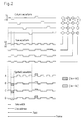
- Figure 2 is a timing chart showing an example of driving waveforms used for driving the ferroelectric liquid crystal device having the ⁇ -V characteristic of Figure 1B .
- Figure 3 is a diagram illustrating a principle of a method for driving using the driving waveforms of Figure 2 .
- Figure 4 is a cross-sectional view of a ferroelectric liquid crystal device of the present invention.
- Figures 5A and 5B are model diagrams showing C1 and C2 orientations in the ferroelectric liquid crystal device of the present invention.
- Figure 6 shows models of four molecular orientations of ferroelectric liquid crystal.
- Figure 7 is a timing chart showing an example of driving waveforms used for driving the ferroelectric liquid crystal device having the ⁇ -V characteristic of Figure 1B .
- Figure 8 is a graph showing a ⁇ -V characteristic of the ferroelectric liquid crystal device of the present invention.
- Figure 9 is a graph showing a ⁇ -V characteristic in the case where a bias is applied to another ferroelectric liquid crystal device of the present invention.
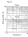
- Figure 10 is a graph showing a ⁇ -V characteristic in the case where a bias is applied to still another ferroelectric liquid crystal device of the present invention.
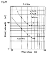
- Figure 11 is a graph showing ⁇ -V characteristics in the case where a bias is applied to the other two ferroelectric liquid crystal devices of the present invention.
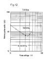
- Figure 12 is a graph showing a ⁇ -V characteristic in the case where a bias is applied to still another ferroelectric liquid crystal device of the present invention.
- Figure 13 is a graph showing a ⁇ -V characteristic in the case where a bias is applied to still another ferroelectric liquid crystal device of the present invention.
- Figure 14 is a graph showing a ⁇ -V characteristic in the case where a bias is applied to still another ferroelectric liquid crystal device of the present invention.
- Figure 15 shows an example of driving waveforms for driving a ferroelectric liquid crystal device using a ⁇ -V min characteristic.
- Figure 16 is a graph showing the relationship between response time and a pulse voltage of a ferroelectric liquid crystal device of a comparative example.
- Figure 17 is a graph showing the relationship between response time and a pulse voltage of a ferroelectric liquid crystal device of another comparative example.
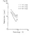
- Figure 18 is a graph showing the relationship between response time and a pulse voltage of a ferroelectric liquid crystal device of still another comparative example.
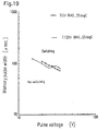
- Figure 19 is a graph showing a ⁇ -V characteristic of a ferroelectric liquid crystal device of a comparative example.
- Figure 20 is a graph showing a ⁇ -V characteristic of a ferroelectric liquid crystal device of another comparative example.
- Optically active substances represented by Formulae IV to VII can be synthesized as follows:
- the above reaction can be carried out by a conventional method.
- R 1 and R 2 are the same or different straight-chain or branched chain alkyl groups having 1 to 15 carbon atoms;
- X 1 is a single bond, -O-, -COO-, or -OCO-;
- X 2 is -O- or -OCO-;
- Y is -COO- or -CH 2 O-;
- a and B are independently a group including a six membered ring which can be substituted by halogen, a cyano group, a lower alkoxy group, or a fluorine-containing alkyl group; and
- Z is a single bond, -COO-, or -OCO-.
- a compound represented by Formula I, where Z is a single bond, -COO-, or -OCO-; Y is -COO-; and X 2 is -O- can be synthesized by the following method, using the optically active substance represented by Formula VII as part of its material.
- R 1 and R 2 are the same or different straight-chain or branched chain alkyl groups having 1 to 15 carbon atoms;
- X 1 is a single bond, -O-, -COO-, or -OCO-;
- a and B are independently a group including a six membered ring which can be substituted by halogen, a cyano group, a lower alkoxy group, or a fluorine-containing alkyl group; and Hal is halogen.
- the reaction in the above method can be carried out in a solvent such as toluene, benzene, and methylene chloride in the presence of an organic base such as pyridine and triethylamine at -20°C to 80°C.
- a solvent such as toluene, benzene, and methylene chloride
- an organic base such as pyridine and triethylamine at -20°C to 80°C.
- a compound represented by Formula I, where Z is a single bond, Y is -COO-, and X 2 is -OCO-, can be synthesized by the following method, using the optically active substance represented by Formula IV as part of its material.
- R 1 and R 2 are the same or different straight-chain or branched chain alkyl groups having 1 to 15 carbon atoms;
- X 1 is a single bond, -O-, -COO-, or -OCO-;
- X 2 is -O- or -OCO-;
- a and B are independently a group including a six membered ring which can be substituted by halogen, a cyano group, a lower alkoxy group, or a fluorine-containing alkyl group; * is asymmetric carbon; and Hal is halogen.
- the esterification (i) in the above method can be effected in a solvent such as toluene, benzene, and methylene chloride in the presence of an organic base such as pyridine and triethylamine in a temperature range of -20°C to 80°C.
- a solvent such as toluene, benzene, and methylene chloride
- an organic base such as pyridine and triethylamine in a temperature range of -20°C to 80°C.
- the desilylation (ii) in the above method can be effected in a solvent of tetrahydrofran in a temperature range of 0°C to 50°C, using tetra-n-butylammonium fluoride as a catalyst.
- the acylation (iii) in the above method can be effected in a solvent such as toluene, benzene, and methylene chloride in the presence of an organic base such as pyridine and triethylamine in a temperature range of -20°C to 80°C.
- a solvent such as toluene, benzene, and methylene chloride
- an organic base such as pyridine and triethylamine in a temperature range of -20°C to 80°C.
- a compound represented by Formula I, where Z is a single bond, Y is -CH 2 O-, and X 2 is -O-, can be synthesized by the following method, using the optically active substance represented by Formula VII as part of its material.
- R 1 and R 2 are the same or different straight-chain or branched chain alkyl groups having 1 to 15 carbon atoms;
- X 1 is a single bond, -O-, -COO-, or -OCO-;
- X 2 is -O- or -OCO-;
- a and B are independently a group including a six membered ring which can be substituted by halogen, a cyano group, a lower alkoxy group, or a fluorine-containing alkyl group; and
- Z' is chlorine, bromine, iodine, or a tosyl group.
- the above-mentioned reaction is carried out by allowing a base such as an alkali metal hydride, sodium hydroxide, and potassium hydroxide to react with the compounds represented by Formula VII and adding the compound represented by Formula VIII to the reaction product.
- a base such as an alkali metal hydride, sodium hydroxide, and potassium hydroxide
- R 1 and R 2 are the same or different straight-chain or branched chain alkyl groups having 1 to 15 carbon atoms;
- X 1 is a single bond, -O-, -COO-, or -OCO-;
- X 2 is -O- or -OCO-;
- Y is -COO- or -CH 2 O-;
- a and B are independently a group including a six membered ring which can be substituted by halogen, a cyano group, a lower alkoxy group, or a fluorine-containing alkyl group; and
- Z is a single bond, -COO-, or -OCO-.
- a compound represented by Formula II, where Z is a single bond and Y is -COO- can be synthesized by the following method, using the optically active substances represented by Formula V or VI as part of its material.
- R 1 and R 2 are the same or different straight-chain or branched chain alkyl groups having 1 to 15 carbon atoms;
- X 1 is a single bond, -O-, -COO-, or -OCO-;
- X 2 is -O- or -OCO-;
- a and B are independently a group including a six membered ring which can be substituted by halogen, a cyano group, a lower alkoxy group, or a fluorine-containing alkyl group; and Hal is halogen.
- the reaction (i) in the above method can be carried out in a solvent such as toluene, benzene, and methylene chloride in the presence of an organic base such as pyridine and triethylamine in a temperature range of -20°C to 80°C.
- a solvent such as toluene, benzene, and methylene chloride
- an organic base such as pyridine and triethylamine in a temperature range of -20°C to 80°C.
- a compound represented by Formula II, where Z is a single bond and Y is -CH 2 O-, can be synthesized by the following method, using the optically active substance represented by Formula V or VI as part of its material.
- R 1 and R 2 are the same or different straight-chain or branched chain alkyl groups having 1 to 15 carbon atoms;
- X 1 is a single bond, -O-, -COO-, or -OCO-;
- X 2 is -O- or -OCO-;
- a and B are independently a group including a six membered ring which can be substituted by halogen, a cyano group, a lower alkoxy group, or a fluorine-containing alkyl group; and
- Z' is chlorine, bromine, iodine, or a tosyl group.
- the reaction (i) in the above method can be carried out by allowing the compound represented by Formula V or VI to react with a base such as alkali metal hydride, sodium hydroxide and potassium hydroxide and then adding the compound represented by Formula VIII to the resulting reaction product.
- a base such as alkali metal hydride, sodium hydroxide and potassium hydroxide
- a compound represented by Formula II, where Z is -COO- and Y is -COO- can be synthesized by the following method, using the optically active substance represented by Formula V or VI as part of its material.
- R 1 and R 2 are the same or different straight-chain or branched chain alkyl groups having 1 to 15 carbon atoms;
- X 1 is a single bond, -O-, -COO-, or -OCO-;
- X 2 is -O- or -OCO-;
- a and B are independently a group including a six membered ring which can be substituted by halogen, a cyano group, a lower alkoxy group, or a fluorine-containing alkyl group; Hal is halogen; and Bz is a benzyl group.
- the reaction (i) in the above method can be carried out in a solvent such as toluene, benzene, and methylene chloride in the presence of an organic base such as pyridine and triethylamine in a temperature range of -20°C to 80°C.
- a solvent such as toluene, benzene, and methylene chloride
- an organic base such as pyridine and triethylamine in a temperature range of -20°C to 80°C.
- the debenzylation (ii) in the above method can be effected by hydrogenolysis at atmospheric pressure, using acetic acid or an alcoholic solvent such as methanol, ethanol, and propanol in the presence of, for example, a palladium carbon (Pd/C) catalyst.
- acetic acid or an alcoholic solvent such as methanol, ethanol, and propanol in the presence of, for example, a palladium carbon (Pd/C) catalyst.
- Pd/C palladium carbon
- reaction (iii) in the above method can be carried out in a solvent of toluene, benzene, and methylene chloride in the presence of an organic base such as pyridine and triethylamine in a temperature range of -20°C to 80°C.
- organic base such as pyridine and triethylamine
- a compound represented by Formula II, where Z is -COO- and Y is -CH 2 O-, can be synthesized by the following method, using the optically reactive substance represented by Formulae V or VI as part of its material.
- R 1 and R 2 are the same or different straight-chain or branched chain alkyl groups having 1 to 15 carbon atoms;
- X 1 is a single bond, -O-, -COO-, or -OCO-;
- X 2 is -O- or -OCO-;
- a and B are independently a group including a six membered ring which can be substituted by halogen, a cyano group, a lower alkoxy group, or a fluorine-containing alkyl group;
- Hal is halogen;
- Z' is chlorine, bromine, iodine, or a tosyl group; and
- Thp is a tetrahydropyranyl group.
- the reaction (i) in the above method can be carried out by allowing the compound represented by Formula V or VI to react with a base such as an alkali metal hydride, sodium hydroxide, and potassium hydroxide and then adding the compound represented by Formula IX to the resulting reaction product.
- a base such as an alkali metal hydride, sodium hydroxide, and potassium hydroxide
- the elimination (ii) of a tetrahydropyranyl group in the above method can be effected, using a solvent such as ether, tetrahydrofuran, and chloroform in the presence of an acid catalyst such as hydrochloric acid, sulfuric acid, and p-toluenesulfonic acid.
- a solvent such as ether, tetrahydrofuran, and chloroform
- an acid catalyst such as hydrochloric acid, sulfuric acid, and p-toluenesulfonic acid.
- the reaction (iii) in the above method can be effected in a solvent such as toluene, benzene, and methylene chloride in the presence of an organic base such as pyridine and triethylamine in a temperature range of -20°C to 80°C.
- a solvent such as toluene, benzene, and methylene chloride
- an organic base such as pyridine and triethylamine in a temperature range of -20°C to 80°C.
- a known compound represented by Formula III can be synthesized by the conventional synthesis method.
- Examples of the conventional synthesis method are described in G. W. Gray, M. Hied and K. J. Toyne, Mol. Cryst. Liq. Cryst., 204, 43 (1991); Japanese Laid-Open Patent Publication Nos. 2-289529, 2-279649, 2-4725, 2-4724; and Japanese National Publication Nos. 2-504520, 2-502914, 2-503568, 2-503443, 2-503441, 2-503436, 2-503431, and 2-503430.
- Ether was removed from the extract under reduced pressure.
- the resulting extract was purified by silica gel column chromatography to obtain 0.25 g (0.5 mM) of intended compound, i.e., (2R, 5R, 6R)-tetrahydro-6-trifluoromethyl-2-hexyloxy-5-(4"-hexyloxybiphenyl-4'-carbonyloxy)pyran.
- Examples of the alkyl group having 1 to 15 carbon atoms represented by R 1 and R 2 in Formulae I and II include methyl, ethyl, n-propyl, n-butyl, isobutyl, n-pentyl, isopentyl, n-hexyl, isohexyl, n-heptyl, isoheptyl, n-octyl, isooctyl, n-nonyl, isononyl, n-decyl, isodecyl, n-undecyl, isoundecyl, n-dodecyl, isododecyl, n-tridecyl, isotridecyl, n-tetradecyl, isotetradecyl, n-pentadecyl, and isopentadecyl.
- Asymmetric carbon can be contained in a carbon chain of these alkyl groups.
- one or more hydrogen in these alkyl groups can be substituted by fluorine, chlorine, bromine, a cyano group, a nitro group, a trifluoromethyl group, a methoxy group, or the like.
- Examples of the group obtained by substituting one or more hydrogen in these alkyl groups include 1-trifluoromethylheptyl, 1-fluorooctyl, and 1-chloro-2-methyl-butyl.
- Examples of the group including a six membered ring represented by A and B include heterocyclic groups including a six membered ring having one or two nitrogen atoms (e.g., pyridine-2,5-diyl, pyrimidine-2,5-diyl, pyridazine-3,6-diyl); aromatic hydrocarbon groups (e.g., phenylene, nephthalene-2,6-diyl); and saturated hydrocarbon group including a six membered ring which can have one or two oxygen atoms (e.g., cyclohexadinyl, tetrahydropyran-2,5-diyl, dioxane-2,5-diyl).
- heterocyclic groups including a six membered ring having one or two nitrogen atoms e.g., pyridine-2,5-diyl, pyrimidine-2,5-diyl, pyridazine-3,6-d
- These groups including a six membered ring can be substituted by one or two groups selected from a halogen group (e.g., chloro, fluoro) , a cyano group, a lower alkoxy group (e.g., methoxy, ethoxy), and a fluorine-containing alkyl group (e.g., monofluoromethyl, difluoromethyl, trifluoromethyl, monofluoroethyl).
- a halogen group e.g., chloro, fluoro
- a cyano group e.g., cyano group
- a lower alkoxy group e.g., methoxy, ethoxy
- a fluorine-containing alkyl group e.g., monofluoromethyl, difluoromethyl, trifluoromethyl, monofluoroethyl.
- Examples of the chiral compound represented by Formula I include the following compounds and enantiomers thereof.
- Examples of the chiral compound represented by Formula II include the following compounds and enantiomers thereof.
- the ferroelectric liquid crystal mixture of the present invention can be prepared by adding the chiral compound represented by Formula I or II to a liquid crystal mixture having negative dielectric anisotropy and exhibiting a smectic C phase.
- the chiral compound represented by Formula I or II can be used alone or in combination of two or more kinds thereof.
- the chiral compound represented by Formula I or II can be used together with other known chiral compounds.
- the ferroelectric liquid crystal mixture of the present invention can also be prepared by adding the achiral compound (racemic body) represented by Formula I or II to a ferroelectric liquid crystal mixture having negative dielectric anisotropy and exhibiting a chiral smectic C phase.
- the chiral compound to be added to the liquid crystal mixture can be the chiral compound represented by Formula I or II, other known chiral compounds, or mixtures of these compounds.
- the chiral compound represented by Formula I or II to be added to the liquid crystal mixture regulates the helical pitch of a liquid crystal phase, thereby improving orientation of liquid crystal molecules.
- the chiral compound is added to the liquid crystal mixture preferably in an amount of 0.01 to 5 wt%, more preferably 0.01 to 3 wt%.
- the added amount of the compound is less than 0.01 wt%, the compound does not sufficiently work as a chiral agent.
- the added amount of the compound is more than 5 wt%, the spontaneous polarization of the mixture becomes too large, so that V min becomes too high to drive.
- the achiral compound is added to the ferroelectric liquid crystal mixture preferably in an amount of 5 to 20 wt%.
- liquid crystalline compound used for the ferroelectric liquid crystal mixture of the present invention examples include liquid crystalline compounds of an ester type, biphenyl type, terphenyl type, pyrimidine type, pyridine type, or the like; and liquid crystalline compounds obtained by substituting a hydrogen atom in a lateral direction of these liquid crystalline compounds by a halogen atom, a CN group, or the like. These liquid crystalline compounds are represented by Formula III.
- liquid crystalline compounds can be appropriately mixed.
- liquid crystal mixtures having negative dielectric anisotropy and exhibiting a smectic C phase liquid crystal mixtures exhibiting a phase sequence of Isotropic-Smectic A-Smectic C (IAC) or Isotropic-Nematic-Smectic A-Smectic C (INAC) are particularly preferred because of their satisfactory orientation property and bistability.
- IAC Isotropic-Smectic A-Smectic C
- INAC Isotropic-Nematic-Smectic A-Smectic C
- Ferroelectric liquid crystal mixtures FLC1 to FLC5 of the present invention were prepared.
- a ferroelectric liquid crystal mixture was prepared by adding the chiral compound represented by Formula I or II to a liquid crystal mixture made of the liquid crystalline compound represented by Formula III.
- chiral compounds represented by Formula I or II shown in Table 1 were obtained in accordance with Synthesis Examples. Then, each of the chiral compounds thus obtained was added in an amount of 2 wt% to an achiral liquid crystal mixture shown in Table 2 to obtain ferroelectric liquid crystal mixtures.
- the transition temperature, response time, spontaneous polarization, helical pitch in a chiral nematic phase, and tilt angle are also shown in Table 1.
- liquid crystal mixtures LC1 to LC5 shown in Table 4 were prepared using liquid crystalline compounds represented by Formula III shown in Table 3.
- the transition temperature of the liquid crystal mixtures LC1 to LC5 are shown in Table 5.
- Table 4 LC1 LC2 LC3 LC4 LC5 FA-050 5.6% FA-067 16.1% 10.0% FA-068 16.5% 10.0% FA-069 5.3% FA-075 12.3% 12.5% 10.0% 15.0% 10.0% FA-076 16.5% FA-077 5.0% FA-078 10.0% FA-081 12.5% 10.0% 15.0% 10.0% FA-083 12.5% 10.0% 15.0% 10.0% FA-087 12.5% 10.0% 15.0% 10.0% FA-090 10.0% FB-021 12.5% 10.0% 10.0% 10.0% FB-022 11.3% 12.5% 10.0% 10.0% 10.0% FB-029 11.4% 12.5% 10.0% 10.0% 10.0% 10.0% FB-038 12.5% 10.0% 10.0% 10.0% 10.0% Table 5 K S C S A N I LC1 ⁇ RT ⁇ 77 ⁇ 84 ⁇
- the ferroelectric liquid crystal mixtures FLC1 to FLC5 shown in Table 6 were prepared using the liquid crystal mixtures LC1 to LC 5 and the chiral compounds shown in Table 1.
- the transition temperature of the ferroelectric liquid crystal mixtures FLC1 to FLC5 are shown in Table 7.
- Ferroelectric liquid crystal mixtures FLC6 to FLC8 were prepared.
- a ferroelectric liquid crystal mixture was prepared by adding the achiral compound represented by Formula I or II to a known ferroelectric liquid crystal mixture.
- ferroelectric liquid crystal mixture SCE8 manufactured by Merck & Co., Inc. was used.
- the achiral compounds (racemic bodies) represented by Formulae I and II shown in Table 8 were obtained in accordance with Synthesis Examples.
- the racemic bodies shown in Table 8 were respectively added to SCE8 to prepare the ferroelectric liquid crystal mixtures FLC6 to FLC8 shown in Table 9.
- the transition temperature of the ferroelectric liquid crystal mixtures FLC6 to FLC8 are shown in Table 10.
- a liquid crystal device of the present invention will be described.
- FIG 4 is a cross-sectional view of a transmission type liquid crystal device using the ferroelectric liquid crystal mixture of the present invention.
- the liquid crystal device shown in Figure 4 includes insulating substrates 1a , 1b , transparent electrodes 2a , 2b , insulating films 3a , 3b , alignment films 4a , 4b , a sealant 6 , ferroelectric liquid crystal 7 , and polarizing plates 12a , 12b .
- the insulating substrates 1a , 1b transparent substrates such as glass substrates are generally used.
- the transparent electrodes 2a , 2b having a predetermined pattern, made of a conductive thin film such as InO 3 , SnO 2 , and Indium-Tin Oxide (ITO) are respectively formed on the insulating substrates 1a , 1b .
- the insulating films 3a , 3b are generally formed. It is not necessary that the insulating films 3a , 3b are formed thereon.
- an inorganic thin film such as SiO 2 , SiNx, and Al 2 O 3
- an organic thin film such as polyimide, photoresist resin, and polymer liquid cryscan be used.
- the inorganic thin film can be formed by vacuum evaporation, sputtering, chemical vapor deposition (CVD), or solution coating.
- the organic thin film can be formed by coating a solution of an organic substance by spinner coating, dip coating, screen printing, roller coating, or the like and curing the solution if required.
- the organic thin film can also be formed by vacuum evaporation, sputtering, CVD, Langumuir-Blodgett (LB) or the like.
- the alignment films 4a , 4b are formed on the insulating films 3a , 3b . In the case where the insulating films 3a , 3b are not formed, the alignment films 4a , 4b are directly formed on the transparent electrodes 2a , 2b .
- an inorganic film or an organic film can be used as the alignment films 4a , 4b .
- a silicon oxide film which is oblique-deposited by evaporation is often used as the alignment film of an inorganic type.
- a silicon oxide film which is rotation-deposited by evaporation can also be used.
- a thin film of SiO 2 , SiNx or the like is formed by vacuum evaporation, sputtering, CVD, or the like, and the surface of the resulting film is rubbed to form an alignment film.
- Nylon, polyvinyl alcohol, polyimide, and the like can be used as the organic alignment film.
- the surface of such an organic film is rubbed to form an alignment film.
- a polymer liquid crystal film and an LB film can be used as the alignment film.
- liquid crystal can be oriented using a magnetic field or by a spacer edge method. Two insulating substrates on which the alignment films are formed are attached to each other, and then ferroelectric liquid crystal is injected therebetween to obtain the ferroelectric liquid crystal device of the present invention.
- rubbing method As described above, various methods can be used for the alignment of liquid crystal in the ferroelectric liquid crystal device. Among them, the method which is most excellent in mass-production is a rubbing method. There are mainly three kinds of rubbing methods: parallel rubbing, antiparallel rubbing, and rubbing of only one substrate. According to parallel rubbing, upper and lower substrates are rubbed and the respective rubbing directions are parallel. According to antiparallel rubbing, upper and lower substrates are rubbed, and the respective rubbing directions are antiparallel with each other. According to the rubbing of only one substrate, only one of upper and lower substrates is rubbed.
- a ferroelectric liquid crystal material is optically active liquid crystal.
- the ferroelectric liquid crystal material exhibits a nematic phase on a higher temperature side, the nematic phase has a helical structure, leading to the difficulty of obtaining uniform orientation. If the ferroelectric liquid crystal material does not exhibit a nematic phase on a higher temperature side, such a problem is not caused. However, in this case, an isotropic liquid state is directly changed to a smectic phase. Thus, it is also difficult to obtain satisfactorily uniform orientation.
- the most effective method for obtaining uniform orientation is that a ferroelectric liquid crystal material having an INAC phase sequence is used in a parallel rubbing cell.
- a ferroelectric liquid crystal material having an INAC phase sequence is used in a parallel rubbing cell.
- the orientation of molecules are regulated by both sides of the upper and lower substrates.
- the orientation in the chiral smectic C phase is not limited to one.
- the reasons why uniform orientation cannot be obtained over the entire surface of the substrates are two reasons why uniform orientation cannot be obtained over the entire surface of the substrates.
- One of the reasons is concerned with the bend of a smectic layer.
- the ferroelectric liquid crystal has a bent layer structure (i.e., chevron structure).
- chevron structure As shown in Figure 5 , in the chevron structure, there are two regions. Kanbe et al. call these regions C1 and C2, considering the relationship with a pretilt angle.
- the other reason is concerned with uniformity (U) and twist (T). Uniformity refers to orientation showing an extinction direction and twist refers to orientation showing no extinction direction.
- C1U In C1T and C2T, the extinction direction is not present and a black state is not sufficiently black, so that a satisfactory contrast cannot be obtained.
- C1U is difficult to be switched, and even though it is switched, C1U is changed to any orientation in which C2 is mixed during driving.
- the inventors of the present invention has found that C2U provides a satisfactory contrast.
- the occurrence of C1 and C2 is related to a pretilt angle.
- C2 When the pretilt angle is in the range of 0° to 15°, C2 will occur.
- C2U the pretilt angle
- the pretilt angle is preferably in the range of 5° to 10° so as to obtain C2U.
- the method for driving shown in Figure 2 can be used; A more preferred method for driving is shown in Figure 7 .
- the method shown in Figure 7 is capable of partially rewriting.
- This driving method is preferred for realizing a display of large capacity such as 2000 x 2000 lines, using the ferroelectric liquid crystal device.
- a driving voltage having a waveform (1) is applied to scanning electrodes connected to pixels to be rewritten, and a driving voltage having a waveform (2) is applied to the other scanning electrodes.
- a driving voltage having a waveform (4) is applied to signal electrodes connected to pixels which are not to be rewritten.
- the same waveform is repeated (n-1)/2 times; however, the repetition time can be appropriately set at one or more.
- driving voltages having waveforms (5) to (8) are set so that the intensity of transmitted light obtained when these driving voltages are applied to pixels are almost equal. Thus, a satisfactory display without flickering can be realized.
- Each ferroelectric liquid crystal device was placed between two polarizers orthogonal to each other. Each device was evaluated for the relation ( ⁇ - V min characteristic) between a pulse width (memory pulse width) required for memory and a voltage.
- the results obtained with respect to FLC1 to FLC3 are shown in Figures 8 to 10 ; those obtained with respect to FLC4 and FLC5 are shown in Figure 11 ; and those obtained with respect to FLC6 to FLC8 are shown in Figures 12 to 14 .
- V min can be recognized.
- a driving test was conducted in the ferroelectric liquid crystal devices fabricated in Example 9, using driving waveforms shown in Figure 7 .
- Driving conditions and results of the driving test are shown in Table 11.
- the devices can be switched by a driving voltage of 40 V or less and a contrast ratio of 20 : 1 or more can be obtained.
- the angle between two memory states during driving was 47°; thus, a bright display was obtained.
- a driving test was conducted in the ferroelectric liquid crystal devices fabricated in Example 9, using driving waveforms shown in Figure 2 .
- Driving conditions and results of the driving test are shown in Table 12.
- the devices can be switched by a driving voltage of 40 V or less and a contrast ratio of 20 : 1 or more can be obtained.
- a driving test was conducted in the ferroelectric liquid crystal devices fabricated in Example 9, using driving waveforms shown in Figure 15 .
- Driving conditions and results of the driving test are shown in Table 13.
- the devices can be switched by a driving voltage of 40 V or less and a contrast ratio of 20 : 1 or more can be obtained.
- the ferroelectric liquid crystal device has ferroelectric liquid crystal sandwiched between a pair of insulating substrates, each having at least an electrode film and an alignment film.
- the device includes a driving unit for switching an optical axis of liquid crystal by selectively applying a voltage to the electrode and a unit for optically identifying the optical axis.
- the ferroelectric liquid crystal is the above-mentioned liquid crystal mixture.
- the electrodes of the liquid crystal device are arranged so as to cross each other, whereby a plurality of scanning electrodes and a plurality of signal electrodes are formed. Each crossed region of the scanning electrodes and the signal electrodes forms a pixel. It is preferred that a positive voltage pulse or a negative voltage pulse lower than a local minimum value V min is applied to a pixel composed of a scanning electrode to which a non-selection voltage is applied and a signal electrode to which a rewrite voltage is applied; A positive voltage pulse or a negative voltage pulse higher than the local minimum value V min and a negative voltage or a positive voltage lower than the local minimum value V min are applied to a pixel composed of a scanning electrode to which a selection voltage is applied and a signal electrode to which a holding voltage is applied; and a positive voltage pulse (or a negative voltage pulse) suitable for switching (i.e., a voltage pulse in the vicinity of the local minimum value V min in the voltage-pulse width characteristic) is applied to a pixel composed of a
- the prepared ferroelectric liquid crystal mixture has a low local minimum value V min , spontaneous polarization should be decreased to some extent. Considering this, the spontaneous polarization is preferably 10 nC/cm 2 or less. Considering the orientation property, the prepared ferroelectric liquid crystal mixture preferably exhibits a chiral nematic phase, a smectic A phase, and a chiral smectic C phase.
- Ferroelectric liquid crystal mixtures CFLC1 to CFLC4 each having a composition shown in Table 15 were prepared, using the liquid crystal mixture CLC1 having a composition shown in Table 14 and the compound shown in Table 1.
- the transition temperature of the ferroelectric liquid crystal mixtures CFLC1 to CFLC4 is shown in Table 16.
- the dielectric anisotropy of the ferroelectric liquid crystal mixtures CFLC1 to CFLC4 is in the vicinity of 0.
- Each of the ferroelectric liquid crystal devices thus obtained was placed between two polarizers orthogonal to each other. Each device was evaluated for the relation between the response time and an applied voltage. Under the condition that the temperature of the device was set at 25°C, various voltages with a rectangular waveform were applied to the cell. Time required for the relative transmittance to change from 0% to 50%, 0% to 90%, and 10% to 90% was measured.
- the ferroelectric liquid crystal mixture of the present invention has spontaneous polarization of 10 to 0.5 nC/cm 2 .
- the ferroelectric liquid crystal device using the ferroelectric liquid crystal mixture of the present invention has a satisfactory orientation property, a high contrast, and a large capacity at a low driving voltage.
Description
- The present invention relates to a ferroelectric liquid crystal mixture and a liquid crystal device using the same.
- Liquid crystal display devices which have been most widely used in recent years employ a nematic phase of liquid crystal. In twisted nematic (TN) liquid crystal display devices, it is difficult to realize a display with a large capacity, e.g., 2000 x 2000 lines, since contrast decreases with the increase in the number of lines. In order to improve the TN liquid crystal display devices, supertwisted nematic (STN) liquid crystal display devices and double layer supertwisted nematic (DSTN) liquid crystal display devices have been developed. However, in these devices, contrast decreases and response time becomes longer with the increase in the number of lines; therefore, display capacity is now limited to about 800 x 1024 lines.
- Active matrix type liquid crystal display devices have been developed to realize a display with a large capacity, e.g., 1000 x 1000 lines. These devices also have disadvantages such as many steps for prolonged production, a decrease in yield, and high production cost.
- In recent years, in addition to liquid crystal display devices employing a nematic phase, those employing a smectic phase have been extensively studied. In particular, a ferroelectric liquid crystal display device has been considered to be promising (N. A. Clark et al., Appl. Phys. Lett., 36, 899 (1980)). The ferroelectric liquid crystal display device employs a memory property of a chiral smectic C phase, a chiral smectic I phase, and the like. Because of this, the ferroelectric liquid crystal display device enables a display with a large capacity accompanied by the decrease in response time. In addition, since the ferroelectric liquid crystal display device does not require an active element such as a thin film transistor, production cost is not likely to increase. Furthermore, the ferroelectric liquid crystal display device has an advantage of a large viewing angle, so that it has been promising as a display device with a large capacity, e.g., 2000 x 2000 lines.
- There are various problems to be solved for putting the ferroelectric liquid crystal display device into practical use. Among them, it is most important to find a means for realizing high contrast in a simple matrix drive. Regarding this problem, the following methods have been proposed.
- (1) A method for using oblique vacuum evaporation
- (2) A method for using a high pretilt alignment film
- (3) A method for processing using an AC electric field
- (4) A method for using a naphthalene compound
- (5) A method for using C1-uniform orientation
- (6) A method for using a liquid crystal material having negative dielectric anisotropy
- A method (1) is proposed in T. Uemura et al., Proc. SID, 175 (1987) . This method requires oblique vacuum evaporation, making it difficult to mass-produce a device and to obtain a device with a large area. Another method (2) is proposed in N. Yamamoto et al., Jpn. J. Appl. Phys., 28, 524 (1989). According to the experiences of the inventors, it is not so easy to obtain uniform orientation in a large area using a high pretilt alignment film. Another method (3) is proposed in Y. Sato et al., Jpn. J. Appl. Phys., 28, L483 (1989) and in H. Rieger et al., Proc. SID, 396 (1991) . According to this method, an AC electric field with a low frequency and a high voltage is applied to a conventional ferroelectric liquid crystal cell, whereby a chevron structure in a cell is forced to be changed to a quasi-Bookshelf geometry which is nearly ideal. The method (3) has advantages such as a high contrast, a large memory angle and a bright display; however, there are still problems preventing its practical use, such as increased response time and a change in characteristics with time during driving. Another method (4) is proposed in A. Mochizuki et al., Ferroelectrics., 122, 37 (1991). According to this method, a quasi-Bookshelf geometry which is nearly ideal is obtained using a specific naphthalene compound to realize high contrast. However, naphthalene compounds to be used are limited, so that a great amount of difficulty is assumed for realizing a practical ferroelectric liquid crystal display device with a large screen and a large display capacity, using this method. Another method (5) is proposed in Koden et al., "Future Liquid Crystal Display and its Materials Ferroelectric liquid crystal and antiferroelectric liquid crystal", p. 114 (1992) (under the supervision of A. Fukuda). According to this method, high contrast is obtained employing specific orientation such as Cl-uniform obtained in a parallel rubbing liquid crystal cell using an alignment film with a high pretilt angle. Here, "a parallel rubbing cell" refers to a liquid crystal cell fabricated so that rubbing directions of the upper and lower alignment films are identical. In this method, it is difficult to selectively obtain Cl-uniform orientation in a large area.
- Another method (6) is proposed in P.W.H. Surguy et al., Ferroelectrics, 122, 63 (1991). This method is a promising method for realizing high contrast. A sample of a ferroelectric liquid crystal display device has already been fabricated using this method (P.W. Ross, Proc. SID, 217 (1992)).
- Hereinafter, the method (6) will be described in detail.
- A conventional ferroelectric liquid crystal material whose dielectric anisotropy is not negative exhibits a τ-V characteristic shown in Figure 1A. More specifically, τ (a memory pulse width, or a pulse width required for memory) monotonously decreases with the increase in voltage. In contrast, a ferroelectric liquid crystal material having negative dielectric anisotropy exhibits a τ-V (τ-Vmin) characteristic having a local minimum value Vmin shown in Figure 1B. Surguy et al. have reported a driving method shown in Figure 2 as a driving method using this characteristic (P.W.H. Surguy et al., Ferroelectrics, 122, 63 (1991)). The principle of this driving method is briefly shown in Figure 3. According to the principle, when a voltage of |Vs-Vd| is applied, memory states are switched in the ferroelectric liquid crystal display device, and when a voltage of |Vs+Vd| which is higher than |Vs-Vd| and a voltage of |Vd| which is lower than |Vs-Vd| is applied, the memory states are not switched.
- A problem of the method (6) lies in the high driving voltage. According to the report of Ross et al. (P.W. Ross, Proc. SID, 217 (1992)), the driving voltage of a sample of a ferroelectric liquid crystal display device is 55 V. The price of an IC driver for driving the ferroelectric liquid crystal display device goes up with the increase in voltage, so that a high driving voltage necessitates the increase in production cost. In order to fabricate a ferroelectric liquid crystal display device at reasonable price, it is required to drive the display with an inexpensive general-purpose IC driver. That is, it is required that a driving voltage is no more than 40 V. A high driving voltage is due to a high local minimum value Vmin in the τ-Vmin characteristic. Thus, in order to drive a display with a driving voltage of 40 V or less, a ferroelectric liquid crystal display material exhibiting a local minimum value of about 30 V needs to be developed.
- According to Surguy et al. (P.W.H. Surguy et al., Ferroelectrics, 122, 63 (1991)), a local minimum value Vmin is given by the following equation:

- In general, the ferroelectric liquid crystal mixture is prepared by adding a chiral compound to an achiral liquid crystal mixture exhibiting a smectic C phase. Therefore, it is required that a chiral compound which can cause high response in a small amount is added to an achiral liquid crystal mixture having low viscosity. A chiral compound generally has high viscosity, so that its added amount is preferably small.
- In order to obtain a satisfactory ferroelectric liquid crystal device, the following conventional conditions should also be satisfied.
- (1) The ferroelectric liquid crystal material exhibits a chiral smectic C phase in a wide range of temperature around room temperature.
- (2) The ferroelectric liquid crystal material exhibits a phase sequence of IAC (Isotropic-Smectic A-Smectic C) or INAC (Isotropic-Nematic-Smectic A-Smectic C) so as to obtain satisfactory orientation properties and bistability.
- (3) The helical pitch of the chiral nematic phase and the chiral smectic C phase is sufficiently longer than the cell thickness.
- (4) The ferroelectric liquid crystal material has satisfactory chemical stability and optical stability.
- If required, the tilt angle, refractive index, specific resistance, and the like can be optimized.
- The ferroelectric liquid crystal mixture of this invention, including at least one chiral compound, having negative dielectric anisotropy and exhibiting a chiral smectic C phase, contains at least one compound selected from the group consisting of a compound represented by the following general Formula I:


- In one embodiment of the present invention, the compound represented by Formula I and the compound represented by Formula II are chiral compounds.
- In another embodiment of the present invention, the above-mentioned ferroelectric liquid crystal mixture contains the chiral compound represented by Formula I and the chiral compound represented by Formula II.
- In another embodiment of the present invention, the above-mentioned ferroelectric liquid crystal mixture exhibits a chiral smectic C phase, a smectic A phase, and a chiral nematic phase.
- In another embodiment of the present invention, the above-mentioned ferroelectric liquid crystal mixture contains a compound represented by the following general Formula III:

- In another embodiment of the present invention, R1 and R2 are independently a straight chain or branched chain alkyl group having 5 to 8 carbon atoms, A and B are independently a phenylene group which can be substituted by halogen, a cyano group, a lower alkoxy group, or a fluorine-containing alkyl group, and Z is a single bond in Formula I or II.
- In another embodiment of the present invention, the chiral compound is selected from the group consisting of a compound represented by the following Formulae and enantiomers thereof.


- In another embodiment of the present invention, the chiral compound is selected from the group consisting of a compound represented by the following Formulae and enantiomers.


- In another embodiment of the present invention, the above-mentioned ferroelectric liquid crystal mixture contains the compound represented by Formula I in an amount of 0.01 to 5 wt% based on the total amount of the ferroelectric liquid crystal mixture.
- In another embodiment of the present invention, the above-mentioned ferroelectric liquid crystal mixture contains the compound represented by Formula II in an amount of 0.01 to 5 wt% based on the total amount of the ferroelectric liquid crystal mixture.
- In another embodiment of the present invention, the compound represented by Formula I and the compound represented by Formula II are achiral compounds, and the achiral compounds are contained in the above-mentioned ferroelectric liquid crystal mixture in an amount of 5 to 20 wt% based on the total amount of the ferroelectric liquid crystal mixture.
- According to another aspect of the present invention, a liquid crystal device comprises a pair of facing substrates, liquid crystal sandwiched between the pair of substrates, means for aligning the liquid crystal, and means for applying a voltage to the liquid crystal, wherein the liquid crystal is made of a ferroelectric liquid crystal mixture having negative dielectric anisotropy and exhibiting a chiral smectic C phase containing a compound selected from the group consisting of the compound represented by Formula I and the compound represented by Formula II.
- In one embodiment of the present invention, the compound represented by Formula I and the compound represented by Formula II are chiral compounds.
- Thus, the invention described herein makes possible the advantage of providing a ferroelectric liquid crystal mixture having a low local minimum value Vmin and a liquid crystal device using the same.
- This and other advantages of the present invention will become apparent to those skilled in the art upon reading and understanding the following detailed description with reference to the accompanying figures.
- Figures 1A and 1B are graphs showing τ-V characteristics of ferroelectric liquid crystal devices.
- Figure 2 is a timing chart showing an example of driving waveforms used for driving the ferroelectric liquid crystal device having the τ-V characteristic of Figure 1B.
- Figure 3 is a diagram illustrating a principle of a method for driving using the driving waveforms of Figure 2.
- Figure 4 is a cross-sectional view of a ferroelectric liquid crystal device of the present invention.
- Figures 5A and 5B are model diagrams showing C1 and C2 orientations in the ferroelectric liquid crystal device of the present invention.
- Figure 6 shows models of four molecular orientations of ferroelectric liquid crystal.
- Figure 7 is a timing chart showing an example of driving waveforms used for driving the ferroelectric liquid crystal device having the τ-V characteristic of Figure 1B.
- Figure 8 is a graph showing a τ-V characteristic of the ferroelectric liquid crystal device of the present invention.
- Figure 9 is a graph showing a τ-V characteristic in the case where a bias is applied to another ferroelectric liquid crystal device of the present invention.
- Figure 10 is a graph showing a τ-V characteristic in the case where a bias is applied to still another ferroelectric liquid crystal device of the present invention.
- Figure 11 is a graph showing τ-V characteristics in the case where a bias is applied to the other two ferroelectric liquid crystal devices of the present invention.
- Figure 12 is a graph showing a τ-V characteristic in the case where a bias is applied to still another ferroelectric liquid crystal device of the present invention.
- Figure 13 is a graph showing a τ-V characteristic in the case where a bias is applied to still another ferroelectric liquid crystal device of the present invention.
- Figure 14 is a graph showing a τ-V characteristic in the case where a bias is applied to still another ferroelectric liquid crystal device of the present invention.
- Figure 15 shows an example of driving waveforms for driving a ferroelectric liquid crystal device using a τ-Vmin characteristic.
- Figure 16 is a graph showing the relationship between response time and a pulse voltage of a ferroelectric liquid crystal device of a comparative example.
- Figure 17 is a graph showing the relationship between response time and a pulse voltage of a ferroelectric liquid crystal device of another comparative example.
- Figure 18 is a graph showing the relationship between response time and a pulse voltage of a ferroelectric liquid crystal device of still another comparative example.
- Figure 19 is a graph showing a τ-V characteristic of a ferroelectric liquid crystal device of a comparative example.
- Figure 20 is a graph showing a τ-V characteristic of a ferroelectric liquid crystal device of another comparative example.
- A method for synthesizing a compound contained in a ferroelectric liquid crystal mixture of the present invention will be described in the following order:
- 1. A method for synthesizing optically active substances (chiral compounds) represented by the following general Formulae IV to VII which are materials for compounds represented by Formulae I and II.
- 2. A method for synthesizing a compound represented by Formula I.
- 3. A method for synthesizing a compound represented by Formula II.
In particular, a method for synthesizing chiral compounds represented by Formulae I and II will be described. The chiral compounds represented by Formulae I and II are synthesized using, as materials, optically active substances (chiral compounds) represented by Formulae IV to VII. In the case where achiral compounds (racemic bodies) represented by Formulae I and II are synthesized, achiral compounds represented by Formulae IV to VII can be used as materials. - 4. A method for synthesizing a known compound represented by Formula III.
- 1. Synthesis of optically active substances represented by Formulae IV to VII:


- Optically active substances represented by Formulae IV to VII can be synthesized as follows:

- The above reaction can be carried out by a conventional method.
- 2. Synthesis of a chiral compound (compound with a CF3 group facing outward) represented by Formula I:

- (1) A compound represented by Formula I, where Z is a single bond, -COO-, or -OCO-; Y is -COO-; and X2 is -O- can be synthesized by the following method, using the optically active substance represented by Formula VII as part of its material.

- The reaction in the above method can be carried out in a solvent such as toluene, benzene, and methylene chloride in the presence of an organic base such as pyridine and triethylamine at -20°C to 80°C.
- (2) A compound represented by Formula I, where Z is a single bond, Y is -COO-, and X2 is -OCO-, can be synthesized by the following method, using the optically active substance represented by Formula IV as part of its material.


- The esterification (i) in the above method can be effected in a solvent such as toluene, benzene, and methylene chloride in the presence of an organic base such as pyridine and triethylamine in a temperature range of -20°C to 80°C.
- The desilylation (ii) in the above method can be effected in a solvent of tetrahydrofran in a temperature range of 0°C to 50°C, using tetra-n-butylammonium fluoride as a catalyst.
- The acylation (iii) in the above method can be effected in a solvent such as toluene, benzene, and methylene chloride in the presence of an organic base such as pyridine and triethylamine in a temperature range of -20°C to 80°C.
- (3) A compound represented by Formula I, where Z is a single bond, Y is -CH2O-, and X2 is -O-, can be synthesized by the following method, using the optically active substance represented by Formula VII as part of its material.

- The above-mentioned reaction is carried out by allowing a base such as an alkali metal hydride, sodium hydroxide, and potassium hydroxide to react with the compounds represented by Formula VII and adding the compound represented by Formula VIII to the reaction product.
- 3. Synthesis of a chiral compound (compound with a CF3 group facing inward) represented by Formula II:

- (1) A compound represented by Formula II, where Z is a single bond and Y is -COO-, can be synthesized by the following method, using the optically active substances represented by Formula V or VI as part of its material.

- The reaction (i) in the above method can be carried out in a solvent such as toluene, benzene, and methylene chloride in the presence of an organic base such as pyridine and triethylamine in a temperature range of -20°C to 80°C.
- (2) A compound represented by Formula II, where Z is a single bond and Y is -CH2O-, can be synthesized by the following method, using the optically active substance represented by Formula V or VI as part of its material.

- The reaction (i) in the above method can be carried out by allowing the compound represented by Formula V or VI to react with a base such as alkali metal hydride, sodium hydroxide and potassium hydroxide and then adding the compound represented by Formula VIII to the resulting reaction product.
- (3) A compound represented by Formula II, where Z is -COO- and Y is -COO- can be synthesized by the following method, using the optically active substance represented by Formula V or VI as part of its material.

- The reaction (i) in the above method can be carried out in a solvent such as toluene, benzene, and methylene chloride in the presence of an organic base such as pyridine and triethylamine in a temperature range of -20°C to 80°C.
- The debenzylation (ii) in the above method can be effected by hydrogenolysis at atmospheric pressure, using acetic acid or an alcoholic solvent such as methanol, ethanol, and propanol in the presence of, for example, a palladium carbon (Pd/C) catalyst.
- The reaction (iii) in the above method can be carried out in a solvent of toluene, benzene, and methylene chloride in the presence of an organic base such as pyridine and triethylamine in a temperature range of -20°C to 80°C.
- (4) A compound represented by Formula II, where Z is -COO- and Y is -CH2O-, can be synthesized by the following method, using the optically reactive substance represented by Formulae V or VI as part of its material.

- The reaction (i) in the above method can be carried out by allowing the compound represented by Formula V or VI to react with a base such as an alkali metal hydride, sodium hydroxide, and potassium hydroxide and then adding the compound represented by Formula IX to the resulting reaction product.
- The elimination (ii) of a tetrahydropyranyl group in the above method can be effected, using a solvent such as ether, tetrahydrofuran, and chloroform in the presence of an acid catalyst such as hydrochloric acid, sulfuric acid, and p-toluenesulfonic acid.
- The reaction (iii) in the above method can be effected in a solvent such as toluene, benzene, and methylene chloride in the presence of an organic base such as pyridine and triethylamine in a temperature range of -20°C to 80°C.
- 4. A known compound represented by Formula III can be synthesized by the conventional synthesis method. Examples of the conventional synthesis method are described in G. W. Gray, M. Hied and K. J. Toyne, Mol. Cryst. Liq. Cryst., 204, 43 (1991); Japanese Laid-Open Patent Publication Nos. 2-289529, 2-279649, 2-4725, 2-4724; and Japanese National Publication Nos. 2-504520, 2-502914, 2-503568, 2-503443, 2-503441, 2-503436, 2-503431, and 2-503430.
- Hereinafter, the synthesis method will be described by way of illustrative synthesis examples.
- As examples of compounds represented by Formulae IV to VII, (2R, 5S, 6S)-tetrahydro-6-trifluoromethyl-2-hexyloxy-5-hydroxypyrane and (2S, 5S, 6S)-tetrahydro-6-trifluoromethyl-2-hexyloxy-5-hydroxypyran were synthesized as follows:

- (a) First, 13.6 g (200 mM) of furan was added to 150 ml of tetrahydrofuran in an atmosphere of nitrogen. Then, 133 ml (200 mM) of hexane solution containing 1.5 mol/l of n-butyllithium was dropped into the mixture at -20°C and allowed to react for one hour. To the reaction mixture, 21.7 g (200 mM) of trimethylsilyl chloride was dropped and stirred at -20°C for one hour. To the resulting reaction mixture, 133 ml (200 mM) of hexane solution containing 1.5 mol/l of n-butyllithium was added and allowed to react at -20°C for one hour. Then, 28.4 g (200 mM) of trifluoroethyl acetate was dropped into the reaction mixture thus obtained and allowed to react at -78°C for one hour and at room temperature for another one hour. To the reaction solution, 3 N hydrochloric acid was added to stop the reaction, and the reaction solution was extracted with ethyl acetate. Then, the extract was washed successively with a saturated sodium hydrogen carbonate and brine and dried with magnesium sulfate anhydride. Ethyl acetate was removed from the extract under reduced pressure to obtain a crude product of a furan derivative.
- (b) First, 2.3 g (60 mM) of sodium borohydride was added to 100 ml of dry ethanol. The crude product of the furan derivative obtained in the above reaction was dropped into the mixture at 0°C over 30 minutes. The resulting mixture was allowed to react at room temperature for 2 hours, and ethanol was distilled under reduced pressure. To the reaction solution, 3 N hydrochloric acid was added to stop the reaction and extracted with ethyl acetate. Then, the extract was washed successively with a saturated sodium hydrogen carbonate and brine and dried with magnesium sulfate anhydride. Ethyl acetate was removed from the extract under reduced pressure, and then the extract was distilled under reduced pressure to obtain 40.5 g (170 mM) of alcohol compound.
- (c) First, 23.8 g (100 mM) of alcohol compound obtained in the above reaction (b) and 8.9 ml (110 mM) of pyridine were added to 200 ml of methylene chloride. Then, 8.6 g (110 mM) of acetyl chloride was dropped into the mixture at 0°C and allowed to react at room temperature for 12 hours. To the reaction solution, 3 N hydrochloric acid was added to stop the reaction and extracted with methylene chloride. The extract was washed successively with a saturated sodium hydrogen carbonate and distilled water and dried with magnesium sulfate anhydride. Methylene chloride was removed from the extract under reduced pressure, and then the extract was distilled under reduced pressure to obtain 27.5 g (98 mM) of ester compound.
- (d) First, 28.0 g (100 mM) of ester compound obtained in the above reaction (c) was added to 1000 ml of distilled water and stirred in a mini-jar fermenter at 40°C. Then, 20 g of lipase PS (manufactured by Amano Pharmaceutical Co., Ltd.) was added to the mixture and allowed to react for 20 hours. To the reaction solution, 3 N hydrochloric acid was added and cooled to 0°C to stop the reaction. The mixture was filtrated with sellite. The filtrate was extracted with ethyl acetate and washed with brine. The resulting filtrate was dried with magnesium sulfate anhydride, and ethyl acetate was removed under reduced pressure. Then, the resulting filtrate was separated to be purified by silica gel column chromatography to obtain 11.7 g (49 mM) of optically active alcohol compound and 13.2 g (47 mM) of optically active ester compound. The optical purity of the alcohol compound thus obtained was 97.5% e.e.
- (e) First, 11.7 g (49 mM) of optically active alcohol compound obtained in the above reaction (d) was dissolved in 100 ml of methylene chloride. Then, 4.0 g (59 mM) of imidazole and 8.9 g (59 mM) of t-butyldimethylsilyl chloride were added to the solution at 0°C and stirred for 15 minutes, followed by reacting at room temperature for 16 hours. To the reaction solution, distilled water was added to stop the reaction and extracted with methylene chloride. Then, the extract was washed with distilled water and dried with magnesium sulfate anhydride, and methylene chloride was removed under reduced pressure. Then, the resulting extract was separated to be purified by silica gel column chromatography to obtain 16.6 g (47 mM) of silylether compound.
- (f) First, 14.1 g (40 mM) of silylether compound and 23.2 g (60 mM) of monoperoxymagnesium phthalate were added to 120 ml of acetic acid in an atmosphere of nitrogen and allowed to react at 80°C for 12 hours. Then, acetic acid was removed under reduced pressure. To the resulting reaction mixture, saturated sodium hydrogen carbonate was added and extracted with ethyl acetate. Then, the extract was washed with brine and dried with magnesium sulfate anhydride. Ethyl acetate was removed under reduced pressure. The resulting extract was separated to be purified by silica gel column chromatography to obtain 4.7 g (16 mM) of (4S, 1' S) butenoride compound and 3.0 g (10 mM) of (4R, 1' S) butenoride compound. In this case, 4.2 g (12 mM) of unreacted material was also collected.
- (g) First, 13.7 g (46 mM) of (4S, 1' S) and (4R, 1' S) butenoride compounds obtained in the above reaction (f) were dissolved in 40 ml of ethanol without being separated. Then, 1.4 g of 10% Pd/C (containing 10% by weight of Pd) was added to the solution and allowed to react in an atmosphere of hydrogen at room temperature for 15 hours. The reaction solution was filtrated and a solvent was removed under reduced pressure. Then, the filtrate was separated to be purified by silica gel column chromatography to obtain 3.2 g (29 mM) of (4S, 1' S) butanoride and 3.6 g (12 mM) of (4R, 1' S) butanoride compound.
- (h) First, 7.5 g (25 mM) of (4S, 1' S) butanoride compound obtained in the above reaction (g) was added to 40 ml of diethyl ether in an atmosphere of nitrogen. Then, 32 ml (30 mM) of n-hexane solution containing 0.93 mol/l of diisobutylaluminium hydride was dropped into the mixture and allowed to react at -78°C for 3 hours. To the reaction solution, distilled water was added to stop the reaction. Then, the solution was neutralized with 1 N hydrochloric acid and was extracted with diethyl ether. The extract was washed with brine and dried with magnesium sulfate anhydride. Diethylether was removed from the extract under reduced pressure and the extract was purified by silica gel column chromatography to obtain 7.3 g (24 mM) of lactol compound.
- (i) First, 7.3 g (24 mM) of lactol compound obtained in the above reaction (h) was added to 50 ml of tetrahydrofuran in an atmosphere of nitrogen. Then, 10 ml of tetrahydrofuran solution containing 3.0 g (27 mM) of potassium-t-butoxide was dropped into the mixture at about -78°C and allowed to react for about 3 hours. To the reaction solution, distilled water was added to stop the reaction. Then, the solution was neutralized with 1 N hydrochloric acid and extracted with diethyl ether. The extract was washed with brine and dried with magnesium sulfate anhydride. Diethyl ether was removed from the extract under reduced pressure and separated to be purified by silica gel column chromatography to obtain 6.4 g (21 mM) of pyranose compound.
- (j) First, 6.4 g (21 mM) of pyranose compound obtained in the above reaction (i) was dissolved in 40 ml of hexanol. Then, 0.1 g of p-toluenesulfonic acid was added to the mixture and allowed to react at room temperature for about 18 hours. The reaction solution was purified by silica gel column chromatography to obtain 8.0 g (21 mM) of acetal compound. Although the acetal compound thus obtained was a diastereoisomer mixture, the acetal compound was used for the subsequent reaction without being separated.
- (k) First, 8.0 g (21 mM) of acetal compound obtained in the above reaction (j) was dissolved in 20 ml of tetrahydrofuran. Then, 10 ml of tetrahydrofuran solution containing 1.0 mol/l of tetra-n-butylammonium fluoride was added to the mixture and allowed to react at about 0°C for about one hour and at room temperature for about another 40 hours. To the reaction solution, distilled water was added to stop the reaction and extracted with diethyl ether.
- Next, the extract was washed with brine and dried with magnesium sulfate anhydride. Diethyl ether was removed from the extract under reduced pressure and separated to be purified by silica gel column chromatography, thereby obtaining 3.0 g (11 mM) of intended (2R, 5S, 6S)-tetrahydro-6-trifluoromethyl-2-hexyloxy-5-hydroxypyran and 2.3 g (8 mM) of intended (2S, 5S, 6S)-tetrahydro-6-trifluoromethyl-2-hexyloxy-5-hydroxypyran.
- The absolute configurations of the 5- and 6-positions of the compound thus obtained were identified using a method described in T. Yamazaki et al., J. Chem. Soc., Chem. Commun., 55, (1992). The absolute configuration of the 2-position was postulated from a coupling constant of protons at the 2- and 3-positions of a pyranose ring. The physical properties of the compound thus obtained are shown below.
-
- Molecular formula: C12H21F3O3
- 1H-NMR (Proton nuclear magnetic resonance method); δ(ppm)
- 0.88
- (t, J = 6.5 Hz, 3H)
- 1.20 - 1.39
- (m, 6H)
- 1.50 - 1.71
- (m, 4H)
- 1.83 - 2.04
- (m, 2H)
- 2.13 - 2.22
- (m, 1H)
- 3.46
- (dt, J = 9.4, 6.9 Hz, 1H)
- 3.66
- (dq, J = 8.9, 6.3 Hz, 1H)
- 3.81 - 3.93
- (m, 2H)
- 4.52
- (dd, J = 2.0, 8.7 Hz, 1H)
- 19F-NMR (Isotope fluorine nuclear magnetic resonance method, Standard: CFCl3); δ(ppm)
- -75.13
- (d, J = 6.3 Hz)
- IR (Infrared absorption: cm-1) 3450, 1275, 1170, 1145, 1090, 940
- Mass spectroscopy m/e (M+ + H)
Calculated value 271.1521
Measured value 271.1512 - [α]D 25 = -36.0° (C (concentration) = 1.05, solvent: methanol)
-
- Molecular formula: C12H21F3O3
- 1H-NMR; δ(ppm)
- 0.90
- (t, J = 7.3 Hz, 3H)
- 1.23 - 1.45
- (m, 6H)
- 1.52 - 1.67
- (m, 2H)
- 1.76 - 2.00
- (m, 5H)
- 3.42
- (dt, J = 9.7, 6.4 Hz, 1H)
- 3.68
- (dt, J = 9.7, 6.8 Hz, 1H)
- 3.79 - 3.98
- (m, 2H)
- 4.86
- (m, 1H)
- 19F-NMR (Standard: CFCl3); δ(ppm)
- -75.17
- (d, J = 6.2 Hz)
- IR(cm-1) 3400, 1270, 1175, 1130, 1045, 945
- Mass spectroscopy m/e (M+ + H)
Calculated value 271.1521
Measured value 271.1493 - [α]D 25 = -86.5° (C (concentration) = 1.08, solvent: methanol)
- As an example of a chiral compound represented by Formula I, (2S, 5R, 6R)-tetrahydro-6-trifluoro methyl-5-hexanoyloxy-2-(4"-hexyloxybiphenyl-4'-carbony- was synthesized as follows:

- (a) First, 2 ml of pyridine anhydride was added to 5 ml of toluene solution containing 1.14 g (3.6 mM) of 4'-hexyloxy-4-biphenylcarboxylic acid chloride and 0.90 g (3.0 mM) of (5R, 6R) -tetrahydro-5-t-butyldimethylsiloxy-6-trifluoromethyl-2 -hydroxypyran obtained by hydrolyzing the optically active ester compound obtained in Synthesis Example 1 under an alkali condition and allowed to react at room temperature for 20 hours. To the reaction solution, distilled water was added to stop the reaction, and the solution was extracted with ether. Then, the extract was washed with brine and dried with magnesium sulfate anhydride. Ether was removed from the extract under reduced pressure, and the resulting extract was purified by silica gel column chromatography to obtain 1.12 g (1.9 mM) of ester compound.
- (b) First, 1.12 g of ester compound obtained in the above reaction (a) was dissolved in 10 ml of tetrahydrofuran. Then, 1.0 ml of tetrahydrofuran solution containing 1.0 mol/l of tetra-n-butylammonium fluoride was added to the mixture and allowed to react at 0°C for one hour and at room temperature for another 6 hours. To the reaction solution, distilled water was added to stop the reaction. The reaction product was extracted with ether. Then, the extract was washed with brine and dried with magnesium sulfate anhydride. Ether was removed from the extract under reduced pressure. The extract was separated to be purified by silica gel chromatography to obtain 0.08 g (0.2 mM) of alcohol compound having asymmetric carbon of (2R, 5R, 6R) and 0.74 g (1.6 mM) of alcohol compound having asymmetric carbon of (2S, 5R, 6R).
- (c) First, 0.08 g of alcohol compound having asymmetric carbon of (2R, 5R, 6R) obtained in the above reaction (b) was dissolved in 3 ml of toluene. Then, 0.5 ml of pyridine and 0.03 ml (0.2 mM) of hexanoyl chloride were successively added to the mixture and allowed to react at room temperature for about 20 hours. To the reaction solution, distilled water was added to stop the reaction. The reaction product was extracted with ether. Then, the extract was washed with brine and dried with magnesium sulfate anhydride. Ether was removed from the extract under reduced pressure. The resulting extract was separated to be purified by silica gel chromatography to obtain 0.09 g (0.2 mM) of intended compound, i.e., (2S, 5R, 6R)-tetra hydro-6-trifluoromethyl-5-hexanoyloxy-2-( 4''-hexyloxybiphenyl-4'-carbonyloxy)-pyran.
- The physical properties of the compound thus obtained will be shown below.
- Molecular formula: C31H39F3O6
- 1H-NMR; δ(ppm)
- 0.82 - 1.01
- (m, 6H)
- 1.20 - 2.31
- (m, 18H)
- 2.33
- (t, J = 7.5 Hz, 2H)
- 4.02
- (t, J = 6.6 Hz, 2H)
- 4.29
- (dq, J = 9.8, 5.9 Hz, 1H)
- 5.10 - 5.22
- (m, 1H)
- 6.48
- (m, 1H)
- 7.00
- (d, J = 8.8 Hz, 2H)
- 7.59
- (d, J = 8.8 Hz, 2H)
- 7.67
- (d, J = 8.4 Hz, 2H)
- 8.11
- (d, J = 8.5 Hz, 2H)
- 19F-NMR (Standard: CFCl3); δ(ppm)
- -76.05
- (d, J = 5.9 Hz)
- IR (cm-1) 1740, 1730, 1605, 1500, 1265, 1170, 1070
- Mass spectroscopy m/e (M+)
Calculated value 564.2699
Measured value 564.2704 - [α]D 27 = -51.6° (C (concentration) = 0.92, solvent; chloroform)
- As an example of a chiral compound represented by Formula I, (2S, 5R, 6R)-tetrahydro-6-trifluoromethyl-5-hexanoyloxy-2-(4"-heptylbiphenyl-4'-carbonyloxy)pyran was synthesized.

- In the present Synthesis Example, 0.15 g (0.3 mM) of intended compound, i.e., (2S, 5R, 6R)-tetrahydro-6-trifluoromethyl-5-hexanoyloxy-2-(4"-heptylbiphenyl-4'-carbonyloxy)pyran was obtained by the same process as that of Synthesis Example 2 except that 0.74 g (2.4 mM) of 4'-heptyl-4-biphenylcarboxylic acid chloride was used.
- The physical properties of the compound thus obtained will be shown.
- Molecular formula: C32H41F3O5
- 1H-NMR; δ(ppm)
- 0.82 - 0.97
- (m, 6H)
- 1.18 - 1.45
- (m, 11H)
- 1.53 - 1.76
- (m, 5H)
- 1.94 - 2.29
- (m, 4H)
- 2.33
- (t, J = 7.6 Hz, 2H)
- 2.67
- (t, J = 7.7 Hz, 2H)
- 4.29
- (dq, J = 9.8, 5.9 Hz, 1H)
- 5.10 - 5.23
- (m, 1H)
- 6.49
- (m, 1H)
- 7.30
- (d, J = 8.1 Hz, 2H)
- 7.56
- (d, J = 8.2 Hz, 2H)
- 7.70
- (d, J = 8.5 Hz, 2H)
- 8.13
- (d, J = 8.5 Hz, 2H)
- 19F-NMR (Standard: CFCl3); δ(ppm)
- -76.07
- (d, J = 5.9 Hz)
- IR (cm-1) 1735, 1610, 1490, 1265, 1170, 1070
- Mass spectroscopy m/e (M+)
Calculated value 562.2906
Measured value 562.2934 - [α]D 25 = -50.3° (C (concentration) = 0.68, solvent: chloroform)
- As an example of a chiral compound represented by Formula (I), (2S, 5S, 6S)-tetrahydro-6-trifluoromethyl-5-hexyloxy-2-(4"-hexyloxybiphenyl-4'-carbonyloxy)pyran was synthesized as follows:

- (a) First, 6.4 g (21 mM) of (5S, 6S)-tetrahydro-5-t-butyldimethylsiloxy-6-trifluoromethyl-2-hydroxypyran was dissolved in 40 ml of hexanol. Then, 0.1 g of p-toluenesulfonic acid was added to the mixture and allowed to react at room temperature for 18 hours. The reaction solution was purified by silica gel column chromatography to obtain 8.0 g (21 mM) of acetal compound.
- (b) First, 8.0 g of acetal compound obtained in the reaction (a) of Synthesis Example 4 was dissolved in 20 ml of tetrahydrofuran. Then, 10 ml of tetrahydrofuran solution containing 1.0 mol/l of tetra-n-butylammonium fluoride was added to the mixture and allowed to react at 0°C for one hour and at room temperature for another 40 hours. To the reaction solution, distilled water was added to stop the reaction. The reaction product was extracted with ether. Then, the extract was washed with saturated salt water solution and dried with magnesium sulfate anhydride. Ether was removed from the extract under reduced pressure. The resulting extract was separated to be purified by silica gel column chromatography to obtain 3.0 g (11 mM) of alcohol compound having asymmetric carbon of (2R, 5S, 6S) and 2.3 g (8.0 mM) of alcohol compound having asymmetric carbon of (2S, 5S, 6S).
- (c) First, 5 ml of tetrahydrofuran solution containing 0.56 g (2.1 mM) of alcohol compound having asymmetric carbon of (2R, 5S, 6S) obtained in the reaction (b) of Synthesis Example 4 was dropped into 3 ml of tetrahydrofuran containing 0.10 g (2.5 mM) of 60% sodium hydride in an atmosphere of nitrogen at 0°C and stirred for 30 minutes.
- Next, 0.35 ml (2.5 mM) of 1-bromohexane and 2 ml of dimethylsulfoxide were added to the solution and allowed to react at room temperature for 18 hours. To the reaction solution, distilled water was added to stop the reaction. The reaction product was extracted with ether. Then, the extract was washed with saturated salt water solution and dried with magnesium sulfate anhydride. Ether was removed from the extract under reduced pressure. The resulting extract was purified by silica gel column chromatography to obtain 0.72 g (2.0 mM) of ether compound.
- (d) First, 0.52 g (1.5 mM) of ether compound obtained in the reaction (c) of Synthesis Example 4 was dissolved in 10 ml of tetrahydrofuran. Then, 10 ml of distilled water and 2 ml of concentrated sulfuric acid were added to the mixture and refluxed for 50 hours. To the solution, 1 N aqueous solution of potassium hydroxide was added to stop the reaction. The reaction product was extracted with ether. Then, the extract was washed with saturated salt water solution and dried with magnesium sulfate anhydride. Ether was removed from the extract under reduced pressure. The resulting extract was separated to be purified by silica gel column chromatography to obtain 0.37 g (1.4 mM) of hemiacetal.
- (e) The intended compound, i.e., (2S, 5S, 6S)-tetrahydro-6-trifluoromethyl-5-hexyloxy-2-(4"-hexyloxybiphenyl-4'-carbonyloxy)pyran was obtained in an amount of 0.34 g (0.6 mM) by the same process as that of the reaction (a) of Synthesis Example 2 except that 0.29 g (1.1 mM) of hemiacetal compound obtained in the reaction (d) of Synthesis Example 4 and 0.49 g (1.6 mM) of 4'-hexyloxy-4-biphenylcarboxylic acid chloride were used.
- The physical properties of the compound thus obtained will be shown.
- Molecular formula: C31H41F3O5
- 1H-NMR; δ(ppm)
- 0.81 - 0.99
- (m, 6H)
- 1.19 - 1.68
- (m, 15H)
- 1.70 - 1.93
- (m, 4H)
- 2.12 - 2.25
- (m, 1H)
- 2.29 - 2.42
- (m, 1H)
- 3.40 - 3.65
- (m, 3H)
- 4.01
- (t, J = 6.6 Hz, 2H)
- 6.14
- (dd, J = 2.7, 6.6 Hz, 1H)
- 6.98
- (d, J = 8.8 Hz, 2H)
- 7.56
- (d, J = 8.8 Hz, 2H)
- 7.62
- (d, J = 8.5 Hz, 2H)
- 8.10
- (d, J = 8.4 Hz, 2H)
- 19F-NMR (Standard: CFCl3); δ(ppm)
- -74.98
- (d, J = 7.4 Hz)
- IR (cm-1) 1730, 1605, 1495, 1265, 1180, 1080
- Mass spectroscopy m/e (M+)
Calculated value 550.2906
Measured value 550.2914 - [α]D 26 = +10.7° (C (concentration) = 1.03, solvent: chloroform)
- As a chiral compound represented by Formula II,(2R, 5R, 6R)-tetrahydro-6-trifluoromethyl-2-hexyloxy-5-(4"-hexyloxybiphenyl-4'-carbonyloxy)pyran was synthesized as follows:

- First, 1 ml of pyridine anhydride was added to 5 ml of toluene solution containing 0.32 g (1.0 mM) of 4'-hexyloxy-4-biphenylcarboxylic acid chloride and 0.23 g (0.8 mM) of (2R, 5R, 6R)-tetrahydro-6-trifluoromethyl-2-hexyloxy-5-hydroxypyran obtained by the same process as that of Synthesis Example 1 and allowed to react at room temperature for about 24 hours. To the reaction solution, distilled water was added to stop the reaction. The reaction solution was extracted with ether. Then, the extract was washed with saturated salt water solution and dried with magnesium sulfate anhydride. Ether was removed from the extract under reduced pressure. The resulting extract was purified by silica gel column chromatography to obtain 0.25 g (0.5 mM) of intended compound, i.e., (2R, 5R, 6R)-tetrahydro-6-trifluoromethyl-2-hexyloxy-5-(4"-hexyloxybiphenyl-4'-carbonyloxy)pyran.
- The physical properties of the compound thus obtained will be shown.
- Molecular formula: C31H41F3O5
- 1H-NMR; δ(ppm)
- 0.87 - 1.02
- (m, 6H)
- 1.26 - 2.24
- (m, 20H)
- 3.48
- (dt, J = 9.7, 6.5 Hz, 1H)
- 3.75
- (dt, J = 9.7, 6.8 Hz, 1H)
- 4.00
- (t, J = 6.5 Hz, 2H)
- 4.30
- (dq, J = 9.8, 6.3 Hz, 1H)
- 4.94
- (m, 1H)
- 5.25
- (ddd, J = 5.3, 9.7, 9.8 Hz, 1H)
- 6.98
- (d, J = 8.7 Hz, 2H)
- 7.55
- (d, J = 8.7 Hz, 2H)
- 7.62
- (d, J = 8.4 Hz, 2H)
- 8.06
- (d, J = 8.3 Hz, 2H)
- 19F-NMR (Standard: CFCl3); δ(ppm)
- -75.98
- (d, J = 6.3 Hz)
- 1R(cm-1) 1725, 1605, 1495, 1260, 1170, 1630
- Mass spectroscopy m/e (M+)
Calculated value 550.2906
Measured value 550.2908 - [α]D 27 = -66.9° (C (concentration) = 0.51, solvent: chloroform)
- As an example of a chiral compound represented by Formula II, (2R, 5S, 6S)-tetrahydro-6-trifluoromethyl-2-hexyloxy-5-(4"-hexyloxybiphenyl-4'-carbonyloxy)pyran was synthesized.

- In the present Synthesis Example, 0.44 g (0.8 mM) of intended compound, i.e., (2R, 5S, 6S)-tetrahydro-6-trifluoromethyl-2-hexyloxy-5-(4"-hexyloxybiphenyl-4'-carbonyloxy)pyran was obtained by the same process as that of Synthesis Example 5 except that 0.49 g of 4'-hexyloxy-4-biphenylcarboxylic acid chloride and 0.35 g (1.3 mM) of (2R, 5S, 6S)-tetrahydro-6-trifluoromethyl-2-hexyloxy-5-hydroxypyran obtained in Synthesis Example 1 were used.
- The physical properties of the compound thus obtained will be shown.
- Molecular formula: C31H41F3O5
- 1H-NMR; δ(ppm)
- 0.86 - 0.99
- (m, 6H)
- 1.23 - 2.07
- (m, 19H)
- 2.39 - 2.48
- (m, 1H)
- 3.49
- (dt, J = 9.4, 6.8 Hz, 1H)
- 3.92
- (dt, J = 9.5, 6.7 Hz, 1H)
- 4.00
- (t, J = 6.6 Hz, 2H)
- 4.07
- (dq, J = 8.8, 6.3 Hz, 1H)
- 4.65
- (dd, J = 2.1, 8.2 Hz, 1H)
- 5.22
- (ddd, J = 5.0, 9.0, 9.5 Hz, 1H)
- 6.98
- (d, J = 6.8 Hz, 2H)
- 7.55
- (d, J = 8.7 Hz, 2H)
- 7.62
- (d, J = 8.5 Hz, 2H)
- 8.04
- (d, J = 8.4 Hz, 2H)
- 19F-NMR (Standard: CFCl3); δ(ppm)
- -75.79
- (d, J = 6.3 Hz)
- IR(cm-1) 1720, 1610, 1500, 1260, 1190, 1060
- Mass spectroscopy m/e (M+)
Calculated value 550.2906
Measured value 550.2899 - [α]D 25 = -13.0° (C (concentration) = 1.10, solvent: chloroform)
- As an example of a chiral compound represented by Formula II, (2R, 5S, 6S)-tetrahydro-6-trifluoromethyl-2-hexyloxy-5-(4''-heptylbiphenyl-4'-carbonyloxy)pyran was synthesized as follows:

- In the present Synthesis Example, 0.36 g (0.7 mM) of intended compound, i.e., (2R, 5S, 6S)-tetrahydro-6-trifluoromethyl-2-hexyloxy-5-(4''-heptylbiphenyl-4'-carbonyloxy)pyran was obtained by the same process as that of Synthesis Example 5 except that 0.38 g (1.2 mM) of 4'-heptyl-4-biphenylcarboxylic acid chloride and 0.27 g (1.0 mM) of (2R, 5S, 6S)-tetrahydro-6-trifluoromethyl-2-hexyloxy-5-hydroxypyran obtained in Synthesis Example 1 were used.
- The physical properties of the compound thus obtained will be shown.
- Molecular formula: C32H43F3O4
- 1H-NMR; δ(ppm)
- 0.83 - 0.98
- (m, 6H)
- 1.22 - 2.08
- (m, 21H)
- 2.39 - 2.50
- (m, 1H)
- 2.66
- (t, J = 7.7 Hz, 2H)
- 3.50
- (dt, J = 9.4, 6.9 Hz, 1H)
- 3.92
- (dt, J = 9.4, 6.7 Hz, 1H)
- 4.08
- (dq, J = 8.8, 6.3 Hz, 1H)
- 4.65
- (dd, J = 2.0, 8.1 Hz, 1H)
- 5.23
- (ddd, J = 5.0, 9.0, 9.3 Hz, 1H)
- 7.28
- (d, J = 8.1 Hz, 2H)
- 7.54
- (d, J = 8.1 Hz, 2H)
- 7.65
- (d, J = 8.4 Hz, 2H)
- 8.06
- (d, J = 8.4 Hz, 2H)
- 19F-NMR (Standard: CFCl3); δ(ppm)
- -75.76
- (d, J = 6.3 Hz)
- IR(cm-1) 1710, 1610, 1495, 1260, 1180, 1050
- Mass spectroscopy m/e (M+)
Calculated value 548.3114
Measured value 548.3086 - [α]D 27 = -14.5° (C (concentration) = 1.02, solvent: chloroform)
- Other compounds represented by Formulae I and II used for the ferroelectric liquid crystal mixture of the present invention can be synthesized by the same processes as those of the above-mentioned Synthesis Examples.
- Examples of the alkyl group having 1 to 15 carbon atoms represented by R1 and R2 in Formulae I and II include methyl, ethyl, n-propyl, n-butyl, isobutyl, n-pentyl, isopentyl, n-hexyl, isohexyl, n-heptyl, isoheptyl, n-octyl, isooctyl, n-nonyl, isononyl, n-decyl, isodecyl, n-undecyl, isoundecyl, n-dodecyl, isododecyl, n-tridecyl, isotridecyl, n-tetradecyl, isotetradecyl, n-pentadecyl, and isopentadecyl. Asymmetric carbon can be contained in a carbon chain of these alkyl groups. In addition, one or more hydrogen in these alkyl groups can be substituted by fluorine, chlorine, bromine, a cyano group, a nitro group, a trifluoromethyl group, a methoxy group, or the like. Examples of the group obtained by substituting one or more hydrogen in these alkyl groups include 1-trifluoromethylheptyl, 1-fluorooctyl, and 1-chloro-2-methyl-butyl.
- Examples of the group including a six membered ring represented by A and B include heterocyclic groups including a six membered ring having one or two nitrogen atoms (e.g., pyridine-2,5-diyl, pyrimidine-2,5-diyl, pyridazine-3,6-diyl); aromatic hydrocarbon groups (e.g., phenylene, nephthalene-2,6-diyl); and saturated hydrocarbon group including a six membered ring which can have one or two oxygen atoms (e.g., cyclohexadinyl, tetrahydropyran-2,5-diyl, dioxane-2,5-diyl). These groups including a six membered ring can be substituted by one or two groups selected from a halogen group (e.g., chloro, fluoro) , a cyano group, a lower alkoxy group (e.g., methoxy, ethoxy), and a fluorine-containing alkyl group (e.g., monofluoromethyl, difluoromethyl, trifluoromethyl, monofluoroethyl). Preferred examples of the group including a six membered ring are as follows:


- Examples of the chiral compound represented by Formula I include the following compounds and enantiomers thereof.


- Examples of the chiral compound represented by Formula II include the following compounds and enantiomers thereof.


- The ferroelectric liquid crystal mixture of the present invention can be prepared by adding the chiral compound represented by Formula I or II to a liquid crystal mixture having negative dielectric anisotropy and exhibiting a smectic C phase. The chiral compound represented by Formula I or II can be used alone or in combination of two or more kinds thereof. The chiral compound represented by Formula I or II can be used together with other known chiral compounds.
- The ferroelectric liquid crystal mixture of the present invention can also be prepared by adding the achiral compound (racemic body) represented by Formula I or II to a ferroelectric liquid crystal mixture having negative dielectric anisotropy and exhibiting a chiral smectic C phase. In the case of using the achiral compound represented by Formula I or II, the chiral compound to be added to the liquid crystal mixture can be the chiral compound represented by Formula I or II, other known chiral compounds, or mixtures of these compounds.
- The chiral compound represented by Formula I or II to be added to the liquid crystal mixture regulates the helical pitch of a liquid crystal phase, thereby improving orientation of liquid crystal molecules. The chiral compound is added to the liquid crystal mixture preferably in an amount of 0.01 to 5 wt%, more preferably 0.01 to 3 wt%. When the added amount of the compound is less than 0.01 wt%, the compound does not sufficiently work as a chiral agent. When the added amount of the compound is more than 5 wt%, the spontaneous polarization of the mixture becomes too large, so that Vmin becomes too high to drive. In the case of using the achiral compound represented by Formula I or II, the achiral compound is added to the ferroelectric liquid crystal mixture preferably in an amount of 5 to 20 wt%.
- Examples of the liquid crystalline compound used for the ferroelectric liquid crystal mixture of the present invention include liquid crystalline compounds of an ester type, biphenyl type, terphenyl type, pyrimidine type, pyridine type, or the like; and liquid crystalline compounds obtained by substituting a hydrogen atom in a lateral direction of these liquid crystalline compounds by a halogen atom, a CN group, or the like. These liquid crystalline compounds are represented by Formula III.
- Specific compounds included those represented by Formula III are as follows:


- The above-mentioned liquid crystalline compounds can be appropriately mixed. Among the liquid crystal mixtures having negative dielectric anisotropy and exhibiting a smectic C phase, liquid crystal mixtures exhibiting a phase sequence of Isotropic-Smectic A-Smectic C (IAC) or Isotropic-Nematic-Smectic A-Smectic C (INAC) are particularly preferred because of their satisfactory orientation property and bistability.
- Ferroelectric liquid crystal mixtures FLC1 to FLC5 of the present invention were prepared. In each of these examples, a ferroelectric liquid crystal mixture was prepared by adding the chiral compound represented by Formula I or II to a liquid crystal mixture made of the liquid crystalline compound represented by Formula III.
- First, chiral compounds represented by Formula I or II shown in Table 1 were obtained in accordance with Synthesis Examples. Then, each of the chiral compounds thus obtained was added in an amount of 2 wt% to an achiral liquid crystal mixture shown in Table 2 to obtain ferroelectric liquid crystal mixtures. The transition temperature, response time, spontaneous polarization, helical pitch in a chiral nematic phase, and tilt angle are also shown in Table 1.


- Next, liquid crystal mixtures LC1 to LC5 shown in Table 4 were prepared using liquid crystalline compounds represented by Formula III shown in Table 3. The transition temperature of the liquid crystal mixtures LC1 to LC5 are shown in Table 5.


Table 4 LC1 LC2 LC3 LC4 LC5 FA-050 5.6% FA-067 16.1% 10.0% FA-068 16.5% 10.0% FA-069 5.3% FA-075 12.3% 12.5% 10.0% 15.0% 10.0% FA-076 16.5% FA-077 5.0% FA-078 10.0% FA-081 12.5% 10.0% 15.0% 10.0% FA-083 12.5% 10.0% 15.0% 10.0% FA-087 12.5% 10.0% 15.0% 10.0% FA-090 10.0% FB-021 12.5% 10.0% 10.0% 10.0% FB-022 11.3% 12.5% 10.0% 10.0% 10.0% FB-029 11.4% 12.5% 10.0% 10.0% 10.0% FB-038 12.5% 10.0% 10.0% 10.0% Table 5 K SC SA N I LC1 ·<RT·77·84·95· LC2 ·<0·59·78·82· LC3 ·<0·60·78·83· LC4 ·<0·57·74·79· LC5 ·<0·66·68·81· - The ferroelectric liquid crystal mixtures FLC1 to FLC5 shown in Table 6 were prepared using the liquid crystal mixtures LC1 to
LC 5 and the chiral compounds shown in Table 1. The transition temperature of the ferroelectric liquid crystal mixtures FLC1 to FLC5 are shown in Table 7.
Table 7 K SC* SA N* I FLC1 ·<RT·76·84·94· FLC2 ·<0·57·75·80· FLC3 ·<0·56·77·82· FLC4 ·<RT·53·73·78· FLC5 ·<RT·64·68·79· - Ferroelectric liquid crystal mixtures FLC6 to FLC8 were prepared. In each of these examples, a ferroelectric liquid crystal mixture was prepared by adding the achiral compound represented by Formula I or II to a known ferroelectric liquid crystal mixture.
- As the known ferroelectric liquid crystal mixture, ferroelectric liquid crystal mixture SCE8 manufactured by Merck & Co., Inc. was used. The achiral compounds (racemic bodies) represented by Formulae I and II shown in Table 8 were obtained in accordance with Synthesis Examples. The racemic bodies shown in Table 8 were respectively added to SCE8 to prepare the ferroelectric liquid crystal mixtures FLC6 to FLC8 shown in Table 9. The transition temperature of the ferroelectric liquid crystal mixtures FLC6 to FLC8 are shown in Table 10.

Table 9 FLC6 FLC7 FLC8 SCE8 90.0% 90.0% 90.0% KLC334NA 10.0% KLC403NA 10.0% KLC451NA 10.0% Table 10 K SC* SA N* I FLC6 ·<RT·46·68·93· FLC7 ·<RT·44·73·92· FLC8 ·<RT·49·63·92· - A liquid crystal device of the present invention will be described.
- Figure 4 is a cross-sectional view of a transmission type liquid crystal device using the ferroelectric liquid crystal mixture of the present invention. The liquid crystal device shown in Figure 4 includes insulating
substrates 1a, 1b,transparent electrodes films alignment films sealant 6, ferroelectricliquid crystal 7, andpolarizing plates substrates 1a, 1b, transparent substrates such as glass substrates are generally used. Thetransparent electrodes substrates 1a, 1b. On thetransparent electrodes films films films - The
alignment films films films alignment films transparent electrodes alignment films - Next, the preferred orientation of the ferroelectric liquid crystal in the liquid crystal device of the present invention will be described.
- As described above, various methods can be used for the alignment of liquid crystal in the ferroelectric liquid crystal device. Among them, the method which is most excellent in mass-production is a rubbing method. There are mainly three kinds of rubbing methods: parallel rubbing, antiparallel rubbing, and rubbing of only one substrate. According to parallel rubbing, upper and lower substrates are rubbed and the respective rubbing directions are parallel. According to antiparallel rubbing, upper and lower substrates are rubbed, and the respective rubbing directions are antiparallel with each other. According to the rubbing of only one substrate, only one of upper and lower substrates is rubbed.
- The rubbing of only one substrate has a disadvantage that it is difficult to obtain satisfactorily uniform orientation. The reason for this is as follows: A ferroelectric liquid crystal material is optically active liquid crystal. When the ferroelectric liquid crystal material exhibits a nematic phase on a higher temperature side, the nematic phase has a helical structure, leading to the difficulty of obtaining uniform orientation. If the ferroelectric liquid crystal material does not exhibit a nematic phase on a higher temperature side, such a problem is not caused. However, in this case, an isotropic liquid state is directly changed to a smectic phase. Thus, it is also difficult to obtain satisfactorily uniform orientation.
- In the case of the antiparallel rubbing, linear defects are likely to be caused along the rubbing direction. Thus, it is also difficult to obtain uniform orientation. The most effective method for obtaining uniform orientation is that a ferroelectric liquid crystal material having an INAC phase sequence is used in a parallel rubbing cell. In this case, although a helical structure is present in a nematic phase, the orientation of molecules are regulated by both sides of the upper and lower substrates. Therefore, uniform orientation is likely to be obtained in a nematic phase, and when the temperature of the cell is decreased so as to obtain a phase sequence of a chiral nematic phase, a smectic A phase, and a chiral smectic C phase, the orientation along the rubbing direction of the cell can be easily obtained.
- However, in the ferroelectric liquid crystal device using parallel rubbing, the orientation in the chiral smectic C phase is not limited to one. There are two reasons why uniform orientation cannot be obtained over the entire surface of the substrates. One of the reasons is concerned with the bend of a smectic layer. It is well known that the ferroelectric liquid crystal has a bent layer structure (i.e., chevron structure). As shown in Figure 5, in the chevron structure, there are two regions. Kanbe et al. call these regions C1 and C2, considering the relationship with a pretilt angle. The other reason is concerned with uniformity (U) and twist (T). Uniformity refers to orientation showing an extinction direction and twist refers to orientation showing no extinction direction. Koden et al. has reported that in the ferroelectric liquid crystal cell of parallel rubbing using a high pretilt alignment film, three orientations such as C1U (C1-uniform), C1T (C1-twist), and C2 are obtained. See M. Koden et al., Jpn. J. Appl. phys., 30, L1823 (1991). The inventors of the present invention have further studied the orientation of the ferroelectric liquid crystal cell with parallel rubbing; as a result, it was found that in the ferroelectric liquid crystal cell using parallel rubbing, four orientations such as C1U, C1T, C2U, and C2T are present. Figure 6 shows these four orientations.
- The comparison among four orientations obtained in the ferroelectric liquid crystal cell having negative dielectric anisotropy is as follows:
- In C1T and C2T, the extinction direction is not present and a black state is not sufficiently black, so that a satisfactory contrast cannot be obtained. C1U is difficult to be switched, and even though it is switched, C1U is changed to any orientation in which C2 is mixed during driving. In contrast, the inventors of the present invention has found that C2U provides a satisfactory contrast.
- The occurrence of C1 and C2 is related to a pretilt angle. When the pretilt angle is in the range of 0° to 15°, C2 will occur. As reported by Koden et al., when the pretilt angle is high, C2 occurs as only one state (i.e., C2U) showing the extinction direction, which is rather preferred. When the pretilt angle is too high, C1 rather than C2 is likely to occur, so that the pretilt angle is preferably 10° or less. On the other hand, when the pretilt angle is too low, C2T easily occurs. Accordingly, the pretilt angle is preferably in the range of 5° to 10° so as to obtain C2U.
- Next, a method for driving will be described.
- The method for driving shown in Figure 2 can be used; A more preferred method for driving is shown in Figure 7. The method shown in Figure 7 is capable of partially rewriting. This driving method is preferred for realizing a display of large capacity such as 2000 x 2000 lines, using the ferroelectric liquid crystal device. According to this driving method, a driving voltage having a waveform (1) is applied to scanning electrodes connected to pixels to be rewritten, and a driving voltage having a waveform (2) is applied to the other scanning electrodes. A driving voltage having a waveform (4) is applied to signal electrodes connected to pixels which are not to be rewritten. In Figure 7, the same waveform is repeated (n-1)/2 times; however, the repetition time can be appropriately set at one or more. It is possible that driving voltages having waveforms (5) to (8) are set so that the intensity of transmitted light obtained when these driving voltages are applied to pixels are almost equal. Thus, a satisfactory display without flickering can be realized.
- In the present specification, specific driving methods, parallel rubbing and C2-uniform orientation are exemplified as a preferred embodiment using the ferroelectric liquid crystal mixture of the present invention. It is noted that the present invention is not limited thereto. It is understood by those skilled in the art that other types of ferroelectric liquid crystal devices and methods for driving the same can be used.
- An ITO film and an SiO2 film were formed in this order on two glass substrates, respectively. Then, a polyimide film was coated onto the respective SiO2 films and rubbed. The two glass substrates were attached to each other so that the respective rubbing directions were identical and the cell thickness was 2 µm. Thus, eight pairs of liquid crystal cells were obtained. The ferroelectric liquid crystal mixtures FLC1 to FLC8 prepared in Examples 1 to 8 were injected into the respective cells. After injection, each cell was heated to a temperature at which the liquid crystal mixture was changed to an isotropic phase. Then, each cell was cooled to room temperature at 1°C/min., whereby ferroelectric liquid crystal devices having satisfactory orientation were obtained.
- Each ferroelectric liquid crystal device was placed between two polarizers orthogonal to each other. Each device was evaluated for the relation (τ - Vmin characteristic) between a pulse width (memory pulse width) required for memory and a voltage. The results obtained with respect to FLC1 to FLC3 are shown in Figures 8 to 10; those obtained with respect to FLC4 and FLC5 are shown in Figure 11; and those obtained with respect to FLC6 to FLC8 are shown in Figures 12 to 14. In any of these figures, Vmin can be recognized.
- A driving test was conducted in the ferroelectric liquid crystal devices fabricated in Example 9, using driving waveforms shown in Figure 7. Driving conditions and results of the driving test are shown in Table 11. As is understood from the results, the devices can be switched by a driving voltage of 40 V or less and a contrast ratio of 20 : 1 or more can be obtained. The angle between two memory states during driving was 47°; thus, a bright display was obtained.

- A driving test was conducted in the ferroelectric liquid crystal devices fabricated in Example 9, using driving waveforms shown in Figure 2. Driving conditions and results of the driving test are shown in Table 12. As is understood from the results, the devices can be switched by a driving voltage of 40 V or less and a contrast ratio of 20 : 1 or more can be obtained.

- A driving test was conducted in the ferroelectric liquid crystal devices fabricated in Example 9, using driving waveforms shown in Figure 15. Driving conditions and results of the driving test are shown in Table 13. As is understood from the results, the devices can be switched by a driving voltage of 40 V or less and a contrast ratio of 20 : 1 or more can be obtained.

- As described above, according to the present invention, the ferroelectric liquid crystal device has ferroelectric liquid crystal sandwiched between a pair of insulating substrates, each having at least an electrode film and an alignment film. The device includes a driving unit for switching an optical axis of liquid crystal by selectively applying a voltage to the electrode and a unit for optically identifying the optical axis. The ferroelectric liquid crystal is the above-mentioned liquid crystal mixture.
- Furthermore, the electrodes of the liquid crystal device are arranged so as to cross each other, whereby a plurality of scanning electrodes and a plurality of signal electrodes are formed. Each crossed region of the scanning electrodes and the signal electrodes forms a pixel. It is preferred that a positive voltage pulse or a negative voltage pulse lower than a local minimum value Vmin is applied to a pixel composed of a scanning electrode to which a non-selection voltage is applied and a signal electrode to which a rewrite voltage is applied; A positive voltage pulse or a negative voltage pulse higher than the local minimum value Vmin and a negative voltage or a positive voltage lower than the local minimum value Vmin are applied to a pixel composed of a scanning electrode to which a selection voltage is applied and a signal electrode to which a holding voltage is applied; and a positive voltage pulse (or a negative voltage pulse) suitable for switching (i.e., a voltage pulse in the vicinity of the local minimum value Vmin in the voltage-pulse width characteristic) is applied to a pixel composed of a scanning electrode to which a selection voltage is applied and a signal electrode to which a rewrite voltage is applied.
- As a method for driving, those disclosed in P. W. H. Surguy et al., Ferroelectrics., 122, 63(1991); J. R. Hughes et al., W092/02925; Japanese Patent Application No. 3-293179; and the like can be used.
- In order that the prepared ferroelectric liquid crystal mixture has a low local minimum value Vmin, spontaneous polarization should be decreased to some extent. Considering this, the spontaneous polarization is preferably 10 nC/cm2 or less. Considering the orientation property, the prepared ferroelectric liquid crystal mixture preferably exhibits a chiral nematic phase, a smectic A phase, and a chiral smectic C phase.
- Ferroelectric liquid crystal mixtures CFLC1 to CFLC4 each having a composition shown in Table 15 were prepared, using the liquid crystal mixture CLC1 having a composition shown in Table 14 and the compound shown in Table 1. The transition temperature of the ferroelectric liquid crystal mixtures CFLC1 to CFLC4 is shown in Table 16. The dielectric anisotropy of the ferroelectric liquid crystal mixtures CFLC1 to CFLC4 is in the vicinity of 0.


Table 16 K SC* SA N* I CFLC1 ·<RT · 53 · 63 · 69 · CFLC2 ·<RT · 53 · 62 · 69 · CFLC3 ·<RT · 53 · 59 · 68 · CFLC4 ·<RT · 44 · 62 · 67 · - An ITO film and an SiO2 film were formed in this order on two glass substrates, respectively. Then, a polyimide film was formed on the respective SiO2 films. The polyimide films were rubbed to obtain alignment films. The two substrates having the alignment films were attached to each other so that the respective rubbing directions were identical and the cell gap was 2 µm. Thus, four pairs of liquid crystal cells were obtained. CFLC1 to CFLC4 were injected into the respective cells. After injection, each cell was heated to a temperature at which the liquid crystal mixture was changed to an isotropic phase. Thereafter, each cell was cooled to room temperature, whereby ferroelectric liquid crystal devices having satisfactory orientation were obtained.
- Each of the ferroelectric liquid crystal devices thus obtained was placed between two polarizers orthogonal to each other. Each device was evaluated for the relation between the response time and an applied voltage. Under the condition that the temperature of the device was set at 25°C, various voltages with a rectangular waveform were applied to the cell. Time required for the relative transmittance to change from 0% to 50%, 0% to 90%, and 10% to 90% was measured.
- The results obtained with respect to the ferroelectric liquid crystal devices using CFLC1 to CFLC3 are respectively shown in Figures 16, 17, and 18. In the graphs, Vmin is recognized. However, the observation of the orientation of liquid crystal molecules in these liquid crystal devices by a microscope revealed that when a voltage of apparent Vmin or more in Figure 16 was applied, the orientation of the liquid crystal molecules was changed. It is considered that the change in orientation of the liquid crystal molecules caused the apparent Vmin.
- Next, each device was evaluated for the relation (τ - V characteristic) between the pulse width required for memory (time) and a voltage value. The results for CFLC1 and CFLC4 are shown in Figures 19 and 20, respectively. In the τ - V characteristic, Vmin is not recognized.
- These devices were driven using driving waveforms shown in Figures 2, 7, and 15. No satisfactory driving conditions were found. When a non-rewrite pulse having the same width as that of a rewrite pulse suitable for obtaining satisfactory switching was applied, rewrite occurred.
- As described above, in the ferroelectric liquid crystal mixture having dielectric anisotropy in the vicinity of 0, the τ - Vmin characteristic cannot be obtained and satisfactory driving cannot be conducted.
- It is preferred that the ferroelectric liquid crystal mixture of the present invention has spontaneous polarization of 10 to 0.5 nC/cm2.
- As is understood from the above-mentioned examples, the ferroelectric liquid crystal device using the ferroelectric liquid crystal mixture of the present invention has a satisfactory orientation property, a high contrast, and a large capacity at a low driving voltage.
Claims (13)
- A ferroelectric liquid crystal mixture including at least one chiral compound, the mixture having negative dielectric anisotropy and exhibiting a chiral smectic C phase, and containing at least one compound selected from the group consisting of (1) compound represented by the following general Formula I: .


- A ferroelectric liquid crystal mixture according to claim 1, wherein the compound represented by Formula I and the compound represented by Formula II are chiral compounds.
- A ferroelectric liquid crystal mixture according to claim 2, containing the chiral compound represented by Formula I and the chiral compound represented by Formula II.
- A ferroelectric liquid crystal mixture according to claim 1, exhibiting a chiral smectic C phase, a smectic A phase, and a chiral nematic phase.
- A ferroelectric liquid crystal mixture according to claim 1, containing a compound represented by the following general Formula III:

- A ferroelectric liquid crystal mixture according to claim 2, wherein R1 and R2 are independently a straight chain or branched chain alkyl group having 5 to 8 carbon atoms, A and B are independently a phenylene group which can be substituted by halogen, a cyano group, a lower alkoxy group, or a fluorine-containing alkyl group, and Z is a single bond in Formula I or II.
- A ferroelectric liquid crystal mixture according to claim 6, wherein the chiral compound is selected from the group consisting of a compound represented by the following Formulae and enantiomers thereof:


- A ferroelectric liquid crystal mixture according to claim 7, wherein the chiral compound is selected from the group consisting of a compound represented by the following Formulae and enantiomers thereof.


- A ferroelectric liquid crystal mixture according to claim 2, containing the compound represented by Formula I in an amount of 0.01 to 5 wt% based on the total amount of the ferroelectric liquid crystal mixture.
- A ferroelectric liquid crystal mixture according to claim 2, containing the compound represented by Formula II in an amount of 0.01 to 5 wt% based on the total amount of the ferroelectric liquid crystal mixture.
- A ferroelectric liquid crystal mixture according to claim 1, wherein the compound represented by Formula I and the compound represented by Formula II are achiral(racemic) compounds, and the achiral compounds are contained in the ferroelectric liquid crystal mixture in an amount of 5 to 20 wt% based on the total amount of the ferroelectric liquid crystal mixture.
- A liquid crystal device comprising a pair of facing substrates, liquid crystal sandwiched between the pair of substrates, means for aligning the liquid crystal, and means for applying a voltage to the liquid crystal, wherein the liquid crystal is made of a ferroelectric liquid crystal mixture having negative dielectric anisotropy and exhibiting a chiral smectic C phase containing a compound selected from the group consisting of the compound represented by Formula I and the compound represented by Formula II (as defined in claim 1).
- A liquid crystal device according to claim 12, wherein the compound represented by Formula I and the compound represented by Formula II are chiral compounds.
Applications Claiming Priority (4)
| Application Number | Priority Date | Filing Date | Title |
|---|---|---|---|
| JP99868/93 | 1993-04-26 | ||
| JP9986893 | 1993-04-26 | ||
| JP5143708A JP2977410B2 (en) | 1993-04-26 | 1993-06-15 | Ferroelectric liquid crystal composition and device using the same |
| JP143708/93 | 1993-06-15 |
Publications (2)
| Publication Number | Publication Date |
|---|---|
| EP0622441A1 EP0622441A1 (en) | 1994-11-02 |
| EP0622441B1 true EP0622441B1 (en) | 1997-11-19 |
Family
ID=26440960
Family Applications (1)
| Application Number | Title | Priority Date | Filing Date |
|---|---|---|---|
| EP94302992A Expired - Lifetime EP0622441B1 (en) | 1993-04-26 | 1994-04-26 | Ferroelectric liquid crystal mixture and liquid crystal device using the same |
Country Status (4)
| Country | Link |
|---|---|
| US (1) | US5437814A (en) |
| EP (1) | EP0622441B1 (en) |
| JP (1) | JP2977410B2 (en) |
| DE (1) | DE69406840T2 (en) |
Families Citing this family (7)
| Publication number | Priority date | Publication date | Assignee | Title |
|---|---|---|---|---|
| US5659411A (en) * | 1993-06-18 | 1997-08-19 | Sony Corporation | Optical device having an optically transparent birefringent medium that selectively shifts the optical axis |
| US5595684A (en) * | 1994-04-11 | 1997-01-21 | Kashima Oil Company | Optically active tetrahydropyran derivative, liquid crystal composition, and liquid crystal device containing the same |
| DE4442614A1 (en) * | 1994-11-30 | 1996-06-05 | Basf Ag | Chiral connections |
| US5698137A (en) * | 1995-05-01 | 1997-12-16 | Kashima Oil Company | Optically active dihydropyran derivative, and liquid crystal composition, liquid crystal device, and racemic mixture comprising the derivative |
| DE69636766T2 (en) * | 1995-06-22 | 2007-10-18 | Sharp K.K. | Manufacturing method of a ferroelectric liquid crystal display device |
| KR100208970B1 (en) | 1995-12-29 | 1999-07-15 | 구자홍 | A lc cell and a fabrication method thereof |
| TW201323588A (en) | 2011-12-05 | 2013-06-16 | Jnc Corp | Liquid crystal composition and usage thereof, and liquid crystal display element |
Family Cites Families (18)
| Publication number | Priority date | Publication date | Assignee | Title |
|---|---|---|---|---|
| JPH0730320B2 (en) * | 1986-04-11 | 1995-04-05 | 旭硝子株式会社 | Ferroelectric liquid crystal composition and method of driving electro-optical element using the same |
| EP0357702B1 (en) * | 1988-01-14 | 1992-08-12 | MERCK PATENT GmbH | Fluorinated oligophenyl derivatives |
| DE3807957A1 (en) * | 1988-03-10 | 1989-09-21 | Merck Patent Gmbh | DERIVATIVES OF 2,3-DIFLUORPHENOL |
| EP0358741B1 (en) * | 1988-03-10 | 1993-02-10 | MERCK PATENT GmbH | Derivatives of 2,3-difluorobenzoic acid |
| DE3807801A1 (en) * | 1988-03-10 | 1989-09-21 | Merck Patent Gmbh | DERIVATIVES OF 2,3-DIFLUORHYDROQUINONE |
| DE3807861A1 (en) * | 1988-03-10 | 1989-09-21 | Merck Patent Gmbh | 2,3-DIFLUORBIPHENYLE |
| JPH024724A (en) * | 1988-03-10 | 1990-01-09 | Merck Patent Gmbh | Dihalogenobenzene derivative |
| DE3807863A1 (en) * | 1988-03-10 | 1989-09-21 | Merck Patent Gmbh | 2,3-DIFLUORBENZENE DERIVATIVES |
| GB2216523B (en) * | 1988-03-10 | 1991-12-11 | Merck Patent Gmbh | Dihalogenobenzene liquid crystalline compounds |
| DE3807872A1 (en) * | 1988-03-10 | 1989-09-21 | Merck Patent Gmbh | DIFLUORBENZENE DERIVATIVES |
| GB8813024D0 (en) * | 1988-06-02 | 1988-07-06 | Merck Patent Gmbh | Fluorinated biphenyldiole derivatives |
| GB2229178B (en) * | 1989-03-14 | 1992-09-16 | Merck Patent Gmbh | Four ring esters and ethers |
| GB2229438B (en) * | 1989-03-18 | 1993-06-16 | Merck Patent Gmbh | Difluoromethylene compounds and liquid crystalline-media containing such compounds |
| US5164113A (en) * | 1989-05-02 | 1992-11-17 | Mitsubishi Rayon Co., Ltd. | Optical active compound and liquid crystal composition |
| DE59106069D1 (en) * | 1990-05-15 | 1995-08-31 | Hoffmann La Roche | Chiral dioxanes as components of liquid crystalline mixtures. |
| GB9017316D0 (en) * | 1990-08-07 | 1990-09-19 | Secr Defence | Multiplex addressing of ferro-electric liquid crystal displays |
| JP2786768B2 (en) * | 1991-12-26 | 1998-08-13 | 鹿島石油株式会社 | Optically active fluorine-containing compound |
| WO1993013088A1 (en) * | 1991-12-26 | 1993-07-08 | Kashima Oil Company | Optically active tetrahydropyran derivative, and liquid crystal composition and liquid crystal element both containing the same |
-
1993
- 1993-06-15 JP JP5143708A patent/JP2977410B2/en not_active Expired - Fee Related
-
1994
- 1994-04-26 US US08/233,808 patent/US5437814A/en not_active Expired - Fee Related
- 1994-04-26 DE DE69406840T patent/DE69406840T2/en not_active Expired - Fee Related
- 1994-04-26 EP EP94302992A patent/EP0622441B1/en not_active Expired - Lifetime
Also Published As
| Publication number | Publication date |
|---|---|
| DE69406840T2 (en) | 1998-04-30 |
| JP2977410B2 (en) | 1999-11-15 |
| DE69406840D1 (en) | 1998-01-02 |
| EP0622441A1 (en) | 1994-11-02 |
| JPH0711252A (en) | 1995-01-13 |
| US5437814A (en) | 1995-08-01 |
Similar Documents
| Publication | Publication Date | Title |
|---|---|---|
| EP0495686B1 (en) | Ferroelectric liquid crystal composition and liquid crystal device using the same | |
| US5683623A (en) | Dioxane derivatives | |
| EP0622441B1 (en) | Ferroelectric liquid crystal mixture and liquid crystal device using the same | |
| EP0566380B1 (en) | Carboxylic acid ester compound, liquid crystal material, liquid crystal compositions and liquid crystal element | |
| EP0829468A1 (en) | Swallow-tailed compound and ferrielectric liquid crystal composition containing the same | |
| KR940002639B1 (en) | Ferroelectric liquid crystal device | |
| EP0594861B1 (en) | Optically active tetrahydropyran derivative, and liquid crystal composition and liquid crystal element both containing the same | |
| EP0566379B1 (en) | Tetralin compound, liquid crystal material, liquid crystal composition and liquid crystal element | |
| US5972243A (en) | Ferrielectric liquid crystal compound | |
| EP0435240B1 (en) | Liquid crystal compound | |
| EP0617109B1 (en) | Liquid crystal material, liquid crystal composition and liquid crystal element | |
| JP2505291B2 (en) | Ferroelectric liquid crystal element | |
| JP3021477B2 (en) | Liquid crystal for optical element driven in three stable states | |
| US6485797B1 (en) | 5-Arylindane derivatives and ferroelectric liquid crystal mixture containing same | |
| US5840209A (en) | Optically active compound, liquid crystal compositions containing the optically active compound, and liquid crystal display device | |
| EP0549347B1 (en) | Novel carboxylate compounds, liquid crystal materials, liquid crystal compositions and liquid crystal elements | |
| US6007739A (en) | Liquid crystal compound, liquid crystal composition, and liquid crystal display device using the same | |
| EP0465048A2 (en) | Carboxylic acid ester compound, liquid crystal compound, liquid crystal composition, liquid crystal element and light modulation method | |
| JP3836173B2 (en) | Tetralin compound, method for producing the same, liquid crystal compound, liquid crystal composition, and liquid crystal element | |
| US6197216B1 (en) | Ferrielectric liquid crystal compound | |
| JP2786776B2 (en) | Optically active tetrahydropyran derivative and liquid crystal composition | |
| US6197389B1 (en) | Ferrielectric liquid crystal compound | |
| US6096908A (en) | Optically active fluorinated compounds | |
| JPH0726264A (en) | Ferroelectric liquid crystal composition, element containing the composition and method for driving the element | |
| JPH09157224A (en) | Fluorine-containing carboxylic acid ester compound, liquid crystal material, liquid crystal composition and liquid crystal element |
Legal Events
| Date | Code | Title | Description |
|---|---|---|---|
| PUAI | Public reference made under article 153(3) epc to a published international application that has entered the european phase |
Free format text: ORIGINAL CODE: 0009012 |
|
| AK | Designated contracting states |
Kind code of ref document: A1 Designated state(s): CH DE GB LI |
|
| 17P | Request for examination filed |
Effective date: 19950206 |
|
| 17Q | First examination report despatched |
Effective date: 19960607 |
|
| GRAG | Despatch of communication of intention to grant |
Free format text: ORIGINAL CODE: EPIDOS AGRA |
|
| GRAH | Despatch of communication of intention to grant a patent |
Free format text: ORIGINAL CODE: EPIDOS IGRA |
|
| GRAH | Despatch of communication of intention to grant a patent |
Free format text: ORIGINAL CODE: EPIDOS IGRA |
|
| GRAA | (expected) grant |
Free format text: ORIGINAL CODE: 0009210 |
|
| AK | Designated contracting states |
Kind code of ref document: B1 Designated state(s): DE GB |
|
| REF | Corresponds to: |
Ref document number: 69406840 Country of ref document: DE Date of ref document: 19980102 |
|
| PLBE | No opposition filed within time limit |
Free format text: ORIGINAL CODE: 0009261 |
|
| STAA | Information on the status of an ep patent application or granted ep patent |
Free format text: STATUS: NO OPPOSITION FILED WITHIN TIME LIMIT |
|
| 26N | No opposition filed | ||
| REG | Reference to a national code |
Ref country code: GB Ref legal event code: IF02 |
|
| PGFP | Annual fee paid to national office [announced via postgrant information from national office to epo] |
Ref country code: GB Payment date: 20030423 Year of fee payment: 10 |
|
| PGFP | Annual fee paid to national office [announced via postgrant information from national office to epo] |
Ref country code: DE Payment date: 20030508 Year of fee payment: 10 |
|
| PG25 | Lapsed in a contracting state [announced via postgrant information from national office to epo] |
Ref country code: GB Free format text: LAPSE BECAUSE OF NON-PAYMENT OF DUE FEES Effective date: 20040426 |
|
| PG25 | Lapsed in a contracting state [announced via postgrant information from national office to epo] |
Ref country code: DE Free format text: LAPSE BECAUSE OF NON-PAYMENT OF DUE FEES Effective date: 20041103 |
|
| GBPC | Gb: european patent ceased through non-payment of renewal fee |
Effective date: 20040426 |