EP0619982A2 - Surgical anchor - Google Patents
Surgical anchor Download PDFInfo
- Publication number
- EP0619982A2 EP0619982A2 EP94301686A EP94301686A EP0619982A2 EP 0619982 A2 EP0619982 A2 EP 0619982A2 EP 94301686 A EP94301686 A EP 94301686A EP 94301686 A EP94301686 A EP 94301686A EP 0619982 A2 EP0619982 A2 EP 0619982A2
- Authority
- EP
- European Patent Office
- Prior art keywords
- anchor
- barbs
- bone
- front portion
- coupling member
- Prior art date
- Legal status (The legal status is an assumption and is not a legal conclusion. Google has not performed a legal analysis and makes no representation as to the accuracy of the status listed.)
- Granted
Links
Images


Classifications
-
- A—HUMAN NECESSITIES
- A61—MEDICAL OR VETERINARY SCIENCE; HYGIENE
- A61F—FILTERS IMPLANTABLE INTO BLOOD VESSELS; PROSTHESES; DEVICES PROVIDING PATENCY TO, OR PREVENTING COLLAPSING OF, TUBULAR STRUCTURES OF THE BODY, e.g. STENTS; ORTHOPAEDIC, NURSING OR CONTRACEPTIVE DEVICES; FOMENTATION; TREATMENT OR PROTECTION OF EYES OR EARS; BANDAGES, DRESSINGS OR ABSORBENT PADS; FIRST-AID KITS
- A61F2/00—Filters implantable into blood vessels; Prostheses, i.e. artificial substitutes or replacements for parts of the body; Appliances for connecting them with the body; Devices providing patency to, or preventing collapsing of, tubular structures of the body, e.g. stents
- A61F2/02—Prostheses implantable into the body
- A61F2/08—Muscles; Tendons; Ligaments
- A61F2/0811—Fixation devices for tendons or ligaments
-
- A—HUMAN NECESSITIES
- A61—MEDICAL OR VETERINARY SCIENCE; HYGIENE
- A61B—DIAGNOSIS; SURGERY; IDENTIFICATION
- A61B17/00—Surgical instruments, devices or methods, e.g. tourniquets
- A61B17/04—Surgical instruments, devices or methods, e.g. tourniquets for suturing wounds; Holders or packages for needles or suture materials
- A61B17/0401—Suture anchors, buttons or pledgets, i.e. means for attaching sutures to bone, cartilage or soft tissue; Instruments for applying or removing suture anchors
-
- F—MECHANICAL ENGINEERING; LIGHTING; HEATING; WEAPONS; BLASTING
- F16—ENGINEERING ELEMENTS AND UNITS; GENERAL MEASURES FOR PRODUCING AND MAINTAINING EFFECTIVE FUNCTIONING OF MACHINES OR INSTALLATIONS; THERMAL INSULATION IN GENERAL
- F16G—BELTS, CABLES, OR ROPES, PREDOMINANTLY USED FOR DRIVING PURPOSES; CHAINS; FITTINGS PREDOMINANTLY USED THEREFOR
- F16G11/00—Means for fastening cables or ropes to one another or to other objects; Caps or sleeves for fixing on cables or ropes
-
- A—HUMAN NECESSITIES
- A61—MEDICAL OR VETERINARY SCIENCE; HYGIENE
- A61B—DIAGNOSIS; SURGERY; IDENTIFICATION
- A61B17/00—Surgical instruments, devices or methods, e.g. tourniquets
- A61B2017/00004—(bio)absorbable, (bio)resorbable, resorptive
-
- A—HUMAN NECESSITIES
- A61—MEDICAL OR VETERINARY SCIENCE; HYGIENE
- A61B—DIAGNOSIS; SURGERY; IDENTIFICATION
- A61B17/00—Surgical instruments, devices or methods, e.g. tourniquets
- A61B17/04—Surgical instruments, devices or methods, e.g. tourniquets for suturing wounds; Holders or packages for needles or suture materials
- A61B17/0401—Suture anchors, buttons or pledgets, i.e. means for attaching sutures to bone, cartilage or soft tissue; Instruments for applying or removing suture anchors
- A61B2017/0412—Suture anchors, buttons or pledgets, i.e. means for attaching sutures to bone, cartilage or soft tissue; Instruments for applying or removing suture anchors having anchoring barbs or pins extending outwardly from suture anchor body
-
- A—HUMAN NECESSITIES
- A61—MEDICAL OR VETERINARY SCIENCE; HYGIENE
- A61B—DIAGNOSIS; SURGERY; IDENTIFICATION
- A61B17/00—Surgical instruments, devices or methods, e.g. tourniquets
- A61B17/04—Surgical instruments, devices or methods, e.g. tourniquets for suturing wounds; Holders or packages for needles or suture materials
- A61B17/0401—Suture anchors, buttons or pledgets, i.e. means for attaching sutures to bone, cartilage or soft tissue; Instruments for applying or removing suture anchors
- A61B2017/0414—Suture anchors, buttons or pledgets, i.e. means for attaching sutures to bone, cartilage or soft tissue; Instruments for applying or removing suture anchors having a suture-receiving opening, e.g. lateral opening
-
- A—HUMAN NECESSITIES
- A61—MEDICAL OR VETERINARY SCIENCE; HYGIENE
- A61B—DIAGNOSIS; SURGERY; IDENTIFICATION
- A61B17/00—Surgical instruments, devices or methods, e.g. tourniquets
- A61B17/04—Surgical instruments, devices or methods, e.g. tourniquets for suturing wounds; Holders or packages for needles or suture materials
- A61B17/0401—Suture anchors, buttons or pledgets, i.e. means for attaching sutures to bone, cartilage or soft tissue; Instruments for applying or removing suture anchors
- A61B2017/0427—Suture anchors, buttons or pledgets, i.e. means for attaching sutures to bone, cartilage or soft tissue; Instruments for applying or removing suture anchors having anchoring barbs or pins extending outwardly from the anchor body
- A61B2017/0437—Suture anchors, buttons or pledgets, i.e. means for attaching sutures to bone, cartilage or soft tissue; Instruments for applying or removing suture anchors having anchoring barbs or pins extending outwardly from the anchor body the barbs being resilient or spring-like
-
- A—HUMAN NECESSITIES
- A61—MEDICAL OR VETERINARY SCIENCE; HYGIENE
- A61B—DIAGNOSIS; SURGERY; IDENTIFICATION
- A61B17/00—Surgical instruments, devices or methods, e.g. tourniquets
- A61B17/04—Surgical instruments, devices or methods, e.g. tourniquets for suturing wounds; Holders or packages for needles or suture materials
- A61B17/0401—Suture anchors, buttons or pledgets, i.e. means for attaching sutures to bone, cartilage or soft tissue; Instruments for applying or removing suture anchors
- A61B2017/0446—Means for attaching and blocking the suture in the suture anchor
- A61B2017/0458—Longitudinal through hole, e.g. suture blocked by a distal suture knot
-
- A—HUMAN NECESSITIES
- A61—MEDICAL OR VETERINARY SCIENCE; HYGIENE
- A61F—FILTERS IMPLANTABLE INTO BLOOD VESSELS; PROSTHESES; DEVICES PROVIDING PATENCY TO, OR PREVENTING COLLAPSING OF, TUBULAR STRUCTURES OF THE BODY, e.g. STENTS; ORTHOPAEDIC, NURSING OR CONTRACEPTIVE DEVICES; FOMENTATION; TREATMENT OR PROTECTION OF EYES OR EARS; BANDAGES, DRESSINGS OR ABSORBENT PADS; FIRST-AID KITS
- A61F2/00—Filters implantable into blood vessels; Prostheses, i.e. artificial substitutes or replacements for parts of the body; Appliances for connecting them with the body; Devices providing patency to, or preventing collapsing of, tubular structures of the body, e.g. stents
- A61F2/02—Prostheses implantable into the body
- A61F2/08—Muscles; Tendons; Ligaments
- A61F2/0811—Fixation devices for tendons or ligaments
- A61F2002/0817—Structure of the anchor
- A61F2002/0823—Modular anchors comprising a plurality of separate parts
- A61F2002/0829—Modular anchors comprising a plurality of separate parts without deformation of anchor parts, e.g. fixation screws on bone surface, extending barbs, cams, butterflies, spring-loaded pins
-
- A—HUMAN NECESSITIES
- A61—MEDICAL OR VETERINARY SCIENCE; HYGIENE
- A61F—FILTERS IMPLANTABLE INTO BLOOD VESSELS; PROSTHESES; DEVICES PROVIDING PATENCY TO, OR PREVENTING COLLAPSING OF, TUBULAR STRUCTURES OF THE BODY, e.g. STENTS; ORTHOPAEDIC, NURSING OR CONTRACEPTIVE DEVICES; FOMENTATION; TREATMENT OR PROTECTION OF EYES OR EARS; BANDAGES, DRESSINGS OR ABSORBENT PADS; FIRST-AID KITS
- A61F2/00—Filters implantable into blood vessels; Prostheses, i.e. artificial substitutes or replacements for parts of the body; Appliances for connecting them with the body; Devices providing patency to, or preventing collapsing of, tubular structures of the body, e.g. stents
- A61F2/02—Prostheses implantable into the body
- A61F2/08—Muscles; Tendons; Ligaments
- A61F2/0811—Fixation devices for tendons or ligaments
- A61F2002/0847—Mode of fixation of anchor to tendon or ligament
- A61F2002/0852—Fixation of a loop or U-turn, e.g. eyelets, anchor having multiple holes
-
- A—HUMAN NECESSITIES
- A61—MEDICAL OR VETERINARY SCIENCE; HYGIENE
- A61F—FILTERS IMPLANTABLE INTO BLOOD VESSELS; PROSTHESES; DEVICES PROVIDING PATENCY TO, OR PREVENTING COLLAPSING OF, TUBULAR STRUCTURES OF THE BODY, e.g. STENTS; ORTHOPAEDIC, NURSING OR CONTRACEPTIVE DEVICES; FOMENTATION; TREATMENT OR PROTECTION OF EYES OR EARS; BANDAGES, DRESSINGS OR ABSORBENT PADS; FIRST-AID KITS
- A61F2/00—Filters implantable into blood vessels; Prostheses, i.e. artificial substitutes or replacements for parts of the body; Appliances for connecting them with the body; Devices providing patency to, or preventing collapsing of, tubular structures of the body, e.g. stents
- A61F2/02—Prostheses implantable into the body
- A61F2/08—Muscles; Tendons; Ligaments
- A61F2/0811—Fixation devices for tendons or ligaments
- A61F2002/0876—Position of anchor in respect to the bone
- A61F2002/0882—Anchor in or on top of a bone tunnel, i.e. a hole running through the entire bone
-
- A—HUMAN NECESSITIES
- A61—MEDICAL OR VETERINARY SCIENCE; HYGIENE
- A61F—FILTERS IMPLANTABLE INTO BLOOD VESSELS; PROSTHESES; DEVICES PROVIDING PATENCY TO, OR PREVENTING COLLAPSING OF, TUBULAR STRUCTURES OF THE BODY, e.g. STENTS; ORTHOPAEDIC, NURSING OR CONTRACEPTIVE DEVICES; FOMENTATION; TREATMENT OR PROTECTION OF EYES OR EARS; BANDAGES, DRESSINGS OR ABSORBENT PADS; FIRST-AID KITS
- A61F2/00—Filters implantable into blood vessels; Prostheses, i.e. artificial substitutes or replacements for parts of the body; Appliances for connecting them with the body; Devices providing patency to, or preventing collapsing of, tubular structures of the body, e.g. stents
- A61F2/02—Prostheses implantable into the body
- A61F2/30—Joints
- A61F2002/30001—Additional features of subject-matter classified in A61F2/28, A61F2/30 and subgroups thereof
- A61F2002/30003—Material related properties of the prosthesis or of a coating on the prosthesis
- A61F2002/3006—Properties of materials and coating materials
- A61F2002/30092—Properties of materials and coating materials using shape memory or superelastic materials, e.g. nitinol
-
- A—HUMAN NECESSITIES
- A61—MEDICAL OR VETERINARY SCIENCE; HYGIENE
- A61F—FILTERS IMPLANTABLE INTO BLOOD VESSELS; PROSTHESES; DEVICES PROVIDING PATENCY TO, OR PREVENTING COLLAPSING OF, TUBULAR STRUCTURES OF THE BODY, e.g. STENTS; ORTHOPAEDIC, NURSING OR CONTRACEPTIVE DEVICES; FOMENTATION; TREATMENT OR PROTECTION OF EYES OR EARS; BANDAGES, DRESSINGS OR ABSORBENT PADS; FIRST-AID KITS
- A61F2210/00—Particular material properties of prostheses classified in groups A61F2/00 - A61F2/26 or A61F2/82 or A61F9/00 or A61F11/00 or subgroups thereof
- A61F2210/0014—Particular material properties of prostheses classified in groups A61F2/00 - A61F2/26 or A61F2/82 or A61F9/00 or A61F11/00 or subgroups thereof using shape memory or superelastic materials, e.g. nitinol
- A61F2210/0019—Particular material properties of prostheses classified in groups A61F2/00 - A61F2/26 or A61F2/82 or A61F9/00 or A61F11/00 or subgroups thereof using shape memory or superelastic materials, e.g. nitinol operated at only one temperature whilst inside or touching the human body, e.g. constrained in a non-operative shape during surgery, another temperature only occurring before the operation
-
- Y—GENERAL TAGGING OF NEW TECHNOLOGICAL DEVELOPMENTS; GENERAL TAGGING OF CROSS-SECTIONAL TECHNOLOGIES SPANNING OVER SEVERAL SECTIONS OF THE IPC; TECHNICAL SUBJECTS COVERED BY FORMER USPC CROSS-REFERENCE ART COLLECTIONS [XRACs] AND DIGESTS
- Y10—TECHNICAL SUBJECTS COVERED BY FORMER USPC
- Y10S—TECHNICAL SUBJECTS COVERED BY FORMER USPC CROSS-REFERENCE ART COLLECTIONS [XRACs] AND DIGESTS
- Y10S606/00—Surgery
- Y10S606/907—Composed of particular material or coated
- Y10S606/911—Memory material
Definitions
- the present invention relates generally to fastening devices. More particularly, the invention relates to devices for attaching portions of objects within tunnels formed in bones or bone-like structures, and to methods for the deployment of such devices.
- Tissue detachment may occur as the result of an accident such as a fall, overexertion during a work related activity, during the course of an athletic event or in any one of many other situations and/or activities.
- the femoral plug and/or the tibial plug is (are) then inserted into the appropriate bone tunnel behind the suture. Subsequently, the suture is drawn tight (simultaneously in opposite directions, in cases where bone plugs are to be located in both a femoral bone tunnel and a tibial bone tunnel). This procedure positions the bone plug (or plugs) in the desired position, and imparts the desired degree of tension to the ligament or ligament substitute. Finally, a bone screw is inserted between each bone plug and the wall of its associated bone tunnel so as to securely lock the bone plug in position by a tight interference fit.
- U.S. Patent No. 4,997,433 entitled “Endosteal Fixation Stud and System”, issued March 5, 1991 to E. Marlowe Goble et al. a device is disclosed for attachment to the outer end of the bone plug.
- the device includes a pair of spaced, forwardly projecting, flexible arms.
- One of these arms includes a substantially rigid, radially and rearwardly projecting portion disposed adjacent its outer end.
- This device is adapted for insertion through a bone tunnel ahead of the bone plug such that the projection may engage the outer surface of the bone adjacent the far end of the bone tunnel.
- This projection acts to maintain the position of the bone plug within the bone tunnel so long as rearwardly directed tension is maintained on the repair material.
- the disclosure of U.S. Patent No. 4,997,433 is also incorporated herein by reference.
- one object of the present invention is to provide a surgical anchor useful in the repair and/or replacement of ligaments, tendons and the like in a procedure wherein at least one free end of the repair or replacement material is affixed within a bone tunnel such that the repair is held in place under tension, without danger of severing, twisting and/or otherwise damaging the replacement or repair material, and with minimal damage to the sidewalls of the bone tunnel.
- Another object of the present invention is to provide a surgical anchor which is adapted to maintain repair or replacement material in close proximity to the sidewall of a bone tunnel in a manner which promotes the growth of a permanent attachment between the repair or replacement material and the bone.
- Still another object of the present invention is to provide a surgical anchor which minimizes the amount of force required to set the anchor within a bone tunnel.
- Yet another object of the present invention is to provide a surgical anchor including simple and convenient means for attaching a bone plug or other portion of a ligament, tendon or similar repair material thereto.
- Another object of the present invention is to provide an improved method for repairing and/or replacing ligaments, tendons or similar tissue by affixing the ends of such tissue (or its replacement) within bone tunnels so as to promote the biological fixation of such tissue to the bone.
- Yet another object of the present invention is to provide a surgical anchor useful in affixing an end of an object within a bone tunnel, where the anchor includes means to facilitate detachment of the tissue from the anchor, and removal of the anchor from the bone tunnel.
- Still another object of the present invention is to provide an anchor for attaching an elongated object to a structure, wherein the structure has a hole extending therethrough.
- Another object of the present invention is to provide a method for attaching an elongated object to a structure, wherein the structure has a hole extending therethrough.
- the novel surgical anchor generally comprises a coupling member and a plurality of barbs.
- the coupling member comprises a body having a longitudinal axis, a front end, a front portion adjacent the front end, a flattened rear portion and an outer surface.
- Connection means are associated with the front portion of the body for connecting the body to anchor pulling means, and attachment means are associated with the rear portion of the body for attaching the body to the repair material - namely, a bone plug, detached tissue, or to a replacement for the detached tissue.
- connection means comprises a first transverse opening which extends through the front portion of the body
- the anchor pulling means comprises a first length of strong suture, braided twine, wire or the like adapted to be threaded through the first transverse opening.
- the attachment means comprises a second transverse opening which extends through the flattened rear portion of the body. The second transverse opening is oriented substantially perpendicular to the first transverse opening. The second transverse opening may be adapted to have a free end of a tendon, ligament or other elongated, non-rigid piece of tissue or tissue substitute looped therethrough so as to allow the piece of tissue or tissue substitute to be attached to the anchor.
- the second transverse opening may be adapted to have a second length of strong suture, braided twine, wire or the like threaded therethrough.
- the second length of suture or the like may then be attached to a free end of a tendon, ligament or other non-rigid piece of tissue or tissue substitute, or it may be attached to a bone plug or block which is itself attached to a free end of a tendon, ligament or other non-rigid piece of tissue or tissue substitute.
- a longitudinal slot extends forwardly from the second transverse opening, through the front portion of the body, so as to open on its front end. This slot allows the front portion of the anchor body to flex inwardly during deployment, so as to help minimize the insertion forces required to set the anchor. This slot also provides access to the material looped through the second transverse opening so as to permit the anchor to be disengaged from the material if the same should be desired after anchor deployment.
- the body has at least one set of identical longitudinal channels, each having its forward end located the same axial distance from the front end of the body.
- the channels are located in equally circumferentially spaced relation to each other about the outer surface of the body.
- the barbs are also located in substantially equally spaced circumferential relation to each other about the outer surface of the body.
- one barb extends outwardly and rearwardly from the forward end of each longitudinal channel to an outer end which is located radially outwardly of an axial projection of the largest geometrical cross-section of the body (as taken transverse to its longitudinal axis).
- Each barb is capable of being elastically deformed such that it will lie substantially within the channel with which it is associated.
- the first length of suture-like material is threaded through the first transverse opening, and a free end of the ligament, tendon or the like, or a bone plug attached to that free end, is attached to the rear portion of the anchor body.
- the repair material constitutes soft tissue such as a ligament, tendon or the like
- the soft repair material may be attached directly to the anchor body by looping it through the second transverse opening, or by attaching it to the second transverse opening via an intervening piece of suture or the like.
- the repair material may be attached to the anchor body via an intervening piece of suture, etc.
- the free ends of the first length of suture-like material are inserted through a bone tunnel which is to receive the repair material. Thereafter, the anchor is pulled into and then along the bone tunnel by pulling on the free ends of the first length of suture. As this occurs, the anchor's barbs will yieldably engage the surrounding bone so as to permit the anchor, and hence the repair material, to be deployed at a desired position.
- the anchor may be set either (1) completely within the bone tunnel, such that the outer ends of the barbs dig into the sidewall of the bone tunnel when tension is applied to the repair material (hereinafter referred to as “endosteal fixation”), or (2) partially emerging from the bone tunnel, such that the outer ends of the barbs dig into the outer surface of the bone adjacent the far side of the bone tunnel when tension is applied to the repair material (hereinafter referred to as “cortical fixation").
- FIG. 1 shows a view of a portion of a human tibia 1 and a portion of a human femur 2 at the point at which they meet to form a human knee joint, generally indicated at 3.
- the knee joint 3 is stabilized by a number of connecting tissues (generally not shown in the drawings for purposes of clarity) such as the patellar tendon, the quadriceps femuris tendon, the lateral and medial collateral ligaments, and the anterior and posterior cruciate ligaments.
- An anterior cruciate ligament graft 4 is shown extending through a tibial bone tunnel 5 and into a femural bone tunnel 6.
- Anchor 7 extends through the outer end 9 of femoral bone tunnel 6 so as to cortically engage the portion 10 of the outer surface 11 of femur 2 which is located adjacent to outer end 9 of femoral bone tunnel 6.
- the repair or replacement of ligaments, tendons and the like may require the endosteal fixation of the anchor to the bone (see Fig. 5); or that the repair material be attached to the anchor by means of an intervening piece of suture or the like (see Figs. 6 and 7, showing such an arrangement in the context of cortical and endosteal fixation, respectively).
- the repair or replacement of ligaments, tendons and the like may require the attachment of a bone plug or block to the bone (see Figs. 8 and 9, showing such an arrangement in the context of cortical and endosteal fixation, respectively). It is contemplated that the present anchor will be used in all of these situations, as will hereinafter be discussed in further detail.
- surgical anchor 7 comprises a body 14 having a longitudinal axis 15, a front end 16, a front portion 18 adjacent front end 16, a rear end 20, and a rear portion 22 adjacent rear end 20.
- the outer surface 24 of front portion 18 defines a generally semi-spherical surface 19, thereby providing the body with a generally forwardly pointed configuration.
- body 14 is formed of 6AL-4V ELI titanium. It is to be understood, however, that body 14 could also be formed out of any other suitable, rigid biocompatible metal, or any suitable biocompatible polymeric material, or any suitable bioabsorbable material, all without departure from the present invention.
- a bore 26 extends diametrically through the body's front portion 18 transverse to longitudinal axis 15. Bore 26 is sized such that a strong suture 28 (see Figs. 1 and 5-9), or some other suitable pulling means, may be threaded therethrough for pulling anchor 7 in a forward axial direction.
- a strong suture 28 see Figs. 1 and 5-9
- tapered grooves may extend forwardly from the entries of bore 26 into body 14. These grooves, combined with the rounding of the edges of the entries of bore 26 into body 14, provide a smooth, substantially continuous surface against which the pulling means (e.g. suture 28) may bear. This feature reduces the chance of breaking the pulling means during the deployment of the anchor.
- the rear portion 22 of body 14 includes an opening 30 extending transversely through body 14 generally adjacent its rear end 20. Opening 30 is oriented in body 14 substantially perpendicular to bore 26 in front portion 18. Further, opening 30 is sized to directly receive either a loop of ligament, tendon or the like (see Figs. 1 and 5) or a loop of suture which is attached to a ligament, tendon or the like (see Figs. 6 and 7) or which is attached to a bone block or plug (see Figs. 8 and 9).
- rear portion 22 is flattened adjacent rear end 20, and opening 30 extends through the flattened section.
- the edges of the entries of opening 30 into the anchor body are also preferably rounded to minimize the chance of tissue or suture damage or breakage during the anchor insertion process.
- the flattening of rear portion 22 relative to the remainder of the anchor provides a pathway for the tissue or suture which will extend rearwardly from opening 30 when the anchor is being deployed within a bone tunnel. This pathway allows the tissue or suture to extend along the flattened sides of the anchor while the anchor is positioned within a bone tunnel so that the tissue or suture is not crushed between the anchor and the sidewall of the bone tunnel. This feature is particularly important in the case where the tissue (or its synthetic substitute) is connected directly to the anchor by looping the tissue through opening 30 (i.e., in the manner shown in Figs. 1 and 5).
- a longitudinal slot 31 extends from opening 30 to front end 16 of body 14. Slot 31 is also oriented substantially perpendicularly to bore 26, and extends across the entire diameter of body 14.
- body 14 forms a pair of spaced, parallel arms 32 and 33 which extend from the rearmost portion 34 of the body to its front end 16. Arms 32 and 33 are connected to rearmost portion 34 by opposing portions 35 and 36, respectively, adjacent opening 30. Portions 35 and 36 have a smaller transverse cross-section than the remainder of arms 32 and 33.
- arms 32 and 33 will tend to flex inwardly about portions 35 and 36 when inwardly-directed forces are applied to arms 32 and 33 adjacent front end 16 of body 14. The importance of this feature to the overall operation of the device will become more fully apparent in view of the following description.
- Front portion 18 of body 14 further includes at least two equally circumferentially spaced longitudinal channels 38 formed in each of the arms 32 and 33. Longitudinal channels 38 all terminate in a forward end 40. Forward ends 40 are all located substantially the same distance from front end 16. In the particular structure shown in Figs. 2-4, two longitudinal channels 38 are formed in the outer surface of each of the arms 32 and 33. These channels are circumferentially spaced 90° from each other, that is, at a 45° angle from the opposite sides of a plane 42 (Fig. 4) containing longitudinal axis 15 of body 14.
- a plurality of barbs 44 extend outwardly and rearwardly from body 14, in spaced circumferential relation to each other.
- one such barb 44 extends outwardly and rearwardly from the forward end 40 of each of the channels 38 to an outer end 46.
- Each outer end 46 is normally located radially outside the periphery of an axial projection of the maximum geometric cross-section of body 14, as taken transverse to the longitudinal axis 15 of the body.
- barbs 44 are formed out of an elastically deformable material such that outer ends 46 can be forced radially inwardly so as to be located within the periphery of an axial projection of the maximum geometric cross-section of body 14.
- barbs 44 are preferably formed out of a pseudoelastic material of the type disclosed in U.S. Patent No. 4,665,906 entitled “Medical Devices Incorporating SIM Alloy Elements", issued May 19, 1987 to Jervis, which patent is specifically incorporated herein by reference.
- a pseudoelastic material might be a nickel titanium alloy such as Nitinol, which is available from Flexmedics of Minneapolis, Minnesota, among others. The use of such a material, in combination with the normal orientation of the barbs relative to the anchor body, allows the barbs to "spring back" toward their normal, unstressed condition after the insertion process is complete.
- barbs 44 are formed as curved arcs extending outwardly from body 14 when in their normal, unstressed condition.
- Each barb 44 preferably forms an arc of approximately 90 degrees, with the length of the barb being selected so that when one end of the barb is inserted in a longitudinal bore 48 extending forwardly from the forward end 40 of a channel 38, the other end 46 of the barb will extend the desired distance outwardly from body 14.
- the forced fit of the curved barb within the straight bore 48 combined with the elastic memory of the barb, will tend to maintain the barb in place within the bore.
- the sides of channel 38 also help prevent the wire from twisting within the bore.
- the body of anchor 7 may also be crimped adjacent the bores 48 so as to further ensure the locking engagement of the barbs with body 14.
- barbs 44 and longitudinal channels 38 are carefully sized relative to one another, such that barbs 44 may be fully received in longitudinal channels 38 to the extent necessary when the barbs are deformed during anchor deployment.
- Fig. 1 is threaded through bore 26 and the anchor is thereafter pulled into a bone tunnel using the same, the pulling means will tend to impart a moderate compressive force on the front portions of arms 32 and 33.
- This compressive force may or may not be sufficient by itself to cause visible compression of the front ends of the arms.
- barbs 44 will engage the sidewall of the bone tunnel. This engagement will force the outer ends 46 of the barbs 44 inward and rearward, so as to fold the barbs back into their associated channels 38. At the same time, this engagement of the barbs with the sidewall of the bone tunnel will have the effect of providing a further, even greater, compressive force to the front portions of the arms 32 and 33.
- Slot 31 also provides an important additional advantage, in that it makes it very easy to detach the anchor from the tissue or bone plug to which it is attached, even while the anchor is deployed in a bone.
- the longitudinal slot 31 provides a passageway for the insertion of a sharp tool to sever the tissue or suture which is looped through the anchor's opening 30.
- a thin cutting tool may be passed directly through slot 31 to engage and sever the tissue (see Fig. 1) or the suture (see Figs. 6 and 8) looped through the anchor's opening 30.
- the thin cutting tool may be passed down the bone tunnel and then through the slot 31 so as to engage and sever the tissue (see Fig. 5) or suture (see Figs. 7 and 9) looped through the anchor's opening 30.
- the anchor may be pulled out of the bone tunnel.
- anchor 7 will vary according to use. Solely for purposes of illustration, exemplary dimensions of one anchor formed according to the present invention are set forth below:
- Anchor 7 may be used in a variety of ways. First it will be described in the context of replacing an anterior cruciate ligament 4, where the tissue is to be attached directly to the anchor and the anchor is to be cortically fixed to the femur. More particularly, and looking now at Fig. 1, a length of strong suture or similar material 28 is threaded through bore 26 in front portion 18 of anchor 7. If desired, the free ends of suture 28 may be knotted together so as to form a loop with which to pull anchor 7. A length of ligament or replacement tissue 4 is then attached to the rear portion of anchor 7. This is accomplished by threading a free end of the ligament or replacement material 4 through opening 30 in the anchor body, and then fastening it down to the trailing portion of the repair or replacement material (e.g.
- suture 28 which is attached to the front end of anchor 7, is threaded through the tibial and femoral bone tunnels 5 and 6, respectively.
- Bone tunnels 5 and 6 are sized so as to be just slightly larger than the maximum diameter of body 14, whereby the anchor's barbs 44 may properly engage the sidewalls of bone tunnels 5 and 6.
- the outer ends of suture 28 are pulled so as to draw anchor 7 (and with it, its trailing ligament 4) through tibial bone tunnel 5 and into femoral bone tunnel 6. It will be understood that the generally forwardly pointed configuration of the anchor facilitates its entry into and through the bone tunnels.
- the other end 53 of ligament 4 projecting from the outer end 54 of tibial bone tunnel 5, is affixed to the tibia.
- This may be accomplished by using another anchor 7 appropriately attached to ligament 4 or, alternatively, it may be attached to the end 53 of tibia 1 in any one of the many ways well known in the art.
- the other end 53 of ligament 4 consists solely of soft tissue, the tissue may be attached to the tibia by staples, screws and the like.
- the other end 53 of ligament 4 includes a bone block, the block can be attached to the tibia using an interference screw. Such attachments are of the sort well known in the art.
- anchor 7 might be used to replace an anterior cruciate ligament 4, where the tissue is attached directly to the anchor and the anchor is endosteally fixed to the femur.
- the procedure used is identical to the procedure just described with respect to Fig. 1, except that when drawing anchor 7 through femoral bone tunnel 6, the pulling on suture 28 stops when the anchor is still entirely within the femur. In this way anchor 7 will be endosteally fixed to femur 2. Again, a slight rearward force is applied to the opposite end 53 of ligament 4 once the anchor is in position within the femur, so as to securely fix the anchor to the femur. The opposite end 53 of ligament 4 may then be fixed to tibia 1 in the manner previously discussed.
- Anchor 7 may also be used to replace an anterior cruciate ligament 4, where the tissue is not attached directly to the anchor. More particularly, and looking now at Fig. 6, the procedure used for cortical fixation is identical to the procedure described above with respect to Fig. 1, except that when attaching ligament 4 to anchor 7, an intervening length of suture 50 is used to connect ligament 4 to anchor 7. This is typically done by wrapping suture 50 several times around the end of the ligament which is being attached to anchor 7, and then looping suture 50 through anchor opening 30 before fixing it to ligament 4.
- anchor 7 might be used to replace an anterior cruciate ligament, where a bone block is attached to the anchor and the anchor is cortically fixed to the femur.
- the procedure used is identical to the procedure described above with respect to Fig. 1, except that a length of suture 50 is used to connect bone block 52 to anchor 7. This is typically done by passing suture 50 through one or more holes formed in bone block 52, and then looping suture 50 through anchor opening 30 one or more times before making it fast.
- the size of bone tunnel 6 is coordinated with the size bone block 52 so as to assure a close fit between the femur and the bone block.
- the size of bone tunnel 6 is coordinated with the size of anchor 7 so as to permit proper engagement of barbs 44 with the walls of the bone tunnels. In some situations this may call for the use of a stepped bone tunnel 6, such as that shown in Fig. 8.
- FIG. 9 it is also anticipated that one might use a similar arrangement to effect an endosteal fixation.
- barbs 44 are formed with a normally curved configuration which is then deformed during anchor deployment toward a straight configuration
- barbs 44 might be formed with a normally straight configuration which is then deformed during anchor deployment toward a curved configuration.
- bores 48 would have to have their orientations altered somewhat so as to normally direct the straight barbs outwardly and rearwardly from the front of the anchor.
- a threaded bore 100 might be provided at the front end of the anchor.
- the presence of such a threaded bore allows the anchor to be securely engaged by a counterpart threaded tool (not shown) for repositioning purposes. This can be particularly important if the anchor must be repositioned after it has been set endosteally in a bone tunnel and the pulling means (i.e., suture 28) has already been removed from the anchor, as it invariably is at the conclusion of the anchor deployment procedure.
- the anchor's barbs being either wholly outside (i.e., "cortical” fixation) or wholly within (i.e., "endosteal” fixation) a bone tunnel. It is to be understood, however, that it is the end of the repair tissue which must be disposed within the bone tunnel, and not necessarily the anchor itself.
- the barbs of the anchor may all be lodged wholly within the bone tunnel, some of the barbs may engage the sidewall of the bone tunnel while others rest upon the surface of the bone adjacent the end of the bone tunnel, or all the barbs may rest against the last described surface, depending upon the surgical procedure involved.
- Each of these alternatives is considered to be within the scope of the present invention in its broadest aspects.
- tissue or tissue substitute
- the invention may also be used to attach many different types of elongated objects to many different types of structures, where those structures have a hole extending therethrough.
- the present invention could be used to attach a cable to a wall.
- a length of strong cord or similar material might be threaded through the bore in the front portion of the anchor.
- a length of cable might then be attached to the rear portion of the anchor. This could be accomplished by threading an end of the cable through the opening in the rear portion of the anchor body and then fastening that end down to the trailing portion of the cable. Alternatively, it could also be accomplished by threading a length of cord through the opening in the rear portion of the anchor and thereafter tying the free ends of the cord to the cable. Still further, the cable could simply be looped through the opening in the rear portion of the anchor body so as to be in sliding relation therewith.
- the cord attached to the front end of the anchor would be threaded through the hole in the wall.
- the hole in the wall would be sized so as to be just slightly larger than the maximum diameter of the anchor body so that the anchor's barbs would properly engage the sidewall of the hole.
- the outer ends of the cord extending through the wall would be pulled so as to draw the anchor along the hole in the wall.
- the anchor As the anchor is pulled along the hole in the wall, its barbs will yieldably engage the sidewall of the hole, deflecting inwardly so as to permit the anchor to pass through the hole.
- the two arms of the anchor will flex inwardly to some extent so as to help reduce the total amount of barb deflection required to allow the anchor to pass along the hole in the wall.
- the anchor could be pulled along the hole so that its barbs pass beyond the far surface of the wall, or the anchor could be pulled along the hole so that its barbs continue to engage the sidewall of the hole. Regardless, a pulling force would thereafter be exerted on the cable so as to firmly set the barbs into the far surface of the wall or into the sidewall of the hole. The cord attached to the front portion of the anchor would then be pulled free from the anchor. In this way, a cable could be attached to a wall.
Abstract
Description
- The present invention relates generally to fastening devices. More particularly, the invention relates to devices for attaching portions of objects within tunnels formed in bones or bone-like structures, and to methods for the deployment of such devices.
- The complete or partial detachment of ligaments, tendons or other soft tissues from their associated bones within the body are relatively commonplace injuries, particularly among athletes. Such injuries are generally the result of excess stress being placed on these tissues. Tissue detachment may occur as the result of an accident such as a fall, overexertion during a work related activity, during the course of an athletic event or in any one of many other situations and/or activities.
- In the case of a partial detachment, commonly referred to under the general term "sprain", the injury will frequently heal itself, if given sufficient time, and if care is taken not to expose the injury to any undue stress during the healing process. If, however, the ligament or tendon is completely detached from its associated bone or bones, or if it is severed as part of a traumatic injury, partial or permanent disability may result. Fortunately, a number of surgical techniques exist for reattaching such detached tissues and/or completely replacing severly damaged tissues.
- One such technique involves the reattachment of the detached tissue using "traditional" attachment devices such as metal staples, sutures over buttons and cancellous bone screws. Such "traditional" attachment devices have also been used to attach tendon or ligament substitutes (often formed of autogenous tissue harvested from elsewhere in the body) to the desired bone or bones.
- Another technique is described in detail in U.S. Patent No. 4,950,270 entitled "Cannulated Self-Tapping Bone Screw", issued to Bowman et al. on August 21, 1990, which patent is specifically incorporated herein by reference. In this technique, the anterior cruciate ligament in a human knee, for example, is replaced and/or repaired by forming bone tunnels through the tibia and/or femur at the points of normal attachment of the anterior cruciate ligament. A ligament graft with a bone block on at least one of its ends is sized to fit within the bone tunnels. Suture is then attached to the outer end of each bone plug and thereafter passed through the femoral and/or tibial bone tunnels. The femoral plug and/or the tibial plug is (are) then inserted into the appropriate bone tunnel behind the suture. Subsequently, the suture is drawn tight (simultaneously in opposite directions, in cases where bone plugs are to be located in both a femoral bone tunnel and a tibial bone tunnel). This procedure positions the bone plug (or plugs) in the desired position, and imparts the desired degree of tension to the ligament or ligament substitute. Finally, a bone screw is inserted between each bone plug and the wall of its associated bone tunnel so as to securely lock the bone plug in position by a tight interference fit.
- Alternatives to the foregoing use of bone screws are also well known in the art. For example, in U.S. Patent No. 5,147,362 entitled "Endosteal Ligament Fixation Device", issued September 15, 1992 to E. Marlowe Goble, rearwardly extending flexible barbs or pins are attached to the bone plug (either directly or by a collar, cap or similar intervening element) for anchoring a bone plug within a bone tunnel. The disclosure of the foregoing U.S. Patent No. 5,147,362 is also incorporated herein by reference.
- Similarly, in U.S. Patent No. 4,997,433 entitled "Endosteal Fixation Stud and System", issued March 5, 1991 to E. Marlowe Goble et al., a device is disclosed for attachment to the outer end of the bone plug. The device includes a pair of spaced, forwardly projecting, flexible arms. One of these arms includes a substantially rigid, radially and rearwardly projecting portion disposed adjacent its outer end. This device is adapted for insertion through a bone tunnel ahead of the bone plug such that the projection may engage the outer surface of the bone adjacent the far end of the bone tunnel. This projection acts to maintain the position of the bone plug within the bone tunnel so long as rearwardly directed tension is maintained on the repair material. The disclosure of U.S. Patent No. 4,997,433 is also incorporated herein by reference.
- It will be understood that repair methods of the types described above have not been uniformly successful. For example, rigid attachment using "traditional" attachment devices such as staples, sutures and screws often cannot be maintained even under normal tensile loads.
- Also, the use of sharp screws to create a locking interference fit between a bone plug and a bone tunnel introduces problems. For one thing, there is always the possibility of damaging the ligament or repair material during insertion of the screw. In addition, it can be difficult to maintain the desired tension on the ligament or repair material during insertion of the screw. Also, the insertion of the screw requires that a twisting motion be imparted to the screw; this twisting motion can in turn cause rotation of the bone plug in the bone tunnel, and may lead to undesirable twisting of the ligament which is attached to the bone plug.
- The removal of such bone screws can also cause problems. In those cases in which the screw can be removed simply by unscrewing it in the usual manner, an undesirable hole is left in the bone. In many cases, however, the screw cannot be simply unscrewed from the bone to remove it. In these situations, the screw must typically be either forceably pulled out of the bone or it must be removed by chipping away the surrounding bone. Both of these procedures can cause serious damage to the bone.
- The foregoing attachment devices of U.S. Patents Nos. 5,147,362 and 4,997,433 are also not totally satisfactory. This is because in the device of U.S. Patent No. 5,147,362, the cross-sectional size of the bone tunnel must significantly exceed the cross-sectional size of the bone plug on account of the constructions utilized. This results in the bone plug being separated from the sidewall of the bone tunnel by a substantial gap, thereby slowing the assimilation of the plug into the bone during healing. The device of U.S. Patent No. 4,997,433, on the other hand, is limited to use in a particular method of reattachment. Further, undesirable binding between the stud and the sidewall of the bone tunnel may occur as the stud's projection is forced through the bone tunnel.
- Various types of suture anchors and anchors for attaching objects to bone are also well known in the art. A number of these devices are described in detail in U.S. Patents Nos. 4,898,156; 4,899,743; and 4,968,315 (each of which being presently owned by Mitek Surgical Products, Inc., of Norwood, Massachusetts, the assignee of this application). The disclosures of these patents are also incorporated herein by reference.
- Accordingly, one object of the present invention is to provide a surgical anchor useful in the repair and/or replacement of ligaments, tendons and the like in a procedure wherein at least one free end of the repair or replacement material is affixed within a bone tunnel such that the repair is held in place under tension, without danger of severing, twisting and/or otherwise damaging the replacement or repair material, and with minimal damage to the sidewalls of the bone tunnel.
- Another object of the present invention is to provide a surgical anchor which is adapted to maintain repair or replacement material in close proximity to the sidewall of a bone tunnel in a manner which promotes the growth of a permanent attachment between the repair or replacement material and the bone.
- Still another object of the present invention is to provide a surgical anchor which minimizes the amount of force required to set the anchor within a bone tunnel.
- Yet another object of the present invention is to provide a surgical anchor including simple and convenient means for attaching a bone plug or other portion of a ligament, tendon or similar repair material thereto.
- Another object of the present invention is to provide an improved method for repairing and/or replacing ligaments, tendons or similar tissue by affixing the ends of such tissue (or its replacement) within bone tunnels so as to promote the biological fixation of such tissue to the bone.
- Yet another object of the present invention is to provide a surgical anchor useful in affixing an end of an object within a bone tunnel, where the anchor includes means to facilitate detachment of the tissue from the anchor, and removal of the anchor from the bone tunnel.
- Still another object of the present invention is to provide an anchor for attaching an elongated object to a structure, wherein the structure has a hole extending therethrough.
- And another object of the present invention is to provide a method for attaching an elongated object to a structure, wherein the structure has a hole extending therethrough.
- These and other objects are achieved by the use of the present invention, which comprises a novel surgical anchor and the use of the same. The novel surgical anchor generally comprises a coupling member and a plurality of barbs.
- The coupling member comprises a body having a longitudinal axis, a front end, a front portion adjacent the front end, a flattened rear portion and an outer surface. Connection means are associated with the front portion of the body for connecting the body to anchor pulling means, and attachment means are associated with the rear portion of the body for attaching the body to the repair material - namely, a bone plug, detached tissue, or to a replacement for the detached tissue.
- In the preferred embodiment of the invention, the connection means comprises a first transverse opening which extends through the front portion of the body, and the anchor pulling means comprises a first length of strong suture, braided twine, wire or the like adapted to be threaded through the first transverse opening. The attachment means comprises a second transverse opening which extends through the flattened rear portion of the body. The second transverse opening is oriented substantially perpendicular to the first transverse opening. The second transverse opening may be adapted to have a free end of a tendon, ligament or other elongated, non-rigid piece of tissue or tissue substitute looped therethrough so as to allow the piece of tissue or tissue substitute to be attached to the anchor. Alternatively, the second transverse opening may be adapted to have a second length of strong suture, braided twine, wire or the like threaded therethrough. The second length of suture or the like may then be attached to a free end of a tendon, ligament or other non-rigid piece of tissue or tissue substitute, or it may be attached to a bone plug or block which is itself attached to a free end of a tendon, ligament or other non-rigid piece of tissue or tissue substitute.
- A longitudinal slot extends forwardly from the second transverse opening, through the front portion of the body, so as to open on its front end. This slot allows the front portion of the anchor body to flex inwardly during deployment, so as to help minimize the insertion forces required to set the anchor. This slot also provides access to the material looped through the second transverse opening so as to permit the anchor to be disengaged from the material if the same should be desired after anchor deployment.
- In addition to the foregoing, the body has at least one set of identical longitudinal channels, each having its forward end located the same axial distance from the front end of the body. The channels are located in equally circumferentially spaced relation to each other about the outer surface of the body.
- The barbs are also located in substantially equally spaced circumferential relation to each other about the outer surface of the body. In the preferred embodiment, one barb extends outwardly and rearwardly from the forward end of each longitudinal channel to an outer end which is located radially outwardly of an axial projection of the largest geometrical cross-section of the body (as taken transverse to its longitudinal axis). Each barb is capable of being elastically deformed such that it will lie substantially within the channel with which it is associated.
- In the method of the invention, the first length of suture-like material is threaded through the first transverse opening, and a free end of the ligament, tendon or the like, or a bone plug attached to that free end, is attached to the rear portion of the anchor body. As noted above, in the case where the repair material constitutes soft tissue such as a ligament, tendon or the like, the soft repair material may be attached directly to the anchor body by looping it through the second transverse opening, or by attaching it to the second transverse opening via an intervening piece of suture or the like. Alternatively, in the case where the repair material constitutes a rigid element such as a bone plug or block at a free end of a ligament, tendon or the like, the repair material may be attached to the anchor body via an intervening piece of suture, etc.
- In any case, once the repair material has been attached to the anchor body, the free ends of the first length of suture-like material are inserted through a bone tunnel which is to receive the repair material. Thereafter, the anchor is pulled into and then along the bone tunnel by pulling on the free ends of the first length of suture. As this occurs, the anchor's barbs will yieldably engage the surrounding bone so as to permit the anchor, and hence the repair material, to be deployed at a desired position. It will be understood by those skilled in the art that the anchor may be set either (1) completely within the bone tunnel, such that the outer ends of the barbs dig into the sidewall of the bone tunnel when tension is applied to the repair material (hereinafter referred to as "endosteal fixation"), or (2) partially emerging from the bone tunnel, such that the outer ends of the barbs dig into the outer surface of the bone adjacent the far side of the bone tunnel when tension is applied to the repair material (hereinafter referred to as "cortical fixation").
- These and other objects and features of the present invention will be more fully disclosed or rendered obvious by the following detailed description of the preferred embodiment of the invention, which is to be considered together with the accompanying drawings wherein like numbers refer to like parts, and further wherein:
- Fig. 1 is a view showing a portion of a human femur bone and a portion of a human tibia bone, each having a bone tunnel therethrough, and showing a surgical anchor formed in accordance with the present invention, wherein the anchor has its barbs cortically engaging the surface of the femur bone and its rear portion directly attached to an end of a ligament located in the bone tunnels;
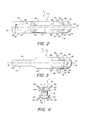
- Fig. 2 is a side view of the surgical anchor of the present invention;
- Fig. 3 is a side view of the surgical anchor shown in Fig. 2, wherein the anchor has been rotated 90° about its longitudinal axis from the position shown in Fig. 2;
- Fig. 4 is a front end view of the surgical anchor shown in Fig. 2;
- Fig. 5 is a view showing a portion of a human femur bone and a portion of a human tibia bone, each having a bone tunnel therethrough, and showing a surgical anchor formed in accordance with the present invention, wherein the anchor has its barbs endosteally engaging the sidewall of the femoral bone tunnel and its rear portion directly attached to an end of a ligament located in the bone tunnels;
- Fig. 6 is a view similar to that of Fig. 1, except that the end of the ligament is shown attached to the rear portion of the surgical anchor by an intervening length of suture-like material;
- Fig. 7 is a view similar to that of Fig. 6, except that the surgical anchor is shown endosteally positioned in the femur;
- Fig. 8 is a view showing a portion of a human femur bone and a portion of a human tibia bone, each having a bone tunnel therethrough, and showing a surgical anchor formed in accordance with the present invention, wherein the anchor has its barbs cortically engaging the surface of the femur bone and its rear portion attached by an intervening length of suture-like material to a bone plug located at an end of a ligament disposed in the bone tunnels;
- Fig. 9 is a view similar to that of Fig. 8, except that the surgical anchor is shown endosteally positioned in the femur; and
- Fig. 10 is a view like that of Fig. 3, except that it shows a threaded
bore 100 added to the front end ofanchor 7. - In order to establish a frame of reference for the following detailed description of the preferred embodiment of the surgical anchor and its method of use, Fig. 1 shows a view of a portion of a
human tibia 1 and a portion of ahuman femur 2 at the point at which they meet to form a human knee joint, generally indicated at 3. Theknee joint 3 is stabilized by a number of connecting tissues (generally not shown in the drawings for purposes of clarity) such as the patellar tendon, the quadriceps femuris tendon, the lateral and medial collateral ligaments, and the anterior and posterior cruciate ligaments. An anterior cruciate ligament graft 4 is shown extending through atibial bone tunnel 5 and into afemural bone tunnel 6. Asurgical anchor 7, formed in accordance with the present invention, is shown attached directly to the end 8 of ligament 4 which is located withinfemoral bone tunnel 6.Anchor 7 extends through theouter end 9 offemoral bone tunnel 6 so as to cortically engage theportion 10 of the outer surface 11 offemur 2 which is located adjacent toouter end 9 offemoral bone tunnel 6. - It is, of course, also to be understood that the repair or replacement of ligaments, tendons and the like may require the endosteal fixation of the anchor to the bone (see Fig. 5); or that the repair material be attached to the anchor by means of an intervening piece of suture or the like (see Figs. 6 and 7, showing such an arrangement in the context of cortical and endosteal fixation, respectively). Furthermore, it is to be understood that the repair or replacement of ligaments, tendons and the like may require the attachment of a bone plug or block to the bone (see Figs. 8 and 9, showing such an arrangement in the context of cortical and endosteal fixation, respectively). It is contemplated that the present anchor will be used in all of these situations, as will hereinafter be discussed in further detail.
- Referring next to Figs. 2, 3 and 4,
surgical anchor 7 comprises abody 14 having alongitudinal axis 15, afront end 16, afront portion 18 adjacentfront end 16, arear end 20, and arear portion 22 adjacentrear end 20. Theouter surface 24 offront portion 18 defines a generallysemi-spherical surface 19, thereby providing the body with a generally forwardly pointed configuration. In the preferred embodiment of the invention,body 14 is formed of 6AL-4V ELI titanium. It is to be understood, however, thatbody 14 could also be formed out of any other suitable, rigid biocompatible metal, or any suitable biocompatible polymeric material, or any suitable bioabsorbable material, all without departure from the present invention. - A bore 26 extends diametrically through the body's
front portion 18 transverse tolongitudinal axis 15.Bore 26 is sized such that a strong suture 28 (see Figs. 1 and 5-9), or some other suitable pulling means, may be threaded therethrough for pullinganchor 7 in a forward axial direction. In addition, tapered grooves (not shown) may extend forwardly from the entries ofbore 26 intobody 14. These grooves, combined with the rounding of the edges of the entries ofbore 26 intobody 14, provide a smooth, substantially continuous surface against which the pulling means (e.g. suture 28) may bear. This feature reduces the chance of breaking the pulling means during the deployment of the anchor. - The
rear portion 22 ofbody 14 includes anopening 30 extending transversely throughbody 14 generally adjacent itsrear end 20.Opening 30 is oriented inbody 14 substantially perpendicular to bore 26 infront portion 18. Further, opening 30 is sized to directly receive either a loop of ligament, tendon or the like (see Figs. 1 and 5) or a loop of suture which is attached to a ligament, tendon or the like (see Figs. 6 and 7) or which is attached to a bone block or plug (see Figs. 8 and 9). - In the embodiment shown in Figs. 2-4,
rear portion 22 is flattened adjacentrear end 20, andopening 30 extends through the flattened section. The edges of the entries of opening 30 into the anchor body are also preferably rounded to minimize the chance of tissue or suture damage or breakage during the anchor insertion process. Further, the flattening ofrear portion 22 relative to the remainder of the anchor provides a pathway for the tissue or suture which will extend rearwardly from opening 30 when the anchor is being deployed within a bone tunnel. This pathway allows the tissue or suture to extend along the flattened sides of the anchor while the anchor is positioned within a bone tunnel so that the tissue or suture is not crushed between the anchor and the sidewall of the bone tunnel. This feature is particularly important in the case where the tissue (or its synthetic substitute) is connected directly to the anchor by looping the tissue through opening 30 (i.e., in the manner shown in Figs. 1 and 5). - A
longitudinal slot 31 extends from opening 30 tofront end 16 ofbody 14.Slot 31 is also oriented substantially perpendicularly to bore 26, and extends across the entire diameter ofbody 14. On account of this construction,body 14 forms a pair of spaced,parallel arms rearmost portion 34 of the body to itsfront end 16.Arms rearmost portion 34 by opposingportions adjacent opening 30.Portions arms arms portions arms front end 16 ofbody 14. The importance of this feature to the overall operation of the device will become more fully apparent in view of the following description. -
Front portion 18 ofbody 14 further includes at least two equally circumferentially spacedlongitudinal channels 38 formed in each of thearms Longitudinal channels 38 all terminate in aforward end 40. Forward ends 40 are all located substantially the same distance fromfront end 16. In the particular structure shown in Figs. 2-4, twolongitudinal channels 38 are formed in the outer surface of each of thearms longitudinal axis 15 ofbody 14. - A plurality of
barbs 44 extend outwardly and rearwardly frombody 14, in spaced circumferential relation to each other. In the preferred embodiment shown in Figs. 2-4, onesuch barb 44 extends outwardly and rearwardly from theforward end 40 of each of thechannels 38 to anouter end 46. Eachouter end 46 is normally located radially outside the periphery of an axial projection of the maximum geometric cross-section ofbody 14, as taken transverse to thelongitudinal axis 15 of the body. At the same time, however,barbs 44 are formed out of an elastically deformable material such that outer ends 46 can be forced radially inwardly so as to be located within the periphery of an axial projection of the maximum geometric cross-section ofbody 14. On account of this construction, whenanchor 7 is inserted longitudinally into an appropriately sized bone tunnel, the outer ends 46 ofbarbs 44 will engage and be deflected inwardly by the sidewall of the bone tunnel. This yieldable engagement ofbarbs 44 with the adjacent bone permits the anchor to be moved along the bone tunnel and then fixed in position, either fully within the bone tunnel (i.e., "endosteally") or at the point where the bone tunnel exits the bone (i.e., "cortically"), as will hereinafter be discussed in further detail. - In the preferred embodiment,
barbs 44 are preferably formed out of a pseudoelastic material of the type disclosed in U.S. Patent No. 4,665,906 entitled "Medical Devices Incorporating SIM Alloy Elements", issued May 19, 1987 to Jervis, which patent is specifically incorporated herein by reference. By way of example, one such pseudoelastic material might be a nickel titanium alloy such as Nitinol, which is available from Flexmedics of Minneapolis, Minnesota, among others. The use of such a material, in combination with the normal orientation of the barbs relative to the anchor body, allows the barbs to "spring back" toward their normal, unstressed condition after the insertion process is complete. - In the preferred embodiment,
barbs 44 are formed as curved arcs extending outwardly frombody 14 when in their normal, unstressed condition. Eachbarb 44 preferably forms an arc of approximately 90 degrees, with the length of the barb being selected so that when one end of the barb is inserted in alongitudinal bore 48 extending forwardly from theforward end 40 of achannel 38, theother end 46 of the barb will extend the desired distance outwardly frombody 14. In this respect it will also be appreciated that the forced fit of the curved barb within thestraight bore 48, combined with the elastic memory of the barb, will tend to maintain the barb in place within the bore. At the same time, the sides ofchannel 38 also help prevent the wire from twisting within the bore. The body ofanchor 7 may also be crimped adjacent thebores 48 so as to further ensure the locking engagement of the barbs withbody 14. - It is to be appreciated that the lengths (and widths) of
barbs 44 andlongitudinal channels 38 are carefully sized relative to one another, such thatbarbs 44 may be fully received inlongitudinal channels 38 to the extent necessary when the barbs are deformed during anchor deployment. - In view of the foregoing, it will be seen that when a pulling means such as suture 28 (see, for example
- Fig. 1) is threaded through
bore 26 and the anchor is thereafter pulled into a bone tunnel using the same, the pulling means will tend to impart a moderate compressive force on the front portions ofarms barbs 44 will engage the sidewall of the bone tunnel. This engagement will force the outer ends 46 of thebarbs 44 inward and rearward, so as to fold the barbs back into their associatedchannels 38. At the same time, this engagement of the barbs with the sidewall of the bone tunnel will have the effect of providing a further, even greater, compressive force to the front portions of thearms arms slot 31 in the anchor, the total amount of force required to deploy the anchor within a bone tunnel will be reduced, as compared to a similar anchor which does not have aslot 31. -
Slot 31 also provides an important additional advantage, in that it makes it very easy to detach the anchor from the tissue or bone plug to which it is attached, even while the anchor is deployed in a bone. Specifically, thelongitudinal slot 31 provides a passageway for the insertion of a sharp tool to sever the tissue or suture which is looped through the anchor'sopening 30. In particular, when the anchor has been set cortically as shown in Figs. 1, 6 and 8, itsfront portion 18 will project out of the far side of the bone tunnel. In that case, a thin cutting tool (not shown) may be passed directly throughslot 31 to engage and sever the tissue (see Fig. 1) or the suture (see Figs. 6 and 8) looped through the anchor'sopening 30. Alternatively, when the anchor has been set endosteally as shown in Figs. 5, 7 and 9, the thin cutting tool may be passed down the bone tunnel and then through theslot 31 so as to engage and sever the tissue (see Fig. 5) or suture (see Figs. 7 and 9) looped through the anchor'sopening 30. Of course, in either case, once the anchor has been released from the repair material which is connected to the rearmost portion of its body, the anchor may be pulled out of the bone tunnel. - It will be understood by those skilled in the art that the dimensions of
anchor 7 will vary according to use. Solely for purposes of illustration, exemplary dimensions of one anchor formed according to the present invention are set forth below:
-
Anchor 7 may be used in a variety of ways. First it will be described in the context of replacing an anterior cruciate ligament 4, where the tissue is to be attached directly to the anchor and the anchor is to be cortically fixed to the femur. More particularly, and looking now at Fig. 1, a length of strong suture orsimilar material 28 is threaded throughbore 26 infront portion 18 ofanchor 7. If desired, the free ends ofsuture 28 may be knotted together so as to form a loop with which to pullanchor 7. A length of ligament or replacement tissue 4 is then attached to the rear portion ofanchor 7. This is accomplished by threading a free end of the ligament or replacement material 4 throughopening 30 in the anchor body, and then fastening it down to the trailing portion of the repair or replacement material (e.g. by suturing) in the manner shown in Fig. 1. Then thesuture 28, which is attached to the front end ofanchor 7, is threaded through the tibial andfemoral bone tunnels Bone tunnels body 14, whereby the anchor'sbarbs 44 may properly engage the sidewalls ofbone tunnels suture 28 are pulled so as to draw anchor 7 (and with it, its trailing ligament 4) throughtibial bone tunnel 5 and intofemoral bone tunnel 6. It will be understood that the generally forwardly pointed configuration of the anchor facilitates its entry into and through the bone tunnels. As the anchor is pulled through the bone tunnels, itsbarbs 44 yieldably engage the sidewalls of the bone tunnels, deflecting inwardly so as to permit the anchor to pass down the bone tunnels. At the same time,arms femoral bone tunnel 6 to the point where at least some, if not all, of itsbarbs 44 pop free ofbone tunnel 6. Thereafter, a pulling force is exerted on theopposite end 53 of ligament 4 to firmly set the barbs into the outer surface layer of the femur so as to effect the desired cortical fixation.Suture 28 may then be pulled free from the set anchor. Finally, theother end 53 of ligament 4, projecting from the outer end 54 oftibial bone tunnel 5, is affixed to the tibia. This may be accomplished by using anotheranchor 7 appropriately attached to ligament 4 or, alternatively, it may be attached to theend 53 oftibia 1 in any one of the many ways well known in the art. By way of example, if theother end 53 of ligament 4 consists solely of soft tissue, the tissue may be attached to the tibia by staples, screws and the like. On the other hand, if theother end 53 of ligament 4 includes a bone block, the block can be attached to the tibia using an interference screw. Such attachments are of the sort well known in the art. - Looking next at Fig. 5, it is also anticipated that
anchor 7 might be used to replace an anterior cruciate ligament 4, where the tissue is attached directly to the anchor and the anchor is endosteally fixed to the femur. In this case the procedure used is identical to the procedure just described with respect to Fig. 1, except that when drawinganchor 7 throughfemoral bone tunnel 6, the pulling onsuture 28 stops when the anchor is still entirely within the femur. In thisway anchor 7 will be endosteally fixed tofemur 2. Again, a slight rearward force is applied to theopposite end 53 of ligament 4 once the anchor is in position within the femur, so as to securely fix the anchor to the femur. Theopposite end 53 of ligament 4 may then be fixed totibia 1 in the manner previously discussed. -
Anchor 7 may also be used to replace an anterior cruciate ligament 4, where the tissue is not attached directly to the anchor. More particularly, and looking now at Fig. 6, the procedure used for cortical fixation is identical to the procedure described above with respect to Fig. 1, except that when attaching ligament 4 toanchor 7, an intervening length ofsuture 50 is used to connect ligament 4 toanchor 7. This is typically done by wrappingsuture 50 several times around the end of the ligament which is being attached toanchor 7, and then loopingsuture 50 through anchor opening 30 before fixing it to ligament 4. - A similar arrangement can also be used to effect an endosteal fixation, as shown in Fig. 7.
- Looking next at Fig. 8, it is also anticipated that
anchor 7 might be used to replace an anterior cruciate ligament, where a bone block is attached to the anchor and the anchor is cortically fixed to the femur. In this case the procedure used is identical to the procedure described above with respect to Fig. 1, except that a length ofsuture 50 is used to connectbone block 52 toanchor 7. This is typically done by passingsuture 50 through one or more holes formed inbone block 52, and then loopingsuture 50 through anchor opening 30 one or more times before making it fast. It will be appreciated that in a fixation of the sort illustrated in Fig. 8, the size ofbone tunnel 6 is coordinated with thesize bone block 52 so as to assure a close fit between the femur and the bone block. At the same time, the size ofbone tunnel 6 is coordinated with the size ofanchor 7 so as to permit proper engagement ofbarbs 44 with the walls of the bone tunnels. In some situations this may call for the use of a steppedbone tunnel 6, such as that shown in Fig. 8. - Looking next at Fig. 9, it is also anticipated that one might use a similar arrangement to effect an endosteal fixation.
- Numerous variations, modifications, adjustments, alterations and alternative uses of the present invention will occur to those skilled in the art in view of the foregoing description of an exemplary and illustrative embodiment of the invention.
- Thus, for example, while in the
preferred embodiment barbs 44 are formed with a normally curved configuration which is then deformed during anchor deployment toward a straight configuration, it is contemplated thatbarbs 44 might be formed with a normally straight configuration which is then deformed during anchor deployment toward a curved configuration. Of course, in such a modification, bores 48 would have to have their orientations altered somewhat so as to normally direct the straight barbs outwardly and rearwardly from the front of the anchor. - Furthermore, means such as a threaded bore 100 (see Fig. 10) might be provided at the front end of the anchor. The presence of such a threaded bore allows the anchor to be securely engaged by a counterpart threaded tool (not shown) for repositioning purposes. This can be particularly important if the anchor must be repositioned after it has been set endosteally in a bone tunnel and the pulling means (i.e., suture 28) has already been removed from the anchor, as it invariably is at the conclusion of the anchor deployment procedure.
- Also, the foregoing description has generally focused on the anchor's barbs being either wholly outside (i.e., "cortical" fixation) or wholly within (i.e., "endosteal" fixation) a bone tunnel. It is to be understood, however, that it is the end of the repair tissue which must be disposed within the bone tunnel, and not necessarily the anchor itself. Hence, it is emphasized that the barbs of the anchor may all be lodged wholly within the bone tunnel, some of the barbs may engage the sidewall of the bone tunnel while others rest upon the surface of the bone adjacent the end of the bone tunnel, or all the barbs may rest against the last described surface, depending upon the surgical procedure involved. Each of these alternatives is considered to be within the scope of the present invention in its broadest aspects.
- It will also be recognized that while the foregoing discussion has generally been directed to the task of attaching tissue (or tissue substitute) to bone, the invention may also be used to attach many different types of elongated objects to many different types of structures, where those structures have a hole extending therethrough.
- For example, the present invention could be used to attach a cable to a wall.
- More particularly, a length of strong cord or similar material might be threaded through the bore in the front portion of the anchor. A length of cable might then be attached to the rear portion of the anchor. This could be accomplished by threading an end of the cable through the opening in the rear portion of the anchor body and then fastening that end down to the trailing portion of the cable. Alternatively, it could also be accomplished by threading a length of cord through the opening in the rear portion of the anchor and thereafter tying the free ends of the cord to the cable. Still further, the cable could simply be looped through the opening in the rear portion of the anchor body so as to be in sliding relation therewith.
- Then the cord attached to the front end of the anchor would be threaded through the hole in the wall. The hole in the wall would be sized so as to be just slightly larger than the maximum diameter of the anchor body so that the anchor's barbs would properly engage the sidewall of the hole. Thereafter, the outer ends of the cord extending through the wall would be pulled so as to draw the anchor along the hole in the wall. As the anchor is pulled along the hole in the wall, its barbs will yieldably engage the sidewall of the hole, deflecting inwardly so as to permit the anchor to pass through the hole. At the same time, the two arms of the anchor will flex inwardly to some extent so as to help reduce the total amount of barb deflection required to allow the anchor to pass along the hole in the wall. As preferred, the anchor could be pulled along the hole so that its barbs pass beyond the far surface of the wall, or the anchor could be pulled along the hole so that its barbs continue to engage the sidewall of the hole. Regardless, a pulling force would thereafter be exerted on the cable so as to firmly set the barbs into the far surface of the wall or into the sidewall of the hole. The cord attached to the front portion of the anchor would then be pulled free from the anchor. In this way, a cable could be attached to a wall.
- Other similar types of attachments could likewise be effected using the present invention.
- It will be further understood that this specification is intended to be illustrative only, and in no way limiting of the invention. The only limitations of the breadth and scope of this invention are set forth in the appended claims.
Claims (12)
Applications Claiming Priority (2)
| Application Number | Priority Date | Filing Date | Title |
|---|---|---|---|
| US08/030,657 US5356413A (en) | 1993-03-12 | 1993-03-12 | Surgical anchor and method for deploying the same |
| US30657 | 1993-03-12 |
Publications (3)
| Publication Number | Publication Date |
|---|---|
| EP0619982A2 true EP0619982A2 (en) | 1994-10-19 |
| EP0619982A3 EP0619982A3 (en) | 1994-12-21 |
| EP0619982B1 EP0619982B1 (en) | 2002-06-12 |
Family
ID=21855308
Family Applications (1)
| Application Number | Title | Priority Date | Filing Date |
|---|---|---|---|
| EP94301686A Expired - Lifetime EP0619982B1 (en) | 1993-03-12 | 1994-03-09 | Surgical anchor |
Country Status (4)
| Country | Link |
|---|---|
| US (1) | US5356413A (en) |
| EP (1) | EP0619982B1 (en) |
| CA (1) | CA2117234C (en) |
| DE (1) | DE69430772T2 (en) |
Cited By (8)
| Publication number | Priority date | Publication date | Assignee | Title |
|---|---|---|---|---|
| EP0688185A1 (en) * | 1994-01-11 | 1995-12-27 | Mitek Surgical Products, Inc. | Surgical anchor and method for deploying the same |
| GB2312376A (en) * | 1996-04-23 | 1997-10-29 | Corifix Limited | A surgical anchor and installation tool |
| WO2000044310A1 (en) * | 1999-01-29 | 2000-08-03 | Smith & Nephew, Inc. | Soft tissue anchor |
| EP1154725A1 (en) * | 1996-07-17 | 2001-11-21 | Orthopedic Designs, Inc. | Surgical fastener assembly |
| EP1269936A2 (en) | 2001-06-29 | 2003-01-02 | Atlantech Medical Devices Limited | A ligament fixation device |
| EP1281376A2 (en) | 2001-07-07 | 2003-02-05 | Atlantech Medical Devices Limited | An anchoring device |
| EP2138122A1 (en) | 2008-06-25 | 2009-12-30 | Abbott Spine | Stabilization system between a sacrum and a lumbar vertebra |
| CN105726109A (en) * | 2016-04-25 | 2016-07-06 | 王京生 | Memory alloy compression fixing pin for fractures of tibial intercondylar eminences |
Families Citing this family (204)
| Publication number | Priority date | Publication date | Assignee | Title |
|---|---|---|---|---|
| US5505735A (en) * | 1993-06-10 | 1996-04-09 | Mitek Surgical Products, Inc. | Surgical anchor and method for using the same |
| US5464425A (en) * | 1994-02-23 | 1995-11-07 | Orthopaedic Biosystems, Ltd. | Medullary suture anchor |
| US5645589A (en) * | 1994-08-22 | 1997-07-08 | Li Medical Technologies, Inc. | Anchor and method for securement into a bore |
| US5843127A (en) * | 1994-08-22 | 1998-12-01 | Le Medical Technologies, Inc. | Fixation device and method for installing same |
| AU3783295A (en) * | 1994-11-16 | 1996-05-23 | Advanced Cardiovascular Systems Inc. | Shape memory locking mechanism for intravascular stent |
| US5643266A (en) * | 1995-06-05 | 1997-07-01 | Li Medical Technologies, Inc. | Method and apparatus for securing ligaments |
| US5702215A (en) * | 1995-06-05 | 1997-12-30 | Li Medical Technologies, Inc. | Retractable fixation device |
| US6117161A (en) * | 1995-06-06 | 2000-09-12 | Li Medical Tecnologies, Inc. | Fastener and fastening method, particularly for fastening sutures to bone |
| AU712207B2 (en) | 1995-06-06 | 1999-10-28 | Raymond Thal | Knotless suture anchor assembly |
| US5569306A (en) * | 1995-06-06 | 1996-10-29 | Thal; Raymond | Knotless suture anchor assembly |
| US5571184A (en) * | 1995-06-07 | 1996-11-05 | Wright Medical Technology, Inc. | Graft fixation device and method of using |
| US5916216A (en) * | 1995-06-07 | 1999-06-29 | Wright Medical Technology, Inc. | Graft fixation devices |
| US5662654A (en) * | 1995-06-14 | 1997-09-02 | Incont, Inc. | Bone anchor, insertion tool and surgical kit employing same |
| US5697931A (en) * | 1995-06-14 | 1997-12-16 | Incont, Inc. | Apparatus and method for laparoscopic urethopexy |
| US5591163A (en) * | 1995-06-14 | 1997-01-07 | Incont, Inc. | Apparatus and method for laparoscopic urethropexy |
| US5643288A (en) * | 1995-06-14 | 1997-07-01 | Incont, Inc. | Apparatus and method for laparoscopic urethropexy |
| US5690649A (en) * | 1995-12-05 | 1997-11-25 | Li Medical Technologies, Inc. | Anchor and anchor installation tool and method |
| US5665111A (en) * | 1996-01-22 | 1997-09-09 | Raymedica, Inc. | Method for anchoring a surgical suture to bone |
| US5681352A (en) * | 1996-03-06 | 1997-10-28 | Kinetikos Medical Incorporated | Method and apparatus for anchoring surgical ties to bone |
| US5718717A (en) | 1996-08-19 | 1998-02-17 | Bonutti; Peter M. | Suture anchor |
| US5741300A (en) * | 1996-09-10 | 1998-04-21 | Li Medical Technologies, Inc. | Surgical anchor and package and cartridge for surgical anchor |
| US8080058B2 (en) * | 2003-04-01 | 2011-12-20 | Depuy Mitek, Inc. | Method and apparatus for fixing a graft in a bone tunnel |
| US5849013A (en) * | 1997-01-14 | 1998-12-15 | Whittaker; Gregory R. | Method and apparatus for fixing a bone block in a bone tunnel |
| US6113604A (en) * | 1997-01-14 | 2000-09-05 | Ethicon, Inc. | Method and apparatus for fixing a graft in a bone tunnel |
| US5707395A (en) | 1997-01-16 | 1998-01-13 | Li Medical Technologies, Inc. | Surgical fastener and method and apparatus for ligament repair |
| US5709708A (en) * | 1997-01-31 | 1998-01-20 | Thal; Raymond | Captured-loop knotless suture anchor assembly |
| IT1299591B1 (en) * | 1997-02-07 | 2000-03-24 | Fabio Conteduca | DEVICE FOR FIXING THE TENDONS USED TO REBUILD THE ANTERIOR CRUCIAL LIGAMENT OF THE FEMORAL HOLE |
| US7066956B2 (en) * | 1997-02-12 | 2006-06-27 | Arthrex, Inc. | Transverse fixation technique for ACL reconstruction using bone-tendon-bone graft |
| US7077863B2 (en) * | 1997-02-12 | 2006-07-18 | Arthrex, Inc. | Transverse fixation technique for ACL reconstruction using bone-tendon-bone graft with loop at end |
| US5918604A (en) | 1997-02-12 | 1999-07-06 | Arthrex, Inc. | Method of loading tendons into the knee |
| CA2303853C (en) | 1997-09-24 | 2007-01-30 | Depuy Orthopaedics, Inc. | Acl fixation pin and method |
| US5871504A (en) * | 1997-10-21 | 1999-02-16 | Eaton; Katulle Koco | Anchor assembly and method for securing ligaments to bone |
| US6066173A (en) * | 1998-01-28 | 2000-05-23 | Ethicon, Inc. | Method and apparatus for fixing a graft in a bone tunnel |
| US6045551A (en) | 1998-02-06 | 2000-04-04 | Bonutti; Peter M. | Bone suture |
| US6146406A (en) | 1998-02-12 | 2000-11-14 | Smith & Nephew, Inc. | Bone anchor |
| US5964764A (en) * | 1998-03-24 | 1999-10-12 | Hugh S. West, Jr. | Apparatus and methods for mounting a ligament graft to a bone |
| WO1999059488A1 (en) * | 1998-05-21 | 1999-11-25 | Chan Kwan Ho | Apparatus and method for ligament fixation |
| US6482210B1 (en) * | 1998-11-12 | 2002-11-19 | Orthopaedic Biosystems, Ltd., Inc. | Soft tissue/ligament to bone fixation device with inserter |
| US8343186B2 (en) | 2004-04-06 | 2013-01-01 | Arthrex, Inc. | Fully threaded suture anchor with transverse anchor pin |
| US9521999B2 (en) | 2005-09-13 | 2016-12-20 | Arthrex, Inc. | Fully-threaded bioabsorbable suture anchor |
| US8821541B2 (en) | 1999-02-02 | 2014-09-02 | Arthrex, Inc. | Suture anchor with insert-molded rigid member |
| US6152928A (en) | 1999-03-02 | 2000-11-28 | Ethicon, Inc. | Ligament fixation device and method |
| US6159179A (en) | 1999-03-12 | 2000-12-12 | Simonson; Robert E. | Cannula and sizing and insertion method |
| US6689153B1 (en) | 1999-04-16 | 2004-02-10 | Orthopaedic Biosystems Ltd, Inc. | Methods and apparatus for a coated anchoring device and/or suture |
| US6752830B1 (en) * | 1999-07-20 | 2004-06-22 | Ethicon, Inc. | Apparatus and method for reconstructing a ligament |
| FR2897259B1 (en) | 2006-02-15 | 2008-05-09 | Ldr Medical Soc Par Actions Si | INTERSOMATIC TRANSFORAMINAL CAGE WITH INTERBREBAL FUSION GRAFT AND CAGE IMPLANTATION INSTRUMENT |
| US6368343B1 (en) | 2000-03-13 | 2002-04-09 | Peter M. Bonutti | Method of using ultrasonic vibration to secure body tissue |
| US6447516B1 (en) | 1999-08-09 | 2002-09-10 | Peter M. Bonutti | Method of securing tissue |
| AU6532500A (en) * | 1999-08-10 | 2001-03-05 | Ethicon Inc. | Apparatus and method for reconstructing a ligament |
| US20020198551A1 (en) * | 1999-11-16 | 2002-12-26 | Grant Kevin Lee | Endoscopic tissue separator surgical device |
| US6635073B2 (en) | 2000-05-03 | 2003-10-21 | Peter M. Bonutti | Method of securing body tissue |
| US7993368B2 (en) | 2003-03-13 | 2011-08-09 | C.R. Bard, Inc. | Suture clips, delivery devices and methods |
| JP2004514462A (en) | 2000-03-03 | 2004-05-20 | シー・アール・バード・インク | Tissue adhesion device for endoscope with multiple suction ports |
| US6599289B1 (en) | 2000-03-10 | 2003-07-29 | Smith & Nephew, Inc. | Graft anchor |
| US8105351B2 (en) | 2001-05-18 | 2012-01-31 | C.R. Bard, Inc. | Method of promoting tissue adhesion |
| ES2435094T3 (en) | 2000-05-19 | 2013-12-18 | C.R. Bard, Inc. | Device and method of tissue capture and suturing |
| US6623524B2 (en) | 2000-06-09 | 2003-09-23 | Arthrex, Inc. | Method for anterior cruciate ligament reconstruction using cross-pin implant with eyelet |
| US6325804B1 (en) | 2000-06-28 | 2001-12-04 | Ethicon, Inc. | Method for fixing a graft in a bone tunnel |
| JP2004516040A (en) | 2000-06-30 | 2004-06-03 | リトラン、スティーブン | Multi-shaft coupling device and method |
| US6447546B1 (en) | 2000-08-11 | 2002-09-10 | Dale G. Bramlet | Apparatus and method for fusing opposing spinal vertebrae |
| US6878166B2 (en) | 2000-08-28 | 2005-04-12 | Ron Clark | Method and implant for securing ligament replacement into the knee |
| US7530999B2 (en) * | 2000-08-28 | 2009-05-12 | Biomet Sports Medicine, Llc | Method and implant for securing ligament replacement into the knee |
| US7166073B2 (en) | 2000-09-29 | 2007-01-23 | Stephen Ritland | Method and device for microsurgical intermuscular spinal surgery |
| US6692434B2 (en) | 2000-09-29 | 2004-02-17 | Stephen Ritland | Method and device for retractor for microsurgical intermuscular lumbar arthrodesis |
| US6887259B2 (en) * | 2000-10-18 | 2005-05-03 | Depuy Mitek, Inc. | Suture anchor system and method of use |
| US6641596B1 (en) * | 2000-10-18 | 2003-11-04 | Ethicon, Inc. | Knotless bioabsorbable suture anchor system and method |
| US6527795B1 (en) | 2000-10-18 | 2003-03-04 | Ethicon, Inc. | Knotless suture anchor system and method of use |
| US6929606B2 (en) | 2001-01-29 | 2005-08-16 | Depuy Spine, Inc. | Retractor and method for spinal pedicle screw placement |
| EP1355578A1 (en) * | 2001-01-29 | 2003-10-29 | Stephen Ritland | Retractor and method for spinal pedicle screw placement |
| US6517546B2 (en) | 2001-03-13 | 2003-02-11 | Gregory R. Whittaker | Method and apparatus for fixing a graft in a bone tunnel |
| US7594917B2 (en) | 2001-03-13 | 2009-09-29 | Ethicon, Inc. | Method and apparatus for fixing a graft in a bone tunnel |
| US7195642B2 (en) | 2001-03-13 | 2007-03-27 | Mckernan Daniel J | Method and apparatus for fixing a graft in a bone tunnel |
| FR2824261B1 (en) | 2001-05-04 | 2004-05-28 | Ldr Medical | INTERVERTEBRAL DISC PROSTHESIS AND IMPLEMENTATION METHOD AND TOOLS |
| FR2827156B1 (en) | 2001-07-13 | 2003-11-14 | Ldr Medical | VERTEBRAL CAGE DEVICE WITH MODULAR FASTENING |
| US8512376B2 (en) * | 2002-08-30 | 2013-08-20 | Arthrex, Inc. | Method and apparatus for internal fixation of an acromioclavicular joint dislocation of the shoulder |
| US7207992B2 (en) | 2001-09-28 | 2007-04-24 | Stephen Ritland | Connection rod for screw or hook polyaxial system and method of use |
| US7520898B2 (en) * | 2001-10-01 | 2009-04-21 | Scandius Biomedical, Inc. | Apparatus and method for reconstructing a ligament |
| US6712849B2 (en) * | 2001-10-01 | 2004-03-30 | Scandius Biomedical, Inc. | Apparatus and method for reconstructing a ligament |
| US7824410B2 (en) | 2001-10-30 | 2010-11-02 | Depuy Spine, Inc. | Instruments and methods for minimally invasive spine surgery |
| US7008431B2 (en) | 2001-10-30 | 2006-03-07 | Depuy Spine, Inc. | Configured and sized cannula |
| US6916330B2 (en) * | 2001-10-30 | 2005-07-12 | Depuy Spine, Inc. | Non cannulated dilators |
| US6719765B2 (en) | 2001-12-03 | 2004-04-13 | Bonutti 2003 Trust-A | Magnetic suturing system and method |
| DE20120467U1 (en) * | 2001-12-18 | 2002-04-18 | Biotissue Technologies Ag | Fastening element for tissue, cartilage and / or bone material |
| US7033364B1 (en) * | 2002-01-31 | 2006-04-25 | Arthrotek, Inc. | Apparatus and method for manipulating a flexible strand and soft tissue replacement during surgery |
| US7713300B2 (en) * | 2002-01-31 | 2010-05-11 | Biomet Sports Medicince, LLC | Apparatus and method for manipulating a flexible strand and soft tissue replacement during surgery |
| US20060206206A1 (en) | 2003-06-06 | 2006-09-14 | Peyman Gholam A | Intraocular telescope |
| CA2475200C (en) * | 2002-02-20 | 2011-02-15 | Stephen Ritland | Pedicle screw connector apparatus and method |
| US6966910B2 (en) | 2002-04-05 | 2005-11-22 | Stephen Ritland | Dynamic fixation device and method of use |
| EP1585427B1 (en) * | 2002-05-08 | 2012-04-11 | Stephen Ritland | Dynamic fixation device |
| ES2702605T3 (en) | 2002-09-06 | 2019-03-04 | Bard Inc C R | Endoscope and integrated accessory treatment device |
| FR2846550B1 (en) | 2002-11-05 | 2006-01-13 | Ldr Medical | INTERVERTEBRAL DISC PROSTHESIS |
| JP4598760B2 (en) | 2003-02-25 | 2010-12-15 | リットランド、ステファン | ADJUSTING ROD AND CONNECTOR DEVICE, AND ITS USING METHOD |
| JP4565218B2 (en) | 2003-05-16 | 2010-10-20 | シー・アール・バード・インク | Single intubation multiple-time suture endoscopic suture system |
| WO2004110247A2 (en) | 2003-05-22 | 2004-12-23 | Stephen Ritland | Intermuscular guide for retractor insertion and method of use |
| US7341592B1 (en) | 2003-10-15 | 2008-03-11 | Biomet Sports Medicine, Inc. | Method and apparatus for graft fixation |
| US7896917B2 (en) | 2003-10-15 | 2011-03-01 | Biomet Sports Medicine, Llc | Method and apparatus for graft fixation |
| ES2547532T3 (en) | 2004-02-04 | 2015-10-07 | Ldr Medical | Intervertebral disc prosthesis |
| FR2865629B1 (en) | 2004-02-04 | 2007-01-26 | Ldr Medical | INTERVERTEBRAL DISC PROSTHESIS |
| US7608092B1 (en) | 2004-02-20 | 2009-10-27 | Biomet Sports Medicince, LLC | Method and apparatus for performing meniscus repair |
| US20050245932A1 (en) * | 2004-04-16 | 2005-11-03 | Fanton Gary S | Apparatus and methods for securing tissue to bone |
| US7938847B2 (en) * | 2006-01-04 | 2011-05-10 | Tornier, Inc. | Ring cinch assembly to attach bone to tissue |
| JP4879166B2 (en) * | 2004-04-22 | 2012-02-22 | スキャンディウス・バイオメディカル・インコーポレーテッド | Apparatus and method for reconstructing a ligament |
| FR2869528B1 (en) | 2004-04-28 | 2007-02-02 | Ldr Medical | INTERVERTEBRAL DISC PROSTHESIS |
| US7500983B1 (en) | 2004-06-09 | 2009-03-10 | Biomet Sports Medicine, Llc | Apparatus for soft tissue attachment |
| US8109965B2 (en) | 2004-06-09 | 2012-02-07 | Biomet Sports Medicine, LLP | Method and apparatus for soft tissue fixation |
| US7819898B2 (en) | 2004-06-09 | 2010-10-26 | Biomet Sports Medicine, Llc | Method and apparatus for soft tissue fixation |
| US7695503B1 (en) | 2004-06-09 | 2010-04-13 | Biomet Sports Medicine, Llc | Method and apparatus for soft tissue attachment |
| US8002778B1 (en) * | 2004-06-28 | 2011-08-23 | Biomet Sports Medicine, Llc | Crosspin and method for inserting the same during soft ligament repair |
| US7909843B2 (en) | 2004-06-30 | 2011-03-22 | Thompson Surgical Instruments, Inc. | Elongateable surgical port and dilator |
| US7455639B2 (en) | 2004-09-20 | 2008-11-25 | Stephen Ritland | Opposing parallel bladed retractor and method of use |
| US7905903B2 (en) | 2006-02-03 | 2011-03-15 | Biomet Sports Medicine, Llc | Method for tissue fixation |
| US8137382B2 (en) | 2004-11-05 | 2012-03-20 | Biomet Sports Medicine, Llc | Method and apparatus for coupling anatomical features |
| US7658751B2 (en) | 2006-09-29 | 2010-02-09 | Biomet Sports Medicine, Llc | Method for implanting soft tissue |
| US7909851B2 (en) | 2006-02-03 | 2011-03-22 | Biomet Sports Medicine, Llc | Soft tissue repair device and associated methods |
| US7749250B2 (en) | 2006-02-03 | 2010-07-06 | Biomet Sports Medicine, Llc | Soft tissue repair assembly and associated method |
| US20060189993A1 (en) | 2004-11-09 | 2006-08-24 | Arthrotek, Inc. | Soft tissue conduit device |
| US9801708B2 (en) | 2004-11-05 | 2017-10-31 | Biomet Sports Medicine, Llc | Method and apparatus for coupling soft tissue to a bone |
| US7905904B2 (en) | 2006-02-03 | 2011-03-15 | Biomet Sports Medicine, Llc | Soft tissue repair device and associated methods |
| US9017381B2 (en) | 2007-04-10 | 2015-04-28 | Biomet Sports Medicine, Llc | Adjustable knotless loops |
| US8088130B2 (en) | 2006-02-03 | 2012-01-03 | Biomet Sports Medicine, Llc | Method and apparatus for coupling soft tissue to a bone |
| US7857830B2 (en) | 2006-02-03 | 2010-12-28 | Biomet Sports Medicine, Llc | Soft tissue repair and conduit device |
| US8118836B2 (en) | 2004-11-05 | 2012-02-21 | Biomet Sports Medicine, Llc | Method and apparatus for coupling soft tissue to a bone |
| US8361113B2 (en) | 2006-02-03 | 2013-01-29 | Biomet Sports Medicine, Llc | Method and apparatus for coupling soft tissue to a bone |
| US8840645B2 (en) | 2004-11-05 | 2014-09-23 | Biomet Sports Medicine, Llc | Method and apparatus for coupling soft tissue to a bone |
| US8298262B2 (en) | 2006-02-03 | 2012-10-30 | Biomet Sports Medicine, Llc | Method for tissue fixation |
| US8303604B2 (en) | 2004-11-05 | 2012-11-06 | Biomet Sports Medicine, Llc | Soft tissue repair device and method |
| US8128658B2 (en) | 2004-11-05 | 2012-03-06 | Biomet Sports Medicine, Llc | Method and apparatus for coupling soft tissue to bone |
| US8998949B2 (en) | 2004-11-09 | 2015-04-07 | Biomet Sports Medicine, Llc | Soft tissue conduit device |
| FR2879436B1 (en) | 2004-12-22 | 2007-03-09 | Ldr Medical | INTERVERTEBRAL DISC PROSTHESIS |
| CA2615497C (en) | 2005-07-19 | 2014-03-25 | Stephen Ritland | Rod extension for extending fusion construct |
| FR2891135B1 (en) | 2005-09-23 | 2008-09-12 | Ldr Medical Sarl | INTERVERTEBRAL DISC PROSTHESIS |
| FR2893838B1 (en) | 2005-11-30 | 2008-08-08 | Ldr Medical Soc Par Actions Si | PROSTHESIS OF INTERVERTEBRAL DISC AND INSTRUMENTATION OF INSERTION OF THE PROSTHESIS BETWEEN VERTEBRATES |
| US8435292B2 (en) | 2005-12-20 | 2013-05-07 | Depuy Mitek, Inc. | Methods for ligament reconstruction |
| US20070162123A1 (en) * | 2005-12-20 | 2007-07-12 | Whittaker Gregory R | Materials and methods for ligament reconstruction |
| US8562645B2 (en) | 2006-09-29 | 2013-10-22 | Biomet Sports Medicine, Llc | Method and apparatus for forming a self-locking adjustable loop |
| US9078644B2 (en) | 2006-09-29 | 2015-07-14 | Biomet Sports Medicine, Llc | Fracture fixation device |
| US8652171B2 (en) | 2006-02-03 | 2014-02-18 | Biomet Sports Medicine, Llc | Method and apparatus for soft tissue fixation |
| US8562647B2 (en) | 2006-09-29 | 2013-10-22 | Biomet Sports Medicine, Llc | Method and apparatus for securing soft tissue to bone |
| US9149267B2 (en) | 2006-02-03 | 2015-10-06 | Biomet Sports Medicine, Llc | Method and apparatus for coupling soft tissue to a bone |
| US8251998B2 (en) | 2006-08-16 | 2012-08-28 | Biomet Sports Medicine, Llc | Chondral defect repair |
| US7959650B2 (en) | 2006-09-29 | 2011-06-14 | Biomet Sports Medicine, Llc | Adjustable knotless loops |
| US8801783B2 (en) | 2006-09-29 | 2014-08-12 | Biomet Sports Medicine, Llc | Prosthetic ligament system for knee joint |
| US8968364B2 (en) | 2006-02-03 | 2015-03-03 | Biomet Sports Medicine, Llc | Method and apparatus for fixation of an ACL graft |
| US11311287B2 (en) | 2006-02-03 | 2022-04-26 | Biomet Sports Medicine, Llc | Method for tissue fixation |
| US9538998B2 (en) | 2006-02-03 | 2017-01-10 | Biomet Sports Medicine, Llc | Method and apparatus for fracture fixation |
| US8574235B2 (en) | 2006-02-03 | 2013-11-05 | Biomet Sports Medicine, Llc | Method for trochanteric reattachment |
| US8771352B2 (en) | 2011-05-17 | 2014-07-08 | Biomet Sports Medicine, Llc | Method and apparatus for tibial fixation of an ACL graft |
| US11259792B2 (en) | 2006-02-03 | 2022-03-01 | Biomet Sports Medicine, Llc | Method and apparatus for coupling anatomical features |
| US8936621B2 (en) | 2006-02-03 | 2015-01-20 | Biomet Sports Medicine, Llc | Method and apparatus for forming a self-locking adjustable loop |
| US10517587B2 (en) | 2006-02-03 | 2019-12-31 | Biomet Sports Medicine, Llc | Method and apparatus for forming a self-locking adjustable loop |
| US9271713B2 (en) | 2006-02-03 | 2016-03-01 | Biomet Sports Medicine, Llc | Method and apparatus for tensioning a suture |
| US8506597B2 (en) | 2011-10-25 | 2013-08-13 | Biomet Sports Medicine, Llc | Method and apparatus for interosseous membrane reconstruction |
| US8652172B2 (en) | 2006-02-03 | 2014-02-18 | Biomet Sports Medicine, Llc | Flexible anchors for tissue fixation |
| US8597327B2 (en) | 2006-02-03 | 2013-12-03 | Biomet Manufacturing, Llc | Method and apparatus for sternal closure |
| US7828820B2 (en) | 2006-03-21 | 2010-11-09 | Biomet Sports Medicine, Llc | Method and apparatuses for securing suture |
| AU2007227351A1 (en) | 2006-03-22 | 2007-09-27 | C2M Medical, Inc. | Suture passer devices and uses thereof |
| US9005220B2 (en) | 2006-04-04 | 2015-04-14 | C.R. Bard, Inc. | Suturing devices and methods with energy emitting elements |
| US8852250B2 (en) * | 2006-05-18 | 2014-10-07 | Linvatec Corporation | Graft fixation implant |
| US7959564B2 (en) | 2006-07-08 | 2011-06-14 | Stephen Ritland | Pedicle seeker and retractor, and methods of use |
| US8672969B2 (en) | 2006-09-29 | 2014-03-18 | Biomet Sports Medicine, Llc | Fracture fixation device |
| US8500818B2 (en) | 2006-09-29 | 2013-08-06 | Biomet Manufacturing, Llc | Knee prosthesis assembly with ligament link |
| US9918826B2 (en) | 2006-09-29 | 2018-03-20 | Biomet Sports Medicine, Llc | Scaffold for spring ligament repair |
| US11259794B2 (en) | 2006-09-29 | 2022-03-01 | Biomet Sports Medicine, Llc | Method for implanting soft tissue |
| US8491595B2 (en) | 2006-10-30 | 2013-07-23 | Depuy Mitek, Llc | Methods and devices for ligament repair |
| US8465546B2 (en) | 2007-02-16 | 2013-06-18 | Ldr Medical | Intervertebral disc prosthesis insertion assemblies |
| EP2120753B1 (en) * | 2007-03-05 | 2022-09-28 | Tornier, Inc. | Tack anchor systems |
| US8147546B2 (en) | 2007-03-13 | 2012-04-03 | Biomet Sports Medicine, Llc | Method and apparatus for graft fixation |
| FR2916956B1 (en) | 2007-06-08 | 2012-12-14 | Ldr Medical | INTERSOMATIC CAGE, INTERVERTEBRAL PROSTHESIS, ANCHORING DEVICE AND IMPLANTATION INSTRUMENTATION |
| AU2009200864A1 (en) * | 2008-02-29 | 2009-09-17 | Robert J. Medoff | Method and apparatus for articular scapholunate reconstruction |
| CA2738426C (en) | 2008-09-29 | 2016-03-15 | C.R. Bard, Inc. | Endoscopic suturing device |
| US20100305710A1 (en) | 2009-05-28 | 2010-12-02 | Biomet Manufacturing Corp. | Knee Prosthesis |
| BR112012005663A2 (en) | 2009-09-17 | 2021-07-27 | Synthes Gmbh | intervertebral implant with expandable bone fixation limbs |
| US8449612B2 (en) * | 2009-11-16 | 2013-05-28 | Arthrocare Corporation | Graft pulley and methods of use |
| WO2011060437A1 (en) | 2009-11-16 | 2011-05-19 | Tornier, Inc. | Bone implant with convertible suture attachment |
| US20110118838A1 (en) * | 2009-11-16 | 2011-05-19 | George Delli-Santi | Graft pulley and methods of use |
| US9833331B2 (en) | 2009-12-31 | 2017-12-05 | Ldr Medical | Anchoring device and system for an intervertebral implant, intervertebral implant and implantation instrument |
| CA2800091A1 (en) | 2010-05-26 | 2011-12-01 | J. Christopher Flaherty | Implantable prostheses |
| EP2685940A4 (en) * | 2011-03-14 | 2015-01-21 | Topsfield Medical Gmbh | Implantable glenoid prostheses |
| US8998925B2 (en) | 2011-06-20 | 2015-04-07 | Rdc Holdings, Llc | Fixation system for orthopedic devices |
| WO2012177759A1 (en) | 2011-06-20 | 2012-12-27 | Rdc Holdings, Llc | System and method for repairing joints |
| US8617176B2 (en) | 2011-08-24 | 2013-12-31 | Depuy Mitek, Llc | Cross pinning guide devices and methods |
| US8834523B2 (en) * | 2011-09-29 | 2014-09-16 | Smith & Nephew, Inc. | Attachment device to attach tissue graft |
| US9023082B2 (en) * | 2011-10-21 | 2015-05-05 | Depuy Mitek, Llc | Suture anchor assembly with compressible distal tip |
| US9277911B2 (en) | 2011-10-21 | 2016-03-08 | Depuy Mitek, Llc | Suture anchor system with compressible distal tip |
| US9357991B2 (en) | 2011-11-03 | 2016-06-07 | Biomet Sports Medicine, Llc | Method and apparatus for stitching tendons |
| US9370350B2 (en) | 2011-11-10 | 2016-06-21 | Biomet Sports Medicine, Llc | Apparatus for coupling soft tissue to a bone |
| US9381013B2 (en) | 2011-11-10 | 2016-07-05 | Biomet Sports Medicine, Llc | Method for coupling soft tissue to a bone |
| US9357992B2 (en) | 2011-11-10 | 2016-06-07 | Biomet Sports Medicine, Llc | Method for coupling soft tissue to a bone |
| US9173657B2 (en) | 2011-12-15 | 2015-11-03 | Ethicon Endo-Surgery, Inc. | Devices and methods for endoluminal plication |
| US9119615B2 (en) | 2011-12-15 | 2015-09-01 | Ethicon Endo-Surgery, Inc. | Devices and methods for endoluminal plication |
| US9259217B2 (en) | 2012-01-03 | 2016-02-16 | Biomet Manufacturing, Llc | Suture Button |
| FR2987256B1 (en) | 2012-02-24 | 2014-08-08 | Ldr Medical | ANCHORING DEVICE FOR INTERVERTEBRAL IMPLANT, INTERVERTEBRAL IMPLANT AND IMPLANTATION INSTRUMENTATION |
| US8992547B2 (en) | 2012-03-21 | 2015-03-31 | Ethicon Endo-Surgery, Inc. | Methods and devices for creating tissue plications |
| US9757119B2 (en) | 2013-03-08 | 2017-09-12 | Biomet Sports Medicine, Llc | Visual aid for identifying suture limbs arthroscopically |
| US9918827B2 (en) | 2013-03-14 | 2018-03-20 | Biomet Sports Medicine, Llc | Scaffold for spring ligament repair |
| US10016192B2 (en) | 2013-06-14 | 2018-07-10 | Tornier, Inc. | Suture for connecting a human or animal tissue, soft anchor and method for attaching a tissue to a bone |
| US10136886B2 (en) | 2013-12-20 | 2018-11-27 | Biomet Sports Medicine, Llc | Knotless soft tissue devices and techniques |
| WO2015120165A1 (en) | 2014-02-05 | 2015-08-13 | Marino James F | Anchor devices and methods of use |
| US9615822B2 (en) | 2014-05-30 | 2017-04-11 | Biomet Sports Medicine, Llc | Insertion tools and method for soft anchor |
| US9700291B2 (en) | 2014-06-03 | 2017-07-11 | Biomet Sports Medicine, Llc | Capsule retractor |
| US10039543B2 (en) | 2014-08-22 | 2018-08-07 | Biomet Sports Medicine, Llc | Non-sliding soft anchor |
| US9955980B2 (en) | 2015-02-24 | 2018-05-01 | Biomet Sports Medicine, Llc | Anatomic soft tissue repair |
| US9974534B2 (en) | 2015-03-31 | 2018-05-22 | Biomet Sports Medicine, Llc | Suture anchor with soft anchor of electrospun fibers |
| CN108523977A (en) * | 2018-05-31 | 2018-09-14 | 徐立虎 | A kind of bone block fixing device and medical treatment device |
Citations (6)
| Publication number | Priority date | Publication date | Assignee | Title |
|---|---|---|---|---|
| GB567697A (en) * | 1943-09-07 | 1945-02-27 | Martin James | Improvements in and relating to hinge pins, retainer pins and the like provided withself-locking means |
| GB688518A (en) * | 1950-05-19 | 1953-03-11 | United Carr Fastener Corp | Improvements in and relating to fastener devices |
| US4260122A (en) * | 1978-02-17 | 1981-04-07 | Johann Fiala | Clamping wall plug for elongated bodies |
| EP0376641A1 (en) * | 1988-12-27 | 1990-07-04 | E. Marlowe Goble | Ligament anchor system |
| US5176682A (en) * | 1992-06-01 | 1993-01-05 | Chow James C Y | Surgical implement |
| WO1993000866A2 (en) * | 1991-07-11 | 1993-01-21 | Legrand Jean Jacques | Device for reinforcing a ligament transplant during reconstructive surgery |
Family Cites Families (4)
| Publication number | Priority date | Publication date | Assignee | Title |
|---|---|---|---|---|
| US4997433A (en) * | 1990-01-16 | 1991-03-05 | Marlowe Goble E | Endosteal fixation stud and system |
| US5236445A (en) * | 1990-07-02 | 1993-08-17 | American Cyanamid Company | Expandable bone anchor and method of anchoring a suture to a bone |
| US5147362A (en) * | 1991-04-08 | 1992-09-15 | Marlowe Goble E | Endosteal ligament fixation device |
| US5156616A (en) * | 1992-02-10 | 1992-10-20 | Meadows Bruce F | Apparatus and method for suture attachment |
-
1993
- 1993-03-12 US US08/030,657 patent/US5356413A/en not_active Expired - Lifetime
-
1994
- 1994-03-08 CA CA002117234A patent/CA2117234C/en not_active Expired - Fee Related
- 1994-03-09 DE DE69430772T patent/DE69430772T2/en not_active Expired - Fee Related
- 1994-03-09 EP EP94301686A patent/EP0619982B1/en not_active Expired - Lifetime
Patent Citations (6)
| Publication number | Priority date | Publication date | Assignee | Title |
|---|---|---|---|---|
| GB567697A (en) * | 1943-09-07 | 1945-02-27 | Martin James | Improvements in and relating to hinge pins, retainer pins and the like provided withself-locking means |
| GB688518A (en) * | 1950-05-19 | 1953-03-11 | United Carr Fastener Corp | Improvements in and relating to fastener devices |
| US4260122A (en) * | 1978-02-17 | 1981-04-07 | Johann Fiala | Clamping wall plug for elongated bodies |
| EP0376641A1 (en) * | 1988-12-27 | 1990-07-04 | E. Marlowe Goble | Ligament anchor system |
| WO1993000866A2 (en) * | 1991-07-11 | 1993-01-21 | Legrand Jean Jacques | Device for reinforcing a ligament transplant during reconstructive surgery |
| US5176682A (en) * | 1992-06-01 | 1993-01-05 | Chow James C Y | Surgical implement |
Cited By (13)
| Publication number | Priority date | Publication date | Assignee | Title |
|---|---|---|---|---|
| EP0688185A4 (en) * | 1994-01-11 | 1996-09-18 | Mitek Surgical Prod | Surgical anchor and method for deploying the same |
| EP0688185A1 (en) * | 1994-01-11 | 1995-12-27 | Mitek Surgical Products, Inc. | Surgical anchor and method for deploying the same |
| US6695844B2 (en) | 1996-03-13 | 2004-02-24 | Orthopedic Designs, Inc. | Surgical fastener assembly |
| GB2312376A (en) * | 1996-04-23 | 1997-10-29 | Corifix Limited | A surgical anchor and installation tool |
| EP1154725A1 (en) * | 1996-07-17 | 2001-11-21 | Orthopedic Designs, Inc. | Surgical fastener assembly |
| EP1154725A4 (en) * | 1996-07-17 | 2003-01-02 | Orthopedic Designs Inc | Surgical fastener assembly |
| WO2000044310A1 (en) * | 1999-01-29 | 2000-08-03 | Smith & Nephew, Inc. | Soft tissue anchor |
| AU767853B2 (en) * | 1999-01-29 | 2003-11-27 | Smith & Nephew, Inc. | Soft tissue anchor |
| EP1269936A2 (en) | 2001-06-29 | 2003-01-02 | Atlantech Medical Devices Limited | A ligament fixation device |
| EP1281376A2 (en) | 2001-07-07 | 2003-02-05 | Atlantech Medical Devices Limited | An anchoring device |
| US6736847B2 (en) | 2001-07-07 | 2004-05-18 | Arthrocare Corporation | Anchoring device |
| EP2138122A1 (en) | 2008-06-25 | 2009-12-30 | Abbott Spine | Stabilization system between a sacrum and a lumbar vertebra |
| CN105726109A (en) * | 2016-04-25 | 2016-07-06 | 王京生 | Memory alloy compression fixing pin for fractures of tibial intercondylar eminences |
Also Published As
| Publication number | Publication date |
|---|---|
| EP0619982B1 (en) | 2002-06-12 |
| CA2117234C (en) | 2005-05-17 |
| CA2117234A1 (en) | 1994-09-13 |
| US5356413A (en) | 1994-10-18 |
| DE69430772D1 (en) | 2002-07-18 |
| EP0619982A3 (en) | 1994-12-21 |
| DE69430772T2 (en) | 2003-02-20 |
Similar Documents
| Publication | Publication Date | Title |
|---|---|---|
| EP0619982B1 (en) | Surgical anchor | |
| EP0688185B1 (en) | Surgical anchor | |
| US5571104A (en) | Surgical anchor and method for using the same | |
| US9907646B2 (en) | Femoral fixation | |
| US8100969B2 (en) | Methods for anchoring autologous or artificial tendon grafts using first and second bone anchors | |
| US7901456B2 (en) | Expanding ligament graft fixation system method | |
| EP1006934B1 (en) | Apparatus for anchoring autologous or artificial tendon grafts in bone | |
| US8496705B2 (en) | Method of anchoring autologous or artificial tendon grafts in bone |
Legal Events
| Date | Code | Title | Description |
|---|---|---|---|
| PUAI | Public reference made under article 153(3) epc to a published international application that has entered the european phase |
Free format text: ORIGINAL CODE: 0009012 |
|
| AK | Designated contracting states |
Kind code of ref document: A2 Designated state(s): CH DE FR GB IT LI |
|
| PUAL | Search report despatched |
Free format text: ORIGINAL CODE: 0009013 |
|
| AK | Designated contracting states |
Kind code of ref document: A3 Designated state(s): CH DE FR GB IT LI |
|
| 17P | Request for examination filed |
Effective date: 19950616 |
|
| 17Q | First examination report despatched |
Effective date: 19990128 |
|
| GRAG | Despatch of communication of intention to grant |
Free format text: ORIGINAL CODE: EPIDOS AGRA |
|
| GRAG | Despatch of communication of intention to grant |
Free format text: ORIGINAL CODE: EPIDOS AGRA |
|
| GRAH | Despatch of communication of intention to grant a patent |
Free format text: ORIGINAL CODE: EPIDOS IGRA |
|
| GRAH | Despatch of communication of intention to grant a patent |
Free format text: ORIGINAL CODE: EPIDOS IGRA |
|
| GRAA | (expected) grant |
Free format text: ORIGINAL CODE: 0009210 |
|
| AK | Designated contracting states |
Kind code of ref document: B1 Designated state(s): CH DE FR GB IT LI |
|
| PG25 | Lapsed in a contracting state [announced via postgrant information from national office to epo] |
Ref country code: LI Free format text: LAPSE BECAUSE OF FAILURE TO SUBMIT A TRANSLATION OF THE DESCRIPTION OR TO PAY THE FEE WITHIN THE PRESCRIBED TIME-LIMIT Effective date: 20020612 Ref country code: CH Free format text: LAPSE BECAUSE OF FAILURE TO SUBMIT A TRANSLATION OF THE DESCRIPTION OR TO PAY THE FEE WITHIN THE PRESCRIBED TIME-LIMIT Effective date: 20020612 |
|
| REG | Reference to a national code |
Ref country code: GB Ref legal event code: FG4D |
|
| REG | Reference to a national code |
Ref country code: CH Ref legal event code: EP |
|
| REF | Corresponds to: |
Ref document number: 69430772 Country of ref document: DE Date of ref document: 20020718 |
|
| ET | Fr: translation filed | ||
| REG | Reference to a national code |
Ref country code: CH Ref legal event code: PL |
|
| PLBE | No opposition filed within time limit |
Free format text: ORIGINAL CODE: 0009261 |
|
| STAA | Information on the status of an ep patent application or granted ep patent |
Free format text: STATUS: NO OPPOSITION FILED WITHIN TIME LIMIT |
|
| 26N | No opposition filed |
Effective date: 20030313 |
|
| PGFP | Annual fee paid to national office [announced via postgrant information from national office to epo] |
Ref country code: GB Payment date: 20090304 Year of fee payment: 16 |
|
| PGFP | Annual fee paid to national office [announced via postgrant information from national office to epo] |
Ref country code: IT Payment date: 20090319 Year of fee payment: 16 Ref country code: DE Payment date: 20090306 Year of fee payment: 16 |
|
| PGFP | Annual fee paid to national office [announced via postgrant information from national office to epo] |
Ref country code: FR Payment date: 20090316 Year of fee payment: 16 |
|
| GBPC | Gb: european patent ceased through non-payment of renewal fee |
Effective date: 20100309 |
|
| REG | Reference to a national code |
Ref country code: FR Ref legal event code: ST Effective date: 20101130 |
|
| PG25 | Lapsed in a contracting state [announced via postgrant information from national office to epo] |
Ref country code: FR Free format text: LAPSE BECAUSE OF NON-PAYMENT OF DUE FEES Effective date: 20100331 |
|
| PG25 | Lapsed in a contracting state [announced via postgrant information from national office to epo] |
Ref country code: DE Free format text: LAPSE BECAUSE OF NON-PAYMENT OF DUE FEES Effective date: 20101001 |
|
| PG25 | Lapsed in a contracting state [announced via postgrant information from national office to epo] |
Ref country code: IT Free format text: LAPSE BECAUSE OF NON-PAYMENT OF DUE FEES Effective date: 20100309 Ref country code: GB Free format text: LAPSE BECAUSE OF NON-PAYMENT OF DUE FEES Effective date: 20100309 |