EP0619968A1 - Accessory for a seat to be placed on the seat and/or back of a seat - Google Patents
Accessory for a seat to be placed on the seat and/or back of a seat Download PDFInfo
- Publication number
- EP0619968A1 EP0619968A1 EP94490016A EP94490016A EP0619968A1 EP 0619968 A1 EP0619968 A1 EP 0619968A1 EP 94490016 A EP94490016 A EP 94490016A EP 94490016 A EP94490016 A EP 94490016A EP 0619968 A1 EP0619968 A1 EP 0619968A1
- Authority
- EP
- European Patent Office
- Prior art keywords
- seat
- accessory according
- accessory
- fluid
- cells
- Prior art date
- Legal status (The legal status is an assumption and is not a legal conclusion. Google has not performed a legal analysis and makes no representation as to the accuracy of the status listed.)
- Granted
Links
Images


Classifications
-
- A—HUMAN NECESSITIES
- A47—FURNITURE; DOMESTIC ARTICLES OR APPLIANCES; COFFEE MILLS; SPICE MILLS; SUCTION CLEANERS IN GENERAL
- A47C—CHAIRS; SOFAS; BEDS
- A47C7/00—Parts, details, or accessories of chairs or stools
- A47C7/02—Seat parts
- A47C7/021—Detachable or loose seat cushions
-
- A—HUMAN NECESSITIES
- A47—FURNITURE; DOMESTIC ARTICLES OR APPLIANCES; COFFEE MILLS; SPICE MILLS; SUCTION CLEANERS IN GENERAL
- A47C—CHAIRS; SOFAS; BEDS
- A47C7/00—Parts, details, or accessories of chairs or stools
- A47C7/36—Support for the head or the back
- A47C7/40—Support for the head or the back for the back
- A47C7/42—Support for the head or the back for the back of detachable or loose type
- A47C7/425—Supplementary back-rests to be positioned on a back-rest or the like
Definitions
- the present invention relates to a seat accessory, intended in particular to constitute a lining to be placed at the level of the backrest and / or the seat of a seat, which will find its application in all sectors of economic activity in which it is necessary to warn people of the risks of degenerative lumbar pathologies linked in particular to the maintenance in an unsuitable physiological position of the spinal column during a prolonged sitting position of the individual within the framework of activities of daily working life or Adventure.
- the object of the present invention is to remedy the drawbacks of currently known structures by providing a seat accessory, intended in particular to constitute a lining, to be placed at the level of the backrest and / or of the seat which comprises a structure of the 'envelope which has means for ensuring a conformation of this structure able to match the morphology of the user.
- An advantage of the seat accessory lies in the fact that it can be used to equip any type of seat whatever its shape and / or its conformation, which increases its usability.
- Another advantage of the seat accessory according to the invention lies in the fact that it can be easily used and this whatever the conditions under which it is desired to use it.
- Another advantage of the seat accessory according to the invention lies in the fact that it can be mass produced, which reduces its manufacturing price.
- the seat accessory intended in particular to constitute a lining to be placed at the level of the backrest and / or of the seat of said seat, comprising an envelope inside which is placed a liquid filling fluid, is characterized by the fact that said structure of the envelope comprises means for allowing controlled distribution and channeling of said liquid fluid with a view to authorizing a conformation of said structure capable of matching the morphology of the person.
- the present invention relates to a seat accessory, intended in particular to constitute a trim to be placed at the level of the backrest and / or the seat, which will find its application in all sectors of economic activity in which it it is necessary to warn people of the risks of degenerative lumbar pathologies linked in particular to the maintenance in an unsuitable physiological position of the spinal column during a prolonged sitting position of the individual within the framework of activities of daily life at work or leisure .
- the main object of the present invention is to obtain a seat accessory which makes it possible to mold the lumbo-gluteal structures while preserving their anatomo-physiological relationships specific to each individual.
- the lumbar-gluteal anatomy adjusts to the shape of the seat, whereas, theoretically, the seat should adapt to the individual so as not to modify, in a lasting manner, the relationships anatomical lumbo-glutes specific to each person.
- the consequence of this modification is excessive physical stress on the structures of the lumbosacral spine, which can lead to intermittent painful discomfort then permanent in the more or less long term, and all the more so since the subject is subjected to such pathologies in particular.
- degenerative formed by an evolution of the cartilage resulting from a spontaneous progressive wear of this one and that this evolution is favored, moreover, by certain etiological factors.
- the seat accessory 1 comprises an outer casing 2 defining a structure 3 inside which is placed a liquid filling fluid capable of being put into circulation.
- Said structure 3 comprises means 4 to allow a distribution and a slow and controlled channeling of said liquid fluid in order to ensure a conformation of this structure 3 able to match the morphology of the user.
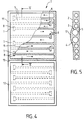
- These means 4 are constituted by a network of transverse cells 5 communicating with each other, such as that which is more particularly illustrated in FIG. 4.
- These cells 5, in the illustrated embodiment communicating with one another via baffles 6 formed by through an orifice 7 formed at at least one of their ends, with a view to authorizing a slow and controlled circulation of said liquid fluid, along a path shown by the arrows referenced 9, which also makes it possible to maintain the liquid fluid in order to keep the accessory 1 the desired shape when at least part of it is in the vertical position.
- each interalveolar communication end 7 has a vertical bulge 8 limiting the circulation speeds of the liquid so as to constitute a hydraulic pressure drop and to ensure a channeling of the circulation of the fluid.
- the orifices 7 ensuring inter-cellular communication are staggered from one end of a cell to the other end of the underlying cell in order to facilitate the flow and the hydraulic circulation of said fluid along a path ensuring an adaptation of article 1, in accordance with the invention, to the morphology of the person.
- each cell 5 is variable, and by way of example the diameter can be between 1 to 4 cm.
- these cells 5 of variable diameter have a predetermined distribution so as to give the structure 3 a profile adapted according to the part of the body intended to be maintained.
- the cells 5 are obtained by hot welding of the base material constituting the envelope 2, which can for example be a heat-sealable plastic material. such as polypropylene or any other material having appropriate characteristics of solidity and flexibility, so as to create the structure 3.
- a heat-sealable plastic material such as polypropylene or any other material having appropriate characteristics of solidity and flexibility
- the envelope 2 may consist of two superimposed sheets of the base material or a sheet folded back on itself.
- the fluid used can be water comprising additives so as to give it a viscosity sufficient to limit its too rapid flow inside the cells 5.
- sucrose or any other adjuvant may be added in liquid form or in the form of a gel to said fluid in order to give it suitable viscosity properties.
- this liquid fluid may also be advantageous to add to this liquid fluid, for example a fungicidal agent to avoid the risks of introduction of molds or pathogens when said fluid is enclosed in the envelope 2, as well as an antifreeze agent. to keep the liquid its suitable fluidity whatever the temperature at which the accessory 1 is used, which increases its usability.
- a fungicidal agent to avoid the risks of introduction of molds or pathogens when said fluid is enclosed in the envelope 2, as well as an antifreeze agent.
- the fluids that may be used as well as the adjuvants associated with them have characteristics that meet the hygiene and / or toxicity standards required for uses intended for people, in particular to avoid the risk of accidents. in case of unexpected contact of these products with the user's skin.
- the seat accessory 1 here consists of two independent parts 11 and 12 connected together by means of a fold line 13 which extends over the entire width of these.
- Each part 11-12 has dimensions adapted to allow its adjustment on a flexible or rigid seat 14, such as for example a car seat or an office seat and as is more particularly illustrated in FIG. 6.
- Part 11 is intended to cover at least partially the backrest 14a of seat 14, while part 12 is intended to cover at least partially seat 14b of said seat 14.
- the part 11 in the position of use has two external flexible lateral beads 15 and 16 extending respectively in the vicinity of each lateral border, intended to mold the lateral parts of the lumbo-gluteal region A of the individual and, on the other share a horizontal progressive bulge 17 of its median part which ensures a molding of the physiological lumbar lordosis B.
- This progressive bulge 17 is, moreover, obtained by means of the progressive increase in this zone of the diameter of the alveoli 5 like this is more particularly illustrated in FIG. 5.
- this part 11 ensures the maintenance of the physiological lordosis of the lumbar spine up to an upper limit which is situated approximately above the dorso-lumbar hinge corresponding to the transition zone of the end of the dorsal kyphosis. physiological towards lumbar lordosis.
- Part 12 has, when the individual is in a seated position, two flexible beads 18, 19 which extend respectively in the vicinity of each of its lateral edges, as is more particularly illustrated in FIG. 3.
- the molding of the part posterior thigh will be obtained by gradually increasing the diameter of the cells 5 in this area, as shown by the arrow 20 in FIG. 6.
- this part 12 maintains the sacred portion of the column comprising the pelvis and the sacrum and the proximal part of the lower limbs C. It should be noted that this part 12 is essential insofar as the position of the pelvis can , alone, change the position of the spine. Indeed, a simple tilting of the pelvis forward and down abnormally accentuates the lumbar lordosis while a simple tilting of the pelvis backwards and upwards generates a reduction of this lordosis.
- parts 11 and 12 as well as their immediate adjustment to the individual and to his movements, thanks to the movements of the liquid filling fluid contained inside these two parts 11 and 12 allow an appropriate molding of the sitting position of the individual, that is to say the lumbosacral column of the pelvis and the proximal part of the lower limbs.
- These heating elements 21 can be constituted for example by a heating resistor 22 associated with a thermostat 23 making it possible to control the desired temperature to which it is desired to bring the fluid.
- the connection of the resistor 22 is also carried out in such a way that it presents total security so as to avoid the risk of electric shock.
- Figures 7 and 8 show an alternative embodiment of the seat accessory of the present invention.
- the seat upholstery 1 is constituted as in the previous embodiment and comprises an external envelope 2 defining an internal structure in which is placed a liquid filling fluid, capable of being put into circulation.
- This structure comprises a network of transverse cells communicating with each other, surrounded by a peripheral bead.
- the bead is continuous and formed by an upper alveolus 21 and a horizontal lower alveolus 22, joined by two lateral vertical alveoli 23-24.
- Said network is itself constituted by in particular eight cells 26-33, transverse communicating with each other, via baffles formed by orifices formed at at least one of their ends, arranged in staggered rows, in order to allow a slow and controlled circulation of the liquid.
- each communication end may have a bulge 33, constituting for said communication orifice a constriction to constitute a hydraulic pressure drop and channel the circulation of the liquid.
- the seat part 37 and the back part 36 communicate through the orifice 34 of the network of cells, the folding axis of the seat upholstery being shown diagrammatically by the dashed line marked 35 on the figure.
- the profile of the cells is variable depending on the part of the body to be maintained, and for example the lateral beads 21-24 are of a width of the order of 20 to 50 mm, similarly for the lower cells 31- 33.
- the other cells form oblong lights and for example the cells 26, 28 have a height between 50 and 100 mm, the cells 27, 29 have a height between 80 and 150 mm, while the cell 30 under the buttocks has a dimension of l '' from 100 to 200 mm.
- the fact that the structure is pre-shaped to the camber of the spine, combined with the means allowing its vertical fixing, allows automatic compensation for movements and deformations of the column and the sacrum.
- the gasket also has a filling valve 38 as well as a drain plug 39.
- a filling valve 38 as well as a drain plug 39.
- two eyelets 40 can advantageously be provided.
Abstract
Description
La présente invention a pour objet un accessoire de siège, destiné notamment à constituer une garniture pour être placée au niveau du dossier et/ou de l'assise d'un siège, qui trouvera son application dans tous les secteurs de l'activité économique dans lesquels il est nécessaire de prévenir des personnes des risques de pathologies lombaires dégénératrices liées notamment au maintien dans une position physiologique inadaptée de la colonne rachidienne lors d'une position assise prolongée de l'individu dans le cadre des activités de la vie courante du travail ou de loisirs.The present invention relates to a seat accessory, intended in particular to constitute a lining to be placed at the level of the backrest and / or the seat of a seat, which will find its application in all sectors of economic activity in which it is necessary to warn people of the risks of degenerative lumbar pathologies linked in particular to the maintenance in an unsuitable physiological position of the spinal column during a prolonged sitting position of the individual within the framework of activities of daily working life or Recreation.
De nombreuses personnes présentent des pathologies lombaires résultant notamment de dégénérescences lombaires liées à une détérioration progressive des structures rachidiennes concernées, telles que les disques intervertébraux, les articulations interapophysaires, et les structures ligamentaires adjacentes. Ces pathologies sont d'autant plus accentuées que la personne reste dans une position assise prolongée dans une posture inadaptée à sa morphologie.Many people have lumbar pathologies resulting in particular from lumbar degenerations linked to a progressive deterioration of the spinal structures concerned, such as the intervertebral discs, the interapophyseal joints, and the adjacent ligament structures. These pathologies are all the more accentuated as the person remains in a prolonged sitting position in a posture unsuitable for his morphology.
Quelles que soient leurs formes et/ou leurs natures, toutes ces pathologies provoquent chez les personnes qui en sont atteintes des douleurs importantes souvent difficilement soulageables.Whatever their forms and / or their natures, all these pathologies cause in people who suffer from them significant pains often difficult to relieve.
Par ailleurs, le coût des techniques mises en oeuvre pour guérir ces douleurs est relativement élevé sans pour autant apporter, en pratique, toujours les résultats escomptés.Furthermore, the cost of the techniques used to cure these pains is relatively high without, in practice, always bringing the expected results.
C'est la raison pour laquelle, on a pensé à développer des structures qui permettent de prévenir de tels problèmes lombaires notamment, lorsque l'individu est destiné à rester dans une position assise prolongée en corrigeant celle-ci, afin de mieux l'adapter à ses caractéristiques physiologiques propres, par exemple en contrôlant sa posture.This is the reason why, we thought of developing structures which make it possible to prevent such lumbar problems in particular, when the individual is intended to remain in a prolonged sitting position by correcting it, in order to better adapt it. to his own physiological characteristics, for example by controlling his posture.
C'est ainsi qu'il est connu d'utiliser des coussins et/ou des structures gonflables que l'on dispose sur les sièges et qui s'adaptent plus ou moins bien à la morphologie externe de l'individu lorsque celui-ci est assis dans ledit siège.It is thus known to use cushions and / or inflatable structures which are placed on the seats and which adapt more or less well to the external morphology of the individual when the latter is sitting in said seat.
Toutefois, en pratique, de telles structures n'apportent pas entière satisfaction puisqu'elles ne permettent pas notamment de se mouler parfaitement à la morphologie de l'individu et d'obtenir un maintien adapté et efficace de la personne.However, in practice, such structures are not entirely satisfactory since they do not in particular make it possible to mold themselves perfectly to the morphology of the individual and to obtain suitable and effective support for the person.
Il est également connu d'utiliser des structures constituées par des chapelets de micro-billes par exemple en bois, et qui sont destinés notamment à être disposés sur les sièges des véhicules automobiles. En pratique, de telles structures n'apportent pas entière satisfaction et, elles ne sont pas, en outre, adaptées en fonction de la morphologie de chaque individu ce qui en limite les capacités d'utilisation.It is also known to use structures constituted by strings of micro-balls, for example made of wood, and which are intended in particular to be placed on the seats of motor vehicles. In practice, such structures are not entirely satisfactory and, moreover, they are not adapted as a function of the morphology of each individual, which limits their capacity for use.
La présente invention a pour but de remédier aux inconvénients des structures actuellement connues en fournissant un accessoire de siège, destiné notamment à constituer une garniture, pour être placée au niveau du dossier et/ou de l'assise du siège qui comporte une structure de l'enveloppe qui présente des moyens permettant d'assurer une conformation de cette structure apte à épouser la morphologie de l'utilisateur.The object of the present invention is to remedy the drawbacks of currently known structures by providing a seat accessory, intended in particular to constitute a lining, to be placed at the level of the backrest and / or of the seat which comprises a structure of the 'envelope which has means for ensuring a conformation of this structure able to match the morphology of the user.
Un avantage de l'accessoire de siège, conforme à l'invention réside dans le fait qu'il peut être utilisé pour équiper tout type de siège quelle que soit sa forme et/ou sa conformation ce qui en accroît ses capacités d'utilisation.An advantage of the seat accessory, in accordance with the invention lies in the fact that it can be used to equip any type of seat whatever its shape and / or its conformation, which increases its usability.
Un autre avantage de l'accessoire de siège conforme à l'invention réside dans le fait qu'il peut être facilement utilisé et ceci quelles que soient les conditions dans lesquelles l'on désire s'en servir.Another advantage of the seat accessory according to the invention lies in the fact that it can be easily used and this whatever the conditions under which it is desired to use it.
Un autre avantage de l'accessoire de siège conforme à l'invention réside dans le fait qu'il peut être fabriqué en série, ce qui en diminue son prix de fabrication.Another advantage of the seat accessory according to the invention lies in the fact that it can be mass produced, which reduces its manufacturing price.
D'autres buts et avantages de la présente invention apparaîtront au cours de la description qui va suivre qui n'est donnée qu'à titre indicatif et qui n'a pas pour but de la limiter.Other objects and advantages of the present invention will appear during the description which follows which is given only for information and which is not intended to limit it.
A cette fin, selon l'invention, l'accessoire de siège, destiné notamment à constituer une garniture pour être placée au niveau du dossier et/ou de l'assise dudit siège, comprenant une enveloppe à l'intérieur de laquelle est placé un fluide liquide de remplissage, est caractérisé par le fait que ladite structure de l'enveloppe comprend des moyens pour permettre une répartition et une canalisation contrôlées dudit fluide liquide en vue d'autoriser une conformation de ladite structure apte à épouser la morphologie de la personne.To this end, according to the invention, the seat accessory, intended in particular to constitute a lining to be placed at the level of the backrest and / or of the seat of said seat, comprising an envelope inside which is placed a liquid filling fluid, is characterized by the fact that said structure of the envelope comprises means for allowing controlled distribution and channeling of said liquid fluid with a view to authorizing a conformation of said structure capable of matching the morphology of the person.
L'invention sera bien comprise à la lecture de la description suivante accompagnée des dessins en annexe parmi lesquels :
- la figure 1 est une vue schématique qui illustre en perspective un article déformable conforme à l'invention équipé d'une résistance pour éviter l'hypothermie,
- la figure 2 est une vue schématique en coupe selon la ligne II-II de la figure 1 illustrant le maintien de la partie de la lordose physiologique de la colonne lombaire,
- la figure 3 est une vue schématique en coupe selon la ligne III-III de la figure 1 qui illustre le maintien de la partie proximale des membres inférieurs,
- la figure 4 est une vue schématique qui illustre en coupe partielle la structure de l'article conforme à l'invention,
- la figure 5 est une vue schématique en coupe selon la ligne V-V de la figure 4 qui illustre le réseau d'alvéoles communiquant entre eux à-travers des chicanes formées par l'intermédiaire d'un orifice ménagé à au moins une de leurs extrémités,
- la figure 6 est une vue en coupe partielle illustrant la garniture de siège de la présente invention des figures 4 et 5, disposée sur un dossier et une assise de siège permettant de visualiser le maintien adapté de l'individu,
- la figure 7 est une vue schématique qui montre un accessoire de siège en plan réalisé selon une autre variante,
- la figure 8 est une vue en coupe selon l'axe VIII-VIII qui illustre la forme du réseau d'alvéoles de la garniture de la figure 7.
- FIG. 1 is a schematic view which illustrates in perspective a deformable article in accordance with the invention equipped with a resistor to avoid hypothermia,
- FIG. 2 is a diagrammatic sectional view along line II-II of FIG. 1 illustrating the maintenance of the part of the physiological lordosis of the lumbar spine,
- FIG. 3 is a diagrammatic sectional view along line III-III of FIG. 1 which illustrates the maintenance of the proximal part of the lower limbs,
- FIG. 4 is a schematic view which illustrates in partial section the structure of the article according to the invention,
- FIG. 5 is a schematic sectional view along the line VV of FIG. 4 which illustrates the network of cells communicating with each other through baffles formed by means of an orifice formed at at least one of their ends,
- FIG. 6 is a partial sectional view illustrating the seat upholstery of the present invention of FIGS. 4 and 5, arranged on a backrest and a seat cushion making it possible to view the adapted support of the individual,
- FIG. 7 is a schematic view which shows a planar seat accessory produced according to a other variant,
- FIG. 8 is a sectional view along the axis VIII-VIII which illustrates the shape of the network of cells of the lining of FIG. 7.
La présente invention est relative à un accessoire de siège, destiné notamment à constituer une garniture pour être placée au niveau du dossier et/ou de l'assise du siège, qui trouvera son application dans tous les secteurs de l'activité économique dans lesquels il est nécessaire de prévenir des personnes des risques de pathologies lombaires dégénératrices liées notamment au maintien dans une position physiologique inadaptée de la colonne rachidienne lors d'une position assise prolongée de l'individu dans le cadre des activités de la vie courante du travail ou de loisirs.The present invention relates to a seat accessory, intended in particular to constitute a trim to be placed at the level of the backrest and / or the seat, which will find its application in all sectors of economic activity in which it it is necessary to warn people of the risks of degenerative lumbar pathologies linked in particular to the maintenance in an unsuitable physiological position of the spinal column during a prolonged sitting position of the individual within the framework of activities of daily life at work or leisure .
En outre, le but principal de la présente invention est d'obtenir un accessoire de siège qui permet de mouler les structures lombo-fessières en conservant leurs rapports anatomo-physiologiques propres à chaque individu.In addition, the main object of the present invention is to obtain a seat accessory which makes it possible to mold the lumbo-gluteal structures while preserving their anatomo-physiological relationships specific to each individual.
En effet, dans la majorité des cas, l'anatomie lombo-fessière s'ajuste à la forme du siège, alors que, théoriquement, le siège devrait s'adapter à l'individu pour ne pas modifier, de façon durable, les rapports anatomiques lombo-fessiers propres à chaque personne. Cette modification a pour conséquence une contrainte physique excessive des structures de la colonne lombo-sacrée pouvant déboucher sur une gêne douloureuse intermittente puis permanente à plus ou moins long terme, et ce d'autant plus, que le sujet est soumis à de telles pathologies notamment dégénératives, constituées par une évolution du cartilage résultant d'une usure progressive spontanée de celui-ci et que cette évolution est favorisée, en outre, par certains facteurs étiologiques.In fact, in most cases, the lumbar-gluteal anatomy adjusts to the shape of the seat, whereas, theoretically, the seat should adapt to the individual so as not to modify, in a lasting manner, the relationships anatomical lumbo-glutes specific to each person. The consequence of this modification is excessive physical stress on the structures of the lumbosacral spine, which can lead to intermittent painful discomfort then permanent in the more or less long term, and all the more so since the subject is subjected to such pathologies in particular. degenerative, formed by an evolution of the cartilage resulting from a spontaneous progressive wear of this one and that this evolution is favored, moreover, by certain etiological factors.
Pour cela, l'accessoire de siège 1 conforme à l'invention comprend une enveloppe externe 2 définissant une structure 3 à l'intérieur de laquelle est placé un fluide liquide de remplissage apte à être mis en circulation.For this, the
Ladite structure 3 comprend des moyens 4 pour permettre une répartition et une canalisation lente et contrôlée dudit fluide liquide en vue d'assurer une conformation de cette structure 3 apte à épouser la morphologie de l'utilisateur.Said
Ces moyens 4 sont constitués par un réseau d'alvéoles 5, transversaux communiquant entre eux, tel que celui qui est plus particulièrement illustré à la figure 4. Ces alvéoles 5, dans la forme de réalisation illustrée communiquant entre eux via des chicanes 6 formées par l'intermédiaire d'un orifice 7 ménagé à au moins l'une de leurs extrémités, en vue d'autoriser une circulation lente et contrôlée dudit fluide liquide, selon un parcours montré par les flèches référencées 9, qui permet en outre de maintenir le fluide liquide afin de conserver à l'accessoire 1 la forme voulue lorsqu'au moins une partie de celui-ci est en position verticale.These means 4 are constituted by a network of
En outre, chaque extrémité de communication interalvéolaire 7 présente un renflement vertical 8 limitant les vitesses de circulation du liquide de manière à constituer une perte de charge hydraulique et à assurer une canalisation de la circulation du fluide.In addition, each interalveolar communication end 7 has a
Les orifices 7 assurant la communication interalvéolaire, sont disposés en quinconce depuis l'une des extrémités d'un alvéole à l'autre extrémité de l'alvéole sous-jacent afin de faciliter l'écoulement et la circulation hydraulique dudit fluide selon un trajet assurant une adaptation de l'article 1, conforme à l'invention, à la morphologie de la personne.The orifices 7 ensuring inter-cellular communication, are staggered from one end of a cell to the other end of the underlying cell in order to facilitate the flow and the hydraulic circulation of said fluid along a path ensuring an adaptation of
Il est également à noter que la dimension de chaque alvéole 5 est variable, et à titre d'exemple le diamètre peut être compris entre 1 à 4 cm. En outre, ces alvéoles 5 de diamètre variable présentent une répartition prédéterminée de manière à conférer à la structure 3 un profil adapté en fonction de la partie du corps destinée à être maintenue.It should also be noted that the dimension of each
Les alvéoles 5 sont obtenues par une soudure à chaud du matériau de base constituant l'enveloppe 2, qui peut être par exemple une matière plastique thermo-soudable telle que du polypropylène ou tout autre matériau présentant des caractéristiques de solidité et de souplesse appropriées, de façon à créer la structure 3.The
L'enveloppe 2 peut être constituée par deux feuilles superposées du matériau de base ou une feuille repliée sur elle-même.The
Le fluide utilisé peut être de l'eau comportant des adjuvants de manière à lui conférer une viscosité suffisante pour limiter son écoulement trop rapide à l'intérieur des alvéoles 5.The fluid used can be water comprising additives so as to give it a viscosity sufficient to limit its too rapid flow inside the
A titre d'exemple, l'on peut ajouter une quantité déterminée de sucrose ou de tout autre adjuvant sous forme liquide ou sous forme de gel audit fluide afin de lui conférer des propriétés de viscosité adaptées.By way of example, a determined quantity of sucrose or any other adjuvant may be added in liquid form or in the form of a gel to said fluid in order to give it suitable viscosity properties.
Il peut être également avantageux, d'adjoindre à ce fluide liquide, par exemple un agent fongicide pour éviter les risques d'introduction de moisissures ou d'agents pathogènes lorsque ledit fluide est enfermé dans l'enveloppe 2, ainsi qu'un agent antigel pour conserver au liquide sa fluidité adaptée quelle que soit la température à laquelle est utilisée l'accessoire 1, ce qui en accroît ses capacités d'utilisation.It may also be advantageous to add to this liquid fluid, for example a fungicidal agent to avoid the risks of introduction of molds or pathogens when said fluid is enclosed in the
En outre, les fluides susceptibles d'être utilisés ainsi que les adjuvants qui lui sont associés présentent des caractéristiques répondant aux normes d'hygiène et/ou de toxicité requises pour des utilisations destinées à des personnes afin notamment d'éviter des risques d'accidents en cas d'un contact inopiné de ces produits avec la peau de l'utilisateur.In addition, the fluids that may be used as well as the adjuvants associated with them have characteristics that meet the hygiene and / or toxicity standards required for uses intended for people, in particular to avoid the risk of accidents. in case of unexpected contact of these products with the user's skin.
Il faut également noter que, pour accroître le confort et la souplesse de l'accessoire 1, on remplit celui-ci partiellement par une quantité de liquide adaptée en fonction des besoins et du poids de l'utilisateur. Ainsi, la circulation du fluide est rendue possible à l'intérieur de la structure pour une bonne efficacité de l'accessoire. En aucun cas, il ne peut être envisagé de remplir la structure complètement car, alors, la circulation ne serait plus possible et il n'y aurait plus d'adaptation d'accessoire à la morphologie de l'utilisateur.It should also be noted that, to increase the comfort and flexibility of the
Dans la forme de réalisation illustrée aux figures 1 et 4, l'accessoire de siège 1 est ici constitué de deux parties 11 et 12 indépendantes reliées entre elles par l'intermédiaire d'une ligne de pliage 13 qui s'étend sur toute la largeur de celles-ci. Chaque partie 11-12, présente des dimensions adaptées pour permettre son ajustement sur un siège souple 14 ou rigide, tel que par exemple un siège automobile ou un siège bureau et comme cela est plus particulièrement illustré à la figure 6.In the embodiment illustrated in Figures 1 and 4, the
La partie 11 est destinée à recouvrir au moins partiellement le dossier 14a du siège 14, tandis que la partie 12 est destinée à recouvrir au moins partiellement l'assise 14b dudit siège 14.
La partie 11 en position d'utilisation présente deux bourrelets latéraux souples externes 15 et 16 s'étendant respectivement au voisinage de chaque bordure latérale, destinés à mouler les parties latérales de la région lombo-fessière A de l'individu et, d'autre part un renflement 17 progressif horizontal de sa partie médiane qui assure un moulage de la lordose lombaire physiologique B. Ce renflement progressif 17 est, en outre, obtenu par l'intermédiaire de l'accroissement progressif dans cette zone du diamètre des alvéoles 5 comme cela est plus particulièrement illustré à la figure 5.The
De cette façon, cette partie 11 assure le maintien de la lordose physiologique de la colonne lombaire jusqu'à une limite supérieure qui se situe approximativement au-dessus de la charnière dorso-lombaire correspondant à la zone de transition de la fin de la cyphose dorsale physiologique vers la lordose lombaire.In this way, this
La partie 12 présente, lorsque l'individu est en position assise, deux bourrelets 18, 19 souples qui s'étendent respectivement au voisinage de chacune de ses bordures latérales, comme cela est plus particulièrement illustré à la figure 3. Le moulage de la partie postérieure de la cuisse sera, quant à lui, obtenu par l'accroissement progressif du diamètre des alvéoles 5 dans cette zone, tel que montré par la flèche 20 à la figure 6.
Ainsi, cette partie 12 assure le maintien de la portion sacrée de la colonne comprenant le bassin et le sacrum et de la partie proximale des membres inférieurs C. Il est à remarquer que cette partie 12 est essentielle dans la mesure où la position du bassin peut, à elle seule, modifier la position de la colonne vertébrale. En effet, un simple basculement du bassin vers l'avant et le bas accentue anormalement la lordose lombaire tandis qu'un simple basculement du bassin vers l'arrière et le haut génère une réduction de cette lordose.Thus, this
Les caractéristiques des parties 11 et 12 ainsi que leur ajustement immédiat à l'individu et à ses mouvements, grâce aux mouvements du fluide liquide de remplissage contenu à l'intérieur de ces deux parties 11 et 12 permettent un moulage approprié de la position assise de l'individu c'est-à-dire de la colonne lombo-sacrée du bassin et de la partie proximale des membres inférieurs. Outre le confort assuré, on obtient, ainsi un maintien des rapports anatomiques adaptés à la physiologie musculo-squelettique de chaque individu et de ce fait, on diminue considérablement les risques pathologiques.The characteristics of
Afin d'accroître les capacités d'utilisation de l'accessoire 1 conforme à l'invention, il est également prévu de l'équiper d'éléments chauffants 21 qui permettent de maintenir à une température désirée le fluide disposé à l'intérieur de l'article et ainsi d'éviter par exemple les risques d'hypothermie.In order to increase the capacities of use of the
Ces éléments chauffants 21 peuvent être constitués par exemple par une résistance chauffante 22 associée à un thermostat 23 permettant de contrôler la température désirée à laquelle l'on désire porter le fluide. Le branchement de la résistance 22 est réalisé en outre de manière à ce qu'il présente une sécurité totale de manière à éviter les risques d'électrocution.These
L'invention ne se limite pas à la forme de réalisation qui a été décrite ci-dessus mais elle en embrasse au contraire toutes les variantes de réalisation.The invention is not limited to the embodiment which has been described above but on the contrary embraces all the variant embodiments thereof.
A ce sujet, les figures 7 et 8 montrent une variante de réalisation de l'accessoire de siège de la présente invention.In this regard, Figures 7 and 8 show an alternative embodiment of the seat accessory of the present invention.
Dans cette variante de réalisation, la garniture de siège 1 est constituée comme dans le mode de réalisation précédent et comprend une enveloppe externe 2 définissant une structure interne dans laquelle est placé un fluide liquide de remplissage, apte à être mis en circulation.In this alternative embodiment, the
Cette structure comprend un réseau d'alvéoles transversaux communiquant entre eux, entourés par un bourrelet périphérique.This structure comprises a network of transverse cells communicating with each other, surrounded by a peripheral bead.
Plus précisément, le bourrelet est continu et formé par un alvéole supérieur 21 et un alvéole inférieur 22 horizontaux, réuni par deux alvéoles verticaux latéraux 23-24.More specifically, the bead is continuous and formed by an
Ces bourrelets 21-24 communiquent avec le réseau d'alvéoles horizontaux internes en 41-42. Les alvéoles périphériques assurent en eux-mêmes une première régulation fondamentale de l'écoulement du liquide.These beads 21-24 communicate with the network of internal horizontal cells at 41-42. The peripheral cells provide in themselves a first fundamental regulation of the flow of the liquid.
Ledit réseau est quant à lui constitué par notamment huit alvéoles 26-33, transversaux communiquant entre eux, via des chicanes formées par l'intermédiaire d'orifices ménagés à au moins l'une de leurs extrémités, disposés en quinconce, en vue d'autoriser une circulation lente et contrôlée du liquide.Said network is itself constituted by in particular eight cells 26-33, transverse communicating with each other, via baffles formed by orifices formed at at least one of their ends, arranged in staggered rows, in order to allow a slow and controlled circulation of the liquid.
Comme dans le mode de réalisation précédent, chaque extrémité de communication peut présenter un renflement 33, constituant pour ledit orifice de communication un étranglement pour constituer une perte de charge hydraulique et canaliser la circulation du liquide.As in the previous embodiment, each communication end may have a
Cela étant, dans ce second mode de réalisation, la partie assise 37 et la partie dossier 36 communiquent par l'orifice 34 du réseau d'alvéoles, l'axe de pliage de la garniture de siège étant schématisé par le trait mixte repéré 35 sur la figure.However, in this second embodiment, the
Dans cet exemple, le profil des alvéoles est variable selon la partie du corps à maintenir, et par exemple les bourrelets latéraux 21-24 sont d'une largeur de l'ordre de 20 à 50 mm, de même pour les alvéoles inférieurs 31-33. Les autres alvéoles forment des lumières oblongues et par exemple les alvéoles 26, 28 présentent une hauteur comprise entre 50 et 100 mm, les alvéoles 27, 29 présentent une hauteur comprise entre 80 et 150 mm, tandis que l'alvéole 30 sous les fesses présente quant à lui une dimension de l'ordre de 100 à 200 mm.In this example, the profile of the cells is variable depending on the part of the body to be maintained, and for example the lateral beads 21-24 are of a width of the order of 20 to 50 mm, similarly for the lower cells 31- 33. The other cells form oblong lights and for example the
Selon la présente invention, le fait que la structure soit pré-conformée à la cambrure de la colonne vertébrale, combiné aux moyens permettant sa fixation verticale, permet une compensation automatique des mouvements et des déformations de la colonne et du sacrum.According to the present invention, the fact that the structure is pre-shaped to the camber of the spine, combined with the means allowing its vertical fixing, allows automatic compensation for movements and deformations of the column and the sacrum.
La garniture présente également une valve de remplissage 38 ainsi qu'un bouchon de vidange 39. En outre, pour maintenir le haut du dossier de la garniture, on pourra avantageusement prévoir deux oeillets 40.The gasket also has a filling
Claims (10)
Applications Claiming Priority (2)
| Application Number | Priority Date | Filing Date | Title |
|---|---|---|---|
| FR9304720 | 1993-04-16 | ||
| FR9304720A FR2703891B1 (en) | 1993-04-16 | 1993-04-16 | SEAT ACCESSORY, IN PARTICULAR FOR CONSTITUTING A TRIM TO BE PLACED AT THE LEVEL OF THE BACKREST AND / OR THE SEAT OF A SEAT. |
Publications (2)
| Publication Number | Publication Date |
|---|---|
| EP0619968A1 true EP0619968A1 (en) | 1994-10-19 |
| EP0619968B1 EP0619968B1 (en) | 1998-07-08 |
Family
ID=9446300
Family Applications (1)
| Application Number | Title | Priority Date | Filing Date |
|---|---|---|---|
| EP94490016A Expired - Lifetime EP0619968B1 (en) | 1993-04-16 | 1994-04-15 | Accessory for a seat to be placed on the seat and/or back of a seat |
Country Status (3)
| Country | Link |
|---|---|
| EP (1) | EP0619968B1 (en) |
| DE (2) | DE619968T1 (en) |
| FR (1) | FR2703891B1 (en) |
Cited By (2)
| Publication number | Priority date | Publication date | Assignee | Title |
|---|---|---|---|---|
| US7172247B2 (en) | 2002-08-07 | 2007-02-06 | Brose Fahrzeugteile Gmbh & Co Kg, Coburg | Motor vehicle seat system, control arrangement, actuating arrangement, and process for control of a lumbar adjustment device of a motor vehicle seat |
| US8157325B2 (en) | 2003-12-30 | 2012-04-17 | Hni Technologies Inc. | Chair back rest with improved resilience and support |
Families Citing this family (2)
| Publication number | Priority date | Publication date | Assignee | Title |
|---|---|---|---|---|
| DE10061430B4 (en) * | 2000-12-09 | 2007-04-12 | Bernhard Schneider | Fluid-flowed interior trim of a vehicle body |
| DE10261899B4 (en) * | 2002-12-23 | 2015-11-26 | Volkswagen Ag | Method and system for massage of body parts with a lordosis |
Citations (6)
| Publication number | Priority date | Publication date | Assignee | Title |
|---|---|---|---|---|
| FR1306814A (en) * | 1960-11-14 | 1962-10-19 | Pneumatic vehicle seat | |
| US3112956A (en) * | 1961-08-30 | 1963-12-03 | Schick Melvin Edward | Inflatable seat and back rest |
| DE1405778A1 (en) * | 1961-11-02 | 1968-11-28 | Automation Hans Nix Elek Sche | Resilient support cushion |
| US4561441A (en) * | 1984-08-09 | 1985-12-31 | Kolodziej Ronald M | Liquid back support pad for inclined surfaces |
| EP0170947A1 (en) * | 1984-07-24 | 1986-02-12 | Lasse Hessel | Resilient supporting device |
| FR2599249A1 (en) * | 1986-05-28 | 1987-12-04 | Inst Nat Sante Rech Med | Pneumatic element for making cushions, mattresses and seats, generally for the sick |
-
1993
- 1993-04-16 FR FR9304720A patent/FR2703891B1/en not_active Expired - Fee Related
-
1994
- 1994-04-15 DE DE0619968T patent/DE619968T1/en active Pending
- 1994-04-15 EP EP94490016A patent/EP0619968B1/en not_active Expired - Lifetime
- 1994-04-15 DE DE69411432T patent/DE69411432T2/en not_active Expired - Fee Related
Patent Citations (6)
| Publication number | Priority date | Publication date | Assignee | Title |
|---|---|---|---|---|
| FR1306814A (en) * | 1960-11-14 | 1962-10-19 | Pneumatic vehicle seat | |
| US3112956A (en) * | 1961-08-30 | 1963-12-03 | Schick Melvin Edward | Inflatable seat and back rest |
| DE1405778A1 (en) * | 1961-11-02 | 1968-11-28 | Automation Hans Nix Elek Sche | Resilient support cushion |
| EP0170947A1 (en) * | 1984-07-24 | 1986-02-12 | Lasse Hessel | Resilient supporting device |
| US4561441A (en) * | 1984-08-09 | 1985-12-31 | Kolodziej Ronald M | Liquid back support pad for inclined surfaces |
| FR2599249A1 (en) * | 1986-05-28 | 1987-12-04 | Inst Nat Sante Rech Med | Pneumatic element for making cushions, mattresses and seats, generally for the sick |
Cited By (2)
| Publication number | Priority date | Publication date | Assignee | Title |
|---|---|---|---|---|
| US7172247B2 (en) | 2002-08-07 | 2007-02-06 | Brose Fahrzeugteile Gmbh & Co Kg, Coburg | Motor vehicle seat system, control arrangement, actuating arrangement, and process for control of a lumbar adjustment device of a motor vehicle seat |
| US8157325B2 (en) | 2003-12-30 | 2012-04-17 | Hni Technologies Inc. | Chair back rest with improved resilience and support |
Also Published As
| Publication number | Publication date |
|---|---|
| FR2703891A1 (en) | 1994-10-21 |
| FR2703891B1 (en) | 1995-06-23 |
| DE69411432D1 (en) | 1998-08-13 |
| DE69411432T2 (en) | 1999-03-25 |
| EP0619968B1 (en) | 1998-07-08 |
| DE619968T1 (en) | 1996-10-10 |
Similar Documents
| Publication | Publication Date | Title |
|---|---|---|
| FR2815837A1 (en) | Cervical pillow for protecting cervical vertebrae, has pair of auxiliary supporting sections with ear accommodating opening on both sides of neck supporting section | |
| EP0230389B1 (en) | Mattress of individual modular elements and use in the making of arm-chairs, cushions and detachable backrests | |
| EP2173207B1 (en) | Wear sole for footwear and method and mould for making such sole | |
| EP0495902B1 (en) | Rigid wraparound shell defining a sealed inner space | |
| EP2227117A2 (en) | Asymmetrical body cushion that can be used in a 3/4 ventral position | |
| FR2483203A1 (en) | ARTICULATED BED STRUCTURE AND FLOTATION MATTRESS FOR THIS BED | |
| FR2537432A1 (en) | DEVICE FOR STABILIZING THE BASIN OF A LAYERED PATIENT | |
| FR2672195A1 (en) | Improved dynamic support | |
| EP0619968B1 (en) | Accessory for a seat to be placed on the seat and/or back of a seat | |
| FR2748639A3 (en) | ADDITIONAL SEAT-BACK FOR VEHICLES | |
| EP1494627A1 (en) | Splint for a joint connection and methods for production of such a splint | |
| EP0670688B1 (en) | Medical mattress | |
| EP2449926B1 (en) | Mattress for a baby | |
| CA2912981C (en) | Modular device for dorsal protection | |
| EP0880925A1 (en) | Multiposition anatomic pillow | |
| FR2648999A1 (en) | Inflatable travel pillow | |
| FR2638965A1 (en) | Support cushion | |
| KR101787439B1 (en) | Functional pillow | |
| FR2573972A1 (en) | Shaped pillow, which can be adapted to the morphology of the user and is of elastic consistency | |
| EP0382663B1 (en) | System for the mobility, stability and reaction of a human body in a seated position | |
| FR2506151A1 (en) | Therapeutic pillow for neck - comprises hollow plastics vessel filled with hot liq. and with curved supple upper surface | |
| FR3117322A1 (en) | Item of furniture, in particular furniture, of the armchair, bench, bed, box spring or similar type | |
| EP0774222B1 (en) | Chair adjustable to the shape of the user | |
| FR2700675A1 (en) | School satchel including at least one inflatable back element | |
| ES2355791T3 (en) | FOLDING BACKUP. |
Legal Events
| Date | Code | Title | Description |
|---|---|---|---|
| PUAI | Public reference made under article 153(3) epc to a published international application that has entered the european phase |
Free format text: ORIGINAL CODE: 0009012 |
|
| AK | Designated contracting states |
Kind code of ref document: A1 Designated state(s): BE DE FR GB IT LU NL |
|
| ITCL | It: translation for ep claims filed |
Representative=s name: UFFICIO BREVETTI RICCARDI & CO |
|
| 17P | Request for examination filed |
Effective date: 19950318 |
|
| GBC | Gb: translation of claims filed (gb section 78(7)/1977) | ||
| TCNL | Nl: translation of patent claims filed | ||
| 17Q | First examination report despatched |
Effective date: 19960307 |
|
| DET | De: translation of patent claims | ||
| GRAG | Despatch of communication of intention to grant |
Free format text: ORIGINAL CODE: EPIDOS AGRA |
|
| GRAG | Despatch of communication of intention to grant |
Free format text: ORIGINAL CODE: EPIDOS AGRA |
|
| GRAH | Despatch of communication of intention to grant a patent |
Free format text: ORIGINAL CODE: EPIDOS IGRA |
|
| GRAH | Despatch of communication of intention to grant a patent |
Free format text: ORIGINAL CODE: EPIDOS IGRA |
|
| GRAA | (expected) grant |
Free format text: ORIGINAL CODE: 0009210 |
|
| AK | Designated contracting states |
Kind code of ref document: B1 Designated state(s): BE DE FR GB IT LU NL |
|
| PG25 | Lapsed in a contracting state [announced via postgrant information from national office to epo] |
Ref country code: NL Free format text: LAPSE BECAUSE OF FAILURE TO SUBMIT A TRANSLATION OF THE DESCRIPTION OR TO PAY THE FEE WITHIN THE PRESCRIBED TIME-LIMIT Effective date: 19980708 |
|
| REF | Corresponds to: |
Ref document number: 69411432 Country of ref document: DE Date of ref document: 19980813 |
|
| GBT | Gb: translation of ep patent filed (gb section 77(6)(a)/1977) |
Effective date: 19981006 |
|
| NLV1 | Nl: lapsed or annulled due to failure to fulfill the requirements of art. 29p and 29m of the patents act | ||
| PLBE | No opposition filed within time limit |
Free format text: ORIGINAL CODE: 0009261 |
|
| STAA | Information on the status of an ep patent application or granted ep patent |
Free format text: STATUS: NO OPPOSITION FILED WITHIN TIME LIMIT |
|
| 26N | No opposition filed | ||
| PG25 | Lapsed in a contracting state [announced via postgrant information from national office to epo] |
Ref country code: FR Free format text: LAPSE BECAUSE OF NON-PAYMENT OF DUE FEES Effective date: 19991231 |
|
| REG | Reference to a national code |
Ref country code: FR Ref legal event code: ST |
|
| PGFP | Annual fee paid to national office [announced via postgrant information from national office to epo] |
Ref country code: DE Payment date: 20000410 Year of fee payment: 7 |
|
| PGFP | Annual fee paid to national office [announced via postgrant information from national office to epo] |
Ref country code: LU Payment date: 20000411 Year of fee payment: 7 |
|
| PGFP | Annual fee paid to national office [announced via postgrant information from national office to epo] |
Ref country code: GB Payment date: 20000412 Year of fee payment: 7 |
|
| PGFP | Annual fee paid to national office [announced via postgrant information from national office to epo] |
Ref country code: BE Payment date: 20000622 Year of fee payment: 7 |
|
| PG25 | Lapsed in a contracting state [announced via postgrant information from national office to epo] |
Ref country code: LU Free format text: LAPSE BECAUSE OF NON-PAYMENT OF DUE FEES Effective date: 20010415 Ref country code: GB Free format text: LAPSE BECAUSE OF NON-PAYMENT OF DUE FEES Effective date: 20010415 |
|
| PG25 | Lapsed in a contracting state [announced via postgrant information from national office to epo] |
Ref country code: BE Free format text: LAPSE BECAUSE OF NON-PAYMENT OF DUE FEES Effective date: 20010430 |
|
| BERE | Be: lapsed |
Owner name: DECANT XAVIER Effective date: 20010430 Owner name: POUBELLE PATRICE Effective date: 20010430 Owner name: LAVEISSIERE CLAUDE Effective date: 20010430 Owner name: S.A. ACHILLE BAYART & CIE Effective date: 20010430 |
|
| GBPC | Gb: european patent ceased through non-payment of renewal fee |
Effective date: 20010415 |
|
| PG25 | Lapsed in a contracting state [announced via postgrant information from national office to epo] |
Ref country code: DE Free format text: LAPSE BECAUSE OF NON-PAYMENT OF DUE FEES Effective date: 20020201 |
|
| PG25 | Lapsed in a contracting state [announced via postgrant information from national office to epo] |
Ref country code: IT Free format text: LAPSE BECAUSE OF NON-PAYMENT OF DUE FEES;WARNING: LAPSES OF ITALIAN PATENTS WITH EFFECTIVE DATE BEFORE 2007 MAY HAVE OCCURRED AT ANY TIME BEFORE 2007. THE CORRECT EFFECTIVE DATE MAY BE DIFFERENT FROM THE ONE RECORDED. Effective date: 20050415 |