EP0619189A2 - Transfer ribbon cassette, a case for enclosing the cassette and a paint film transfer device having the same - Google Patents
Transfer ribbon cassette, a case for enclosing the cassette and a paint film transfer device having the same Download PDFInfo
- Publication number
- EP0619189A2 EP0619189A2 EP94105272A EP94105272A EP0619189A2 EP 0619189 A2 EP0619189 A2 EP 0619189A2 EP 94105272 A EP94105272 A EP 94105272A EP 94105272 A EP94105272 A EP 94105272A EP 0619189 A2 EP0619189 A2 EP 0619189A2
- Authority
- EP
- European Patent Office
- Prior art keywords
- transfer
- core
- transfer ribbon
- case
- takeup
- Prior art date
- Legal status (The legal status is an assumption and is not a legal conclusion. Google has not performed a legal analysis and makes no representation as to the accuracy of the status listed.)
- Granted
Links
Images


Classifications
-
- B—PERFORMING OPERATIONS; TRANSPORTING
- B65—CONVEYING; PACKING; STORING; HANDLING THIN OR FILAMENTARY MATERIAL
- B65H—HANDLING THIN OR FILAMENTARY MATERIAL, e.g. SHEETS, WEBS, CABLES
- B65H37/00—Article or web delivery apparatus incorporating devices for performing specified auxiliary operations
- B65H37/002—Web delivery apparatus, the web serving as support for articles, material or another web
- B65H37/005—Hand-held apparatus
- B65H37/007—Applicators for applying coatings, e.g. correction, colour or adhesive coatings
Definitions
- This invention relates transfer ribbon cassettes. More particularly, the invention relates to a transfer ribbon cassette having a transfer ribbon wound around a feed core and a takeup core maintained in predetermined relative positions by a holder for mounting in a case, the transfer ribbon having a transfer paint film applied to one surface thereof, such as a paint film for use in correcting characters, an adhesive film for bonding purposes or a colored paint film for ornamental use.
- the invention relates also to a case for enclosing this cassette, and to a paint film transfer device having the cassette.
- a conventional transfer ribbon cassette as shown in Fig. 28, has a pair of right and left plates 01 connected to each other through spacers 05, with a space therebetween corresponding to a ribbon width.
- a transfer ribbon R is wound around a feed core 02 and a takeup core 03 supported by a holder 04 in the form of a box-like frame.
- the two cores 02 and 03 are supported at opposite axial ends thereof by the pair of plates 01, and fixed to a relative positional relationship to be placed in a transfer device case.
- the holder 04 not only requires numerous materials for manufacture, but has a complicated construction. Its fabrication and assembly of the feed core 02 and takeup core 03 are of low productivity, consuming a great deal of time and trouble. Such a transfer ribbon cassette has the disadvantage of high manufacturing cost.
- a primary object of the present invention is to provide a transfer ribbon cassette which may be manufactured at lower cost than the conventional transfer ribbon cassette, with an improved support structure for the feed core and takeup core, as well as a case for enclosing this transfer ribbon cassette.
- a further object of the present invention is to provide a paint film transfer device having the above transfer ribbon cassette and easy to use.
- each of the feed core and takeup core is rotatably supported at one end thereof and, when mounted in the case, has a free axial end thereof supported by the case.
- each core is supported at one end thereof by the holder and at the other end by the case when mounted in the case.
- the holder for supporting the feed core and takeup core need not be formed in a box-like frame capable of supporting opposite axial ends of each core.
- the holder has a simplified construction with less materials required for its manufacture. Its fabrication and assembly of the feed core and takeup core are carried out with greater ease and higher productivity and at less cost than in the prior art.
- Each core may have a first restrictor defined at the free axial end thereof for checking displacement of the transfer ribbon toward the free axial end.
- the first restrictor prevents the transfer ribbon from slipping off the core. Even if the transfer ribbon wound around this core should contact the first restrictor, there would be no possibility of an increased resistance being applied to running of the transfer ribbon since the first restrictor is rotatable with the transfer ribbon wound on the core.
- This construction facilitates reliable attachment to the case, requiring only a light operating force.
- the transfer ribbon cassette may further comprise a transfer head for pressing the transfer ribbon upon a receiving surface to transfer the transfer film to the receiving surface, and second restrictors for checking transverse displacement of the transfer ribbon moving past the transfer head, the second restrictors being formed of resin integrally with the holder to support opposite ends of the transfer head transversely of the transfer ribbon.
- This provides a simplified support structure for the transfer head, and allows the transfer ribbon to be wound around the transfer head in advance.
- the transfer ribbon cassette may be manufactured at still less cost.
- the transfer ribbon cassette may be assembled to the case quickly and reliably without requiring skill since the transfer ribbon need not be passed around the transfer head in time of assembly.
- the holder may rotatably support one end of each of the feed core and takeup core, such that a portion of the transfer ribbon extending from the feed core to the takeup core is visible through the holder.
- a transfer ribbon cassette as noted in the outset hereof is provided, wherein each core is rotatably supported at one end thereof and, when mounted in the case, has a free axial end thereof supported by the case, the holder being removable from the feed core and takeup core.
- the holder for supporting the feed core and takeup core need not be formed in a box-like frame capable of supporting opposite axial ends of each core.
- the holder may be removed from the cores when the cores are attached to the case, and hence the holder need not be contained along with the cores in the case.
- the holder has a simplified construction with less materials required for its manufacture. Its fabrication and assembly of the feed core and takeup core are carried out with greater ease and higher productivity and at less cost than in the prior art. In addition, the case may be formed small.
- the holder since the holder is removable from the cores attached to the case, the holder may include a rotation stopper mechanism for the cores, to avoid relaxation of the transfer ribbon without being attached to the case.
- a case for enclosing a transfer ribbon cassette comprises an elastic member elastically deformable upon closure of the case, and engaging members for maintaining the case in a closed position. When the engaging members are disengaged, the elastic member returns to an original shape.
- This construction has the advantage of facilitating opening of the case, compared with manual opening of the case while disengaging the engaging members.
- a paint film transfer device comprises a slip interlock mechanism including a large diameter pulley rotatable with the feed core, a small diameter pulley rotatable with the takeup core, and a transmission belt wound around the large diameter pulley and the small diameter pulley.
- the slip interlock mechanism has no play such as backlash therein. Even when the slip interlock mechanism is moved in either direction while the transfer ribbon cassette is detached from the case, the takeup core rotates with the feed core at an initial stage of rotation of the feed core in a first transfer operation after the transfer ribbon cassette is loaded into the case. Consequently, a used portion of the transfer ribbon in light contact with the transfer ribbon on the feed core has no possibility of moving past a predetermined peeling position to be drawn onto the feed core. The used portion of the transfer ribbon is not relaxed before the takeup core starts taking up the used portion. Thus, the used portion of the transfer ribbon is taken up on the takeup core under suitable tension.
- This construction provides the advantage of reducing the torque of the takeup core necessary for taking up the used portion of the transfer ribbon.
- the used portion of the transfer ribbon to be taken up on the takeup core imparts little resistance to feeding of the transfer ribbon from the feed core during a first transfer operation after the transfer ribbon cassette is loaded into the case. Consequently, the transfer ribbon may run in a normal way, and a used portion of the transfer ribbon may be taken up on the takeup core in a normal way, both from the beginning of a transfer operation.
- the paint film transfer device may include a stationary support shaft for rotatably supporting a tubular shaft which in turn supports a transfer ribbon winding core, and a restrictor formed between the support shaft and tubular shaft for inhibiting the tubular shaft from moving out of the support shaft.
- the transfer ribbon winding core may be removed from the tubular shaft inhibited from moving out of the support shaft. Consequently, the transfer ribbon winding core may be removed from the tubular shaft with ease while the components of the interlock mechanism are retained in interlocked state.
- the restrictor may include engaging members for engaging the support shaft with the tubular shaft, the engaging members being elastically movable to a disengaging position, and a pressing surface for moving the engaging members to the disengaging position during an operation to fit the tubular shaft on the support shaft.
- the tubular shaft may be fitted on and engaged with the support shaft in a way to inhibit movement of the tubular shaft out of the support shaft.
- This paint film transfer device has excellent operability for assembling the tubular shaft to the support shaft.
- a paint film transfer device comprises a transfer ribbon cassette including a feed core and a takeup core, each rotatably supported at one end thereof by a plate-like holder, for winding a paint film transfer ribbon, and a case openable and closable for removably containing the transfer ribbon cassette, the case supporting free axial ends of the feed core and the takeup core when the transfer ribbon cassette is mounted therein, wherein the case is divided into a first and a second split case members detachably attachable to each other transversely of the transfer ribbon, the case being openable and closable by attachment and detachment of the first and second split case members, the plate-like holder being disposed between the first and second split case members to check movement of the plate-like holder in directions of thickness thereof.
- each core When mounted in the case, one end of each core is supported by the plate-like holder, while the other end is supported by one of the split case members.
- the holder for supporting the feed core and takeup core need not be formed in a box-like frame capable of supporting opposite axial ends of each core.
- the transfer ribbon cassette may be reduced in size, and the case itself may also be small.
- the plate-like holder may be slightly flexed due to a residual stress or the like produced at manufacturing time, an external force is applied to the plate-like holder in a direction to rectify the flexure when the transfer ribbon cassette is mounted in the case. That is, the plate-like holder is pressed between the two split case members.
- the holder has a simplified construction, so that the transfer ribbon cassette requires less materials for its manufacture. Its fabrication and assembly of the feed core and takeup core are carried out with great ease.
- the transfer ribbon cassette and the case may be reduced in size also.
- the paint film transfer device according to the present invention requires less manufacturing cost and less transportation cost than in the prior art.
- the transfer ribbon may run in a trouble-free manner since the feed core and takeup core are reliably maintained in desired postures when the transfer ribbon cassette is mounted in the case.
- the first and second split case members may include reinforcing ribs formed on inner peripheral surfaces thereof for reinforcing the first and second split case members, respectively, the plate-like holder being disposed between the reinforcing ribs to check movement of the plate-like holder in the directions of thickness thereof, the reinforcing ribs formed on at least one of the first and second split case members extending into and contacting the other split case member to check relative displacement between the first and second split case members in directions of thickness of the transfer ribbon.
- the ribs for reinforcing the split case members also serve to check movement of the plate-like holder in the directions of thickness thereof, and to check relative displacement between the first and second split case members in directions of thickness of the transfer ribbon.
- the reinforcing ribs extending into the case are utilized to check movement of the plate-like holder in the directions of thickness thereof, no special restrictor is required, thereby promoting simplification of the construction.
- the reinforcing ribs provide rigidity against external forces acting on the closed split case members in the directions of ribbon thickness.
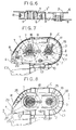
- Fig. 19 shows a relationship between feeding length L of the transfer ribbon fed from the feed core and tension T of the transfer ribbon required for feeding the ribbon from the feed core.
- an adhesive film transfer ribbon R having a total length of about 10m (about 45 micrometers thick) is wound on a feed core 1 having a varied outside diameter "d".
- a radius "r" of each transfer ribbon winding R0 is calculated when every 1m of the transfer ribbon is drawn out.
- a minimum torque M0 necessary for starting rotation of the feed core 1 is fixed to 390gf ⁇ cm.
- the paint film transfer device may further comprise a transfer head in form of a transfer roller movable upstream with respect to a direction of ribbon feeding from the feed core, while pressing a transfer surface of the transfer ribbon upon a receiving surface, the transfer roller having an outside diameter of 8mm to 20mm.
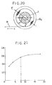
- Fig. 21 shows a relationship between outside diameter Dr of the above transfer roller and coefficient of dynamic friction ⁇ between transfer roller periphery and transfer ribbon.
- the graph of Fig. 21 has been obtained as follows.
- each of transfer rollers 4 has a varied outside diameter Dr in the range of 8mm to 20mm, with an outer peripheral surface having a spring hardness Hs (JISA) set to about 60 degrees.
- Hs spring hardness
- Each transfer roller 4 is fixed, and adhesive film transfer ribbon R (about 45 micrometers thick) is wound on a peripheral surface of the roller with an adhesive film facing outward, at a substantially fixed winding angle ⁇ set to about 90 degrees.
- a weight W of 50gf is suspended from one end of the transfer ribbon R to apply tension T of 50gf to the transfer ribbon R.
- a load cell LS connected to the other end of the transfer ribbon R is moved at a velocity V of about 20mm/sec. in the direction indicated by an arrow.
- the coefficient of dynamic friction ⁇ shows a sharp decrease when the outside diameter Dr of the transfer roller 4 is less than 8mm.
- the transfer ribbon R tends to slip on the outer periphery of the transfer roller 4.
- the coefficient of dynamic friction between the transfer roller and transfer ribbon may be set to a large value to check slippage between the outer periphery of the transfer roller and the transfer ribbon. This enables an efficient transfer operation.
- Fig. 23 shows a relationship between the ratio (Kr/K) of the roller width Kr with respect to the ribbon width K and a minimum pressing force F applied from the transfer roller to a receiving surface as required to draw the transfer ribbon from the feed core.
- an adhesive film transfer device includes a feed core 1 for winding an adhesive film transfer ribbon R (about 45 micrometers thick), a transfer roller 4 for pressing the transfer ribbon R fed from the feed core 1 upon a receiving surface B, and a takeup core 2 for taking up the transfer ribbon R having passed the transfer roller 4.
- the ratio (Kr/K) of the roller width Kr with respect to the ribbon width K is varied, with the tension T required to draw the transfer ribbon R from the feed core 1 being set to about 200gf.
- minimum pressing force F required for transfer at transfer velocity V of about 20mm/sec. is measured while pressing the transfer roller 4 against transfer paper acting as the receiving surface B. Measurements F are plotted in the graph of Fig. 23.
- Fig. 1 is a perspective view of a transfer ribbon cassette according to the present invention.
- Fig. 2 is a plan view showing a mounted state of the transfer ribbon cassette of Fig. 1.
- Fig. 3 is a sectional view showing a mounted state of a principal portion of the transfer ribbon cassette of Fig. 1.
- Fig. 4 is a sectional view showing opening and closing of a case enclosing the transfer ribbon cassette of Fig. 1.
- Fig. 5 is a perspective view showing use of the transfer ribbon cassette of Fig. 1.
- Fig. 6 is a sectional view of a principal portion of a transfer ribbon cassette in another embodiment of the invention.
- Fig. 7 is a plan view showing a mounted state of a transfer ribbon cassette in a further embodiment of the invention.
- Fig. 8 is a plan view showing a mounted state of a transfer ribbon cassette in a still further embodiment of the invention.
- Fig. 9 is a section taken on line I-I of Fig. 8.
- Fig. 10 is a sectional view of a principal portion of the transfer ribbon cassette in the embodiment of Fig. 8 showing a mounted state thereof.
- Fig. 11 is a sectional view of a paint film transfer device in a further embodiment of the invention.
- Fig. 12 is a section taken on line II-II of Fig. 11.
- Fig. 13 is a sectional view of a principal portion of the paint film transfer device of Fig. 11, with a core removed.
- Fig. 14 is a section taken on line III-III of Fig. 13.
- Fig. 15 is a sectional view of a paint film transfer device in a further embodiment of the invention.
- Fig. 16 is a section taken on line IV-IV of Fig. 15.
- Fig. 17 is a section taken on line V-V of Fig. 15.
- Fig. 18 is a plan view showing an open state of split case members shown in Fig. 15.
- Fig. 19 is a graph showing results of calculations made of a relationship between tension and feeding length of a transfer ribbon of a paint film transfer device in a further embodiment of the invention.
- Fig. 20 is a schematic view showing a calculating method.
- Fig. 21 is a graph showing results of experiment conducted for coefficient of dynamic friction and transfer roller diameter of the transfer device of Fig. 19.
- Fig. 22 is a schematic view illustrating the experiment of Fig. 21.
- Fig. 23 is a graph showing results of experiment conducted for required minimum pressing force and transfer roller width/transfer ribbon width in the transfer device of Fig. 19.
- Fig. 24 is a schematic view illustrating the experiment of Fig. 23.
- Fig. 25 is a perspective front view of the transfer device of Fig. 19.
- Fig. 26 is a plan view showing interior of the transfer device of Fig. 19.
- Fig. 27 is a sectional view of a principal portion of the transfer device of Fig. 19.
- Fig. 28 is a perspective view of a prior art example.
- Fig. 1 shows a transfer ribbon cassette A including a transfer ribbon R having an adhesive film D, which is one example of transfer films, applied to one surface thereof.
- the transfer ribbon R is wound around a plastic feed core 1 and a plastic takeup core 2, with the adhesive film D facing outward.
- the cores 1 and 2 are maintained in a predetermined positional relationship by a plastic, plate-like holder 3 to be mountable in a case C.
- the transfer ribbon cassette A further includes a press roller 4 acting as a transfer head for pressing the transfer ribbon R upon a receiving surface B such as of paper to transfer the adhesive film D to the receiving surface B.
- the holder 3 has an outer configuration generally following inner peripheries of the case C for enclosing the transfer ribbon cassette A.
- the holder 3 includes, as integral parts thereof, tongues 7 and 8 for rotatably supporting ends of the cores 1 and 2, perforations 10 for fitting on projections 9 formed on the case C to position the holder 3 relative to the case C, a pawl 11 placed in pressure contact with an inner surface of a peripheral groove 5 of the takeup core 2 to prevent backward rotation of the takeup core 2, second restrictors 12 in the form of a pair of tight and left triangular plates for checking transverse displacement of the transfer ribbon R moving past the press roller 4.
- the holder 3 defines a slot 14 for enabling observation, when the holder 3 is attached to the case C, through a window 13 defined in the case C, of an unused amount of the transfer ribbon R wound on the feed core 1.
- Each of the cores 1 and 2 has a peripheral groove 5 defined adjacent one axial end thereof, and a first restrictor 6 in the form of a circular flange defined at the other axial end for checking displacement toward the other axial end of the transfer ribbon R wound around the core 1 or 2.
- One end of each core 1 or 2 is press fit to the holder 3 while elastically deforming the tongues 7 or 8 in the direction of thickness thereof. Then the tongues 7 or 8 are allowed to fit into the peripheral groove 5 to rotatably support the core 1 or 2 at one end thereof.
- Each of the first restrictors 6 may be in the form of separate pieces extending radially outwardly of the core.
- the second restrictors 12 may be fixed to opposite ends (transversely of the ribbon) of a stationary transfer head.
- the press roller 4 has pins 15 projecting from opposite ends thereof.
- the second restrictors 12 define pin receiving bores for supporting the pins 15, and cutout grooves 16 continuous with the pin receiving bores and slightly narrower than a diameter of the pins 15, respectively.
- the pins 15 are forcibly inserted from a radial direction along the cutout grooves 16 into the pin receiving bores, whereby the opposite ends of the press roller 4 are rotatably supported and retained by the right and left second restrictors 12.
- An intermediate portion of the transfer ribbon R extending from the feed core 1 to the takeup core 2 is wound around the press roller 4.
- Figs. 2 and 3 show a paint film transfer device having the above transfer ribbon cassette A removably mounted in the case C.
- the case C includes two split case members C1 and C2 connected to each other transversely of the transfer ribbon R to be openable and closable through a hinge 17.
- One of the split case members C1 rotatably supports a feeding tubular shaft 18 for fitting in an axial bore of the feed core 1, and a takeup tubular shaft 19 for fitting in an axial bore of the takeup core 2.
- a slip interlock mechanism 39 is provided to interlock the feed core 1 and takeup core 2 such that the takeup core 2 fitted on the takeup tubular shaft 19 is rotatable faster than the feed core 1 fitted on the feeding tubular shaft 18, with slippage allowed between the rotation of the feed core 1 and rotation of the takeup core 2.
- the slip interlock mechanism 39 includes a large diameter pulley 21 formed integral with one end of the feeding tubular shaft 18, a small diameter pulley 22 formed integral with one end of the takeup tubular shaft 19, and an endless transmission belt 20 formed of rubber and wound around the large diameter pulley 21 and small diameter pulley 22.
- the small diameter pulley 22 has a smaller diameter than the large diameter pulley 21 so that ribbon takeup speed of the takeup core 2 is faster than ribbon feed speed of the feed core 1 even when a winding diameter of the transfer ribbon R on the feed core 1 diminishes. Slippage between the transmission belt 20 and small diameter pulley 22 provides slippable interlocking between the rotation of the feed core 1 and rotation of the takeup core 2 to absorb a difference between the ribbon feed speed and ribbon takeup speed.
- the split case members C1 and C2 include engaging craws 33 and 34 for engaging each other when the case members C1 and C2 are closed.
- the holder 3 is held between the two case members C1 and C2. In this state, chattering of the transfer ribbon cassette A is prevented.
- a press portion 35 of the first case member C1 is pressed inward with a thumb or finger, the engaging craws 33 and 34 are disengaged to expose the transfer ribbon cassette A.
- An opening mechanism 36 is provided between the transfer ribbon cassette A and case C.
- the opening mechanism 36 causes the split case members C1 and C2 to pivot relative to each other. Then, this mechanism 36 maintains the engaging craws 33 and 34 out of engagement after removal of the pressure from the press portion 35.
- the opening mechanism 36 includes an elastic piece 37 formed to be elastically deformable in directions of thickness by means of an L-shaped groove cut in the holder 3. Further, a pressing projection 38 is formed integrally with an inner surface of the second split case member C2 for pressing the elastic piece 37 when the split case members C1 and C2 are closed with the transfer ribbon cassette A mounted in between.
- the elastic piece 37 remains elastically deformed under pressure of the pressing projection 38.
- the press portion 35 is pressed to disengage the engaging craws 33 and 34
- the second case member C2 is pushed open by the elastic restoring force of the elastic piece 37.
- the two case members C1 and C2 pivot relative to each other to positions not to permit re-engagement of the engaging craws 33 and 34.
- the projections 9 formed on one of the split case members C1 are fitted in the perforations 10 of the plate-like holder 3 to position the transfer ribbon cassette A relative to the case member C1.
- the transfer ribbon cassette A is attached to the case member C1 with the tubular shafts 18 and 19 fitted into free ends of the cores 1 and 2.
- the case C is closed with the other split case member C2.
- the press roller 4 is moved upstream with respect to a direction of ribbon feeding from the feed core 1, while pressing the adhesive film D of the transfer ribbon R upon the receiving surface B.
- the transfer ribbon R becomes unwound while rotating the feed core 1, and the adhesive film D is transferred to the receiving surface B.
- a used portion of the transfer ribbon R is taken up on the takeup core 2 while making a light and cohesive contact with the adhesive film D of the transfer ribbon R wound on the feed core 1.
- the transfer ribbon cassette A may be attached at the side of the holder 3 to the first split case member C1 supporting the feeding tubular shaft 18 and takeup tubular shaft 19. Then, the free ends of the cores 1 and 2 are rotatably supported by the second split case member C2 upon closure of the case C.
- the holder 3 is held between the two split case members C1 and C2 when the case C is closed, to prevent chattering of the transfer ribbon cassette A.
- at least three projections may be formed integrally with the surface of the holder 3 facing away from the cores 1 and 2.
- the inner surface of the second split case member C2 will press on tip ends of these projections to prevent chattering of the transfer ribbon cassette A.
- the projections may be formed to have varied lengths for the holder 3 to hold cores of different lengths corresponding to transfer ribbons of different widths.
- the same case C may be used for transfer ribbons of different widths.
- the transfer ribbon cassette A may have each of the cores 1 and 2 lightly bonded to the holder 3 to be supported at one end thereof.
- the plate-like holder 3 may include reinforcing ribs formed along peripheral edges thereof.
Abstract
Description
- This invention relates transfer ribbon cassettes. More particularly, the invention relates to a transfer ribbon cassette having a transfer ribbon wound around a feed core and a takeup core maintained in predetermined relative positions by a holder for mounting in a case, the transfer ribbon having a transfer paint film applied to one surface thereof, such as a paint film for use in correcting characters, an adhesive film for bonding purposes or a colored paint film for ornamental use. The invention relates also to a case for enclosing this cassette, and to a paint film transfer device having the cassette.
- A conventional transfer ribbon cassette, as shown in Fig. 28, has a pair of right and
left plates 01 connected to each other throughspacers 05, with a space therebetween corresponding to a ribbon width. A transfer ribbon R is wound around afeed core 02 and atakeup core 03 supported by aholder 04 in the form of a box-like frame. The twocores plates 01, and fixed to a relative positional relationship to be placed in a transfer device case. - Thus, the
holder 04 not only requires numerous materials for manufacture, but has a complicated construction. Its fabrication and assembly of thefeed core 02 and takeupcore 03 are of low productivity, consuming a great deal of time and trouble. Such a transfer ribbon cassette has the disadvantage of high manufacturing cost. - The present invention has been made having regard to the state of the art noted above. A primary object of the present invention, therefore, is to provide a transfer ribbon cassette which may be manufactured at lower cost than the conventional transfer ribbon cassette, with an improved support structure for the feed core and takeup core, as well as a case for enclosing this transfer ribbon cassette.
- A further object of the present invention is to provide a paint film transfer device having the above transfer ribbon cassette and easy to use.
- The above primary object is fulfilled, according to the present invention, by a transfer ribbon cassette as noted at the outset hereof, wherein each of the feed core and takeup core is rotatably supported at one end thereof and, when mounted in the case, has a free axial end thereof supported by the case.
- In the above construction, each core is supported at one end thereof by the holder and at the other end by the case when mounted in the case. Thus, the holder for supporting the feed core and takeup core need not be formed in a box-like frame capable of supporting opposite axial ends of each core.
- As a result, the holder has a simplified construction with less materials required for its manufacture. Its fabrication and assembly of the feed core and takeup core are carried out with greater ease and higher productivity and at less cost than in the prior art.
- Each core may have a first restrictor defined at the free axial end thereof for checking displacement of the transfer ribbon toward the free axial end.
- When the transfer ribbon cassette is attached to the case with the free axial end of each core facing downward, the first restrictor prevents the transfer ribbon from slipping off the core. Even if the transfer ribbon wound around this core should contact the first restrictor, there would be no possibility of an increased resistance being applied to running of the transfer ribbon since the first restrictor is rotatable with the transfer ribbon wound on the core.
- This construction facilitates reliable attachment to the case, requiring only a light operating force.
- The transfer ribbon cassette may further comprise a transfer head for pressing the transfer ribbon upon a receiving surface to transfer the transfer film to the receiving surface, and second restrictors for checking transverse displacement of the transfer ribbon moving past the transfer head, the second restrictors being formed of resin integrally with the holder to support opposite ends of the transfer head transversely of the transfer ribbon.
- This provides a simplified support structure for the transfer head, and allows the transfer ribbon to be wound around the transfer head in advance.
- As a result, the transfer ribbon cassette may be manufactured at still less cost. The transfer ribbon cassette may be assembled to the case quickly and reliably without requiring skill since the transfer ribbon need not be passed around the transfer head in time of assembly.
- The holder may rotatably support one end of each of the feed core and takeup core, such that a portion of the transfer ribbon extending from the feed core to the takeup core is visible through the holder.
- With this construction, when the transfer ribbon cassette is attached to the case with the free end of each core directed toward the case, the portion of the transfer ribbon extending from the feed core to the takeup core may readily be held between a thumb and a finger.
- This facilitates an operation to cause the transfer ribbon to extend along a ribbon guide path in the case, as necessary, when attaching the transfer ribbon cassette to the case.
- In another aspect of the invention, a transfer ribbon cassette as noted in the outset hereof is provided, wherein each core is rotatably supported at one end thereof and, when mounted in the case, has a free axial end thereof supported by the case, the holder being removable from the feed core and takeup core.
- In this construction, when the cores are placed in the case, the free end of each core is supported by the case. Thus, the holder for supporting the feed core and takeup core need not be formed in a box-like frame capable of supporting opposite axial ends of each core. The holder may be removed from the cores when the cores are attached to the case, and hence the holder need not be contained along with the cores in the case.
- As a result, the holder has a simplified construction with less materials required for its manufacture. Its fabrication and assembly of the feed core and takeup core are carried out with greater ease and higher productivity and at less cost than in the prior art. In addition, the case may be formed small.
- Moreover, since the holder is removable from the cores attached to the case, the holder may include a rotation stopper mechanism for the cores, to avoid relaxation of the transfer ribbon without being attached to the case.
- A case for enclosing a transfer ribbon cassette, according to the present invention, comprises an elastic member elastically deformable upon closure of the case, and engaging members for maintaining the case in a closed position. When the engaging members are disengaged, the elastic member returns to an original shape.
- When the engaging members maintaining the case in the closed position are disengaged, the restoring force of the elastic member moves the engaging members to positions not to be engageable.
- This construction has the advantage of facilitating opening of the case, compared with manual opening of the case while disengaging the engaging members.
- A paint film transfer device according to the present invention comprises a slip interlock mechanism including a large diameter pulley rotatable with the feed core, a small diameter pulley rotatable with the takeup core, and a transmission belt wound around the large diameter pulley and the small diameter pulley.
- With this construction, the slip interlock mechanism has no play such as backlash therein. Even when the slip interlock mechanism is moved in either direction while the transfer ribbon cassette is detached from the case, the takeup core rotates with the feed core at an initial stage of rotation of the feed core in a first transfer operation after the transfer ribbon cassette is loaded into the case. Consequently, a used portion of the transfer ribbon in light contact with the transfer ribbon on the feed core has no possibility of moving past a predetermined peeling position to be drawn onto the feed core. The used portion of the transfer ribbon is not relaxed before the takeup core starts taking up the used portion. Thus, the used portion of the transfer ribbon is taken up on the takeup core under suitable tension.
- This construction provides the advantage of reducing the torque of the takeup core necessary for taking up the used portion of the transfer ribbon. At the same time, the used portion of the transfer ribbon to be taken up on the takeup core imparts little resistance to feeding of the transfer ribbon from the feed core during a first transfer operation after the transfer ribbon cassette is loaded into the case. Consequently, the transfer ribbon may run in a normal way, and a used portion of the transfer ribbon may be taken up on the takeup core in a normal way, both from the beginning of a transfer operation.
- The paint film transfer device according to the present invention may include a stationary support shaft for rotatably supporting a tubular shaft which in turn supports a transfer ribbon winding core, and a restrictor formed between the support shaft and tubular shaft for inhibiting the tubular shaft from moving out of the support shaft.
- The transfer ribbon winding core may be removed from the tubular shaft inhibited from moving out of the support shaft. Consequently, the transfer ribbon winding core may be removed from the tubular shaft with ease while the components of the interlock mechanism are retained in interlocked state.
- The restrictor may include engaging members for engaging the support shaft with the tubular shaft, the engaging members being elastically movable to a disengaging position, and a pressing surface for moving the engaging members to the disengaging position during an operation to fit the tubular shaft on the support shaft.
- With this construction, the tubular shaft may be fitted on and engaged with the support shaft in a way to inhibit movement of the tubular shaft out of the support shaft. This paint film transfer device has excellent operability for assembling the tubular shaft to the support shaft.
- In a further aspect of the invention, a paint film transfer device comprises a transfer ribbon cassette including a feed core and a takeup core, each rotatably supported at one end thereof by a plate-like holder, for winding a paint film transfer ribbon, and a case openable and closable for removably containing the transfer ribbon cassette, the case supporting free axial ends of the feed core and the takeup core when the transfer ribbon cassette is mounted therein, wherein the case is divided into a first and a second split case members detachably attachable to each other transversely of the transfer ribbon, the case being openable and closable by attachment and detachment of the first and second split case members, the plate-like holder being disposed between the first and second split case members to check movement of the plate-like holder in directions of thickness thereof.
- When mounted in the case, one end of each core is supported by the plate-like holder, while the other end is supported by one of the split case members. The holder for supporting the feed core and takeup core need not be formed in a box-like frame capable of supporting opposite axial ends of each core. The transfer ribbon cassette may be reduced in size, and the case itself may also be small.
- Even though the plate-like holder may be slightly flexed due to a residual stress or the like produced at manufacturing time, an external force is applied to the plate-like holder in a direction to rectify the flexure when the transfer ribbon cassette is mounted in the case. That is, the plate-like holder is pressed between the two split case members.
- As a result, the holder has a simplified construction, so that the transfer ribbon cassette requires less materials for its manufacture. Its fabrication and assembly of the feed core and takeup core are carried out with great ease. The transfer ribbon cassette and the case may be reduced in size also. Thus, the paint film transfer device according to the present invention requires less manufacturing cost and less transportation cost than in the prior art. Further, the transfer ribbon may run in a trouble-free manner since the feed core and takeup core are reliably maintained in desired postures when the transfer ribbon cassette is mounted in the case.
- The first and second split case members may include reinforcing ribs formed on inner peripheral surfaces thereof for reinforcing the first and second split case members, respectively, the plate-like holder being disposed between the reinforcing ribs to check movement of the plate-like holder in the directions of thickness thereof, the reinforcing ribs formed on at least one of the first and second split case members extending into and contacting the other split case member to check relative displacement between the first and second split case members in directions of thickness of the transfer ribbon.
- The ribs for reinforcing the split case members also serve to check movement of the plate-like holder in the directions of thickness thereof, and to check relative displacement between the first and second split case members in directions of thickness of the transfer ribbon.
- Since the reinforcing ribs extending into the case are utilized to check movement of the plate-like holder in the directions of thickness thereof, no special restrictor is required, thereby promoting simplification of the construction. The reinforcing ribs provide rigidity against external forces acting on the closed split case members in the directions of ribbon thickness.
- In the paint film transfer device, the transfer ribbon may have a substantially entire length feedably wound on the feed core, with an outside diameter (E) of winding of the entire length set to the following ratio with respect to an outside diameter (d) of the feed core:

- Fig. 19 shows a relationship between feeding length L of the transfer ribbon fed from the feed core and tension T of the transfer ribbon required for feeding the ribbon from the feed core. As shown in Fig. 20, an adhesive film transfer ribbon R having a total length of about 10m (about 45 micrometers thick) is wound on a
feed core 1 having a varied outside diameter "d". For varied transfer ribbon windings R0 having different ratios of outside diameter E with respect to the outside diameter "d" of thefeed core 1, a radius "r" of each transfer ribbon winding R0 is calculated when every 1m of the transfer ribbon is drawn out. A minimum torque M0 necessary for starting rotation of thefeed core 1 is fixed to 390gf·cm. Tension T of the transfer ribbon R is derived from the following equation and shown in the graph:

- As seen from the results of calculation, when, with a substantially entire feedable length of the transfer ribbon is wound on the
feed core 1, the ratio (E/d) of outside diameter E of the transfer ribbon winding R0 with respect to the outside diameter "d" of thefeed core 1 exceeds 2.2, tension T of the transfer ribbon required for feeding the ribbon from thefeed core 1 sharply increases with a decrease in the amount of transfer ribbon R wound on thefeed core 1. - Where the ratio (E/d) with respect to the outside diameter "d" of the feed core does not exceed 2.2, the tension of the transfer ribbon necessary for drawing the transfer ribbon from the feed core does not increase greatly over the substantially entire length of the transfer ribbon. This provides excellent operability since the operating feeling is little changed.
- The paint film transfer device may further comprise a transfer head in form of a transfer roller movable upstream with respect to a direction of ribbon feeding from the feed core, while pressing a transfer surface of the transfer ribbon upon a receiving surface, the transfer roller having an outside diameter of 8mm to 20mm.
- Fig. 21 shows a relationship between outside diameter Dr of the above transfer roller and coefficient of dynamic friction µ between transfer roller periphery and transfer ribbon. The graph of Fig. 21 has been obtained as follows.
- As shown in Fig. 22, each of
transfer rollers 4 has a varied outside diameter Dr in the range of 8mm to 20mm, with an outer peripheral surface having a spring hardness Hs (JISA) set to about 60 degrees. Eachtransfer roller 4 is fixed, and adhesive film transfer ribbon R (about 45 micrometers thick) is wound on a peripheral surface of the roller with an adhesive film facing outward, at a substantially fixed winding angle ϑ set to about 90 degrees. A weight W of 50gf is suspended from one end of the transfer ribbon R to apply tension T of 50gf to the transfer ribbon R. A load cell LS connected to the other end of the transfer ribbon R is moved at a velocity V of about 20mm/sec. in the direction indicated by an arrow. The coefficient of dynamic friction µ is derived from the following equation, which disregards centrifugal influences:

where TL is a tension measured with the load cell LS, T is the tension applied by the weight W, and ϑ is the winding angle of the transfer ribbon R. The values thus obtained are plotted in the graph of Fig. 21. - As seen from the results of measurement, the coefficient of dynamic friction µ shows a sharp decrease when the outside diameter Dr of the
transfer roller 4 is less than 8mm. As a result, the transfer ribbon R tends to slip on the outer periphery of thetransfer roller 4. - Thus, the coefficient of dynamic friction between the transfer roller and transfer ribbon may be set to a large value to check slippage between the outer periphery of the transfer roller and the transfer ribbon. This enables an efficient transfer operation.
- The transfer roller may include a peripheral surface having a roller width (kr) set to the following ratio with respect to a width (K) of the transfer ribbon:

- Fig. 23 shows a relationship between the ratio (Kr/K) of the roller width Kr with respect to the ribbon width K and a minimum pressing force F applied from the transfer roller to a receiving surface as required to draw the transfer ribbon from the feed core. As shown in Fig. 24, an adhesive film transfer device includes a
feed core 1 for winding an adhesive film transfer ribbon R (about 45 micrometers thick), atransfer roller 4 for pressing the transfer ribbon R fed from thefeed core 1 upon a receiving surface B, and atakeup core 2 for taking up the transfer ribbon R having passed thetransfer roller 4. The ratio (Kr/K) of the roller width Kr with respect to the ribbon width K is varied, with the tension T required to draw the transfer ribbon R from thefeed core 1 being set to about 200gf. For varied ratios (Kr/K), minimum pressing force F required for transfer at transfer velocity V of about 20mm/sec. is measured while pressing thetransfer roller 4 against transfer paper acting as the receiving surface B. Measurements F are plotted in the graph of Fig. 23. - As seen from the results of measurement, when the ratio (Kr/K) of the roller width Kr with respect to the ribbon width K is less than 1.2, the necessary minimum pressing force F increases sharply.
- When the ratio (Kr/K) of the roller width Kr with respect to the ribbon width K is in the range of 1.2 to 2.5, a small minimum pressing force is required from the transfer roller to the receiving surface to draw the transfer ribbon from the feed core. This enables a transfer operation to be carried out with a light operating force.
- Fig. 1 is a perspective view of a transfer ribbon cassette according to the present invention.
- Fig. 2 is a plan view showing a mounted state of the transfer ribbon cassette of Fig. 1.
- Fig. 3 is a sectional view showing a mounted state of a principal portion of the transfer ribbon cassette of Fig. 1.
- Fig. 4 is a sectional view showing opening and closing of a case enclosing the transfer ribbon cassette of Fig. 1.
- Fig. 5 is a perspective view showing use of the transfer ribbon cassette of Fig. 1.
- Fig. 6 is a sectional view of a principal portion of a transfer ribbon cassette in another embodiment of the invention.
- Fig. 7 is a plan view showing a mounted state of a transfer ribbon cassette in a further embodiment of the invention.
- Fig. 8 is a plan view showing a mounted state of a transfer ribbon cassette in a still further embodiment of the invention.
- Fig. 9 is a section taken on line I-I of Fig. 8.
- Fig. 10 is a sectional view of a principal portion of the transfer ribbon cassette in the embodiment of Fig. 8 showing a mounted state thereof.
- Fig. 11 is a sectional view of a paint film transfer device in a further embodiment of the invention.
- Fig. 12 is a section taken on line II-II of Fig. 11.
- Fig. 13 is a sectional view of a principal portion of the paint film transfer device of Fig. 11, with a core removed.
- Fig. 14 is a section taken on line III-III of Fig. 13.
- Fig. 15 is a sectional view of a paint film transfer device in a further embodiment of the invention.
- Fig. 16 is a section taken on line IV-IV of Fig. 15.
- Fig. 17 is a section taken on line V-V of Fig. 15.
- Fig. 18 is a plan view showing an open state of split case members shown in Fig. 15.
- Fig. 19 is a graph showing results of calculations made of a relationship between tension and feeding length of a transfer ribbon of a paint film transfer device in a further embodiment of the invention.
- Fig. 20 is a schematic view showing a calculating method.
- Fig. 21 is a graph showing results of experiment conducted for coefficient of dynamic friction and transfer roller diameter of the transfer device of Fig. 19.
- Fig. 22 is a schematic view illustrating the experiment of Fig. 21.
- Fig. 23 is a graph showing results of experiment conducted for required minimum pressing force and transfer roller width/transfer ribbon width in the transfer device of Fig. 19.
- Fig. 24 is a schematic view illustrating the experiment of Fig. 23.
- Fig. 25 is a perspective front view of the transfer device of Fig. 19.
- Fig. 26 is a plan view showing interior of the transfer device of Fig. 19.
- Fig. 27 is a sectional view of a principal portion of the transfer device of Fig. 19.
- Fig. 28 is a perspective view of a prior art example.
- Transfer ribbon cassettes embodying the present invention will be described in detail with reference to the drawings.
- Fig. 1 shows a transfer ribbon cassette A including a transfer ribbon R having an adhesive film D, which is one example of transfer films, applied to one surface thereof. The transfer ribbon R is wound around a
plastic feed core 1 and aplastic takeup core 2, with the adhesive film D facing outward. Thecores like holder 3 to be mountable in a case C. The transfer ribbon cassette A further includes apress roller 4 acting as a transfer head for pressing the transfer ribbon R upon a receiving surface B such as of paper to transfer the adhesive film D to the receiving surface B. - As shown in Figs. 1 and 2, the
holder 3 has an outer configuration generally following inner peripheries of the case C for enclosing the transfer ribbon cassette A. Theholder 3 includes, as integral parts thereof,tongues cores perforations 10 for fitting onprojections 9 formed on the case C to position theholder 3 relative to the case C, apawl 11 placed in pressure contact with an inner surface of aperipheral groove 5 of thetakeup core 2 to prevent backward rotation of thetakeup core 2,second restrictors 12 in the form of a pair of tight and left triangular plates for checking transverse displacement of the transfer ribbon R moving past thepress roller 4. Further, theholder 3 defines aslot 14 for enabling observation, when theholder 3 is attached to the case C, through awindow 13 defined in the case C, of an unused amount of the transfer ribbon R wound on thefeed core 1. - Each of the
cores peripheral groove 5 defined adjacent one axial end thereof, and afirst restrictor 6 in the form of a circular flange defined at the other axial end for checking displacement toward the other axial end of the transfer ribbon R wound around thecore holder 3 while elastically deforming thetongues tongues peripheral groove 5 to rotatably support thecore first restrictors 6 may be in the form of separate pieces extending radially outwardly of the core. Thesecond restrictors 12 may be fixed to opposite ends (transversely of the ribbon) of a stationary transfer head. - The
press roller 4 haspins 15 projecting from opposite ends thereof. Thesecond restrictors 12 define pin receiving bores for supporting thepins 15, andcutout grooves 16 continuous with the pin receiving bores and slightly narrower than a diameter of thepins 15, respectively. Thepins 15 are forcibly inserted from a radial direction along thecutout grooves 16 into the pin receiving bores, whereby the opposite ends of thepress roller 4 are rotatably supported and retained by the right and leftsecond restrictors 12. An intermediate portion of the transfer ribbon R extending from thefeed core 1 to thetakeup core 2 is wound around thepress roller 4. - Figs. 2 and 3 show a paint film transfer device having the above transfer ribbon cassette A removably mounted in the case C. The case C includes two split case members C1 and C2 connected to each other transversely of the transfer ribbon R to be openable and closable through a
hinge 17. One of the split case members C1 rotatably supports a feedingtubular shaft 18 for fitting in an axial bore of thefeed core 1, and a takeuptubular shaft 19 for fitting in an axial bore of thetakeup core 2. Aslip interlock mechanism 39 is provided to interlock thefeed core 1 andtakeup core 2 such that thetakeup core 2 fitted on the takeuptubular shaft 19 is rotatable faster than thefeed core 1 fitted on the feedingtubular shaft 18, with slippage allowed between the rotation of thefeed core 1 and rotation of thetakeup core 2. - The
slip interlock mechanism 39 includes alarge diameter pulley 21 formed integral with one end of the feedingtubular shaft 18, asmall diameter pulley 22 formed integral with one end of the takeuptubular shaft 19, and anendless transmission belt 20 formed of rubber and wound around thelarge diameter pulley 21 andsmall diameter pulley 22. Thesmall diameter pulley 22 has a smaller diameter than thelarge diameter pulley 21 so that ribbon takeup speed of thetakeup core 2 is faster than ribbon feed speed of thefeed core 1 even when a winding diameter of the transfer ribbon R on thefeed core 1 diminishes. Slippage between thetransmission belt 20 andsmall diameter pulley 22 provides slippable interlocking between the rotation of thefeed core 1 and rotation of thetakeup core 2 to absorb a difference between the ribbon feed speed and ribbon takeup speed. - As shown in Fig. 4, the split case members C1 and C2 include engaging
craws holder 3 is held between the two case members C1 and C2. In this state, chattering of the transfer ribbon cassette A is prevented. When apress portion 35 of the first case member C1 is pressed inward with a thumb or finger, the engagingcraws - An
opening mechanism 36 is provided between the transfer ribbon cassette A and case C. When the engagingcraws press portion 35, theopening mechanism 36 causes the split case members C1 and C2 to pivot relative to each other. Then, thismechanism 36 maintains the engagingcraws press portion 35. - The
opening mechanism 36 includes anelastic piece 37 formed to be elastically deformable in directions of thickness by means of an L-shaped groove cut in theholder 3. Further, apressing projection 38 is formed integrally with an inner surface of the second split case member C2 for pressing theelastic piece 37 when the split case members C1 and C2 are closed with the transfer ribbon cassette A mounted in between. When the split case members C1 and C2 are closed and the engagingcraws elastic piece 37 remains elastically deformed under pressure of thepressing projection 38. When thepress portion 35 is pressed to disengage the engagingcraws elastic piece 37. As a result, the two case members C1 and C2 pivot relative to each other to positions not to permit re-engagement of the engagingcraws - With the case C opened, the
projections 9 formed on one of the split case members C1 are fitted in theperforations 10 of the plate-like holder 3 to position the transfer ribbon cassette A relative to the case member C1. The transfer ribbon cassette A is attached to the case member C1 with thetubular shafts cores press roller 4 is moved upstream with respect to a direction of ribbon feeding from thefeed core 1, while pressing the adhesive film D of the transfer ribbon R upon the receiving surface B. The transfer ribbon R becomes unwound while rotating thefeed core 1, and the adhesive film D is transferred to the receiving surface B. A used portion of the transfer ribbon R is taken up on thetakeup core 2 while making a light and cohesive contact with the adhesive film D of the transfer ribbon R wound on thefeed core 1. - The transfer ribbon cassette A may be attached at the side of the
holder 3 to the first split case member C1 supporting the feedingtubular shaft 18 and takeuptubular shaft 19. Then, the free ends of thecores - In the above embodiment, the
holder 3 is held between the two split case members C1 and C2 when the case C is closed, to prevent chattering of the transfer ribbon cassette A. Alternatively, at least three projections may be formed integrally with the surface of theholder 3 facing away from thecores - With this construction, the projections may be formed to have varied lengths for the
holder 3 to hold cores of different lengths corresponding to transfer ribbons of different widths. Thus, the same case C may be used for transfer ribbons of different widths. - The transfer ribbon cassette A may have each of the
cores holder 3 to be supported at one end thereof. - The plate-
like holder 3 may include reinforcing ribs formed along peripheral edges thereof. - Other embodiments will be described next.
- (1) As shown in Fig. 6, a holder 3' Z-shaped as seen radially thereof may be used for rotatably supporting one end of each of the
cores cores - (2) Fig. 7 shows a transfer ribbon cassette A mounted in a case C having a
transfer head 4 formed integral with a first split case member C1. The plate-like holder 3 has an engagingpiece 23 formed integral therewith for engaging a portion of the transfer ribbon R extending from thefeed core 1 to thetakeup core 2. The transfer ribbon R is visible through theholder 3.
According to the transfer ribbon cassette A in this embodiment, after the transfer ribbon cassette A is attached to the case C with the free ends of thecores tubular shafts feed core 1 to thetakeup core 2 with his or her thumb and finger, and place that portion around thetransfer head 4. Then, the transfer ribbon R extends along a ribbon guide path in the case C. - (3) Figs. 8 and 9 show a transfer ribbon cassette A mounted in a case C having a
transfer head 4 formed integral with a first split case member C1. A plate-like holder 3 supports one end of each of afeed core 1 and atakeup core 2 not to be rotatable. When thecores tubular shafts cores
Theholder 3 includes twotongues tubular projections 26 formed integral with thetongues feed core 1 andtakeup core 2 are press fit in thetubular projections tongues cores cores tubular projections cores holder 3 may be detached from thecores
Theholder 3 includes astretcher 29 formed integral therewith for stretching a portion of the transfer ribbon R extending from thefeed core 1 to thetakeup core 2 along a ribbon guide path in the case C. Thus, thestretcher 29 is detachable with theholder 3, leaving thecores
Thestretcher 29 includes a curvedengaging plate 30 around which the transfer ribbon R is wound, and anarm 31 for supporting the engagingplate 30 with a predetermined space therebetween.
As shown in Fig. 8, when the transfer ribbon cassette A is attached to the case C, the transfer ribbon R is guided close to thetransfer head 4. When, in this state, theholder 3 is detached along with thestretcher 29 from thecores cores members 32 formed integral with the second split case member C2. - (4) The large diameter pulley rotatable with the feed core may be formed separately from and assembled to the feed core. Similarly, the small diameter pulley rotatable with the takeup core may be formed separately from and assembled to the takeup core.
- (5) Figs. 11 and 12 show a different case C of the paint film transfer device.
The case C includes two split case members C1 and C2 connected to each other transversely of the transfer ribbon R to be openable and closable through ahinge 17. One of the split case members C1 has a firsttubular support shaft 46 and a secondtubular support shaft 47 formed integral with the case member C1. The feedingtubular shaft 18 is rotatably supported by thefirst support shaft 46. The takeuptubular shaft 19 is rotatably supported by thesecond support shaft 47.
Thefeed core 1 of the transfer ribbon cassette A is removably mounted on the feedingtubular shaft 18 to be rotatable therewith. Thetakeup core 2 of the transfer ribbon cassette A is removably mounted on the takeuptubular shaft 19 to be rotatable therewith.
Alarge diameter pulley 21 is formed integral with a proximal end of the feedingtubular shaft 18 adjacent the split case member C1. Asmall diameter pulley 22 is formed integral with a proximal end of the takeuptubular shaft 19 adjacent the split case member C1. Atransmission belt 20 is wound around thelarge diameter pulley 21 andsmall diameter pulley 22. Thebelt 20 andpulleys slip interlock mechanism 39 for rotating thefeed core 1 andtakeup core 2 with running of the transfer ribbon R.
When thepress roller 4 is moved while pressing an adhesive film D of the transfer ribbon R upon a receiving surface B, the transfer ribbon R runs with the adhesive film D transferred to the receiving surface B. At this time, the transfer ribbon R rotates thefeed core 1, and a used portion of the transfer ribbon R is taken up on thetakeup core 2 also in rotation.
As shown in Fig. 12, the split case members C1 and C2 include engagingcraws holder 3 is held between the two case members C1 and C2 to prevent chattering of the transfer ribbon cassette A. When apress portion 35 of the first case member C1 is pressed inward with a thumb or finger, the engagingcraws device 50 is formed between thefirst support shaft 46 and feedingtubular shaft 18 for engaging thefirst support shaft 46 with the feedingtubular shaft 18. The engagingdevice 50 is elastically movable to a disengaging position. The engagingdevice 50 provides a restrictor 49 for inhibiting the feedingtubular shaft 18 from moving out of thefirst support shaft 46.
The engagingdevice 50 includes slit-like cutouts 57 formed in two positions of thefirst support shaft 46 opposed to each other across an axis thereof and extending axially of thefirst support shaft 46, andprojections 46b formed peripherally of a pair ofshaft portions 46a divided by the twocutouts 57. Theprojections 46b are situated in axially intermediate positions at the same distance from a tip end of thefirst support shaft 46. The disengaging position noted above is provided by elastically tilting deformation toward the axis of theshaft portions 46a.
The feedingtubular shaft 18 defines abore 48 for receiving thefirst support shaft 46. Thebore 48 includes asmall diameter portion 48a opposed to the split case member C1, and alarge diameter portion 48b opposed to the plate-like holder 3. The feedingtubular shaft 18 includes ashoulder 48 in an axially intermediate position thereof. Apressing surface 41 is formed in thesmall diameter portion 48a for moving the engagingdevice 50 to the disengaging position when the feedingtubular shaft 18 is pushed onto thefirst support shaft 46.
The feedingtubular shaft 18 supported by thefirst support shaft 46 is inhibited from moving out of thefirst support shaft 46 by engagement between the twoprojections 46b of thefirst support shaft 46 and theshoulder 48c of the feedingtubular shaft 18.
Specifically, thesmall diameter portion 48a of the feedingtubular shaft 18 is fitted on the tip end of thefirst support shaft 46. In this state, the feedingtubular shaft 18 is pushed toward the split case member C1. Then, thepressing surface 41 contacts theprojections 46b. As the feedingtubular shaft 18 is pushed further, theshaft portions 46a is pressed by thepressing surface 41 to tilt toward the axis. Theprojections 46b elastically move to the disengaging position, and enter thesmall diameter portion 48a. When theshoulder 48c of the feedtubular shaft 18 moves past theprojections 46b, theshaft portions 46a elastically return away from the axis to engage theprojections 46b with theshoulder 48c.
In this state, the feedingtubular shaft 18 is inhibited from moving out of thefirst support shaft 46, while being rotatably supported by thefirst support shaft 46.
The transfer ribbon may have a transfer paint film for use in correcting characters or a colored paint film for ornamental use. The transfer film is not limited to a particular type, function or use.
The support shaft may have a flanged plug or the like fitted or screwed into the tip end thereof. The flange will then act as a restrictor for contacting the tubular shaft to prevent the tubular shaft from moving out of the support shaft.
The restrictor may have an engaging device formed on the tubular shaft.
The interlock mechanism may be a gear type mechanism.
The second support shaft and takeup tubular shaft may have a restrictor for inhibiting the takeup tubular shaft from moving out of the second support shaft.
The projections formed on the shaft portions of the first support shaft may extend circumferentially of the shaft portions. - (6) A further embodiment will be described.
As shown in Fig. 18, aholder 3 has an outer configuration generally following inner peripheries of a case C. Theholder 3 includestongues cores holder 3 further includes, as integral parts thereof,perforations 10 for fitting onprojections 9 formed on the case C to position theholder 3 relative to the case C, andsecond restrictors 12 in the form of a pair of right and left triangular plates for checking transverse displacement of a transfer ribbon R moving past apress roller 4.
As shown in Figs. 15 through 18, each of thecores peripheral groove 5 defined adjacent one axial end thereof, and afirst restrictor 6 in the form of a circular flange defined at the other axial end for checking displacement toward the other axial end of the transfer ribbon R wound around thecore like holder 3, one end of each core 1 or 2 is press fit to theholder 3 while elastically deforming thetongues tongues peripheral groove 5 to rotatably support thecore
Thepress roller 4 haspins 15 projecting from opposite ends thereof and rotatably supported by thesecond restrictors 12. An intermediate portion of the transfer ribbon R extending from thefeed core 1 to thetakeup core 2 is wound around thepress roller 4.
The case C, in which the transfer ribbon cassette A having the above construction is removably mounted, includes split case members C1 and C2 connected to each other transversely of the transfer ribbon R to be openable and closable through ahinge 17. The first split case member C1 includes afirst support shaft 46 for rotatably supporting a feedingtubular shaft 18 for fitting in an axial bore of thefeed core 1, and asecond support shaft 47 for rotatably supporting a takeuptubular shaft 19 for fitting in an axial bore of thetakeup core 2. Atransmission belt 20 is wound around the feedingtubular shaft 18 and takeuptubular shaft 19.
Thetransmission belt 20 interlocks thefeed core 1 engaged with the feedingtubular shaft 18 and thetakeup core 2 engaged with the takeuptubular shaft 19. As the transfer ribbon R is drawn to rotate thefeed core 1, a used portion of the transfer ribbon R is taken up on thetakeup core 2.
The split case members C1 and C2 include reinforcingribs ribs 59 of the first case member C1 extend into the second case member C2. Peripheries of the plate-like holder 3 lie between the reinforcingribs holder 3 in directions of its thickness.
Specifically, when the case C is closed, gaps slightly larger than a thickness of the plate-like holder 3 are formed between opposed end surfaces ofextensions 59a of the reinforcingribs 59 formed on the first case member C1 and the reinforcingribs 60 formed on the second case member C2. The end surfaces of the reinforcingribs like holder 3 act as restrictor surfaces for checking movement of the plate-like holder 3 in the directions of its thickness.
Theextensions 59a of the reinforcingribs 59 contact inner peripheral edges of the second case member C2 when the two case members C1 and C2 are closed, to check relative displacement between the case members C1 and C2 in directions of thickness of the transfer ribbon R.
As shown in Fig. 17, the first split case member C1 includes an engagingcraw 33 while the second split case member C2 includes an engagingcraw 34. When the two case members C1 and C2 are closed, the engagingcraw 33 engages the engagingcraw 34 to maintain the two case members C1 and C2 closed.
When apress portion 35 of the first case member C1 is pressed inward with a thumb or finger, the engagingcraws
Anopening mechanism 36 is provided between the transfer ribbon cassette A and case C. When the engagingcraws press portion 35, theopening mechanism 36, by means of its elastic force, opens the split case members C1 and C2.
Theopening mechanism 36 includes anelastic piece 37 formed to be elastically deformable in the directions of thickness by means of an L-shaped groove cut in the plate-like holder 3. Further, apressing projection 38 is formed integrally with an inner surface of the second split case member C2 for pressing theelastic piece 37 when the split case members C1 and C2 are closed with the transfer ribbon cassette A mounted in between.
When the split case members C1 and C2 are closed and the engagingcraws elastic piece 37 remains elastically deformed under pressure of thepressing projection 38. When thepress portion 35 is pressed to disengage the engagingcraws craws
With the case C opened, theprojections 9 formed on the first split case members C1 are fitted in theperforations 10 of the plate-like holder 3 to position the transfer ribbon cassette A relative to the case member C1. The transfer ribbon cassette A is attached to the case C with thetubular shafts cores
In this state, the free axial ends of thecores tubular shafts support shafts
After the case C is closed, thepress roller 4 may be moved while pressing the adhesive film D of the transfer ribbon R upon a receiving surface B. Then, the transfer ribbon R becomes unwound while rotating thefeed core 1, and the adhesive film D is transferred to the receiving surface B. A used portion of the transfer ribbon R is taken upon thetakeup core 2.
The transfer ribbon cassette A may be mounted in a case C consisting of split case members C1 and C2 with no reinforcing ribs. In this case, the two split case members C1 and C2 may include a restrictor formed on inner surfaces thereof exclusively for checking movement of the plate-like holder 3 in the directions of its thickness.
Even where the split case members C1 and C2 have the reinforcingribs ribs like holder 3 in the directions of its thickness. Further, the plate-like holder 3 may be prevented from moving in the directions of its thickness by the reinforcing ribs of the first split case member and a special restrictor provided on the second split case member.
The transfer ribbon cassette may have a transfer ribbon with a transfer paint film for use in correcting characters or a colored paint film for ornamental use. The transfer film is not limited to a particular type, function or use. - (7) A further embodiment will be described.
A paint film transfer device in this embodiment includes an unused transfer ribbon R having a total length of about 10m wound as transfer ribbon winding R0 on afeed core 1. The transfer ribbon winding R0 of a substantially entire length of the transfer ribbon R has an outside diameter E in the ratio (E/d) not exceeding 2.2 (1.4 in this embodiment) with respect to an outside diameter "d" of thefeed core 1. Apress roller 4 has an outside diameter Dr in the range of 8mm to 20mm (9mm in the embodiment), with an outer peripheral surface having a spring hardness Hs (JISA) set to about 60 degrees. Further, thepress roller 4 has a peripheral roller width Kr in the ratio (kr/K) of 1.2 to 2.5 (1.5 in the embodiment) with respect to width K of the transfer ribbon R.
Aholder 3 has an outer configuration generally following inner peripheries of a case C to which theholder 3 is attached, and rotatably supports ends ofcores holder 3 further includes, as integral parts thereof,perforations 10 for fitting onprojections 9 formed on the case C to position theholder 3 relative to the case C, apawl 11 for preventing backward rotation of thetakeup core 2, andsecond restrictors 12 in the form of a pair of right and left triangular plates for checking transverse displacement of the transfer ribbon R moving past thepress roller 4.
Thepress roller 4 has opposite ends thereof transversely of the transfer ribbon R rotatably supported by thesecond restrictors 12. A portion of the transfer ribbon R extending from thefeed core 1 to thetakeup core 2 is wound around thepress roller 4.
Figs. 26 and 27 show a paint film transfer device A0 having the above transfer ribbon cassette A removably mounted in the case C. The case C includes two split case members C1 and C2 connected to each other transversely of the transfer ribbon R to be openable and closable. The first split case member C1 rotatably supports a feedingtubular shaft 18 for fitting in an axial bore of thefeed core 1, and a takeuptubular shaft 19 for fitting in an axial bore of thetakeup core 2. Aslip interlock mechanism 39 is provided to interlock thefeed core 1 andtakeup core 2 such that thetakeup core 2 fitted on the takeuptubular shaft 19 is rotatable faster than thefeed core 1 fitted on the feedingtubular shaft 18, with slippage allowed between the rotation of thefeed core 1 and rotation of thetakeup core 2.
Theslip interlock mechanism 39 includes alarge diameter pulley 21 formed integral with one end of the feedingtubular shaft 18, asmall diameter pulley 22 formed integral with one end of the takeuptubular shaft 19, and anendless transmission belt 20 formed of rubber and wound around thelarge diameter pulley 21 andsmall diameter pulley 22. Thesmall diameter pulley 22 has a smaller diameter than thelarge diameter pulley 21 so that ribbon takeup speed of thetakeup core 2 is faster than ribbon feed speed of thefeed core 1 even when the outside diameter E of the transfer ribbon winding R0 on thefeed core 1 diminishes with use of the transfer ribbon R. Slippage between thetransmission belt 20 andsmall diameter pulley 22 provides slippable interlocking between the rotation of thefeed core 1 and rotation of thetakeup core 2 to absorb a difference between the ribbon feed speed and ribbon takeup speed.
Setting is made in advance so that slippage occurs between thetransmission belt 20 andsmall diameter pulley 22 when thefeed core 1 is subjected to a torque M0 of about 390gf·cm or more.
With the case C opened, theprojections 9 formed on the first split case member C1 are fitted in theperforations 10 of the plate-like holder 3 to position the transfer ribbon cassette A relative to the case member C1. The transfer ribbon cassette A is attached to the case member C1 with thetubular shafts cores press roller 4 is moved upstream with respect to a direction of ribbon feeding from thefeed core 1, while pressing an adhesive film D of the transfer ribbon R upon the receiving surface B. The transfer ribbon R becomes unwound while rotating thefeed core 1, and the adhesive film D is transferred to the receiving surface B. A used portion of the transfer ribbon R is taken up on thetakeup core 2 while making a light and cohesive contact with the adhesive film D of the transfer ribbon R wound on thefeed core 1. - (8) The paint film transfer device may be used for transferring to a receiving surface a transfer film for correcting characters or a colored paint film for ornamental use. Further, the transfer device may be used for transferring a heat sensitive transfer film as well as a pressure sensitive transfer film. The transfer film is not limited to a particular type, function or use.
Claims (20)
- A transfer ribbon cassette comprising:
a feed core for winding a transfer ribbon having a transfer film applied to one surface thereof;
a takeup core for taking up said transfer ribbon fed from said feed core; and
a holder for holding said feed core and said takeup core in a relative positional relationship for mounting in a case;
wherein each of said feed core and said takeup core is rotatably supported at one end thereof and, when mounted in said case, has a free axial end thereof supported by said case. - A transfer ribbon cassette as defined in claim 1, wherein each of said feed core and said takeup core has first restrictor means defined at said free axial end thereof for checking displacement of said transfer ribbon toward said free axial end.
- A transfer ribbon cassette as defined in claim 1, further comprising a transfer head for pressing said transfer ribbon upon a receiving surface to transfer said transfer film to said receiving surface, and second restrictor means for checking transverse displacement of said transfer ribbon moving past said transfer head, said second restrictor means being formed of resin integrally with said holder, and supporting opposite ends of said transfer head transversely of said transfer ribbon.
- A transfer ribbon cassette as defined in claim 1, wherein said holder rotatably supports one end of each of said feed core and said takeup core, such that a portion of said transfer ribbon extending from said feed core to said takeup core is visible through said holder.
- A transfer ribbon cassette as defined in claim 1, wherein said holder is Z-shaped as seen radially thereof for rotatably supporting one end of each said feed core and said takeup core arranged radially, said feed core and said takeup core being supported on a front surface and a back surface of said holder, respectively.
- A transfer ribbon cassette comprising:
a feed core for winding a transfer ribbon having a transfer film applied to one surface thereof;
a takeup core for taking up said transfer ribbon fed from said feed core; and
a holder for holding said feed core and said takeup core in a relative positional relationship for mounting in a case;
wherein each of said feed core and said takeup core is rotatably supported at one end thereof and, when mounted in said case, has a free axial end thereof supported by said case, said holder being removable from said feed core and said takeup core. - A transfer ribbon cassette as defined in claim 6, wherein said holder includes stretcher means formed integral therewith for stretching a portion of said transfer ribbon extending from said feed core to said takeup core along a ribbon guide path in said case, said stretcher means including a curved engaging plate around which said transfer ribbon is wound, and an arm for supporting said engaging plate at a predetermined space therebetween.
- A case comprising:
a first split case member for supporting a transfer ribbon cassette;
a second split case member for enclosing said transfer ribbon cassette in combination with said first split case member;
an elastic member formed on one of said first split case member and said second split case member to be elastically deformable with closing of said split case members; and
engaging means for maintaining said split case members in a closed position. - A case as defined in claim 8, wherein said first split case member includes a transfer head for pressing a transfer ribbon upon a receiving surface to press an adhesive surface of said transfer ribbon upon said receiving surface.
- A paint film transfer device comprising:
a transfer ribbon cassette containing:
a feed core for winding a transfer ribbon having a transfer film applied to one surface thereof;
a transfer head for pressing said transfer ribbon fed from said feed core upon a receiving surface; and
a takeup core for taking up said transfer ribbon having passed through said transfer head, while allowing said transfer ribbon to contact said transfer film of said transfer ribbon wound on said feed core; and
a case for removably enclosing said transfer ribbon cassette, said case including:
a slip interlock mechanism for interlocking said feed core and said takeup core such that said takeup core is rotatable faster than said feed core, with slippage allowed between rotation of said feed core and rotation of said takeup core;
said transfer ribbon becoming unwound while rotating said feed core, with a used portion of said transfer ribbon having passed through said transfer head being taken up on said takeup core when said transfer head is moved upstream with respect to a direction of ribbon feeding from said feed core, while pressing said transfer ribbon upon said receiving surface;
wherein said slip interlock mechanism includes a large diameter pulley rotatable with said feed core, a small diameter pulley rotatable with said takeup core, and a transmission belt wound around said large diameter pulley and said small diameter pulley. - A paint film transfer device comprising:
a case including a first split case member and a second split case member; and
a transfer ribbon cassette containing:
a feed core;
a takeup core combined with said feed core for winding a transfer ribbon having a transfer film applied to one surface thereof; and
a holder for holding said feed core and said takeup core in a relative positional relationship for mounting in said case;
wherein said case contains a stationary shaft for rotatably supporting a tubular shaft, said feed core being removably mounted on said tubular shaft to be rotatable therewith; a slip interlock mechanism for rotating said tubular shaft with running of said transfer ribbon; and restrictor means formed between said support shaft and said tubular shaft for inhibiting said tubular shaft from moving out of said support shaft. - A paint film transfer device as defined in claim 11, wherein said restrictor means includes engaging means for engaging said support shaft with said tubular shaft, said engaging means being elastically movable to a disengaging position, and a pressing surface for moving said engaging means to said disengaging position during an operation to fit said tubular shaft on said support shaft.
- A paint film transfer device comprising:
a transfer ribbon cassette including a feed core and a takeup core, each rotatably supported at one end thereof by a plate-like holder, for winding a paint film transfer ribbon; and
a case openable and closable for removably containing said transfer ribbon cassette, said case supporting free axial ends of said feed core and said takeup core when said transfer ribbon cassette is mounted therein;
wherein said case is divided into a first and a second split case members detachably attachable to each other transversely of said transfer ribbon, said case being openable and closable by attachment and detachment of said first and second split case members, said plate-like holder being disposed between said first and second split case members to check movement of said plate-like holder in directions of thickness thereof. - A paint film transfer device as defined in claim 13, wherein said first and second split case members include reinforcing ribs formed on inner peripheral surfaces thereof for reinforcing said first and second split case members, respectively, said plate-like holder being disposed between said reinforcing ribs to check movement of said plate-like holder in the directions of thickness thereof, the reinforcing ribs formed on at least one of said first and second split case members extending into and contacting the other split case member to check relative displacement between said first and second split case members in directions of thickness of said transfer ribbon.
- A paint film transfer device as defined in claim 13, wherein said transfer ribbon has a substantially entire length feedably wound on said feed core, with an outside diameter (E) of winding of said entire length set to the following ratio with respect to an outside diameter (d) of said feed core:

- A paint film transfer device as defined in claim 13, further comprising a transfer head in form of a transfer roller movable upstream with respect to a direction of ribbon feeding from said feed core, while pressing a transfer surface of said transfer ribbon upon a receiving surface, said transfer roller having an outside diameter of 8mm to 20mm.
- A paint film transfer device as defined in claim 13, further comprising a transfer roller including a peripheral surface having a roller width (kr) set to the following ratio with respect to a width (K) of said transfer ribbon:

- A paint film transfer device comprising:
a feed core for winding a transfer ribbon to form transfer ribbon winding;
a transfer head for pressing said transfer ribbon fed from said feed core upon a receiving surface;
a takeup core for taking up said transfer ribbon having passed through said transfer head; and
a slip interlock mechanism for interlocking said feed core and said takeup core such that said takeup core is rotatable faster than said feed core, with slippage allowed between rotation of said feed core and rotation of said takeup core;
said transfer ribbon becoming unwound while rotating said feed core, with a used portion of said transfer ribbon having passed through said transfer head being taken up on said takeup core when said transfer head is moved upstream with respect to a direction of ribbon feeding from said feed core, while pressing said transfer ribbon upon said receiving surface;
wherein said transfer ribbon has a substantially entire length feedably wound on said feed core, with an outside diameter (E) of winding of said entire length set to the following ratio with respect to an outside diameter (d) of said feed core:

- A paint film transfer device as defined in claim 18, wherein said transfer head is in form of a transfer roller movable upstream with respect to the direction of ribbon feeding from said feed core, while pressing a transfer surface of said transfer ribbon upon said receiving surface, said transfer roller having an outside diameter of 8mm to 20mm.
- A paint film transfer device as defined in claim 18, wherein said transfer roller includes a peripheral surface having a roller width (kr) set to the following ratio with respect to a width (K) of said transfer ribbon:

Applications Claiming Priority (10)
| Application Number | Priority Date | Filing Date | Title |
|---|---|---|---|
| JP7943793A JPH06286927A (en) | 1993-04-06 | 1993-04-06 | Decalcomania ribbon cassette and case for mounting this cassette |
| JP79437/93 | 1993-04-06 | ||
| JP219491/93 | 1993-09-03 | ||
| JP21949193A JP3441490B2 (en) | 1993-09-03 | 1993-09-03 | Paint transfer tool |
| JP22408993A JP3400030B2 (en) | 1993-09-09 | 1993-09-09 | Paint transfer tool |
| JP224089/93 | 1993-09-09 | ||
| JP22992693A JPH0781826A (en) | 1993-09-16 | 1993-09-16 | Coating film transferring tool |
| JP229926/93 | 1993-09-16 | ||
| JP244934/93 | 1993-09-30 | ||
| JP24493493A JPH0797113A (en) | 1993-09-30 | 1993-09-30 | Film transfer tool |
Publications (3)
| Publication Number | Publication Date |
|---|---|
| EP0619189A2 true EP0619189A2 (en) | 1994-10-12 |
| EP0619189A3 EP0619189A3 (en) | 1995-08-23 |
| EP0619189B1 EP0619189B1 (en) | 1999-01-27 |
Family
ID=27524788
Family Applications (1)
| Application Number | Title | Priority Date | Filing Date |
|---|---|---|---|
| EP94105272A Expired - Lifetime EP0619189B1 (en) | 1993-04-06 | 1994-04-05 | Transfer ribbon cassette, a case for enclosing the cassette and a paint film transfer device having the same |
Country Status (3)
| Country | Link |
|---|---|
| US (1) | US5499877A (en) |
| EP (1) | EP0619189B1 (en) |
| DE (1) | DE69416182T2 (en) |
Cited By (15)
| Publication number | Priority date | Publication date | Assignee | Title |
|---|---|---|---|---|
| EP0679597A2 (en) * | 1994-04-28 | 1995-11-02 | Fujicopian Co., Ltd. | Film transfer apparatus and a film transfer roller used therein |
| EP0695645A1 (en) * | 1994-08-01 | 1996-02-07 | Fujicopian Co., Ltd. | Film transfer apparatus |
| EP0717000A2 (en) * | 1994-12-12 | 1996-06-19 | Seed Rubber Company Ltd. | Tape cartridge for coating film transfer tool and coating film transfer tool |
| EP0755889A1 (en) * | 1995-07-24 | 1997-01-29 | Fujicopian Co., Ltd. | Film transfer roller and film transfer apparatus having the film transfer roller |
| WO1997010167A1 (en) * | 1995-09-11 | 1997-03-20 | Tipp-Ex Gmbh & Co. Kg | Manual device for marking certain points on a flat substrate |
| EP0767128A2 (en) * | 1995-10-06 | 1997-04-09 | Seed Rubber Company Ltd. | Clutch mechanism of coat film transfer tool and coat film transfer tool |
| EP0893384A3 (en) * | 1997-07-23 | 1999-04-21 | Tombow Pencil Co., Ltd. | Medium application tool |
| AU745383B2 (en) * | 1994-12-12 | 2002-03-21 | Seed Rubber Company Ltd | Tape cartridge for coating film transfer tool and coating film transfer tool |
| EP1306338A1 (en) * | 2001-10-23 | 2003-05-02 | Fujicopian Co., Ltd. | Coating film transfer tool |
| EP1541514A1 (en) | 2003-12-09 | 2005-06-15 | Glue Dots International LLC | Handheld mechanical adhesive segment applicator apparatus and method |
| EP1547808A2 (en) * | 2003-12-26 | 2005-06-29 | Kokuyo Co., Ltd. | Lock mechanism of sliding member and transfer device |
| US7195049B2 (en) | 1997-02-06 | 2007-03-27 | Glue Dots International, Llc | Handheld mechanical adhesive segment applicator apparatus and method |
| JP2009022950A (en) * | 2007-07-19 | 2009-02-05 | Glue Dots Internatl Llc | Hand-held adhesive applicator |
| EP2191978A1 (en) * | 2007-09-28 | 2010-06-02 | Kokuyo Co., Ltd. | Transfer device |
| US7837815B2 (en) | 1997-02-06 | 2010-11-23 | Glue Dots International Llc | Adhesive segment indexing method and apparatus and roll of adhesive segments for use therewith |
Families Citing this family (16)
| Publication number | Priority date | Publication date | Assignee | Title |
|---|---|---|---|---|
| JP3027309B2 (en) * | 1994-12-12 | 2000-04-04 | シードゴム工業株式会社 | Tape cartridge for paint film transfer tool and paint film transfer tool |
| JP2943134B2 (en) * | 1995-11-01 | 1999-08-30 | シードゴム工業株式会社 | Tape cartridge for paint film transfer tool and paint film transfer tool |
| JP3296265B2 (en) * | 1997-09-12 | 2002-06-24 | 株式会社シード | Clutch mechanism of coating film transfer device and coating film transfer device |
| USD423566S (en) * | 1998-07-14 | 2000-04-25 | Olympus Optical Co., Ltd. | Cartridge for a label printer |
| USD453179S1 (en) | 2000-07-27 | 2002-01-29 | Iimak | Printer cassette |
| USD458295S1 (en) | 2000-07-27 | 2002-06-04 | Iimak | Printer cassette |
| WO2002032682A1 (en) * | 2000-10-19 | 2002-04-25 | Brother Kogyo Kabushiki Kaisha | Tape cassette and tape unit |
| US8397784B2 (en) | 2010-08-31 | 2013-03-19 | Sanford, L.P. | Correction tape dispenser with variable clutch mechanism |
| US8578999B2 (en) | 2010-12-29 | 2013-11-12 | Sanford, L.P. | Variable clutch mechanism and correction tape dispenser with variable clutch mechanism |
| US8746313B2 (en) | 2010-12-29 | 2014-06-10 | Sanford, L.P. | Correction tape re-tensioning mechanism and correction tape dispenser comprising same |
| USD708666S1 (en) | 2011-11-18 | 2014-07-08 | Glue Dots International, Llc | Dispenser |
| US8746316B2 (en) | 2011-12-30 | 2014-06-10 | Sanford, L.P. | Variable clutch mechanism and correction tape dispenser with variable clutch mechanism |
| TW201350357A (en) * | 2012-03-21 | 2013-12-16 | Toppan Printing Co Ltd | Thermal transfer recording media, method of manufacturing the same, and thermal transfer recording method |
| AU2013330782A1 (en) * | 2012-10-10 | 2015-05-21 | Dreamlike Co., Ltd. | Adhesive roller-type cleaning tool |
| US10087032B2 (en) | 2014-09-01 | 2018-10-02 | Fujicopian Co., Ltd. | Coating film transfer tool |
| JP6499008B2 (en) * | 2015-05-12 | 2019-04-10 | プラス株式会社 | Film transfer tool |
Citations (4)
| Publication number | Priority date | Publication date | Assignee | Title |
|---|---|---|---|---|
| EP0380978A1 (en) * | 1989-01-28 | 1990-08-08 | Henkel Kommanditgesellschaft auf Aktien | Hand-operated device for transferring a film from a carrier foil onto a substrate |
| EP0380977A1 (en) * | 1989-01-28 | 1990-08-08 | Henkel Kommanditgesellschaft auf Aktien | Hand-operated device for transferring a film from a carrier foil onto a substratum |
| EP0427870A1 (en) * | 1989-05-20 | 1991-05-22 | Fujikagakushi Kogyo Kabushiki Kaisha | Transcriber of transfer film |
| WO1991017108A1 (en) * | 1990-04-30 | 1991-11-14 | Tipp-Ex Gmbh & Co. Kg | Manual device for transferring a film from a backing tape to a substrate |
Family Cites Families (9)
| Publication number | Priority date | Publication date | Assignee | Title |
|---|---|---|---|---|
| US2400435A (en) * | 1944-12-18 | 1946-05-14 | Philip R Nelson | Dispensing device |
| US2982984A (en) * | 1959-06-24 | 1961-05-09 | Anthony M Discipio | Paint transfer device |
| US3889310A (en) * | 1973-11-23 | 1975-06-17 | Victor Barouh | Typewriter correction device employing an adhesive ribbon |
| US4350453A (en) * | 1980-07-03 | 1982-09-21 | International Business Machines Corporation | Cartridge for correction media or tacky tape with a wrap spring |
| US4676678A (en) * | 1984-02-21 | 1987-06-30 | Kabushiki Kaisha Toshiba | Ribbon cassette cartridge having a lid and a locator slot |
| JPS6157370A (en) * | 1984-07-31 | 1986-03-24 | Shigeru Tamai | Correcting implement for character or the like |
| US4915027A (en) * | 1987-03-28 | 1990-04-10 | Casio Computer Co., Ltd. | Hand-held manually operable printing apparatus |
| JPS648077A (en) * | 1987-06-30 | 1989-01-12 | Casio Computer Co Ltd | Small-type printer |
| DE3907753C1 (en) * | 1989-03-10 | 1990-09-06 | Pelikan Ag, 3000 Hannover, De |
-
1994
- 1994-04-04 US US08/222,453 patent/US5499877A/en not_active Expired - Fee Related
- 1994-04-05 EP EP94105272A patent/EP0619189B1/en not_active Expired - Lifetime
- 1994-04-05 DE DE69416182T patent/DE69416182T2/en not_active Expired - Fee Related
Patent Citations (4)
| Publication number | Priority date | Publication date | Assignee | Title |
|---|---|---|---|---|
| EP0380978A1 (en) * | 1989-01-28 | 1990-08-08 | Henkel Kommanditgesellschaft auf Aktien | Hand-operated device for transferring a film from a carrier foil onto a substrate |
| EP0380977A1 (en) * | 1989-01-28 | 1990-08-08 | Henkel Kommanditgesellschaft auf Aktien | Hand-operated device for transferring a film from a carrier foil onto a substratum |
| EP0427870A1 (en) * | 1989-05-20 | 1991-05-22 | Fujikagakushi Kogyo Kabushiki Kaisha | Transcriber of transfer film |
| WO1991017108A1 (en) * | 1990-04-30 | 1991-11-14 | Tipp-Ex Gmbh & Co. Kg | Manual device for transferring a film from a backing tape to a substrate |
Cited By (27)
| Publication number | Priority date | Publication date | Assignee | Title |
|---|---|---|---|---|
| EP0679597A3 (en) * | 1994-04-28 | 1997-03-19 | Fuji Kagaku Shikogyo | Film transfer apparatus and a film transfer roller used therein. |
| EP0679597A2 (en) * | 1994-04-28 | 1995-11-02 | Fujicopian Co., Ltd. | Film transfer apparatus and a film transfer roller used therein |
| US5685944A (en) * | 1994-04-28 | 1997-11-11 | Fujicopian Co., Ltd. | Film transfer apparatus and a film transfer roller used therein |
| EP0695645A1 (en) * | 1994-08-01 | 1996-02-07 | Fujicopian Co., Ltd. | Film transfer apparatus |
| EP0924150A1 (en) * | 1994-12-12 | 1999-06-23 | Seed Rubber Company Ltd. | Tape cartridge for coating film transfer tool and coating film transfer tool |
| EP0717000A2 (en) * | 1994-12-12 | 1996-06-19 | Seed Rubber Company Ltd. | Tape cartridge for coating film transfer tool and coating film transfer tool |
| EP0717000A3 (en) * | 1994-12-12 | 1997-01-08 | Seed Rubber Co Ltd | Tape cartridge for coating film transfer tool and coating film transfer tool |
| AU745383B2 (en) * | 1994-12-12 | 2002-03-21 | Seed Rubber Company Ltd | Tape cartridge for coating film transfer tool and coating film transfer tool |
| CN1069878C (en) * | 1994-12-12 | 2001-08-22 | 喜多橡胶工业株式会社 | Tape cartridge for coating film transfer tool and coating film transfer tool |
| AU711604B2 (en) * | 1994-12-12 | 1999-10-14 | Seed Rubber Company Ltd | Tape cartridge for coating film transfer tool and coating film transfer tool |
| EP0755889A1 (en) * | 1995-07-24 | 1997-01-29 | Fujicopian Co., Ltd. | Film transfer roller and film transfer apparatus having the film transfer roller |
| WO1997010167A1 (en) * | 1995-09-11 | 1997-03-20 | Tipp-Ex Gmbh & Co. Kg | Manual device for marking certain points on a flat substrate |
| EP0767128A3 (en) * | 1995-10-06 | 1997-12-03 | Seed Rubber Company Ltd. | Clutch mechanism of coat film transfer tool and coat film transfer tool |
| EP0767128A2 (en) * | 1995-10-06 | 1997-04-09 | Seed Rubber Company Ltd. | Clutch mechanism of coat film transfer tool and coat film transfer tool |
| US7195049B2 (en) | 1997-02-06 | 2007-03-27 | Glue Dots International, Llc | Handheld mechanical adhesive segment applicator apparatus and method |
| US7837815B2 (en) | 1997-02-06 | 2010-11-23 | Glue Dots International Llc | Adhesive segment indexing method and apparatus and roll of adhesive segments for use therewith |
| EP0893384A3 (en) * | 1997-07-23 | 1999-04-21 | Tombow Pencil Co., Ltd. | Medium application tool |
| EP1306338A1 (en) * | 2001-10-23 | 2003-05-02 | Fujicopian Co., Ltd. | Coating film transfer tool |
| EP1541514A1 (en) | 2003-12-09 | 2005-06-15 | Glue Dots International LLC | Handheld mechanical adhesive segment applicator apparatus and method |
| CN1942381B (en) * | 2003-12-09 | 2010-12-22 | 胶点国际有限责任公司 | System for adhesive segment dispensing |
| US8006734B2 (en) | 2003-12-09 | 2011-08-30 | Glue Dots International Llc | System and method for advancing thermoplastic adhesive segment dispensing tape and applying adhesive segments thereby |
| EP1547808A2 (en) * | 2003-12-26 | 2005-06-29 | Kokuyo Co., Ltd. | Lock mechanism of sliding member and transfer device |
| EP1547808A3 (en) * | 2003-12-26 | 2007-09-05 | Kokuyo Co., Ltd. | Lock mechanism of sliding member and transfer device |
| CN100404277C (en) * | 2003-12-26 | 2008-07-23 | 国誉株式会社 | Lock mechanism of sliding member and transfer device |
| JP2009022950A (en) * | 2007-07-19 | 2009-02-05 | Glue Dots Internatl Llc | Hand-held adhesive applicator |
| EP2191978A1 (en) * | 2007-09-28 | 2010-06-02 | Kokuyo Co., Ltd. | Transfer device |
| EP2191978A4 (en) * | 2007-09-28 | 2011-11-02 | Kokuyo Kk | Transfer device |
Also Published As
| Publication number | Publication date |
|---|---|
| DE69416182D1 (en) | 1999-03-11 |
| EP0619189B1 (en) | 1999-01-27 |
| US5499877A (en) | 1996-03-19 |
| EP0619189A3 (en) | 1995-08-23 |
| DE69416182T2 (en) | 1999-09-02 |
Similar Documents
| Publication | Publication Date | Title |
|---|---|---|
| US5499877A (en) | Transfer ribbon cassette, a case for enclosing the cassette, and a paint film transfer device having the same | |
| US6062286A (en) | Clutch mechanism of coat film transfer tool and coat film transfer tool | |
| EP0679597A2 (en) | Film transfer apparatus and a film transfer roller used therein | |
| US5792263A (en) | Tape cartridge for coating film transfer tool and coating film transfer tool containing the cartridge | |
| US7610665B2 (en) | Transfer devices | |
| US6830089B1 (en) | Coat film transfer head device and coat film transfer tool | |
| US6227274B1 (en) | Tape cartridge for coat film transfer tool and coat film transfer tool | |
| KR100493473B1 (en) | Manual device for transferring a film from a carrier tape to a substrate | |
| CA2164757A1 (en) | Tape cartridge for coating film transfer tool and coating film transfer tool | |
| EP0717000B1 (en) | Tape cartridge for coating film transfer tool and coating film transfer tool | |
| US6808565B1 (en) | Clutch mechanism of coat film transfer tool and coat film transfer tool | |
| JP2876301B2 (en) | Clutch mechanism of coating film transfer device and coating film transfer device | |
| EP0767128B1 (en) | Clutch mechanism of coat film transfer tool and coat film transfer tool | |
| EP0755889A1 (en) | Film transfer roller and film transfer apparatus having the film transfer roller | |
| CA2008820A1 (en) | Device for transferring film from a backing tape to a substrate | |
| EP0695645A1 (en) | Film transfer apparatus | |
| US7059558B2 (en) | Recording material containing device for recording material roll | |
| US5188269A (en) | Sheet feeding device having a paper presser plate to which a variable bending moment is applied | |
| JP7160478B2 (en) | Coating film transfer tool | |
| EP1688380B1 (en) | Transfer devices | |
| JP3400030B2 (en) | Paint transfer tool | |
| JPH08104045A (en) | Coating film transferrer | |
| AU745383B2 (en) | Tape cartridge for coating film transfer tool and coating film transfer tool |
Legal Events
| Date | Code | Title | Description |
|---|---|---|---|
| PUAI | Public reference made under article 153(3) epc to a published international application that has entered the european phase |
Free format text: ORIGINAL CODE: 0009012 |
|
| AK | Designated contracting states |
Kind code of ref document: A2 Designated state(s): DE FR GB |
|
| PUAL | Search report despatched |
Free format text: ORIGINAL CODE: 0009013 |
|
| AK | Designated contracting states |
Kind code of ref document: A3 Designated state(s): DE FR GB |
|
| 17P | Request for examination filed |
Effective date: 19951129 |
|
| 17Q | First examination report despatched |
Effective date: 19961104 |
|
| GRAG | Despatch of communication of intention to grant |
Free format text: ORIGINAL CODE: EPIDOS AGRA |
|
| GRAG | Despatch of communication of intention to grant |
Free format text: ORIGINAL CODE: EPIDOS AGRA |
|
| GRAH | Despatch of communication of intention to grant a patent |
Free format text: ORIGINAL CODE: EPIDOS IGRA |
|
| GRAH | Despatch of communication of intention to grant a patent |
Free format text: ORIGINAL CODE: EPIDOS IGRA |
|
| GRAA | (expected) grant |
Free format text: ORIGINAL CODE: 0009210 |
|
| AK | Designated contracting states |
Kind code of ref document: B1 Designated state(s): DE FR GB |
|
| REF | Corresponds to: |
Ref document number: 69416182 Country of ref document: DE Date of ref document: 19990311 |
|
| ET | Fr: translation filed | ||
| PLBE | No opposition filed within time limit |
Free format text: ORIGINAL CODE: 0009261 |
|
| STAA | Information on the status of an ep patent application or granted ep patent |
Free format text: STATUS: NO OPPOSITION FILED WITHIN TIME LIMIT |
|
| 26N | No opposition filed | ||
| PGFP | Annual fee paid to national office [announced via postgrant information from national office to epo] |
Ref country code: GB Payment date: 20010306 Year of fee payment: 8 |
|
| PGFP | Annual fee paid to national office [announced via postgrant information from national office to epo] |
Ref country code: FR Payment date: 20010309 Year of fee payment: 8 |
|
| REG | Reference to a national code |
Ref country code: GB Ref legal event code: IF02 |
|
| PG25 | Lapsed in a contracting state [announced via postgrant information from national office to epo] |
Ref country code: GB Free format text: LAPSE BECAUSE OF NON-PAYMENT OF DUE FEES Effective date: 20020405 |
|
| GBPC | Gb: european patent ceased through non-payment of renewal fee |
Effective date: 20020405 |
|
| PG25 | Lapsed in a contracting state [announced via postgrant information from national office to epo] |
Ref country code: FR Free format text: LAPSE BECAUSE OF NON-PAYMENT OF DUE FEES Effective date: 20021231 |
|
| REG | Reference to a national code |
Ref country code: FR Ref legal event code: ST |
|
| PGFP | Annual fee paid to national office [announced via postgrant information from national office to epo] |
Ref country code: DE Payment date: 20060330 Year of fee payment: 13 |
|
| PG25 | Lapsed in a contracting state [announced via postgrant information from national office to epo] |
Ref country code: DE Free format text: LAPSE BECAUSE OF NON-PAYMENT OF DUE FEES Effective date: 20071101 |