EP0618723B1 - Copy control for a video signal - Google Patents
Copy control for a video signal Download PDFInfo
- Publication number
- EP0618723B1 EP0618723B1 EP94302331A EP94302331A EP0618723B1 EP 0618723 B1 EP0618723 B1 EP 0618723B1 EP 94302331 A EP94302331 A EP 94302331A EP 94302331 A EP94302331 A EP 94302331A EP 0618723 B1 EP0618723 B1 EP 0618723B1
- Authority
- EP
- European Patent Office
- Prior art keywords
- data
- video signal
- copy generation
- copyright information
- copy
- Prior art date
- Legal status (The legal status is an assumption and is not a legal conclusion. Google has not performed a legal analysis and makes no representation as to the accuracy of the status listed.)
- Expired - Lifetime
Links
- 238000000034 method Methods 0.000 claims description 16
- 238000012545 processing Methods 0.000 claims description 3
- 230000002401 inhibitory effect Effects 0.000 claims 2
- 230000001172 regenerating effect Effects 0.000 claims 2
- 238000010586 diagram Methods 0.000 description 26
- 238000012986 modification Methods 0.000 description 5
- 230000004048 modification Effects 0.000 description 5
- 230000008859 change Effects 0.000 description 3
- 230000005540 biological transmission Effects 0.000 description 2
- 230000008569 process Effects 0.000 description 2
- 230000001105 regulatory effect Effects 0.000 description 2
- 230000004044 response Effects 0.000 description 2
- 101100097636 Thiobacillus denitrificans (strain ATCC 25259) pheS gene Proteins 0.000 description 1
- 101100249831 Thiobacillus denitrificans (strain ATCC 25259) rplT gene Proteins 0.000 description 1
- 101100364240 Thiobacillus denitrificans (strain ATCC 25259) rsmH gene Proteins 0.000 description 1
- 238000013459 approach Methods 0.000 description 1
- 238000013475 authorization Methods 0.000 description 1
- 230000001276 controlling effect Effects 0.000 description 1
- 125000004122 cyclic group Chemical group 0.000 description 1
- 238000001514 detection method Methods 0.000 description 1
- 230000000694 effects Effects 0.000 description 1
- 238000010348 incorporation Methods 0.000 description 1
- 239000004973 liquid crystal related substance Substances 0.000 description 1
- 230000008054 signal transmission Effects 0.000 description 1
- 230000005236 sound signal Effects 0.000 description 1
Images


Classifications
-
- H—ELECTRICITY
- H04—ELECTRIC COMMUNICATION TECHNIQUE
- H04N—PICTORIAL COMMUNICATION, e.g. TELEVISION
- H04N5/00—Details of television systems
- H04N5/76—Television signal recording
- H04N5/91—Television signal processing therefor
-
- G—PHYSICS
- G11—INFORMATION STORAGE
- G11B—INFORMATION STORAGE BASED ON RELATIVE MOVEMENT BETWEEN RECORD CARRIER AND TRANSDUCER
- G11B20/00—Signal processing not specific to the method of recording or reproducing; Circuits therefor
- G11B20/00086—Circuits for prevention of unauthorised reproduction or copying, e.g. piracy
- G11B20/00731—Circuits for prevention of unauthorised reproduction or copying, e.g. piracy involving a digital rights management system for enforcing a usage restriction
- G11B20/00746—Circuits for prevention of unauthorised reproduction or copying, e.g. piracy involving a digital rights management system for enforcing a usage restriction wherein the usage restriction can be expressed as a specific number
- G11B20/00753—Circuits for prevention of unauthorised reproduction or copying, e.g. piracy involving a digital rights management system for enforcing a usage restriction wherein the usage restriction can be expressed as a specific number wherein the usage restriction limits the number of copies that can be made, e.g. CGMS, SCMS, or CCI flags
- G11B20/00768—Circuits for prevention of unauthorised reproduction or copying, e.g. piracy involving a digital rights management system for enforcing a usage restriction wherein the usage restriction can be expressed as a specific number wherein the usage restriction limits the number of copies that can be made, e.g. CGMS, SCMS, or CCI flags wherein copy control information is used, e.g. for indicating whether a content may be copied freely, no more, once, or never, by setting CGMS, SCMS, or CCI flags
-
- G—PHYSICS
- G06—COMPUTING; CALCULATING OR COUNTING
- G06F—ELECTRIC DIGITAL DATA PROCESSING
- G06F21/00—Security arrangements for protecting computers, components thereof, programs or data against unauthorised activity
- G06F21/10—Protecting distributed programs or content, e.g. vending or licensing of copyrighted material ; Digital rights management [DRM]
-
- G—PHYSICS
- G11—INFORMATION STORAGE
- G11B—INFORMATION STORAGE BASED ON RELATIVE MOVEMENT BETWEEN RECORD CARRIER AND TRANSDUCER
- G11B20/00—Signal processing not specific to the method of recording or reproducing; Circuits therefor
- G11B20/00086—Circuits for prevention of unauthorised reproduction or copying, e.g. piracy
- G11B20/00731—Circuits for prevention of unauthorised reproduction or copying, e.g. piracy involving a digital rights management system for enforcing a usage restriction
- G11B20/00746—Circuits for prevention of unauthorised reproduction or copying, e.g. piracy involving a digital rights management system for enforcing a usage restriction wherein the usage restriction can be expressed as a specific number
-
- H—ELECTRICITY
- H04—ELECTRIC COMMUNICATION TECHNIQUE
- H04N—PICTORIAL COMMUNICATION, e.g. TELEVISION
- H04N5/00—Details of television systems
- H04N5/76—Television signal recording
- H04N5/91—Television signal processing therefor
- H04N5/913—Television signal processing therefor for scrambling ; for copy protection
-
- H—ELECTRICITY
- H04—ELECTRIC COMMUNICATION TECHNIQUE
- H04N—PICTORIAL COMMUNICATION, e.g. TELEVISION
- H04N5/00—Details of television systems
- H04N5/76—Television signal recording
- H04N5/91—Television signal processing therefor
- H04N5/92—Transformation of the television signal for recording, e.g. modulation, frequency changing; Inverse transformation for playback
- H04N5/9201—Transformation of the television signal for recording, e.g. modulation, frequency changing; Inverse transformation for playback involving the multiplexing of an additional signal and the video signal
- H04N5/9206—Transformation of the television signal for recording, e.g. modulation, frequency changing; Inverse transformation for playback involving the multiplexing of an additional signal and the video signal the additional signal being a character code signal
-
- H—ELECTRICITY
- H04—ELECTRIC COMMUNICATION TECHNIQUE
- H04N—PICTORIAL COMMUNICATION, e.g. TELEVISION
- H04N5/00—Details of television systems
- H04N5/76—Television signal recording
- H04N5/91—Television signal processing therefor
- H04N5/913—Television signal processing therefor for scrambling ; for copy protection
- H04N2005/91307—Television signal processing therefor for scrambling ; for copy protection by adding a copy protection signal to the video signal
- H04N2005/91321—Television signal processing therefor for scrambling ; for copy protection by adding a copy protection signal to the video signal the copy protection signal being a copy protection control signal, e.g. a record inhibit signal
-
- H—ELECTRICITY
- H04—ELECTRIC COMMUNICATION TECHNIQUE
- H04N—PICTORIAL COMMUNICATION, e.g. TELEVISION
- H04N5/00—Details of television systems
- H04N5/76—Television signal recording
- H04N5/91—Television signal processing therefor
- H04N5/913—Television signal processing therefor for scrambling ; for copy protection
- H04N2005/91307—Television signal processing therefor for scrambling ; for copy protection by adding a copy protection signal to the video signal
- H04N2005/91328—Television signal processing therefor for scrambling ; for copy protection by adding a copy protection signal to the video signal the copy protection signal being a copy management signal, e.g. a copy generation management signal [CGMS]
Definitions
- This invention relates to copy protection of a video signal.
- Various techniques and formats have been proposed to prevent video signals from being copied, or dubbed, without authorization.
- a video signal may be displayed as a video picture on, for example, a television monitor, but to prevent that same video signal from being recorded by a video recorder.
- the video signal may be transmitted via cable, direct satellite broadcast (DSB) or over-the-air; or the video signal may be recorded on a video tape or a video disk.
- DBS direct satellite broadcast
- substantial amounts of revenues will be lost if a user is permitted to make a copy of the video program on a video tape or disk, thereby depriving the originator or distributor of the video tape or video disk of additional sales or rentals.
- the video signal is modified to defeat the satisfactory operation of a typical video recorder yet still permit the display of an acceptable video picture therefrom. This is achieved by reducing the number of vertical synchronizing pulses included in the vertical blanking interval, thereby defeating the servo locking operation of the typical video recorder but permitting adequate detection of the vertical synchronizing pulses in the usual television receiver sync detector.
- high amplitude pulses are inserted into a normally blank line interval of the vertical blanking interval so as to cause the usual automatic gain control (AGC) circuitry in a typical video recorder to reduce the recording level of the signal recorded thereby, resulting in a recorded video signal whose amplitude is effectively zero.
- AGC automatic gain control
- a copy inhibit pulse on, for example, the equalizing or vertical synchronizing pulses normally included in the vertical blanking interval and to include in the recording channel of a video recorder a detector which operates to inhibit the recorder from operating in a record mode upon detecting this inhibit pulse.
- WO-A-9 216 944 discloses a digital recording system for image and audio signals. As part of the recording process, copyright information is inserted into the recording signal.
- the copyright information includes a copyright fleg and a copy counter, the value of which is raised by one of each copy process.
- a video signal is processed to selectively permit copying thereof by superposing on that portion of the video signal which does not contain useful picture information a copyright information signal indicative of whether the viewable picture that is produced from the video signal is subject to copyright and a copy generation signal indicative of the number of successive generations of copies that can be made from the video signal.
- the copyright information and copy generation signals are superposed in respectively different line intervals of the video signal.
- the copyright information and copy generation signals are superposed in the same line interval.
- the copyright information signal is superposed in a line interval of one field of a video frame and the copy generation signal is superposed in a line interval of the other field of that frame.
- the copyright information and copy generation signals are superposed in different line intervals in the same field.
- the copyright information and copy generation signals are superposed in the vertical blanking interval of the video signal.
- the video signal having the copyright information and copy generation signals superposed thereon is recorded on a record medium.
- a video recorder that is supplied with the video signal having the copyright information and copy generation signals superposed thereon is selectively inhibited depending upon the information conveyed by the superposed signals.
- the copy information signal that is recorded with the video signal is modified to indicate a decremented number of successive generations of copies that can be made from the recorded video signal.
- the copy generation signal may be a plural-bit signal indicative of a count, and this count is decremented when the video signal is recorded (or dubbed). Consequently, the number of successive re-recordings may be regulated.
- a video signal reproducing channel is provided with a detector for detecting copy protection information that is contained in the reproduced video signal, thereby superposing on that portion of the video signal which does not contain useful picture information the aforementioned copyright information and copy generation signals.
- a detector for detecting copy protection information that is contained in the reproduced video signal, thereby superposing on that portion of the video signal which does not contain useful picture information the aforementioned copyright information and copy generation signals.
- the video signal nevertheless may be readily displayed.
- At least preferred embodiments of the invention provide a technique for superposing on that portion of the video signal which does not contain useful picture information copy protection information which includes information representing the number of successive generations of copies that can be made from the video signal.
- At least preferred embodiments of the invention provide an improved technique for controlling the copying of a video signal; video signal copy control by which the number of successive generations of copies that can be made from an input video signal is regulated; a serial copy management system for a video signal, thereby permitting, for example, a copy of an input video signal to be made but a copy of the copy (that is a re-recording of the copy) to be prohibited; recording circuitry that detects the aforementioned copyright information and copy generation signals to selectively enable or inhibit recording of the video signal; a copy generation signal detector which selectively decrements the number of successive generations of copies indicated by the copy generation signal; and circuitry included in the playback channel of a video recorder which detects copy protection information contained in the reproduced video signal and which superposes on the reproduced video signal a copyright information signal and a copy generation signal so as to selectively control re-recording of the reproduced video signal.
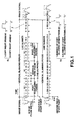
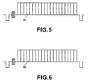
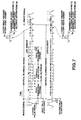
- each field is divided into an effective picture portion which contains useful picture information, such as line intervals 21, 22, etc. in the first field and line intervals 284, 285, etc. in the second field.
- Each field interval also includes a non-picture portion which is shown as the vertical blanking period and includes line intervals 1, 2, ...19, 20 in the first field and line intervals 264, 265, ...282, 283 in the second field.
- the twentieth line in the first field, i.e. line 20 normally is "blank"
- the twentieth line of the second field i.e. line 283, also normally is blank.
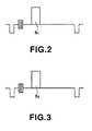
- a copyright information signal S 1 is superposed in line 20 of the first field and a copy generation signal S 2 is superposed in line 283 of the second field. That is, the twentieth line interval in each field has superposed therein the copyright information and copy generation signals S 1 and S 2 , respectively. This is shown in greater detail in Figures 2 and 3.
- the copy generation signal S 2 also is formed as a single bit signal.
- the copy generation signal shown in Figures 1-3 indicates whether one generation or zero generations of the video signal may be made, in other embodiments described below the copy generation signal S 2 is a plural-bit signal indicative of a count identifying the number of generations of copies that may be made of the video signal. However, for simplification, it is assumed herein that the copy generation signal S 2 simply is a single bit signal.
- the copyright information and copy generation signals are recorded in different line intervals in different fields. As will be described, these signals may be recorded in the same line interval in each field or in different line intervals in each field.
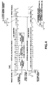
- Figures 4-6 represent an embodiment similar to that shown in Figures 1-3, except that in Figures 4-6 copyright information signal S 1 and copy generation signal S 2 are simply respective ones of several bits representing other data, this data being referred to as vertical blanking interval data (VBID).
- VBID vertical blanking interval data
- the VBID data superposed in line 20 of the first field contains the copyright information signal S 1
- the VBID data superposed in line 283 of the second field contains copy generation signal S 2 .
- S 1 and S 2 are shown simply as single bit signals.
- the copyright information and copy generation signals S 1 and S 2 recorded in lines 20 and 283, respectively may be readily detected simply by sensing the vertical synchronizing pulses and then counting a suitable number of line intervals thereafter, thus detecting the twentieth line interval in each field.
- Those of ordinary skill in the art are sufficiently familiar with suitable detecting arrangements by which the twentieth line interval and, thus, the copyright information and copy generation signals may be detected.
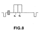
- Figure 7 is similar to Figure 1, except that in the embodiment shown in Figure 7, copyright information signal S 1 and copy generation signal S 2 are recorded in the same line interval. It is seen that the copyright information and copy generation signals are recorded in the twentieth line interval of each field of a frame, namely line 20 of the first field and line 283 of the second field.
- copyright information signal S 1 is illustrated as a single bit and copy generation signal S 2 likewise is illustrated as a single bit.
- Figure 9 is similar to Figure 4, except that in the embodiment shown in Figure 9, the copyright information signal S 1 and the copy generation signal S 2 both are included in the same VBID code contained in the twentieth line interval of each field. Hence, the VBID code containing the copyright information and copy generation signals S 1 and S 2 is disposed in line 20 of the first field and in line 283 of the second field.
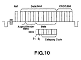
- Figure 10 shows in greater detail the format of the VBID code containing the copyright information and copy generation signals.
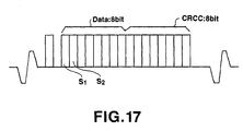
- the VBID code shown in Figure 10 is comprised of a reference bit used, for example, for synchronization purposes, followed by fourteen bits of data and six bits of an error check code (such as cyclical redundancy check code).
- the fourteen data bits represent aspect ratio information (e.g. aspect ratios of 16:9 or 4:3), header information which identifies the type of data that is represented by the next-following data bits, and then 8-bit data.
- the first two bits of this 8-bit data represent copyright information and copy generation data and the remaining six bits may be used to convey other information, such as whether the video picture is a three-dimensional (3D) picture, whether title information is being transmitted, etc.
- the information conveyed by the VBID code, other than the copyright information and copy generation signals are not particularly relevant to the present embodiment; and in the interest of brevity, further description of the VBID code is not provided herein.
- Figures 11 and 12 are other examples of VBID formats and illustrate the versatility of the VBID code and the flexibility thereof, namely that the copyright information and copy generation signals may be included at any desired locations of the VBID code, regardless of the particular format of such code.
- the header information shown in Figure 10 may be omitted, as represented by Figures 11 and 12; and the reference bit shown in Figure 10 likewise may be omitted as represented by Figure 12.
- the VBID code since the VBID code is included in a particular line interval of a field, the VBID code may be readily detected; and the presence therein of the copyright information and copy generation signals may be detected. Consequently, a determination of whether the video signal may be copied is made as a function of the values of S 1 and S 2 , as discussed above.
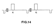
- Figure 13 is similar to Figure 1, except that copyright information signal S 1 and copy generation signal S 2 are included in different line intervals in the same field. More particularly, and as an example, copyright information signal S 1 is located in the nineteenth line interval in each field and copy generation signal S 2 is located in the twentieth line interval in each field. Hence, copyright information and copy generation signals S 1 and S 2 are superposed in lines 19 and 20 of the first field and lines 282 and 283 of the second field. As shown in Figure 14, the copyright information signal S 1 is represented as a single bit signal and, similarly, the copy generation signal S 2 also is represented as a single bit signal. Although the copyright information signal is shown to precede the copy generation signal, it will be readily apparent that, if desired, this sequence may be reversed.
- Figures 15 and 16 represent an embodiment similar to that shown in Figures 13 and 14, except that in Figures 15 and 16 copyright information signal S, and copy generation signal S 2 are included in the VBID data.
- the VBID data which includes copy information signal S 1 is superposed in line 19 of the first field and in line 282 of the second field; and the VBID data containing copy generation signal S 2 is superposed in line 20 of the first field and in line 283 of the second field. It is appreciated that in the embodiments of Figures 13-14 and Figures 15-16, each field of each frame contains both copyright information signal S 1 and copy generation signal S 2 .
- the copyright information and copy generation signals are superposed in specific lines of the respective fields of the video signal.
- lines 19 and 20 of the first field and lines 282 and 283 of the second field are representative of those lines in which these signals are superposed.
- the copyright information and copy generation signals may be superposed in any desired lines in that portion of the video signal which does not contain useful picture information.
- the superposition of the copyright information and copy generation signals in the so-called non-picture portion of the video signal is applicable to various different types of broadcast standards.
- the copyright information and copy generation signals may be superposed in the non-picture portion of an NTSC signal, a phase alternating line PAL signal or a high definition (HD) signal.
- the copyright information and copy generation signals may be superposed in the thirty-second line interval of each field of an HD frame, such as line 32 of the first field and line 595 of the second field.
- Figure 17 schematically illustrates VBID data which contain the copyright information and copy generation signals S 1 and S 2 that may be superposed in the thirty-second line interval of each HD field.
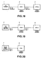
- FIG. 18 Three typical examples of serial copy management that may be achieved by the single bit copyright information and copy generation signals are represented by the block diagrams of Figures 18-20.
- a video signal on which the copyright information and copy generation signals S 1 and S 2 are superposed is received by a television tuner 1. It will be appreciated that this video signal may be broadcasted or may be supplied as video signals reproduced from a video disk or from a video tape.
- the video signal which is supplied by tuner 1 to, for example, a video recorder 2 may be recorded by the video recorder.
- the superposed copyright information and copy generation signals which are recorded with the video signal by video recorder 2 admit of their same states as are present in the video signal supplied to the video recorder.
- video recorder 5 is enabled to record one generation of the video signal but a further generation from the video signal recorded by video recorder 5 cannot be made. That is, the copy made by video recorder 5 cannot be re-copied. Stated otherwise, only one generation of a dubbed video signal may be obtained.
- this video signal is supplied to a recorder, such as video recorder 8, having the copy protection circuitry of the present embodiment, the video recorder is inhibited from recording this video signal. That is, since the superposed copyright information and copy generation signals indicate that no generations of the video signal may be made, even a single generation, or copy, of the video signal is inhibited.
- the video signal which is reproduced by video disk player 7 may, nevertheless, be displayed as an acceptable video picture.
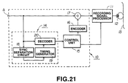
- circuitry which may be included in the recording channel of a video recorder is illustrated in block diagram form. As will be described, this circuitry is adapted to superpose onto the non-picture portion of a video signal the aforementioned copyright information and copy generation signals; and, moreover, is adapted to detect the presence of such signals which may be superposed on a received video signal so as to selectively control the recording operation of the video recorder.
- the illustrated circuitry is comprised of a superposition unit 10 which includes a copy protection detector 14, and also is comprised of a controllable recording signal processor 11.
- a video signal supplied to an input terminal A of the circuitry illustrated in Figure 21 includes the aforementioned copyright information and copy generation signals S 1 and S 2 in the non-picture portion of the video signal.
- S 1 may be superposed in the twentieth line interval of the first field of a video frame and S 2 may be superposed in the twentieth line interval of the second field.
- both S 1 and S 2 may be superposed in the twentieth line interval of each field; and as yet another alternative, S 1 and S 2 may be superposed in the nineteenth and twentieth line intervals of each field.
- the particular line intervals in which S and S are superposed may vary. Nevertheless, such line intervals are predetermined and the presence therein of the copyright information and/or copy generation signals may be readily detected by copy protection detector 14.
- the copy protection detector includes a synchronizing signal separator 18, a timing generator 19 and a decoder 20.
- Synchronizing signal separator 18 and decoder 20 are connected in common to input terminal A to receive the video signal supplied to the input terminal.
- the synchronizing signal separator is adapted to separate the vertical and horizontal synchronizing pulses from the received video signal; and these separated sync pulses are used to trigger timing generator 19.
- the timing generator is adapted to be preset to a predetermined count in response to the separated vertical sync pulses, which count is incremented in response to each separated horizontal sync pulse. In this manner, timing generator 19 functions to count the line intervals in each field.
- the timing generator supplies an enable signal to decoder 20 whereupon the copyright information and copy generation signals then present are decoded. It will be appreciated that the copyright information and copy generation signals S 1 and S 2 are decoded by the decoder even if S 1 and S 2 are included in VBID data, discussed above.
- a control unit 15 is coupled to the output of copy protection detector 14, namely the output of decoder 20, and, depending upon the decoded copyright information and copy generation signals S 1 and S 2 , the control unit selectively controls the operation of recording signal processor 11 and, moreover, supplies updated copyright information and copy generation signals to an encoder 16 for superposition in the non-picture portion of the video signal supplied by input terminal A.
- Encoder 16 is adapted to generate the proper signal waveform of the copyright information and copy generation signals, these signals being supplied to a mixer 17 for superposition on the video signal.
- the encoder is adapted to generate copyright information signal S 1 and copy generation signal S 2 having the signal waveforms shown in Figures 2 and 3, or shown in Figures 5 and 6, or shown in Figure 8, or shown in Figure 10, or shown in Figures 11-12, or shown in Figure 14 or shown in Figures 16 and 17 discussed above.
- magnetic medium 13 comprises a magnetic tape; although it will be appreciated that the magnetic medium may adopt other forms, such as a magnetic disk.
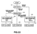
- Control unit 15 may be constructed as a central processing unit (CPU), such as a microprocessor, or the like. The manner in which the control unit operates now will be described in conjunction with the flow chart illustrated in Figure 22.
- CPU central processing unit
- timing generator 19 generates a suitable gating or window pulse to enable decoder 20 to decode copyright information signal S, and copy generation signal S 2 which are superposed in the predetermined line interval(s) of the non-picture portion of the received video signal discussed above. It is further assumed that control unit 15 is supplied with suitable indications of the levels, or bit values, of S 1 and S 2 . Initially, the routine executed by control unit 15 inquires, at 101, if the copyright information signal S 1 is 0 or 1.
- the routine then advances to step 103 which permits recording signal processor 11 to record the video signal with the new copyright information and copy generation signals superposed thereon.
- a video signal recorded on a record medium which includes copy protection information, such as the aforementioned superposed copyright information and copy generation signals S 1 and S 2 , may be reproduced from the record medium and the copy protection information may be re-superposed on the reproduced video signal in the proper, predetermined line intervals.
- An example of circuitry adapted to carry out this operation is illustrated in the block diagram shown in Figure 23.
- the illustrated circuitry comprises a reproducing signal processor 23 and a superposition unit 24, the latter being coupled to the reproducing signal processor and being adapted to superpose onto the non-picture portion of the video signal processed by the reproducing signal processor the copyright information signal S 1 and the copy generation signal S 2 .
- a video signal reproduced by a head 22 from record medium 21 is assumed to include copy protection information.
- the copy protection information consists of the aforementioned copyright information and copy generation signals S 1 and S 2 ; and in another embodiment, the copy protection information consists of a predetermined signal, waveform or code intended to indicate whether the viewable picture which may be displayed from the video signal is subject to copyright and also to indicate whether 1 or 0 generations of copies can be made from the reproduced video signal.
- the reproduced video signal containing this copy protection information is suitably processed by reproducing signal processor 23 (e.g. the video signal is demodulated, equalized, etc.) and supplied to superposition unit 24.
- the superposition unit includes a copy protection detector 25, a control unit 26, an encoder 27 and a mixer 28, the latter being adapted to superpose onto the non-picture portion of the reproduced video signal copyright information and copy generation signals S 1 and S 2 produced by encoder 27.
- Copy protection detector 25 is coupled to the output of reproducing signal processor 23 and is adapted to detect the aforementioned copy protection information included in the reproduced video signal. It is appreciated that this copy protection information may take the form of signals S 1 and S 2 ; or other waveforms or codes may be used, as mentioned above. In the preferred embodiment, the copy protection information is in the form of signals S 1 and S 2 which admit of the states discussed above and shown in Table 1.
- copy protection detector 25 Upon detecting the status of the copyright information and copy generation signals, copy protection detector 25 supplies suitable status indications to control unit 26 which, in turn, controls encoder 27 to supply to mixer 28 updated, or new copyright information and copy generation signals.
- control unit 26 controls encoder 27 to supply to mixer 28 updated, or new copyright information and copy generation signals.
- the copyright information and copy generation signals which are detected by copy protection detector 25 are regenerated and supplied to mixer 28 to be superposed onto the appropriate line intervals of the video signal, discussed above.
- the copy protection information included in the reproduced video signal is other than the signals S 1 and S 2 ; and control unit 26 is responsive to the detected copy protection information to control encoder 27 to supply to mixer 28 copyright information and copy generation signals S 1 and S 2 of appropriate states.
- mixer 28 supplies to an output terminal the reproduced video signal on which the copyright information and copy generation signals S 1 and S 2 are superposed in the non-picture portion thereof.
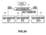
- Control unit 26 may be in the form of a central processor unit (CPU) such as a microprocessor programmed to operate in accordance with the routine illustrated by the flow chart of Figure 24. This routine operates as follows:
- inquiry is made as to whether the copy protection information detected by copy protection detector 25 indicates (a) that the reproduced video signal may be copied without limitation, or (b) that the reproduced video signal may be recorded to provide but a single generation of copies, or (c) that the video signal may not be copied.
- the copy protection information included in the reproduced video signal indicates that only one generation of copies may be made from that video signal.
- These copyright information and copy generation signals are superposed onto the non-picture portion of the reproduced video signal; and the superposed video signal is supplied to the output terminal from mixer 28.
- the copy protection information included in the video signal reproduced from medium 21 indicates that the video signal cannot be copied.
- These copyright information and copy generation signals are superposed onto the non-picture portion of the reproduced video signal and supplied to the output terminal shown in Figure 23. It will be appreciated that if this video signal is received by a video recorder which includes the circuitry shown in Figure 21, the recorder will be inhibited from recording that video signal.
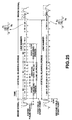
- the copyright information signal S 1 is a single bit signal and copy generation signal S 2 is a 2-bit signal and that both signals S 1 and S 2 are superposed in line 20 of each field.
- S 1 and S 2 are superposed in line 20 of the first field and line 283 of the second field, as illustrated in Figure 25.
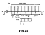
- copyright information and copy generation signals S 1 and S 2 are included in such VBID data, such as illustrated in Figure 26.
- the VBID data is comprised of four separate data fields designated A, B, C and D.
- the A field is comprised of two bits representing identifying data.
- the B field is comprised of four bits representing a mode number.
- the C field is comprised of eight bits representing data or data flags.
- the D field is comprised of six bits representing an error check code such as cyclic redundancy check code.
- the identifying data constitutes discrimination data relating to the picture signal transmission system wherein the first bit represents the aspect ratio of the viewable picture that may be displayed from the video signal (e.g. an aspect ratio of 16:9 or an aspect ratio of 4:3); and the second bit indicates a standard system or a letter box system.
- the first bit represents the aspect ratio of the viewable picture that may be displayed from the video signal (e.g. an aspect ratio of 16:9 or an aspect ratio of 4:3)
- the second bit indicates a standard system or a letter box system.
- the mode number data (the B field) is adapted to classify the data or the flags included in the C field into one of sixteen different types. A summary of these types of data or flags is summarized in Table 3, wherein the expression "TBD” means "to be determined.”
- Mode Number (B) Contents Coding (C) 0000 System Flags (TABLE 4) 0001 Year BCD (00 ⁇ 99) 0010 Month BCD (01 ⁇ 12) 0011 Day BCD (01 ⁇ 31) 0100 Hour BCD (00 ⁇ 29) 0101 Minute BCD (00 ⁇ 59) 0110 TBD 0111 TBD 1000 TBD 1001 TBD 1010 TBD 1011 TBD 1100 Text Start Binary (Text Data Format) 1101 Text Data Binary or ASCII 1110 Text End Binary (Check Sum) 1111 TBD
- mode number [0000] means that the 8-bit data in the C field represents a system flag.
- Mode number [0001] means that the 8-bit data in the C field represents the year in which the video signal was recorded.
- the mode number [1100] indicates the start of a letter string of text data;
- mode number [1101] means that the 8-bit data in the C field represents an alphabetic letter;
- mode number [1110] indicates the end of a letter string (e.g. the letter data represented in the 8-bit C field is the last letter in the string).
- alphabetic data thus permits text information, such as the title of the video program, to be included in the video signal itself.
- the system flags represented by the eight bits of the C field may be summarized as follows: Bit Number Flag Name 1 0 bit 0 Copyright Information S 1 Copyright Present Copyright Absent bit 1 Copy Generation Information S 2 TABLE 5 bit 2 bit 3 3D Info. Yes No bit 4 TBD bit 5 TBD bit 6 TBD bit 7 Title Info. Yes No
- bit 0 of the system flags represents copyright information signal S 1 and bits 1 and 2 of the system flags represent copy generation signal S 2 .
- Bit 3 of the system flags indicates whether the viewable picture which may be displayed from the video signal is a three-dimensional (3-D) picture; and bit 7 of the system flags indicates whether or not the letter box (see Table 2) contains title information. It is appreciated that the representations of bits 4, 5 and 6 of the system flags are to be determined at a future time.
- the three-dimensional information represented by bit 3 of the system flags is used to control a 3-D mode in which a picture is recorded with parallax between the odd and even fields, and switching is effected between the odd and even fields by a liquid crystal shutter during picture reproduction for stereoscopic representation.
- the information represented by bit 7 of the system flags controls the sliding of the title from the black area of the video picture so as to be displayed in another area and to prevent zooming which may result in extinguishing the title if a wide aspect ratio picture is to be displayed and the title is disposed in the black area of the letter box.
- the copy generation signal S is represented by two bits, it is appreciated that up to three successive generations of copies can be made from the video signal in which this copy generation signal is superposed, depending upon the values of the S 2 bits. For example, if the copyright information signal S 1 is 1, then the number of possible generations of copies that can be made from the video signal are as summarized below in Table 5: Bit 1 Bit 2 Number of Possible Copy Generations 1 1 3 Generations 1 0 2 Generations 0 1 1 Generation 0 0 None
- Table 6 provides a summary of the copy control which may be effected by the single bit copyright information signal S 1 and the 2-bit copy generation signal S 2 : Copyright Info.
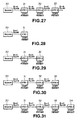
- Copy control as a function of the copyright information and copy generation signals S 1 and S 2 summarized in Table 6 are schematically depicted by the block diagrams shown in Figures 27-31.
- a source 30 of video signals e.g. a video disk, a prerecorded video tape, a broadcast transmission, or the like
- this video signal may be recorded by a video recorder 31 without any change or modification in the copy generation signal S 2 .
- the video signal recorded by video recorder 31 subsequently may be reproduced and re-recorded as a second generation copy by a video recorder 32.
- Figure 27 is applicable regardless of the number of successive generations of copies that is represented by the copy generation signal S 2 .
- This information is detected by a control unit included in video recorder 31 (e.g. control unit 15 of Figure 21) which is inhibited by S 1 and S 2 from recording the video signal.
- the control unit included in recorder 31 detects S 1 and S 2 and permits the video signal to be recorded.
- this reproduced video signal cannot be re-recorded by, for example, recorder 32.
- only one copy of the video signal supplied by source 30 may be recorded, as represented by Figure 29.
- each video recorder includes the circuitry shown in Figure 21 in the recording channel thereof and also the circuitry shown in Figure 23 in the reproducing channel thereof.
- the circuitry included in the recording channel operates to decrement the count represented by the copy generation signal S 2 .
Description
- This invention relates to copy protection of a video signal.
- Various techniques and formats have been proposed to prevent video signals from being copied, or dubbed, without authorization. For example, it is preferable in many environments to permit a video signal to be displayed as a video picture on, for example, a television monitor, but to prevent that same video signal from being recorded by a video recorder. The video signal may be transmitted via cable, direct satellite broadcast (DSB) or over-the-air; or the video signal may be recorded on a video tape or a video disk. In the field of sales or rentals of video tapes and video disks, substantial amounts of revenues will be lost if a user is permitted to make a copy of the video program on a video tape or disk, thereby depriving the originator or distributor of the video tape or video disk of additional sales or rentals. Even though the unlawful re-recording or dubbing of such video programs may constitute copyright infringement, the threat of prosecution therefor presents little if any deterrent to such unlawful copying. Consequently, more positive approaches have been adopted to prevent a user from making an unauthorized copy of a video program in the form of a video recording thereof.
- In one anti-copying scheme the video signal is modified to defeat the satisfactory operation of a typical video recorder yet still permit the display of an acceptable video picture therefrom. This is achieved by reducing the number of vertical synchronizing pulses included in the vertical blanking interval, thereby defeating the servo locking operation of the typical video recorder but permitting adequate detection of the vertical synchronizing pulses in the usual television receiver sync detector. In another proposal high amplitude pulses are inserted into a normally blank line interval of the vertical blanking interval so as to cause the usual automatic gain control (AGC) circuitry in a typical video recorder to reduce the recording level of the signal recorded thereby, resulting in a recorded video signal whose amplitude is effectively zero.
- As yet another example, it has been proposed to superpose a copy inhibit pulse on, for example, the equalizing or vertical synchronizing pulses normally included in the vertical blanking interval and to include in the recording channel of a video recorder a detector which operates to inhibit the recorder from operating in a record mode upon detecting this inhibit pulse.
- WO-A-9 216 944 discloses a digital recording system for image and audio signals. As part of the recording process, copyright information is inserted into the recording signal. The copyright information includes a copyright fleg and a copy counter, the value of which is raised by one of each copy process.
- While there is merit to each of the foregoing proposals, none of them addresses the problem of permitting one copy of the video signal from being made but prohibiting the copy from being copied further. In many situations it may be desirable to permit a consumer to make one copy directly from a video signal (whether that video signal is broadcast or reproduced from a video tape or video disk) but the number of successive generations of copies is to be controlled. For example, a first generation may be permitted but a second generation may be prohibited. As another example, first and second generations may be permitted but a third generation may not (i.e. a recording and a re-recording may be permitted but a re-re-recording may be prohibited). In the foregoing copy protection schemes, if a video signal is permitted to be copied, a copy of the copied signal may be made and successive generations likewise may be made. But if a video signal is prohibited from being copied, even a single generation copy cannot be made. That is, prior proposals have not considered what is referred to herein as a serial copy management system (SCMS).
- Respective aspects of the invention are set forth in
claims - In accordance with this invention, a video signal is processed to selectively permit copying thereof by superposing on that portion of the video signal which does not contain useful picture information a copyright information signal indicative of whether the viewable picture that is produced from the video signal is subject to copyright and a copy generation signal indicative of the number of successive generations of copies that can be made from the video signal.
- In one embodiment, the copyright information and copy generation signals are superposed in respectively different line intervals of the video signal. In another embodiment, the copyright information and copy generation signals are superposed in the same line interval. In a further embodiment, the copyright information signal is superposed in a line interval of one field of a video frame and the copy generation signal is superposed in a line interval of the other field of that frame. In a still further embodiment, the copyright information and copy generation signals are superposed in different line intervals in the same field. Preferably, the copyright information and copy generation signals are superposed in the vertical blanking interval of the video signal.
- Preferably, the video signal having the copyright information and copy generation signals superposed thereon is recorded on a record medium.
- Preferably, a video recorder that is supplied with the video signal having the copyright information and copy generation signals superposed thereon is selectively inhibited depending upon the information conveyed by the superposed signals. In one embodiment, if re-recording of the video signal is permitted, the copy information signal that is recorded with the video signal is modified to indicate a decremented number of successive generations of copies that can be made from the recorded video signal. For example, the copy generation signal may be a plural-bit signal indicative of a count, and this count is decremented when the video signal is recorded (or dubbed). Consequently, the number of successive re-recordings may be regulated.
- Preferably, a video signal reproducing channel is provided with a detector for detecting copy protection information that is contained in the reproduced video signal, thereby superposing on that portion of the video signal which does not contain useful picture information the aforementioned copyright information and copy generation signals. Hence, re-recording of the reproduced video signal and successive generations of re-recordings are selectively enabled/inhibited.
- Preferably, and notwithstanding the superposed copyright information and copy generation signals, the video signal nevertheless may be readily displayed.
- At least preferred embodiments of the invention provide a technique for superposing on that portion of the video signal which does not contain useful picture information copy protection information which includes information representing the number of successive generations of copies that can be made from the video signal.
- Accordingly, at least preferred embodiments of the invention provide an improved technique for controlling the copying of a video signal; video signal copy control by which the number of successive generations of copies that can be made from an input video signal is regulated; a serial copy management system for a video signal, thereby permitting, for example, a copy of an input video signal to be made but a copy of the copy (that is a re-recording of the copy) to be prohibited; recording circuitry that detects the aforementioned copyright information and copy generation signals to selectively enable or inhibit recording of the video signal; a copy generation signal detector which selectively decrements the number of successive generations of copies indicated by the copy generation signal; and circuitry included in the playback channel of a video recorder which detects copy protection information contained in the reproduced video signal and which superposes on the reproduced video signal a copyright information signal and a copy generation signal so as to selectively control re-recording of the reproduced video signal.
- The invention will now be described by way of example with reference to the accompanying drawings, throughout which like parts are referred to by like references, and in which:
- Figure 1 is a waveform diagram of relevant portions of two fields of a frame of a National Television Standards Committee (NTSC) video signal containing copyright information and copy generation signals;
- Figures 2 and 3 are waveform diagrams illustrating the superposed copyright information and copy generation signals, respectively;
- Figure 4 is a waveform diagram illustrating the superposition of copyright information and copy generation signals as part of identifying data included in a vertical blanking interval (VBID);
- Figures 5 and 6 are waveform diagrams of the VBID signals shown in greater detail;
- Figure 7 is a waveform diagram of two fields of an NTSC signal wherein the copyright information and copy generation signals are recorded in the same line interval in each field;
- Figure 8 is a waveform diagram illustrating in greater detail the recording in the same line interval of the copyright information and copy generation signals;
- Figure 9 is a waveform diagram illustrating the incorporation of the copyright information and copy generation signals in VBID data in each field;
- Figure 10 is a waveform diagram showing in greater detail the copyright information and copy generation signals as part of the VBID data;
- Figures 11 and 12 are waveform diagrams of modifications of the waveform diagram shown in Figure 10;
- Figure 13 is a waveform diagram of two fields of a video signal in which the copyright information and copy generation signals are recorded in different line intervals in each field;
- Figure 14 is a waveform diagram showing in greater detail the recording in different line intervals of the copyright information and copy generation signals;
- Figure 15 is a waveform diagram of two fields of a video signal in which the copyright information and copy generation signals are included in VBID data disposed in two line intervals of each field;
- Figure 16 is a waveform diagram showing in greater detail the VBID data in the two line intervals and including the copyright information and copy generation signals;
- Figure 17 is a waveform diagram of VBID data that may be used in high definition television signals and which includes the copyright information and copy generation signals;
- Figures 18-20 are block diagrams which are useful in understanding the manner in which the embodiment effects copy protection;
- Figure 21 is a block diagram of circuitry which may be included in the recording channel of a video recorder;
- Figure 22 is a flow chart representing the routine carried out
by
control unit 15 of Figure 21; - Figure 23 is a block diagram of circuitry which may be provided in a video signal reproducing channel;
- Figure 24 is a flow chart of the routine carried out by
control unit 26 of Figure 23; - Figure 25 is a waveform diagram of two fields of a video signal which contain a copyright information signal and a plural-bit copy generation signal;
- Figure 26 is a waveform diagram showing in greater detail VBID data containing the copyright information signal and plural-bit copy generation signal; and
- Figures 27-31 are block diagrams which are useful in understanding the manner in which copying is selectively controlled.
-
- Referring to Figure 1, there is illustrated a portion of each of two fields of a frame of video signals in accordance with the NTSC standard. It is appreciated that each field is divided into an effective picture portion which contains useful picture information, such as
line intervals line intervals 284, 285, etc. in the second field. Each field interval also includes a non-picture portion which is shown as the vertical blanking period and includesline intervals line intervals line 20, normally is "blank" and the twentieth line of the second field, i.e.line 283, also normally is blank. In the embodiment illustrated in Figure 1, a copyright information signal S1 is superposed inline 20 of the first field and a copy generation signal S2 is superposed inline 283 of the second field. That is, the twentieth line interval in each field has superposed therein the copyright information and copy generation signals S1 and S2, respectively. This is shown in greater detail in Figures 2 and 3. - In accordance with one embodiment, the copyright information signal S1 is a single bit and when the viewable picture which is reproduced from the video signal is subject to copyright, S1 = 1. If the viewable picture is not subject to copyright, S1 = 0.
- In the embodiment described herein, the copy generation signal S2 also is formed as a single bit signal. When S2 = 0, a single generation of the video signal may be recorded; but when S2 = 1, no generations of the video signal may be made. More particularly, the video signal cannot be recorded if S1 = 1 and S2 = 1. Although the copy generation signal shown in Figures 1-3 indicates whether one generation or zero generations of the video signal may be made, in other embodiments described below the copy generation signal S2 is a plural-bit signal indicative of a count identifying the number of generations of copies that may be made of the video signal. However, for simplification, it is assumed herein that the copy generation signal S2 simply is a single bit signal.
- As can be seen from Figures 1-3, the copyright information and copy generation signals are recorded in different line intervals in different fields. As will be described, these signals may be recorded in the same line interval in each field or in different line intervals in each field.
- Figures 4-6 represent an embodiment similar to that shown in Figures 1-3, except that in Figures 4-6 copyright information signal S1 and copy generation signal S2 are simply respective ones of several bits representing other data, this data being referred to as vertical blanking interval data (VBID). Here, the VBID data superposed in
line 20 of the first field contains the copyright information signal S1 and the VBID data superposed inline 283 of the second field contains copy generation signal S2. As before, S1 and S2 are shown simply as single bit signals. - It will be appreciated that the copyright information and copy generation signals S1 and S2 recorded in
lines - Figure 7 is similar to Figure 1, except that in the embodiment shown in Figure 7, copyright information signal S1 and copy generation signal S2 are recorded in the same line interval. It is seen that the copyright information and copy generation signals are recorded in the twentieth line interval of each field of a frame, namely
line 20 of the first field andline 283 of the second field. As shown in Figure 8, copyright information signal S1 is illustrated as a single bit and copy generation signal S2 likewise is illustrated as a single bit. As before, S1 = 1 indicates that the picture reproduced from the video signal is subject to copyright; S2 = 0 indicates that at least one generation of copies may be made of the video signal and S2 = 1 indicates that no generations of copies may be made from the video signal. Hence, in the example being described, the video signal cannot be recorded when S1 = 1 and S2 = 1. - Figure 9 is similar to Figure 4, except that in the embodiment shown in Figure 9, the copyright information signal S1 and the copy generation signal S2 both are included in the same VBID code contained in the twentieth line interval of each field. Hence, the VBID code containing the copyright information and copy generation signals S1 and S2 is disposed in
line 20 of the first field and inline 283 of the second field. Figure 10 shows in greater detail the format of the VBID code containing the copyright information and copy generation signals. - It will be seen that the VBID code shown in Figure 10 is comprised of a reference bit used, for example, for synchronization purposes, followed by fourteen bits of data and six bits of an error check code (such as cyclical redundancy check code). The fourteen data bits represent aspect ratio information (e.g. aspect ratios of 16:9 or 4:3), header information which identifies the type of data that is represented by the next-following data bits, and then 8-bit data. It is seen that the first two bits of this 8-bit data represent copyright information and copy generation data and the remaining six bits may be used to convey other information, such as whether the video picture is a three-dimensional (3D) picture, whether title information is being transmitted, etc. The information conveyed by the VBID code, other than the copyright information and copy generation signals are not particularly relevant to the present embodiment; and in the interest of brevity, further description of the VBID code is not provided herein.
- Figures 11 and 12 are other examples of VBID formats and illustrate the versatility of the VBID code and the flexibility thereof, namely that the copyright information and copy generation signals may be included at any desired locations of the VBID code, regardless of the particular format of such code. For example, the header information shown in Figure 10 may be omitted, as represented by Figures 11 and 12; and the reference bit shown in Figure 10 likewise may be omitted as represented by Figure 12. Nevertheless, since the VBID code is included in a particular line interval of a field, the VBID code may be readily detected; and the presence therein of the copyright information and copy generation signals may be detected. Consequently, a determination of whether the video signal may be copied is made as a function of the values of S1 and S2, as discussed above.
- Figure 13 is similar to Figure 1, except that copyright information signal S1 and copy generation signal S2 are included in different line intervals in the same field. More particularly, and as an example, copyright information signal S1 is located in the nineteenth line interval in each field and copy generation signal S2 is located in the twentieth line interval in each field. Hence, copyright information and copy generation signals S1 and S2 are superposed in
lines lines - Figures 15 and 16 represent an embodiment similar to that shown in Figures 13 and 14, except that in Figures 15 and 16 copyright information signal S, and copy generation signal S2 are included in the VBID data. In the illustrated embodiment, the VBID data which includes copy information signal S1 is superposed in
line 19 of the first field and inline 282 of the second field; and the VBID data containing copy generation signal S2 is superposed inline 20 of the first field and inline 283 of the second field. It is appreciated that in the embodiments of Figures 13-14 and Figures 15-16, each field of each frame contains both copyright information signal S1 and copy generation signal S2. - In the examples discussed above, the copyright information and copy generation signals are superposed in specific lines of the respective fields of the video signal. In particular,
lines lines line 32 of the first field and line 595 of the second field. Figure 17 schematically illustrates VBID data which contain the copyright information and copy generation signals S1 and S2 that may be superposed in the thirty-second line interval of each HD field. - The examples discussed above have described the copyright information and copy generation signals as respective single bit signals. The following table summarizes the conditions, or states, of these signals and indicates whether the video signal in which such copyright information and copy generation signals are superposed may be recorded, or dubbed. It will be appreciated that the expression "copy permitted" indicates that at least one generation of the video signal may be recorded; and the expression "copy inhibited" indicates that no generations of the video signal may be recorded:
Copyright Info. S1 Copy Generation S2 Recordable Generations 0 0 Copy Permitted 0 1 Copy Permitted 1 0 Copy Permitted 1 1 Copy Inhibited - In the foregoing Table, S1 = 1 indicates that the video picture that may be displayed from the video signal is subject to copyright and S1 = 0 indicates that the video picture is not subject to copyright. In addition, S2 = 0 indicates that at least one generation of the video signal may be recorded; and S2 = 1 indicates that no generations of the video signal may be recorded. Hence, a video signal on which is superposed copyright information and copy generation signals S1 = 1 and S2 = 1 is inhibited from being recorded.
- Three typical examples of serial copy management that may be achieved by the single bit copyright information and copy generation signals are represented by the block diagrams of Figures 18-20. In Figure 18, it is assumed that a video signal on which the copyright information and copy generation signals S1 and S2 are superposed is received by a
television tuner 1. It will be appreciated that this video signal may be broadcasted or may be supplied as video signals reproduced from a video disk or from a video tape. In any event, in the example represented by Figure 18, it is assumed that the video signal is not subject to copyright and, therefore, S1 = 0. Consequently, and with reference to copy protection, it is of no moment if copy generation signal S2 = 0 or S2 = 1. That is, the video signal which is supplied bytuner 1 to, for example, avideo recorder 2 may be recorded by the video recorder. As represented, the superposed copyright information and copy generation signals which are recorded with the video signal byvideo recorder 2 admit of their same states as are present in the video signal supplied to the video recorder. Hence, the copyright information and copy generation signals S1 and S2 which are superposed on the video signal recorded byvideo recorder 2 and which subsequently are reproduced by the video recorder are represented as S1 = 0 and S2 = 0 or 1. - When the video signal having the superposed copyright information and copy generation signals is reproduced from
video recorder 2 and supplied for re-recording byvideo recorder 3, this re-recording is permitted because the reproduced, superposed copyright information signal S1 = 0. As before, if S1 = 0, it does not matter if S2 = 0 or S2 = 1. Thus,video recorder 3 is permitted to record the video signal reproduced fromvideo recorder 2 on which the illustrated copyright information and copy generation signals are superposed. Thus, a first generation of the video signal may be recorded byvideo recorder 2 and a second generation of the video signal may be recorded byvideo recorder 3. That is, a copy of the original video signal may be made byvideo recorder 2 and a copy of the copy may be made byvideo recorder 3. If desired, further generations of copies of the video signal may be made simply by re-recording the video signal reproduced fromvideo recorder 3 and then re-recording that video signal, and so on. - Figure 19 illustrates the condition that the copyright information signal S1 superposed on the video signal provided by
tuner 4 indicates that the viewable picture that may be produced from this video signal is subject to copyright. Hence, S1 = 1. It is further assumed that the superposed copy generation signal S2 indicates that one generation of the video signal may be recorded. Hence, S2 = 0. As before, the video signal which is supplied to and recovered bytuner 4 may be broadcast thereto or may be supplied from a video disk or a video tape. - In accordance with one embodiment, to be described below, recording circuitry is included in
video recorder 5 to detect the state, or condition, of the superposed copyright information signal S1, and if S1 = 1, the number of generations of copies that are indicated by copy generation signal S2 is decremented. In the present case, since the copy generation signal is a single bit signal and, thus, may indicate 1 or 0 successive generations of copies that can be made from the video signal, the circuitry included in the video recorder is adapted to change over the copy generation signal from S2 = 0 to S2 = 1. Nevertheless, since the superposed copy generation signal supplied tovideo recorder 5 is S2 = 0, the video recorder is permitted to record the video signal having the superposed copyright information and copy generation signals. But, in this embodiment, the superposed copy generation signal S2 which is recorded with the video signal byvideo recorder 5 is changed over to S2 = 1. - Consequently, when the video signal that had been recorded by
video recorder 5 is reproduced, the superposed copy generation signal is S2 = 1; and since the superposed copyright information signal S1 = 1, the reproduced video signal is inhibited from being re-recorded. Accordingly, if the video signal reproduced fromvideo recorder 5 is supplied to another video recorder, such asvideo recorder 6 having copy protection circuitry incorporated therein (such as that shown in Figure 21), S1 = 1 and S2 = 1 inhibitsvideo recorder 6 from recording this video signal. It will be seen, therefore, that when the video signal that is supplied tovideo recorder 5 includes superposed copyright information and copy generation signals S1 = 1 and
S2 = 0, only one generation of the video signal may be recorded and a successive generation may not. Thus, and as has been described above,video recorder 5 is enabled to record one generation of the video signal but a further generation from the video signal recorded byvideo recorder 5 cannot be made. That is, the copy made byvideo recorder 5 cannot be re-copied. Stated otherwise, only one generation of a dubbed video signal may be obtained. - As another example, Figure 20 schematically illustrates the reproduction of a video signal from, for example, a
video disk player 7, wherein the reproduced video signal has superposed thereon copyright information and copy generation signals S1 = 1 and S2 = 1. If this video signal is supplied to a recorder, such asvideo recorder 8, having the copy protection circuitry of the present embodiment, the video recorder is inhibited from recording this video signal. That is, since the superposed copyright information and copy generation signals indicate that no generations of the video signal may be made, even a single generation, or copy, of the video signal is inhibited. Of course, the video signal which is reproduced byvideo disk player 7 may, nevertheless, be displayed as an acceptable video picture. - It will be appreciated that although a video disk player is illustrated in Figure 20, the superposed copyright information and copy generation signals S1 = 1 and S2 = 1 may be included in a video signal that is recorded on a video tape or that is broadcast over-the-air, by cable distribution, by direct satellite broadcast, or the like. Nevertheless, if S1 = 1 and S2 = 1, the video signal upon which these copyright information and copy generation signals are superposed cannot be recorded.
- Turning now to Figure 21, circuitry which may be included in the recording channel of a video recorder is illustrated in block diagram form. As will be described, this circuitry is adapted to superpose onto the non-picture portion of a video signal the aforementioned copyright information and copy generation signals; and, moreover, is adapted to detect the presence of such signals which may be superposed on a received video signal so as to selectively control the recording operation of the video recorder. The illustrated circuitry is comprised of a
superposition unit 10 which includes acopy protection detector 14, and also is comprised of a controllablerecording signal processor 11. Let it be assumed that a video signal supplied to an input terminal A of the circuitry illustrated in Figure 21 includes the aforementioned copyright information and copy generation signals S1 and S2 in the non-picture portion of the video signal. In the examples discussed above, S1 may be superposed in the twentieth line interval of the first field of a video frame and S2 may be superposed in the twentieth line interval of the second field. Alternatively, both S1 and S2 may be superposed in the twentieth line interval of each field; and as yet another alternative, S1 and S2 may be superposed in the nineteenth and twentieth line intervals of each field. Of course, and depending upon the format of the video signal (e.g. NTSC, PAL, HD, etc.), the particular line intervals in which S and S are superposed may vary. Nevertheless, such line intervals are predetermined and the presence therein of the copyright information and/or copy generation signals may be readily detected bycopy protection detector 14. - The copy protection detector includes a synchronizing
signal separator 18, atiming generator 19 and adecoder 20. Synchronizingsignal separator 18 anddecoder 20 are connected in common to input terminal A to receive the video signal supplied to the input terminal. The synchronizing signal separator is adapted to separate the vertical and horizontal synchronizing pulses from the received video signal; and these separated sync pulses are used to triggertiming generator 19. As an example, the timing generator is adapted to be preset to a predetermined count in response to the separated vertical sync pulses, which count is incremented in response to each separated horizontal sync pulse. In this manner,timing generator 19 functions to count the line intervals in each field. When the line interval(s) in which the copyright information and copy generation signals are superposed are reached, the timing generator supplies an enable signal to decoder 20 whereupon the copyright information and copy generation signals then present are decoded. It will be appreciated that the copyright information and copy generation signals S1 and S2 are decoded by the decoder even if S1 and S2 are included in VBID data, discussed above. - A
control unit 15 is coupled to the output ofcopy protection detector 14, namely the output ofdecoder 20, and, depending upon the decoded copyright information and copy generation signals S1 and S2, the control unit selectively controls the operation ofrecording signal processor 11 and, moreover, supplies updated copyright information and copy generation signals to anencoder 16 for superposition in the non-picture portion of the video signal supplied by inputterminal A. Encoder 16 is adapted to generate the proper signal waveform of the copyright information and copy generation signals, these signals being supplied to amixer 17 for superposition on the video signal. For example, the encoder is adapted to generate copyright information signal S1 and copy generation signal S2 having the signal waveforms shown in Figures 2 and 3, or shown in Figures 5 and 6, or shown in Figure 8, or shown in Figure 10, or shown in Figures 11-12, or shown in Figure 14 or shown in Figures 16 and 17 discussed above. -
Recording signal processor 11 may be conventional; and the operation of the recording signal processor may be inhibited bycontrol unit 15 if S1 = 1 and S2 = 1, as discussed above. Assuming that the recording signal processor is not inhibited, it supplies to a recording head 12 a suitably modulated video signal having superposed in the non-picture portion thereof the copyright information and copy generation signals produced byencoder 16 for recording onmagnetic medium 13. In the present example,magnetic medium 13 comprises a magnetic tape; although it will be appreciated that the magnetic medium may adopt other forms, such as a magnetic disk. -
Control unit 15 may be constructed as a central processing unit (CPU), such as a microprocessor, or the like. The manner in which the control unit operates now will be described in conjunction with the flow chart illustrated in Figure 22. - It is assumed that
timing generator 19 generates a suitable gating or window pulse to enabledecoder 20 to decode copyright information signal S, and copy generation signal S2 which are superposed in the predetermined line interval(s) of the non-picture portion of the received video signal discussed above. It is further assumed thatcontrol unit 15 is supplied with suitable indications of the levels, or bit values, of S1 and S2. Initially, the routine executed bycontrol unit 15 inquires, at 101, if the copyright information signal S1 is 0 or 1. Ifinquiry 101 indicates that S1 = 0, that is, the viewable picture which may be displayed from the received video signal is not subject to copyright, the routine advances toinstruction 102 to controlencoder 16 to supply tomixer 17 the copyright information signal S1 = 0 and the copy generation signal S2 = 0 or 1, depending upon the state of S2 as decoded bydecoder 20. That is,encoder 16 is controlled bycontrol unit 15 to make no changes in the copyright information and copy generation signals as received at input terminal A. The routine then advances to step 103 which permitsrecording signal processor 11 to record the video signal with the new copyright information and copy generation signals superposed thereon. - If
inquiry 101 is answered such that S1 = 1, the routine advances toinquiry 104 to determine the state of the copy generation signal S2. Assuming that S2 = 1, thereby indicating that no successive generations of copies can be made from the video signal supplied by input terminal A,control unit 15 inhibitsrecording signal processor 11 from recording the video signal, as represented byinstruction 105. However, ifinquiry 104 indicates that S2 = 0, thus representing that one generation of copies may be made from the input video signal, the routine advances toinstruction 106 which modifies the state of the copy generation signal from S2 = 0 to S2 =1. Additionally, the copyright information signal S, is regenerated as S1 = 1.Mixer 17 superposes the new copyright information and copy generation signals S1 = 1 and S2 = 1 onto the non-picture portion of the video signal supplied by input terminal A, and the resultant, or processed, video signal is recorded onmagnetic medium 13, as represented byinstruction 107. It will be appreciated, however, that when the video signal having the superposed copy protection information S1 = 1 and S2 = 1 subsequently is reproduced frommagnetic medium 13, the reproduced video signal, if supplied to circuitry of the type shown in Figure 21, will not be re-recorded. That is, a second generation of the copy which was made in accordance withinstruction 107 is inhibited. - It will be seen that the flow charts shown in Figure 22 may be summarized by Table 1, discussed above. It is recognized that if copyright information signal S1 is 1, the copy generation signal S2 is decremented. However, if S1 =1 and S2 = 1, there is no need to decrement the copy generation signal because recording of the video signal (having S1 and S2 superposed thereon) is inhibited.
- As another embodiment, a video signal recorded on a record medium which includes copy protection information, such as the aforementioned superposed copyright information and copy generation signals S1 and S2, may be reproduced from the record medium and the copy protection information may be re-superposed on the reproduced video signal in the proper, predetermined line intervals. An example of circuitry adapted to carry out this operation is illustrated in the block diagram shown in Figure 23. The illustrated circuitry comprises a reproducing
signal processor 23 and asuperposition unit 24, the latter being coupled to the reproducing signal processor and being adapted to superpose onto the non-picture portion of the video signal processed by the reproducing signal processor the copyright information signal S1 and the copy generation signal S2. A video signal reproduced by ahead 22 fromrecord medium 21 is assumed to include copy protection information. In one embodiment, the copy protection information consists of the aforementioned copyright information and copy generation signals S1 and S2; and in another embodiment, the copy protection information consists of a predetermined signal, waveform or code intended to indicate whether the viewable picture which may be displayed from the video signal is subject to copyright and also to indicate whether 1 or 0 generations of copies can be made from the reproduced video signal. The reproduced video signal containing this copy protection information is suitably processed by reproducing signal processor 23 (e.g. the video signal is demodulated, equalized, etc.) and supplied tosuperposition unit 24. - The superposition unit includes a
copy protection detector 25, acontrol unit 26, anencoder 27 and amixer 28, the latter being adapted to superpose onto the non-picture portion of the reproduced video signal copyright information and copy generation signals S1 and S2 produced byencoder 27.Copy protection detector 25 is coupled to the output of reproducingsignal processor 23 and is adapted to detect the aforementioned copy protection information included in the reproduced video signal. It is appreciated that this copy protection information may take the form of signals S1 and S2; or other waveforms or codes may be used, as mentioned above. In the preferred embodiment, the copy protection information is in the form of signals S1 and S2 which admit of the states discussed above and shown in Table 1. - Upon detecting the status of the copyright information and copy generation signals,
copy protection detector 25 supplies suitable status indications to controlunit 26 which, in turn, controlsencoder 27 to supply tomixer 28 updated, or new copyright information and copy generation signals. In one embodiment, the copyright information and copy generation signals which are detected bycopy protection detector 25 are regenerated and supplied tomixer 28 to be superposed onto the appropriate line intervals of the video signal, discussed above. In another embodiment, the copy protection information included in the reproduced video signal is other than the signals S1 and S2; andcontrol unit 26 is responsive to the detected copy protection information to controlencoder 27 to supply tomixer 28 copyright information and copy generation signals S1 and S2 of appropriate states. For example, if the copy protection information indicates that the viewable picture which may be displayed from the reproduced video signal is not subject to copyright,control unit 26 controls encoder 27 to supply the copyright information signal S1 = 0. However, if the copy protection information indicates that the viewable picture which may be displayed from the reproduced video signal is subject to copyright information,encoder 27 is controlled to supply tomixer 28 the copyright information signal S1 = 1. Similarly, if the copy protection information included in the reproduced video signal indicates that the video signal is not to be copied,control unit 26 controls encoder 27 to supply tomixer 28 the copy generation signal S2 = 1. - As a result,
mixer 28 supplies to an output terminal the reproduced video signal on which the copyright information and copy generation signals S1 and S2 are superposed in the non-picture portion thereof. -
Control unit 26 may be in the form of a central processor unit (CPU) such as a microprocessor programmed to operate in accordance with the routine illustrated by the flow chart of Figure 24. This routine operates as follows: - Initially, inquiry is made as to whether the copy protection information detected by
copy protection detector 25 indicates (a) that the reproduced video signal may be copied without limitation, or (b) that the reproduced video signal may be recorded to provide but a single generation of copies, or (c) that the video signal may not be copied. This inquiry is determined by examining the copyright information and copy generation signals S1 and S2. Let it be assumed that S1 = 0, meaning that the reproduced video signal may be copied without limitation. As a result,control unit 26 advances toinstruction 112 so as to controlencoder 27 to supply tomixer 28 the signals S1 = and S2 = or 1, depending upon whether the copy generation signal S2 that had been superposed in the video signal recorded onmedium 21 is a 0 or 1. As a result ofinstruction 112, the video signal supplied to the output terminal shown in Figure 23 has superposed on the non-picture portion thereof the copyright information and copy generation signals S1 = and S2 = 0 or 1. - As another example, let it be assumed that the copy protection information included in the reproduced video signal indicates that only one generation of copies may be made from that video signal. As a result, inquiry 111 indicates that S1 = 1 and S2 = 0. That is,
control unit 26 indicates that the viewable picture which may be displayed from the reproduced video signal is subject to copyright (S1 = 1) and only one generation of copies may be made therefrom (S2 = 0). As a result, the routine advances toinstruction 113, wherebyencoder 27 is controlled to supply tomixer 28 the copyright information and copy generation signals S1 = 1 and S2 = 0. These copyright information and copy generation signals are superposed onto the non-picture portion of the reproduced video signal; and the superposed video signal is supplied to the output terminal frommixer 28. - As yet another example, let it be assumed that the copy protection information included in the video signal reproduced from
medium 21 indicates that the video signal cannot be copied. For example, let it be assumed that the reproduced video signal contains superposed copyright information and copy generation signals S1 = 1 and S2 = 1. Hence, inquiry 111 is answered such that the routine advances toinstruction 114, wherebyencoder 27 is controlled to supply tomixer 28 the copyright information and copy protection signals S1 = 1 and S = 1. These copyright information and copy generation signals are superposed onto the non-picture portion of the reproduced video signal and supplied to the output terminal shown in Figure 23. It will be appreciated that if this video signal is received by a video recorder which includes the circuitry shown in Figure 21, the recorder will be inhibited from recording that video signal. - In the examples discussed above, it is assumed that copy generation signal S2 is comprised of a single bit signal. It is further assumed that when S2 = 0, one generation of copies may be made from the video signal and when S2 = 1, zero generations of copies may be made. It is contemplated, however, that copy generation signal S2 may be a plural-bit signal capable of representing a count which is indicative of the number of successive generations or copies that can be made from the video signal. For example, if copy generation signal S2 is a 2-bit signal, then up to three generations of copies may be indicated. If S2 is a 3-bit signal, then up to seven generations of copies may be indicated. For convenience, and in order to simplify the following discussion, it is assumed that S2 is a 2-bit signal.
- As one example, let it be assumed that the copyright information signal S1 is a single bit signal and copy generation signal S2 is a 2-bit signal and that both signals S1 and S2 are superposed in
line 20 of each field. For example, in the NTSC format, S1 and S2 are superposed inline 20 of the first field andline 283 of the second field, as illustrated in Figure 25. Alternatively, if VBID data is included in the non-picture portion of each field, for example, if VBID data is included in the twentieth line interval of each field, then copyright information and copy generation signals S1 and S2 are included in such VBID data, such as illustrated in Figure 26. - Although a complete and full understanding of the VBID data and the various types of information represented thereby is not necessary to an adequate understanding of the present embodiment, a brief description of the VBID data now follows. As shown in Figure 26, the VBID data is comprised of four separate data fields designated A, B, C and D. The A field is comprised of two bits representing identifying data. The B field is comprised of four bits representing a mode number. The C field is comprised of eight bits representing data or data flags. The D field is comprised of six bits representing an error check code such as cyclic redundancy check code.
- More particularly, the identifying data (the A field) constitutes discrimination data relating to the picture signal transmission system wherein the first bit represents the aspect ratio of the viewable picture that may be displayed from the video signal (e.g. an aspect ratio of 16:9 or an aspect ratio of 4:3); and the second bit indicates a standard system or a letter box system. The foregoing may be summarized by Table 2 as follows:
Bit Number 1 0 Contents bit 1 16:9 4:3 Transmission Aspect Ratio bit 2 Letter Box Standard Picture Display Format - The mode number data (the B field) is adapted to classify the data or the flags included in the C field into one of sixteen different types. A summary of these types of data or flags is summarized in Table 3, wherein the expression "TBD" means "to be determined."
Mode Number (B) Contents Coding (C) 0000 System Flags (TABLE 4) 0001 Year BCD (00 ~ 99) 0010 Month BCD (01 ~ 12) 0011 Day BCD (01 ~ 31) 0100 Hour BCD (00 ~ 29) 0101 Minute BCD (00 ~ 59) 0110 TBD 0111 TBD 1000 TBD 1001 TBD 1010 TBD 1011 TBD 1100 Text Start Binary (Text Data Format) 1101 Text Data Binary or ASCII 1110 Text End Binary (Check Sum) 1111 TBD - In Table 3, mode number [0000] means that the 8-bit data in the C field represents a system flag. Mode number [0001] means that the 8-bit data in the C field represents the year in which the video signal was recorded. The mode number [1100] indicates the start of a letter string of text data; mode number [1101] means that the 8-bit data in the C field represents an alphabetic letter; and mode number [1110] indicates the end of a letter string (e.g. the letter data represented in the 8-bit C field is the last letter in the string). It will be appreciated that alphabetic data thus permits text information, such as the title of the video program, to be included in the video signal itself.
- If the mode number represented by the B field is [0000], the system flags represented by the eight bits of the C field may be summarized as follows:
Bit Number Flag Name 1 0 bit 0Copyright Information S1 Copyright Present Copyright Absent bit 1Copy Generation Information S2 TABLE 5 bit 2bit 33D Info. Yes No bit 4TBD bit 5TBD bit 6TBD bit 7Title Info. Yes No - It is seen that
bit 0 of the system flags represents copyright information signal S1 andbits bit 7 of the system flags indicates whether or not the letter box (see Table 2) contains title information. It is appreciated that the representations ofbits - The three-dimensional information represented by
bit 3 of the system flags is used to control a 3-D mode in which a picture is recorded with parallax between the odd and even fields, and switching is effected between the odd and even fields by a liquid crystal shutter during picture reproduction for stereoscopic representation. The information represented bybit 7 of the system flags controls the sliding of the title from the black area of the video picture so as to be displayed in another area and to prevent zooming which may result in extinguishing the title if a wide aspect ratio picture is to be displayed and the title is disposed in the black area of the letter box. - Since the copy generation signal S is represented by two bits, it is appreciated that up to three successive generations of copies can be made from the video signal in which this copy generation signal is superposed, depending upon the values of the S2 bits. For example, if the copyright information signal S1 is 1, then the number of possible generations of copies that can be made from the video signal are as summarized below in Table 5:
Bit 1Bit 2Number of Possible Copy Generations 1 1 3 Generations 1 0 2 Generations 0 1 1 Generation 0 0 None - Table 6 provides a summary of the copy control which may be effected by the single bit copyright information signal S1 and the 2-bit copy generation signal S2:
Copyright Info. S1 Copy Generation Info. S2 Copy Generation Limit 0 00 No Limitation 0 01 No Limitation 0 10 No Limitation 0 11 No Limitation 1 00 Inhibited 1 01 1 Generation Permitted 1 10 2 Generations Permitted 1 11 3 Generations Permitted - Copy control as a function of the copyright information and copy generation signals S1 and S2 summarized in Table 6 are schematically depicted by the block diagrams shown in Figures 27-31. As is apparent from Figure 27, if a
source 30 of video signals (e.g. a video disk, a prerecorded video tape, a broadcast transmission, or the like) has superposed in the non-picture portion of the video signal the copyright information and copy generation signals S1 = 0 and S2 = 0, then this video signal may be recorded by avideo recorder 31 without any change or modification in the copy generation signal S2. Moreover, the video signal recorded byvideo recorder 31 subsequently may be reproduced and re-recorded as a second generation copy by avideo recorder 32. Here too, the superposed copyright information and copy generation signals remain as S1 = 0 and S2 = 00. It will be appreciated that successive generations of copies of the video signal recorded byvideo recorder 32 may be made, for example, a third generation may be recorded byrecorder 33, still without any change or modification in the copyright information and copy generation signals. - It will be appreciated that Figure 27 is applicable regardless of the number of successive generations of copies that is represented by the copy generation signal S2.
- Now, let it be assumed that the video signal which is supplied by
source 30 includes a superposed copyright information signal S1 = 1, which indicates that the viewable picture which may be displayed from the video signal is subject to copyright, and the copy generation signal S2 = 00, which indicates that no generations of copies can be made from this video signal. This information is detected by a control unit included in video recorder 31 (e.g. control unit 15 of Figure 21) which is inhibited by S1 and S2 from recording the video signal. - As another example, if the superposed copyright information and copy generation signals included in the video signal supplied by
source 30 are S1 = 1 and S2 = 01, only one generation of copies may be made. Hence, the control unit included inrecorder 31 detects S1 and S2 and permits the video signal to be recorded. However, the control unit superposes a new, or modified, copyright information signal S2 = 00 in the non-picture portion of the video signal which is recorded byrecorder 31. As a result, when the video signal having the modified copy generation signal superposed thereon is reproduced, this reproduced video signal cannot be re-recorded by, for example,recorder 32. Hence, only one copy of the video signal supplied bysource 30 may be recorded, as represented by Figure 29. - Turning to Figure 30, let it be assumed that the superposed copyright information and copy generation signals supplied by
source 30 are S1 = 1 and S2 = 10. This represents that two generations of the video signal may be recorded. It is appreciated that the control unit included invideo recorder 31 modifies the copy generation signal from S2 = 10 to S2 = 01; and the video signal with the modified copy generation signal is recorded byvideo recorder 31. As shown in Figure 30, the copyright information signal S1 = 1 likewise is recorded byrecorder 31. Now, when the video signal which had been recorded byrecorder 31 is reproduced and supplied tovideo recorder 32 for re-recording, the count represented by copy generation signal S2 = 01 is decremented by the control unit included inrecorder 32 to the count S2 = 00; and this decremented count, together with the copyright information signal S1 = 1, is superposed on the video signal played back fromvideo recorder 31 and recorded byvideo recorder 32. However, when the video signal recorded byrecorder 32 is reproduced, it cannot be re-recorded by, for example,video recorder 33, because S1 =1 and S2 = 00; and this information is detected by the control unit included invideo recorder 33 to inhibit that recorder from re-recording the video signal. Consequently, only two generations of the video signal may be recorded byvideo recorders - Finally, and as represented by Figure 31, if the superposed copyright information and copy generation signals included in the video signals supplied by
source 30 are assumed to be S1 = 1 and S2 = 11, then three generations of successive copies of this video signal may be made. A first generation is recorded byvideo recorder 31; but the control unit therein modifies the copy generation signal from S2 = 11 to S2 = 10. This modified copy generation signal together with the copyright information signal are superposed on the video signal recorded byvideo recorder 31. - When the video signal that had been recorded by
video recorder 31 is reproduced and supplied tovideo recorder 32 for re-recording, it is appreciated thatvideo recorder 32 modifies the copy generation signal from S = 10 to S = 01. This modified copy generation signal together with the copyright information signal S1 = 1 are superposed on the video signal reproduced byvideo recorder 31 and recorded byvideo recorder 32. - Similarly, when the video signal which had been recorded by
video recorder 32 is reproduced to be re-recorded byrecorder 33, the control unit included inrecorder 33 modifies the copy generation signal from S2 = 01 to S2 = 00. The modified copy generation signal and copyright information signal S1 = 1 are recorded byvideo recorder 33. - Now, however, when the video signal which had been recorded by
recorder 33 is reproduced to be re-recorded byrecorder 34, the status of S1 and S2 is detected by the control unit included invideo recorder 34; and since S1 = 1 and S2 = 00,video recorder 34 is inhibited from re-recording the video signal that had been recorded byvideo recorder 33. As a consequence, only three generations of the video signal provided bysource 30 may be recorded, namely the first generation byrecorder 31, the second generation byrecorder 32 and the third generation byrecorder 33. No further generations of copies may be made. - It will be appreciated that in the block diagrams shown in Figures 27-31, each video recorder includes the circuitry shown in Figure 21 in the recording channel thereof and also the circuitry shown in Figure 23 in the reproducing channel thereof. Hence, if the copyright information signal supplied to a video recorder is S1 = 1, the circuitry included in the recording channel operates to decrement the count represented by the copy generation signal S2. Of course, if S2 = 00, the count represented thereby is not decremented and, moreover, the video recorder is inhibited from recording the video signal.
- While the present invention has been particularly shown and described with reference to preferred embodiments, it will be readily appreciated that various modifications may be made without departing from the scope of the invention. For example, it may be preferable to omit the copyright information signal S1 and simply control the number of successive generations of copies that can be made from the video signal as a function of the copy generation signal S2.
- It is intended that the appended claims be interpreted so as to cover the embodiments which have been discussed above, all variations and modifications which have been described or suggested, and all equivalents thereto.
Claims (16)
- A method of processing a video signal to selectively permit copying thereof, said video signal having an effective picture portion containing useful picture information from which a viewable picture is displayed and a non-picture portion having vertical blanking identifying (VBID) data comprising mode specifying data and associated data contents, said specifying data specifying whether or not said data contents comprises system flags, said method comprising the steps of generating copyright information data indicative of whether the viewable picture is subject to copyright; generating copy generation data indicative of the number of successive generations of copies that can be made from the processed video signal; and setting the copyright information data and the copy generation data as bits of said data contents when said mode specifying data specifies said data contents as system flags.
- A method according to Claim 1, comprising the step of recording said processed video signal on a record medium.
- A method of selectively recording a video signal having an effective picture portion containing useful picture information from which a viewable picture is displayed and a non-picture portion having vertical blanking identifying (VBID) data comprising mode specifying data and associated data contents, said specifying data specifying whether or not said data contents comprises system flags in which are encoded as bits of said data contents copyright information data indicative of whether the viewable picture is subject to copyright and copy generation data indicative of the number of successive generations of copies that can be made from the video signal, said method comprising the steps of detecting said copyright information data and said copy generation data; modifying the copy generation data to indicate a decremented number of successive generations of copies that can be made from the video signal if said copyright information signal indicates that the viewable picture is subject to copyright; recording the video signal having encoded in the VBID data said copyright information data and said modified copy generation data; and selectively inhibiting the recording of the video signal when said copyright information data indicates that said viewable picture is subject to copyright and the detected copy generation data indicates that no successive generations of copies may be made from the video signal.
- A method according to Claim 3, wherein said step of modifying the copy generation data comprises generating new copy generation data indicative of one less than the number of successive generations of copies which are indicated by the detected copy generation data, and encoding said new copy generation data in said VBID data of the video signal.
- A method according to Claim 4, further comprising the steps of regenerating the detected copyright information data, and encoding said regenerated copyright information signal in said VBID data of the video signal.
- A method of reproducing a video signal having an effective picture portion and a non-picture portion having vertical blanking identifying (VBID) data comprising mode specifying data and associated data contents, said specifying data specifying whether or not said data contents comprises system flags and containing copy protection information representing whether a video picture derived from said video signal is subject to copyright and whether successive generations of copies can be made from said video signal, said method comprising the steps of playing back said video signal from a record medium; detecting said copy protection information in the played back video signal; generating copyright information data indicative of whether said video picture is subject to copyright; generating copy generation data indicative of the number of successive generations of copies that can be made from said played back video signal; and encoding both said copyright information data and said copy generation data as bits of said data contents when said mode specifying data specifies said data contents as system flags.
- A method according to Claim 6, wherein said copy protection information comprises recorded copyright information data and recorded copy generation data, both encoded in the VBID data of the video signal on said record medium, and both being detected to cause the detected copyright information and copy generation data to be re-encoded in the VBID data of said played back video signal.
- A method according to any one of Claims 1 to 7, wherein said copy generation data comprises a plural bit data value.
- Apparatus for processing a video signal to selectively permit copying thereof, said video signal having an effective picture portion containing useful picture information from which a viewable picture is displayed and a non-picture portion having vertical blanking identifying (VBID) data comprising mode specifying data and associated data contents, said specifying data specifying whether or not said data contents comprises system flags, said apparatus comprising means for generating copyright information data indicative of whether the viewable picture is subject to copyright; means for generating copy generation data indicative of the number of successive generations of copies that can be made from the processed video signal; and means for encoding both the copyright information data and the copy generation data as bits of said data contents when said mode specifying data specifies said data contents as system flags to produce said processed video signal.
- Apparatus according to Claim 9, comprising means for recording said processed video signal on a record medium.
- Apparatus for selectively recording a video signal having an effective picture portion containing useful picture information from which a viewable picture is displayed and a non-picture portion having vertical blanking identifying (VBID) data comprising mode specifying data and associated data contents, said specifying data specifying whether or not said data contents comprises system flags in which are encoded as bits of said data contents copyright information data indicative of whether the viewable picture is subject to copyright and copy generation data indicative of the number of successive generations of copies that can be made from the video signal, said apparatus comprising means for detecting said copyright information data and said copy generation data; means for modifying the copy generation data to indicate a decremented number of successive generations of copies that can be made from the video signal if said copyright information signal indicates that the viewable picture is subject to copyright; means for recording the video signal having encoded in the VBID data said copyright information data and said modified copy generation data; and means for selectively inhibiting the recording of the video signal when said copyright information data indicates that said viewable picture is subject to copyright and the detected copy generation data indicates that no successive generations of copies may be made from the video signal.
- Apparatus according to Claim 11, wherein said means for modifying the copy generation data comprises means for generating new copy generation data indicative of one less than the number of successive generations of copies which are indicated by the detected copy generation data, and means for encoding said new copy generation data in said non-picture portion of the video signal.
- Apparatus according to Claim 12, wherein said means for recording includes means for regenerating the detected copyright information data, and means for superposing said regenerated copyright information data in said non-picture portion of the video signal prior to the recording of said video signal.
- Apparatus for reproducing a video signal having an effective picture portion and a non-picture portion having vertical blanking identifying (VBID) data comprising mode specifying data and associated data contents, said specifying data specifying whether or not said data contents comprises system flags and containing copy protection information representing whether a video picture derived from said video signal is subject to copyright and whether successive generations of copies can be made from said video signal, said apparatus comprising means for playing back said video signal from a record medium; means for detecting said copy protection information in the played back video signal; means for generating copyright information data indicative of whether said video picture is subject to copyright; means for generating copy generation data indicative of the number of successive generations of copies that can be made from said played back video signal; and means for encoding both said copyright information data and said copy generation as bits of said data contents when said mode specifying data specifies said data contents as system flags.
- Apparatus according to Claim 14, wherein said copy protection information comprises recorded copyright information data and recorded copy generation data, both encoded in the VBID data of the video signal on said record medium, and said means for detecting is operable to detect both said copyright information and copy generation data in the played back video signal; and said means for encoding is operable to re-encode the detected copy information and copy generation data in the VBID data of said played back video signal.
- Apparatus according to any one of Claims 9 to 15, wherein said copy generation data comprises a plural bit data value.
Priority Applications (1)
| Application Number | Priority Date | Filing Date | Title |
|---|---|---|---|
| EP00203557A EP1069772B1 (en) | 1993-04-02 | 1994-03-31 | Copy control for a video signal |
Applications Claiming Priority (6)
| Application Number | Priority Date | Filing Date | Title |
|---|---|---|---|
| JP7704493 | 1993-04-02 | ||
| JP77044/93 | 1993-04-02 | ||
| JP7704493 | 1993-04-02 | ||
| JP21320693A JP3250333B2 (en) | 1993-04-02 | 1993-08-27 | Video signal processing method, video signal recording method, video signal reproduction method, video signal processing device, video signal recording device, and video signal reproduction device |
| JP21320693 | 1993-08-27 | ||
| JP213206/93 | 1993-08-27 |
Related Child Applications (1)
| Application Number | Title | Priority Date | Filing Date |
|---|---|---|---|
| EP00203557A Division EP1069772B1 (en) | 1993-04-02 | 1994-03-31 | Copy control for a video signal |
Publications (2)
| Publication Number | Publication Date |
|---|---|
| EP0618723A1 EP0618723A1 (en) | 1994-10-05 |
| EP0618723B1 true EP0618723B1 (en) | 2001-05-16 |
Family
ID=26418142
Family Applications (2)
| Application Number | Title | Priority Date | Filing Date |
|---|---|---|---|
| EP00203557A Expired - Lifetime EP1069772B1 (en) | 1993-04-02 | 1994-03-31 | Copy control for a video signal |
| EP94302331A Expired - Lifetime EP0618723B1 (en) | 1993-04-02 | 1994-03-31 | Copy control for a video signal |
Family Applications Before (1)
| Application Number | Title | Priority Date | Filing Date |
|---|---|---|---|
| EP00203557A Expired - Lifetime EP1069772B1 (en) | 1993-04-02 | 1994-03-31 | Copy control for a video signal |
Country Status (8)
| Country | Link |
|---|---|
| US (4) | US5991500A (en) |
| EP (2) | EP1069772B1 (en) |
| JP (1) | JP3250333B2 (en) |
| KR (5) | KR100328211B1 (en) |
| CA (1) | CA2120380C (en) |
| DE (2) | DE69435210D1 (en) |
| HK (1) | HK1036376A1 (en) |
| TW (1) | TW345794B (en) |
Cited By (7)
| Publication number | Priority date | Publication date | Assignee | Title |
|---|---|---|---|---|
| US6496591B1 (en) | 1993-11-18 | 2002-12-17 | Digimarc Corporation | Video copy-control with plural embedded signals |
| US6542620B1 (en) | 1993-11-18 | 2003-04-01 | Digimarc Corporation | Signal processing to hide plural-bit information in image, video, and audio data |
| US6611607B1 (en) | 1993-11-18 | 2003-08-26 | Digimarc Corporation | Integrating digital watermarks in multimedia content |
| US7756290B2 (en) | 2000-01-13 | 2010-07-13 | Digimarc Corporation | Detecting embedded signals in media content using coincidence metrics |
| US8023695B2 (en) | 1993-11-18 | 2011-09-20 | Digimarc Corporation | Methods for analyzing electronic media including video and audio |
| US8055899B2 (en) | 2000-12-18 | 2011-11-08 | Digimarc Corporation | Systems and methods using digital watermarking and identifier extraction to provide promotional opportunities |
| US8204222B2 (en) | 1993-11-18 | 2012-06-19 | Digimarc Corporation | Steganographic encoding and decoding of auxiliary codes in media signals |
Families Citing this family (88)
| Publication number | Priority date | Publication date | Assignee | Title |
|---|---|---|---|---|
| US6516079B1 (en) | 2000-02-14 | 2003-02-04 | Digimarc Corporation | Digital watermark screening and detecting strategies |
| US6757406B2 (en) | 1993-11-18 | 2004-06-29 | Digimarc Corporation | Steganographic image processing |
| US6408082B1 (en) | 1996-04-25 | 2002-06-18 | Digimarc Corporation | Watermark detection using a fourier mellin transform |
| US6983051B1 (en) | 1993-11-18 | 2006-01-03 | Digimarc Corporation | Methods for audio watermarking and decoding |
| US6122403A (en) | 1995-07-27 | 2000-09-19 | Digimarc Corporation | Computer system linked by using information in data objects |
| US7171016B1 (en) | 1993-11-18 | 2007-01-30 | Digimarc Corporation | Method for monitoring internet dissemination of image, video and/or audio files |
| US5841978A (en) | 1993-11-18 | 1998-11-24 | Digimarc Corporation | Network linking method using steganographically embedded data objects |
| US6449377B1 (en) | 1995-05-08 | 2002-09-10 | Digimarc Corporation | Methods and systems for watermark processing of line art images |
| US6424725B1 (en) | 1996-05-16 | 2002-07-23 | Digimarc Corporation | Determining transformations of media signals with embedded code signals |
| US7676059B2 (en) * | 1994-10-21 | 2010-03-09 | Digimarc Corporation | Video steganography or encoding |
| US6560349B1 (en) | 1994-10-21 | 2003-05-06 | Digimarc Corporation | Audio monitoring using steganographic information |
| KR0152788B1 (en) | 1994-11-26 | 1998-10-15 | 이헌조 | Copy protecting method and apparatus of digital image system |
| KR0136458B1 (en) | 1994-12-08 | 1998-05-15 | 구자홍 | Copy protection apparatus of digital magnetic recording and reproducing system |
| MY121551A (en) | 1994-12-22 | 2006-02-28 | Sony Corp | Recording and reproducing system for protecting copyrighted data |
| JP3617115B2 (en) * | 1995-03-31 | 2005-02-02 | ソニー株式会社 | Video signal processing apparatus and processing method |
| US7224819B2 (en) | 1995-05-08 | 2007-05-29 | Digimarc Corporation | Integrating digital watermarks in multimedia content |
| US6760463B2 (en) | 1995-05-08 | 2004-07-06 | Digimarc Corporation | Watermarking methods and media |
| US7805500B2 (en) | 1995-05-08 | 2010-09-28 | Digimarc Corporation | Network linking methods and apparatus |
| US6829368B2 (en) | 2000-01-26 | 2004-12-07 | Digimarc Corporation | Establishing and interacting with on-line media collections using identifiers in media signals |
| US7562392B1 (en) | 1999-05-19 | 2009-07-14 | Digimarc Corporation | Methods of interacting with audio and ambient music |
| US7711564B2 (en) | 1995-07-27 | 2010-05-04 | Digimarc Corporation | Connected audio and other media objects |
| US6965682B1 (en) | 1999-05-19 | 2005-11-15 | Digimarc Corp | Data transmission by watermark proxy |
| US6411725B1 (en) * | 1995-07-27 | 2002-06-25 | Digimarc Corporation | Watermark enabled video objects |
| US6505160B1 (en) | 1995-07-27 | 2003-01-07 | Digimarc Corporation | Connected audio and other media objects |
| US5703859A (en) * | 1995-09-01 | 1997-12-30 | Sony Corporation | Digital video copy protection system |
| PL315880A1 (en) * | 1995-09-01 | 1997-03-03 | Sony Corp | Apapratus for recording data and method of preventing illegal copying |
| JP3371187B2 (en) * | 1995-12-04 | 2003-01-27 | ソニー株式会社 | Information signal recording apparatus and method, and information signal duplication apparatus and method |
| US5719937A (en) * | 1995-12-06 | 1998-02-17 | Solana Technology Develpment Corporation | Multi-media copy management system |
| KR100290626B1 (en) * | 1996-02-02 | 2001-06-01 | 크리트먼 어윈 엠 | Copy management method |
| EP2259586B1 (en) | 1996-02-28 | 2013-12-11 | Panasonic Corporation | High-resolution optical disk for recording stereoscopic video, optical disk reproducing device and optical disk recording device |
| JP4059355B2 (en) * | 1996-04-04 | 2008-03-12 | パイオニア株式会社 | Information recording apparatus, information recording method, information reproducing apparatus, and information reproducing method |
| US20030056103A1 (en) | 2000-12-18 | 2003-03-20 | Levy Kenneth L. | Audio/video commerce application architectural framework |
| US6381341B1 (en) | 1996-05-16 | 2002-04-30 | Digimarc Corporation | Watermark encoding method exploiting biases inherent in original signal |
| US5862299A (en) * | 1996-06-19 | 1999-01-19 | Sony Corporation | Conditional access system for local storage device |
| KR19990044590A (en) * | 1996-07-15 | 1999-06-25 | 니시무로 타이죠 | Device with digital interface, network system and copy protection method using the device |
| JPH10145773A (en) * | 1996-11-14 | 1998-05-29 | Toshiba Corp | Method for ciphering animation data, computer system applying the method and dynamic image data encoding/ decoding device |
| JP3901268B2 (en) * | 1997-01-23 | 2007-04-04 | ソニー株式会社 | Information signal output control device, information signal output control method, information signal duplication prevention device, and information signal duplication prevention method |
| CN1135852C (en) * | 1997-01-27 | 2004-01-21 | 皇家菲利浦电子有限公司 | Method and system for transferring content information and supplemental information relating thereto |
| EP0860997B1 (en) | 1997-02-24 | 2008-12-10 | Nec Corporation | Digital data encode system |
| JP3588536B2 (en) * | 1997-07-11 | 2004-11-10 | 株式会社東芝 | Unauthorized data copy prevention apparatus and method |
| JP2008010009A (en) * | 1997-08-15 | 2008-01-17 | Sony Corp | Terminal device and method for transferring data |
| JP3867744B2 (en) * | 1997-09-01 | 2007-01-10 | ソニー株式会社 | Spread spectrum signal detection method and apparatus |
| US6434322B1 (en) * | 1997-09-17 | 2002-08-13 | Hitachi, Ltd. | Reproducing method and apparatus, for a video signal having copy control information |
| JP4003098B2 (en) * | 1997-09-17 | 2007-11-07 | ソニー株式会社 | Information addition method and information addition apparatus for image signal |
| US6223285B1 (en) | 1997-10-24 | 2001-04-24 | Sony Corporation Of Japan | Method and system for transferring information using an encryption mode indicator |
| JPH11176091A (en) * | 1997-12-15 | 1999-07-02 | Hitachi Ltd | Digital information input output device, receiving device, recording device, and reproducing device |
| US6694022B1 (en) * | 1998-03-09 | 2004-02-17 | Matsushita Electric Industrial Co., Ltd. | Digital broadcasting receiver |
| TW440819B (en) * | 1998-03-18 | 2001-06-16 | Koninkl Philips Electronics Nv | Copy protection schemes for copy protected digital material |
| US7689532B1 (en) | 2000-07-20 | 2010-03-30 | Digimarc Corporation | Using embedded data with file sharing |
| JP4232059B2 (en) * | 1998-06-18 | 2009-03-04 | ソニー株式会社 | Information transmitting apparatus and method, and recording medium |
| JP2000092461A (en) * | 1998-09-10 | 2000-03-31 | Sony Corp | Additional information superimposing method and video signal output device |
| JP4227229B2 (en) * | 1998-12-03 | 2009-02-18 | キヤノン株式会社 | Image processing apparatus, method and system, and storage medium |
| US7302574B2 (en) | 1999-05-19 | 2007-11-27 | Digimarc Corporation | Content identifiers triggering corresponding responses through collaborative processing |
| US7565294B2 (en) | 1999-05-19 | 2009-07-21 | Digimarc Corporation | Methods and systems employing digital content |
| US7071995B1 (en) * | 1999-05-28 | 2006-07-04 | Thomson Licensing | Adaptive video image information processing system |
| KR100354753B1 (en) * | 1999-05-31 | 2002-09-30 | 삼성전자 주식회사 | Apparatus and method for controlling copy of video signal |
| JP2001086452A (en) * | 1999-09-13 | 2001-03-30 | Sony Corp | System and method for printing out still picture and information providing medium |
| JP2001103393A (en) * | 1999-09-28 | 2001-04-13 | Sony Corp | Receiver and method, and recording medium |
| PL355383A1 (en) * | 1999-12-03 | 2004-04-19 | Thomson Licensing S.A. | An adaptive video image information processing system |
| JP2001245270A (en) * | 2000-02-29 | 2001-09-07 | Sony Corp | Device and method for transmitting signal |
| US7127744B2 (en) | 2000-03-10 | 2006-10-24 | Digimarc Corporation | Method and apparatus to protect media existing in an insecure format |
| US8121843B2 (en) | 2000-05-02 | 2012-02-21 | Digimarc Corporation | Fingerprint methods and systems for media signals |
| JP3967871B2 (en) * | 2000-07-18 | 2007-08-29 | 株式会社日立製作所 | An image information creation device, an image communication terminal, an image distribution server, and an image information providing system. |
| US7958213B1 (en) * | 2000-09-21 | 2011-06-07 | Siemens Enterprise Communications, Inc. | Processing electronic messages |
| US7266704B2 (en) | 2000-12-18 | 2007-09-04 | Digimarc Corporation | User-friendly rights management systems and methods |
| AU2002232817A1 (en) | 2000-12-21 | 2002-07-01 | Digimarc Corporation | Methods, apparatus and programs for generating and utilizing content signatures |
| WO2002062009A1 (en) * | 2001-01-30 | 2002-08-08 | Digimarc Corporation | Efficient interactive tv |
| JP4271876B2 (en) * | 2001-02-20 | 2009-06-03 | 株式会社日立製作所 | Digital content generation method and related apparatus |
| KR100393064B1 (en) * | 2001-03-08 | 2003-07-31 | 삼성전자주식회사 | Recording medium containing copyright information, recording apparatus and recording method therefor |
| US7248715B2 (en) | 2001-04-06 | 2007-07-24 | Digimarc Corporation | Digitally watermarking physical media |
| US7046819B2 (en) | 2001-04-25 | 2006-05-16 | Digimarc Corporation | Encoded reference signal for digital watermarks |
| JP4831890B2 (en) | 2001-07-06 | 2011-12-07 | パナソニック株式会社 | Content management method and content management apparatus |
| KR100809752B1 (en) * | 2001-10-22 | 2008-03-04 | 엘지전자 주식회사 | Copyright protection method for audio data |
| GB2386782B (en) * | 2002-03-22 | 2005-09-21 | Sony Uk Ltd | Material storage |
| AU2003247116A1 (en) * | 2002-08-30 | 2004-03-19 | Koninklijke Philips Electronics N.V. | Embedding fingerprint data for media content identification |
| US7398008B2 (en) * | 2002-09-19 | 2008-07-08 | Hewlett-Packard Development Company, L.P. | Copy protection for analog video signals from computing devices |
| MXPA05003153A (en) * | 2002-09-27 | 2005-08-18 | Technicolor | Motion picture anti-piracy coding. |
| US7206409B2 (en) * | 2002-09-27 | 2007-04-17 | Technicolor, Inc. | Motion picture anti-piracy coding |
| US7376337B2 (en) * | 2002-09-30 | 2008-05-20 | Matsushita Electric Industrial Co., Ltd. | Video signal recording apparatus for copyrighted works |
| US7289644B2 (en) * | 2004-04-27 | 2007-10-30 | Thomson Licensing | Anti-piracy coding of motion pictures |
| JP4717499B2 (en) * | 2004-06-08 | 2011-07-06 | キヤノン株式会社 | Broadcast receiving apparatus and control method thereof |
| KR20110024642A (en) * | 2009-09-02 | 2011-03-09 | 삼성전자주식회사 | Display apparatus and control method thereof |
| JP4597252B2 (en) * | 2009-09-14 | 2010-12-15 | 日立コンシューマエレクトロニクス株式会社 | Video information receiving apparatus, video information receiving method, and video information transmitting / receiving method |
| JP4654319B2 (en) * | 2010-07-09 | 2011-03-16 | 日立コンシューマエレクトロニクス株式会社 | Video information receiving apparatus and video information receiving method |
| JP4719818B2 (en) * | 2010-08-27 | 2011-07-06 | 日立コンシューマエレクトロニクス株式会社 | Video information transmission / reception system and video information transmission / reception method |
| JP5028533B2 (en) * | 2011-02-07 | 2012-09-19 | 日立コンシューマエレクトロニクス株式会社 | Digital broadcast receiver |
| JP2013110540A (en) * | 2011-11-18 | 2013-06-06 | Sony Corp | Image data transmitting device, image data transmitting method, image data receiving device, and image data receiving method |
| JP5761412B2 (en) * | 2014-03-14 | 2015-08-12 | 株式会社Jvcケンウッド | Recording / reproducing apparatus and recording / reproducing method |
Family Cites Families (20)
| Publication number | Priority date | Publication date | Assignee | Title |
|---|---|---|---|---|
| US4044380A (en) * | 1973-12-17 | 1977-08-23 | Westinghouse Electric Corporation | Encoder and constructed answer system for television |
| US5194965A (en) * | 1983-11-23 | 1993-03-16 | Macrovision Corporation | Method and apparatus for disabling anti-copy protection system in video signals |
| JPS6256094A (en) * | 1985-09-03 | 1987-03-11 | Video Res:Kk | Detecting system for picture recording/reproducing data of video tape recorder |
| JP2674011B2 (en) | 1986-09-30 | 1997-11-05 | ソニー株式会社 | Video signal recording method |
| ATE143557T1 (en) * | 1987-07-29 | 1996-10-15 | Scitec Corp | METHOD FOR COPY PROTECTING A PRE-RECORDED VIDEO TAPE |
| JPH01113959A (en) * | 1987-10-28 | 1989-05-02 | Takeshi Mizunuma | Device for reproducing writings |
| US5231546A (en) * | 1988-02-10 | 1993-07-27 | Matsushita Electric Industrial Co., Ltd. | Recording and reproducing apparatus with limited digital copying |
| JPH0357382A (en) * | 1989-07-26 | 1991-03-12 | Mitsubishi Electric Corp | Magnetic recorder |
| JP2751533B2 (en) * | 1990-02-26 | 1998-05-18 | ソニー株式会社 | Recording control device |
| JP2926908B2 (en) | 1990-06-26 | 1999-07-28 | 松下電器産業株式会社 | Recording and playback device |
| DE4108728A1 (en) * | 1991-03-18 | 1992-09-24 | Thomson Brandt Gmbh | RECORDING AND / OR COPYING SYSTEM |
| US5251041A (en) * | 1991-06-21 | 1993-10-05 | Young Philip L | Method and apparatus for modifying a video signal to inhibit unauthorized videotape recording and subsequent reproduction thereof |
| JPH0549001A (en) * | 1991-08-21 | 1993-02-26 | Sony Corp | Video signal recorder |
| JP3134894B2 (en) * | 1992-01-16 | 2001-02-13 | ソニー株式会社 | Apparatus for detecting the presence or absence of duplication prevention processing |
| TW221507B (en) * | 1992-06-16 | 1994-03-01 | Matsushita Electric Ind Co Ltd | |
| JPH0670282A (en) | 1992-06-16 | 1994-03-11 | Matsushita Electric Ind Co Ltd | Video signal recording and reproducing device |
| JPH0644755A (en) * | 1992-07-24 | 1994-02-18 | Sony Corp | Method for transmitting video signal and recorder therefor |
| US5315448A (en) * | 1993-03-18 | 1994-05-24 | Macrovision Corporation | Copy protection for hybrid digital video tape recording and unprotected source material |
| JP3106451B2 (en) | 1993-04-15 | 2000-11-06 | 日本ビクター株式会社 | Video signal recording control method |
| KR0166923B1 (en) * | 1995-09-18 | 1999-03-20 | 구자홍 | Method and apparatus of preventing an illegal watching and copying in a digital broadcasting system |
-
1993
- 1993-08-27 JP JP21320693A patent/JP3250333B2/en not_active Expired - Lifetime
-
1994
- 1994-03-31 EP EP00203557A patent/EP1069772B1/en not_active Expired - Lifetime
- 1994-03-31 DE DE69435210T patent/DE69435210D1/en not_active Expired - Lifetime
- 1994-03-31 CA CA002120380A patent/CA2120380C/en not_active Expired - Lifetime
- 1994-03-31 DE DE69427205T patent/DE69427205T2/en not_active Expired - Lifetime
- 1994-03-31 TW TW083102845A patent/TW345794B/en not_active IP Right Cessation
- 1994-03-31 EP EP94302331A patent/EP0618723B1/en not_active Expired - Lifetime
- 1994-04-01 KR KR1019940006940A patent/KR100328211B1/en not_active IP Right Cessation
-
1997
- 1997-12-15 US US08/990,480 patent/US5991500A/en not_active Ceased
-
2000
- 2000-12-27 KR KR1020000082672A patent/KR100355373B1/en not_active IP Right Cessation
- 2000-12-27 KR KR1020000082674A patent/KR100323047B1/en not_active IP Right Cessation
- 2000-12-27 KR KR1020000082673A patent/KR100323048B1/en not_active IP Right Cessation
-
2001
- 2001-06-04 KR KR1020010031149A patent/KR100398913B1/en not_active IP Right Cessation
- 2001-07-10 HK HK01104789.6A patent/HK1036376A1/en not_active IP Right Cessation
- 2001-10-16 US US09/978,610 patent/USRE43240E1/en not_active Expired - Lifetime
-
2010
- 2010-09-30 US US12/894,258 patent/USRE43854E1/en not_active Expired - Lifetime
- 2010-09-30 US US12/894,247 patent/USRE43520E1/en not_active Expired - Lifetime
Cited By (9)
| Publication number | Priority date | Publication date | Assignee | Title |
|---|---|---|---|---|
| US6496591B1 (en) | 1993-11-18 | 2002-12-17 | Digimarc Corporation | Video copy-control with plural embedded signals |
| US6542620B1 (en) | 1993-11-18 | 2003-04-01 | Digimarc Corporation | Signal processing to hide plural-bit information in image, video, and audio data |
| US6587821B1 (en) | 1993-11-18 | 2003-07-01 | Digimarc Corp | Methods for decoding watermark data from audio, and controlling audio devices in accordance therewith |
| US6611607B1 (en) | 1993-11-18 | 2003-08-26 | Digimarc Corporation | Integrating digital watermarks in multimedia content |
| US8023695B2 (en) | 1993-11-18 | 2011-09-20 | Digimarc Corporation | Methods for analyzing electronic media including video and audio |
| US8204222B2 (en) | 1993-11-18 | 2012-06-19 | Digimarc Corporation | Steganographic encoding and decoding of auxiliary codes in media signals |
| US7756290B2 (en) | 2000-01-13 | 2010-07-13 | Digimarc Corporation | Detecting embedded signals in media content using coincidence metrics |
| US8027510B2 (en) | 2000-01-13 | 2011-09-27 | Digimarc Corporation | Encoding and decoding media signals |
| US8055899B2 (en) | 2000-12-18 | 2011-11-08 | Digimarc Corporation | Systems and methods using digital watermarking and identifier extraction to provide promotional opportunities |
Also Published As
| Publication number | Publication date |
|---|---|
| USRE43520E1 (en) | 2012-07-17 |
| EP0618723A1 (en) | 1994-10-05 |
| KR100398913B1 (en) | 2003-09-19 |
| EP1069772B1 (en) | 2009-05-06 |
| US5991500A (en) | 1999-11-23 |
| KR100328211B1 (en) | 2002-08-21 |
| CA2120380A1 (en) | 1994-10-03 |
| JP3250333B2 (en) | 2002-01-28 |
| KR100323047B1 (en) | 2002-02-09 |
| DE69427205D1 (en) | 2001-06-21 |
| KR100355373B1 (en) | 2002-10-12 |
| CA2120380C (en) | 2002-12-24 |
| KR100323048B1 (en) | 2002-02-09 |
| USRE43854E1 (en) | 2012-12-11 |
| HK1036376A1 (en) | 2001-12-28 |
| JPH06339110A (en) | 1994-12-06 |
| USRE43240E1 (en) | 2012-03-13 |
| TW345794B (en) | 1998-11-21 |
| EP1069772A2 (en) | 2001-01-17 |
| DE69435210D1 (en) | 2009-06-18 |
| EP1069772A3 (en) | 2006-01-11 |
| DE69427205T2 (en) | 2001-11-08 |
Similar Documents
| Publication | Publication Date | Title |
|---|---|---|
| EP0618723B1 (en) | Copy control for a video signal | |
| EP0689751B1 (en) | Copy protection for hybrid digital video tape recording and unprotected source material | |
| US6865553B2 (en) | Copy protection apparatus and method | |
| US6473560B1 (en) | Copy protection schemes for copy protected digital material | |
| KR100761230B1 (en) | A scaling independent technique for watermarking images | |
| US20030184905A1 (en) | Recording medium and apparatus for protecting copyrighted digital data | |
| JPH10503338A (en) | Apparatus and method for comprehensive copy protection for video platforms and unprotected source material | |
| CA2395527C (en) | Copy control for a video signal with copyright signals superimposed as predetermined bits in the vbid data of the video signal | |
| JP3381165B2 (en) | Video signal transmission method, video signal recording method, video signal reproduction method, video signal recording device, and video signal reproduction device | |
| JP3381164B2 (en) | Video signal transmission method, video signal recording method, video signal reproduction method, video signal recording device, and video signal reproduction device | |
| US20010005292A1 (en) | Recording medium and apparatus for protecting copyrighted digital data | |
| JP3570402B2 (en) | Video signal processing method, video signal reproduction method, video signal processing device, and video signal reproduction device | |
| JP3570403B2 (en) | Video signal recording method and video signal recording device | |
| NZ328701A (en) | Analog copy protection of video signal | |
| MXPA99010569A (en) | Copy protection schemes for copy protected digital material |
Legal Events
| Date | Code | Title | Description |
|---|---|---|---|
| PUAI | Public reference made under article 153(3) epc to a published international application that has entered the european phase |
Free format text: ORIGINAL CODE: 0009012 |
|
| AK | Designated contracting states |
Kind code of ref document: A1 Designated state(s): DE FR GB NL |
|
| 17P | Request for examination filed |
Effective date: 19950222 |
|
| 17Q | First examination report despatched |
Effective date: 19970324 |
|
| GRAG | Despatch of communication of intention to grant |
Free format text: ORIGINAL CODE: EPIDOS AGRA |
|
| GRAG | Despatch of communication of intention to grant |
Free format text: ORIGINAL CODE: EPIDOS AGRA |
|
| GRAH | Despatch of communication of intention to grant a patent |
Free format text: ORIGINAL CODE: EPIDOS IGRA |
|
| GRAH | Despatch of communication of intention to grant a patent |
Free format text: ORIGINAL CODE: EPIDOS IGRA |
|
| GRAA | (expected) grant |
Free format text: ORIGINAL CODE: 0009210 |
|
| AK | Designated contracting states |
Kind code of ref document: B1 Designated state(s): DE FR GB NL |
|
| REF | Corresponds to: |
Ref document number: 69427205 Country of ref document: DE Date of ref document: 20010621 |
|
| ET | Fr: translation filed | ||
| REG | Reference to a national code |
Ref country code: GB Ref legal event code: IF02 |
|
| PLBE | No opposition filed within time limit |
Free format text: ORIGINAL CODE: 0009261 |
|
| STAA | Information on the status of an ep patent application or granted ep patent |
Free format text: STATUS: NO OPPOSITION FILED WITHIN TIME LIMIT |
|
| 26N | No opposition filed | ||
| PGFP | Annual fee paid to national office [announced via postgrant information from national office to epo] |
Ref country code: FR Payment date: 20130408 Year of fee payment: 20 Ref country code: DE Payment date: 20130321 Year of fee payment: 20 Ref country code: GB Payment date: 20130321 Year of fee payment: 20 |
|
| PGFP | Annual fee paid to national office [announced via postgrant information from national office to epo] |
Ref country code: NL Payment date: 20130320 Year of fee payment: 20 |
|
| REG | Reference to a national code |
Ref country code: NL Ref legal event code: V4 Effective date: 20140331 Ref country code: DE Ref legal event code: R071 Ref document number: 69427205 Country of ref document: DE |
|
| REG | Reference to a national code |
Ref country code: GB Ref legal event code: PE20 Expiry date: 20140330 |
|
| PG25 | Lapsed in a contracting state [announced via postgrant information from national office to epo] |
Ref country code: GB Free format text: LAPSE BECAUSE OF EXPIRATION OF PROTECTION Effective date: 20140330 |
|
| PG25 | Lapsed in a contracting state [announced via postgrant information from national office to epo] |
Ref country code: DE Free format text: LAPSE BECAUSE OF EXPIRATION OF PROTECTION Effective date: 20140401 |