EP0615949A2 - Hydrogen producing apparatus - Google Patents
Hydrogen producing apparatus Download PDFInfo
- Publication number
- EP0615949A2 EP0615949A2 EP94103912A EP94103912A EP0615949A2 EP 0615949 A2 EP0615949 A2 EP 0615949A2 EP 94103912 A EP94103912 A EP 94103912A EP 94103912 A EP94103912 A EP 94103912A EP 0615949 A2 EP0615949 A2 EP 0615949A2
- Authority
- EP
- European Patent Office
- Prior art keywords
- hydrogen
- cylinder
- permeable
- gas
- radiating body
- Prior art date
- Legal status (The legal status is an assumption and is not a legal conclusion. Google has not performed a legal analysis and makes no representation as to the accuracy of the status listed.)
- Granted
Links
Images


Classifications
-
- H—ELECTRICITY
- H01—ELECTRIC ELEMENTS
- H01M—PROCESSES OR MEANS, e.g. BATTERIES, FOR THE DIRECT CONVERSION OF CHEMICAL ENERGY INTO ELECTRICAL ENERGY
- H01M8/00—Fuel cells; Manufacture thereof
- H01M8/06—Combination of fuel cells with means for production of reactants or for treatment of residues
- H01M8/0606—Combination of fuel cells with means for production of reactants or for treatment of residues with means for production of gaseous reactants
- H01M8/0612—Combination of fuel cells with means for production of reactants or for treatment of residues with means for production of gaseous reactants from carbon-containing material
- H01M8/0625—Combination of fuel cells with means for production of reactants or for treatment of residues with means for production of gaseous reactants from carbon-containing material in a modular combined reactor/fuel cell structure
- H01M8/0631—Reactor construction specially adapted for combination reactor/fuel cell
-
- B—PERFORMING OPERATIONS; TRANSPORTING
- B01—PHYSICAL OR CHEMICAL PROCESSES OR APPARATUS IN GENERAL
- B01J—CHEMICAL OR PHYSICAL PROCESSES, e.g. CATALYSIS OR COLLOID CHEMISTRY; THEIR RELEVANT APPARATUS
- B01J8/00—Chemical or physical processes in general, conducted in the presence of fluids and solid particles; Apparatus for such processes
- B01J8/02—Chemical or physical processes in general, conducted in the presence of fluids and solid particles; Apparatus for such processes with stationary particles, e.g. in fixed beds
- B01J8/0285—Heating or cooling the reactor
-
- B—PERFORMING OPERATIONS; TRANSPORTING
- B01—PHYSICAL OR CHEMICAL PROCESSES OR APPARATUS IN GENERAL
- B01J—CHEMICAL OR PHYSICAL PROCESSES, e.g. CATALYSIS OR COLLOID CHEMISTRY; THEIR RELEVANT APPARATUS
- B01J8/00—Chemical or physical processes in general, conducted in the presence of fluids and solid particles; Apparatus for such processes
- B01J8/02—Chemical or physical processes in general, conducted in the presence of fluids and solid particles; Apparatus for such processes with stationary particles, e.g. in fixed beds
- B01J8/06—Chemical or physical processes in general, conducted in the presence of fluids and solid particles; Apparatus for such processes with stationary particles, e.g. in fixed beds in tube reactors; the solid particles being arranged in tubes
- B01J8/067—Heating or cooling the reactor
-
- C—CHEMISTRY; METALLURGY
- C01—INORGANIC CHEMISTRY
- C01B—NON-METALLIC ELEMENTS; COMPOUNDS THEREOF; METALLOIDS OR COMPOUNDS THEREOF NOT COVERED BY SUBCLASS C01C
- C01B3/00—Hydrogen; Gaseous mixtures containing hydrogen; Separation of hydrogen from mixtures containing it; Purification of hydrogen
- C01B3/02—Production of hydrogen or of gaseous mixtures containing a substantial proportion of hydrogen
- C01B3/32—Production of hydrogen or of gaseous mixtures containing a substantial proportion of hydrogen by reaction of gaseous or liquid organic compounds with gasifying agents, e.g. water, carbon dioxide, air
- C01B3/323—Catalytic reaction of gaseous or liquid organic compounds other than hydrocarbons with gasifying agents
-
- C—CHEMISTRY; METALLURGY
- C01—INORGANIC CHEMISTRY
- C01B—NON-METALLIC ELEMENTS; COMPOUNDS THEREOF; METALLOIDS OR COMPOUNDS THEREOF NOT COVERED BY SUBCLASS C01C
- C01B3/00—Hydrogen; Gaseous mixtures containing hydrogen; Separation of hydrogen from mixtures containing it; Purification of hydrogen
- C01B3/02—Production of hydrogen or of gaseous mixtures containing a substantial proportion of hydrogen
- C01B3/32—Production of hydrogen or of gaseous mixtures containing a substantial proportion of hydrogen by reaction of gaseous or liquid organic compounds with gasifying agents, e.g. water, carbon dioxide, air
- C01B3/34—Production of hydrogen or of gaseous mixtures containing a substantial proportion of hydrogen by reaction of gaseous or liquid organic compounds with gasifying agents, e.g. water, carbon dioxide, air by reaction of hydrocarbons with gasifying agents
- C01B3/38—Production of hydrogen or of gaseous mixtures containing a substantial proportion of hydrogen by reaction of gaseous or liquid organic compounds with gasifying agents, e.g. water, carbon dioxide, air by reaction of hydrocarbons with gasifying agents using catalysts
- C01B3/384—Production of hydrogen or of gaseous mixtures containing a substantial proportion of hydrogen by reaction of gaseous or liquid organic compounds with gasifying agents, e.g. water, carbon dioxide, air by reaction of hydrocarbons with gasifying agents using catalysts the catalyst being continuously externally heated
-
- C—CHEMISTRY; METALLURGY
- C01—INORGANIC CHEMISTRY
- C01B—NON-METALLIC ELEMENTS; COMPOUNDS THEREOF; METALLOIDS OR COMPOUNDS THEREOF NOT COVERED BY SUBCLASS C01C
- C01B3/00—Hydrogen; Gaseous mixtures containing hydrogen; Separation of hydrogen from mixtures containing it; Purification of hydrogen
- C01B3/50—Separation of hydrogen or hydrogen containing gases from gaseous mixtures, e.g. purification
- C01B3/501—Separation of hydrogen or hydrogen containing gases from gaseous mixtures, e.g. purification by diffusion
-
- B—PERFORMING OPERATIONS; TRANSPORTING
- B01—PHYSICAL OR CHEMICAL PROCESSES OR APPARATUS IN GENERAL
- B01J—CHEMICAL OR PHYSICAL PROCESSES, e.g. CATALYSIS OR COLLOID CHEMISTRY; THEIR RELEVANT APPARATUS
- B01J2208/00—Processes carried out in the presence of solid particles; Reactors therefor
- B01J2208/00008—Controlling the process
- B01J2208/00017—Controlling the temperature
- B01J2208/00106—Controlling the temperature by indirect heat exchange
- B01J2208/00168—Controlling the temperature by indirect heat exchange with heat exchange elements outside the bed of solid particles
- B01J2208/00212—Plates; Jackets; Cylinders
- B01J2208/00221—Plates; Jackets; Cylinders comprising baffles for guiding the flow of the heat exchange medium
-
- B—PERFORMING OPERATIONS; TRANSPORTING
- B01—PHYSICAL OR CHEMICAL PROCESSES OR APPARATUS IN GENERAL
- B01J—CHEMICAL OR PHYSICAL PROCESSES, e.g. CATALYSIS OR COLLOID CHEMISTRY; THEIR RELEVANT APPARATUS
- B01J2208/00—Processes carried out in the presence of solid particles; Reactors therefor
- B01J2208/00008—Controlling the process
- B01J2208/00017—Controlling the temperature
- B01J2208/00106—Controlling the temperature by indirect heat exchange
- B01J2208/00309—Controlling the temperature by indirect heat exchange with two or more reactions in heat exchange with each other, such as an endothermic reaction in heat exchange with an exothermic reaction
-
- B—PERFORMING OPERATIONS; TRANSPORTING
- B01—PHYSICAL OR CHEMICAL PROCESSES OR APPARATUS IN GENERAL
- B01J—CHEMICAL OR PHYSICAL PROCESSES, e.g. CATALYSIS OR COLLOID CHEMISTRY; THEIR RELEVANT APPARATUS
- B01J2208/00—Processes carried out in the presence of solid particles; Reactors therefor
- B01J2208/00008—Controlling the process
- B01J2208/00017—Controlling the temperature
- B01J2208/00504—Controlling the temperature by means of a burner
-
- C—CHEMISTRY; METALLURGY
- C01—INORGANIC CHEMISTRY
- C01B—NON-METALLIC ELEMENTS; COMPOUNDS THEREOF; METALLOIDS OR COMPOUNDS THEREOF NOT COVERED BY SUBCLASS C01C
- C01B2203/00—Integrated processes for the production of hydrogen or synthesis gas
- C01B2203/04—Integrated processes for the production of hydrogen or synthesis gas containing a purification step for the hydrogen or the synthesis gas
- C01B2203/0405—Purification by membrane separation
- C01B2203/041—In-situ membrane purification during hydrogen production
-
- C—CHEMISTRY; METALLURGY
- C01—INORGANIC CHEMISTRY
- C01B—NON-METALLIC ELEMENTS; COMPOUNDS THEREOF; METALLOIDS OR COMPOUNDS THEREOF NOT COVERED BY SUBCLASS C01C
- C01B2203/00—Integrated processes for the production of hydrogen or synthesis gas
- C01B2203/04—Integrated processes for the production of hydrogen or synthesis gas containing a purification step for the hydrogen or the synthesis gas
- C01B2203/0465—Composition of the impurity
- C01B2203/047—Composition of the impurity the impurity being carbon monoxide
-
- C—CHEMISTRY; METALLURGY
- C01—INORGANIC CHEMISTRY
- C01B—NON-METALLIC ELEMENTS; COMPOUNDS THEREOF; METALLOIDS OR COMPOUNDS THEREOF NOT COVERED BY SUBCLASS C01C
- C01B2203/00—Integrated processes for the production of hydrogen or synthesis gas
- C01B2203/04—Integrated processes for the production of hydrogen or synthesis gas containing a purification step for the hydrogen or the synthesis gas
- C01B2203/0465—Composition of the impurity
- C01B2203/0475—Composition of the impurity the impurity being carbon dioxide
-
- C—CHEMISTRY; METALLURGY
- C01—INORGANIC CHEMISTRY
- C01B—NON-METALLIC ELEMENTS; COMPOUNDS THEREOF; METALLOIDS OR COMPOUNDS THEREOF NOT COVERED BY SUBCLASS C01C
- C01B2203/00—Integrated processes for the production of hydrogen or synthesis gas
- C01B2203/08—Methods of heating or cooling
- C01B2203/0805—Methods of heating the process for making hydrogen or synthesis gas
- C01B2203/0811—Methods of heating the process for making hydrogen or synthesis gas by combustion of fuel
- C01B2203/0816—Heating by flames
-
- C—CHEMISTRY; METALLURGY
- C01—INORGANIC CHEMISTRY
- C01B—NON-METALLIC ELEMENTS; COMPOUNDS THEREOF; METALLOIDS OR COMPOUNDS THEREOF NOT COVERED BY SUBCLASS C01C
- C01B2203/00—Integrated processes for the production of hydrogen or synthesis gas
- C01B2203/08—Methods of heating or cooling
- C01B2203/0805—Methods of heating the process for making hydrogen or synthesis gas
- C01B2203/0866—Methods of heating the process for making hydrogen or synthesis gas by combination of different heating methods
-
- Y—GENERAL TAGGING OF NEW TECHNOLOGICAL DEVELOPMENTS; GENERAL TAGGING OF CROSS-SECTIONAL TECHNOLOGIES SPANNING OVER SEVERAL SECTIONS OF THE IPC; TECHNICAL SUBJECTS COVERED BY FORMER USPC CROSS-REFERENCE ART COLLECTIONS [XRACs] AND DIGESTS
- Y02—TECHNOLOGIES OR APPLICATIONS FOR MITIGATION OR ADAPTATION AGAINST CLIMATE CHANGE
- Y02E—REDUCTION OF GREENHOUSE GAS [GHG] EMISSIONS, RELATED TO ENERGY GENERATION, TRANSMISSION OR DISTRIBUTION
- Y02E60/00—Enabling technologies; Technologies with a potential or indirect contribution to GHG emissions mitigation
- Y02E60/30—Hydrogen technology
- Y02E60/50—Fuel cells
Definitions
- This invention relates to an industrial scale hydrogen producing apparatus which manufactures hydrogen from a mixed gas of steam and either hydrocarbons or methanol through a steam reforming reaction. More specifically, this invention relates to an industrial scale hydrogen producing apparatus for obtaining hydrogen of sufficiently high purity for use in solid polymer fuel cells (polymer fuel cells) at low reaction temperatures.
- the content of CO in hydrogen for fuel cells, in particular solid polymer fuel cells, is preferably less than 10 ppm.
- Hydrogen obtained from naphtha, natural gas and town gas through a steam reforming reaction has low purity and is not, as it is, suitable for fuel cells. Hydrogen obtained through steam reforming reactions is often further refined in a carbon monoxide reformer and a hydrogen refiner to boost the hydrogen purity to a desired degree.
- the above Provisional Publication for example, disclosed a method and an apparatus for continuously separating generated hydrogen through a selective hydrogen-permeable partitioning wall, from a reaction space which is at a temperature of 500-1000°C.
- This method and the required equipment can be applied to CH4/H2O reforming reactions or reactions for producing water gas.
- the publication explained that it is possible to separate high purity hydrogen through this method.
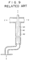
- One conceivable method to create a larger apparatus would involve arranging many parallel reaction tubes equipped with hydrogen permeation tubes in the reforming catalyst layer, such as the one shown in Figure 9, and linking each inlet and outlet of these tubes with headers, so as to form a multi-tube reaction apparatus.
- This apparatus would have a large and complex structure, with low efficiency, low controllability and low heat efficiency. Constructing such a system would also require a large quantity of materials and would be difficult, and the equipment would thus be costly and uncompetitive.
- the objective of the invention is to provide an industrial hydrogen producing apparatus having a novel structure, based on a laboratory-scale facility designed to separate and recover hydrogen generated through steam reforming reactions, by letting hydrogen pass through a selective hydrogen-permeable partitioning wall.
- this invention generally provides a hydrogen producing apparatus which comprises:an outer cylinder; an intermediate cylinder; an inner cylinder, the intermediate and inner cylinders being positioned within the outer cylinder in turn so as to be superimposed over one another; a combustion burner disposed toward the inside of the inner cylinder; wherein the intermediate and inner cylinders are joined together at one end to form a closed circular portion, and a first annular space defined by the outer and intermediate cylinders is in communication with a inner cylinder inside space formed inside the inner cylinder; a catalyst layer formed by filling a reforming catalyst in a second annular space defined by the intermediate and inner cylinders; a hydrogen-permeable tube having hydrogen permeability and disposed in the catalyst layer in the second annular space; and a sweep gas tube having an open end and disposed within the hydrogen-permeable tube; whereby a raw material gas is introduced into the reforming catalyst layer in the second annular space so as to convert the raw material gas into hydrogen at a high temperature, the produced hydrogen permeates the
- a hydrogen producing apparatus in which hydrogen produced from a steam reforming reaction is separated and collected by passing through a partitioning wall having selective permeability to hydrogen, said apparatus comprising: an upright outer cylinder having a closed bottom; an intermediate cylinder and an inner cylinder disposed inside the outer cylinder in an upright and superimposed manner, the inner cylinder being inside the intermediate cylinder; a drooping combustion burner located on the ceiling wall of the inner cylinder; wherein the inner and intermediate cylinders define an inner annular space and an annular bottom with lower ends of the inner and intermediate cylinders being joined together, and the outer and intermediate cylinders define an outer annular space which is in communication with an inner cylinder inside space formed inside the inner cylinder at bottom portions of the cylinders; a catalyst layer formed by filling a reforming catalyst in the inner annular space; a plurality of hydrogen-permeable tubes having a hydrogen-permeable metal membrane on an inorganic porous layer, and the hydrogen-permeable cylinders being
- a hydrogen producing apparatus in which hydrogen produced from a steam reforming reaction is separated and collected by passing through a partitioning wall having selective permeability to hydrogen
- said apparatus comprising: an upright outer cylinder having a closed bottom; an intermediate cylinder and an inner cylinder disposed inside the outer cylinder in an upright and superimposed manner, the inner cylinder being inside the intermediate cylinder; a drooping combustion burner located on the ceiling wall of the inner cylinder; a first annular space defined by the outer and intermediate cylinders being in communication with an inner cylinder inside space formed inside the inner cylinder at bottom portions thereof, and the intermediate cylinder and the inner cylinder defining a second annular space having a closed annular bottom formed by joining lower ends of the intermediate and inner cylinders; a catalyst layer formed by filling a reforming catalyst in the second annular space; wherein a double-walled hydrogen-permeable cylinder has a hydrogen-permeable metal membrane on an inorganic porous layer and has outer, inner, and
- a hydrogen producing apparatus in which hydrogen produced from a steam reforming reaction is separated and collected by passing through a partitioning wall having selective permeability to hydrogen
- said apparatus comprising: an upright outermost cylinder having a closed bottom; an outer cylinder, an intermediate cylinder and an inner cylinder disposed inside the outermost cylinder in an upright and superimposed manner, the inner cylinder being located inside the intermediate cylinder, the intermediate cylinder being located inside the outer cylinder, and the inner cylinder and the outer cylinder being joined together at their bottom ends so as to form a closed annular bottom; a drooping combustion burner located on the ceiling wall of the inner cylinder; a first annular space defined by the outermost and outer cylinders being in communication with an inner cylinder inside space formed inside the inner cylinder at bottom portions thereof, and a second annular space defined by the outer and intermediate cylinders being in communication with a third annular space defined by the intermediate and inner cylinders at bottom portions thereof; a catalyst layer formed by filling a
- a hydrogen producing apparatus in which hydrogen produced from a steam reforming reaction is separated and collected by passing through a partitioning wall having selective permeability to hydrogen
- said apparatus comprising: an upright outermost cylinder having a closed bottom; an outer cylinder, an intermediate cylinder and an inner cylinder disposed inside the outermost cylinder in an upright and superimposed manner, the inner cylinder being located inside the intermediate cylinder, the intermediate cylinder being located inside the outer cylinder, and the inner cylinder and the outer cylinder being joined together at their bottom ends so as to form a closed annular bottom; a drooping combustion burner located on the ceiling wall of the inner cylinder; wherein a first annular space defined by the outermost and outer cylinders is in communication with an inner cylinder inside space formed inside the inner cylinder at bottom portions thereof, and a second annular space defined by the outer and intermediate cylinders is in communication with a third annular space defined by the intermediate and inner cylinders at bottom portions thereof; first and second catalyst layers formed by fill
- a hydrogen producing apparatus in which hydrogen produced from a steam reforming reaction is separated and collected by passing through a partitioning wall having selective permeability to hydrogen
- said apparatus comprising: an upright outer cylinder closed at a top thereof with a ceiling wall; an intermediate cylinder and an inner cylinder disposed inside the outer cylinder in an upright and superimposed manner, the inner cylinder being located inside the intermediate cylinder; an upright combustion burner located on the bottom wall of the inner cylinder, the burner producing upwardly directed flame; wherein the intermediate and inner cylinders define an inner annular space and form a close annular connecting top portion with top ends of the intermediate and inner cylinder being joined together, and an outer annular cylinder defined by the outer and intermediate cylinders is in communication with an inner cylinder inside space formed inside the inner cylinder at top portions thereof; a catalyst layer formed by filling a reforming catalyst in the inner annular spaces; a plurality of hydrogen-permeable cylinders having a hydrogen-permeable metal membrane on an inorganic por
- a hydrogen producing apparatus in which hydrogen produced from a steam reforming reaction is separated and collected by passing through a partitioning wall having selective permeability to hydrogen
- said apparatus comprising: an upright outer cylinder closed at a top thereof with a ceiling wall; an intermediate cylinder and an inner cylinder disposed inside the outer cylinder in an upright and superimposed manner, the inner cylinder being inside the intermediate cylinder; an upright combustion burner located on the bottom wall of the inner cylinder, the burner producing upwardly directed flame; wherein a first annular space defined by the outer and intermediate cylinders is in communication with an inner cylinder inside space formed inside the inner cylinder at top portions thereof, and the intermediate and inner cylinders define a second annular space having a closed annular top formed by joining upper ends of the intermediate and inner cylinders; a catalyst layer formed by filling a reforming catalyst in the second annular space; a double-walled hydrogen-permeable cylinder having a hydrogen-permeable metal membrane on an inorganic porous layer and
- a hydrogen producing apparatus in which hydrogen produced from a steam reforming reaction is separated and collected by passing through a partitioning wall having selective permeability to hydrogen
- said apparatus comprising: an upright outer cylinder closed at a top thereof with a ceiling wall; an outer cylinder, an intermediate cylinder and an inner cylinder disposed inside the outermost cylinder in an upright and superimposed manner, the inner cylinder being located inside the intermediate cylinder, the intermediate cylinder being located inside the outer cylinder, and the inner cylinder and the outer cylinder being joined together at their bottom ends so as to form a closed annular bottom; an upright combustion burner located on the ceiling wall of the inner cylinder, the burner producing upwardly directed flame; wherein a first annular space defined by the outermost and outer cylinders is in communication with an inner cylinder inside space formed inside the inner cylinder at top portions thereof, and a second annular space defined by the outer and intermediate cylinders is in communication with a third annular space defined by the intermediate and inner cylinders at top portions thereof;
- the raw material gas to be introduced into the hydrogen producing apparatus according to this invention is a mixture of steam, an alcohol such as methanol, and light hydrocarbons such as natural gas, naphtha and town gas.
- the reforming catalyst used in this invention can be any convention catalyst for the steam reforming manufacture of hydrogen from the above mentioned raw material gas.
- the hydrogen producing apparatus has a vertical furnace formed with the inner cylinder.
- the structure includes layered cylinders incorporating upright intermediate and outer cylinders disposed outside the inner cylinder.
- the apparatus sometimes has an outermost cylinder disposed outside outer, intermediate and inner cylinders.
- the inner annulus contains a catalyst layer filled with reforming catalyst. Installing hydrogen-permeable tubes (or double-walled hydrogen-permeable tubes in some cases) in the catalyst layer creates a reaction/separation process region. Cylindrical structures are preferable, because they ensure uniform thermal flux distribution in the radius direction within the structure of concentric, layered cylinders, with the furnace located in the center. This prevents the generation of hot spots at which temperature may exceed the limit the hydrogen permeation tubes can withstand.
- the raw material gas (process feed gas) is introduced into the inner annular space by means of conventional methods.
- the gas is modified into hydrogen when passing through the reforming catalyst layer.
- the hydrogen thus generated permeates the hydrogen-permeable tubes and is swept along with sweep gas, introduced from the annulus formed between the hydrogen-permeable tube and the sweep gas tube.
- a typical method to introduce and dissipate the process feed gas would include arranging circular pipe headers with multiple spray nozzles around the circumference of the lower section of the inner annulus.
- the endothermic steam reforming reaction absorbs heat, necessitating a drooping combustion burner installed in the ceiling of the internal cylinder or an upright combustion burner install on the bottom thereof.
- the drooping combustion burner is designed with its flames directed downward, and conventional burners can be used for this purpose.
- the upright combustion burner produces upwardly directed flames, and conventional burners can also be used as this type of burner.
- Installing a drooping combustion burner in the top section of the furnace lessens burner stains, reduces burner cleaning requirements, and simplifies inspection and maintenance. As no space needs to be provided below the burner's floor for burner inspection and maintenance, the total height of the furnace can be reduced, resulting in cost savings for the manufacture of the whole hydrogen producing apparatus.
- the combustion gas descends inside the inner cylinder and enters an annulus from the base of the inner cylinder. While ascending, the combustion gas heats the reforming catalyst layer in the internal annulus, and exits from the upper section of the external annulus. Heating the reforming catalyst layer from both sides ensures more uniform heating.
- An upright combustion burner installed in the base of the furnace will have upwardly directed flames, complying with the flame buoyancy direction and with the combustion gas flow direction, thereby improving flame stability.
- the combustion gas rises in the space inside the inner cylinder, then enters the top of the external annulus. As it descends, the combustion gas heats the catalyst layer in the internal annulus, and exits from the lower section of the external annulus.
- the internal annulus catalyst layer is also heated uniformly as heat is applied from both sides.
- the hydrogen-permeable tube is equipped with a hydrogen-permeable metal membrane on a porous inorganic layer.
- the tube selectively allows hydrogen to permeate.
- the reaction apparatus, incorporating the hydrogen-permeable tube, is called a membrane reactor, and this technology is already known.
- the double-walled hydrogen-permeable cylinders used in this invention have inner and outer walls, and are designed to make the membrane reactor more economical.
- Methane is employed as a typical hydrocarbon to explain the operation of the hydrogen-permeable tube.
- the methane reforming reaction progresses at a reaction temperature of 500-1000°C until chemical equilibrium is reached.
- the reaction equation is: CH4 + H2O ⁇ 3H2 + CO
- the conversion is encouraged at the same temperature by separating the generated hydrogen from generated products via the hydrogen-permeable tube, or by reducing the hydrogen partial pressure in the generated products, because according to the above equation, the chemical reaction proceeds further to the right hand side. In other words, the conversion efficiency can therefore be increased without a rise in reaction temperature.
- conventional methane reforming methods require a reaction temperature of about 800°C
- the hydrogen producing apparatus according to this invention makes it possible to obtain the same conversion ratio at 500-600°C, utilizing hydrogen-permeable tubes or cylinders.
- the amount (Q H ) of hydrogen permeating per square centimeter of the hydrogen-permeable metal membrane on the hydrogen-permeable tube is proportional to the difference between the square roots of the partial pressures of hydrogen before and after passing the membrane: (Ph) 1/2 - (Pl) 1/2 .
- Q H k ⁇ (Ph) 1/2 - (Pl) 1/2 ⁇ , where K is a constant.
- the sweep gas flows in the opposite direction.
- the hydrogen partial pressure is therefore significantly lowered because the generated hydrogen is almost completely swept in the area close to the catalyst layer outlet.
- Introducing the sweep gas improves the conversion efficiency of the entire reforming catalyst layer.
- the generated hydrogen collection efficiency is improved by the counter-current material transfer caused by the sweep gas in the hydrogen-permeable tube and reforming gas in the catalyst layer.
- Steam and inert gases such as nitrogen and helium can be used as the sweep gas in this hydrogen producing apparatus.
- the amount of hydrogen which permeates the hydrogen-permeable tube can be increased by raising the difference between the partial pressures of hydrogen on the prepermeation and after-permeation sides. This is done by circulating sweep gas on the after-permeation side to reduce the partial pressure of hydrogen.
- Other means to reduce the partial pressure of hydrogen on the after-permeation side include the use of a suction pump.
- the hydrogen-permeable metal membrane on the hydrogen-permeable tube selectively allows only hydrogen to permeate.
- the hydrogen separated through the hydrogen-permeable tube is extremely pure, it is suitable for use in the solid fuel molecular cells.
- the 5-50 ⁇ m thick hydrogen-permeable metal membrane is formed on the inorganic porous layer, and is able to selectively permeate hydrogen.
- the inorganic porous layer functions as carrier to support the hydrogen-permeable metal membrane.
- the 0.1-1 mm thick inorganic porous layer is created from materials such as ceramic, glass, or porous stainless steel, non-woven fabric. Single or multi-layer metal mesh is incorporated in the porous layer to boost its structural strength.
- intermediate, outer and outermost upright cylinders can be nested outside the inner cylinder which forms a vertical furnace.
- the first and second catalyst layers are created by filling the second and third annuluses, respectively, with reforming catalyst.
- a reaction/separation region is created by installing a hydrogen-permeable tube in the first catalyst layer.
- cylindrical vessels should be used because the structure of concentric cylinders with the furnace arranged in the center assists a uniform distribution of thermal flux in radial directions and also prevents the development of hot spots where the temperature may exceed the temperature limit of the hydrogen-permeable tube.
- the reformation of hydrocarbons progresses in the second catalyst layer.
- the gas flows into the first catalyst after the temperature and the partial pressure of hydrogen reach maximum values near the catalyst layer outlet.
- the reforming reaction progresses further as hydrogen is extracted through the hydrogen-permeable tube.
- the partial pressure of hydrogen in the raw material gas significantly drops as it moves toward the outlet of the first catalyst layer. Therefore, the partial pressure of hydrogen is generally lower in the first catalyst layer.
- the temperature of the second catalyst layer is somewhat higher around the inner cylinder than in the first catalyst layer because the inner cylinder forms the furnace wall in the center and is heated.
- the distribution of temperature, hydrogen partial pressure, and gas composition varies in each catalyst layer. It is therefore preferable to select catalysts which are active and durable under the conditions found in each catalyst layers.
- a catalyst suitable for both the first and second catalyst layers is actually available, a single catalyst may be used in both catalyst layers.
- the raw material gas (process feed gas) is introduced through the upper section of the third annulus and converted into hydrogen at high temperatures, as it flows through the second catalyst layer. This gas then flows into the bottom section of the first catalyst layer, where any gas which has not reacted is converted into hydrogen.
- the generated hydrogen passes through the hydrogen-permeable tube for selective separation and collection.
- the sweep gas enters the upper part of the annulus created between the hydrogen-permeable tube and the sweep gas tube. The sweep gas and hydrogen flow through the sweep gas tube and out of the hydrogen outlet.
- the process feed gas is reformed into hydrogen at a high conversion efficiency as it passes through the high temperature second catalyst layer, which is located in the third annulus immediately inside the inner furnace cylinder composing a furnace.
- the reformed hydrogen is separated and collected through a hydrogen-permeable tube in the second annulus. Any portion of process feed gas which has not reacted is reformed in the first catalyst layer. Thus, the overall conversion efficiency is significantly improved.
- hydrogen is generated in the second catalyst layer, but is not separated or collected through the hydrogen-permeable tubes there. Therefore, the partial pressure of hydrogen in the product gas rises at the outlet of the second catalyst layer; that is, at the inlet of the first catalyst layer. This increases forces to transfer substances to improve the efficiency of separation and collection of hydrogen through the hydrogen-permeable tube in the first catalyst layer. It is therefore possible to reduce the area allotted for gas permeation.
- the reforming catalyst layer and the hydrogen-permeable tube also have to be taller.
- the difference in thermal expansion between the reforming catalyst layer and the hydrogen-permeable tube becomes significant.
- the consequent friction between the reforming catalyst layer and the hydrogen-permeable tube may cause the reforming catalyst to become powder due to friction.
- the upper part of the hydrogen-permeable tube is fixed while the lower end is left free, permitting movement at the lower end. This causes notable powdering of the reforming catalyst as it is pressed and destroyed.
- the upper end of the hydrogen-permeable tube in the hydrogen producing apparatus is free while its lower section is fixed. This eliminates pressure on or destruction of the reforming catalyst for taller hydrogen producing apparatuses, thereby reducing the likelihood of the reforming catalyst powdering as a result of friction.
- the reforming catalyst layer can therefore be taller than in conventional apparatuses, enabling use of a comparatively low strength reforming catalyst in a large hydrogen producing apparatus.
- the hydrogen-permeable metallic membrane should preferably be made of a non-porous layer of an alloy containing Pd, V or N, such as: Pd-containing alloys including Pd-Ag alloys, Pd-Y alloys, Pd-Ag-Au alloys; V-containing alloys including V-Ni alloys and V-Ni-Co alloys; and Ni-containing alloys including LaNi5 alloys.
- Pd-containing alloys including Pd-Ag alloys, Pd-Y alloys, Pd-Ag-Au alloys
- V-containing alloys including V-Ni alloys and V-Ni-Co alloys and Ni-containing alloys including LaNi5 alloys.
- a suitable manufacturing method for the non-porous Pd layer is disclosed in US Patent Nos. 3,155,467 and 2,773,561.
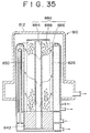
- a cylindrical radiating body should be placed to surround the frame formed by the combustion burner flame within the inner cylinder.
- the radiating body radiates heat to raise the temperature of the reforming catalyst layer, and this ensures the required heat flux is available and undesirable partial or uneven heating of the hydrogen-permeable tube is avoided. This also makes it possible to maintain a uniform temperature distribution of the reforming catalyst layer.
- the temperature of the hydrogen-permeable tube should not be raised above 800°C because of its heat resistance characteristics.
- the radiating body should preferably have a porous wall so that the combustion gas can flow through the porous wall to efficiently heat the radiating body.
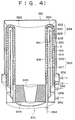
- a dual arrangement comprising an inner cylindrical radiating body and an outer cylindrical radiating body is preferred as another example of the radiating body arrangement.
- the combustion gas flows down inside the inner cylindrical radiating body, and then up the annulus created by the inner and outer radiating bodies, and down again in a space between the outer cylindrical radiating body and the inner cylinder mentioned above, so as to efficiently heat the radiating bodies.
- the vertical flow of the combustion gas is turned up side down as compared with the first to fourth aspects of the invention because the general arrangement of the whole apparatus including the burner is turned that way.
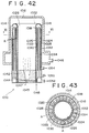
- the radiating body is preferably cylindrical and has an opening in its lower part, and the top of the radiating body is spaced apart from the ceiling of the inner cylinder.
- the combustion gas can flow downward inside the radiating body, and a part of the gas flows upward in an annular space defined by the inner cylinder and the radiating body via the opening, and the gas flows down again inside the radiating body via the gap formed between the top of the radiating body and the ceiling of the inner cylinder, so as to circulate the inside and outside of the radiating body.
- the radiating body is preferably cylindrical and has an opening in its upper part, and the bottom of the radiating body is spaced apart from the bottom of the inner cylinder.
- the combustion gas can flow upward inside the radiating body, and a part of the gas flows downward in an annular space defined by the inner cylinder and the radiating body via the opening, and the gas flows up again inside the radiating body via the gap formed between the bottom of the radiating body and the bottom of the inner cylinder, so as to circulate the inside and outside of the radiating body.
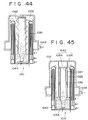
- An alternative embodiment of the invention is a column-shaped catalytic combustion apparatus in the inner cylinder in place of the combustion burner.
- the catalytic combustion apparatus serves as a combustion burner as well as a radiating body, and can heat the reforming catalyst layer uniformly.
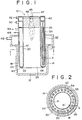
- Figure 1 is an schematically illustrated sectional view of one embodiment of the hydrogen producing apparatus according to the first aspect of the invention.
- Figure 2 is an outlined transverse sectional view along the line I-I on the apparatus shown in Figure 1.
- Figures 1 and 2 show the hydrogen producing apparatus 10, an outer cylinder 14 with a closed base 12, and an intermediate cylinder 18 and inner cylinder 20 installed in a concentric manner within the outer cylinder.
- the outer cylinder 14, intermediate cylinder 18 and inner cylinder 20 form an upright, cylindrical structure.
- the lower sections of the inner cylinder 20 and the intermediate cylinder 18 are connected to each other, forming a closed annular base section 22.
- the walls of the outer cylinder 14 and the intermediate cylinder 18 create an outer annulus 24.
- the outer annulus 24 and the space 26 within the inner cylinder 20 are connected at their bottoms.
- the intermediate cylinder 18 and inner cylinder 20 create an inner annulus 30.
- a route for the combustion gas is created by continuous paths going from the inner cylinder 26, through the gap between the bottom section 12 and the annular base 22 of the outer cylinder 14, and to the outer annulus 24.
- the side wall and the bottom wall 12 of the outer cylinder 14 are constructed of fire resistant bricks.
- the catalyst layer 30 in the inner annulus 30 (for convenience, we use the same numeral for both components) is filled with reforming catalyst A.
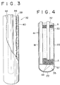
- Figure 2 shows a number of cylindrical hydrogen-permeable tubes 32 in the catalyst layer 30.
- the tubes are equipped with hydrogen-permeable metal membrane on an inorganic porous layer and positioned vertically around the circumference of the inner annulus 30.
- Cylindrical, stainless steel sweep gas tubes 34 are installed in a concentric manner within the hydrogen-permeable tube 32.
- the hydrogen-permeable tube 32 has a closed base and has an external diameter of about 20 mm. It also has an internal support material made of stainless steel mesh 36. An inorganic porous layer 38 made of stainless steel non-woven cloth is disposed around the mesh 36 and acts as a supporting frame for the hydrogen-permeable metal membrane, which is essentially a coated non-porous Pd-based alloy membrane 40.
- the hydrogen-permeable tubes in each embodiment which will be discussed in the following share a similar structure.
- the process feed gas enters the lower section of the inner annulus 30 through an introduction tube 41 running from the raw material gas inlet 48 to the reforming catalyst layer 30 of the inner annulus 30.
- the tube extends to the bottom of the inner annulus 30.
- the tube 41 is connected to an annular pipe header 43, which has many spray nozzles at its bottom.
- Figure 4 shows an alternate distribution means in which an annular space 55 is formed by partitioning the bottom portion of the inner annuls with a partitioning plate 57, and the raw material gas introduction tube 41 is connected to the annular space 55. Many small penetration pores 49 are formed in the partitioning plate 57.
- a drooping combustion burner 44 with a downward-facing burner is installed on the ceiling 42 of the top section of the inner cylinder 26.
- the combustion burner 44 is connected to a fuel gas tube 45 and an air intake tube 47.
- the drooping combustion burner 44 burns fuel gas introduced via a fuel gas tube 45, uses air taken in via an air intake tube 47, and maintains the prescribed temperatures by supplying the heat energy necessary for the steam reforming reaction in the reforming catalyst layer 30.
- the combustion gas flows inside the inner cylinder 26, through the space created between the base 12 of the outer cylinder 14 and its annular bottom 22, then through the outer annulus 24, and is emitted from the combustion gas outlet 46. During this process the combustion gas heats both sides of the catalyst layer of the inner annulus 30, thereby maintaining a uniform temperature distribution.
- the process feed gas is a mixture of either light hydrocarbons or methanol and steam.
- the gas flows through the raw material gas introduction tube 41, the pipe header 43, the bottom section of the inner annulus 30, then into the reforming catalyst layer 30.
- the raw material gas is converted into hydrogen at a high temperature.
- the generated hydrogen is selectively separated and collected via the hydrogen-permeable tubes 32.
- the hydrogen and the sweep gas exit via the hydrogen outlet 52 in the upper part of the tubes 32.
- the sweep gas is fed from the sweep gas inlet 50 located in the top part of the apparatus 10.
- the gas flows down through the annulus 33 between the sweep gas tube 34 and the hydrogen-permeable tube 32, and flows into the open lower end of the sweep gas tube 34, sweeping the hydrogen as it flows down.
- the gas and generated hydrogen rise and flow out of the hydrogen outlet 52.
- Steam or an inert gas, for example, can be used as the sweep gas.
- the reforming catalyst layer 30 is heated from both sides, thereby maintaining a more uniform temperature distribution. This also prevents local overheating in the hydrogen-permeable tube.
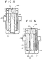
- a cylindrical radiating body 62 is installed in the inner cylinder space 26 of the hydrogen producing apparatus 60 so as to surround the flame of the drooping combustion burner 44 as shown in Figure 5.
- the radiating body 62 has a cylindrical structure with porous walls.
- the combustion gas from the combustion burner 44 permeates the porous walls and flows out into the inner cylinder space 26.
- the combustion gas heats the radiating body 62 during this process, ensuring a virtually uniform temperature distribution.
- the heated radiating body 62 heats the reforming catalyst layer 30 evenly, with an almost uniform heat flux.
- the hydrogen producing apparatus 60 in Figure 6 has another radiating body 62 which is a modification of what is shown in Figure 5.
- the radiating body assembly 62 in Figure 6 forms a dual cylindrical structure composed of inner and outer cylinder radiating bodies 64 and 66.
- the inner cylinder radiating body 64 is in contact with the ceiling 42 of the inner cylinder 20, there is a gap between it and the bottom 12 of the outer cylinder 14.
- the outer cylinder radiating body 66 is in contact with the bottom 12, but is spaced apart from the ceiling 42.
- the combustion gas flows down from the drooping combustion burner 44, through the inner cylinder radiating body 64, then moves up through the annulus 67 between the inner cylinder radiating body 64 and the outer cylinder radiating body 66.
- the gas then flows into the inner cylinder space 26 from the top section of the outer cylinder radiating body 66.
- the combustion gas heats the inner cylinder radiating body 64 and the outer cylinder radiating body 66 during this process, creating a substantially uniform overall temperature distribution.
- the heated inner cylinder radiating body 64 and outer cylinder radiating body 66 heat the reforming catalyst layer 30 in an even manner with substantially uniform heat flux.
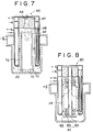
- the hydrogen producing apparatus 60 in Figure 7 illustrates another modification of the radiating body 62 shown in Figure 5.
- the radiating body 62 in Figure 7 is cylindrical and constructed of fire resistant bricks. There is a gap 68 between the top section of the radiating body 62 and the ceiling 42 of the hydrogen producing apparatus 60.
- the bottom section of the radiating body 62 has openings 70.
- the combustion gas flows down from the drooping combustion burner 44 to the radiating body 62, and flows through the openings 70 at the bottom. A portion of the combustion gas moves upward in the annulus 72 between the inner cylinder 20 and the radiating body 62, and circulates by flowing into the radiating body 62 via the gap 68. The temperature of the radiating body 62 is maintained at a uniform level by this process. The heated radiating body 62 heats the reforming catalyst layer 30 in an even manner, with substantially uniform heat flux.
- the hydrogen producing apparatus 80 in Figure 8 is a modification of the hydrogen producing apparatus 10 in Figure 1.
- a column-shaped catalyst burner 82 is installed in the inner cylinder space 26.
- the catalyst burner 82 comprises an internal tube 84 to introduce fuel gas and air, an external mesh tube 86 surrounding the internal tube 84, and a combustion catalyst layer 88 between these tubes 84, 86.
- Fuel gas burned in the combustion catalyst layer 88 heats the catalyst burner 82 to a uniform temperature.
- the heated catalyst burner 82 heats the reforming catalyst layer 30 in an even manner, with substantially uniform heat flux resulting.
- Figure 1 illustrates the hydrogen producing apparatus 10, the structure of the reaction apparatus with effective length of 600 mm, and is made up of components with the following dimensions: the internal diameter of the inner cylinder 20 is 100 mm; the internal diameter of the intermediate cylinder 18 is 173 mm; the internal diameter of the outer cylinder 14 is 188 mm; the external diameter of the hydrogen-permeable tube 32 is 20 mm; and the external diameter of the sweep gas tube 34 is 6 mm.
- the hydrogen-permeable tubes 32 are placed in an equidistant manner around the circumference of the catalyst layer in the inner annulus 30.
- a conventional reformer which does not employ hydrogen-permeable and has the barrier of chemical equivalence based on the relationship between the operating temperature and pressure achieved a conversion efficiency of about 24% at this reaction temperature.
- the raw material gas flows up from the bottom part of the inner annulus, to the reformer catalyst layer.
- the sweep gas is introduced from the top section of the annulus created between the hydrogen-permeable tube and the sweep gas tube. This gas passes into the sweep gas tube with the hydrogen, and is extracted from the top part of the tube.
- the same effect can be obtained by reversing the raw material gas and sweep gas flow directions.
- Figure 10 is an perspective sectional view of embodiment 4 for the hydrogen producing apparatus according to the second aspect of the invention.
- Figure 11 is an typical vertical sectional view of the apparatus shown in Figure 10.
- Figures 10 and 11 show the hydrogen producing apparatus 110 equipped with an outer cylinder 114 with a bottom section 112, and with an intermediate cylinder 116 and an inner cylinder 118, both of which are installed in a concentric manner within the outer cylinder.
- the outer cylinder 114, intermediate cylinder 116 and inner cylinder 118 are all upright.
- the outer cylinder 114 and intermediate cylinder 116 create the first annulus 120 between their walls.
- the first annulus 120 and the inner cylinder space 122 in the inner cylinder 118 are connected at their bottom portions.
- the lower sections of the intermediate cylinder 116 and inner cylinder 118 are connected, creating a closed annulus 124.
- These cylinders create a second annulus 126 between their walls.
- a flow route for the combustion gas starts in the inner cylinder 122, passes through a space between the bottom section 112 of the outer cylinder 114 and the annular bottom 124 to the first annulus 120.
- the outer cylinder wall 114 and bottom wall 112 are both constructed of fire resistance bricks.
- the catalyst layer 126 in the second annulus 126 (the same numeral is used here for convenience) is filled with reforming catalyst A.
- a double-walled hydrogen-permeable cylinder 134 is composed of an internal wall 130, an annular bottom wall 132, and an external wall 128 which is made of an inorganic porous layer on which a hydrogen-permeable metallic membrane is disposed.
- the double-walled hydrogen-permeable cylinder 134 which has the third annulus 133 formed between its two walls is installed in a concentric manner in the second annulus 126.
- the double-walled hydrogen-permeable cylinder 134 contains many stainless steel cylindrical sweep gas tubes 136, installed in an equidistant manner around the circumference of the third annulus 133 of double-walled hydrogen-permeable cylinder 134.
- Figure 12 shows the external wall 128 of the double-walled hydrogen-permeable cylinder 134, its internal wall 130 and the annular bottom wall 132, all having stainless steel mesh 138 supporting material on their inside.
- An inorganic porous layer 140 of stainless steel non-woven fabric lies on top of the mesh, as a frame for the hydrogen-permeable metallic membrane.
- a non-porous Pd membrane 142 is coated on top of the fabric to form the hydrogen-permeable metallic membrane.
- a downward-facing drooping combustion burner 146 is installed in the ceiling 144 of the inner cylinder 122. This combustion burner 146 is connected to a fuel gas tube 148 and an air intake tube 150.
- the drooping combustion burner 146 uses air from the air intake tube 150 to burn fuel gas introduced via the fuel gas tube 148. The burner thereby supplies the heat energy required for the steam reforming reaction in the catalyst layer 126, and maintains the temperature of the layer at the prescribed level.
- the combustion gas flows into the inner cylinder space 122, the space between the bottom section 112 and the annular section 124 of the outer cylinder 114, and the first annulus 120. It is then exhausted via the combustion gas outlet 152. The gas heats the catalyst layer 126 during this process.
- the raw material gas comprises a mixture of steam and light hydrocarbons or methanol gas. It is introduced via the raw material gas inlet 154 in the top section of the second annulus 126. The gas flows into the catalyst layer 126 and is converted into hydrogen at high temperatures.
- the generated hydrogen is selectively separated and collected through double-walled hydrogen-permeable cylinders 134.
- the sweep gas and hydrogen pass through the third annulus 133 and exhaust through the hydrogen outlet 156 in the top section of the third annulus 133.
- the sweep gas enters through the sweep gas inlet 158 in the top section of the apparatus.
- the sweep gas flows down the sweep gas tube 136 and then into the third annulus 133 through the opening in the lower end. It then sweeps the generated hydrogen, as it rises, and exits via the hydrogen outlet 156.
- Extracting the hydrogen and sweep gas facilitates maintenance of a lower partial pressure of hydrogen on the after-permeation side of the hydrogen-permeable tube.
- Steam or inert gas can be used as sweep gas.
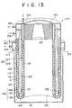
- Figure 13 shows an perspective sectional view of the apparatus 110 in embodiment 5 according to the second aspect of the invention.
- Figure 14 is a transverse cross sectional view of the apparatus 110 shown in Figure 13.
- the apparatus 110 differs from embodiment 1 in the following points.
- the sweep gas tube structure is different in that only four sweep gas tubes 136, a relatively small number of the tubes, are installed in the third annulus 133 of the double-walled hydrogen-permeable cylinder 134. These tubes are connected to the annular pipe header 139 in the lower section 137 of the annular bottom wall 132 of the double-walled hydrogen-permeable cylinder 134.
- the annular pipe header 139 has many penetration pores (not illustrated) which perforate the header wall.
- the catalyst layer 126 comprises an inner catalyst layer 127 in the annulus created by the inner cylinder 118 and the inside wall 30 of the double-walled hydrogen-permeable cylinder 134, and an outer catalyst layer 129 in the annulus created by the intermediate cylinder 116 and the outside wall 128 of the double-walled hydrogen-permeable cylinder 134.
- raw material gas process feed gas enters through the raw material gas inlet 154 in the top section of the inner catalyst layer 127, and flows down to the inner catalyst layer 127. As it moves up through the outer catalyst layer 129, the gas is converted into hydrogen at high temperatures. The generated hydrogen gas is selectively separated by the double-walled hydrogen-permeable cylinders 134. Sweep gas collects the hydrogen, and passes through the penetration pores of the annular pipe header 139 and the sweep gas tube 136. The combined gases are expelled via the hydrogen outlet 156 in the top section of the sweep gas tube 136.
- sweep gas is fed from the sweep gas inlet 158 in the top part of the apparatus.
- the sweep gas and hydrogen flow down the annulus 133, through the penetration pores of the annular pipe header 139 and the sweep gas tube 136, and are expelled via the hydrogen outlet 156 in the top part of the sweep gas tube 136.
- the hydrogen producing - apparatus 110 in embodiment 5 has the same structure as the apparatus in embodiment 4.
- the catalyst layer in embodiment 5 is twice as high as that of embodiment 4, and the apparatus in embodiment 5 provides more advantages to the reforming reaction.
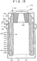
- Figure 15 is an perspective sectional view of embodiment 6 for the hydrogen producing apparatus 210 according to the second aspect of the invention.
- the point of variance from embodiment 5 is that, instead of inserting the sweep gas tubes as indicated in Figure 15, a cylindrical partitioning wall 141 is installed in a concentric manner in the third annulus 133 of the double-walled hydrogen-permeable cylinder 134.
- the sweep gas is fed from the sweep gas inlet 158 in the upper section of the apparatus, flows down the annulus between the partitioning wall 141 and the outside wall 128 of the double-walled hydrogen-permeable cylinder 134, mixing with and sweeping the hydrogen.
- the gas then flows from the lower section of the annulus into the annulus between the partitioning wall 141 and the inside wall 130 of the double-walled hydrogen-permeable cylinder 134, moves up the annulus and passes out through the hydrogen outlet 156 in the upper section.
- the structure of the hydrogen producing apparatus 210 in embodiment 6 is the same as the hydrogen producing apparatus 110 in embodiment 5.
- embodiment 6 has a cylindrical partitioning wall 141 instead of the sweep gas tube found in embodiments 4 and 5, the structure of the apparatus is simpler.
- Figure 10 shows a hydrogen producing apparatus 110.
- the reaction apparatus in Figure 10 has an effective length of 600 mm and is structured as: inner cylinder 118 (internal diameter 100 mm); intermediate cylinder 116 (internal diameter 173 mm); outer cylinder 114 (internal diameter 188 mm); double-walled hydrogen-permeable cylinder 134 (internal diameter 125 mm, external diameter 165 mm); and sweep gas tube 136 (external diameter 6 mm).
- inner cylinder 118 internal diameter 100 mm
- intermediate cylinder 116 internal diameter 173 mm
- outer cylinder 114 internal diameter 188 mm
- double-walled hydrogen-permeable cylinder 134 internal diameter 125 mm, external diameter 165 mm
- sweep gas tube 136 exitternal diameter 6 mm.
- Fifteen upright double-walled hydrogen-permeable cylinders 134 are installed in the catalyst layer of the second annulus 26, equidistant around the circumference.
- Reforming catalyst A is a nickel based catalyst (average particle size: 2 mm in diameter).
- the furnace comprises a drooping burner 146 as shown in Figure 10.
- the outer cylinder 114 is insulated with 200 mm thick rockwool to reduce heat discharge to the external atmosphere.
- a reaction under these above conditions produces 164.0 mole/h of hydrogen, accompanied by sweep gas.
- CO impurity in the hydrogen is less than 1 ppm.
- the conversion efficiency of hydrocarbons in the raw material gas is about 86%.
- the raw material gas flows down the catalyst layer from the top section of the second annulus.
- the sweep gas enters from the upper section of the sweep gas tube then flows upward through the third annulus.
- the gas and hydrogen are extracted from the top part of the annulus.
- the raw material gas enters from the top section of the inner catalyst layer, flows downward through the inner catalyst layer, and moves upward through the outer catalyst layer.
- the sweep gas enters from the top section of the third annulus then flows downward through it.
- the gas and hydrogen are extracted from the upper section of the sweep gas tube.
- the raw material gas enters from the top section of the inner catalyst layer.
- the sweep gas enters from the top part of the annulus between the partitioning wall and the outside wall of the double-walled hydrogen-permeable tube then flows down the annulus.
- the gas and hydrogen are extracted from the top section of the annulus between the partitioning wall and the internal wall of the double-walled hydrogen-permeable tube.
- the same effect can be obtained by reversing the flow direction of raw material gas and sweep gas in embodiments 4 and 6, or by reversing the flow direction of raw material gas and sweep gas or either of these gases in embodiment 5.
- the second aspect of the invention facilitates industrial-scale hydrogen production to economically produce high purity hydrogen, and has the following advantages:
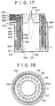
- Figure 16 is the perspective sectional view of embodiment 7 according to the third aspect of the invention.
- the hydrogen producing apparatus 310 is equipped with an outermost outer cylinder 314 with a closed bottom 312.
- An outer cylinder 316, intermediate cylinder 318 and inner cylinder 320 are placed concentrically within the outermost outer cylinder. All four vessels are upright cylinders.
- the lower sections of the inner cylinder 320 and the outer cylinder 316 are connected, forming a closed annular bottom section 322.
- the outermost outer cylinder 314 and the outer cylinder 316 create the first annulus 324 between their cylinder walls.
- the first annulus 324 and the inner cylinder space 326 in the inner cylinder 320 are connected at their bottoms.
- a flow route for the combustion gas starts in the inner cylinder space 326, and passes through a space between the bottom section 312 of the outermost outer cylinder 314 and the annular bottom section 322 to the first annulus 324.
- the outer cylinder 316 and the intermediate cylinder 318 create a second annulus 328 between their cylinder walls.
- the intermediate cylinder 318 and the inner cylinder 320 create a third annulus 330 between them.
- the second annulus 328 and the third annulus 330 are connected at their bottoms.
- the side wall and the bottom of the outermost outer cylinder 314 are constructed of fire resistant bricks.
- the catalyst layer 330 is formed in the third annulus 330 (the same numeral is used for convenience), and filled with reforming catalyst A.
- Figure 18 shows a large number of cylindrical hydrogen-permeable tubes 332 with a hydrogen-permeable metal membrane on an inorganic porous layer. These tubes 332 are installed vertically around the circumference of the third annulus 330 in the catalyst layer.
- the cylindrical stainless steel sweep gas tubes 334 are installed in a concentric manner in the hydrogen-permeable tube 332.
- the tubular hydrogen-permeable tube 332 (or 32) has a closed bottom and an external diameter of about 20 mm as shown.
- the tube contains a supporting material of stainless steel mesh 36.
- On top of the mesh 36 is an inorganic porous layer 38 of non-woven stainless steel fabric, which carries the hydrogen-permeable metal membrane.
- a non-porous Pd-based alloy hydrogen-permeable metal membrane 40 is disposed on top of the fabric.
- Figure 16 shows that the drooping combustion burner 344 faces downward from the ceiling 342 of the inner cylinder space 326.
- the combustion burner 344 is connected to a fuel gas tube 345 and air intake tube 347.
- FIG. 16 to 18 support the following discussion of the processes of the hydrogen producing apparatus 310.
- the fuel gas enters the combustion burner 344 via the fuel gas tube 345 and is burnt with air supplied from the air intake tube 347.
- the prescribed temperature is maintained by supplying the reforming catalyst layer 330 with the heat energy necessary for the steam reforming reaction.
- the combustion gas flows through the space in the inner cylinder 326, then through the space created by the bottom section 312 of the outermost outer cylinder 314 and the annular bottom 322.
- the gas then passes through the first annulus 324 and exhausts via the combustion gas outlet 346.
- the gas preheats the process feed gas which flows in the opposite direction through the second annulus 328.
- the process feed gas is comprised of either light hydrocarbons or a mixture of methanol gas and steam.
- the gas enters via the raw material gas inlet 348 in the top section of the second annulus 328. It flows into the second annulus 328, from the bottom of the annulus into the reforming catalyst layer 330, and is converted into hydrogen at a high temperature.
- the generated hydrogen is selectively collected through the hydrogen-permeable tube 332 and flows, with the sweep gas, through the hydrogen outlet 352 in the top section of the tube.
- the sweep gas enters via the sweep gas inlet 350 in the top section of the apparatus.
- the gas flows down the annulus 333 between the sweep gas tube 334 and the hydrogen-permeable tube 332, sweeps the hydrogen, and enters the lower end opening of the sweep gas tube 334.
- the gas and hydrogen move upward through the sweep gas tube and flow out of the hydrogen outlet 352. This process suppresses the partial pressure of hydrogen on the after-permeation side of the hydrogen-permeable tube 332.
- raw material gas flows into the reforming catalyst layer after being preheated by combustion gas.
- the raw material gas reforms into hydrogen at a high conversion efficiency and the thermal efficiency of the combustion gas improves.
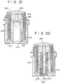
- FIGs 19-21 relate to the following discussion of embodiment 8 according to the third aspect of the invention. Only those parts in these figures which are different from the hydrogen producing apparatus illustrated in Figures 16-18 will be explained.
- the inner cylinder space 426 of the hydrogen producing - apparatus 460 as shown in Figure 19 contains a cylindrical radiating body 462 surrounding the frame from the combustion burner 444.
- This cylindrical radiating body 462 has porous walls.
- the combustion gas of the burner 444 permeates the porous wall and flows into the inner cylinder space 426.
- the combustion gas heats the radiating body 462 during this process, resulting in a uniform overall temperature.
- the heated radiating bodies 462 evenly heats the reforming catalyst layer 430, with almost uniform heat flux.
- the hydrogen producing apparatus 410 in Figure 20 is a modification of the radiating bodies 462 as shown in Figure 19.
- the radiating body assembly 462 shown in Figure 20 has a dual cylinder configuration and comprises an inner cylinder radiating body 464 and an outer cylinder radiating body 466.
- the inner cylinder radiating body 464 is in contact with the ceiling 42 of the inner cylinder 420, but has gaps between it's bottom and the bottom section 412 of the outermost outer cylinder 414.
- the outer cylinder radiating body 466 is in contact with the lower part of the bottom section 412, and its upper section is isolated from the ceiling 442.
- the combustion burner 444 gas flows down through the internal radiating body 464, then moves upward through the annulus 467 between the internal radiating body 464 and the external radiating body 466.
- the gas flows from the upper part of the radiating body 466 into the inner cylinder space 426.
- the combustion gas heats up the inner cylinder radiating body 464 and the outer cylinder radiating body 466 during this process, achieving a uniform overall temperature.
- the heated internal radiating body 464 and external radiating body 466 heat the reforming catalyst layer 430 with an almost uniform heat flux.
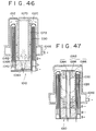
- the hydrogen producing apparatus 460 shown in Figure 21 is another modification of the radiating bodies 462 in Figure 19.
- the cylindrical radiating bodies 462 as shown in Figure 21 are constructed of fire resistant brick.
- the combustion burner 444 gas flows down through the radiating bodies 462, and out through an opening 470 in the lower section of the radiating body. A portion of the combustion gas moves up through the annulus 472 between the inner cylinder 420 and the radiating bodies 462, and returns to the radiating bodies 462 via the gap 468. The combustion gas thoroughly heats the radiating bodies 462 during this process, resulting in an almost uniform overall temperature. The heated radiating bodies 462 evenly heat the catalyst layer 430 with almost uniform heat flux.
- the hydrogen producing apparatus 480 in Figure 22 is a modification of the apparatus 310 in Figure 16 (embodiment 9).
- the apparatus 480 contains a column shaped catalyst burner portion 482 in the inner cylinder space 426 instead of a combustion burner.
- the catalyst burner portion 482 comprises an internal tube 484 which delivers the fuel gas and air and a mesh external tube 486 to surround the internal tube.
- a combustion catalyst layer 488 fills the space between the two tubes.
- the fuel gas is burnt in the combustion catalyst layer 488 and heats the overall catalyst burner portion 482 to a uniform temperature.
- the heated catalyst burner portion 482 evenly heats the reforming catalyst layer 430, with almost uniform heat flux.
- Figure 16 shows the hydrogen producing apparatus 310 which is a reaction apparatus with an effective length of 600 mm. Its dimensions are as follows: the internal diameter of the inner cylinder 20 is 100 mm; the internal diameter of the intermediate cylinder 18 is 174 mm; the internal diameter of the outer cylinder 16 is 183 mm; the internal diameter of the outermost outer cylinder 14 is 200 mm; the external diameter of the hydrogen-permeable tube 32 is 20 mm; and the external diameter of the sweep gas tube 34 is 6 mm.
- Fifteen upright hydrogen-permeable tubes 432 are located in the catalyst layer of the third annulus 430, installed equidistant around the circumference.
- Reforming catalyst A is a nickel based catalyst (average particle size: 2 mm in diameter).
- the furnace comprises a drooping burner 444 as shown in Figure 16.
- the outermost outer cylinder 414 is insulated by 200 mm thick rockwool to reduce head loss to the external atmosphere.
- the CO impurity in the hydrogen is less than 1 ppm.
- the conversion efficiency of hydrocarbons in raw material gas is about 87%.
- the raw material gas flows downward from the top section of the second annulus.
- the gas then flows upward through the catalyst layer in the third annulus.
- the sweep gas enters from the top section of the annulus created between the hydrogen-permeable tube and the sweep gas tube.
- the sweep gas and hydrogen pass through the sweep gas tube and are extracted from its top section. The same effects can be obtained when the raw material gas and sweep gas flow in opposite directions.
- the third aspect of the invention facilitates industrial-scale hydrogen production, economically producing high purity hydrogen, and has the following advantages:
- Figure 23 is an illustrated sectional view of embodiment 10 for the fourth aspect of the present invention.
- Figure 24 is a transverse sectional view at the line VI-VI in Figure 23.
- the hydrogen producing apparatus 510 is equipped with a closed bottom 512 outermost outer cylinder 514. Within this cylinder is a concentric arrangement consisting of an outer cylinder 516, intermediate cylinder 518 and inner cylinder 520. All four vessels are upright cylinders.
- the lower sections of the inner cylinder 520 and the outer cylinder 516 are connected, forming a closed annular bottom 522.
- the outermost outer cylinder 514 and the outer cylinder 516 create the first annulus 524 between their cylinder walls.
- the bottoms of the first annulus 524 and the inner cylinder space 526 within the inner cylinder 520 are connected.
- a flow route of the combustion gas starts in the inner cylinder space 526 and passes through a space between the bottom section 512 of the outermost outer cylinder 514 and the annular bottom section 522 into the first annulus 524.
- the outer cylinder 516 and the intermediate cylinder 518 create a second annulus 528 between their cylinder walls.
- the intermediate cylinder 518 and the inner cylinder 520 create a third annulus 530 between them.
- the bottoms of the second annulus 528 and the third annulus 530 are connected.
- the wall of the outermost outer cylinder 514 and the wall of the bottom section 512 of the outermost external wall 514 are constructed of fire resistant brick.
- the first and second catalyst layer 528 and 530 (for the sake of convenience the same numerals as the second and third annuluses are used) which are filled with reforming catalyst A in the second annulus 528 and the third annulus 530 are created.
- Figure 24 shows a large number of cylindrical hydrogen-permeable tubes 532 with hydrogen-permeable metal membranes on an inorganic porous layer, installed vertically around the circumference of the second annulus 528 in the first catalyst layer 528.
- the cylindrical, stainless steel sweep gas tubes 534 are installed in a concentric manner in the hydrogen-permeable tube 532.
- the tubular hydrogen-permeable tube 532 (or 32) has a closed bottom and an external diameter of about 20 mm.
- the tube contains a supporting material of stainless steel mesh 36.
- On top of the mesh is an inorganic porous layer 38 of woven stainless steel fabric, which carries the hydrogen-permeable metal membrane.
- a non-porous, Pd based alloy, hydrogen-permeable metal membrane 40 is coated on top of the fabric.
- Figure 23 shows that the drooping combustion burner 544 faces downward from the ceiling 542 of the inner cylinder space 526.
- the combustion burner 544 is connected to a fuel gas tube 544 and air intake tube 547.
- FIGS 23 and 24 support the following discussion of the processes of hydrogen producing apparatus 510.
- Fuel gas enters the combustion burner 544 via the fuel gas tube 545, and is burnt in air supplied by the air intake tube 547.
- the prescribed temperature is maintained by supplying to the first and second catalyst 528 and 530 with the heat energy necessary for the steam reforming reaction.
- Combustion gas passes through the inner cylinder space 526 and the space created by the bottom section 512 of the outermost outer cylinder 514 and the annular connection part 522 of the bottom section 512. It then travels through the first annulus 524 and exhausts via the combustion gas outlet 546.
- the process feed gas comprises either light hydrocarbons or a mixture of methanol gas and steam.
- the gas enters via the raw material gas inlet 548 in the top section of the third annulus 530. It flows into the second catalyst layer 530 of the third annulus 530, during which it is converted into hydrogen at a high temperature. The gas then flows into the bottom of the first catalyst layer 528 of the second annulus 528, where any process feed gas which has not reacted is converted into hydrogen.
- the generated hydrogen is selectively collected through the hydrogen-permeable tube 532 installed in the first catalyst layer 528 and flows out, with the sweep gas, through the hydrogen outlet 552 in the top section of the tube.
- the sweep gas enters via the sweep gas inlet 550 in the top section of the apparatus.
- the gas flows down the annulus 533 between the sweep gas tube 534 and the hydrogen-permeable tube 532, sweeps the hydrogen, and enters the lower end opening of the sweep gas tube 534.
- the gas and hydrogen move upward through the sweep gas tube and flow out of the hydrogen outlet 552. This process suppresses the partial pressure of hydrogen on the after-permeation side of the hydrogen-permeable tube 532.
- the process feed gas passes through the high temperature heated catalyst layer 530 immediately inside the inner cylinder 520 which forms the furnace. After the gas is reformed into hydrogen at a high conversion rate, the hydrogen is selectively collected through the hydrogen-permeable tube in the second annulus 528. Any process feed gas which has not reacted is reformed in the reforming catalyst layer 528 in the second annulus 528, significantly improving the conversion efficiency for the entire apparatus.
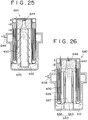
- FIGS 25 and 26 illustrate another embodiment.
- Figure 25 shows an inner cylinder space 626 of the hydrogen producing apparatus 660 which contains a cylindrical radiating body 662 surrounding the drooping combustion burner 644 flame.
- This cylindrical radiating body 662 has porous walls.
- the combustion burner 644 gas permeates the porous wall and flows into the inner cylinder space 626.
- the combustion gas heats the radiating body 662 during this process, resulting in a uniform overall temperature.
- the heated radiating bodies 662 evenly heats the reforming catalyst layer 630, with almost uniform heat flux.
- the hydrogen producing apparatus 660 in Figure 26 is a modification of the radiating bodies 662 shown in Figure 25.
- the radiating body assembly 662 shown in Figure 26 has a dual cylinder configuration and comprises an inner cylinder radiating body 664 and an outer cylinder radiating body 666.
- the inner cylinder radiating body 664 is in contact with the ceiling 642 of the inner cylinder 620, but has gaps between it's bottom and the bottom section 612 of the outermost outer cylinder 614.
- the outer cylinder radiating body 666 is in contact with the bottom section 612, and its upper section is isolated from the ceiling 642.
- the combustion burner 644 gas flows down through the inner cylindrical radiating body 664, then moves upward through the annulus 667 between the inner cylindrical radiating body 664 and the external radiating body 666.
- the gas flows from the upper part of the outer cylindrical radiating body 666 into the inner cylinder space 626.
- the combustion gas heats up the inner cylinder radiating body 664 and the outer cylinder radiating body 666 during this process, achieving a uniform overall temperature.
- the heated internal radiating body 664 and external radiating body 666 heat the reforming catalyst layer 630 with an almost uniform heat flux.
- the hydrogen producing apparatus 660 shown in Figure 27 is another modification of the radiating bodies 662 in Figure 25.
- the cylindrical radiating bodies 662 shown in Figure 27 are constructed of fire resistant bricks. There is a gap 668 between the upper section of the radiating bodies 662 and the ceiling 642 of the hydrogen producing apparatus 660, and an opening 670 in the lower section of the radiating bodies 662.
- the combustion gas flows down through the radiating bodies 662 from the drooping combustion burner 644, and out through an opening 670 in the lower section. A portion of the combustion gas moves up through the annulus 672 between the inner cylinder 620 and the radiating bodies 662, and returns to the radiating body 662 via the gap 668.
- the combustion gas thoroughly heats the radiating bodies 662 during this process, resulting in an almost uniform overall temperature.
- the heated radiating bodies 662 evenly heat the reforming catalyst layer 30, with almost uniform heat flux.
- the hydrogen producing apparatus 680 in Figure 28 is a modification of the apparatus 510 in Figure 23.
- the apparatus 680 contains a column shaped catalyst burner 682 in the inner cylinder space 626, instead of a combustion burner.
- the catalyst burner 682 comprises an internal tube 684 which delivers the fuel gas and air and a mesh external tube 686 to surround the internal tube.
- a combustion catalyst layer 688 fills the space between the two tubes.
- the fuel gas is burnt in the combustion catalyst layer 688 and heats the overall catalyst burner 682 to a uniform temperature.
- the heated catalyst burner 682 evenly heats the reforming catalyst layer 630, with almost uniform heat flux.
- Figure 23 shows a hydrogen producing apparatus 510.
- the reaction apparatus in Figure 23 has an effective length of 600 mm and is structured as: inner cylinder 520 (internal diameter 100 mm); intermediate cylinder 518 (internal diameter 118 mm); outer cylinder 516 (internal diameter 175 mm); outermost outer cylinder 514 (internal diameter 190 mm); hydrogen-permeable tube 532 (external diameter 20 mm); and sweep gas tube 534 (external diameter 6 mm).
- Fifteen upright hydrogen-permeable tubes 532 are installed in the first catalyst layer of the second annulus 528 in an equidistant manner around the circumference.
- Reforming catalyst A is a nickel based catalyst (average particle size: 2 mm in diameter).
- the furnace comprises a drooping burner 544, as shown in Figure 23.
- the outermost outer cylinder 514 is insulated with 200 mm thick rockwool to reduce heat discharge to the external atmosphere.
- a reaction under these above conditions produces 123.0 mole/h of hydrogen, accompanied by sweep gas.
- CO impurity in the hydrogen is less than 1 ppm.
- the conversion efficiency of hydrocarbons in the raw material gas is about 90%.
- the fourth aspect of the invention facilitates industrial-scale hydrogen production, economically producing high purity hydrogen, and has the following advantages:
- Figure 29 is a sectional view of an embodiment according to the fifth aspect of the invention.
- Figure 30 outlines a horizontal section at the line VII-VII on the apparatus shown in Figure 29.
- Figures 29 and 30 show the hydrogen producing apparatus 710 equipped with a covered outer cylinder 714 with a ceiling 712.
- This cylinder contains an intermediate cylinder 718 and inner cylinder 720. All three vessels are upright cylinders.
- the upper sections of the inner cylinder 720 and intermediate cylinder 718 form a closed annulus top section 722.
- the walls of the outer cylinder 714 and intermediate cylinder 718 create an outer annulus 724.
- the upper sections of the outer annulus 724 and inner cylinder space 726 are connected.
- An inner annulus 730 is created between the intermediate cylinder 718 and the inner cylinder 720.
- a flow route for the combustion gas starts in the inner cylinder space 726 and passes through a space between the ceiling 712 of the outer cylinder 714 and the annulus connected top section 722 into the outer annulus 724.
- the wall and the ceiling 714 of the outer cylinder 714 are constructed of fire resistant bricks.
- Reforming catalyst A fills the catalyst layer 730 in the inner annulus 730 (the same numeral is used for convenience).
- Figure 30 shows a large number of cylindrical hydrogen-permeable tubes 732 with hydrogen-permeable metal membranes on an inorganic porous layer, installed vertically around the circumference of the inner annulus 730 in the catalyst layer 730.
- the cylindrical, stainless steel sweep gas tubes 734 are installed in a concentric manner in the hydrogen-permeable tube 732.
- the tubular hydrogen-permeable tube 732 has a closed top part and an external diameter of about 20 mm, as shown in Figure 31.
- the tube contains a supporting material of stainless steel mesh 736.
- On top of the mesh is an inorganic porous layer 738 of woven stainless steel fabric, which carries the hydrogen-permeable metal membrane.
- a non-porous, Pd based alloy, hydrogen-permeable metal membrane 40 is coated on top of the fabric.
- Figure 29 shows the process feed gas structures.
- the raw material gas introduction tube 741 passes from the raw material gas inlet 748, through the reforming catalyst 730 of the inner annulus 730, and injects process feed gas directly into the top section of the inner annulus 730.
- the upper part is connected to the annular pipe header 743, which has many spray nozzles.
- Figure 31 shows another embodiment in which an annular space 755 is created by partitioning the top section of the inner annulus 730 with a partitioning plate 757.
- the raw material introduction tube 741 is connected to the annular space 755.
- Many small penetrated pores 749 can be created in the partitioning plate 757 as a means of distributing the gas.
- An upward facing, upright combustion burner 744 is installed in the bottom section 742 of the inner cylinder space 726.
- the fuel gas tube 745 and air intake 747 are connected to this combustion burner 744.
- FIGS. 29 and 30 support the following discussion of the processes of hydrogen producing apparatus 710.
- Fuel gas enters the upright combustion burner 744 via the fuel gas tube 745, and is burnt in air supplied by the air intake tube 747.
- the prescribed temperature is maintained by supplying to the reforming catalyst layer 730 with the heat energy necessary for the steam reforming reaction.
- Combustion gas passes through the inner cylinder space 726, and the space created by the outer cylinder 714 and the connected annular top section 722 of the ceiling 712. It then moves through the outer annulus 724 and exhausts via the combustion gas outlet 746.
- Both sides of the reforming catalyst A layer of the inner annulus 730 are heated during this period, achieving a uniform temperature.
- the process feed gas comprises light hydrocarbon, a mixture of methanol gas or steam.
- This gas passes through the raw material gas inlet 748 to the raw material gas introduction tube 741 and pipe header 743. It then flows from the top section of the inner annulus 730 into the reforming catalyst layer 730, where the gas is converted into hydrogen.
- the generated hydrogen is selectively separated and collected through the hydrogen-permeable tube 732.
- the hydrogen and sweep gas exhaust from the hydrogen outlet 752 in the lower section of the hydrogen-permeable tube.
- the sweep gas enters via the sweep gas inlet 750 in the top section of the apparatus.
- the gas rises up the dual tube space 733 between the sweep gas tube 734 and the hydrogen-permeable tube 732, sweeps the hydrogen, and enters the top end opening of the sweep gas tube 734.
- the gas and hydrogen move downward through the sweep gas tube and flow out of the hydrogen outlet 752. This process suppresses the partial pressure of hydrogen on the after-permeation side of the hydrogen-permeable tube 732.
- Steam and inert gas are used as sweep gas, for example.
- both sides of the reforming catalyst layer 730 are heated, maintaining a uniform temperature distribution. This prevents local overheating in the hydrogen-permeable tube.
- Figures 32 and 34 illustrate another embodiment. Only points which are different from Figures 29 and 30 will be described, discussions are omitted for the same points of Figures 29 and 30.
- the inner cylinder space 826 of hydrogen producing apparatus 810 contains a cylindrical radiating body 862 surrounding the upright combustion burner 844 flame.
- This cylindrical radiating body 862 has porous walls.
- the combustion burner 844 gas permeates the porous wall and flows into the inner cylinder space 826.
- the combustion gas heats the radiating body 862 during this process, resulting in a uniform overall temperature.
- the heated radiating bodies 862 evenly heats the reforming catalyst layer 830, with almost uniform heat flux.
- the hydrogen producing apparatus 810 in Figure 33 is a modification of the radiating bodies 862 shown in Figure 32.
- the radiating body assembly 862 shown in Figure 33 has a dual cylinder configuration and comprises an inner cylinder radiating body 864 and an outer cylinder radiating body 866.
- the inner cylinder radiating body 864 is in contact with the bottom 842 of the inner cylinder 820, but has gaps between it's upper part and the ceiling 812 of the outermost outer cylinder 814.
- the outer cylinder radiating body 866 is in contact with the ceiling 812 in the top part, and its bottom wall is isolated in the lower part 842.
- the upright combustion burner 844 gas flows up through the inner cylinder radiating body 864, then moves downward through the annulus 867 between the inner cylinder radiating body 864 and the external radiating body 866.
- the gas flows from the lower part of the outer cylindrical radiating body 866 into the inner cylinder space 826.
- the combustion gas heats up the inner cylinder radiating body 864 and the outer cylinder radiating body 866 during this process, achieving a uniform overall temperature.
- the heated internal radiating body 864 and external radiating body 866 heat the reforming catalyst layer 830 with an almost uniform heat flux.
- the hydrogen producing apparatus 810 shown in Figure 34 is another modification of the radiating bodies 862 in Figure 32.
- the cylindrical radiating bodies 862 shown in Figure 34 are constructed of fire resistant brick.
- the combustion gas flows down through the radiating bodies 862 from the upright combustion burner 844, and out through an gap 870 in the upper section. A portion of the combustion gas moves down through the annulus 872 between the inner cylinder 820 and the radiating body 860, and returns to the radiating body 862 via the opening 868.
- the combustion gas thoroughly heats the radiating bodies 862 during this process, resulting in an almost uniform overall temperature.
- the heated radiating bodies 862 evenly heat the reforming catalyst layer 830, with almost uniform heat flux.
- the hydrogen producing apparatus 810 in Figure 35 is a modification of apparatus 710 shown in Figure 29.
- the apparatus 810 contains a column shaped catalyst burner 882 in the inner cylinder space 826, instead of an upright combustion burner.
- the catalyst burner 882 comprises an internal tube 884 which delivers the fuel gas and air, and a mesh external tube 886 to surround the internal tube.
- a combustion catalyst layer 888 fills the space between the two tubes.
- the fuel gas is burnt in the combustion catalyst layer 888 and heats the overall catalyst burner 882 to a uniform temperature.
- the heated catalyst burner 882 evenly heats the reforming catalyst layer 830, with almost uniform heat flux.
- Figure 29 shows a hydrogen producing apparatus 710.
- the reaction apparatus as shown in Figure 29 has an effective length of 600 mm and is structured as: inner cylinder 720 (internal diameter 100 mm); intermediate cylinder 718 (internal diameter 173 mm); outer cylinder 714 (internal diameter 188 mm); hydrogen-permeable tube 732 (external diameter 20 mm); and sweep gas tube 734 (external diameter 6 mm).
- Fifteen upright hydrogen-permeable tubes 732 are installed in the reforming catalyst layer of the inner annulus 730 in an equidistant manner around the circumference.
- Reforming catalyst A is a nickel based catalyst (average particle size: 2 mm in diameter).
- the furnace comprises a upright burner 744, as shown in Figure 29.
- the outer cylinder 714 is insulated with 200 mm thick rockwool to reduce heat discharge to the external atmosphere.
- a reaction under these above conditions produces 180.4 mole/h of hydrogen, accompanied by sweep gas.
- CO impurity in the hydrogen is less than 1 ppm.
- the conversion efficiency of hydrocarbons in the raw material gas is about 83%.
- the raw material gas flows downward through the reforming catalyst layer from the upper section of the inner annulus.
- the sweep gas enters from the lower section of the annulus created between the hydrogen-permeable tube and the sweep gas tube.
- the sweep gas and hydrogen pass through the sweep gas tube and are extracted from its lower section.
- the fifth aspect of the invention facilitates industrial-scale hydrogen production, economically producing high purity hydrogen, and has the following advantages:
- Figure 36 is an perspective sectional view of embodiment 16 for the sixth aspect of the invention.
- Figure 37 is an outlined transverse sectional view of the apparatus in Figure 36.
- Figures 37 and 37 show the hydrogen producing - apparatus 910 equipped with a covered outer cylinder 914 with a ceiling 912, and with an intermediate cylinder 916 and inner cylinder 918, both of which are installed in a concentric manner within the outer cylinder.
- the outer cylinder 914, intermediate cylinder 916 and inner cylinder 918 are all upright cylinders.
- the outer cylinder 914 and intermediate cylinder 916 create the first annulus 920 between their walls.
- the first annulus 920 and the inner cylinder space 922 in the inner cylinder 918 are connected at their top parts.
- the upper sections of the intermediate cylinder 916 and inner cylinder 918 are connected, creating a closed annulus with a connected top part 924.
- These cylinders create a second annulus 926 between their walls.
- a flow route for the combustion gas starts in the inner cylinder 922 and passes through a space between the ceiling 912 of the outer cylinder 914 and the top annulus 924 into the first annulus 920.
- the wall and the ceiling 912 of the outer cylinder 914 are both constructed of fire resistance bricks.
- the catalyst layer 926 in the second annulus 926 (the same numeral is used for convenience) is filled with reforming catalyst A.
- the catalyst layer has an external wall 928, which has a hydrogen-permeable nonporous Pd membrane 942 on an inorganic porous layer 940, an internal wall 930 and an annular top wall 932.
- the double-walled hydrogen-permeable cylinder 934 which creates the third annulus 933 is installed in a concentric manner in the second annulus 926.
- the double-walled hydrogen-permeable cylinder 934 contains many parallel stainless steel cylindrical sweep gas tubes 936, installed around the inner circumference of the third annulus 933 of the double-walled hydrogen-permeable cylinder 934.
- Figure 38 shows the external wall 928 of the double-walled hydrogen-permeable cylinder 934, its internal wall 930 and the annular top wall 932. These walls all contain stainless steel mesh 938 as supporting material.
- An inorganic porous layer 940 of stainless steel non-woven fabric lies on top of the mesh as a frame for the hydrogen-permeable metallic membrane.
- a non-porous Pd membrane 942 is disposed on top of the fabric to form the hydrogen-permeable metallic membrane.
- Figure 36 shows an upright upwardly facing combustion burner 946 installed in the bottom wall 944 of the inner cylinder space 922.
- This combustion burner 946 is connected to a fuel gas tube 948 and an air intake tube 950.
- the upright combustion burner 946 in the bottom wall 944 of the inner cylinder 918 burns gas from the fuel gas tube 948 in air from the air intake tube 950.
- the combustion supplies the heat energy necessary to maintain the temperature required for the steam reforming reaction in the catalyst layer 926.
- the combustion gas flows into the inner cylinder space 922, the space between the ceiling 912 and the annulus with the connected top 924 of the outer cylinder 914, and the first annulus 920. It is then exhausted via the combustion gas outlet 952. The gas heats the catalyst layer 926, which is filled with reforming catalyst A, in the second annulus 926 during this process.
- the raw material gas comprises a mixture of with either steam, light hydrocarbons or methanol gas. It is introduced via the raw material gas inlet 954 in the lower section of the second annulus 926. The gas flows into the catalyst layer 926 and is converted into hydrogen at high temperatures.
- the generated hydrogen is selectively separated and collected through double-walled hydrogen-permeable cylinders 934.
- the sweep gas and hydrogen pass through the third annulus 933 and exhaust through the hydrogen outlet 956 in the lower section of the third annulus 933.
- the sweep gas enters through the sweep gas inlet 958 in the lower section of the apparatus.
- the sweep gas flows up the sweep gas tube 936, then into the third annulus 933 through the opening in the upper end. It then sweeps the hydrogen as it falls, and exits via the hydrogen outlet 956.
- Extracting the hydrogen and sweep gas facilitates maintenance of a lower partial pressure of hydrogen on the after-permeation side of the hydrogen-permeable tube 932.
- Steam and inert gas are used as sweep gas.
- Figure 39 shows an perspective sectional view of the apparatus 910 in embodiment 17 for the sixth aspect of the invention.
- Figure 40 is a transverse sectional view of the apparatus 910 in Figure 39.
- the apparatus 910 differs from embodiment 16 in the following points.
- the sweep gas tube structure is different, as a relatively small number, only four, sweep gas tubes 936 are installed in the third annulus 933 of the double-walled hydrogen-permeable cylinder 934. These tubes are connected to the annular pipe header 939 in the upper section 937 of the annular top wall 932 of the double-walled hydrogen-permeable cylinder 934.
- the annular pipe header 939 has many penetration pores (not illustrated) which perforate the header wall.
- the catalyst layer 926 comprises an inner catalyst layer 927 in the annulus created by the inner cylinder 918 and the internal wall 930 of the double-walled hydrogen-permeable cylinder 934, and an outer catalyst layer 929 in the annulus created by the intermediate cylinder 916 and the external wall 928 of the double-walled hydrogen-permeable cylinder 934.
- the raw material gas enters through the raw material gas inlet 954 in the lower section of the inner catalyst layer 927, and flows upward through the inner catalyst layer 927. As it moves down through the outer catalyst layer 929, the gas is converted into hydrogen at high temperatures.
- the generated hydrogen gas is selectively separated by the double-walled hydrogen-permeable cylinders 934. Sweep gas collects the hydrogen, and passes through the penetration pores of the annular pipe header 939 and the sweep gas tube 936. The combined gases are exhausted via the hydrogen outlet 956 in the lower section of the sweep gas tube 936.
- sweep gas is fed from the sweep gas inlet 958 in the lower part of the apparatus.
- the sweep gas and hydrogen flow up the annulus 933, through the penetration pores of the annular pipe header 939 and the sweep gas tube 936, and exhaust via the hydrogen outlet 956 in the lower part of the sweep gas tube 936.
- the hydrogen producing apparatus 910 in embodiment 17 has the same structure as the apparatus in embodiment 16.
- the catalyst layer in embodiment 17 is twice as high as that of embodiment 16, and the apparatus in embodiment 17 provides more advantages to the reforming reaction.
- Figure 41 is a perspective sectional view of embodiment 18 of the hydrogen producing apparatus 910 for the sixth aspect of the invention.
- the point of variance from embodiment 17 is that, instead of inserting the sweep gas tube as indicated in Figure 41, the cylindrical partitioning wall 941 is installed in a concentric manner in the third annulus 933 of the double-walled hydrogen-permeable cylinder 934.
- the sweep gas is fed from the sweep gas inlet 958 in the lower section of the apparatus, flows up the annulus between the partitioning wall 941 and external wall 928 of the double-walled hydrogen-permeable cylinder 934, mixing with and sweeping the hydrogen.
- the gas then flows from the top section of the annulus into the annulus between the partitioning wall 941 and the internal wall 930 of the double-walled hydrogen-permeable cylinder 934, moves down the annulus and passes out through the hydrogen outlet 956 in the lower section.
- the structure of the hydrogen producing apparatus 910 in embodiment 18 is the same as the hydrogen producing apparatus 910 in embodiment 17.
- embodiment 18 has a cylindrical partitioning wall 941 instead of the sweep gas tube found in embodiments 16 and 17, the structure of the apparatus is simpler.
- Figure 39 shows a hydrogen producing apparatus 910.
- the reaction apparatus in Figure 39 has an effective length of 600 mm and is structured as: inner cylinder 918 (internal diameter 100 mm); intermediate cylinder 916 (internal diameter 173 mm); outer cylinder 914 (internal diameter 188 mm); double-walled hydrogen-permeable cylinder 934 (internal diameter 125 mm and external diameter 165 mm); and sweep gas tube 936 (external diameter 6 mm).
- a double-walled hydrogen-permeable cylinders 934 is installed in the catalyst layer of the second annulus 926.
- Reforming catalyst A is a nickel based catalyst (average particle size: 2 mm in diameter).
- the furnace comprises an upright burner 46 as shown in Figure 39.
- the outer cylinder 14 is insulated with 200 mm thick rockwool to reduce heat discharge to the external atmosphere.
- a reaction under these conditions produces 162.0 mole/h of hydrogen, accompanied by sweep gas.
- CO impurity in the hydrogen is less than 1 ppm.
- the conversion efficiency of hydrocarbons in the raw material gas is about 85%.
- the raw material gas flows up the catalyst layer from the lower section of the second annulus.
- the sweep gas enters from the lower section of the sweep gas tube then flows down through the third annulus.
- the gas and hydrogen are extracted from the lower part of the annulus.
- the raw material gas enters from the lower section of the inner catalyst layer, flows up through the inner catalyst layer, and moves down through the outer catalyst layer.
- the sweep gas enters from the lower section of the third annulus then flows up through it.
- the gas and hydrogen are extracted from the lower section of the sweep gas tube via an annular pipe header.
- the raw material gas enters from the lower section of the inner catalyst layer.
- the sweep gas enters from the lower part of the annulus between the partitioning wall and the external wall of the double-walled hydrogen-permeable tube then flows up the annulus.
- the gas and hydrogen are extracted from the lower section of the annulus between the partitioning wall and the internal wall of the double-walled hydrogen-permeable tube.
- the same effect can be obtained by reversing the flow direction of the raw material gas and sweep gas in embodiments 17 and 19, or by reversing the flow direction or either of these gases in embodiment 18.
- the sixth aspect of the invention facilitates industrial-scale hydrogen production, economically producing high purity hydrogen, and has the following advantages:
- Figure 42 is an illustrated sectional view of embodiment 19 for the hydrogen producing apparatus according to the seventh aspect of the invention.
- Figure 43 is a transverse sectional view at the line XI-XI in Figure 42.
- the hydrogen producing apparatus 1010 is equipped with a covered outermost outer cylinder 1014 with a ceiling 1012. Within this cylinder is a concentric arrangement consisting of an outer cylinder 1016, intermediate cylinder 1018 and inner cylinder 1020. All four vessels are upright cylinders.
- the upper sections of the inner cylinder 1020 and the outer cylinder 1016 are connected, forming a closed annulus with a connected top 1022.
- the walls of the outermost cylinder 1014 and the outer cylinder 1016 create the first annulus 1024.
- the top sections of the first annulus 1024 and the inner cylinder space 1026 are connected.
- a flow route or the combustion gas starts in the inner cylinder space 1026 and passes through a space between the ceiling 1012 of the outermost cylinder 1014 and the connected top annulus 1022 into the first annulus 1024.
- the walls of the outer cylinder 1016 and the intermediate cylinder 1018 create a second annulus 1028.
- the walls of the intermediate cylinder 1018 and the inner cylinder 1020 create a third annulus 1030.
- the bottoms of the second annulus 1028 and the third annulus 1030 are connected.
- the wall of the outermost outer cylinder 1014 and the ceiling wall 1012 of the outermost outer cylinder 1014 are constructed of fire resistant brick.
- the first and second catalyst layer 1028 and 1030 (for the sake of convenience the same numerals as the second and third annuluses are used) which are filled with reforming catalyst A in the second annulus 1028 and the third annulus 1030 are created.
- Figure 43 shows a large number of cylindrical hydrogen-permeable tubes 1032 with hydrogen-permeable metal membranes on an inorganic porous layer, installed vertically around the circumference of the second annulus 1028 in the first catalyst layer 1028.
- the cylindrical, stainless steel sweep gas tubes 1034 are installed in a concentric manner in the hydrogen-permeable tube 1032.
- the tubular hydrogen-permeable tube 1032 (or 32) has a closed end and an external diameter of about 20 mm.
- the tube contains a supporting material made of stainless steel mesh 36.
- On top of the mesh is an inorganic porous layer 38 of woven stainless steel fabric, which carries the hydrogen-permeable metal membrane.
- a non-porous, Pd based alloy, hydrogen-permeable metal membrane 40 is coated on top of the fabric.
- Figure 42 shows that the upright combustion burner 1044 faces upward from the bottom 1042 of the inner cylinder space 1026.
- the combustion burner 1044 is connected to a fuel gas tube 1045 and air intake tube 1047.
- the fuel gas enters the combustion burner 1044 via the fuel gas tube 1045, and is burnt in air supplied by the air intake tube 1047.
- the prescribed temperature is maintained by supplying to the first and second catalyst 1028 and 1030 the heat energy necessary for the steam reforming reaction.
- Combustion gas passes through the space in the inner cylinder 1026 and the space created by the ceiling 1012 of the outermost outer cylinder 1014 and the annular connection section 1022. The gas then moves through the first annulus 1024 and exhausts via the combustion gas outlet 1046.
- the process feed gas comprises either light hydrocarbons or a mixture of methanol gas and steam.
- the gas enters via the raw material gas inlet 1048 in the lower section of the third annulus 1030. It flows into the third annulus 1030 and up through the second catalyst layer 1030, where it is converted into hydrogen at a high temperature. It then flows into the top of the first catalyst layer 1028 of the second annulus 1028, where any process feed gas which has not reacted is converted into hydrogen.
- the generated hydrogen is selectively collected through the hydrogen-permeable tube 1032 installed in the first catalyst layer 1028 and flows, with the sweep gas, through the hydrogen outlet 1052 in the lower section of the tube.
- the sweep gas is fed from the sweep gas inlet 1050 in the lower part of the apparatus.
- the gas flows up through the dual tube space 1033 between the sweep gas tube 1034 and the hydrogen-permeable tube 1032, and flows into the open top end of the sweep gas tube 1034, sweeping the hydrogen as it moves.
- the gas and generated hydrogen fall and flow out of the hydrogen outlet 1052.
- Steam and inert gas can be used as sweep gas.
- the process feed gas passes through the high temperature catalyst layer 1030 in the inner cylinder 1020 which forms the furnace.
- the gas is reformed into hydrogen at a high conversion rate, and is selectively collected through the hydrogen-permeable tube 1032 in the second annulus 1028. Any process feed gas which has not reacted is reformed in the reforming catalyst layer 1028 of the second annulus 1028, significantly improving the conversion efficiency for the entire apparatus.
- the inner cylinder space 1026 of hydrogen producing - apparatus 1010 of Figure 44 contains a cylindrical radiating body 1062 surrounding the upright combustion burner 1044 flame.
- This cylindrical radiating body 1062 has porous walls.
- the combustion burner 1044 gas permeates the porous wall and flows into the inner cylinder space 1026.
- the combustion gas heats the radiating body 1062 during this process, resulting in a uniform overall temperature.
- the heated radiating bodies 1062 evenly heat the reforming catalyst layer 1030, with almost uniform heat flux.
- the hydrogen producing apparatus 1010 in Figure 45 is a modification of the radiating bodies 1062 of Figure 44.
- the radiating body assembly 1062 shown in Figure 45 has a dual cylinder configuration and comprises an inner cylinder radiating body 1064 and outer cylinder radiating body 1066.
- the inner cylinder radiating body 1064 is in contact with the bottom 1042 of the inner cylinder 1020, but has gaps between it's upper part and the ceiling 1012 of the outermost outer cylinder 1014.
- the outer cylinder radiating body 1066 is in contact with the upper part of the ceiling 1012, and its lower section is separated from the bottom 442.
- the combustion burner 1044 gas flows up through the internal radiating body 1064, then moves downward through the annulus 1067 between the internal radiating body 1064 and the external radiating body 1066.
- the gas flows from the lower part of the external radiating body 1066 into the inner cylinder space 1026.
- the combustion gas heats up the inner cylinder radiating body 1064 and the outer cylinder radiating body 1066 during this process, achieving a uniform overall temperature.
- the heated internal radiating body 1064 and external radiating body 1066 heat the reforming catalyst layer 1030 with an almost uniform heat flux.
- the hydrogen producing apparatus 1010 in Figure 46 illustrates another modification of the radiating body 1062 in Figure 44.
- the radiating body 1062 in Figure 46 is cylindrical, and constructed of fire resistant brick. There is a opening 1068 between the lower section of the radiating body 1062 and the bottom 1042 of the hydrogen producing apparatus 1010.
- the upper section of the radiating body 1062 has a gap 1070 which is separated from the ceiling 1012 of the outermost cylinder 1014.
- the combustion gas flows up from the upright combustion burner 1044 though the radiating body 1062, and is emitted from the gap 1070 in the upper section. A portion of the combustion gas moves down in the annulus 1072 between the inner cylinder 1020 and the radiating body 1060, and circulates by flowing into the radiating body 1062, via the opening 1068. The temperature of the radiating body 1062 is maintained at a uniform level by this process. The heated radiating body 1062 heats the reforming catalyst layer 1030 in an even manner, with almost uniform heat flux.
- the hydrogen producing apparatus 1010 in Figure 47 is a modification (embodiment 21) of the hydrogen producing apparatus 1010 in Figure 42.
- a column shaped catalyst burner 1082 is installed in the inner cylinder space 1026 instead of a combustion burner.
- the catalyst burner 1082 comprises a porous internal tube 1084 to introduce fuel gas and air, a mesh external tube 1086 surrounding the internal tube, and a combustion catalyst layer 1088 between these tubes.
- Fuel gas burnt in the combustion catalyst layer 1088 heats the catalyst burner 1082 to a uniform temperature.
- the heated catalyst burner 1082 heats the reforming catalyst layer 1030 in an even manner, with almost uniform heat flux.
- Figure 42 shows a hydrogen producing apparatus 1010.
- the reaction apparatus in Figure 42 has an effective length of 600 mm and is structured as: inner cylinder 1020 (internal diameter 100 mm); intermediate cylinder 1018 (internal diameter 118 mm); outer cylinder 1016 (internal diameter 175 mm); outermost outer cylinder 1014 (internal diameter 190 mm); hydrogen-permeable tube 832 (external diameter 20 mm); and sweep gas tube 1034 (external diameter 6 mm).
- Fifteen upright hydrogen-permeable tubes 32 are installed in the first catalyst layer of the second annulus 1028 in an equidistant manner around the circumference.
- Reforming catalyst A is a nickel based catalyst (average particle size: 2 mm in diameter).
- the furnace comprises an upright burner 1044, as shown in Figure 42.
- the outermost outer cylinder 1014 is insulated with 200 mm thick rockwool to reduce heat discharge to the external atmosphere.
- a reaction under these conditions produces 123.0 mole/h of hydrogen, accompanied by sweep gas.
- CO impurity in the hydrogen is less than 1 ppm.
- the conversion efficiency of hydrocarbons in the raw material gas is about 90%.
- the seventh aspect of the invention facilitates industrial-scale hydrogen production, economically producing high purity hydrogen, and has the following advantages:
Abstract
Description
- This invention relates to an industrial scale hydrogen producing apparatus which manufactures hydrogen from a mixed gas of steam and either hydrocarbons or methanol through a steam reforming reaction. More specifically, this invention relates to an industrial scale hydrogen producing apparatus for obtaining hydrogen of sufficiently high purity for use in solid polymer fuel cells (polymer fuel cells) at low reaction temperatures.
- The content of CO in hydrogen for fuel cells, in particular solid polymer fuel cells, is preferably less than 10 ppm. Hydrogen obtained from naphtha, natural gas and town gas through a steam reforming reaction has low purity and is not, as it is, suitable for fuel cells. Hydrogen obtained through steam reforming reactions is often further refined in a carbon monoxide reformer and a hydrogen refiner to boost the hydrogen purity to a desired degree.
- This approach to obtaining high-purity hydrogen requires complex manufacturing processes. These processes require high temperature and high pressure equipment and significant heat energy, with resultant high production cost. Hydrogen produced through such processes cannot be economically used in fuel cells.
- As disclosed in documents, such as Japanese Patent Provisional Publication (Kokai) No. 61-17401, proposals have been made to obtain high purity hydrogen using permeable membranes which is selectively permeable to hydrogen.
- The above Provisional Publication, for example, disclosed a method and an apparatus for continuously separating generated hydrogen through a selective hydrogen-permeable partitioning wall, from a reaction space which is at a temperature of 500-1000°C. This method and the required equipment can be applied to CH₄/H₂O reforming reactions or reactions for producing water gas. The publication explained that it is possible to separate high purity hydrogen through this method.
- Published documents, including the above publication, disclose a hydrogen producing apparatus on the scale of a laboratory, with its schematic chart shown in Figure 9. In the conventional hydrogen producing apparatus shown in Figure 9,
reference numeral 90 indicates the reaction tube, 92 the reforming catalyst layer, and 94 the hydrogen permeation tube. The mixture of steam and hydrocarbon gas is introduced from below in the direction indicated by arrow X, reformed in the reformingcatalyst layer 92, and hydrogen gas is generated. This hydrogen gas permeates the hydrogen-permeable tube 94 and flows out from the section marked with arrow Y. The reformed gas from which hydrogen has been removed flows out from the section indicated by arrow Z. - These published documents disclose hardly any method or means to boost the scale of laboratory apparatuses to an industrial level. It has not yet been determined how industrial scale production can be achieved using these laboratory-level technologies.
- Many technical problems must be overcome to establish an economical hydrogen producing apparatus to boost the laboratory technologies for industrial-scale application.
- One conceivable method to create a larger apparatus would involve arranging many parallel reaction tubes equipped with hydrogen permeation tubes in the reforming catalyst layer, such as the one shown in Figure 9, and linking each inlet and outlet of these tubes with headers, so as to form a multi-tube reaction apparatus. This apparatus would have a large and complex structure, with low efficiency, low controllability and low heat efficiency. Constructing such a system would also require a large quantity of materials and would be difficult, and the equipment would thus be costly and uncompetitive.
- The engineering issues, such as how separation means using hydrogen-permeable membranes could be structured or how the sections for reactions could be heated, are extremely important in increasing the scale of the apparatus. However, no specific examples or solutions for these problems have been indicated.
- In order to make practical use of fuel cells a reality, it is also extremely important to supply low cost, high purity hydrogen. Creating hydrogen production techniques which are capable of producing high purity hydrogen on an industrial scale at low cost has been considered as a crucial, unresolved issue.
- Given this background, the objective of the invention is to provide an industrial hydrogen producing apparatus having a novel structure, based on a laboratory-scale facility designed to separate and recover hydrogen generated through steam reforming reactions, by letting hydrogen pass through a selective hydrogen-permeable partitioning wall.
- In order to achieve this goal this invention generally provides a hydrogen producing apparatus which comprises:an outer cylinder; an intermediate cylinder; an inner cylinder, the intermediate and inner cylinders being positioned within the outer cylinder in turn so as to be superimposed over one another; a combustion burner disposed toward the inside of the inner cylinder; wherein the intermediate and inner cylinders are joined together at one end to form a closed circular portion, and a first annular space defined by the outer and intermediate cylinders is in communication with a inner cylinder inside space formed inside the inner cylinder; a catalyst layer formed by filling a reforming catalyst in a second annular space defined by the intermediate and inner cylinders; a hydrogen-permeable tube having hydrogen permeability and disposed in the catalyst layer in the second annular space; and a sweep gas tube having an open end and disposed within the hydrogen-permeable tube; whereby a raw material gas is introduced into the reforming catalyst layer in the second annular space so as to convert the raw material gas into hydrogen at a high temperature, the produced hydrogen permeates the hydrogen-permeable tube so as to be selectively separated and collected, and the hydrogen having permeated is accompanied by sweep gas to be conducted out of the apparatus.
- According to a first aspect of this invention, provided is a hydrogen producing apparatus in which hydrogen produced from a steam reforming reaction is separated and collected by passing through a partitioning wall having selective permeability to hydrogen, said apparatus comprising:
an upright outer cylinder having a closed bottom;
an intermediate cylinder and an inner cylinder disposed inside the outer cylinder in an upright and superimposed manner, the inner cylinder being inside the intermediate cylinder;
a drooping combustion burner located on the ceiling wall of the inner cylinder; wherein the inner and intermediate cylinders define an inner annular space and an annular bottom with lower ends of the inner and intermediate cylinders being joined together, and the outer and intermediate cylinders define an outer annular space which is in communication with an inner cylinder inside space formed inside the inner cylinder at bottom portions of the cylinders;
a catalyst layer formed by filling a reforming catalyst in the inner annular space;
a plurality of hydrogen-permeable tubes having a hydrogen-permeable metal membrane on an inorganic porous layer, and the hydrogen-permeable cylinders being disposed in the inner annular space in an upright manner arranged along a circumference of the inner annular space; and
a sweep gas tube having an open lower end and disposed within each of the hydrogen-permeable tubes;
whereby a raw material gas is introduced from a bottom of the inner annular space and flows upward in the reforming catalyst layer, so that the gas is converted into hydrogen at a high temperature, the produced hydrogen permeates the hydrogen-permeable tube and is selectively separated and collected, and the hydrogen having permeated is accompanied by sweep gas introduced from an upper portion of an annular space defined between the hydrogen-permeable tube and a sweep gas tube to be conducted through the sweep gas tube out of the apparatus from a top portion of the sweep gas tube. - According to a second aspect of this invention, provided is a hydrogen producing apparatus, in which hydrogen produced from a steam reforming reaction is separated and collected by passing through a partitioning wall having selective permeability to hydrogen, said apparatus comprising:
an upright outer cylinder having a closed bottom;
an intermediate cylinder and an inner cylinder disposed inside the outer cylinder in an upright and superimposed manner, the inner cylinder being inside the intermediate cylinder;
a drooping combustion burner located on the ceiling wall of the inner cylinder;
a first annular space defined by the outer and intermediate cylinders being in communication with an inner cylinder inside space formed inside the inner cylinder at bottom portions thereof, and the intermediate cylinder and the inner cylinder defining a second annular space having a closed annular bottom formed by joining lower ends of the intermediate and inner cylinders;
a catalyst layer formed by filling a reforming catalyst in the second annular space; wherein a double-walled hydrogen-permeable cylinder has a hydrogen-permeable metal membrane on an inorganic porous layer and has outer, inner, and annular-bottom walls so as to form a third annular space, and the double-walled hydrogen-permeable tubes is disposed in the catalyst layer in an annular manner within the second annular space and in a substantially upright manner;
a sweep gas tube having an open lower end and disposed in the third annular space;
whereby a raw material gas is introduced from a top of the second annular space and flows downward in the reforming catalyst layer, so that the gas is converted into hydrogen at a high temperature, the produced hydrogen permeates the double-walled hydrogen-permeable tube and is selectively separated and collected, and the hydrogen having permeated is accompanied by sweep gas introduced from an upper portion of an annular space defined between the hydrogen-permeable tube and a sweep gas tube to be conducted through the sweep gas tube out of the apparatus from a top portion of the sweep gas tube. - According to a third aspect of this invention, provided is a hydrogen producing apparatus, in which hydrogen produced from a steam reforming reaction is separated and collected by passing through a partitioning wall having selective permeability to hydrogen, said apparatus comprising:
an upright outermost cylinder having a closed bottom;
an outer cylinder, an intermediate cylinder and an inner cylinder disposed inside the outermost cylinder in an upright and superimposed manner, the inner cylinder being located inside the intermediate cylinder, the intermediate cylinder being located inside the outer cylinder, and the inner cylinder and the outer cylinder being joined together at their bottom ends so as to form a closed annular bottom;
a drooping combustion burner located on the ceiling wall of the inner cylinder;
a first annular space defined by the outermost and outer cylinders being in communication with an inner cylinder inside space formed inside the inner cylinder at bottom portions thereof, and a second annular space defined by the outer and intermediate cylinders being in communication with a third annular space defined by the intermediate and inner cylinders at bottom portions thereof;
a catalyst layer formed by filling a reforming catalyst in the third annular space; wherein a plurality of hydrogen-permeable cylinders has a hydrogen-permeable metal membrane on an inorganic porous layer, and the hydrogen-permeable cylinders is disposed in the third annular space in an upright manner arranged along a circumference of the third annular space; and
a sweep gas tube having an open lower end and disposed in each hydrogen-permeable tube;
whereby a raw material gas is introduced from a top of the second annular space and conducted into the reforming catalyst layer in the third annular space from a bottom thereof, so that the gas is converted into hydrogen at a high temperature, the produced hydrogen permeates the hydrogen-permeable tube and is selectively separated and collected, and the hydrogen having permeated is accompanied by sweep gas introduced from an upper portion of an annular space defined between the hydrogen-permeable tube and a sweep gas tube to be conducted through the sweep gas tube out of the apparatus from a top portion of the sweep gas tube. - According to a fourth aspect of this invention, provided is a hydrogen producing apparatus, in which hydrogen produced from a steam reforming reaction is separated and collected by passing through a partitioning wall having selective permeability to hydrogen, said apparatus comprising:
an upright outermost cylinder having a closed bottom;
an outer cylinder, an intermediate cylinder and an inner cylinder disposed inside the outermost cylinder in an upright and superimposed manner, the inner cylinder being located inside the intermediate cylinder, the intermediate cylinder being located inside the outer cylinder, and the inner cylinder and the outer cylinder being joined together at their bottom ends so as to form a closed annular bottom;
a drooping combustion burner located on the ceiling wall of the inner cylinder; wherein a first annular space defined by the outermost and outer cylinders is in communication with an inner cylinder inside space formed inside the inner cylinder at bottom portions thereof, and a second annular space defined by the outer and intermediate cylinders is in communication with a third annular space defined by the intermediate and inner cylinders at bottom portions thereof;
first and second catalyst layers formed by filling a reforming catalyst in the second and third annular spaces, respectively;
a plurality of hydrogen-permeable cylinders having a hydrogen-permeable metal membrane on an inorganic porous layer, the hydrogen-permeable cylinders being disposed in the third annular space in an upright manner arranged along a circumference of the third annular space; and
a sweep gas tube having an open lower end and disposed in each hydrogen-permeable tube;
whereby a raw material gas is introduced from a top of the third annular space and flows downward in the second catalyst layer, so that the gas is converted into hydrogen at a high temperature, and subsequently the raw material gas is conducted into the first catalyst layer so that an unreacted portion of the gas is converted into hydrogen, the produced hydrogen permeates the hydrogen-permeable tube and is selectively separated and collected, and the hydrogen having permeated is accompanied by sweep gas introduced from an upper portion of an annular space defined between the hydrogen-permeable tube and a sweep gas tube to be conducted through the sweep gas tube out of the apparatus from a top portion of the sweep gas tube. - According to a fifth aspect of this invention, provided is a hydrogen producing apparatus, in which hydrogen produced from a steam reforming reaction is separated and collected by passing through a partitioning wall having selective permeability to hydrogen, said apparatus comprising:
an upright outer cylinder closed at a top thereof with a ceiling wall;
an intermediate cylinder and an inner cylinder disposed inside the outer cylinder in an upright and superimposed manner, the inner cylinder being located inside the intermediate cylinder;
an upright combustion burner located on the bottom wall of the inner cylinder, the burner producing upwardly directed flame; wherein the intermediate and inner cylinders define an inner annular space and form a close annular connecting top portion with top ends of the intermediate and inner cylinder being joined together, and an outer annular cylinder defined by the outer and intermediate cylinders is in communication with an inner cylinder inside space formed inside the inner cylinder at top portions thereof;
a catalyst layer formed by filling a reforming catalyst in the inner annular spaces;
a plurality of hydrogen-permeable cylinders having a hydrogen-permeable metal membrane on an inorganic porous layer, the hydrogen-permeable cylinders being disposed in the catalyst layer in a substantially upright manner arranged along a circumference of the inner annular space; and
a sweep gas tube having an open upper end and disposed in each hydrogen-permeable tube;
whereby a raw material gas is introduced from a top of the inner annular space and flows downward in the catalyst layer, so that the gas is converted into hydrogen at a high temperature, the produced hydrogen permeates the hydrogen-permeable tube and is selectively separated and collected, and the hydrogen having permeated is accompanied by sweep gas introduced from a lower portion of an annular space defined between the hydrogen-permeable tube and a sweep gas tube to be conducted through the sweep gas tube out of the apparatus from a bottom portion of the sweep gas tube. - According to a sixth aspect of this invention, provided is a hydrogen producing apparatus, in which hydrogen produced from a steam reforming reaction is separated and collected by passing through a partitioning wall having selective permeability to hydrogen, said apparatus comprising:
an upright outer cylinder closed at a top thereof with a ceiling wall;
an intermediate cylinder and an inner cylinder disposed inside the outer cylinder in an upright and superimposed manner, the inner cylinder being inside the intermediate cylinder;
an upright combustion burner located on the bottom wall of the inner cylinder, the burner producing upwardly directed flame; wherein a first annular space defined by the outer and intermediate cylinders is in communication with an inner cylinder inside space formed inside the inner cylinder at top portions thereof, and the intermediate and inner cylinders define a second annular space having a closed annular top formed by joining upper ends of the intermediate and inner cylinders;
a catalyst layer formed by filling a reforming catalyst in the second annular space;
a double-walled hydrogen-permeable cylinder having a hydrogen-permeable metal membrane on an inorganic porous layer and having outer, inner, and annular-top walls so as to form a third annular space, the double-walled hydrogen-permeable tubes being disposed in the catalyst layer in an annular manner within the second annular space and in a substantially upright manner;
a sweep gas tube having an open upper end and disposed in the third annular space;
whereby a raw material gas is introduced from a lower portion of the second annular space and flows upward in the reforming catalyst layer, so that the gas is converted into hydrogen at a high temperature, the produced hydrogen permeates the double-walled hydrogen-permeable tube and is selectively separated and collected, and the hydrogen having permeated is accompanied by sweep gas introduced from a lower portion of an annular space defined between the hydrogen-permeable tube and a sweep gas tube to be conducted through the sweep gas tube out of the apparatus from a bottom portion of the sweep gas tube. - According to a seventh aspect of this invention, provided is a hydrogen producing apparatus, in which hydrogen produced from a steam reforming reaction is separated and collected by passing through a partitioning wall having selective permeability to hydrogen, said apparatus comprising:
an upright outer cylinder closed at a top thereof with a ceiling wall;
an outer cylinder, an intermediate cylinder and an inner cylinder disposed inside the outermost cylinder in an upright and superimposed manner, the inner cylinder being located inside the intermediate cylinder, the intermediate cylinder being located inside the outer cylinder, and the inner cylinder and the outer cylinder being joined together at their bottom ends so as to form a closed annular bottom;
an upright combustion burner located on the ceiling wall of the inner cylinder, the burner producing upwardly directed flame; wherein a first annular space defined by the outermost and outer cylinders is in communication with an inner cylinder inside space formed inside the inner cylinder at top portions thereof, and a second annular space defined by the outer and intermediate cylinders is in communication with a third annular space defined by the intermediate and inner cylinders at top portions thereof;
first and second catalyst layers formed by filling a reforming catalyst in the second and third annular spaces, respectively;
a plurality of hydrogen-permeable cylinders having a hydrogen-permeable metal membrane on an inorganic porous layer, the hydrogen-permeable cylinders being disposed in the third annular space in an upright manner arranged along a circumference of the third annular space; and
a sweep gas tube having an open upper end and disposed in each hydrogen-permeable tube;
whereby a raw material gas is introduced from a lower portion of the third annular space and flows upward in the second catalyst layer, so that the gas is converted into hydrogen at a high temperature, and subsequently the raw material gas is conducted into the first catalyst layer so that an unreacted portion of the gas is converted into hydrogen, the produced hydrogen permeates the hydrogen-permeable tube and is selectively separated and collected, and the hydrogen having permeated is accompanied by sweep gas introduced from a lower portion of an annular space defined between the hydrogen-permeable tube and a sweep gas tube to be conducted through the sweep gas tube out of the apparatus from a bottom portion of the sweep gas tube. - The raw material gas to be introduced into the hydrogen producing apparatus according to this invention is a mixture of steam, an alcohol such as methanol, and light hydrocarbons such as natural gas, naphtha and town gas. The reforming catalyst used in this invention can be any convention catalyst for the steam reforming manufacture of hydrogen from the above mentioned raw material gas.
- The hydrogen producing apparatus according to this invention has a vertical furnace formed with the inner cylinder. The structure includes layered cylinders incorporating upright intermediate and outer cylinders disposed outside the inner cylinder. The apparatus sometimes has an outermost cylinder disposed outside outer, intermediate and inner cylinders. The inner annulus (including the second and third annuluses in certain cases) contains a catalyst layer filled with reforming catalyst. Installing hydrogen-permeable tubes (or double-walled hydrogen-permeable tubes in some cases) in the catalyst layer creates a reaction/separation process region. Cylindrical structures are preferable, because they ensure uniform thermal flux distribution in the radius direction within the structure of concentric, layered cylinders, with the furnace located in the center. This prevents the generation of hot spots at which temperature may exceed the limit the hydrogen permeation tubes can withstand.
- The raw material gas (process feed gas) is introduced into the inner annular space by means of conventional methods. The gas is modified into hydrogen when passing through the reforming catalyst layer. The hydrogen thus generated permeates the hydrogen-permeable tubes and is swept along with sweep gas, introduced from the annulus formed between the hydrogen-permeable tube and the sweep gas tube.
- A typical method to introduce and dissipate the process feed gas would include arranging circular pipe headers with multiple spray nozzles around the circumference of the lower section of the inner annulus.
- The endothermic steam reforming reaction absorbs heat, necessitating a drooping combustion burner installed in the ceiling of the internal cylinder or an upright combustion burner install on the bottom thereof. The drooping combustion burner is designed with its flames directed downward, and conventional burners can be used for this purpose. The upright combustion burner produces upwardly directed flames, and conventional burners can also be used as this type of burner.
- Installing a drooping combustion burner in the top section of the furnace lessens burner stains, reduces burner cleaning requirements, and simplifies inspection and maintenance. As no space needs to be provided below the burner's floor for burner inspection and maintenance, the total height of the furnace can be reduced, resulting in cost savings for the manufacture of the whole hydrogen producing apparatus.
- The combustion gas descends inside the inner cylinder and enters an annulus from the base of the inner cylinder. While ascending, the combustion gas heats the reforming catalyst layer in the internal annulus, and exits from the upper section of the external annulus. Heating the reforming catalyst layer from both sides ensures more uniform heating.
- An upright combustion burner installed in the base of the furnace will have upwardly directed flames, complying with the flame buoyancy direction and with the combustion gas flow direction, thereby improving flame stability. The combustion gas rises in the space inside the inner cylinder, then enters the top of the external annulus. As it descends, the combustion gas heats the catalyst layer in the internal annulus, and exits from the lower section of the external annulus. The internal annulus catalyst layer is also heated uniformly as heat is applied from both sides.
- The hydrogen-permeable tube is equipped with a hydrogen-permeable metal membrane on a porous inorganic layer. The tube selectively allows hydrogen to permeate. The reaction apparatus, incorporating the hydrogen-permeable tube, is called a membrane reactor, and this technology is already known.
- The double-walled hydrogen-permeable cylinders used in this invention have inner and outer walls, and are designed to make the membrane reactor more economical.
- Methane is employed as a typical hydrocarbon to explain the operation of the hydrogen-permeable tube. The methane reforming reaction progresses at a reaction temperature of 500-1000°C until chemical equilibrium is reached. The reaction equation is:
CH₄ + H₂O ⇄ 3H₂ + CO
- The conversion is encouraged at the same temperature by separating the generated hydrogen from generated products via the hydrogen-permeable tube, or by reducing the hydrogen partial pressure in the generated products, because according to the above equation, the chemical reaction proceeds further to the right hand side. In other words, the conversion efficiency can therefore be increased without a rise in reaction temperature. Although conventional methane reforming methods require a reaction temperature of about 800°C, the hydrogen producing apparatus according to this invention makes it possible to obtain the same conversion ratio at 500-600°C, utilizing hydrogen-permeable tubes or cylinders.
- The amount (QH) of hydrogen permeating per square centimeter of the hydrogen-permeable metal membrane on the hydrogen-permeable tube is proportional to the difference between the square roots of the partial pressures of hydrogen before and after passing the membrane:


- As mentioned, it is possible to shift the chemical reaction to the right hand side of the equation by collecting hydrogen using hydrogen-permeable tubes (or a hydrogen-permeable cylinder). The reforming temperature consequently can be dropped by 150-200°C, significantly improving the thermal efficiency. Also, because the reaction temperature is low, the equipment can be constructed of inexpensive materials with relatively lower thermal resistance, thereby reducing costs.
- Also, it should be noted that while the raw material gas flows into the catalyst layer, the sweep gas flows in the opposite direction. The hydrogen partial pressure is therefore significantly lowered because the generated hydrogen is almost completely swept in the area close to the catalyst layer outlet. Introducing the sweep gas improves the conversion efficiency of the entire reforming catalyst layer. The generated hydrogen collection efficiency is improved by the counter-current material transfer caused by the sweep gas in the hydrogen-permeable tube and reforming gas in the catalyst layer. Steam and inert gases such as nitrogen and helium can be used as the sweep gas in this hydrogen producing apparatus.
- The amount of hydrogen which permeates the hydrogen-permeable tube can be increased by raising the difference between the partial pressures of hydrogen on the prepermeation and after-permeation sides. This is done by circulating sweep gas on the after-permeation side to reduce the partial pressure of hydrogen. Other means to reduce the partial pressure of hydrogen on the after-permeation side include the use of a suction pump.
- The hydrogen-permeable metal membrane on the hydrogen-permeable tube (or double-walled hydrogen-permeable cylinders in some cases) selectively allows only hydrogen to permeate. As the hydrogen separated through the hydrogen-permeable tube is extremely pure, it is suitable for use in the solid fuel molecular cells.
- The 5-50 µm thick hydrogen-permeable metal membrane is formed on the inorganic porous layer, and is able to selectively permeate hydrogen. The inorganic porous layer functions as carrier to support the hydrogen-permeable metal membrane. The 0.1-1 mm thick inorganic porous layer is created from materials such as ceramic, glass, or porous stainless steel, non-woven fabric. Single or multi-layer metal mesh is incorporated in the porous layer to boost its structural strength. Although there are no restrictions on the hydrogen-permeable tube's dimensions, the most economical configuration is a 20 mm diameter cylinder.
- According to the fourth and seventh aspects of this invention described above, intermediate, outer and outermost upright cylinders can be nested outside the inner cylinder which forms a vertical furnace. In such an arrangement, the first and second catalyst layers are created by filling the second and third annuluses, respectively, with reforming catalyst. A reaction/separation region is created by installing a hydrogen-permeable tube in the first catalyst layer. Preferably, cylindrical vessels should be used because the structure of concentric cylinders with the furnace arranged in the center assists a uniform distribution of thermal flux in radial directions and also prevents the development of hot spots where the temperature may exceed the temperature limit of the hydrogen-permeable tube.
- As the raw material gas is heated, the reformation of hydrocarbons progresses in the second catalyst layer. The gas flows into the first catalyst after the temperature and the partial pressure of hydrogen reach maximum values near the catalyst layer outlet. The reforming reaction progresses further as hydrogen is extracted through the hydrogen-permeable tube. The partial pressure of hydrogen in the raw material gas significantly drops as it moves toward the outlet of the first catalyst layer. Therefore, the partial pressure of hydrogen is generally lower in the first catalyst layer. The temperature of the second catalyst layer is somewhat higher around the inner cylinder than in the first catalyst layer because the inner cylinder forms the furnace wall in the center and is heated. Thus the distribution of temperature, hydrogen partial pressure, and gas composition varies in each catalyst layer. It is therefore preferable to select catalysts which are active and durable under the conditions found in each catalyst layers. However, a catalyst suitable for both the first and second catalyst layers is actually available, a single catalyst may be used in both catalyst layers.
- The raw material gas (process feed gas) is introduced through the upper section of the third annulus and converted into hydrogen at high temperatures, as it flows through the second catalyst layer. This gas then flows into the bottom section of the first catalyst layer, where any gas which has not reacted is converted into hydrogen. The generated hydrogen passes through the hydrogen-permeable tube for selective separation and collection. The sweep gas enters the upper part of the annulus created between the hydrogen-permeable tube and the sweep gas tube. The sweep gas and hydrogen flow through the sweep gas tube and out of the hydrogen outlet.
- The process feed gas is reformed into hydrogen at a high conversion efficiency as it passes through the high temperature second catalyst layer, which is located in the third annulus immediately inside the inner furnace cylinder composing a furnace. The reformed hydrogen is separated and collected through a hydrogen-permeable tube in the second annulus. Any portion of process feed gas which has not reacted is reformed in the first catalyst layer. Thus, the overall conversion efficiency is significantly improved.
- Furthermore, according to the fourth and seventh aspects of this invention, hydrogen is generated in the second catalyst layer, but is not separated or collected through the hydrogen-permeable tubes there. Therefore, the partial pressure of hydrogen in the product gas rises at the outlet of the second catalyst layer; that is, at the inlet of the first catalyst layer. This increases forces to transfer substances to improve the efficiency of separation and collection of hydrogen through the hydrogen-permeable tube in the first catalyst layer. It is therefore possible to reduce the area allotted for gas permeation.
- Also, when a taller and larger design is adopted for a hydrogen producing apparatus the reforming catalyst layer and the hydrogen-permeable tube also have to be taller. As a result, the difference in thermal expansion between the reforming catalyst layer and the hydrogen-permeable tube becomes significant. The consequent friction between the reforming catalyst layer and the hydrogen-permeable tube may cause the reforming catalyst to become powder due to friction. In conventional hydrogen producing apparatuses, the upper part of the hydrogen-permeable tube is fixed while the lower end is left free, permitting movement at the lower end. This causes notable powdering of the reforming catalyst as it is pressed and destroyed.
- However, the upper end of the hydrogen-permeable tube in the hydrogen producing apparatus, according to the fifth and seventh aspects of this invention, is free while its lower section is fixed. This eliminates pressure on or destruction of the reforming catalyst for taller hydrogen producing apparatuses, thereby reducing the likelihood of the reforming catalyst powdering as a result of friction. The reforming catalyst layer can therefore be taller than in conventional apparatuses, enabling use of a comparatively low strength reforming catalyst in a large hydrogen producing apparatus.
- The hydrogen-permeable metallic membrane should preferably be made of a non-porous layer of an alloy containing Pd, V or N, such as: Pd-containing alloys including Pd-Ag alloys, Pd-Y alloys, Pd-Ag-Au alloys; V-containing alloys including V-Ni alloys and V-Ni-Co alloys; and Ni-containing alloys including LaNi₅ alloys. A suitable manufacturing method for the non-porous Pd layer is disclosed in US Patent Nos. 3,155,467 and 2,773,561.
- In preferable embodiments, a cylindrical radiating body should be placed to surround the frame formed by the combustion burner flame within the inner cylinder. The radiating body radiates heat to raise the temperature of the reforming catalyst layer, and this ensures the required heat flux is available and undesirable partial or uneven heating of the hydrogen-permeable tube is avoided. This also makes it possible to maintain a uniform temperature distribution of the reforming catalyst layer. The temperature of the hydrogen-permeable tube should not be raised above 800°C because of its heat resistance characteristics.
- The radiating body should preferably have a porous wall so that the combustion gas can flow through the porous wall to efficiently heat the radiating body.
- A dual arrangement comprising an inner cylindrical radiating body and an outer cylindrical radiating body is preferred as another example of the radiating body arrangement. In the first to fourth aspects of this invention, the combustion gas flows down inside the inner cylindrical radiating body, and then up the annulus created by the inner and outer radiating bodies, and down again in a space between the outer cylindrical radiating body and the inner cylinder mentioned above, so as to efficiently heat the radiating bodies. In the fifth to seventh aspects of this invention, the vertical flow of the combustion gas is turned up side down as compared with the first to fourth aspects of the invention because the general arrangement of the whole apparatus including the burner is turned that way.
- In another preferable embodiment for the first to fourth aspects of the invention, the radiating body is preferably cylindrical and has an opening in its lower part, and the top of the radiating body is spaced apart from the ceiling of the inner cylinder. In this arrangement, the combustion gas can flow downward inside the radiating body, and a part of the gas flows upward in an annular space defined by the inner cylinder and the radiating body via the opening, and the gas flows down again inside the radiating body via the gap formed between the top of the radiating body and the ceiling of the inner cylinder, so as to circulate the inside and outside of the radiating body.
- On the other hand, for the fifth to seventh aspects of the invention, the radiating body is preferably cylindrical and has an opening in its upper part, and the bottom of the radiating body is spaced apart from the bottom of the inner cylinder. In such arrangement, the combustion gas can flow upward inside the radiating body, and a part of the gas flows downward in an annular space defined by the inner cylinder and the radiating body via the opening, and the gas flows up again inside the radiating body via the gap formed between the bottom of the radiating body and the bottom of the inner cylinder, so as to circulate the inside and outside of the radiating body.
- An alternative embodiment of the invention is a column-shaped catalytic combustion apparatus in the inner cylinder in place of the combustion burner. In this case, the catalytic combustion apparatus serves as a combustion burner as well as a radiating body, and can heat the reforming catalyst layer uniformly.
-
- Figure 1 schematically illustrates a sectional view of embodiment 1 of the hydrogen producing apparatus according to the first aspect of the invention;
- Figure 2 is a typical vertical sectional view along the line I-I of the hydrogen producing apparatus in Figure 1;
- Figure 3 is a partial sectional view of the hydrogen-permeable tube shown in Figure 1;
- Figure 4 shows the raw material gas distribution means of the hydrogen producing apparatus shown in Figure 1;
- Figure 5 is a sectional view of embodiment 2 of the invention;
- Figure 6 is a sectional view of modified embodiment 2;
- Figure 7 is a sectional view of another modification of embodiment 2;
- Figure 8 is a sectional view of the apparatus of embodiment 3 of the invention;
- Figure 9 is a structural drawing of a conventional laboratory scale apparatus;
- Figure 10 is a perspective sectional view of embodiment 4 according to the second aspect of the invention;
- Figure 11 is a typical transverse sectional view along the line II-II of Figure 10;
- Figure 12 is a partial sectional view of double-walled hydrogen-permeable cylinders along the line III-III in Figure 11
- Figure 13 is a perspective sectional view of embodiment 5 of the invention;
- Figure 14 is a typical transverse cross sectional view along the line IV-IV of Figure 13;
- Figure 15 is a perspective longitudinal sectional view of embodiment 6 of the invention;
- Figure 16 is a perspective longitudinal sectional view of embodiment 7 according to the third aspect of the invention;
- Figure 17 is a typical longitudinal sectional view of the apparatus in Figure 16;
- Figure 18 is a typical transverse sectional view along the line V-V of Figure 16;
- Figure 19 is a perspective sectional view of embodiment 8 of the invention;
- Figure 20 is a perspective sectional view of a modification of embodiment 8 of the invention;
- Figure 21 is a perspective sectional view of another modification of embodiment 8 of the invention;
- Figure 22 is a perspective sectional view of embodiment 9 of the invention;
- Figure 23 is a longitudinal sectional view of
embodiment 10 according to the fourth aspect of the invention; - Figure 24 is a typical transverse sectional view along the line VI-VI of Figure 23;
- Figure 25 is a longitudinal sectional view of embodiment 11 of the invention;
- Figure 26 is a longitudinal sectional view of a modification of embodiment 11 of the invention;
- Figure 27 is a longitudinal sectional view of another modification of embodiment 11 of the invention;
- Figure 28 is a longitudinal sectional view of
embodiment 12 of the invention; - Figure 29 is a longitudinal sectional view of embodiment 13 according to the fifth aspect of the invention;
- Figure 30 is a typical transverse sectional view along the line VII-VII in Figure 29;
- Figure 31 shows another raw material gas distribution means of the invention;
- Figure 32 is a longitudinal sectional view of
embodiment 14 of the invention; - Figure 33 is a longitudinal sectional view of a modification of
embodiment 14 of the invention; - Figure 34 is a longitudinal sectional view of another modification of
embodiment 14 of the invention; - Figure 35 is a longitudinal sectional view of embodiment 15 of the invention;
- Figure 36 is a perspective sectional view of embodiment 16 according to the sixth aspect of the invention;
- Figure 37 is a typical transverse sectional view along the line VIII-VIII in Figure 36;
- Figure 38 is a partial sectional view of double-walled hydrogen-permeable cylinders along the line IX-IX in Figure 37;
- Figure 39 is a perspective sectional view of embodiment 17 of the invention;
- Figure 40 is a typical transverse sectional view along the line X-X in Figure 39;
- Figure 41 is a perspective sectional view of
embodiment 18 of the invention; - Figure 42 is a longitudinal sectional view of embodiment 19 according to the seventh aspect of the invention;
- Figure 43 is a typical transverse sectional view along the line XI-XI in Figure 42;
- Figure 44 is a longitudinal sectional view of
embodiment 20 of the invention; - Figure 45 is a longitudinal sectional view of a modification of
embodiment 20 of the invention; - Figure 46 is a longitudinal sectional view of another modification of
embodiment 20 of the invention; and - Figure 47 is a longitudinal sectional view of embodiment 21 of the invention.
- The following detailed description of this invention is based on embodiments and supported by the attached drawings.
- Figure 1 is an schematically illustrated sectional view of one embodiment of the hydrogen producing apparatus according to the first aspect of the invention. Figure 2 is an outlined transverse sectional view along the line I-I on the apparatus shown in Figure 1.
- Figures 1 and 2 show the
hydrogen producing apparatus 10, anouter cylinder 14 with aclosed base 12, and anintermediate cylinder 18 andinner cylinder 20 installed in a concentric manner within the outer cylinder. Theouter cylinder 14,intermediate cylinder 18 andinner cylinder 20 form an upright, cylindrical structure. - The lower sections of the
inner cylinder 20 and theintermediate cylinder 18 are connected to each other, forming a closedannular base section 22. The walls of theouter cylinder 14 and theintermediate cylinder 18 create anouter annulus 24. Theouter annulus 24 and thespace 26 within theinner cylinder 20 are connected at their bottoms. Theintermediate cylinder 18 andinner cylinder 20 create aninner annulus 30. - A route for the combustion gas is created by continuous paths going from the
inner cylinder 26, through the gap between thebottom section 12 and theannular base 22 of theouter cylinder 14, and to theouter annulus 24. The side wall and thebottom wall 12 of theouter cylinder 14 are constructed of fire resistant bricks. - The
catalyst layer 30 in the inner annulus 30 (for convenience, we use the same numeral for both components) is filled with reforming catalyst A. Figure 2 shows a number of cylindrical hydrogen-permeable tubes 32 in thecatalyst layer 30. The tubes are equipped with hydrogen-permeable metal membrane on an inorganic porous layer and positioned vertically around the circumference of theinner annulus 30. Cylindrical, stainless steelsweep gas tubes 34 are installed in a concentric manner within the hydrogen-permeable tube 32. - As shown in Figure 3, the hydrogen-
permeable tube 32 has a closed base and has an external diameter of about 20 mm. It also has an internal support material made ofstainless steel mesh 36. An inorganicporous layer 38 made of stainless steel non-woven cloth is disposed around themesh 36 and acts as a supporting frame for the hydrogen-permeable metal membrane, which is essentially a coated non-porous Pd-basedalloy membrane 40. The hydrogen-permeable tubes in each embodiment which will be discussed in the following share a similar structure. - As shown in Figure 1, the process feed gas enters the lower section of the
inner annulus 30 through anintroduction tube 41 running from the rawmaterial gas inlet 48 to the reformingcatalyst layer 30 of theinner annulus 30. The tube extends to the bottom of theinner annulus 30. Thetube 41 is connected to anannular pipe header 43, which has many spray nozzles at its bottom. - Figure 4 shows an alternate distribution means in which an
annular space 55 is formed by partitioning the bottom portion of the inner annuls with apartitioning plate 57, and the raw materialgas introduction tube 41 is connected to theannular space 55. Many small penetration pores 49 are formed in thepartitioning plate 57. - A drooping
combustion burner 44 with a downward-facing burner is installed on theceiling 42 of the top section of theinner cylinder 26. Thecombustion burner 44 is connected to afuel gas tube 45 and anair intake tube 47. - Referring to Figures 1 and 2, the operation process of the
hydrogen producing apparatus 10 will be described in the following. The droopingcombustion burner 44 burns fuel gas introduced via afuel gas tube 45, uses air taken in via anair intake tube 47, and maintains the prescribed temperatures by supplying the heat energy necessary for the steam reforming reaction in the reformingcatalyst layer 30. - The combustion gas flows inside the
inner cylinder 26, through the space created between the base 12 of theouter cylinder 14 and its annular bottom 22, then through theouter annulus 24, and is emitted from thecombustion gas outlet 46. During this process the combustion gas heats both sides of the catalyst layer of theinner annulus 30, thereby maintaining a uniform temperature distribution. - The process feed gas is a mixture of either light hydrocarbons or methanol and steam. The gas flows through the raw material
gas introduction tube 41, thepipe header 43, the bottom section of theinner annulus 30, then into the reformingcatalyst layer 30. The raw material gas is converted into hydrogen at a high temperature. The generated hydrogen is selectively separated and collected via the hydrogen-permeable tubes 32. The hydrogen and the sweep gas exit via thehydrogen outlet 52 in the upper part of thetubes 32. - The sweep gas is fed from the
sweep gas inlet 50 located in the top part of theapparatus 10. The gas flows down through theannulus 33 between thesweep gas tube 34 and the hydrogen-permeable tube 32, and flows into the open lower end of thesweep gas tube 34, sweeping the hydrogen as it flows down. The gas and generated hydrogen rise and flow out of thehydrogen outlet 52. By removing the hydrogen with the sweep gas, the partial pressure of hydrogen on the after-permeation side of the hydrogen-permeable tube is reduced. Steam or an inert gas, for example, can be used as the sweep gas. - The generated CO and CO₂, plus any raw material gas which has not reacted after passing through the reforming
catalyst layer 30, exit the system via theoff gas outlet 54. - In this example, the reforming
catalyst layer 30 is heated from both sides, thereby maintaining a more uniform temperature distribution. This also prevents local overheating in the hydrogen-permeable tube. - Referring Figures 5 to 7, another embodiment (embodiment 2) according to the first aspect of the invention will be described. In the following, only details in the embodiment shown in Figures 5 to 7 which are different from those in Figures 1 and 2 will be discussed, omitting discussion of similar parts.
- A
cylindrical radiating body 62 is installed in theinner cylinder space 26 of thehydrogen producing apparatus 60 so as to surround the flame of the droopingcombustion burner 44 as shown in Figure 5. The radiatingbody 62 has a cylindrical structure with porous walls. The combustion gas from thecombustion burner 44 permeates the porous walls and flows out into theinner cylinder space 26. The combustion gas heats the radiatingbody 62 during this process, ensuring a virtually uniform temperature distribution. Theheated radiating body 62 heats the reformingcatalyst layer 30 evenly, with an almost uniform heat flux. - The
hydrogen producing apparatus 60 in Figure 6 has another radiatingbody 62 which is a modification of what is shown in Figure 5. The radiatingbody assembly 62 in Figure 6 forms a dual cylindrical structure composed of inner and outercylinder radiating bodies cylinder radiating body 64 is in contact with theceiling 42 of theinner cylinder 20, there is a gap between it and the bottom 12 of theouter cylinder 14. The outercylinder radiating body 66 is in contact with the bottom 12, but is spaced apart from theceiling 42. - The combustion gas flows down from the drooping
combustion burner 44, through the innercylinder radiating body 64, then moves up through theannulus 67 between the innercylinder radiating body 64 and the outercylinder radiating body 66. The gas then flows into theinner cylinder space 26 from the top section of the outercylinder radiating body 66. The combustion gas heats the innercylinder radiating body 64 and the outercylinder radiating body 66 during this process, creating a substantially uniform overall temperature distribution. The heated innercylinder radiating body 64 and outercylinder radiating body 66 heat the reformingcatalyst layer 30 in an even manner with substantially uniform heat flux. - The
hydrogen producing apparatus 60 in Figure 7 illustrates another modification of the radiatingbody 62 shown in Figure 5. The radiatingbody 62 in Figure 7 is cylindrical and constructed of fire resistant bricks. There is agap 68 between the top section of the radiatingbody 62 and theceiling 42 of thehydrogen producing apparatus 60. The bottom section of the radiatingbody 62 hasopenings 70. - The combustion gas flows down from the drooping
combustion burner 44 to the radiatingbody 62, and flows through theopenings 70 at the bottom. A portion of the combustion gas moves upward in theannulus 72 between theinner cylinder 20 and the radiatingbody 62, and circulates by flowing into the radiatingbody 62 via thegap 68. The temperature of the radiatingbody 62 is maintained at a uniform level by this process. Theheated radiating body 62 heats the reformingcatalyst layer 30 in an even manner, with substantially uniform heat flux. - The
hydrogen producing apparatus 80 in Figure 8 is a modification of thehydrogen producing apparatus 10 in Figure 1. In this instance, instead of a drooping combustion burner, a column-shapedcatalyst burner 82 is installed in theinner cylinder space 26. Thecatalyst burner 82 comprises aninternal tube 84 to introduce fuel gas and air, anexternal mesh tube 86 surrounding theinternal tube 84, and acombustion catalyst layer 88 between thesetubes - Fuel gas burned in the
combustion catalyst layer 88 heats thecatalyst burner 82 to a uniform temperature. Theheated catalyst burner 82 heats the reformingcatalyst layer 30 in an even manner, with substantially uniform heat flux resulting. - A specific example for the first aspect of the invention is explained below.
- Figure 1 illustrates the
hydrogen producing apparatus 10, the structure of the reaction apparatus with effective length of 600 mm, and is made up of components with the following dimensions: the internal diameter of theinner cylinder 20 is 100 mm; the internal diameter of theintermediate cylinder 18 is 173 mm; the internal diameter of theouter cylinder 14 is 188 mm; the external diameter of the hydrogen-permeable tube 32 is 20 mm; and the external diameter of thesweep gas tube 34 is 6 mm. The hydrogen-permeable tubes 32 are placed in an equidistant manner around the circumference of the catalyst layer in theinner annulus 30. - We used a nickel-based catalyst (average particle size: 2 mm diameter) as reforming catalyst A. We installed a drooping
burner 44 alone in the furnace, as shown in Figure 1. Theouter cylinder 14 is protected with 200 mm thick rockwool to reduce heat loss to the external atmosphere. -
- Supply of raw material gas (town gas 13A) on the reformer side: 39.3 mole/h
- Steam supplied to the raw material gas on the reformer side: 1.69 kg/h
- Steam for reformer/raw material gas on the reformer side (mole ratio): 2.0
- Reformer reaction temperature: 550°C
- Reformer reaction pressure: 6.03 kgf/cm²-abs.
- Sweep gas (steam) supplied: 1.73 kg/h
- Sweep gas pressure: 1.20 kgf/cm²-abs.
- Under the above-specified conditions, 150.3 mole/h of hydrogen was obtained, extracted with sweep gas. The hydrogen's CO impurity level was less than 1 ppm. We were able to achieve a hydrocarbon conversion efficiency of about 85% from the raw material gas.
- A conventional reformer which does not employ hydrogen-permeable and has the barrier of chemical equivalence based on the relationship between the operating temperature and pressure achieved a conversion efficiency of about 24% at this reaction temperature.
- In this example, the raw material gas flows up from the bottom part of the inner annulus, to the reformer catalyst layer. The sweep gas is introduced from the top section of the annulus created between the hydrogen-permeable tube and the sweep gas tube. This gas passes into the sweep gas tube with the hydrogen, and is extracted from the top part of the tube. The same effect can be obtained by reversing the raw material gas and sweep gas flow directions.
- The first aspect of the invention supports industrial-scale hydrogen production with economical production of high-purity hydrogen and has the following advantages:
- (a) The layered cylinder concept results in a simple and compact structure. The apparatus can be constructed economically, with a small quantity of materials.
- (b) In comparison with multi-tube approaches with many parallel reaction tubes, the lower weight of this apparatus results in a small heat capacity. The operation of the apparatus can be started and stopped quickly, and responds well to load changes.
- (c) The catalyst layer is heated more uniformly because it is heated from both sides thereof. The multi-cylindrical structure with a central furnace ensures more uniform radial heat flux distribution. This prevents the development of hot spots where temperature may exceed the temperature limit of the hydrogen-permeable tube.
- (d) The heat transferred from the combustion gas to the catalyst layer increases because the apparatus is structured to heat the catalyst layer from both sides. It is therefore possible to create a horizontally thick catalyst layer.
- (e) It is possible to increase the generated hydrogen collection efficiency because of the counter-flow substance transfer between the sweep gas in the hydrogen-permeable tube and the reformed gas in the catalyst layer.
- (f) The reforming temperature can be 150-200°C below that of conventional apparatuses because the hydrogen-permeable tube is able to separate and collect hydrogen and shift the chemical equilibrium to increase the production of products. This allows us to reduce the heat required to heat the raw material gas, and vastly improves thermal efficiency.
- (g) Because the reaction temperature can be lower, it is possible to construct the apparatus from inexpensive materials with low heat resistance characteristics. This can reduce the cost of the apparatus.
- (h) By installing a radiating body, it is possible to heat the catalyst layer uniformly to a prescribed temperature without any danger of local overheating.
- Figure 10 is an perspective sectional view of embodiment 4 for the hydrogen producing apparatus according to the second aspect of the invention. Figure 11 is an typical vertical sectional view of the apparatus shown in Figure 10. Figures 10 and 11 show the
hydrogen producing apparatus 110 equipped with anouter cylinder 114 with abottom section 112, and with anintermediate cylinder 116 and aninner cylinder 118, both of which are installed in a concentric manner within the outer cylinder. In this embodiment, theouter cylinder 114,intermediate cylinder 116 andinner cylinder 118 are all upright. - The
outer cylinder 114 andintermediate cylinder 116 create thefirst annulus 120 between their walls. Thefirst annulus 120 and theinner cylinder space 122 in theinner cylinder 118 are connected at their bottom portions. The lower sections of theintermediate cylinder 116 andinner cylinder 118 are connected, creating aclosed annulus 124. These cylinders create asecond annulus 126 between their walls. - A flow route for the combustion gas starts in the
inner cylinder 122, passes through a space between thebottom section 112 of theouter cylinder 114 and theannular bottom 124 to thefirst annulus 120. Theouter cylinder wall 114 andbottom wall 112 are both constructed of fire resistance bricks. - The
catalyst layer 126 in the second annulus 126 (the same numeral is used here for convenience) is filled with reforming catalyst A. - A double-walled hydrogen-
permeable cylinder 134 is composed of aninternal wall 130, anannular bottom wall 132, and anexternal wall 128 which is made of an inorganic porous layer on which a hydrogen-permeable metallic membrane is disposed. The double-walled hydrogen-permeable cylinder 134 which has thethird annulus 133 formed between its two walls is installed in a concentric manner in thesecond annulus 126. - As shown in Figure 11, the double-walled hydrogen-
permeable cylinder 134 contains many stainless steel cylindricalsweep gas tubes 136, installed in an equidistant manner around the circumference of thethird annulus 133 of double-walled hydrogen-permeable cylinder 134. - Figure 12 shows the
external wall 128 of the double-walled hydrogen-permeable cylinder 134, itsinternal wall 130 and theannular bottom wall 132, all havingstainless steel mesh 138 supporting material on their inside. An inorganicporous layer 140 of stainless steel non-woven fabric lies on top of the mesh, as a frame for the hydrogen-permeable metallic membrane. Anon-porous Pd membrane 142 is coated on top of the fabric to form the hydrogen-permeable metallic membrane. - A downward-facing
drooping combustion burner 146 is installed in theceiling 144 of theinner cylinder 122. Thiscombustion burner 146 is connected to afuel gas tube 148 and anair intake tube 150. - Referring to Figures 10 and 11, the processes carried out in the
hydrogen producing apparatus 110 according to the second aspect of the invention will be described. - The drooping
combustion burner 146 uses air from theair intake tube 150 to burn fuel gas introduced via thefuel gas tube 148. The burner thereby supplies the heat energy required for the steam reforming reaction in thecatalyst layer 126, and maintains the temperature of the layer at the prescribed level. - The combustion gas flows into the
inner cylinder space 122, the space between thebottom section 112 and theannular section 124 of theouter cylinder 114, and thefirst annulus 120. It is then exhausted via thecombustion gas outlet 152. The gas heats thecatalyst layer 126 during this process. - The raw material gas comprises a mixture of steam and light hydrocarbons or methanol gas. It is introduced via the raw
material gas inlet 154 in the top section of thesecond annulus 126. The gas flows into thecatalyst layer 126 and is converted into hydrogen at high temperatures. - The generated hydrogen is selectively separated and collected through double-walled hydrogen-
permeable cylinders 134. The sweep gas and hydrogen pass through thethird annulus 133 and exhaust through thehydrogen outlet 156 in the top section of thethird annulus 133. - The sweep gas enters through the
sweep gas inlet 158 in the top section of the apparatus. The sweep gas flows down thesweep gas tube 136 and then into thethird annulus 133 through the opening in the lower end. It then sweeps the generated hydrogen, as it rises, and exits via thehydrogen outlet 156. - Extracting the hydrogen and sweep gas facilitates maintenance of a lower partial pressure of hydrogen on the after-permeation side of the hydrogen-permeable tube. Steam or inert gas can be used as sweep gas.
- Generated CO and CO₂ gas and any raw material gas which has not reacted after passing through the
catalyst layer 126 is gathered by theoff gas tube 160 which opens in the lower section of thecatalyst layer 126, and is then expelled from the system via theoff gas outlet 162. - Figure 13 shows an perspective sectional view of the
apparatus 110 in embodiment 5 according to the second aspect of the invention. Figure 14 is a transverse cross sectional view of theapparatus 110 shown in Figure 13. - The
apparatus 110 differs from embodiment 1 in the following points. The sweep gas tube structure is different in that only foursweep gas tubes 136, a relatively small number of the tubes, are installed in thethird annulus 133 of the double-walled hydrogen-permeable cylinder 134. These tubes are connected to theannular pipe header 139 in thelower section 137 of theannular bottom wall 132 of the double-walled hydrogen-permeable cylinder 134. Theannular pipe header 139 has many penetration pores (not illustrated) which perforate the header wall. - Second, the
catalyst layer 126 comprises aninner catalyst layer 127 in the annulus created by theinner cylinder 118 and theinside wall 30 of the double-walled hydrogen-permeable cylinder 134, and anouter catalyst layer 129 in the annulus created by theintermediate cylinder 116 and theoutside wall 128 of the double-walled hydrogen-permeable cylinder 134. - Third, raw material gas process feed gas enters through the raw
material gas inlet 154 in the top section of theinner catalyst layer 127, and flows down to theinner catalyst layer 127. As it moves up through theouter catalyst layer 129, the gas is converted into hydrogen at high temperatures. The generated hydrogen gas is selectively separated by the double-walled hydrogen-permeable cylinders 134. Sweep gas collects the hydrogen, and passes through the penetration pores of theannular pipe header 139 and thesweep gas tube 136. The combined gases are expelled via thehydrogen outlet 156 in the top section of thesweep gas tube 136. - Fourth, sweep gas is fed from the
sweep gas inlet 158 in the top part of the apparatus. The sweep gas and hydrogen flow down theannulus 133, through the penetration pores of theannular pipe header 139 and thesweep gas tube 136, and are expelled via thehydrogen outlet 156 in the top part of thesweep gas tube 136. - Fifth, generated CO and CO₂ gases, and any raw material gas which has not reacted after passing through the
outer catalyst layer 129, are expelled via theoff gas outlet 162 in the top section of theouter catalyst layer 129. - Apart from these differences, the hydrogen producing -
apparatus 110 in embodiment 5 has the same structure as the apparatus in embodiment 4. The catalyst layer in embodiment 5 is twice as high as that of embodiment 4, and the apparatus in embodiment 5 provides more advantages to the reforming reaction. - Figure 15 is an perspective sectional view of embodiment 6 for the
hydrogen producing apparatus 210 according to the second aspect of the invention. The point of variance from embodiment 5 is that, instead of inserting the sweep gas tubes as indicated in Figure 15, acylindrical partitioning wall 141 is installed in a concentric manner in thethird annulus 133 of the double-walled hydrogen-permeable cylinder 134. - The sweep gas is fed from the
sweep gas inlet 158 in the upper section of the apparatus, flows down the annulus between thepartitioning wall 141 and theoutside wall 128 of the double-walled hydrogen-permeable cylinder 134, mixing with and sweeping the hydrogen. The gas then flows from the lower section of the annulus into the annulus between thepartitioning wall 141 and theinside wall 130 of the double-walled hydrogen-permeable cylinder 134, moves up the annulus and passes out through thehydrogen outlet 156 in the upper section. - Apart from these differences, the structure of the
hydrogen producing apparatus 210 in embodiment 6 is the same as thehydrogen producing apparatus 110 in embodiment 5. As embodiment 6 has acylindrical partitioning wall 141 instead of the sweep gas tube found in embodiments 4 and 5, the structure of the apparatus is simpler. - A specific example is explained below for the second aspect of the invention.
- Figure 10 shows a
hydrogen producing apparatus 110. The reaction apparatus in Figure 10 has an effective length of 600 mm and is structured as: inner cylinder 118 (internal diameter 100 mm); intermediate cylinder 116 (internal diameter 173 mm); outer cylinder 114 (internal diameter 188 mm); double-walled hydrogen-permeable cylinder 134 (internal diameter 125 mm, external diameter 165 mm); and sweep gas tube 136 (external diameter 6 mm). Fifteen upright double-walled hydrogen-permeable cylinders 134 are installed in the catalyst layer of thesecond annulus 26, equidistant around the circumference. - Reforming catalyst A is a nickel based catalyst (average particle size: 2 mm in diameter). The furnace comprises a
drooping burner 146 as shown in Figure 10. Theouter cylinder 114 is insulated with 200 mm thick rockwool to reduce heat discharge to the external atmosphere. -
- Supply of raw material gas on the reformer side (town gas 13A) supply: 42.8 mole/h
- Steam supplied in raw material gas on the reformer side: 1.54 kg/h
- Steam for reforming/raw material gas on the reformer side (mole ratio): 2.0
- Reforming reaction temperature: 560°C
- Reaction pressure: 6.05 kgf/cm²-abs.
- Quantity of sweep gas (steam) supplied: 1.88 kg/h
- Sweep gas pressure: 1.25 kgf/cm²-abs.
- A reaction under these above conditions produces 164.0 mole/h of hydrogen, accompanied by sweep gas. CO impurity in the hydrogen is less than 1 ppm. The conversion efficiency of hydrocarbons in the raw material gas is about 86%.
- In contrast, a conventional reformer which does not use a hydrogen-permeable tube is hampered by chemical equilibrium, based on the relationship between operating temperature and pressure, resulting in a conversion efficiency of 25 % at this reaction temperature and pressure.
- In embodiment 4, the raw material gas flows down the catalyst layer from the top section of the second annulus. The sweep gas enters from the upper section of the sweep gas tube then flows upward through the third annulus. The gas and hydrogen are extracted from the top part of the annulus.
- In embodiment 5, the raw material gas enters from the top section of the inner catalyst layer, flows downward through the inner catalyst layer, and moves upward through the outer catalyst layer. The sweep gas enters from the top section of the third annulus then flows downward through it. The gas and hydrogen are extracted from the upper section of the sweep gas tube. In embodiment 6, the raw material gas enters from the top section of the inner catalyst layer. The sweep gas enters from the top part of the annulus between the partitioning wall and the outside wall of the double-walled hydrogen-permeable tube then flows down the annulus. The gas and hydrogen are extracted from the top section of the annulus between the partitioning wall and the internal wall of the double-walled hydrogen-permeable tube. The same effect can be obtained by reversing the flow direction of raw material gas and sweep gas in embodiments 4 and 6, or by reversing the flow direction of raw material gas and sweep gas or either of these gases in embodiment 5.
- The second aspect of the invention facilitates industrial-scale hydrogen production to economically produce high purity hydrogen, and has the following advantages:
- (a) The structure is simple and compact as the apparatus is composed of multiple layers of cylinders, including a double-walled hydrogen-permeable cylinder. It is therefore possible to build the apparatus economically and with a smaller quantity of materials.
- (b) The heat capacity of this apparatus is small as it is far lighter in weight than conventional multiple-tube systems with many parallel reaction tubes. The operation of the apparatus can be started and stopped quickly, and its response to load changes is excellent.
- (c) The catalyst layer can be heated more uniformly because heat is applied from both sides of the catalyst layer. Radial thermal flux distribution is also more uniform because of the structure of layered cylinders with the furnace in the center. This also prevents hot spots from developing and temperature from exceeding the temperature limit of the double-walled hydrogen-permeable cylinder.
- (d) The counter-flow substance transfer between the sweep gas in the double-walled hydrogen-permeable cylinder and the reformed gas in the catalyst layer improves the generated hydrogen collection efficiency.
- (e) Separating and collecting the hydrogen via the double-walled hydrogen-permeable cylinder shifts the chemical equilibrium to the advantage of hydrogen production. It is therefore possible to reduce the reforming temperature by 150-200°C below that of conventional apparatuses. This reduces the energy required to heat the raw material gas and vastly improves thermal efficiency.
- (f) The lower reaction temperature supports the use of inexpensive construction materials with lower heat resistance characteristics. This reduces costs.
- Figure 16 is the perspective sectional view of embodiment 7 according to the third aspect of the invention.
- As shown in Figures 16-18, the
hydrogen producing apparatus 310 is equipped with an outermostouter cylinder 314 with aclosed bottom 312. Anouter cylinder 316,intermediate cylinder 318 andinner cylinder 320 are placed concentrically within the outermost outer cylinder. All four vessels are upright cylinders. - The lower sections of the
inner cylinder 320 and theouter cylinder 316 are connected, forming a closedannular bottom section 322. The outermostouter cylinder 314 and theouter cylinder 316 create thefirst annulus 324 between their cylinder walls. Thefirst annulus 324 and theinner cylinder space 326 in theinner cylinder 320 are connected at their bottoms. - A flow route for the combustion gas starts in the
inner cylinder space 326, and passes through a space between thebottom section 312 of the outermostouter cylinder 314 and theannular bottom section 322 to thefirst annulus 324. Theouter cylinder 316 and theintermediate cylinder 318 create asecond annulus 328 between their cylinder walls. Theintermediate cylinder 318 and theinner cylinder 320 create athird annulus 330 between them. Thesecond annulus 328 and thethird annulus 330 are connected at their bottoms. The side wall and the bottom of the outermostouter cylinder 314 are constructed of fire resistant bricks. - The
catalyst layer 330 is formed in the third annulus 330 (the same numeral is used for convenience), and filled with reforming catalyst A. Figure 18 shows a large number of cylindrical hydrogen-permeable tubes 332 with a hydrogen-permeable metal membrane on an inorganic porous layer. Thesetubes 332 are installed vertically around the circumference of thethird annulus 330 in the catalyst layer. The cylindrical stainless steelsweep gas tubes 334 are installed in a concentric manner in the hydrogen-permeable tube 332. - As shown in Figure 3, the tubular hydrogen-permeable tube 332 (or 32) has a closed bottom and an external diameter of about 20 mm as shown. The tube contains a supporting material of
stainless steel mesh 36. On top of themesh 36 is an inorganicporous layer 38 of non-woven stainless steel fabric, which carries the hydrogen-permeable metal membrane. A non-porous Pd-based alloy hydrogen-permeable metal membrane 40 is disposed on top of the fabric. - Figure 16 shows that the drooping
combustion burner 344 faces downward from theceiling 342 of theinner cylinder space 326. Thecombustion burner 344 is connected to afuel gas tube 345 andair intake tube 347. - Figures 16 to 18 support the following discussion of the processes of the
hydrogen producing apparatus 310. The fuel gas enters thecombustion burner 344 via thefuel gas tube 345 and is burnt with air supplied from theair intake tube 347. The prescribed temperature is maintained by supplying the reformingcatalyst layer 330 with the heat energy necessary for the steam reforming reaction. - The combustion gas flows through the space in the
inner cylinder 326, then through the space created by thebottom section 312 of the outermostouter cylinder 314 and theannular bottom 322. The gas then passes through thefirst annulus 324 and exhausts via thecombustion gas outlet 346. During this process, the gas preheats the process feed gas which flows in the opposite direction through thesecond annulus 328. - The process feed gas is comprised of either light hydrocarbons or a mixture of methanol gas and steam. The gas enters via the raw
material gas inlet 348 in the top section of thesecond annulus 328. It flows into thesecond annulus 328, from the bottom of the annulus into the reformingcatalyst layer 330, and is converted into hydrogen at a high temperature. The generated hydrogen is selectively collected through the hydrogen-permeable tube 332 and flows, with the sweep gas, through thehydrogen outlet 352 in the top section of the tube. - The sweep gas enters via the
sweep gas inlet 350 in the top section of the apparatus. The gas flows down theannulus 333 between thesweep gas tube 334 and the hydrogen-permeable tube 332, sweeps the hydrogen, and enters the lower end opening of thesweep gas tube 334. The gas and hydrogen move upward through the sweep gas tube and flow out of thehydrogen outlet 352. This process suppresses the partial pressure of hydrogen on the after-permeation side of the hydrogen-permeable tube 332. - Generated CO and CO₂ gas, plus any raw material gas which has not reacted after passing through the reforming
catalyst layer 330, flow out of the system via theoff gas outlet 354. - In this embodiment, raw material gas flows into the reforming catalyst layer after being preheated by combustion gas. The raw material gas reforms into hydrogen at a high conversion efficiency and the thermal efficiency of the combustion gas improves.
- Figures 19-21 relate to the following discussion of embodiment 8 according to the third aspect of the invention. Only those parts in these figures which are different from the hydrogen producing apparatus illustrated in Figures 16-18 will be explained.
- The
inner cylinder space 426 of the hydrogen producing -apparatus 460 as shown in Figure 19 contains acylindrical radiating body 462 surrounding the frame from thecombustion burner 444. Thiscylindrical radiating body 462 has porous walls. The combustion gas of theburner 444 permeates the porous wall and flows into theinner cylinder space 426. The combustion gas heats the radiatingbody 462 during this process, resulting in a uniform overall temperature. Theheated radiating bodies 462 evenly heats the reformingcatalyst layer 430, with almost uniform heat flux. - The hydrogen producing apparatus 410 in Figure 20 is a modification of the radiating
bodies 462 as shown in Figure 19. The radiatingbody assembly 462 shown in Figure 20 has a dual cylinder configuration and comprises an innercylinder radiating body 464 and an outercylinder radiating body 466. The innercylinder radiating body 464 is in contact with theceiling 42 of theinner cylinder 420, but has gaps between it's bottom and thebottom section 412 of the outermost outer cylinder 414. The outercylinder radiating body 466 is in contact with the lower part of thebottom section 412, and its upper section is isolated from theceiling 442. - The
combustion burner 444 gas flows down through theinternal radiating body 464, then moves upward through theannulus 467 between theinternal radiating body 464 and theexternal radiating body 466. The gas flows from the upper part of the radiatingbody 466 into theinner cylinder space 426. The combustion gas heats up the innercylinder radiating body 464 and the outercylinder radiating body 466 during this process, achieving a uniform overall temperature. The heatedinternal radiating body 464 andexternal radiating body 466 heat the reformingcatalyst layer 430 with an almost uniform heat flux. - The
hydrogen producing apparatus 460 shown in Figure 21 is another modification of the radiatingbodies 462 in Figure 19. Thecylindrical radiating bodies 462 as shown in Figure 21 are constructed of fire resistant brick. There is agap 468 between the top section of the radiatingbodies 462 and theceiling 442 of thehydrogen producing apparatus 460, and anopening 470 in the lower section of the radiatingbodies 462. - The
combustion burner 444 gas flows down through the radiatingbodies 462, and out through anopening 470 in the lower section of the radiating body. A portion of the combustion gas moves up through theannulus 472 between theinner cylinder 420 and the radiatingbodies 462, and returns to the radiatingbodies 462 via thegap 468. The combustion gas thoroughly heats the radiatingbodies 462 during this process, resulting in an almost uniform overall temperature. Theheated radiating bodies 462 evenly heat thecatalyst layer 430 with almost uniform heat flux. - The
hydrogen producing apparatus 480 in Figure 22 is a modification of theapparatus 310 in Figure 16 (embodiment 9). Theapparatus 480 contains a column shapedcatalyst burner portion 482 in theinner cylinder space 426 instead of a combustion burner. Thecatalyst burner portion 482 comprises aninternal tube 484 which delivers the fuel gas and air and a meshexternal tube 486 to surround the internal tube. Acombustion catalyst layer 488 fills the space between the two tubes. - The fuel gas is burnt in the
combustion catalyst layer 488 and heats the overallcatalyst burner portion 482 to a uniform temperature. The heatedcatalyst burner portion 482 evenly heats the reformingcatalyst layer 430, with almost uniform heat flux. - The following section describes a specific example for the third aspect of the invention.
- Figure 16 shows the
hydrogen producing apparatus 310 which is a reaction apparatus with an effective length of 600 mm. Its dimensions are as follows: the internal diameter of theinner cylinder 20 is 100 mm; the internal diameter of theintermediate cylinder 18 is 174 mm; the internal diameter of the outer cylinder 16 is 183 mm; the internal diameter of the outermostouter cylinder 14 is 200 mm; the external diameter of the hydrogen-permeable tube 32 is 20 mm; and the external diameter of thesweep gas tube 34 is 6 mm. Fifteen upright hydrogen-permeable tubes 432 are located in the catalyst layer of thethird annulus 430, installed equidistant around the circumference. - Reforming catalyst A is a nickel based catalyst (average particle size: 2 mm in diameter). The furnace comprises a
drooping burner 444 as shown in Figure 16. The outermost outer cylinder 414 is insulated by 200 mm thick rockwool to reduce head loss to the external atmosphere. -
- Supply of raw material gas on the reformer side (town gas 13A): 35.7 mole/h
- Steam for reforming/raw material gas on the reformer side (mole ratio): 2.0
- Reforming reaction temperature: 550°C
- Reforming reaction pressure: 6.03 kgf/cm²-abs.
- Quantity of sweep gas (steam) supplied: 15.7 kg/h
- Sweep gas pressure: 1.21 kgf/cm²-abs.
- A reaction under these conditions produces 136.6 mole/h (= 3.06 Nm³/h) of hydrogen, accompanied by sweep gas. The CO impurity in the hydrogen is less than 1 ppm. The conversion efficiency of hydrocarbons in raw material gas is about 87%.
- In contrast, as a conventional reformer which does not use a hydrogen-permeable tube is hampered by the chemical equilibrium caused by the relationship between operating temperature and pressure, its conversion efficiency at this reaction temperature and pressure was only about 24%.
- In this embodiment, the raw material gas flows downward from the top section of the second annulus. The gas then flows upward through the catalyst layer in the third annulus. The sweep gas enters from the top section of the annulus created between the hydrogen-permeable tube and the sweep gas tube. The sweep gas and hydrogen pass through the sweep gas tube and are extracted from its top section. The same effects can be obtained when the raw material gas and sweep gas flow in opposite directions.
- The third aspect of the invention facilitates industrial-scale hydrogen production, economically producing high purity hydrogen, and has the following advantages:
- (a) The structure is simple and compact, comprising multiple layered cylinders. The apparatus can be constructed with a small quantity of materials.
- (b) The heat capacity of the apparatus is small, as it is far lighter in weight than conventional multiple parallel reaction tube systems. The operation of the apparatus can be started and stopped quickly, and it has an excellent response to load changes.
- (c) The catalyst layer can be more uniformly heated, as heat is applied from both sides of the layer. Radial thermal flux distribution is more uniform because of the structure of layered cylinders with a central furnace. This prevent the development of hot spots where temperature may exceed the upper temperature limit of the hydrogen-permeable tube.
- (d) The heat collection efficiency improves because the combustion gas and the process feed gas exchange heat while flowing in opposite directions.
- (e) The generated hydrogen collection efficiency is improved by the counter-flow substance transfer between sweep gas in the hydrogen-permeable tube and the reforming gas in the catalyst layer.
- (f) Separating and collecting the hydrogen through the hydrogen-permeable tube shifts the chemical equilibrium to the advantage of hydrogen production. The reforming temperature can therefore be reduced 150-200°C below that of conventional apparatuses. This vastly improves thermal efficiency while reducing the thermal energy required to heat raw material gas.
- (g) The lower reaction temperature enables the use of inexpensive materials with lower heat resistance characteristics, thereby reducing construction costs.
- (h) Radiating bodies ensure the catalyst layer to be heated with a uniform temperature distribution without any risk of overheating.
- Figure 23 is an illustrated sectional view of
embodiment 10 for the fourth aspect of the present invention. Figure 24 is a transverse sectional view at the line VI-VI in Figure 23. - The
hydrogen producing apparatus 510 is equipped with aclosed bottom 512 outermostouter cylinder 514. Within this cylinder is a concentric arrangement consisting of anouter cylinder 516,intermediate cylinder 518 andinner cylinder 520. All four vessels are upright cylinders. - The lower sections of the
inner cylinder 520 and theouter cylinder 516 are connected, forming a closedannular bottom 522. The outermostouter cylinder 514 and theouter cylinder 516 create thefirst annulus 524 between their cylinder walls. The bottoms of thefirst annulus 524 and theinner cylinder space 526 within theinner cylinder 520 are connected. - A flow route of the combustion gas starts in the
inner cylinder space 526 and passes through a space between thebottom section 512 of the outermostouter cylinder 514 and theannular bottom section 522 into thefirst annulus 524. Theouter cylinder 516 and theintermediate cylinder 518 create asecond annulus 528 between their cylinder walls. Theintermediate cylinder 518 and theinner cylinder 520 create athird annulus 530 between them. The bottoms of thesecond annulus 528 and thethird annulus 530 are connected. - The wall of the outermost
outer cylinder 514 and the wall of thebottom section 512 of the outermostexternal wall 514 are constructed of fire resistant brick. - The first and
second catalyst layer 528 and 530 (for the sake of convenience the same numerals as the second and third annuluses are used) which are filled with reforming catalyst A in thesecond annulus 528 and thethird annulus 530 are created. Figure 24 shows a large number of cylindrical hydrogen-permeable tubes 532 with hydrogen-permeable metal membranes on an inorganic porous layer, installed vertically around the circumference of thesecond annulus 528 in thefirst catalyst layer 528. The cylindrical, stainless steelsweep gas tubes 534 are installed in a concentric manner in the hydrogen-permeable tube 532. - As shown in Figure 3, the tubular hydrogen-permeable tube 532 (or 32) has a closed bottom and an external diameter of about 20 mm. The tube contains a supporting material of
stainless steel mesh 36. On top of the mesh is an inorganicporous layer 38 of woven stainless steel fabric, which carries the hydrogen-permeable metal membrane. A non-porous, Pd based alloy, hydrogen-permeable metal membrane 40 is coated on top of the fabric. - Figure 23 shows that the drooping
combustion burner 544 faces downward from theceiling 542 of theinner cylinder space 526. Thecombustion burner 544 is connected to afuel gas tube 544 andair intake tube 547. - Figures 23 and 24 support the following discussion of the processes of
hydrogen producing apparatus 510. Fuel gas enters thecombustion burner 544 via thefuel gas tube 545, and is burnt in air supplied by theair intake tube 547. The prescribed temperature is maintained by supplying to the first andsecond catalyst inner cylinder space 526 and the space created by thebottom section 512 of the outermostouter cylinder 514 and theannular connection part 522 of thebottom section 512. It then travels through thefirst annulus 524 and exhausts via thecombustion gas outlet 546. - The process feed gas comprises either light hydrocarbons or a mixture of methanol gas and steam. The gas enters via the raw
material gas inlet 548 in the top section of thethird annulus 530. It flows into thesecond catalyst layer 530 of thethird annulus 530, during which it is converted into hydrogen at a high temperature. The gas then flows into the bottom of thefirst catalyst layer 528 of thesecond annulus 528, where any process feed gas which has not reacted is converted into hydrogen. - The generated hydrogen is selectively collected through the hydrogen-
permeable tube 532 installed in thefirst catalyst layer 528 and flows out, with the sweep gas, through thehydrogen outlet 552 in the top section of the tube. - The sweep gas enters via the
sweep gas inlet 550 in the top section of the apparatus. The gas flows down theannulus 533 between thesweep gas tube 534 and the hydrogen-permeable tube 532, sweeps the hydrogen, and enters the lower end opening of thesweep gas tube 534. The gas and hydrogen move upward through the sweep gas tube and flow out of thehydrogen outlet 552. This process suppresses the partial pressure of hydrogen on the after-permeation side of the hydrogen-permeable tube 532. - Generated CO and CO₂ gas, plus any raw material gas which has not reacted after passing through the
first catalyst layer 528, flow out of the system via theoff gas outlet 554. - In this embodiment, the process feed gas passes through the high temperature
heated catalyst layer 530 immediately inside theinner cylinder 520 which forms the furnace. After the gas is reformed into hydrogen at a high conversion rate, the hydrogen is selectively collected through the hydrogen-permeable tube in thesecond annulus 528. Any process feed gas which has not reacted is reformed in the reformingcatalyst layer 528 in thesecond annulus 528, significantly improving the conversion efficiency for the entire apparatus. - Figures 25 and 26 illustrate another embodiment.
- Figure 25 shows an
inner cylinder space 626 of thehydrogen producing apparatus 660 which contains acylindrical radiating body 662 surrounding the droopingcombustion burner 644 flame. Thiscylindrical radiating body 662 has porous walls. Thecombustion burner 644 gas permeates the porous wall and flows into theinner cylinder space 626. The combustion gas heats the radiatingbody 662 during this process, resulting in a uniform overall temperature. Theheated radiating bodies 662 evenly heats the reformingcatalyst layer 630, with almost uniform heat flux. - The
hydrogen producing apparatus 660 in Figure 26 is a modification of the radiatingbodies 662 shown in Figure 25. The radiatingbody assembly 662 shown in Figure 26 has a dual cylinder configuration and comprises an innercylinder radiating body 664 and an outercylinder radiating body 666. The innercylinder radiating body 664 is in contact with theceiling 642 of theinner cylinder 620, but has gaps between it's bottom and thebottom section 612 of the outermost outer cylinder 614. The outercylinder radiating body 666 is in contact with thebottom section 612, and its upper section is isolated from theceiling 642. - The
combustion burner 644 gas flows down through the innercylindrical radiating body 664, then moves upward through theannulus 667 between the innercylindrical radiating body 664 and theexternal radiating body 666. The gas flows from the upper part of the outercylindrical radiating body 666 into theinner cylinder space 626. The combustion gas heats up the innercylinder radiating body 664 and the outercylinder radiating body 666 during this process, achieving a uniform overall temperature. The heatedinternal radiating body 664 andexternal radiating body 666 heat the reformingcatalyst layer 630 with an almost uniform heat flux. - The
hydrogen producing apparatus 660 shown in Figure 27 is another modification of the radiatingbodies 662 in Figure 25. Thecylindrical radiating bodies 662 shown in Figure 27 are constructed of fire resistant bricks. There is agap 668 between the upper section of the radiatingbodies 662 and theceiling 642 of thehydrogen producing apparatus 660, and anopening 670 in the lower section of the radiatingbodies 662. - The combustion gas flows down through the radiating
bodies 662 from the droopingcombustion burner 644, and out through anopening 670 in the lower section. A portion of the combustion gas moves up through theannulus 672 between theinner cylinder 620 and the radiatingbodies 662, and returns to the radiatingbody 662 via thegap 668. - The combustion gas thoroughly heats the radiating
bodies 662 during this process, resulting in an almost uniform overall temperature. Theheated radiating bodies 662 evenly heat the reformingcatalyst layer 30, with almost uniform heat flux. - The
hydrogen producing apparatus 680 in Figure 28 is a modification of theapparatus 510 in Figure 23. Theapparatus 680 contains a column shapedcatalyst burner 682 in theinner cylinder space 626, instead of a combustion burner. Thecatalyst burner 682 comprises aninternal tube 684 which delivers the fuel gas and air and a meshexternal tube 686 to surround the internal tube. Acombustion catalyst layer 688 fills the space between the two tubes. - The fuel gas is burnt in the
combustion catalyst layer 688 and heats theoverall catalyst burner 682 to a uniform temperature. Theheated catalyst burner 682 evenly heats the reformingcatalyst layer 630, with almost uniform heat flux. - A specific example for the fourth aspect of the invention will be described in the following.
- Figure 23 shows a
hydrogen producing apparatus 510. The reaction apparatus in Figure 23 has an effective length of 600 mm and is structured as: inner cylinder 520 (internal diameter 100 mm); intermediate cylinder 518 (internal diameter 118 mm); outer cylinder 516 (internal diameter 175 mm); outermost outer cylinder 514 (internal diameter 190 mm); hydrogen-permeable tube 532 (external diameter 20 mm); and sweep gas tube 534 (external diameter 6 mm). Fifteen upright hydrogen-permeable tubes 532 are installed in the first catalyst layer of thesecond annulus 528 in an equidistant manner around the circumference. - Reforming catalyst A is a nickel based catalyst (average particle size: 2 mm in diameter). The furnace comprises a
drooping burner 544, as shown in Figure 23. The outermostouter cylinder 514 is insulated with 200 mm thick rockwool to reduce heat discharge to the external atmosphere. -
- Supply of raw material gas (town gas 13A) on the reformer side: 32.1 mole/h
- Steam supplied in raw material gas on the reformer side: 1.35 kg/h
- Steam for reforming/raw material gas on the reformer side (mole ratio): 2.0
- Reforming reaction temperature: 550°C
- Reforming reaction pressure: 6.03 kgf/cm²-abs.
- Quantity of sweep gas (steam) supplied: 1.41 kg/h
- Sweep gas pressure: 1.22 kgf/cm²-abs.
- A reaction under these above conditions produces 123.0 mole/h of hydrogen, accompanied by sweep gas. CO impurity in the hydrogen is less than 1 ppm. The conversion efficiency of hydrocarbons in the raw material gas is about 90%.
- In contrast, a conventional reformer which does not use a hydrogen-permeable tube is hampered by chemical equilibrium, based on the relationship between operating temperature and pressure, resulting in a conversion efficiency of about 24% at this reaction temperature and pressure.
- The fourth aspect of the invention facilitates industrial-scale hydrogen production, economically producing high purity hydrogen, and has the following advantages:
- (a) The structure is simple and compact, comprising multiple layered cylinders. The apparatus can be constructed with a small quantity of materials.
- (b) The heat capacity of the apparatus is small, as it is far lighter in weight than conventional multiple parallel reaction tube systems. The operation of the apparatus can be started and stopped quickly, and it has an excellent response to load changes.
- (c) The catalyst layer can be more uniformly heated, as heat is applied from both sides. Radial thermal flux distribution is more uniform because of the structure of layered cylinders with a central furnace. This prevents the development of hot spots where temperature may exceed the limit the hydrogen-permeable tubes can withstand.
- (d) Hydrogen is only generated in the second catalyst layer and is not separated or collected through the hydrogen-permeable tube there. The partial pressure of hydrogen in the generation gas therefore rises at the second catalyst layer outlet or the first catalyst layer inlet. This raises the substance transfer propulsion force for the separation and collection of hydrogen by the hydrogen-permeable tube in the first catalyst layer. It is therefore possible to reduce the area of permeation and achieve an improved separation efficiency.
- (e) The collection efficiency of the generated hydrogen is improved by the counter-flow substance transfer between sweep gas in the hydrogen-permeable tube and the reformed gas in the catalyst layer.
- (f) Separating and collecting the hydrogen through the hydrogen-permeable tube shifts the chemical equilibrium to the advantage of hydrogen production. The reforming temperature can therefore be reduced 150-200°C below that of conventional systems. As a consequence, carbon dialysis in the reforming catalyst layer is eased and the steam/hydrocarbon ratio (mole ratio) can be reduced from a standard value of 3 to 2-2.2. This vastly improves thermal efficiency while reducing the thermal energy required to heat raw material gas.
- (g) The lower reaction temperature enables the use of inexpensive materials with lower heat resistance characteristics, thereby reducing construction costs.
- (h) Radiating bodies ensure the catalyst layer to be heated with a uniform temperature distribution without any risk of overheating.
- Figure 29 is a sectional view of an embodiment according to the fifth aspect of the invention. Figure 30 outlines a horizontal section at the line VII-VII on the apparatus shown in Figure 29.
- Figures 29 and 30 show the
hydrogen producing apparatus 710 equipped with a coveredouter cylinder 714 with aceiling 712. This cylinder contains anintermediate cylinder 718 andinner cylinder 720. All three vessels are upright cylinders. - The upper sections of the
inner cylinder 720 andintermediate cylinder 718 form a closedannulus top section 722. The walls of theouter cylinder 714 andintermediate cylinder 718 create anouter annulus 724. The upper sections of theouter annulus 724 andinner cylinder space 726 are connected. Aninner annulus 730 is created between theintermediate cylinder 718 and theinner cylinder 720. - A flow route for the combustion gas starts in the
inner cylinder space 726 and passes through a space between theceiling 712 of theouter cylinder 714 and the annulus connectedtop section 722 into theouter annulus 724. The wall and theceiling 714 of theouter cylinder 714 are constructed of fire resistant bricks. - Reforming catalyst A fills the
catalyst layer 730 in the inner annulus 730 (the same numeral is used for convenience). Figure 30 shows a large number of cylindrical hydrogen-permeable tubes 732 with hydrogen-permeable metal membranes on an inorganic porous layer, installed vertically around the circumference of theinner annulus 730 in thecatalyst layer 730. The cylindrical, stainless steelsweep gas tubes 734 are installed in a concentric manner in the hydrogen-permeable tube 732. - The tubular hydrogen-
permeable tube 732 has a closed top part and an external diameter of about 20 mm, as shown in Figure 31. The tube contains a supporting material of stainless steel mesh 736. On top of the mesh is an inorganic porous layer 738 of woven stainless steel fabric, which carries the hydrogen-permeable metal membrane. A non-porous, Pd based alloy, hydrogen-permeable metal membrane 40 is coated on top of the fabric. - Figure 29 shows the process feed gas structures. The raw material
gas introduction tube 741 passes from the rawmaterial gas inlet 748, through the reformingcatalyst 730 of theinner annulus 730, and injects process feed gas directly into the top section of theinner annulus 730. The upper part is connected to theannular pipe header 743, which has many spray nozzles. - Figure 31 shows another embodiment in which an
annular space 755 is created by partitioning the top section of theinner annulus 730 with apartitioning plate 757. The rawmaterial introduction tube 741 is connected to theannular space 755. Many small penetratedpores 749 can be created in thepartitioning plate 757 as a means of distributing the gas. - An upward facing,
upright combustion burner 744 is installed in thebottom section 742 of theinner cylinder space 726. Thefuel gas tube 745 andair intake 747 are connected to thiscombustion burner 744. - Figures 29 and 30 support the following discussion of the processes of
hydrogen producing apparatus 710. Fuel gas enters theupright combustion burner 744 via thefuel gas tube 745, and is burnt in air supplied by theair intake tube 747. The prescribed temperature is maintained by supplying to the reformingcatalyst layer 730 with the heat energy necessary for the steam reforming reaction. - Combustion gas passes through the
inner cylinder space 726, and the space created by theouter cylinder 714 and the connected annulartop section 722 of theceiling 712. It then moves through theouter annulus 724 and exhausts via thecombustion gas outlet 746. - Both sides of the reforming catalyst A layer of the
inner annulus 730 are heated during this period, achieving a uniform temperature. - The process feed gas comprises light hydrocarbon, a mixture of methanol gas or steam. This gas passes through the raw
material gas inlet 748 to the raw materialgas introduction tube 741 andpipe header 743. It then flows from the top section of theinner annulus 730 into the reformingcatalyst layer 730, where the gas is converted into hydrogen. The generated hydrogen is selectively separated and collected through the hydrogen-permeable tube 732. The hydrogen and sweep gas exhaust from thehydrogen outlet 752 in the lower section of the hydrogen-permeable tube. - The sweep gas enters via the
sweep gas inlet 750 in the top section of the apparatus. The gas rises up thedual tube space 733 between thesweep gas tube 734 and the hydrogen-permeable tube 732, sweeps the hydrogen, and enters the top end opening of thesweep gas tube 734. The gas and hydrogen move downward through the sweep gas tube and flow out of thehydrogen outlet 752. This process suppresses the partial pressure of hydrogen on the after-permeation side of the hydrogen-permeable tube 732. Steam and inert gas are used as sweep gas, for example. - Generated CO and CO₂ gas, plus any raw material gas which has not reacted after passing through the
catalyst layer 730, flow out of the system via theoff gas outlet 754. - In this embodiment, both sides of the reforming
catalyst layer 730 are heated, maintaining a uniform temperature distribution. This prevents local overheating in the hydrogen-permeable tube. - Figures 32 and 34 illustrate another embodiment. Only points which are different from Figures 29 and 30 will be described, discussions are omitted for the same points of Figures 29 and 30.
- As shown in Figure 32, the
inner cylinder space 826 ofhydrogen producing apparatus 810 contains acylindrical radiating body 862 surrounding theupright combustion burner 844 flame. Thiscylindrical radiating body 862 has porous walls. Thecombustion burner 844 gas permeates the porous wall and flows into theinner cylinder space 826. The combustion gas heats the radiatingbody 862 during this process, resulting in a uniform overall temperature. Theheated radiating bodies 862 evenly heats the reformingcatalyst layer 830, with almost uniform heat flux. - The
hydrogen producing apparatus 810 in Figure 33 is a modification of the radiatingbodies 862 shown in Figure 32. The radiatingbody assembly 862 shown in Figure 33 has a dual cylinder configuration and comprises an innercylinder radiating body 864 and an outercylinder radiating body 866. The innercylinder radiating body 864 is in contact with thebottom 842 of theinner cylinder 820, but has gaps between it's upper part and theceiling 812 of the outermostouter cylinder 814. The outercylinder radiating body 866 is in contact with theceiling 812 in the top part, and its bottom wall is isolated in thelower part 842. - The
upright combustion burner 844 gas flows up through the innercylinder radiating body 864, then moves downward through theannulus 867 between the innercylinder radiating body 864 and theexternal radiating body 866. The gas flows from the lower part of the outercylindrical radiating body 866 into theinner cylinder space 826. The combustion gas heats up the innercylinder radiating body 864 and the outercylinder radiating body 866 during this process, achieving a uniform overall temperature. The heatedinternal radiating body 864 andexternal radiating body 866 heat the reformingcatalyst layer 830 with an almost uniform heat flux. - The
hydrogen producing apparatus 810 shown in Figure 34 is another modification of the radiatingbodies 862 in Figure 32. Thecylindrical radiating bodies 862 shown in Figure 34 are constructed of fire resistant brick. There is aopening 868 between the lower section of the radiatingbodies 862 and thebottom 842 of thehydrogen producing apparatus 810, and the top part of the radiatingbody 862 is separated from theceiling 812 of theouter cylinder 814 to form agap 870. - The combustion gas flows down through the radiating
bodies 862 from theupright combustion burner 844, and out through angap 870 in the upper section. A portion of the combustion gas moves down through theannulus 872 between theinner cylinder 820 and the radiating body 860, and returns to the radiatingbody 862 via theopening 868. The combustion gas thoroughly heats the radiatingbodies 862 during this process, resulting in an almost uniform overall temperature. Theheated radiating bodies 862 evenly heat the reformingcatalyst layer 830, with almost uniform heat flux. - The
hydrogen producing apparatus 810 in Figure 35 is a modification ofapparatus 710 shown in Figure 29. - The
apparatus 810 contains a column shapedcatalyst burner 882 in theinner cylinder space 826, instead of an upright combustion burner. Thecatalyst burner 882 comprises aninternal tube 884 which delivers the fuel gas and air, and a meshexternal tube 886 to surround the internal tube. Acombustion catalyst layer 888 fills the space between the two tubes. - The fuel gas is burnt in the
combustion catalyst layer 888 and heats theoverall catalyst burner 882 to a uniform temperature. Theheated catalyst burner 882 evenly heats the reformingcatalyst layer 830, with almost uniform heat flux. - In the following, a specific example for the fifth aspect of the invention will be described.
- Figure 29 shows a
hydrogen producing apparatus 710. The reaction apparatus as shown in Figure 29 has an effective length of 600 mm and is structured as: inner cylinder 720 (internal diameter 100 mm); intermediate cylinder 718 (internal diameter 173 mm); outer cylinder 714 (internal diameter 188 mm); hydrogen-permeable tube 732 (external diameter 20 mm); and sweep gas tube 734 (external diameter 6 mm). Fifteen upright hydrogen-permeable tubes 732 are installed in the reforming catalyst layer of theinner annulus 730 in an equidistant manner around the circumference. - Reforming catalyst A is a nickel based catalyst (average particle size: 2 mm in diameter). The furnace comprises a
upright burner 744, as shown in Figure 29. Theouter cylinder 714 is insulated with 200 mm thick rockwool to reduce heat discharge to the external atmosphere. -
- Supply of raw material gas (town gas 13A) on the reformer side: 47.8 mole/h
- Steam supplied in raw material gas on the reformer side: 2.03 kg/h
- Steam for reforming/raw material gas on the reformer side (mole ratio): 2.0
- Reforming reaction temperature: 550°C
- Reforming reaction pressure: 6.05 kgf/cm²-abs.
- Quantity of sweep gas (steam) supplied: 2.08 kg/h
- Sweep gas pressure: 1.08 kgf/cm²-abs.
- A reaction under these above conditions produces 180.4 mole/h of hydrogen, accompanied by sweep gas. CO impurity in the hydrogen is less than 1 ppm. The conversion efficiency of hydrocarbons in the raw material gas is about 83%.
- In contrast, a conventional reformer which does not use a hydrogen-permeable tube is hampered by chemical equilibrium, based on the relationship between operating temperature and pressure, resulting in a conversion efficiency of 24% at this reaction temperature and pressure.
- In this embodiment, the raw material gas flows downward through the reforming catalyst layer from the upper section of the inner annulus. The sweep gas enters from the lower section of the annulus created between the hydrogen-permeable tube and the sweep gas tube. The sweep gas and hydrogen pass through the sweep gas tube and are extracted from its lower section. The same effects can be obtained when the raw material gas and sweep gas flow in opposite directions.
- Based on the above structure, the fifth aspect of the invention facilitates industrial-scale hydrogen production, economically producing high purity hydrogen, and has the following advantages:
- (a) The upward facing flame from the upright burner improves the stability of the flame and enables the construction of a larger hydrogen producing apparatus. This also supports significant changes in processing quantities while using one large apparatus.
- (b) The lower end of the hydrogen-permeable tube is fixed while its upper section is free. This reduces catalyst powdering caused by friction between the hydrogen-permeable tube and the reforming catalyst layer as a result of thermal expansion. This structure also eliminates destruction of the reforming catalyst by pressure in the lower section which may occur when the upper end of the hydrogen-permeable tube is fixed. It is therefore possible to use reforming catalysts of relatively lower strength and construct larger apparatuses by making the reforming catalyst layer taller.
This hydrogen producing apparatus according to the fifth aspect of the invention has the above-mentioned advantages over hydrogen producing apparatuses with drooping combustion burners. In addition to the above mentioned advantages, the fifth aspect of the invention has the following benefits which are common with corresponding apparatuses having drooping combustion burners. - (c) The structure is simple and compact, comprising multiple layered cylinders. The apparatus can be constructed with a small quantity of materials.
- (d) The heat capacity of the apparatus is small, as it is far lighter in weight than conventional multiple parallel reaction tube systems. The operation of the apparatus can be started and stopped quickly, and it has an excellent response to load changes.
- (e) The catalyst layer can be more uniformly heated, as heat is applied from both sides of the layer. Radial thermal flux distribution is more uniform because of the structure of layered cylinders with a central furnace. This prevents the development of hot spots where temperature may exceed the limit the hydrogen-permeable tubes can withstand.
- (f) Because the catalyst layer is heated from both sides, the amount of heat transfer from the combustion gas to the catalyst layer increases. In other words, it becomes possible to create a catalyst layer which is horizontally thicker.
- (g) The collection efficiency of generated hydrogen is improved by the counter-flow substance transfer between sweep gas in the hydrogen-permeable tube and the reforming gas in the catalyst layer.
- (h) Separating and collecting the hydrogen through the hydrogen-permeable tube shifts the chemical equilibrium to the advantage of hydrogen production. The reforming temperature can therefore be reduced 150-200°C below that of conventional systems. This vastly improves thermal efficiency while reducing the thermal energy required to heat raw material gas.
- (i) The lower reaction temperature enables the use of inexpensive materials with lower heat resistance characteristics, thereby reducing construction costs.
- (j) Radiating bodies ensure the catalyst layer is heated with a uniform temperature distribution without any risk of overheating.
- Figure 36 is an perspective sectional view of embodiment 16 for the sixth aspect of the invention. Figure 37 is an outlined transverse sectional view of the apparatus in Figure 36. Figures 37 and 37 show the hydrogen producing -
apparatus 910 equipped with a coveredouter cylinder 914 with aceiling 912, and with anintermediate cylinder 916 andinner cylinder 918, both of which are installed in a concentric manner within the outer cylinder. In this embodiment theouter cylinder 914,intermediate cylinder 916 andinner cylinder 918 are all upright cylinders. - The
outer cylinder 914 andintermediate cylinder 916 create thefirst annulus 920 between their walls. Thefirst annulus 920 and theinner cylinder space 922 in theinner cylinder 918 are connected at their top parts. The upper sections of theintermediate cylinder 916 andinner cylinder 918 are connected, creating a closed annulus with a connectedtop part 924. These cylinders create asecond annulus 926 between their walls. - A flow route for the combustion gas starts in the
inner cylinder 922 and passes through a space between theceiling 912 of theouter cylinder 914 and thetop annulus 924 into thefirst annulus 920. The wall and theceiling 912 of theouter cylinder 914 are both constructed of fire resistance bricks. - The
catalyst layer 926 in the second annulus 926 (the same numeral is used for convenience) is filled with reforming catalyst A. - Furthermore, the catalyst layer, as will be explained later on in Figure 38, has an
external wall 928, which has a hydrogen-permeablenonporous Pd membrane 942 on an inorganic porous layer 940, aninternal wall 930 and an annulartop wall 932. The double-walled hydrogen-permeable cylinder 934 which creates thethird annulus 933 is installed in a concentric manner in thesecond annulus 926. As shown in Figure 37, the double-walled hydrogen-permeable cylinder 934 contains many parallel stainless steel cylindricalsweep gas tubes 936, installed around the inner circumference of thethird annulus 933 of the double-walled hydrogen-permeable cylinder 934. - Figure 38 shows the
external wall 928 of the double-walled hydrogen-permeable cylinder 934, itsinternal wall 930 and the annulartop wall 932. These walls all containstainless steel mesh 938 as supporting material. An inorganic porous layer 940 of stainless steel non-woven fabric lies on top of the mesh as a frame for the hydrogen-permeable metallic membrane. Anon-porous Pd membrane 942 is disposed on top of the fabric to form the hydrogen-permeable metallic membrane. - Figure 36 shows an upright upwardly facing
combustion burner 946 installed in thebottom wall 944 of theinner cylinder space 922. Thiscombustion burner 946 is connected to afuel gas tube 948 and anair intake tube 950. - Referring to Figures 36 and 37, the processes of the
hydrogen producing apparatus 910 will be described in the following. - The
upright combustion burner 946 in thebottom wall 944 of theinner cylinder 918 burns gas from thefuel gas tube 948 in air from theair intake tube 950. The combustion supplies the heat energy necessary to maintain the temperature required for the steam reforming reaction in thecatalyst layer 926. - The combustion gas flows into the
inner cylinder space 922, the space between theceiling 912 and the annulus with theconnected top 924 of theouter cylinder 914, and thefirst annulus 920. It is then exhausted via thecombustion gas outlet 952. The gas heats thecatalyst layer 926, which is filled with reforming catalyst A, in thesecond annulus 926 during this process. - The raw material gas comprises a mixture of with either steam, light hydrocarbons or methanol gas. It is introduced via the raw
material gas inlet 954 in the lower section of thesecond annulus 926. The gas flows into thecatalyst layer 926 and is converted into hydrogen at high temperatures. - The generated hydrogen is selectively separated and collected through double-walled hydrogen-
permeable cylinders 934. The sweep gas and hydrogen pass through thethird annulus 933 and exhaust through thehydrogen outlet 956 in the lower section of thethird annulus 933. - The sweep gas enters through the
sweep gas inlet 958 in the lower section of the apparatus. The sweep gas flows up thesweep gas tube 936, then into thethird annulus 933 through the opening in the upper end. It then sweeps the hydrogen as it falls, and exits via thehydrogen outlet 956. - Extracting the hydrogen and sweep gas facilitates maintenance of a lower partial pressure of hydrogen on the after-permeation side of the hydrogen-
permeable tube 932. Steam and inert gas are used as sweep gas. - Generated CO and CO₂ gas and any raw material gas which has not reacted after passing through the
catalyst layer 926, is gathered by theoff gas tube 960 which opens in the upper section of thecatalyst layer 926, and is then exhausted from the system via theoff gas outlet 962. - Figure 39 shows an perspective sectional view of the
apparatus 910 in embodiment 17 for the sixth aspect of the invention. Figure 40 is a transverse sectional view of theapparatus 910 in Figure 39. - The
apparatus 910 differs from embodiment 16 in the following points. First, the sweep gas tube structure is different, as a relatively small number, only four, sweepgas tubes 936 are installed in thethird annulus 933 of the double-walled hydrogen-permeable cylinder 934. These tubes are connected to theannular pipe header 939 in theupper section 937 of the annulartop wall 932 of the double-walled hydrogen-permeable cylinder 934. Theannular pipe header 939 has many penetration pores (not illustrated) which perforate the header wall. - Second, the
catalyst layer 926 comprises aninner catalyst layer 927 in the annulus created by theinner cylinder 918 and theinternal wall 930 of the double-walled hydrogen-permeable cylinder 934, and anouter catalyst layer 929 in the annulus created by theintermediate cylinder 916 and theexternal wall 928 of the double-walled hydrogen-permeable cylinder 934. - Third, the raw material gas (process feed gas) enters through the raw
material gas inlet 954 in the lower section of theinner catalyst layer 927, and flows upward through theinner catalyst layer 927. As it moves down through theouter catalyst layer 929, the gas is converted into hydrogen at high temperatures. The generated hydrogen gas is selectively separated by the double-walled hydrogen-permeable cylinders 934. Sweep gas collects the hydrogen, and passes through the penetration pores of theannular pipe header 939 and thesweep gas tube 936. The combined gases are exhausted via thehydrogen outlet 956 in the lower section of thesweep gas tube 936. - Forth, sweep gas is fed from the
sweep gas inlet 958 in the lower part of the apparatus. The sweep gas and hydrogen flow up theannulus 933, through the penetration pores of theannular pipe header 939 and thesweep gas tube 936, and exhaust via thehydrogen outlet 956 in the lower part of thesweep gas tube 936. - Fifth, generated CO and CO₂ gases, and any raw material gas which has not reacted after passing through the
outer catalyst layer 929, are exhausted via theoff gas outlet 962 in the lower section of theouter catalyst layer 929. - Apart from these differences, the
hydrogen producing apparatus 910 in embodiment 17 has the same structure as the apparatus in embodiment 16. The catalyst layer in embodiment 17 is twice as high as that of embodiment 16, and the apparatus in embodiment 17 provides more advantages to the reforming reaction. - Figure 41 is a perspective sectional view of
embodiment 18 of thehydrogen producing apparatus 910 for the sixth aspect of the invention. The point of variance from embodiment 17 is that, instead of inserting the sweep gas tube as indicated in Figure 41, thecylindrical partitioning wall 941 is installed in a concentric manner in thethird annulus 933 of the double-walled hydrogen-permeable cylinder 934. - The sweep gas is fed from the
sweep gas inlet 958 in the lower section of the apparatus, flows up the annulus between thepartitioning wall 941 andexternal wall 928 of the double-walled hydrogen-permeable cylinder 934, mixing with and sweeping the hydrogen. The gas then flows from the top section of the annulus into the annulus between thepartitioning wall 941 and theinternal wall 930 of the double-walled hydrogen-permeable cylinder 934, moves down the annulus and passes out through thehydrogen outlet 956 in the lower section. - Apart from these differences, the structure of the
hydrogen producing apparatus 910 inembodiment 18 is the same as thehydrogen producing apparatus 910 in embodiment 17. Asembodiment 18 has acylindrical partitioning wall 941 instead of the sweep gas tube found in embodiments 16 and 17, the structure of the apparatus is simpler. - An example will be described below for the sixth aspect of the invention.
- Figure 39 shows a
hydrogen producing apparatus 910. The reaction apparatus in Figure 39 has an effective length of 600 mm and is structured as: inner cylinder 918 (internal diameter 100 mm); intermediate cylinder 916 (internal diameter 173 mm); outer cylinder 914 (internal diameter 188 mm); double-walled hydrogen-permeable cylinder 934 (internal diameter 125 mm and external diameter 165 mm); and sweep gas tube 936 (external diameter 6 mm). A double-walled hydrogen-permeable cylinders 934 is installed in the catalyst layer of thesecond annulus 926. - Reforming catalyst A is a nickel based catalyst (average particle size: 2 mm in diameter). The furnace comprises an
upright burner 46 as shown in Figure 39. Theouter cylinder 14 is insulated with 200 mm thick rockwool to reduce heat discharge to the external atmosphere. -
- Supply of raw material gas (town gas 13A) on the reformer side: 43.0 mole/h
- Steam supplied in raw material gas on the reformer side: 1.55 kg/h
- Steam for reforming/raw material gas on the reformer side (mole ratio): 2.0
- Reforming reaction temperature: 560°C
- Reforming reaction pressure: 6.10 kgf/cm²-abs.
- Quantity of sweep gas (steam) supplied: 1.90 kg/h
- Sweep gas pressure: 1.25 kgf/cm²-abs.
- A reaction under these conditions produces 162.0 mole/h of hydrogen, accompanied by sweep gas. CO impurity in the hydrogen is less than 1 ppm. The conversion efficiency of hydrocarbons in the raw material gas is about 85%.
- In contrast, a conventional reformer which does not use a hydrogen-permeable tube is hampered by chemical equilibrium, based on the relationship between operating temperature and pressure, resulting in a conversion efficiency of 25% at this reaction temperature and pressure.
- In embodiment 17, the raw material gas flows up the catalyst layer from the lower section of the second annulus. The sweep gas enters from the lower section of the sweep gas tube then flows down through the third annulus. The gas and hydrogen are extracted from the lower part of the annulus. In
embodiment 18, the raw material gas enters from the lower section of the inner catalyst layer, flows up through the inner catalyst layer, and moves down through the outer catalyst layer. The sweep gas enters from the lower section of the third annulus then flows up through it. The gas and hydrogen are extracted from the lower section of the sweep gas tube via an annular pipe header. In embodiment 19, the raw material gas enters from the lower section of the inner catalyst layer. The sweep gas enters from the lower part of the annulus between the partitioning wall and the external wall of the double-walled hydrogen-permeable tube then flows up the annulus. The gas and hydrogen are extracted from the lower section of the annulus between the partitioning wall and the internal wall of the double-walled hydrogen-permeable tube. The same effect can be obtained by reversing the flow direction of the raw material gas and sweep gas in embodiments 17 and 19, or by reversing the flow direction or either of these gases inembodiment 18. - Based on the above structure, the sixth aspect of the invention facilitates industrial-scale hydrogen production, economically producing high purity hydrogen, and has the following advantages:
- (a) The upward facing flames of the upright burner improve the stability of the flames and enable the construction of a larger hydrogen producing apparatus. This also supports significant changes in processing quantities while using one large apparatus.
- (b) The lower end of the hydrogen-permeable tube is fixed while its upper section is free. This reduces catalyst powdering caused by friction between the hydrogen-permeable tube and the reforming catalyst layer as a result of thermal swelling. This structure also eliminates destruction of the reforming catalyst by pressure in the lower section which can occur when the upper end of the hydrogen-permeable tube is fixed. It is therefore possible to use reforming catalysts of relatively lower strength and construct larger apparatuses by making the reforming catalyst layer taller.
This hydrogen producing apparatus according to the sixth aspect of the invention has certain above-mentioned advantages over hydrogen producing apparatuses with drooping combustion burners. In addition to the above mentioned advantages, the sixth aspect of the invention offers the following benefits which are common with corresponding apparatuses with drooping combustion burners. - (c) The structure is simple and compact as the apparatus is composed of multiple layers of cylinders, including a double-walled hydrogen-permeable tube. It is therefore possible to build the apparatus economically and with a small quantity of materials.
- (d) The heat capacity of this apparatus is small as it is far lighter in weight than conventional multiple tube systems with many parallel reaction tubes. The operation of the apparatus can be started and stopped quickly, and its response to load changes is excellent.
- (e) The catalyst layer can be heated more uniformly because heat is applied from both sides. Radial thermal flux distribution is also more uniform because of the structure of layered cylinders with the furnace in the center. This also prevents hot spots from developing and from exceeding the temperature limit the double-walled hydrogen-permeable cylinders can withstand.
- (f) The counter-flow substance transfer between the sweep gas in the double-walled hydrogen-permeable cylinder and the reformed gas in the catalyst layer improves the generated hydrogen collection efficiency.
- (g) Separating and collecting the hydrogen via the double-walled hydrogen-permeable cylinder shifts the chemical equilibrium to the advantage of hydrogen production. It is therefore possible to reduce the reforming temperature by 150-200°C below that of conventional apparatuses. This reduces the energy required to heat the raw material gas and vastly improves thermal efficiency.
- (h) The lower reaction temperature supports the use of inexpensive construction materials with low heat resistance characteristics. This reduces costs.
- Figure 42 is an illustrated sectional view of embodiment 19 for the hydrogen producing apparatus according to the seventh aspect of the invention. Figure 43 is a transverse sectional view at the line XI-XI in Figure 42.
- The
hydrogen producing apparatus 1010 is equipped with a covered outermostouter cylinder 1014 with aceiling 1012. Within this cylinder is a concentric arrangement consisting of anouter cylinder 1016,intermediate cylinder 1018 andinner cylinder 1020. All four vessels are upright cylinders. - The upper sections of the
inner cylinder 1020 and theouter cylinder 1016 are connected, forming a closed annulus with a connected top 1022. The walls of theoutermost cylinder 1014 and theouter cylinder 1016 create thefirst annulus 1024. The top sections of thefirst annulus 1024 and theinner cylinder space 1026 are connected. A flow route or the combustion gas starts in theinner cylinder space 1026 and passes through a space between theceiling 1012 of theoutermost cylinder 1014 and the connectedtop annulus 1022 into thefirst annulus 1024. The walls of theouter cylinder 1016 and theintermediate cylinder 1018 create asecond annulus 1028. The walls of theintermediate cylinder 1018 and theinner cylinder 1020 create athird annulus 1030. The bottoms of thesecond annulus 1028 and thethird annulus 1030 are connected. - The wall of the outermost
outer cylinder 1014 and theceiling wall 1012 of the outermostouter cylinder 1014 are constructed of fire resistant brick. - The first and
second catalyst layer 1028 and 1030 (for the sake of convenience the same numerals as the second and third annuluses are used) which are filled with reforming catalyst A in thesecond annulus 1028 and thethird annulus 1030 are created. Figure 43 shows a large number of cylindrical hydrogen-permeable tubes 1032 with hydrogen-permeable metal membranes on an inorganic porous layer, installed vertically around the circumference of thesecond annulus 1028 in thefirst catalyst layer 1028. The cylindrical, stainless steelsweep gas tubes 1034 are installed in a concentric manner in the hydrogen-permeable tube 1032. - As shown in Figure 3, the tubular hydrogen-permeable tube 1032 (or 32) has a closed end and an external diameter of about 20 mm. The tube contains a supporting material made of
stainless steel mesh 36. On top of the mesh is an inorganicporous layer 38 of woven stainless steel fabric, which carries the hydrogen-permeable metal membrane. A non-porous, Pd based alloy, hydrogen-permeable metal membrane 40 is coated on top of the fabric. - Figure 42 shows that the
upright combustion burner 1044 faces upward from thebottom 1042 of theinner cylinder space 1026. Thecombustion burner 1044 is connected to afuel gas tube 1045 andair intake tube 1047. - Referring to Figures 42 and 43, the processes of
hydrogen producing apparatus 1010 will be described in the following. The fuel gas enters thecombustion burner 1044 via thefuel gas tube 1045, and is burnt in air supplied by theair intake tube 1047. The prescribed temperature is maintained by supplying to the first andsecond catalyst inner cylinder 1026 and the space created by theceiling 1012 of the outermostouter cylinder 1014 and theannular connection section 1022. The gas then moves through thefirst annulus 1024 and exhausts via thecombustion gas outlet 1046. - The process feed gas comprises either light hydrocarbons or a mixture of methanol gas and steam. The gas enters via the raw
material gas inlet 1048 in the lower section of thethird annulus 1030. It flows into thethird annulus 1030 and up through thesecond catalyst layer 1030, where it is converted into hydrogen at a high temperature. It then flows into the top of thefirst catalyst layer 1028 of thesecond annulus 1028, where any process feed gas which has not reacted is converted into hydrogen. - The generated hydrogen is selectively collected through the hydrogen-
permeable tube 1032 installed in thefirst catalyst layer 1028 and flows, with the sweep gas, through thehydrogen outlet 1052 in the lower section of the tube. - The sweep gas is fed from the
sweep gas inlet 1050 in the lower part of the apparatus. The gas flows up through thedual tube space 1033 between thesweep gas tube 1034 and the hydrogen-permeable tube 1032, and flows into the open top end of thesweep gas tube 1034, sweeping the hydrogen as it moves. The gas and generated hydrogen fall and flow out of thehydrogen outlet 1052. By removing the hydrogen with sweep gas, the partial pressure of hydrogen on the after-permeation side of the hydrogen-permeable tube 1032 is suppressed. Steam and inert gas can be used as sweep gas. - The generated CO and CO₂, plus any raw material gas which has not reacted after passing through the
first catalyst layer 1028, exit the system via theoff gas outlet 1054. - In this embodiment, the process feed gas passes through the high
temperature catalyst layer 1030 in theinner cylinder 1020 which forms the furnace. The gas is reformed into hydrogen at a high conversion rate, and is selectively collected through the hydrogen-permeable tube 1032 in thesecond annulus 1028. Any process feed gas which has not reacted is reformed in the reformingcatalyst layer 1028 of thesecond annulus 1028, significantly improving the conversion efficiency for the entire apparatus. - Referring to Figures 44 to 46,
embodiment 20 will be described. Only those parts of these figures which are different from the hydrogen producing apparatus illustrated in Figures 42 and 43 will be explained. - The
inner cylinder space 1026 of hydrogen producing -apparatus 1010 of Figure 44 contains acylindrical radiating body 1062 surrounding theupright combustion burner 1044 flame. Thiscylindrical radiating body 1062 has porous walls. Thecombustion burner 1044 gas permeates the porous wall and flows into theinner cylinder space 1026. The combustion gas heats theradiating body 1062 during this process, resulting in a uniform overall temperature. Theheated radiating bodies 1062 evenly heat the reformingcatalyst layer 1030, with almost uniform heat flux. - The
hydrogen producing apparatus 1010 in Figure 45 is a modification of the radiatingbodies 1062 of Figure 44. The radiatingbody assembly 1062 shown in Figure 45 has a dual cylinder configuration and comprises an innercylinder radiating body 1064 and outercylinder radiating body 1066. The innercylinder radiating body 1064 is in contact with thebottom 1042 of theinner cylinder 1020, but has gaps between it's upper part and theceiling 1012 of the outermostouter cylinder 1014. The outercylinder radiating body 1066 is in contact with the upper part of theceiling 1012, and its lower section is separated from the bottom 442. - The
combustion burner 1044 gas flows up through theinternal radiating body 1064, then moves downward through theannulus 1067 between theinternal radiating body 1064 and theexternal radiating body 1066. The gas flows from the lower part of theexternal radiating body 1066 into theinner cylinder space 1026. The combustion gas heats up the innercylinder radiating body 1064 and the outercylinder radiating body 1066 during this process, achieving a uniform overall temperature. The heatedinternal radiating body 1064 andexternal radiating body 1066 heat the reformingcatalyst layer 1030 with an almost uniform heat flux. - The
hydrogen producing apparatus 1010 in Figure 46 illustrates another modification of theradiating body 1062 in Figure 44. The radiatingbody 1062 in Figure 46 is cylindrical, and constructed of fire resistant brick. There is aopening 1068 between the lower section of theradiating body 1062 and thebottom 1042 of thehydrogen producing apparatus 1010. The upper section of theradiating body 1062 has agap 1070 which is separated from theceiling 1012 of theoutermost cylinder 1014. - The combustion gas flows up from the
upright combustion burner 1044 though theradiating body 1062, and is emitted from thegap 1070 in the upper section. A portion of the combustion gas moves down in theannulus 1072 between theinner cylinder 1020 and the radiating body 1060, and circulates by flowing into theradiating body 1062, via theopening 1068. The temperature of theradiating body 1062 is maintained at a uniform level by this process. Theheated radiating body 1062 heats the reformingcatalyst layer 1030 in an even manner, with almost uniform heat flux. - The
hydrogen producing apparatus 1010 in Figure 47 is a modification (embodiment 21) of thehydrogen producing apparatus 1010 in Figure 42. In this instance, a column shapedcatalyst burner 1082 is installed in theinner cylinder space 1026 instead of a combustion burner. Thecatalyst burner 1082 comprises a porousinternal tube 1084 to introduce fuel gas and air, a meshexternal tube 1086 surrounding the internal tube, and acombustion catalyst layer 1088 between these tubes. - Fuel gas burnt in the
combustion catalyst layer 1088 heats thecatalyst burner 1082 to a uniform temperature. Theheated catalyst burner 1082 heats the reformingcatalyst layer 1030 in an even manner, with almost uniform heat flux. - A specific example for the seventh aspect of the invention will be described in the following.
- Figure 42 shows a
hydrogen producing apparatus 1010. The reaction apparatus in Figure 42 has an effective length of 600 mm and is structured as: inner cylinder 1020 (internal diameter 100 mm); intermediate cylinder 1018 (internal diameter 118 mm); outer cylinder 1016 (internal diameter 175 mm); outermost outer cylinder 1014 (internal diameter 190 mm); hydrogen-permeable tube 832 (external diameter 20 mm); and sweep gas tube 1034 (external diameter 6 mm). Fifteen upright hydrogen-permeable tubes 32 are installed in the first catalyst layer of thesecond annulus 1028 in an equidistant manner around the circumference. - Reforming catalyst A is a nickel based catalyst (average particle size: 2 mm in diameter). The furnace comprises an
upright burner 1044, as shown in Figure 42. The outermostouter cylinder 1014 is insulated with 200 mm thick rockwool to reduce heat discharge to the external atmosphere. -
- Supply of raw material gas (town gas 13A) on the reformer side: 32.1 mole/h
- Steam supplied in raw material gas on the reformer side: 1.35 kg/h
- Steam for reforming/raw material gas on the reformer side (mole ratio): 2.0
- Reforming reaction temperature: 500°C
- Reforming reaction pressure: 6.03 kgf/cm²-abs.
- Quantity of sweep gas (steam) supplied: 1.41 kg/h
- Sweep gas pressure: 1.22 kgf/cm²-abs
- A reaction under these conditions produces 123.0 mole/h of hydrogen, accompanied by sweep gas. CO impurity in the hydrogen is less than 1 ppm. The conversion efficiency of hydrocarbons in the raw material gas is about 90%.
- In contrast, a conventional reformer which does not use a hydrogen-permeable tube is hampered by chemical equilibrium, based on the relationship between operating temperature and pressure, resulting in a conversion efficiency of 24% at this reaction temperature and pressure.
- Based on the above structures, the seventh aspect of the invention facilitates industrial-scale hydrogen production, economically producing high purity hydrogen, and has the following advantages:
- (a) The upward facing flame of the upright burner improves the stability of the flame and enables the construction of a larger hydrogen producing apparatus. This structure also supports significant changes in processing quantity in one large apparatus.
- (b) The lower section of the hydrogen-permeable tube is fixed, while its upper part is free. This reduces catalyst powdering caused by friction between the hydrogen-permeable tube and the reforming catalyst layer occurring as a result of thermal expansion. This structure also eliminates destruction of the reforming catalyst caused by pressure in the lower part of the layer which occurs when the upper section of the hydrogen-permeable tube is fixed. It is therefore possible to use reforming catalysts of relatively low strength and construct larger apparatuses by making the reforming catalyst layer taller.
This hydrogen producing apparatus according to the seventh aspect of the invention has the above-mentioned advantages over conventional apparatuses with drooping combustion burners. In addition to the above mentioned advantages, the seventh aspect of the invention offers the following benefits which are common with corresponding apparatuses with drooping combustion burners. - (c) The structure is simple and compact, comprising multiple layered cylinders. The apparatus can be constructed with a small quantity of materials.
- (d) The heat capacity of the apparatus is small, as it is far lighter in weight than conventional multiple parallel reaction tube systems. The operation of the apparatus can be started and stopped quickly, and it has an excellent response to load changes.
- (e) The catalyst layer can be more uniformly heated, as heat is applied from both sides. Radial thermal flux distribution is more uniform because of the structure of layered cylinders with a central furnace. This prevents the development of hot spots where temperature may exceed the limit the hydrogen-permeable tubes can withstand.
- (f) The second catalyst layer generates hydrogen but does not separate or collect it through a hydrogen-permeable tube. As a result the partial pressure of hydrogen in the generated gas rises at the outlet of the second catalyst layer, that is, at the inlet of the first catalyst layer. The consequent substance transfer propulsion force for the separation and collection of hydrogen by the hydrogen-permeable tube in the first catalyst layer enables the permeation area to be reduced as a result of the increased separation speed.
- (g) The generated hydrogen collection efficiency is improved by the counter-flow substance transfer between the sweep gas in the hydrogen-permeable tube and the reformed gas in the catalyst layer.
- (h) Separating and collecting the hydrogen through the hydrogen-permeable tube shifts the chemical equilibrium to the advantage of hydrogen production. The reforming temperature can therefore be reduced 150-200{C below that of conventional systems.
- (i) The lower reaction temperature enables the use of inexpensive materials with lower heat resistance characteristics, thereby reducing construction costs.
- (j) Radiating bodies ensure the catalyst layer to be heated with a uniform temperature distribution without any risk of overheating.
Claims (56)
- A hydrogen producing apparatus in which hydrogen produced from a steam reforming reaction is separated and collected by passing through a partitioning wall having selective permeability to hydrogen, said apparatus comprising:
an outer cylinder;
an intermediate cylinder;
an inner cylinder, the intermediate and inner cylinders being positioned within the outer cylinder in turn so as to be superimposed over one another;
a combustion burner disposed toward the inside of the inner cylinder; wherein the intermediate and inner cylinders are joined together at one end to form a closed circular portion, and a first annular space defined by the outer and intermediate cylinders is in communication with a inner cylinder inside space formed inside the inner cylinder;
a catalyst layer formed by filling a reforming catalyst in a second annular space defined by the intermediate and inner cylinders;
a hydrogen-permeable tube having hydrogen permeability and disposed in the catalyst layer in the second annular space; and
a sweep gas tube having an open end and disposed within the hydrogen-permeable tube;
whereby a raw material gas is introduced into the reforming catalyst layer in the second annular space so as to convert the raw material gas into hydrogen at a high temperature, the produced hydrogen permeates the hydrogen-permeable tube so as to be selectively separated and collected, and the hydrogen having permeated is accompanied by sweep gas to be conducted out of the apparatus. - A hydrogen producing apparatus in which hydrogen produced from a steam reforming reaction is separated and collected by passing through a partitioning wall having selective permeability to hydrogen, said apparatus comprising:
an upright outer cylinder having a closed bottom;
an intermediate cylinder and an inner cylinder disposed inside the outer cylinder in an upright and superimposed manner, the inner cylinder being disposed inside the intermediate cylinder;
a drooping combustion burner located on a ceiling wall of the inner cylinder; wherein the inner and intermediate cylinders define an inner annular space and an annular bottom with lower ends of the inner and intermediate cylinders being joined together, and the outer and intermediate cylinders define an outer annular space which is in communication with an inner cylinder inside space formed inside the inner cylinder at bottom portions of the cylinders;
a catalyst layer formed by filling a reforming catalyst in the inner annular space;
a plurality of hydrogen-permeable tubes having a hydrogen-permeable metal membrane on an inorganic porous layer, and the hydrogen-permeable cylinders being disposed in the inner annular space in an upright manner arranged along a circumference of the inner annular space; and
a sweep gas tube having an open lower end and disposed within each of the hydrogen-permeable tubes;
whereby a raw material gas is introduced from a bottom of the inner annular space and flows upward in the reforming catalyst layer, so that the gas is converted into hydrogen at a high temperature, the produced hydrogen permeates the hydrogen-permeable tube and is selectively separated and collected, and the hydrogen having permeated is accompanied by sweep gas introduced from an upper portion of an annular space defined between the hydrogen-permeable tube and a sweep gas tube to be conducted through the sweep gas tube out of the apparatus from a top portion of the sweep gas tube. - The apparatus claimed in claim 2, wherein the hydrogen-permeable metal membrane is a non-porous thin film made of an alloy containing at least one element chosen from the group of Pd, Ni, and V.
- The apparatus claimed in claim 2, wherein a cylindrical radiating body is disposed in the inner cylinder inside space so as to surround a frame of the combustion burner.
- The apparatus claimed in claim 4, wherein the radiating body has a porous wall.
- The apparatus claimed in claim 4, wherein the radiating body is a dual cylindrical structure which comprises an inner cylindrical radiating body and an outer cylindrical radiating body, whereby a combustion gas from the combustion burner flows downward inside the inner cylindrical radiating body, then upward in an annular space formed between the inner and outer cylindrical radiating bodies, and then downward in an annular space between the outer cylindrical radiating body and the inner cylinder.
- The apparatus claimed in claim 4, wherein the radiating body is cylindrical; an upper end of the radiating body is spaced apart from the ceiling wall of the inner cylinder; and a lower part of the radiating body has an opening; whereby a combustion gas from the combustion burner flows downward inside the radiating body, and a part of the combustion gas flows upward in an annular space between the inner cylinder and the radiating body via the opening and then downward again inside the radiating body via a gap between the upper end of the radiating body and the ceiling wall of the inner cylinder, so that the combustion gas circulates inside and outside the radiating body.
- The apparatus claimed in claim 2, wherein a columnar catalytic combustor is disposed in the inner cylinder inside space in place of the combustion burner.
- The apparatus claimed in claim 2, wherein instead of using the sweep gas for collecting permeated hydrogen, a suction pump is disposed on an after-permeation side of the hydrogen-permeable tube so as to collect the hydrogen by suction.
- The apparatus claimed in claim 2, wherein the apparatus is designed so that flows of the raw material gas and the sweep gas are reversed.
- A hydrogen producing apparatus, in which hydrogen produced from a steam reforming reaction is separated and collected by passing through a partitioning wall having selective permeability to hydrogen, said apparatus comprising:
an upright outer cylinder having a closed bottom;
an intermediate cylinder and an inner cylinder disposed inside the outer cylinder in an upright and superimposed manner, the inner cylinder being disposed inside the intermediate cylinder;
a drooping combustion burner located on a ceiling wall of the inner cylinder;
a first annular space defined by the outer and intermediate cylinders being in communication with an inner cylinder inside space formed inside the inner cylinder at bottom portions thereof, and the intermediate cylinder and the inner cylinder defining a second annular space having a closed annular bottom formed by joining lower ends of the intermediate and inner cylinders;
a catalyst layer formed by filling a reforming catalyst in the second annular space; wherein a double-walled hydrogen-permeable cylinder has a hydrogen-permeable metal membrane on an inorganic porous layer and has outer, inner, and annular-bottom walls so as to form a third annular space, and the double-walled hydrogen-permeable tubes is disposed in the catalyst layer in an annular manner within the second annular space and in a substantially upright manner;
a sweep gas tube having an open lower end and disposed in the third annular space;
whereby a raw material gas is introduced from a top of the second annular space and flows downward in the reforming catalyst layer, so that the gas is converted into hydrogen at a high temperature, the produced hydrogen permeates the double-walled hydrogen-permeable tube and is selectively separated and collected, and the hydrogen having permeated is accompanied by sweep gas introduced from an upper portion of an annular space defined between the hydrogen-permeable tube and a sweep gas tube to be conducted through the sweep gas tube out of the apparatus from a top portion of the sweep gas tube. - The apparatus claimed in claim 11, wherein in place of the sweep gas tube having an open lower end, an annular pipe header having a plurality of penetrating holes on a header wall is disposed along the annular bottom wall of the double-walled hydrogen-permeable cylinder;
the lower end of the sweep gas tube is connected to the annular pipe header;
the catalyst layer in the second annular space is divided into an inner catalyst layer between the inner cylinder and the inner wall of the double-walled hydrogen-permeable cylinder, and an outer catalyst layer between the intermediate cylinder and the outer wall of the double-walled hydrogen-permeable cylinder;
the raw material gas is introduced from an upper portion of the inner catalyst layer so that the gas flows downward in the inner catalyst layer and upward in the outer catalyst layer for conversion of the raw material gas into hydrogen at a high temperature;
generated hydrogen is allowed to permeate selectively for separation and collection of hydrogen;
the sweep gas introduced from an upper portion of the third annular space accompanies permeated hydrogen to the sweep gas tube via the penetrating holes of the annular pipe header, so that the hydrogen is exhausted from an upper portion of the apparatus together with the sweep gas. - The apparatus claimed in claim 11, wherein in place of the sweep gas tube having an open lower end, a cylindrical partition wall is disposed in the third annular space of the double-walled hydrogen-permeable cylinder in an concentric manner with some spacing between a lower end of the partition wall and the annular bottom wall of the double-walled hydrogen-permeable cylinder;
the catalyst layer in the second annular space is divided into an inner catalyst layer between the inner cylinder and the inner wall of the double-walled hydrogen-permeable cylinder, and an outer catalyst layer between the intermediate cylinder and the outer wall of the double-walled hydrogen-permeable cylinder;
the raw material gas is introduced from an upper portion of the inner catalyst layer so that the gas flows downward in the inner catalyst layer and upward in the outer catalyst layer for conversion of the raw material gas into hydrogen at a high temperature;
generated hydrogen is allowed to permeate selectively for separation and collection of hydrogen;
the sweep gas introduced from an upper portion of an annular space between the outer wall of the double-walled hydrogen-permeable cylinder and the partition wall accompanies permeated hydrogen so that the hydrogen and the sweep gas flow out together from an upper portion of an annular space formed between the partition wall and the inner wall of the double-walled hydrogen-permeable cylinder. - The apparatus claimed in claim 11, wherein the hydrogen-permeable metal membrane is a non-porous thin film made of an alloy containing at least one element chosen from the group of Pd, Ni, and V.
- The apparatus claimed in claim 11, wherein instead of using the sweep gas for collecting permeated hydrogen, a suction pump is disposed on an after-permeation side of the hydrogen-permeable tube so as to collect the hydrogen by suction.
- The apparatus claimed in claim 11, wherein the apparatus is designed so that flows of the raw material gas and the sweep gas are reversed.
- A hydrogen producing apparatus, in which hydrogen produced from a steam reforming reaction is separated and collected by passing through a partitioning wall having selective permeability to hydrogen, said apparatus comprising:
an upright outermost cylinder having a closed bottom;
an outer cylinder, an intermediate cylinder and an inner cylinder disposed inside the outermost cylinder in an upright and superimposed manner, the inner cylinder being located inside the intermediate cylinder, the intermediate cylinder being located inside the outer cylinder, and the inner cylinder and the outer cylinder being joined together at their bottom ends so as to form a closed annular bottom;
a drooping combustion burner located on a ceiling wall of the inner cylinder;
a first annular space defined by the outermost and outer cylinders being in communication with an inner cylinder inside space formed inside the inner cylinder at bottom portions thereof, and a second annular space defined by the outer and intermediate cylinders being in communication with a third annular space defined by the intermediate and inner cylinders at bottom portions thereof;
a catalyst layer formed by filling a reforming catalyst in the third annular space; wherein a plurality of hydrogen-permeable cylinders has a hydrogen-permeable metal membrane on an inorganic porous layer, and the hydrogen-permeable cylinders is disposed in the third annular space in an upright manner arranged along a circumference of the third annular space; and
a sweep gas tube having an open lower end and disposed in each hydrogen-permeable tube;
whereby a raw material gas is introduced from a top of the second annular space and conducted into the reforming catalyst layer in the third annular space from a bottom thereof, so that the gas is converted into hydrogen at a high temperature, the produced hydrogen permeates the hydrogen-permeable tube and is selectively separated and collected, and the hydrogen having permeated is accompanied by sweep gas introduced from an upper portion of an annular space defined between the hydrogen-permeable tube and a sweep gas tube to be conducted through the sweep gas tube out of the apparatus from a top portion of the sweep gas tube. - The apparatus claimed in claim 17, wherein the hydrogen-permeable metal membrane is a non-porous thin film made of an alloy containing at least one element chosen from the group of Pd, Ni, and V.
- The apparatus claimed in claim 17, wherein a cylindrical radiating body is disposed in the inner cylinder inside space so as to surround a frame of the combustion burner.
- The apparatus claimed in claim 19, wherein the radiating body has a porous wall.
- The apparatus claimed in claim 19, wherein the radiating body is a dual cylindrical structure which comprises an inner cylindrical radiating body and an outer cylindrical radiating body, whereby a combustion gas from the combustion burner flows downward inside the inner cylindrical radiating body, then upward in an annular space formed between the inner and outer cylindrical radiating bodies, and then downward in an annular space between the outer cylindrical radiating body and the inner cylinder.
- The apparatus claimed in claim 19, wherein the radiating body is cylindrical; an upper end of the radiating body is spaced apart from the ceiling wall of the inner cylinder; and an lower part of the radiating body has an opening; whereby a combustion gas from the combustion burner flows downward inside the radiating body, and a part of the combustion gas flows upward in an annular space between the inner cylinder and the radiating body via the opening, and then downward again inside the radiating body via a gap between the upper end of the radiating body and the ceiling wall of the inner cylinder, so that the combustion gas circulates inside and outside the radiating body.
- The apparatus claimed in claim 17, wherein a columnar catalytic combustor is disposed in the inner cylinder inside space in place of the combustion burner.
- The apparatus claimed in claim 17, wherein instead of using the sweep gas for collecting permeated hydrogen, a suction pump is disposed on an after-permeation side of the hydrogen-permeable tube so as to collect the hydrogen by suction.
- The apparatus claimed in claim 17, wherein the apparatus is designed so that flows of the raw material gas and the sweep gas are reversed.
- A hydrogen producing apparatus, in which hydrogen produced from a steam reforming reaction is separated and collected by passing through a partitioning wall having selective permeability to hydrogen, said apparatus comprising:
an upright outermost cylinder having a closed bottom;
an outer cylinder, an intermediate cylinder and an inner cylinder disposed inside the outermost cylinder in an upright and superimposed manner, the inner cylinder being located inside the intermediate cylinder, the intermediate cylinder being located inside the outer cylinder, and the inner cylinder and the outer cylinder being joined together at their bottom ends so as to form a closed annular bottom;
a drooping combustion burner located on a ceiling wall of the inner cylinder; wherein a first annular space defined by the outermost and outer cylinders is in communication with an inner cylinder inside space formed inside the inner cylinder at bottom portions thereof, and a second annular space defined by the outer and intermediate cylinders is in communication with a third annular space defined by the intermediate and inner cylinders at bottom portions thereof;
first and second catalyst layers formed by filling a reforming catalyst in the second and third annular spaces, respectively;
a plurality of hydrogen-permeable cylinders having a hydrogen-permeable metal membrane on an inorganic porous layer, the hydrogen-permeable cylinders being disposed in the third annular space in an upright manner arranged along a circumference of the third annular space; and
a sweep gas tube having an open lower end and disposed in each hydrogen-permeable tube;
whereby a raw material gas is introduced from a top of the third annular space and flows downward in the second catalyst layer, so that the gas is converted into hydrogen at a high temperature, and subsequently the raw material gas is conducted into the first catalyst layer so that an unreacted portion of the gas is converted into hydrogen, the produced hydrogen permeates the hydrogen-permeable tube and is selectively separated and collected, and the hydrogen having permeated is accompanied by sweep gas introduced from an upper portion of an annular space defined between the hydrogen-permeable tube and a sweep gas tube to be conducted through the sweep gas tube out of the apparatus from a top portion of the sweep gas tube. - The apparatus claimed in claim 26, wherein the hydrogen-permeable metal membrane is a non-porous thin film made of an alloy containing at least one element chosen from the group of Pd, Ni, and V.
- The apparatus claimed in claim 26, wherein a cylindrical radiating body is disposed in the inner cylinder inside space so as to surround a frame of the combustion burner.
- The apparatus claimed in claim 28, wherein the radiating body has a porous wall.
- The apparatus claimed in claim 28, wherein the radiating body is a dual cylindrical structure which comprises an inner cylindrical radiating body and an outer cylindrical radiating body, whereby a combustion gas from the combustion burner flows downward inside the inner cylindrical radiating body, then upward in an annular space formed between the inner and outer cylindrical radiating bodies, and then downward in an annular space between the outer cylindrical radiating body and the inner cylinder.
- The apparatus claimed in claim 28, wherein the radiating body is cylindrical; an upper end of the radiating body is spaced apart from the ceiling wall of the inner cylinder; and an lower part of the radiating body has an opening; whereby a combustion gas from the combustion burner flows downward inside the radiating body, and a part of the combustion gas flows upward in an annular space between the inner cylinder and the radiating body via the opening, and then downward again inside the radiating body via a gap between the upper end of the radiating body and the ceiling wall of the inner cylinder, so that the combustion gas circulates inside and outside the radiating body.
- The apparatus claimed in claim 26, wherein a columnar catalytic combustor is disposed in the inner cylinder inside space in place of the combustion burner.
- The apparatus claimed in claim 26, wherein instead of using the sweep gas for collecting permeated hydrogen, a suction pump is disposed on an after-permeation side of the hydrogen-permeable tube so as to collect the hydrogen by suction.
- A hydrogen producing apparatus, in which hydrogen produced from a steam reforming reaction is separated and collected by passing through a partitioning wall having selective permeability to hydrogen, said apparatus comprising:
an upright outer cylinder closed at a top thereof with a ceiling wall;
an intermediate cylinder and an inner cylinder disposed inside the outer cylinder in an upright and superimposed manner, the inner cylinder being located inside the intermediate cylinder;
an upright combustion burner located on the bottom wall of the inner cylinder, the burner producing upwardly directed flame; wherein the intermediate and inner cylinders define an inner annular space and form a close annular connecting top portion with top ends of the intermediate and inner cylinder being joined together, and an outer annular cylinder defined by the outer and intermediate cylinders is in communication with an inner cylinder inside space formed inside the inner cylinder at top portions thereof;
a catalyst layer formed by filling a reforming catalyst in the inner annular spaces;
a plurality of hydrogen-permeable cylinders having a hydrogen-permeable metal membrane on an inorganic porous layer, the hydrogen-permeable cylinders being disposed in the catalyst layer in a substantially upright manner arranged along a circumference of the inner annular space; and
a sweep gas tube having an open upper end and disposed in each hydrogen-permeable tube;
whereby a raw material gas is introduced from a top of the inner annular space and flows downward in the catalyst layer, so that the gas is converted into hydrogen at a high temperature, the produced hydrogen permeates the hydrogen-permeable tube and is selectively separated and collected, and the hydrogen having permeated is accompanied by sweep gas introduced from a lower portion of an annular space defined between the hydrogen-permeable tube and a sweep gas tube to be conducted through the sweep gas tube out of the apparatus from a bottom portion of the sweep gas tube. - The apparatus claimed in claim 34, wherein the hydrogen-permeable metal membrane is a non-porous thin film made of an alloy containing at least one element chosen from the group of Pd, Ni, and V.
- The apparatus claimed in claim 34, wherein a cylindrical radiating body is disposed in the inner cylinder inside space so as to surround a frame of the combustion burner.
- The apparatus claimed in claim 36, wherein the radiating body has a porous wall.
- The apparatus claimed in claim 36, wherein the radiating body is a dual cylindrical structure which comprises an inner cylindrical radiating body and an outer cylindrical radiating body, whereby a combustion gas from the combustion burner flows upward inside the inner cylindrical radiating body, then downward in an annular space formed between the inner and outer cylindrical radiating bodies, and then upward in an annular space between the outer cylindrical radiating body and the inner cylinder.
- The apparatus claimed in claim 36, wherein the radiating body is cylindrical; an upper end of the radiating body is spaced apart from the ceiling wall of the inner cylinder to have a gap therebetween; and an lower part of the radiating body has an opening; whereby a combustion gas from the combustion burner flows upward inside the radiating body to pass through the gap, and a part of the combustion gas flows downward in an annular space between the inner cylinder and the radiating body, and then upward again inside the radiating body via the opening in the lower part of the radiating body, so that the combustion gas circulates inside and outside the radiating body.
- The apparatus claimed in claim 34, wherein a columnar catalytic combustor is disposed in the inner cylinder inside space in place of the combustion burner.
- The apparatus claimed in claim 34, wherein instead of using the sweep gas for collecting permeated hydrogen, a suction pump is disposed on an after-permeation side of the hydrogen-permeable tube so as to collect the hydrogen by suction.
- The apparatus claimed in claim 34, wherein the apparatus is designed so that flows of the raw material gas and the sweep gas are reversed.
- A hydrogen producing apparatus, in which hydrogen produced from a steam reforming reaction is separated and collected by passing through a partitioning wall having selective permeability to hydrogen, said apparatus comprising:
an upright outer cylinder closed at a top thereof with a ceiling wall;
an intermediate cylinder and an inner cylinder disposed inside the outer cylinder in an upright and superimposed manner, the inner cylinder being inside the intermediate cylinder;
an upright combustion burner located on the bottom wall of the inner cylinder, the burner producing upwardly directed flame; wherein a first annular space defined by the outer and intermediate cylinders is in communication with an inner cylinder inside space formed inside the inner cylinder at top portions thereof, and the intermediate and inner cylinders define a second annular space having a closed annular top formed by joining upper ends of the intermediate and inner cylinders;
a catalyst layer formed by filling a reforming catalyst in the second annular space;
a double-walled hydrogen-permeable cylinder having a hydrogen-permeable metal membrane on an inorganic porous layer and having outer, inner, and annular-top walls so as to form a third annular space, the double-walled hydrogen-permeable tubes being disposed in the catalyst layer in an annular manner within the second annular space and in a substantially upright manner;
a sweep gas tube having an open upper end and disposed in the third annular space;
whereby a raw material gas is introduced from a lower portion of the second annular space and flows upward in the reforming catalyst layer, so that the gas is converted into hydrogen at a high temperature, the produced hydrogen permeates the double-walled hydrogen-permeable tube and is selectively separated and collected, and the hydrogen having permeated is accompanied by sweep gas introduced from a lower portion of an annular space defined between the hydrogen-permeable tube and a sweep gas tube to be conducted through the sweep gas tube out of the apparatus from a bottom portion of the sweep gas tube. - The apparatus claimed in claim 43, wherein in place of the sweep gas tube having an open lower end, an annular pipe header having a plurality of penetrating holes on a header wall is disposed along the annular top wall of the double-walled hydrogen-permeable cylinder;
the upper end of the sweep gas tube is connected to the annular pipe header;
the catalyst layer in the second annular space is divided into an inner catalyst layer between the inner cylinder and the inner wall of the double-walled hydrogen-permeable cylinder, and an outer catalyst layer between the intermediate cylinder and the outer wall of the double-walled hydrogen-permeable cylinder;
the raw material gas is introduced from a lower portion of the inner catalyst layer so that the gas flows upward in the inner catalyst layer and downward in the outer catalyst layer for conversion of the raw material gas into hydrogen at a high temperature;
generated hydrogen is allowed to permeate selectively for separation and collection of hydrogen;
the sweep gas introduced from a lower portion of the third annular space accompanies permeated hydrogen to the sweep gas tube via the penetrating holes of the annular pipe header, so that the hydrogen is exhausted from a lower portion of the apparatus together with the sweep gas. - The apparatus claimed in claim 43, wherein in place of the sweep gas tube having an open lower end, a cylindrical partition wall is disposed in the third annular space of the double-walled hydrogen-permeable cylinder in an concentric manner with some spacing between an upper end of the partition wall and the annular top wall of the double-walled hydrogen-permeable cylinder;
the catalyst layer in the second annular space is divided into an inner catalyst layer between the inner cylinder and the inner wall of the double-walled hydrogen-permeable cylinder, and an outer catalyst layer between the intermediate cylinder and the outer wall of the double-walled hydrogen-permeable cylinder;
the raw material gas is introduced from a lower portion of the inner catalyst layer so that the gas flows upward in the inner catalyst layer and downward in the outer catalyst layer for conversion of the raw material gas into hydrogen at a high temperature;
generated hydrogen is allowed to permeate selectively for separation and collection of hydrogen;
the sweep gas introduced from a lower portion of an annular space between the outer wall of the double-walled hydrogen-permeable cylinder and the partition wall accompanies permeated hydrogen so that the hydrogen and the sweep gas flow out together from a lower portion of an annular space formed between the partition wall and the inner wall of the double-walled hydrogen-permeable cylinder. - The apparatus claimed in claim 43, wherein the hydrogen-permeable metal membrane is a non-porous thin film made of an alloy containing at least one element chosen from the group of Pd, Ni, and V.
- The apparatus claimed in claim 43, wherein instead of using the sweep gas for collecting permeated hydrogen, a suction pump is disposed on an after-permeation side of the hydrogen-permeable tube so as to collect the hydrogen by suction.
- The apparatus claimed in claim 43, wherein the apparatus is designed so that flows of the raw material gas and the sweep gas are reversed.
- A hydrogen producing apparatus, in which hydrogen produced from a steam reforming reaction is separated and collected by passing through a partitioning wall having selective permeability to hydrogen, said apparatus comprising:
an upright outer cylinder closed at a top thereof with a ceiling wall;
an outer cylinder, an intermediate cylinder, and an inner cylinder disposed inside the outermost cylinder in an upright and superimposed manner, the inner cylinder being located inside the intermediate cylinder, the intermediate cylinder being located inside the outer cylinder, and the inner cylinder and the outer cylinder being joined together at their bottom ends so as to form a closed annular bottom;
an upright combustion burner located on the ceiling wall of the inner cylinder, the burner producing upwardly directed flame; wherein a first annular space defined by the outermost and outer cylinders is in communication with an inner cylinder inside space formed inside the inner cylinder at top portions thereof, and a second annular space defined by the outer and intermediate cylinders is in communication with a third annular space defined by the intermediate and inner cylinders at top portions thereof;
first and second catalyst layers formed by filling a reforming catalyst in the second and third annular spaces, respectively;
a plurality of hydrogen-permeable cylinders having a hydrogen-permeable metal membrane on an inorganic porous layer, the hydrogen-permeable cylinders being disposed in the third annular space in an upright manner arranged along a circumference of the third annular space; and
a sweep gas tube having an open upper end and disposed in each hydrogen-permeable tube;
whereby a raw material gas is introduced from a lower portion of the third annular space and flows upward in the second catalyst layer, so that the gas is converted into hydrogen at a high temperature, and subsequently the raw material gas is conducted into the first catalyst layer so that an unreacted portion of the gas is converted into hydrogen, the produced hydrogen permeates the hydrogen-permeable tube and is selectively separated and collected, and the hydrogen having permeated is accompanied by sweep gas introduced from a lower portion of an annular space defined between the hydrogen-permeable tube and a sweep gas tube to be conducted through the sweep gas tube out of the apparatus from a bottom portion of the sweep gas tube. - The apparatus claimed in claim 49, wherein the hydrogen-permeable metal membrane is a non-porous thin film made of an alloy containing at least one element chosen from the group of Pd, Ni, and V.
- The apparatus claimed in claim 49, wherein a cylindrical radiating body is disposed in the inner cylinder inside space so as to surround a frame of the combustion burner.
- The apparatus claimed in claim 51, wherein the radiating body has a porous wall.
- The apparatus claimed in claim 51, wherein the radiating body is a dual cylindrical structure which comprises an inner cylindrical radiating body and an outer cylindrical radiating body, whereby a combustion gas from the combustion burner flows downward inside the inner cylindrical radiating body, then upward in an annular space formed between the inner and outer cylindrical radiating bodies, and then downward in an annular space between the outer cylindrical radiating body and the inner cylinder.
- The apparatus claimed in claim 49, wherein the radiating body is cylindrical; an upper end of the radiating body is spaced apart from the ceiling wall of the outermost cylinder to have a gap therebetween; and an lower part of the radiating body has an opening; whereby a combustion gas from the combustion burner flows upward inside the radiating body to pass through the gap, and a part of the combustion gas flows downward in an annular space between the inner cylinder and the radiating body, and then upward again inside the radiating body via the opening in the lower end of the radiating body, so that the combustion gas circulates inside and outside the radiating body.
- The apparatus claimed in claim 49, wherein a columnar catalytic combustor is disposed in the inner cylinder inside space in place of the combustion burner.
- The apparatus claimed in claim 49, wherein instead of using the sweep gas for collecting permeated hydrogen, a suction pump is disposed on an after-permeation side of the hydrogen-permeable tube so as to collect the hydrogen by suction.
Applications Claiming Priority (21)
| Application Number | Priority Date | Filing Date | Title |
|---|---|---|---|
| JP05586393A JP3197096B2 (en) | 1993-03-16 | 1993-03-16 | Hydrogen production equipment |
| JP05586493A JP3197097B2 (en) | 1993-03-16 | 1993-03-16 | Hydrogen production equipment |
| JP05586293A JP3197095B2 (en) | 1993-03-16 | 1993-03-16 | Hydrogen production equipment |
| JP5586593 | 1993-03-16 | ||
| JP05586593A JP3197098B2 (en) | 1993-03-16 | 1993-03-16 | Hydrogen production equipment |
| JP5586293 | 1993-03-16 | ||
| JP55863/93 | 1993-03-16 | ||
| JP5586493 | 1993-03-16 | ||
| JP5586393 | 1993-03-16 | ||
| JP55862/93 | 1993-03-16 | ||
| JP55865/93 | 1993-03-16 | ||
| JP55864/93 | 1993-03-16 | ||
| JP25270493 | 1993-10-08 | ||
| JP25270493A JP3202440B2 (en) | 1993-10-08 | 1993-10-08 | Hydrogen production equipment |
| JP25270593 | 1993-10-08 | ||
| JP25270593A JP3202441B2 (en) | 1993-10-08 | 1993-10-08 | Hydrogen production equipment |
| JP252704/93 | 1993-10-08 | ||
| JP252706/93 | 1993-10-08 | ||
| JP252705/93 | 1993-10-08 | ||
| JP25270693 | 1993-10-08 | ||
| JP25270693A JP3202442B2 (en) | 1993-10-08 | 1993-10-08 | Hydrogen production equipment |
Publications (3)
| Publication Number | Publication Date |
|---|---|
| EP0615949A2 true EP0615949A2 (en) | 1994-09-21 |
| EP0615949A3 EP0615949A3 (en) | 1994-11-09 |
| EP0615949B1 EP0615949B1 (en) | 1999-09-15 |
Family
ID=27564879
Family Applications (1)
| Application Number | Title | Priority Date | Filing Date |
|---|---|---|---|
| EP94103912A Expired - Lifetime EP0615949B1 (en) | 1993-03-16 | 1994-03-14 | Hydrogen producing apparatus |
Country Status (5)
| Country | Link |
|---|---|
| US (1) | US5639431A (en) |
| EP (1) | EP0615949B1 (en) |
| CA (1) | CA2118956C (en) |
| DE (1) | DE69420604T2 (en) |
| DK (1) | DK0615949T3 (en) |
Cited By (20)
| Publication number | Priority date | Publication date | Assignee | Title |
|---|---|---|---|---|
| EP0866030A1 (en) * | 1997-03-18 | 1998-09-23 | Ngk Insulators, Ltd. | Method for operation of membrane reactor, and membrane reactor used therein |
| EP0867404A1 (en) * | 1997-03-25 | 1998-09-30 | Ishikawajima-Harima Heavy Industries Co., Ltd. | Hydrogen manufacturing apparatus |
| WO1999046032A2 (en) * | 1998-03-12 | 1999-09-16 | Hydrogen Burner Technology, Inc. | Process gas purification and fuel cell system |
| WO2000031816A1 (en) * | 1998-11-19 | 2000-06-02 | Sk Corporation | Miniature fuel reformer and system using metal thin film |
| DE19921420A1 (en) * | 1999-05-08 | 2000-11-16 | Krupp Uhde Gmbh | Primary reformer used in recovery of methanol, ammonia or hydrogen has heating tubes connected to tubular reformer with inner burner or tubular pore burner |
| EP1061039A1 (en) * | 1999-06-09 | 2000-12-20 | Mitsubishi Heavy Industries, Ltd. | Apparatus for producing hydrogen |
| EP1167283A1 (en) * | 2000-06-27 | 2002-01-02 | Nisshin Steel Co., Ltd. | A gas reformer for recovery of hydrogen |
| WO2002014215A2 (en) * | 2000-08-18 | 2002-02-21 | Deutsche Bp Ag | Membrane reactor and method for the production of highly pure hydrogen gas |
| WO2002096797A2 (en) * | 2001-05-30 | 2002-12-05 | Nuvera Fuel Cells, Inc. | Heat transfer optimization in multishell reformer |
| WO2003029139A1 (en) * | 2001-10-01 | 2003-04-10 | H. Power Enterprises Of Canada Inc. | Method and apparatus for steam reforming of hydrocarbons |
| WO2003035546A1 (en) * | 2001-10-22 | 2003-05-01 | Lattice Intellectual Property Ltd | Method and apparatus for steam reforming |
| WO2004031073A2 (en) * | 2002-10-03 | 2004-04-15 | Genesis Fueltech, Inc. | Reforming and hydrogen purification system |
| EP1661854A1 (en) * | 2004-11-29 | 2006-05-31 | Samsung SDI Co., Ltd. | Reformer of fuel cell system |
| EP1716921A1 (en) * | 2005-04-22 | 2006-11-02 | Samsung SDI Co., Ltd. | Reformer for fuel cell system |
| WO2006117136A1 (en) * | 2005-05-04 | 2006-11-09 | Linde Aktiengesellschaft | Method and reactor for carrying out endothermic catalytic reactions |
| EP1877335A2 (en) * | 2005-04-18 | 2008-01-16 | Intelligent Energy, Inc. | Compact device for generating pure hydrogen |
| WO2011016030A1 (en) * | 2009-08-03 | 2011-02-10 | Technion Research & Development Foundation Ltd. | Hydrogen production by an autothermal heat exchanger packed-bed membrane gas reformer |
| EP2354088A1 (en) * | 2010-02-09 | 2011-08-10 | SK Innovation Co. Ltd. | Hydrogen generator using steam-reforming reaction |
| CN112354510A (en) * | 2020-11-16 | 2021-02-12 | 徐超 | Multi-stage tubular reactor with vertical spacing sections |
| AT524310A4 (en) * | 2020-11-24 | 2022-05-15 | Avl List Gmbh | Burner device for a fuel cell system |
Families Citing this family (81)
| Publication number | Priority date | Publication date | Assignee | Title |
|---|---|---|---|---|
| DE10213326A1 (en) * | 2002-03-25 | 2003-10-16 | Viessmann Werke Kg | Device for producing hydrogen has conversion stages and fine purification stage formed as hollow bodies having an annular chamber for receiving corresponding catalysts |
| DE19517842C2 (en) * | 1995-05-18 | 2000-09-14 | Saechsisches Inst Fuer Die Dru | Device for measuring solution and cross registration marks on a printed product |
| US5888273A (en) * | 1996-09-25 | 1999-03-30 | Buxbaum; Robert E. | High temperature gas purification system |
| US6461408B2 (en) | 1995-11-06 | 2002-10-08 | Robert E. Buxbaum | Hydrogen generator |
| US6090312A (en) | 1996-01-31 | 2000-07-18 | Ziaka; Zoe D. | Reactor-membrane permeator process for hydrocarbon reforming and water gas-shift reactions |
| US6408107B1 (en) | 1996-07-10 | 2002-06-18 | Michael I. Miller | Rapid convolution based large deformation image matching via landmark and volume imagery |
| US5861137A (en) * | 1996-10-30 | 1999-01-19 | Edlund; David J. | Steam reformer with internal hydrogen purification |
| US7195663B2 (en) | 1996-10-30 | 2007-03-27 | Idatech, Llc | Hydrogen purification membranes, components and fuel processing systems containing the same |
| US5997594A (en) * | 1996-10-30 | 1999-12-07 | Northwest Power Systems, Llc | Steam reformer with internal hydrogen purification |
| US6376113B1 (en) | 1998-11-12 | 2002-04-23 | Idatech, Llc | Integrated fuel cell system |
| US6783741B2 (en) * | 1996-10-30 | 2004-08-31 | Idatech, Llc | Fuel processing system |
| US6547858B1 (en) | 1999-03-22 | 2003-04-15 | Idatech, Llc | Hydrogen-permeable metal membrane and hydrogen purification assemblies containing the same |
| US6221117B1 (en) | 1996-10-30 | 2001-04-24 | Idatech, Llc | Hydrogen producing fuel processing system |
| US6319306B1 (en) | 2000-03-23 | 2001-11-20 | Idatech, Llc | Hydrogen-selective metal membrane modules and method of forming the same |
| US6152995A (en) | 1999-03-22 | 2000-11-28 | Idatech Llc | Hydrogen-permeable metal membrane and method for producing the same |
| US6494937B1 (en) | 2001-09-27 | 2002-12-17 | Idatech, Llc | Hydrogen purification devices, components and fuel processing systems containing the same |
| US6537352B2 (en) | 1996-10-30 | 2003-03-25 | Idatech, Llc | Hydrogen purification membranes, components and fuel processing systems containing the same |
| CA2317396A1 (en) * | 1998-02-24 | 1999-09-02 | Niagara Mohawk Power Corporation | Use of a membrane reactor for hydrogen production via the direct cracking of hydrocarbons |
| CA2282948A1 (en) | 1998-09-16 | 2000-03-16 | University Technologies International, Inc. | Low temperature autothermal steam reformation of methane in a fluidized bed |
| JP3898892B2 (en) * | 1998-10-14 | 2007-03-28 | アイダテック・エルエルシー | Reformer |
| US6835232B2 (en) * | 1998-11-10 | 2004-12-28 | Frost Chester B | Fluid separation assembly and fluid separation module |
| US6602325B1 (en) | 1999-10-21 | 2003-08-05 | Ati Properties, Inc. | Fluid separation assembly |
| KR100592625B1 (en) * | 1998-11-10 | 2006-06-23 | 에이티아이 프로퍼티즈, 인코퍼레이티드 | Hydrogen separation membrane |
| US6419726B1 (en) | 1999-10-21 | 2002-07-16 | Ati Properties, Inc. | Fluid separation assembly and fluid separation module |
| US6767389B2 (en) * | 1999-03-22 | 2004-07-27 | Idatech, Llc | Hydrogen-selective metal membranes, membrane modules, purification assemblies and methods of forming the same |
| US6596057B2 (en) | 1999-03-22 | 2003-07-22 | Idatech, Llc | Hydrogen-selective metal membranes, membrane modules, purification assemblies and methods of forming the same |
| US6641625B1 (en) | 1999-05-03 | 2003-11-04 | Nuvera Fuel Cells, Inc. | Integrated hydrocarbon reforming system and controls |
| US6375906B1 (en) | 1999-08-12 | 2002-04-23 | Idatech, Llc | Steam reforming method and apparatus incorporating a hydrocarbon feedstock |
| US7135048B1 (en) | 1999-08-12 | 2006-11-14 | Idatech, Llc | Volatile feedstock delivery system and fuel processing system incorporating the same |
| US6923944B2 (en) * | 2000-07-07 | 2005-08-02 | Robert E. Buxbaum | Membrane reactor for gas extraction |
| DE10040539A1 (en) * | 2000-08-18 | 2002-03-07 | Aral Ag & Co Kg | Membrane reactor for producing highly pure hydrogen, used in vehicle driven by fuel cell or in domestic heating, involves steam reforming hydrocarbon stream, and is heated by hot conductor in center of reactor |
| US6423279B1 (en) * | 2000-10-16 | 2002-07-23 | Harvest Energy Technology, Inc. | Compact endothermic catalytic reaction apparatus |
| US20020108307A1 (en) * | 2001-02-12 | 2002-08-15 | Gene Lightner | Hydrogen devoid of carbon monoxide from a reformer |
| US6821501B2 (en) * | 2001-03-05 | 2004-11-23 | Shell Oil Company | Integrated flameless distributed combustion/steam reforming membrane reactor for hydrogen production and use thereof in zero emissions hybrid power system |
| US6569227B2 (en) * | 2001-09-27 | 2003-05-27 | Idatech, Llc | Hydrogen purification devices, components and fuel processing systems containing the same |
| US20060037476A1 (en) * | 2001-03-08 | 2006-02-23 | Edlund David J | Hydrogen purification devices, components and fuel processing systems containing the same |
| DE10119721A1 (en) * | 2001-04-21 | 2002-10-31 | Bayer Cropscience Gmbh | Herbicidal compositions containing benzoylcyclohexanediones and safeners |
| AUPR544601A0 (en) * | 2001-06-04 | 2001-06-28 | Exergen Pty Ltd | High pressure extraction |
| US6787115B2 (en) * | 2001-06-11 | 2004-09-07 | General Motors Corporation | Passive element for fuel processor start up transient temperature control |
| US6890672B2 (en) * | 2001-06-26 | 2005-05-10 | Idatech, Llc | Fuel processor feedstock delivery system |
| DE10159735A1 (en) * | 2001-12-05 | 2004-02-05 | Daimlerchrysler Ag | Reactor for the autothermal reforming of hydrocarbons |
| US20030167690A1 (en) * | 2002-03-05 | 2003-09-11 | Edlund David J. | Feedstock delivery system and fuel processing systems containing the same |
| EP1427668B9 (en) * | 2002-03-25 | 2007-07-04 | Viessmann Werke GmbH & Co KG | Device for the generation of hydrogen |
| US20030223926A1 (en) | 2002-04-14 | 2003-12-04 | Edlund David J. | Steam reforming fuel processor, burner assembly, and methods of operating the same |
| US8172913B2 (en) | 2002-04-23 | 2012-05-08 | Vencill Thomas R | Array of planar membrane modules for producing hydrogen |
| US7115148B2 (en) | 2002-05-14 | 2006-10-03 | Her Majesty The Queen In Right Of Canada, As Respresented By The Minister Of Defence Of Her Majesty's Canadian Government | Compact methanol steam reformer with integrated hydrogen separation |
| JP2004008966A (en) | 2002-06-07 | 2004-01-15 | Mitsubishi Heavy Ind Ltd | Hydrogen separating membrane, hydrogen separating unit and method for manufacturing the membrane |
| JP2004079262A (en) * | 2002-08-13 | 2004-03-11 | Mitsubishi Heavy Ind Ltd | Hydrogen-supply system and mobile hydrogen production equipment |
| US20060188436A1 (en) * | 2005-02-18 | 2006-08-24 | Linnard Griffin | Apparatus and method for the production of hydrogen |
| US20050042150A1 (en) * | 2003-08-19 | 2005-02-24 | Linnard Griffin | Apparatus and method for the production of hydrogen |
| US20060180464A1 (en) * | 2003-08-19 | 2006-08-17 | Linnard Griffin | Apparatus and method for the controllable production of hydrogen at an accelerated rate |
| US20050109162A1 (en) * | 2003-11-24 | 2005-05-26 | Linnard Griffin | Apparatus and method for the reduction of metals |
| WO2005077820A1 (en) * | 2004-02-12 | 2005-08-25 | Ishikawajima-Harima Heavy Industries Co., Ltd. | Fuel reformer |
| US7470293B2 (en) * | 2004-10-29 | 2008-12-30 | Idatech, Llc | Feedstock delivery systems, fuel processing systems, and hydrogen generation assemblies including the same |
| WO2006113463A2 (en) * | 2005-04-15 | 2006-10-26 | Linnard Griffin | Apparatus and method for the controllable production of hydrogen at an accelerated rate |
| US7632322B2 (en) | 2005-06-07 | 2009-12-15 | Idatech, Llc | Hydrogen-producing fuel processing assemblies, heating assemblies, and methods of operating the same |
| US7601302B2 (en) | 2005-09-16 | 2009-10-13 | Idatech, Llc | Self-regulating feedstock delivery systems and hydrogen-generating fuel processing assemblies and fuel cell systems incorporating the same |
| EP1938415B1 (en) | 2005-09-16 | 2014-05-14 | Dcns Sa | Self-regulating feedstock delivery system and hydrogen-generating fuel processing assembly incorporating the same |
| US7972420B2 (en) | 2006-05-22 | 2011-07-05 | Idatech, Llc | Hydrogen-processing assemblies and hydrogen-producing systems and fuel cell systems including the same |
| US7629067B2 (en) * | 2006-05-22 | 2009-12-08 | Idatech, Llc | Hydrogen-producing fuel processing systems and fuel cell systems with a liquid leak detection system |
| US7939051B2 (en) | 2006-05-23 | 2011-05-10 | Idatech, Llc | Hydrogen-producing fuel processing assemblies, heating assemblies, and methods of operating the same |
| KR100824526B1 (en) * | 2007-01-12 | 2008-04-22 | 삼성에스디아이 주식회사 | Fuel reformer using radiation |
| US7645437B1 (en) | 2007-02-21 | 2010-01-12 | Sandia Corporation | Integrated boiler, superheater, and decomposer for sulfuric acid decomposition |
| DE102007019830B3 (en) | 2007-04-25 | 2008-07-31 | Uhde Gmbh | Reactor for catalytic primary reformation of hydrocarbons with water vapor under increased pressure, has device for top firring of reformation process furnace, and supply mechanism, which has main inlet channel and secondary inlet channel |
| US8262752B2 (en) | 2007-12-17 | 2012-09-11 | Idatech, Llc | Systems and methods for reliable feedstock delivery at variable delivery rates |
| US20090162264A1 (en) * | 2007-12-21 | 2009-06-25 | Mccall Michael J | Production of Aviation Fuel from Biorenewable Feedstocks |
| US8491679B2 (en) * | 2009-12-14 | 2013-07-23 | Intelligent Energy, Inc. | Hydrogen generation utilizing integrated CO2 removal with steam reforming |
| US20110223101A1 (en) * | 2010-02-06 | 2011-09-15 | William Timothy Williams | Combustion chamber hydrogen converter accelerator |
| US8603203B2 (en) * | 2010-04-12 | 2013-12-10 | Samsung Sdi Co., Ltd. | Burner nozzle assembly and fuel reformer having the same |
| CN102214829B (en) * | 2010-04-12 | 2014-06-11 | 三星Sdi株式会社 | Burner nozzle assembly and fuel reformer having the same |
| US10960372B2 (en) * | 2012-03-08 | 2021-03-30 | Helbio S.A. | Catalytically heated fuel processor with replaceable structured supports bearing catalyst for fuel cell |
| KR102156350B1 (en) | 2012-06-14 | 2020-09-15 | 누베라 퓨엘 셀스, 엘엘씨 | Steam reformers, modules, and methods of use |
| US9958211B2 (en) | 2015-03-12 | 2018-05-01 | Bayotech, Inc. | Nested-flow heat exchangers and chemical reactors |
| US10476093B2 (en) | 2016-04-15 | 2019-11-12 | Chung-Hsin Electric & Machinery Mfg. Corp. | Membrane modules for hydrogen separation and fuel processors and fuel cell systems including the same |
| EP3309121A1 (en) | 2016-10-14 | 2018-04-18 | Air Products And Chemicals, Inc. | Monitoring the activity of reforming catalyst |
| US10787363B2 (en) * | 2018-12-27 | 2020-09-29 | Automotive Research & Testing Center | Hydrogen producing apparatus with emulsifier |
| US11780736B2 (en) * | 2019-07-05 | 2023-10-10 | Zoneflow Reactor Technologies, LLC | Ammonia production method |
| US11608266B2 (en) | 2020-03-17 | 2023-03-21 | Bayotech, Inc. | Hydrogen generation systems |
| US10894244B1 (en) | 2020-03-17 | 2021-01-19 | Bayotech, Inc. | Hydrogen generation systems |
| US11891302B2 (en) | 2020-03-17 | 2024-02-06 | Bayotech, Inc. | Hydrogen generation systems |
| US11712655B2 (en) | 2020-11-30 | 2023-08-01 | H2 Powertech, Llc | Membrane-based hydrogen purifiers |
Citations (4)
| Publication number | Priority date | Publication date | Assignee | Title |
|---|---|---|---|---|
| US2773561A (en) | 1955-05-02 | 1956-12-11 | Atlantic Refining Co | Silver-palladium film for separation and purification of hydrogen |
| US3155467A (en) | 1961-08-04 | 1964-11-03 | Nippon Junsuiso Kabushiki Kais | Palladium alloy permeable wall for the separation and purification of hydrogen |
| BE657241A (en) | 1963-12-18 | 1965-04-16 | ||
| US3338681A (en) | 1963-12-18 | 1967-08-29 | Union Carbide Corp | Apparatus for hydrogen generation |
Family Cites Families (28)
| Publication number | Priority date | Publication date | Assignee | Title |
|---|---|---|---|---|
| US3208198A (en) * | 1962-07-26 | 1965-09-28 | Engelhard Ind Inc | Method for hydrogen diffusion |
| US3595805A (en) * | 1968-07-17 | 1971-07-27 | Engelhard Min & Chem | Steam reforming with preliminary hydrodesulfurization |
| US4094962A (en) * | 1977-04-01 | 1978-06-13 | Societa' Italiana Resine S.I.R. S.P.A. | Process for producing hydrogen and sulfur from hydrogen sulfide |
| US4254086A (en) * | 1978-12-27 | 1981-03-03 | Sanders Alfred P | Endothermal water decomposition unit for producing hydrogen and oxygen |
| JPS55130801A (en) * | 1979-02-15 | 1980-10-11 | Hill Eugene Farrell | Separation of hydrogen which use coating titaniummzirconium alloy |
| US4376759A (en) * | 1981-02-10 | 1983-03-15 | Cook Newell C | Cyclic process for making hydrogen |
| US4460673A (en) * | 1981-06-03 | 1984-07-17 | Fuji Electric Company, Ltd. | Method of producing amorphous silicon layer and its manufacturing apparatus |
| US4490349A (en) * | 1981-08-17 | 1984-12-25 | Beeston Company Limited | Hydrogen production |
| US4393038A (en) * | 1981-10-16 | 1983-07-12 | Atlantic Richfield Company | Hydrogen peroxide production |
| EP0081669B1 (en) * | 1981-12-11 | 1986-10-08 | Forschungszentrum Jülich Gmbh | Hydrogen diffusion membrane and process for separating hydrogen from gas mixtures by diffusion |
| DE3211193C1 (en) * | 1982-03-26 | 1983-10-13 | Kernforschungsanlage Jülich GmbH, 5170 Jülich | Non-porous hydrogen diffusion membrane |
| DE3225751C1 (en) * | 1982-07-09 | 1984-01-26 | Kernforschungszentrum Karlsruhe Gmbh, 7500 Karlsruhe | Device for separating the gaseous hydrogen isotopes |
| DE3424208A1 (en) * | 1984-06-30 | 1986-01-16 | Kernforschungsanlage Jülich GmbH, 5170 Jülich | METHOD AND DEVICE FOR INCREASING THE SALES OF GAS REACTIONS PROCESSING WITH HYDROGEN PRODUCTION |
| DE3606316A1 (en) * | 1986-02-27 | 1987-09-03 | Kernforschungsz Karlsruhe | METHOD AND DEVICE FOR DECONTAMINATING THE EXHAUST GAS FROM THE FUEL CYCLE OF A FUSION REACTOR OF TRITIUM AND / OR DEUTERIUM IN CHEMICALLY BONDED EXHAUST GAS COMPONENTS |
| US4692306A (en) * | 1986-03-24 | 1987-09-08 | Kinetics Technology International Corporation | Catalytic reaction apparatus |
| US4740357A (en) * | 1986-06-27 | 1988-04-26 | International Fuel Cells | Radiation shield for reformer apparatus |
| US4861348A (en) * | 1986-10-08 | 1989-08-29 | Hitachi, Ltd. | Fuel reforming apparatus |
| US4861347A (en) * | 1986-12-29 | 1989-08-29 | International Fuel Cells Corporation | Compact chemical reaction vessel |
| IL82070A0 (en) * | 1987-03-31 | 1987-10-20 | Luz Ind Israel Ltd | Hydrogen pump |
| US4909808A (en) * | 1987-10-14 | 1990-03-20 | The United States Of America As Represented By The Administrator Of The National Aeronautics And Space Administration | Steam reformer with catalytic combustor |
| US5164163A (en) * | 1988-09-19 | 1992-11-17 | Kabushiki Kaisha Kobe Seiko Sho | Hydrocarbon reforming apparatus |
| US4892142A (en) * | 1989-05-05 | 1990-01-09 | Luz Industries Israel, Ltd. | Device and method for removing gaseous impurities from a sealed vacuum |
| JP2755685B2 (en) * | 1989-05-25 | 1998-05-20 | 三菱重工業株式会社 | Hydrogen production method for fuel cell |
| US4921680A (en) * | 1989-09-12 | 1990-05-01 | International Fuel Cells Corporation | Reformer seal plate arrangement |
| US5229102A (en) * | 1989-11-13 | 1993-07-20 | Medalert, Inc. | Catalytic ceramic membrane steam-hydrocarbon reformer |
| US4981676A (en) * | 1989-11-13 | 1991-01-01 | Minet Ronald G | Catalytic ceramic membrane steam/hydrocarbon reformer |
| JPH03232703A (en) * | 1989-12-26 | 1991-10-16 | Tokyo Electric Power Co Inc:The | Reformer of hydrocarbon |
| CA2081170C (en) * | 1992-10-22 | 2002-12-24 | Alaa-Eldin Moustafa Adris | Fluidized bed reaction system for steam/hydrocarbon gas reforming to produce hydrogen |
-
1994
- 1994-03-14 CA CA002118956A patent/CA2118956C/en not_active Expired - Fee Related
- 1994-03-14 EP EP94103912A patent/EP0615949B1/en not_active Expired - Lifetime
- 1994-03-14 DE DE69420604T patent/DE69420604T2/en not_active Expired - Fee Related
- 1994-03-14 DK DK94103912T patent/DK0615949T3/en active
- 1994-03-16 US US08/213,802 patent/US5639431A/en not_active Expired - Fee Related
Patent Citations (4)
| Publication number | Priority date | Publication date | Assignee | Title |
|---|---|---|---|---|
| US2773561A (en) | 1955-05-02 | 1956-12-11 | Atlantic Refining Co | Silver-palladium film for separation and purification of hydrogen |
| US3155467A (en) | 1961-08-04 | 1964-11-03 | Nippon Junsuiso Kabushiki Kais | Palladium alloy permeable wall for the separation and purification of hydrogen |
| BE657241A (en) | 1963-12-18 | 1965-04-16 | ||
| US3338681A (en) | 1963-12-18 | 1967-08-29 | Union Carbide Corp | Apparatus for hydrogen generation |
Cited By (40)
| Publication number | Priority date | Publication date | Assignee | Title |
|---|---|---|---|---|
| EP0866030A1 (en) * | 1997-03-18 | 1998-09-23 | Ngk Insulators, Ltd. | Method for operation of membrane reactor, and membrane reactor used therein |
| EP1418155A1 (en) * | 1997-03-18 | 2004-05-12 | Ngk Insulators, Ltd. | Method for operation of membrane reactor, and membrane reactor used therein |
| EP1418156A1 (en) * | 1997-03-18 | 2004-05-12 | Ngk Insulators, Ltd. | Method for operation of membrane reactor, and membrane reactor used therein |
| US6228147B1 (en) | 1997-03-18 | 2001-05-08 | Ngk Insulators, Ltd. | Method for operation of membrane reactor, and membrane reactor used therein |
| EP0867404A1 (en) * | 1997-03-25 | 1998-09-30 | Ishikawajima-Harima Heavy Industries Co., Ltd. | Hydrogen manufacturing apparatus |
| US6033634A (en) * | 1997-03-25 | 2000-03-07 | Ishikawajima-Harima Heavy Industries Co., Ltd. | Plate type shift reformer and shift converter with hydrogen permeate chamber |
| WO1999046032A2 (en) * | 1998-03-12 | 1999-09-16 | Hydrogen Burner Technology, Inc. | Process gas purification and fuel cell system |
| WO1999046032A3 (en) * | 1998-03-12 | 2000-02-10 | Hydrogen Burner Techn Inc | Process gas purification and fuel cell system |
| WO2000031816A1 (en) * | 1998-11-19 | 2000-06-02 | Sk Corporation | Miniature fuel reformer and system using metal thin film |
| US6896709B1 (en) | 1998-11-19 | 2005-05-24 | Sk Corporation | Miniature fuel reformer and system using metal thin film |
| DE19921420A1 (en) * | 1999-05-08 | 2000-11-16 | Krupp Uhde Gmbh | Primary reformer used in recovery of methanol, ammonia or hydrogen has heating tubes connected to tubular reformer with inner burner or tubular pore burner |
| US6802876B1 (en) | 1999-06-09 | 2004-10-12 | Mitsubishi Heavy Industries, Ltd. | Apparatus for producing hydrogen |
| EP1061039A1 (en) * | 1999-06-09 | 2000-12-20 | Mitsubishi Heavy Industries, Ltd. | Apparatus for producing hydrogen |
| EP1167283A1 (en) * | 2000-06-27 | 2002-01-02 | Nisshin Steel Co., Ltd. | A gas reformer for recovery of hydrogen |
| WO2002014215A2 (en) * | 2000-08-18 | 2002-02-21 | Deutsche Bp Ag | Membrane reactor and method for the production of highly pure hydrogen gas |
| WO2002014215A3 (en) * | 2000-08-18 | 2003-10-23 | Bp Benzin Und Petroleum Ag | Membrane reactor and method for the production of highly pure hydrogen gas |
| US7367996B2 (en) | 2001-05-30 | 2008-05-06 | Nuvera Fuel Cells, Inc. | Heat transfer optimization in multi shelled reformers |
| WO2002096797A3 (en) * | 2001-05-30 | 2003-11-13 | Nuvera Fuel Cells Inc | Heat transfer optimization in multishell reformer |
| WO2002096797A2 (en) * | 2001-05-30 | 2002-12-05 | Nuvera Fuel Cells, Inc. | Heat transfer optimization in multishell reformer |
| WO2003029139A1 (en) * | 2001-10-01 | 2003-04-10 | H. Power Enterprises Of Canada Inc. | Method and apparatus for steam reforming of hydrocarbons |
| GB2384195B (en) * | 2001-10-22 | 2005-08-24 | Lattice Intellectual Property | A method and apparatus for performing steam reforming |
| WO2003035546A1 (en) * | 2001-10-22 | 2003-05-01 | Lattice Intellectual Property Ltd | Method and apparatus for steam reforming |
| US7341609B2 (en) | 2002-10-03 | 2008-03-11 | Genesis Fueltech, Inc. | Reforming and hydrogen purification system |
| WO2004031073A3 (en) * | 2002-10-03 | 2004-08-05 | Genesis Fueltech Inc | Reforming and hydrogen purification system |
| WO2004031073A2 (en) * | 2002-10-03 | 2004-04-15 | Genesis Fueltech, Inc. | Reforming and hydrogen purification system |
| CN100411972C (en) * | 2002-10-03 | 2008-08-20 | 创始燃料技术公司 | Reforming and hydrogen purification system |
| US7687042B2 (en) | 2004-11-29 | 2010-03-30 | Samsung Sdi Co., Ltd | Reformer of fuel cell system |
| EP1661854A1 (en) * | 2004-11-29 | 2006-05-31 | Samsung SDI Co., Ltd. | Reformer of fuel cell system |
| EP1877335A4 (en) * | 2005-04-18 | 2011-06-29 | Intelligent Energy Inc | Compact device for generating pure hydrogen |
| EP1877335A2 (en) * | 2005-04-18 | 2008-01-16 | Intelligent Energy, Inc. | Compact device for generating pure hydrogen |
| US7842109B2 (en) | 2005-04-22 | 2010-11-30 | Samsung Sdi Co., Ltd. | Reformer for fuel cell system having increased heat transfer efficiency |
| EP1716921A1 (en) * | 2005-04-22 | 2006-11-02 | Samsung SDI Co., Ltd. | Reformer for fuel cell system |
| WO2006117136A1 (en) * | 2005-05-04 | 2006-11-09 | Linde Aktiengesellschaft | Method and reactor for carrying out endothermic catalytic reactions |
| WO2011016030A1 (en) * | 2009-08-03 | 2011-02-10 | Technion Research & Development Foundation Ltd. | Hydrogen production by an autothermal heat exchanger packed-bed membrane gas reformer |
| US9359201B2 (en) | 2009-08-03 | 2016-06-07 | Technion Research & Development Foundation Ltd. | Hydrogen production by an autothermal heat exchanger packed-bed membrane gas reformer |
| EP2354088A1 (en) * | 2010-02-09 | 2011-08-10 | SK Innovation Co. Ltd. | Hydrogen generator using steam-reforming reaction |
| US8936656B2 (en) | 2010-02-09 | 2015-01-20 | Sk Innovation Co., Ltd. | Hydrogen generator using steam-reforming reaction |
| CN112354510A (en) * | 2020-11-16 | 2021-02-12 | 徐超 | Multi-stage tubular reactor with vertical spacing sections |
| AT524310A4 (en) * | 2020-11-24 | 2022-05-15 | Avl List Gmbh | Burner device for a fuel cell system |
| AT524310B1 (en) * | 2020-11-24 | 2022-05-15 | Avl List Gmbh | Burner device for a fuel cell system |
Also Published As
| Publication number | Publication date |
|---|---|
| EP0615949B1 (en) | 1999-09-15 |
| DE69420604T2 (en) | 2000-05-25 |
| CA2118956C (en) | 1998-08-25 |
| CA2118956A1 (en) | 1994-09-17 |
| EP0615949A3 (en) | 1994-11-09 |
| DK0615949T3 (en) | 2000-04-03 |
| US5639431A (en) | 1997-06-17 |
| DE69420604D1 (en) | 1999-10-21 |
Similar Documents
| Publication | Publication Date | Title |
|---|---|---|
| US5639431A (en) | Hydrogen producing apparatus | |
| JP4782423B2 (en) | High purity hydrogen production apparatus and method | |
| US8273314B2 (en) | Internal combustion exchanger-reactor for fixed bed endothermic reaction | |
| US6296686B1 (en) | Ceramic membrane for endothermic reactions | |
| US6171574B1 (en) | Method of linking membrane purification of hydrogen to its generation by steam reforming of a methanol-like fuel | |
| US6461408B2 (en) | Hydrogen generator | |
| AU2004217989B2 (en) | Pressure swing reforming for fuel cell systems | |
| CN1564708A (en) | Ion transport membrane apparatus and process | |
| CA2612961C (en) | Compact reforming reactor | |
| NO330499B1 (en) | Catalytic reactor | |
| CN1043290A (en) | Hydrogen produces in the hydrocarbon material | |
| JP3197095B2 (en) | Hydrogen production equipment | |
| JP3197097B2 (en) | Hydrogen production equipment | |
| JP3202442B2 (en) | Hydrogen production equipment | |
| JP3202441B2 (en) | Hydrogen production equipment | |
| JP3197098B2 (en) | Hydrogen production equipment | |
| JP3197108B2 (en) | Hydrogen production equipment | |
| JPH06345405A (en) | Hydrogen production device | |
| JP3197096B2 (en) | Hydrogen production equipment | |
| JP3202440B2 (en) | Hydrogen production equipment | |
| AU2002323080A1 (en) | Ion transport membrane apparatus and process |
Legal Events
| Date | Code | Title | Description |
|---|---|---|---|
| PUAI | Public reference made under article 153(3) epc to a published international application that has entered the european phase |
Free format text: ORIGINAL CODE: 0009012 |
|
| PUAL | Search report despatched |
Free format text: ORIGINAL CODE: 0009013 |
|
| AK | Designated contracting states |
Kind code of ref document: A2 Designated state(s): DE DK FR GB IT NL |
|
| AK | Designated contracting states |
Kind code of ref document: A3 Designated state(s): DE DK FR GB IT NL |
|
| 17P | Request for examination filed |
Effective date: 19950110 |
|
| 17Q | First examination report despatched |
Effective date: 19950413 |
|
| GRAG | Despatch of communication of intention to grant |
Free format text: ORIGINAL CODE: EPIDOS AGRA |
|
| GRAG | Despatch of communication of intention to grant |
Free format text: ORIGINAL CODE: EPIDOS AGRA |
|
| GRAH | Despatch of communication of intention to grant a patent |
Free format text: ORIGINAL CODE: EPIDOS IGRA |
|
| GRAH | Despatch of communication of intention to grant a patent |
Free format text: ORIGINAL CODE: EPIDOS IGRA |
|
| GRAH | Despatch of communication of intention to grant a patent |
Free format text: ORIGINAL CODE: EPIDOS IGRA |
|
| GRAA | (expected) grant |
Free format text: ORIGINAL CODE: 0009210 |
|
| AK | Designated contracting states |
Kind code of ref document: B1 Designated state(s): DE DK FR GB IT NL |
|
| REF | Corresponds to: |
Ref document number: 69420604 Country of ref document: DE Date of ref document: 19991021 |
|
| ET | Fr: translation filed | ||
| ITF | It: translation for a ep patent filed |
Owner name: GUZZI E RAVIZZA S.R.L. |
|
| REG | Reference to a national code |
Ref country code: DK Ref legal event code: T3 |
|
| PLBE | No opposition filed within time limit |
Free format text: ORIGINAL CODE: 0009261 |
|
| STAA | Information on the status of an ep patent application or granted ep patent |
Free format text: STATUS: NO OPPOSITION FILED WITHIN TIME LIMIT |
|
| 26N | No opposition filed | ||
| REG | Reference to a national code |
Ref country code: GB Ref legal event code: IF02 |
|
| PGFP | Annual fee paid to national office [announced via postgrant information from national office to epo] |
Ref country code: NL Payment date: 20050303 Year of fee payment: 12 |
|
| PGFP | Annual fee paid to national office [announced via postgrant information from national office to epo] |
Ref country code: FR Payment date: 20050308 Year of fee payment: 12 |
|
| PGFP | Annual fee paid to national office [announced via postgrant information from national office to epo] |
Ref country code: GB Payment date: 20050309 Year of fee payment: 12 |
|
| PGFP | Annual fee paid to national office [announced via postgrant information from national office to epo] |
Ref country code: DE Payment date: 20050310 Year of fee payment: 12 |
|
| PGFP | Annual fee paid to national office [announced via postgrant information from national office to epo] |
Ref country code: DK Payment date: 20050314 Year of fee payment: 12 |
|
| PG25 | Lapsed in a contracting state [announced via postgrant information from national office to epo] |
Ref country code: GB Free format text: LAPSE BECAUSE OF NON-PAYMENT OF DUE FEES Effective date: 20060314 |
|
| PG25 | Lapsed in a contracting state [announced via postgrant information from national office to epo] |
Ref country code: DK Free format text: LAPSE BECAUSE OF NON-PAYMENT OF DUE FEES Effective date: 20060331 |
|
| PGFP | Annual fee paid to national office [announced via postgrant information from national office to epo] |
Ref country code: IT Payment date: 20060331 Year of fee payment: 13 |
|
| PG25 | Lapsed in a contracting state [announced via postgrant information from national office to epo] |
Ref country code: NL Free format text: LAPSE BECAUSE OF NON-PAYMENT OF DUE FEES Effective date: 20061001 |
|
| PG25 | Lapsed in a contracting state [announced via postgrant information from national office to epo] |
Ref country code: DE Free format text: LAPSE BECAUSE OF NON-PAYMENT OF DUE FEES Effective date: 20061003 |
|
| REG | Reference to a national code |
Ref country code: DK Ref legal event code: EBP |
|
| GBPC | Gb: european patent ceased through non-payment of renewal fee |
Effective date: 20060314 |
|
| NLV4 | Nl: lapsed or anulled due to non-payment of the annual fee |
Effective date: 20061001 |
|
| REG | Reference to a national code |
Ref country code: FR Ref legal event code: ST Effective date: 20061130 |
|
| PG25 | Lapsed in a contracting state [announced via postgrant information from national office to epo] |
Ref country code: FR Free format text: LAPSE BECAUSE OF NON-PAYMENT OF DUE FEES Effective date: 20060331 |
|
| PG25 | Lapsed in a contracting state [announced via postgrant information from national office to epo] |
Ref country code: IT Free format text: LAPSE BECAUSE OF NON-PAYMENT OF DUE FEES Effective date: 20070314 |