EP0615768B1 - Device for subcutaneous medication delivery - Google Patents
Device for subcutaneous medication delivery Download PDFInfo
- Publication number
- EP0615768B1 EP0615768B1 EP94300467A EP94300467A EP0615768B1 EP 0615768 B1 EP0615768 B1 EP 0615768B1 EP 94300467 A EP94300467 A EP 94300467A EP 94300467 A EP94300467 A EP 94300467A EP 0615768 B1 EP0615768 B1 EP 0615768B1
- Authority
- EP
- European Patent Office
- Prior art keywords
- cannula
- main body
- needle
- skin
- injection port
- Prior art date
- Legal status (The legal status is an assumption and is not a legal conclusion. Google has not performed a legal analysis and makes no representation as to the accuracy of the status listed.)
- Expired - Lifetime
Links
Images


Classifications
-
- A—HUMAN NECESSITIES
- A61—MEDICAL OR VETERINARY SCIENCE; HYGIENE
- A61M—DEVICES FOR INTRODUCING MEDIA INTO, OR ONTO, THE BODY; DEVICES FOR TRANSDUCING BODY MEDIA OR FOR TAKING MEDIA FROM THE BODY; DEVICES FOR PRODUCING OR ENDING SLEEP OR STUPOR
- A61M5/00—Devices for bringing media into the body in a subcutaneous, intra-vascular or intramuscular way; Accessories therefor, e.g. filling or cleaning devices, arm-rests
- A61M5/178—Syringes
- A61M5/31—Details
- A61M5/32—Needles; Details of needles pertaining to their connection with syringe or hub; Accessories for bringing the needle into, or holding the needle on, the body; Devices for protection of needles
- A61M5/3202—Devices for protection of the needle before use, e.g. caps
-
- A—HUMAN NECESSITIES
- A61—MEDICAL OR VETERINARY SCIENCE; HYGIENE
- A61M—DEVICES FOR INTRODUCING MEDIA INTO, OR ONTO, THE BODY; DEVICES FOR TRANSDUCING BODY MEDIA OR FOR TAKING MEDIA FROM THE BODY; DEVICES FOR PRODUCING OR ENDING SLEEP OR STUPOR
- A61M25/00—Catheters; Hollow probes
- A61M25/01—Introducing, guiding, advancing, emplacing or holding catheters
- A61M25/06—Body-piercing guide needles or the like
- A61M25/0606—"Over-the-needle" catheter assemblies, e.g. I.V. catheters
-
- A—HUMAN NECESSITIES
- A61—MEDICAL OR VETERINARY SCIENCE; HYGIENE
- A61M—DEVICES FOR INTRODUCING MEDIA INTO, OR ONTO, THE BODY; DEVICES FOR TRANSDUCING BODY MEDIA OR FOR TAKING MEDIA FROM THE BODY; DEVICES FOR PRODUCING OR ENDING SLEEP OR STUPOR
- A61M5/00—Devices for bringing media into the body in a subcutaneous, intra-vascular or intramuscular way; Accessories therefor, e.g. filling or cleaning devices, arm-rests
- A61M5/14—Infusion devices, e.g. infusing by gravity; Blood infusion; Accessories therefor
- A61M5/158—Needles for infusions; Accessories therefor, e.g. for inserting infusion needles, or for holding them on the body
- A61M2005/1581—Right-angle needle-type devices
-
- A—HUMAN NECESSITIES
- A61—MEDICAL OR VETERINARY SCIENCE; HYGIENE
- A61M—DEVICES FOR INTRODUCING MEDIA INTO, OR ONTO, THE BODY; DEVICES FOR TRANSDUCING BODY MEDIA OR FOR TAKING MEDIA FROM THE BODY; DEVICES FOR PRODUCING OR ENDING SLEEP OR STUPOR
- A61M5/00—Devices for bringing media into the body in a subcutaneous, intra-vascular or intramuscular way; Accessories therefor, e.g. filling or cleaning devices, arm-rests
- A61M5/14—Infusion devices, e.g. infusing by gravity; Blood infusion; Accessories therefor
- A61M5/158—Needles for infusions; Accessories therefor, e.g. for inserting infusion needles, or for holding them on the body
- A61M2005/1585—Needle inserters
-
- A—HUMAN NECESSITIES
- A61—MEDICAL OR VETERINARY SCIENCE; HYGIENE
- A61M—DEVICES FOR INTRODUCING MEDIA INTO, OR ONTO, THE BODY; DEVICES FOR TRANSDUCING BODY MEDIA OR FOR TAKING MEDIA FROM THE BODY; DEVICES FOR PRODUCING OR ENDING SLEEP OR STUPOR
- A61M5/00—Devices for bringing media into the body in a subcutaneous, intra-vascular or intramuscular way; Accessories therefor, e.g. filling or cleaning devices, arm-rests
- A61M5/14—Infusion devices, e.g. infusing by gravity; Blood infusion; Accessories therefor
- A61M5/158—Needles for infusions; Accessories therefor, e.g. for inserting infusion needles, or for holding them on the body
- A61M2005/1587—Needles for infusions; Accessories therefor, e.g. for inserting infusion needles, or for holding them on the body suitable for being connected to an infusion line after insertion into a patient
-
- A—HUMAN NECESSITIES
- A61—MEDICAL OR VETERINARY SCIENCE; HYGIENE
- A61M—DEVICES FOR INTRODUCING MEDIA INTO, OR ONTO, THE BODY; DEVICES FOR TRANSDUCING BODY MEDIA OR FOR TAKING MEDIA FROM THE BODY; DEVICES FOR PRODUCING OR ENDING SLEEP OR STUPOR
- A61M5/00—Devices for bringing media into the body in a subcutaneous, intra-vascular or intramuscular way; Accessories therefor, e.g. filling or cleaning devices, arm-rests
- A61M5/001—Apparatus specially adapted for cleaning or sterilising syringes or needles
Definitions
- This invention relates to devices for the subcutaneous delivery of medication, more especially subcutaneous injection ports which are inserted through the skin, and which may remain in place for several days for the periodic or continuous administration of medication.
- injection ports are used with a pump.
- a fluid line is required to connect the injection port to the portable pump.
- Another application of a subcutaneous injection port is to permit multiple injections without the need to repuncture the skin.
- medication is injected from a standard hypodermic syringe and needle through a soft elastomer septum into the injection port which delivers the medication subcutaneously.
- EP-A-0239244 discloses a subcutaneous injection set having a main body with an adhesive lower surface, a fluid chamber mounted above the main body and an inlet through which fluid may be supplied. In common with other devices, this device is disadvantageous as:
- a device for delivery of medication from an external source through a patient's skin comprising an injection port assembly having top and bottom surfaces, a main body, a cannula section and an adhesive section, the cannula section having an elongate cannula with a central lumen that protrudes in a generally downward direction from the injection port assembly, the lumen having proximal and distal ends, characterised in that the lumen's proximal end is situated adjacent to and below a septum arranged in the main body, the cannula section further including two holes, the holes including respective engaging means for attachment to a fluid connector engaging means.
- the septum is preferably formed integral with the main body and at its centre.
- a system has a generally flat, moulded plastics body portion having a generally planar undersurface which is shaped to engage against the surface of the skin in surrounding relationship to the site of delivery of the medicament to the patient.
- a flexible cannula projects downwardly from the underside of the moulded body portion, the cannula having a central lumen which communicates with a passageway formed in said body for the throughflow of medicament from an inlet port in the moulded body to the cannula, and through the lumen of the cannula to a delivery port formed in the distal end of the cannula.
- a stylet needle is removably insertable into the cannula through the moulded body, the needle having a length greater than that of the cannula so that, when inserted therein, the tip of the needle projects beyond the distal end of the cannula.
- the needle has adjacent to its tip an outwardly projecting shoulder which, when the needle is inserted into the flexible cannula, engages against an inwardly projecting shoulder formed in the lumen of the cannula adjacent its distal end, so that engagement of the needle into the cannula serves to tension the flexible cannula and prevent the cannula from buckling as the needle and cannula are pushed through the patient's skin, the needle thereafter being withdrawn to leave the cannula in place and with the undersurface of the moulded body portion lying against the patient's skin.
- the subcutaneous injection port may include a quick-release connector, typically to be placed 5 to 10 cm from the device's main body.
- the quick-release connector may be placed directly onto the main body.
- the soft cannula could remain in place through the skin while virtually all of the 100 plus cm of tubing typically connected to the portable pump could be temporarily detached and placed on a clean surface.
- a disposable sterilised cap can be placed over the quick-release connector to keep it sterile while showering, exercising or performing any other activity for which it is desirable to remove the long length of tubing.
- the connector can have a hard plastic needle which can penetrate through a previously slit septum on the injection port to provide a fluid path from an external portable pump, through the injection port and subcutaneously into the patient.
- An in-line bacterial filter may be incorporated into the subcutaneous injection port so that when the connecting tubing is removed, a cap is not needed to prevent bacteria from entering the injection port.
- Such an in-line bacterial filter will, when dry, allow venting of air from the device and when wet (after priming) prohibit air bubbles from passing into the body. This is of particular importance for intravenous use.
- a soft elastomer septum may be provided for hypodermic needle injection of medication. This septum may be directly incorporated into the main body of the injection port or it can be contained in a quick-release connector which mates with the quick-release connector on the injection port.
- the injection port can be realised in a one piece main body design.
- the one piece design reduces costs and further reduces the probability of a fluid leakage.
- the one piece design and the absence of a fluid chamber decreases the height of the device above the skin resulting in a desirable low profile which is more easily hidden under clothing.
- the injection port may also be designed to allow the placement of its soft cannula at angles between 20 and 80 degrees relative to the bottom surface of the main body of the injection port which could be advantageous for intravenous insertion.
- the injection port may also be provided with a needle guard which is to be removed prior to placing the needle and cannula through the skin and which can contain a broad spectrum antibiotic substance such as an antibiotic ointment.
- a needle guard which is to be removed prior to placing the needle and cannula through the skin and which can contain a broad spectrum antibiotic substance such as an antibiotic ointment.
- the cannula can be made with a side port which can allow continued delivery of medication even if the end port becomes blocked. Also, the side port allows for more diffuse infusion of the medication so that it would be taken up more quickly into the body.
- the main body of the injection port may have a concave upper surface to provide a flexible edge at the outside diameter of the main body. This is more comfortable for the patient because the flexible edge will more readily adapt to the changing shape of the skin surface.
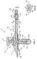
- FIG. 1 shows a cross-sectional view of a system described as general background to the invention as it would appear immediately prior to insertion through the skin.
- the medication injection port system 1 consists of five subassemblies, namely: the insertion needle assembly 5, the injection port assembly 10, the needle guard 30, the quick-release connector assembly 40 and the cap assembly 50 (shown in Figure 6).
- the needle assembly 5 consists of a solid core needle 6 having a proximal section 8 and a reduced diameter distal section 7 and a rigid plastic handle 9.
- the needle 6 could also be entirely or partially hollow and would typically be made from a stainless steel such as type 304.
- the diameter of the needle would typically be 0.45 mm except for the distal section 7 which would typically be 0.25 mm.
- the injection port assembly 10 consists of a one piece main body 11 having a tubular body extension 12, an inlet lumen 13A, a tubular lumen 13B and a soft, flexible cannula 14 having a side port 15. Although it is ideal to have the body extension 12 and the soft cannula 14 moulded into the main body 11, either one of these two parts may be formed separately and then bonded or adhesively joined into the main body 11.
- a removable needle guard 30 which is temporarily attached to the bottom surface 20 of the main body 11 protects the patient from being inadvertently stuck by the needle's sharp end prior to insertion through the skin.
- the needle guard 30 is shown with a thin, flexible flange 31 that has a tab 33 which extends beyond the perimeter of the flange 31 at one place on the flange's perimeter.
- a pressure sensitive adhesive coating 35 placed on the upper surface of the flange 31 holds onto the bottom surface 20 of the main body 11 until the tab 33 is used to pull the flange 31 and needle guard 30 away from the main body 11. It is also envisioned that the adhesive could be placed on the bottom surface 20 of the body 11 where it would adhere to the skin after the needle guard is removed.
- an antibiotic ointment either at site 32B if it is desired that the ointment only cover the insertion puncture wound after insertion,or at a position remote from the main body 11 in the region of the distal end of the cannula if it is also desired to lubricate and coat the exterior surface of the cannula as it is inserted through the subcutaneous tissue. It should be noted that there is a closed, air tight volume within the needle guard 30 that would prevent drying out of an antibiotic ointment prior to the needle guard's removal from the bottom surface of the main body 11.
- the shipping package which is used to sterilise and ship the injection port assembly could also have moulded into it a needle guard section which could also include an antibiotic ointment.
- a needle guard section which could also include an antibiotic ointment.
- the undersurface of the body 11 is provided with a groove (not shown) surrounding the cannula, so that as the needle and cannula are pushed through the skin, excess antibiotic collects in that groove rather than being squeezed out between the skin and the undersurface of the main body portion 11
- FIG. 1 Also shown in Figure 1 is a self-sealing, soft, elastomer septum 22 which seals the fluid lines after the needle 6 is pulled out.
- the septum 22 would typically be fabricated from a low durometer silicone rubber that has been placed in compression.
- Figure 2 shows the transverse cross-section of the tubular body extension 12 which encloses the lumen 13B.
- the connector housing 42 and quick-release actuator buttons 46 are shown in Figures 1 and 2.
- the tubular extension 12 terminates in a quick-release connector 40 which is also illustrated in Figure 5.
- Figures 1 and 5 show a soft elastomer seal 24 within the quick-release connector 40 which provides a fluid tight seal.
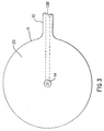
- the guard 30 Before insertion of the injection port system 1 into the skin, the guard 30 is removed. When this is accomplished, the view of the bottom of the injection port assembly 10 would be as shown in Figure 3. After the guard 30 is removed, the user would grip the needle assembly handle 9 and push it and the soft cannula 14 through the skin. When doing this, the exterior shoulder of the needle (where proximal section 8 joins distal section 7) cooperates with an interior shoulder in the cannula 14 to place most of the length of the cannula 14 in tension. This design prevents the soft, flexible cannula 14 from folding up like an accordion (i.e. buckling) when it is pushed through the skin.
- an accordion i.e. buckling
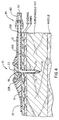
- Figure 4 shows the injection port assembly 10 with the needle assembly 5 removed and the soft cannula 14 in place with its distal end lying in the subcutaneous fat. Also shown in Figure 4 is the quick-release connector 40 whose female connector is joined to the distal end of the tubing 60 and whose proximal end is connected to a portable pump (not shown).
- a portable pump not shown.
- the end hole 19 could be replaced by a sharpened point and only the side hole(s) 15 could be used.
- the tubular body extension 12 could be formed from a separate piece of plastic and then joined with a fluid tight seal into the body 11. It should be noted that there is an absolutely no fluid chamber within the main body 11. This is a result of the bottom surface of the septum 22 being placed at the proximal end of the exit lumen 18. There are only the continuous lumens 13A, 13B and 18 through which the medication flows. Therefore there is not the disadvantage of having a fluid chamber dead space which increases the height of the main body and in which medication such as insulin could precipitate out as solid insulin.
- the lumens 13A and 13B are the connecting lumens between the quick-release connector assembly 40 and the exit lumen 18 in the soft cannula 14.
- FIG. 4 also shows an adhesive tape 29 which extends for approximately 6 mm beyond the outer perimeter of the main body 11. This tape would also follow the skin's changing shape.
- the FIG. 4 embodiment does not use an adhesive on the bottom surface of the main body 11, however such an adhesive could be used instead of or in combination with the adhesive tape 29 to hold the main body 11 against the patient's skin.
- FIG. 4 also shows a flat surface on the bottom of the main body 11. This is in contradistinction to the Yates invention which shows no flat surface at all and the Kanopka et al invention which requires a cylindrical segment extending below the bottom surface of a holding pad into which cylindrical segment the soft cannula is inserted. Although there may be some advantages to a cylindrical segment extending below the bottom surface of Kanopka's "holding pad", such a cylindrical segment protruding into the skin for several days can be uncomfortable for some patients.
- the flat surface at the bottom of the main body 11 should be more comfortable for long term use for most patients.
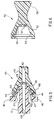
- FIG. 5 shows a view of the quick-release connector assembly 40 which is orthogonal to the views shown in FIGS. 1 and 4.
- the tubular extension 12 has at its proximal end a tapered male portion in the form of a flat top pyramid with two broad sides and two narrow sides. The broad sides lie generally parallel to the skin while the two narrow sides are perpendicular to the skin surface. This is also true for the tubular extension 12 whose broad surfaces lie parallel to the skin and whose narrow surfaces lie perpendicular to the skin.
- This geometry makes it easy for the patient to bend the tubular extension upward away from the skin in order to easily squeeze the actuator buttons 46 of the quick-release connector 40.
- This geometry also places the quick-release actuator buttons 46 in an orientation where they cannot be inadvertently released by pushing down on the skin at the site of the quick-release connector. It should be understood that a cylindrical tubular extension would also be satisfactory.
- the male portion has a taper 41A which mates with the taper 41B of the female portion of the quick-release connector 40.
- Each actuator button 46 is mounted on a flexure 47 which also has the male detent 43 mounted on its exterior surface.
- the quick-release connector 40 has its two portions firmly joined together with the circular ridge 49 making a fluid tight juncture with the elastomer washer 24.
- the index finger and thumb are placed on and squeezed together onto the actuator buttons 46, the quick-release connector 40 can be easily separated by pulling outward on the tubing 60.
- the tubular extension 12 and the tubing 60 are pushed together until the detents 43 and 44 are joined. If the male and female portions of the quick-release connector 40 are rotated by 180 degrees, the male detents 43 will still snap into the female detents 44. Thus, the patient need not be aware of the angular orientation of the tubular extension 12 relative to the tubing 60 other than the fact that the broad sides of the male and female portions must be aligned.
- a Luer lock fitting especially a miniature version as shown in FIG. 7, could accomplish the same function as the quick-release connector 40.
- a sterilized disposable female cap 50 shown in FIG. 6 can be placed over the male portion.
- the female detents 54 would then mate with the male detents 43, and the circular ridge 49 would seal against the soft elastomer seal 57.
- the handle 58 on the cap 50 makes for easy assembly with the male portion of the quick-release connector 40.
- a properly configured male plug (not shown) could be used to close off the female portion of the quick-release connector 40 when the male and female portions are separated.
- the cap 50 would be used to maintain sterility when showering, swimming or performing any other activity which would be enhanced by disconnecting the tubing 60 and the portable medication pump from the main body assembly 10. To reconnect the pump, the female cap 50 is removed and the quick-release connector 40 is reconnected.
- the main body 11 and needle handle 9 would typically be molded from Teflon, Surlyn, polyurethane or any similar plastic which is readily formed by injection molding.
- the tubing 60 could be formed with an interior cylinder (not shown) of polyolefin or a similar plastic and an outer tubing (not shown) of PVC or a similar plastic. It is important that all surfaces in contact with the medication do not degrade that medication.
- the lengths of the needle 6 (including the distal portion 7) and the cannula 14 can be varied in order to accommodate individuals with different thicknesses of subcutaneous fat.
- a soft cannula length of 8.5 mm below the bottom surface 20 of the main body 11 could be used for most individuals.
- an increased length of soft cannula could be used for individuals with a thicker fat layer, or for suprapubic or intravenous use.
- the length of the cannula 221 will be in the range between 0.2 and 0.85cms.
- tie cannula 14 It is also envisioned to coat the exterior surface of tie cannula 14 with a lubricity coating to aid in its insertion through the skin.
- the medication injection port system 100 consists of four subassemblies, namely: the needle guard 51, the insertion needle assembly 80, the injection port assembly 70 and the mini-Luer-lock connector assembly 90.
- the needle assembly 80 consists of a hollow tube proximal section 86 and a reduced diameter solid needle distal section 88. A proximal portion of the proximal section 86 is fixedly attached to a comparatively rigid plastic handle 82.
- the tube 86 has an inlet port 84 which allows the passage of fluid from the inlet lumen 13A into the lumen 85 of the tube 86.
- Fluid entering the lumen 85 will flow out of the top opening of the needle's proximal section 86.
- Both the hollow and the solid sections of the needle would typically be made from a stainless steel such as type 304.
- the outside diameter of the proximal section 86 would typically be 0.45 mm and the diameter of the distal section 88 would typically be 0.25 mm.
- the injection port assembly 70 consists of a one piece main body 11 having a (typically) flat tubular body extension 12 with a lumen 13B which is in fluid communication with the inlet lumen 13A and the exit lumen of the soft cannula 14 having a side port 15.
- a body extension 12 and the soft cannula 14 molded into the main body 11 either one of these two parts may be formed separately and then bonded or adhesively joined into the main body 11.
- a removable needle guard 51 which fits into a groove 16 of the main body 11 protects the patient from being inadvertently stuck by the needle's sharp end prior to insertion through the skin.
- an antibiotic ointment either at site 53B if it is desired that the ointment only cover tie insertion puncture wound after insertion, or the ointment can be placed at position 53A if it is also desired to lubricate and coat the exterior surface of the cannula as it is inserted through the subcutaneous tissue.
- a self-sealing, soft, elastomer septum 22 which seals the fluid lines after the insertion needle assembly 80 is pulled out.
- the septum 22 would typically be fabricated from a low durometer silicone rubber that has been placed in compression
- a bacterial filter 78 is placed in the fluid path within the injection port 70 to prevent the delivery of bacteria into the subcutaneous tissue. Such a bacterial filter 78 is shown as part of the mini-Luer lock fitting 72 attached to the injection port 70.
- a filter support disk 74 provides structural support for the bacterial filter 78 while allowing free passage of fluid into the lumen 13B.
- the mini-Luer lock connector assembly 90 consists of a male miniature Luer lock fitting containing a soft, self-sealing elastomer injection septum 92 through which hypodermic needles can be inserted to inject medication from a syringe.
- a needle stop 94 with holes too small in diameter for a needle to penetrate prevents the hypodermic needle from damaging the bacterial filter 78. Because of the needle stop 94, fluid from a hypodermic needle syringe will be injected into the lumen 96, pass through the needle stop 94 then through the bacterial filter 78 into the main body of the injection port 70.
- the injection septum 92 would typically be fabricated from a low durometer silicone rubber that has been placed in compression.
- the connector assembly 90 would typically be located between 5 and 10 cm from the needle assembly 80; and would always be less than 25 cm away. Most typically, the connector 90 would be located at a position from the edge of the main body 11 within a distance that is less than the diameter of the main body 11.
- FIG. 7 shows an injection septum 92 at the end of the mini-Luer lock assembly 90, it is understood that, as in FIG. 1, this connector could instead attach to a length of flexible tubing for connection to an external, portable medication pump.
- the medication injection port system 110 consists of four subassemblies, namely: the insertion needle assembly 80, the needle guard 114, the injection port assembly 120 and the mini-Luer-lock connector assembly 130.
- the needle assembly 80 consists of a hollow tube 86 having a reduced diameter solid needle 88 inserted into its distal end and a comparatively rigid plastic handle 82.
- the tube 86 has an inlet port 84 which allows the passage of fluid from the lumen 113 into the lumen 85 of the tube 86. Fluid entering the lumen 85 will flow out of the top of the tube 86.
- the tube 86 and solid needle 88 would typically be made from a stainless steel such as type 304.
- the outer diameter of the tube 86 would typically be 0.45 mm and the diameter of the needle 88 would typically be 0.25 cm.
- the injection port assembly 120 consists of a one piece main body 111 having a flat tubular body extension 115 with a lumen 113 and a soft, flexible cannula 14 having a side port 15. Although it is ideal to have the body extension 115 and the soft cannula 14 molded into the main body 111, this and other embodiments envision either one of these two parts to be formed separately and then bonded or adhesively joined into the main body 111.
- a removable needle guard 114 which fits into a groove 116 of the main body 111 protects the patient from being inadvertently stuck by the needle's sharp end prior to insertion through the skin. Also shown in FIG.
- a self-sealing, soft, elastomer septum 122 which is placed in compression by a septum cap 123.
- the septum 122 seals the fluid lines after the insertion needle assembly 80 is pulled out.
- the septum 122 would typically be fabricated from a low durometer silicone rubber that has been placed in compression.
- Above the septum 122 is an injection hole 124 in the septum cap 123.
- a bacterial filter 128 is placed in the fluid path between the injection chamber 126 and the exit lumen of the soft cannula 14 through which medication is delivered into the patient.
- a filter support disk 129 provides structural support for the bacterial filter 128 while allowing free passage of fluid into the exit lumen of the soft cannula 14.
- a check valve 121 is located between the mini-Luer lock connector 125 and the injection chamber 126.
- medication delivered by a hypodermic syringe through the septum 122 into the injection chamber 126 will flow through the bacterial filter 128 into the connecting lumen 118, through the exit lumen in the soft cannula 14 and into the patient's body because the check valve 121 prevents flow out through the lumen 134.
- the mini-Luer lock connector assembly 130 consists of a male miniature Luer lock fitting 131 which connects to a length of flexible tubing 132 with lumen 134 which would connect to an external fluid pumping device. Medication from a pump would flow through the lumen 134 in the flexible tube 132, through the check valve 121 into the lumen 113 in the flat tubular body extension 115 of the one piece main body 111, then through the injection chamber 126 through the bacterial filter 128, filter support disk 129, and lumen 118 into the exit lumen of the soft cannula 14 and then into the patient's body.
- the medication injection port system 150 consists of three subassemblies, namely the insertion needle assembly 80, the needle guard 114 and the injection port assembly 160.
- the needle assembly 80 consists of a hollow tube 86 having a reduced diameter solid needle 88 inserted into its distal end and a plastic handle 82.
- the tube 86 has an inlet port 84 which allows the passage of fluid from the lumen 126 into the lumen 85 of the tube 86. Fluid entering the lumen 85 will flow out of the top exit port of the tube 86. This allows the fluid passageways in the injection port system 150 to be flushed or primed.
- the injection port assembly 160 consists of a one piece main body 151 having a soil, flexible cannula 14 which has two side ports 15. Although it is ideal to have the soft cannula 14 molded into the main body 151, either one of these two parts may be molded separately and then bonded or adhesively joined into the main body 151.
- a removable needle guard 114 which fits into a groove 116 of the main body 151 protects the patient from being inadvertently stuck by the needle's sharp end prior to insertion through the skin.
- a self-sealing, soft, elastomer septum 122 which is placed in compression by a septum cap 123.
- the septum 122 seals the fluid lines and chambers after the insertion needle assembly 80 is pulled out.
- the septum 122 would typically be fabricated from a low durometer silicone rubber that has been placed in compression.
- Above the septum 122 is an injection hole 124 in the septum cap 123.
- a bacterial filter 128 to prevent the delivery of bacteria into the patient's body is placed in the fluid path within the injection port 160 between the injection chamber 126 and the exit lumen of the soft cannula 14 which delivers medication to the patient
- a filter support disk 129 provides structural support for the bacterial filter 128 while allowing free passage of fluid into the exit lumen of the soft cannula 14.
- FIG. 7, 8 and 9 show vertically oriented, disk-shaped bacterial filters, it is understood that the shape of the filter might be cylindrical, or rectangular and the orientation could be at any angle.
- FIGS. 1, 4, 7, 8 and 9 show a flexible cannula 14 which is generally perpendicular to the bottom surface 17 of the main body, it should be understood that there could be conditions which would require the cannula 14 to be inclined at an angle between 20 and 80 degrees relative to the bottom surface 17. Such angles could be advantageous for intravenous insertion of the cannula 14.
- FIG. 8 shows a check valve 121 to prevent flow out of the mini-Luer lock connector 130 during hypodermic injection, it is clear that alternate means for preventing such-flow such as a closed mini-Luer cap could be used to prevent such flow.
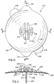
- FIGS. 10, 11 and 12 illustrate an injection port assembly 200 according to a first embodiment of the invention which consists of three sub-assemblies, namely: a main body 210, a cannula section 220 and an adhesive 230.
- the main body 210 and the cannula section 221 may be formed together as a one-piece plastic molding.
- the main body 210 is generally in the form of a flat, circular disk.
- Two projections 201 are aligned in the direction of the guide ridges 202.
- the interior surface 203 of the guide ridges 202 are used to help guide the plastic needles 245 (shown in FIGS.
- the projections 201 aid the patient in aligning the injection port assembly 200 in generally horizontal direction when adhesively attaching it to the skin in the abdominal region.
- the ridges 202 are in a horizontal position, it is somewhat easier for the patient to slide the plastic needle 245 into its proper place inside the ridges 202 and into the slit 204.
- the cannula section 220 is best shown in FIGS. 11 and 12.
- the cannula section 220 consists of a flexible cannula 221 having a tapered entry section 222 located within a central section 223 that forms a pressure tight seal with the main body 210 just beneath, or adjacent to and below, the septum 205.
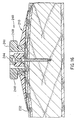
- An outer section 224 includes a lip 225 which is designed to engage a mating projection or lip 247 of a three-pronged connector 241 as shown in FIGS. 15 and 16.
- the cannula section 220 also includes two tapered entry holes 226 which guide tapered locking pins 246 of the three-pronged connector 241 into the cannula section 220, as shown in FIGS. 15 and 16
- Adhesive assembly 230 consists of a two-sided adhesive sheet 232 which is joined on its inner surface to the underside of the main body 210, and on its outer side to two removable plastic sheets 234 which are separated by a diagonal cut 238 as shown by the dotted line in FIG. 10.
- tabs 236, which are part of the plastic sheets 234 are pulled away from the bottom surface of the main body 210, the outer adhesive surface of the adhesive sheet 232 is exposed and the injection port 200 can then be adhesively joined to the patient's skin,
- the projections 201 of the main body 210 are useful in pulling the injection port 200 off the skin.
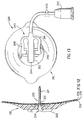
- FIGS. 13 and 14 illustrate a connector and tubing assembly 240 of which the three-pronged connector 241 is a part.
- the three-pronged connector 241 is mounted onto the main body 210 of the injection port 200.
- the assembly 240 consists of the connector 241 which is joined to a fluid connector 242 by means of tubing 243.
- the fluid connector 242 is typically a female Luer connector that is adapted to join to an external source of medication such as a portable insulin pump (not shown).
- the three-pronged connector 241 as illustrated in FIGS 13, 14, 15 and 16 has a central prong 244 that is used to help guide the plastic needle 245 into the slit 204 of the septum 205 of the main body 210.
- the connector 241 is also guided into the tapered entry holes 226 of the main body 210 by means of taped locking pins 246 located on the outer two prongs of the three pronged connector 241.
- a downward finger pressure can be used to push the locking pins 246 into the tapered entry holes 226 as shown in FIGS. 15 and 16.
- the lip 225 of the cannula section 220 is locked onto the mating lip 247 of the locking pins 246.
- the patient uses his thumb and forefinger to squeeze together outer surfaces 248 of the outer prongs of the connector 241.
- the lips 225 and 247 disengage, and the connector 241 can be pulled out of the cannula section 220.
- the plastic needle 245 will not touch the table surface.
- the flat upper surface of the septum 205 can be wiped with an alcohol swab before reinserting the plastic needle 245, thus assuring a sterile connection of the three-pronged connector 241 and precluding the need for a special sterility maintaining cover to be placed over the septum 205 when the connector 241 is removed from the cannula section 220.
- the priming can be accomplished by attaching the connector 242 to a source of medication and pumping the medication through the tubing 243 and then out of a central lumen 249 of the plastic needle 245.
- the connector 241 can then be joined into the cannula section 220.
- FIG. 17 illustrates a needle assembly 250 that is used to subcutaneously place the cannula 221 of the injection port 200.
- the needle assembly 250 consists of pointed needle 251 placed inside the cannula 221.
- the needle 251 is joined at its proximal end to a hollow handle 252.
- the shape of the proximal end 253 of the needle handle 252 as shown in FIG. 17 is such as to secure placement of a finger tip when pushing the needle 251 and cannula 221 through the skin.
- the main body 210 is pushed firmly against the skin thus effecting a good adhesive connection of the injection part 200 onto the skin.
- the needle assembly 250 is then removed and the connector 241 is inserted into the cannula section 220 as illustrated in FIGS. 13, 14, 15 and 16.
- the material of the main body 210 would be a low durometer elastomer such as silicone rubber, polyurethane or polyethylene.
- the cannula section would be molded from a similar elastomer material but of a considerably higher durometer.
- the connectors 241 and 242 and the needle handle 252 would be molded from a hard plastic such as polycarbonate.
- the main body 210 would be between 2 and 5 cm in diameter with all other dimensions being approximately as scaled from the drawings of FIGS. 10 to 17 inclusive.
- FIGS. 18 and 19 show a needle assembly 260 for use in conjunction with the injection port assembly 200 of FIGS. 1 to 8.
- the needle assembly 260 is designed to avoid inadvertent needle sticks by the patient or health care worker who place the injection port assembly 200 onto the patient.
- the needle assembly 260 consists of a housing 261, slideable needle 262 and a compressional coil spring 263.
- the housing 261 consists of a body 265, a plastic needle 267, a distil end section 269 and a bushing 271.
- the slideable needle 262 consists of a shaft 264, a needle stop 266, a metal needle 268 and a finger push button 270.
- patient receives the injection port assembly 200 with the plastic needle 267 placed into the septum of the main body of the injection port and with the distal end section 269 in contact with the top of the main body.
- the spring 263 normally urges the slidable needle 262 to be in the position shown in Figure 18.
- the patient would then hold the body 265 between his thumb and middle finger and use his index finger to apply a force to the finger push button 270 thus causing the slidable needle 262 to assume the position shown in Figure 19.
- the needle 268 (which would be located within a flexible cannula) would be used to place the distal end of the flexible cannula through the skin and into the subcutaneous fat.
- the injection port assembly would then adhere to the skin, the needle assembly 260 would be pulled out, and the slidable needle 262 would automatically be placed into the position shown in Figure 18.
- the sharpened point of the needle 268 would be shielded by the housing 261 thereby precluding inadvertent needle sticks.
- the needle assembly 260 would then be disposed of in the safe, needle retracted position shown in Figure 18.
- safety needle assembly could be used for placement of the needle in the injection port assembly, the common feature of such needle assemblies being that the sharpened needle point is retracted into a plastics needle housing.
Abstract
Description
- This invention relates to devices for the subcutaneous delivery of medication, more especially subcutaneous injection ports which are inserted through the skin, and which may remain in place for several days for the periodic or continuous administration of medication.
- Currently a major application of such injection ports is to provide chronic delivery of medication such as insulin from portable pumps. When used with a pump, a fluid line is required to connect the injection port to the portable pump. Another application of a subcutaneous injection port is to permit multiple injections without the need to repuncture the skin. In this application, medication is injected from a standard hypodermic syringe and needle through a soft elastomer septum into the injection port which delivers the medication subcutaneously.
- If a hollow metal needle is left in place through the skin to provide medication delivery, after one or two days the needle becomes uncomfortable to the patient. A more comfortable disposable injection port is described in U.S Patent No. 3,547,119 by Hall et al which has a soft, thin-walled cannula which is subcutaneously inserted over a metal needle. After insertion, the metal needle is removed leaving only the soft cannula through the skin. However the Hall device has several limitations, namely:
- (1) it is designed for infusion into the bladder and not for subcutaneous injection;
- (2) the soft, thin-walled cannula which is subcutaneously inserted over the metal needle is placed in compression during insertion which can result in buckling of the cannula;
- (3) the device has an extremely high profile making it impractical for ambulatory use where it is highly desirable to be hidden under clothing; and
- (4) it does not provide a bacterial filter.
-
- More recently, a soft cannula subcutaneous injection set described in U.S. Patent No. 4,755,173 by Kanopka et al has become available. While being lower in profile than the Hall device and specifically designed for subcutaneous delivery of medication, the Kanopka device also has several shortcomings, namely:
- (1) there is no method for disconnecting the tubing near the point of subcutaneous insertion thus requiring a long length of tubing to remain connected while showering, exercising or performing other activities for which having a long length of tubing is disadvantageous;
- (2) many separate parts are required to construct the injection set which increases costs and the probability of leakage;
- (3) like the Hall device, the soft, thin-walled cannula which is subcutaneously inserted over a hollow needle is placed in compression during insertion which can result in buckling of the cannula;
- (4) the multiple parts design results in a comparatively high outward protrusion from the skin;
- (5) there is a fluid chamber within the device which is a dead space for medication; and
- (6) the cylindrical segment of the catheter hub which extends below the holding pad presses on the skin and often becomes uncomfortable for the patient.
-
- Another soft cannula subcutaneous injection port is described in U.S. patent 4,531,937 by Yates. The Yates device, however, has several disadvantages, namely:
- (1) it requires a fluid trapping capability in the needle hub for the expulsion of air from the inside of the device;
- (2) like the devices of Hall and Kanopka, the soft, thin-walled cannula which is subcutaneously inserted over a hollow needle is placed in compression during insertion which can result in buckling of the cannula;
- (3) it has a "stepped bore" diameter which forms a fluid chamber within the device which is a dead space for medication;
- (4) it does not provide a bacterial filter; and
- (5) it lacks a flat surface for attachment to the skin to prevent bending of the soft cannula during prolonged insertion.
-
- Still another soft cannula injection port is described in U.S. patent 4,311,137 by Gerard. The Gerard device, however, has several disadvantages, namely:
- (1) it requires a complex movable needle/septum assembly with one position for flushing and a second position for insertion;
- (2) it has a lumen (referred to as a passage) which forms a fluid chamber within the device which is a dead space for medication;
- (3) it does not provide a bacterial filter;
- (4) the Gerard design results in a comparatively high outward protrusion from the skin; and
- (5) like the devices of Hall, Kanopka, and Yates, the soft, thin-walled cannula which is subcutaneously inserted over a hollow needle is placed in compression during insertion which can result in buckling of the cannula.
-
- European Patent Application EP-A-0239244 discloses a subcutaneous injection set having a main body with an adhesive lower surface, a fluid chamber mounted above the main body and an inlet through which fluid may be supplied. In common with other devices, this device is disadvantageous as:
- (a) it has a dead area in which medication can collect;
- (b) it does not provide a bacterial filter;
- (c) it has no means for easily disconnecting the device from a medicament supply; and
- (d) it has a large raised profile above the surface of the skin.
-
- According to the invention there is provided a device for delivery of medication from an external source through a patient's skin, the device comprising an injection port assembly having top and bottom surfaces, a main body, a cannula section and an adhesive section, the cannula section having an elongate cannula with a central lumen that protrudes in a generally downward direction from the injection port assembly, the lumen having proximal and distal ends, characterised in that the lumen's proximal end is situated adjacent to and below a septum arranged in the main body, the cannula section further including two holes, the holes including respective engaging means for attachment to a fluid connector engaging means. The septum is preferably formed integral with the main body and at its centre.
- It is therefore possible to provide a subcutaneous injection and medicament delivery system which facilitates the placement of a flexible cannula in the subcutaneous tissue, which improves patient comfort and convenience, and which is suitable for the periodic or long term delivery of a medicament subcutaneously to a patient.
- A system according to an embodiment of the invention has a generally flat, moulded plastics body portion having a generally planar undersurface which is shaped to engage against the surface of the skin in surrounding relationship to the site of delivery of the medicament to the patient. A flexible cannula projects downwardly from the underside of the moulded body portion, the cannula having a central lumen which communicates with a passageway formed in said body for the throughflow of medicament from an inlet port in the moulded body to the cannula, and through the lumen of the cannula to a delivery port formed in the distal end of the cannula. A stylet needle is removably insertable into the cannula through the moulded body, the needle having a length greater than that of the cannula so that, when inserted therein, the tip of the needle projects beyond the distal end of the cannula. The needle has adjacent to its tip an outwardly projecting shoulder which, when the needle is inserted into the flexible cannula, engages against an inwardly projecting shoulder formed in the lumen of the cannula adjacent its distal end, so that engagement of the needle into the cannula serves to tension the flexible cannula and prevent the cannula from buckling as the needle and cannula are pushed through the patient's skin, the needle thereafter being withdrawn to leave the cannula in place and with the undersurface of the moulded body portion lying against the patient's skin.
- The subcutaneous injection port may include a quick-release connector, typically to be placed 5 to 10 cm from the device's main body. Alternatively, the quick-release connector may be placed directly onto the main body. Thus the soft cannula could remain in place through the skin while virtually all of the 100 plus cm of tubing typically connected to the portable pump could be temporarily detached and placed on a clean surface. When the main tubing is detached, a disposable sterilised cap can be placed over the quick-release connector to keep it sterile while showering, exercising or performing any other activity for which it is desirable to remove the long length of tubing. Furthermore, the connector can have a hard plastic needle which can penetrate through a previously slit septum on the injection port to provide a fluid path from an external portable pump, through the injection port and subcutaneously into the patient.
- An in-line bacterial filter may be incorporated into the subcutaneous injection port so that when the connecting tubing is removed, a cap is not needed to prevent bacteria from entering the injection port. Such an in-line bacterial filter will, when dry, allow venting of air from the device and when wet (after priming) prohibit air bubbles from passing into the body. This is of particular importance for intravenous use.
- A soft elastomer septum may be provided for hypodermic needle injection of medication. This septum may be directly incorporated into the main body of the injection port or it can be contained in a quick-release connector which mates with the quick-release connector on the injection port.
- The injection port can be realised in a one piece main body design. The one piece design reduces costs and further reduces the probability of a fluid leakage. The one piece design and the absence of a fluid chamber decreases the height of the device above the skin resulting in a desirable low profile which is more easily hidden under clothing. The injection port may also be designed to allow the placement of its soft cannula at angles between 20 and 80 degrees relative to the bottom surface of the main body of the injection port which could be advantageous for intravenous insertion.
- The injection port may also be provided with a needle guard which is to be removed prior to placing the needle and cannula through the skin and which can contain a broad spectrum antibiotic substance such as an antibiotic ointment. Thus, when the needle guard is removed, some ointment remains on the needle which ointment can decrease infections at the insertion site and also can act as a lubricant for the exterior surface of the cannula.
- The cannula can be made with a side port which can allow continued delivery of medication even if the end port becomes blocked. Also, the side port allows for more diffuse infusion of the medication so that it would be taken up more quickly into the body.
- The main body of the injection port may have a concave upper surface to provide a flexible edge at the outside diameter of the main body. This is more comfortable for the patient because the flexible edge will more readily adapt to the changing shape of the skin surface.
- These and other important features of this invention in all its various independent aspects, as defined in the claims, will become apparent from the following detailed description of the invention made with reference to the accompanying drawings in which
- Figure 1 is a longitudinal cross section of a device shown in its form prior to insertion through the skin.
- Figure 2 is a transverse cross section of the device at section 2-2 of Figure 1.
- Figure 3 shows the bottom of the device with the needle guard removed.
- Figure 4 is a longitudinal cross section of the injection port and body tubular extension showing how the soft, flexible cannula is subcutaneously inserted into the subcutaneous fat.
- FIG. 5 shows an enlarged cross section of the quick-release connector at section 5-5 of FIG. 1.
- FIG. 6 shows an end cap.
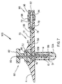
- FIG. 7 is a longitudinal cross section of another device shown in its form prior to insertion through the skin which device shows a bacterial filter, a mini-Luer lock fitting for quick-release, a hollow upper tube insertion needle and a soil elastomer septum at the proximal end of the quick-release fitting for hypodermic injection of medication via the device.
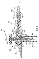
- FIG. 8 is a longitudinal cross section of still another device shown in its form prior to insertion through the skin. This device contains a bacterial filter, and both a means for hypodermic injection as well as delivery of medication from an external, portable pump.
- FIG. 9 is a longitudinal cross section of yet another embodiment of the device shown in its form prior to insertion through the skin. This device contains a bacterial filter, and only a means for hypodermic injection of medication.
- FIG. 10 is a top view of an injection port assembly according to a first embodiment of the invention;
- FIG. 11 is a cross section at 11-11 of the injection port assembly shown in FIG. 10.
- FIG. 12 is a cross section at 12-12 of the injection port assembly shown in FIG. 10.
- FIG. 13 is a top plan view showing a three-pronged connected mounted at the center of the injection port assembly of FIG. 10;
- FIG. 14 is a side view of the connector and injection port assembly according to the first embodiment of the invention;
- FIG. 15 is a cross section of the three-pronged connector and the injection port assembly of the first embodiment showing the needle assembly removed and the three-pronged connector above the top surface of the injection port assembly;
- FIG. 16 is a cross section of the three-pronged connector shown attached to the injection port assembly of the first embodiment;
- FIG. 17 is a cross section of a needle assembly and the injection port assembly of the first embodiment showing the needle assembly as it is used to place the cannula through the skin and into the subcutaneous fat;
- FIG. 18 is a cross section of a further needle assembly, that automatically shields the needle point with the needle, shown in its retracted position; and
- FIG. 19 is a cross section of the needle assembly of FIG. 18 in its extended position for inserting the injection port cannula through the skin.
-
- The systems shown in Figures 1 to 9 and the needle assemblies shown in Figures 18 and 19 are not embodiments of the invention but constitute general background included to assist understanding of the invention and its embodiments. It will be appreciated that individual features of the systems of Figures 1 to 9 and needle assemblies of Figures 18 and 19 may be incorporated into one or more of the systems according to Figures 10 to 17, for example in respect of the removable needle guard, the needle and the bacterial filter, as well as the general teachings relating to cannula lengths.
- Referring now to the drawings, Figure 1 shows a cross-sectional view of a system described as general background to the invention as it would appear immediately prior to insertion through the skin. The medication injection port system 1 consists of five subassemblies, namely: the
insertion needle assembly 5, theinjection port assembly 10, theneedle guard 30, the quick-release connector assembly 40 and the cap assembly 50 (shown in Figure 6). Theneedle assembly 5 consists of a solid core needle 6 having aproximal section 8 and a reduced diameter distal section 7 and a rigidplastic handle 9. The needle 6 could also be entirely or partially hollow and would typically be made from a stainless steel such as type 304. The diameter of the needle would typically be 0.45 mm except for the distal section 7 which would typically be 0.25 mm. - The
injection port assembly 10 consists of a one piecemain body 11 having atubular body extension 12, aninlet lumen 13A, atubular lumen 13B and a soft,flexible cannula 14 having aside port 15. Although it is ideal to have thebody extension 12 and thesoft cannula 14 moulded into themain body 11, either one of these two parts may be formed separately and then bonded or adhesively joined into themain body 11. Aremovable needle guard 30 which is temporarily attached to thebottom surface 20 of themain body 11 protects the patient from being inadvertently stuck by the needle's sharp end prior to insertion through the skin. Theneedle guard 30 is shown with a thin,flexible flange 31 that has atab 33 which extends beyond the perimeter of theflange 31 at one place on the flange's perimeter. A pressure sensitiveadhesive coating 35 placed on the upper surface of theflange 31 holds onto thebottom surface 20 of themain body 11 until thetab 33 is used to pull theflange 31 andneedle guard 30 away from themain body 11. It is also envisioned that the adhesive could be placed on thebottom surface 20 of thebody 11 where it would adhere to the skin after the needle guard is removed. - Within the
needle guard 30 there can be placed an antibiotic ointment either atsite 32B if it is desired that the ointment only cover the insertion puncture wound after insertion,or at a position remote from themain body 11 in the region of the distal end of the cannula if it is also desired to lubricate and coat the exterior surface of the cannula as it is inserted through the subcutaneous tissue. It should be noted that there is a closed, air tight volume within theneedle guard 30 that would prevent drying out of an antibiotic ointment prior to the needle guard's removal from the bottom surface of themain body 11. It should also be noted that the shipping package which is used to sterilise and ship the injection port assembly could also have moulded into it a needle guard section which could also include an antibiotic ointment. Preferably the undersurface of thebody 11 is provided with a groove (not shown) surrounding the cannula, so that as the needle and cannula are pushed through the skin, excess antibiotic collects in that groove rather than being squeezed out between the skin and the undersurface of themain body portion 11 - Also shown in Figure 1 is a self-sealing, soft,
elastomer septum 22 which seals the fluid lines after the needle 6 is pulled out. Theseptum 22 would typically be fabricated from a low durometer silicone rubber that has been placed in compression. - Figure 2 shows the transverse cross-section of the
tubular body extension 12 which encloses thelumen 13B. Theconnector housing 42 and quick-release actuator buttons 46 are shown in Figures 1 and 2. Thetubular extension 12 terminates in a quick-release connector 40 which is also illustrated in Figure 5. Figures 1 and 5 show asoft elastomer seal 24 within the quick-release connector 40 which provides a fluid tight seal. - Before insertion of the injection port system 1 into the skin, the
guard 30 is removed. When this is accomplished, the view of the bottom of theinjection port assembly 10 would be as shown in Figure 3. After theguard 30 is removed, the user would grip the needle assembly handle 9 and push it and thesoft cannula 14 through the skin. When doing this, the exterior shoulder of the needle (whereproximal section 8 joins distal section 7) cooperates with an interior shoulder in thecannula 14 to place most of the length of thecannula 14 in tension. This design prevents the soft,flexible cannula 14 from folding up like an accordion (i.e. buckling) when it is pushed through the skin. - Figure 4 shows the
injection port assembly 10 with theneedle assembly 5 removed and thesoft cannula 14 in place with its distal end lying in the subcutaneous fat. Also shown in Figure 4 is the quick-release connector 40 whose female connector is joined to the distal end of thetubing 60 and whose proximal end is connected to a portable pump (not shown). Thus the liquid medication coming out of the pump first passes through thelumen 62 of thetubing 60, then thelumen 13B of thetubular body extension 12, then through theinlet lumen 13A of themain body 11, then through theexit lumen 18 of theflexible cannula 14 and finally out theend hole 19 of thecannula 14 and/or through the cannula'sside port 15. It should be understood that theside port 15 could be omitted. Conversely, theend hole 19 could be replaced by a sharpened point and only the side hole(s) 15 could be used. Also, thetubular body extension 12 could be formed from a separate piece of plastic and then joined with a fluid tight seal into thebody 11. It should be noted that there is an absolutely no fluid chamber within themain body 11. This is a result of the bottom surface of theseptum 22 being placed at the proximal end of theexit lumen 18. There are only thecontinuous lumens lumens release connector assembly 40 and theexit lumen 18 in thesoft cannula 14. - It should be noted that the upper surface of the
main body 14 is concave. This shape maximizes the flexibility of the outer perimeter of themain body 11. This provides for more patient comfort because where the main body perimeter joins onto the skin, it will more readily follow a changing shape of the skin surface. FIG. 4 also shows anadhesive tape 29 which extends for approximately 6 mm beyond the outer perimeter of themain body 11. This tape would also follow the skin's changing shape. The FIG. 4 embodiment does not use an adhesive on the bottom surface of themain body 11, however such an adhesive could be used instead of or in combination with theadhesive tape 29 to hold themain body 11 against the patient's skin. - FIG. 4 also shows a flat surface on the bottom of the
main body 11. This is in contradistinction to the Yates invention which shows no flat surface at all and the Kanopka et al invention which requires a cylindrical segment extending below the bottom surface of a holding pad into which cylindrical segment the soft cannula is inserted. Although there may be some advantages to a cylindrical segment extending below the bottom surface of Kanopka's "holding pad", such a cylindrical segment protruding into the skin for several days can be uncomfortable for some patients. The flat surface at the bottom of themain body 11 should be more comfortable for long term use for most patients. - FIG. 5 shows a view of the quick-
release connector assembly 40 which is orthogonal to the views shown in FIGS. 1 and 4. Thetubular extension 12 has at its proximal end a tapered male portion in the form of a flat top pyramid with two broad sides and two narrow sides. The broad sides lie generally parallel to the skin while the two narrow sides are perpendicular to the skin surface. This is also true for thetubular extension 12 whose broad surfaces lie parallel to the skin and whose narrow surfaces lie perpendicular to the skin. This geometry makes it easy for the patient to bend the tubular extension upward away from the skin in order to easily squeeze theactuator buttons 46 of the quick-release connector 40. This geometry also places the quick-release actuator buttons 46 in an orientation where they cannot be inadvertently released by pushing down on the skin at the site of the quick-release connector. It should be understood that a cylindrical tubular extension would also be satisfactory. - Returning now to FIG. 5 we see that the male portion has a
taper 41A which mates with thetaper 41B of the female portion of the quick-release connector 40. Eachactuator button 46 is mounted on aflexure 47 which also has themale detent 43 mounted on its exterior surface. When thefemale detent 44 is mated with themale detent 43, the quick-release connector 40 has its two portions firmly joined together with thecircular ridge 49 making a fluid tight juncture with theelastomer washer 24. When the index finger and thumb are placed on and squeezed together onto theactuator buttons 46, the quick-release connector 40 can be easily separated by pulling outward on thetubing 60. For reconnection, thetubular extension 12 and thetubing 60 are pushed together until thedetents release connector 40 are rotated by 180 degrees, themale detents 43 will still snap into thefemale detents 44. Thus, the patient need not be aware of the angular orientation of thetubular extension 12 relative to thetubing 60 other than the fact that the broad sides of the male and female portions must be aligned. Alternatively, a Luer lock fitting, especially a miniature version as shown in FIG. 7, could accomplish the same function as the quick-release connector 40. - When the female portion of the
connector 40 and thetubing 60 are disconnected from the male portion, a sterilized disposablefemale cap 50 shown in FIG. 6 can be placed over the male portion. Thefemale detents 54 would then mate with themale detents 43, and thecircular ridge 49 would seal against thesoft elastomer seal 57. Thehandle 58 on thecap 50 makes for easy assembly with the male portion of the quick-release connector 40. If desired, a properly configured male plug (not shown) could be used to close off the female portion of the quick-release connector 40 when the male and female portions are separated. It should be understood that thecap 50 would be used to maintain sterility when showering, swimming or performing any other activity which would be enhanced by disconnecting thetubing 60 and the portable medication pump from themain body assembly 10. To reconnect the pump, thefemale cap 50 is removed and the quick-release connector 40 is reconnected. - The
main body 11 and needle handle 9 would typically be molded from Teflon, Surlyn, polyurethane or any similar plastic which is readily formed by injection molding. Thetubing 60 could be formed with an interior cylinder (not shown) of polyolefin or a similar plastic and an outer tubing (not shown) of PVC or a similar plastic. It is important that all surfaces in contact with the medication do not degrade that medication. - It should also be noted that the lengths of the needle 6 (including the distal portion 7) and the
cannula 14 can be varied in order to accommodate individuals with different thicknesses of subcutaneous fat. For example, a soft cannula length of 8.5 mm below thebottom surface 20 of themain body 11 could be used for most individuals. For pediatric use or for very thin individuals, one-quarter to two-thirds that length would be appropriate. For individuals with a thicker fat layer, or for suprapubic or intravenous use, an increased length of soft cannula could be used. For most applications, the length of thecannula 221 will be in the range between 0.2 and 0.85cms. - It is also envisioned to coat the exterior surface of
tie cannula 14 with a lubricity coating to aid in its insertion through the skin. - In FIG. 7 is shown a cross-sectional view of an alternate device as it would appear immediately prior to insertion through the skin. The medication
injection port system 100 consists of four subassemblies, namely: theneedle guard 51, theinsertion needle assembly 80, theinjection port assembly 70 and the mini-Luer-lock connector assembly 90. Theneedle assembly 80 consists of a hollow tubeproximal section 86 and a reduced diameter solid needledistal section 88. A proximal portion of theproximal section 86 is fixedly attached to a comparatively rigidplastic handle 82. Thetube 86 has aninlet port 84 which allows the passage of fluid from theinlet lumen 13A into thelumen 85 of thetube 86. Fluid entering thelumen 85 will flow out of the top opening of the needle'sproximal section 86. This allows the fluid passgeways in theinjection port system 100 to be flushed out or primed (i.e., have air removed from the lines) either prior to or after subcutaneous insertion or thesoft cannula 14. Both the hollow and the solid sections of the needle would typically be made from a stainless steel such as type 304. The outside diameter of theproximal section 86 would typically be 0.45 mm and the diameter of thedistal section 88 would typically be 0.25 mm. - The
injection port assembly 70 consists of a one piecemain body 11 having a (typically) flattubular body extension 12 with alumen 13B which is in fluid communication with theinlet lumen 13A and the exit lumen of thesoft cannula 14 having aside port 15. Although it is ideal to have thebody extension 12 and thesoft cannula 14 molded into themain body 11, either one of these two parts may be formed separately and then bonded or adhesively joined into themain body 11. Aremovable needle guard 51 which fits into agroove 16 of themain body 11 protects the patient from being inadvertently stuck by the needle's sharp end prior to insertion through the skin. Within theneedle guard 51 there can be placed an antibiotic ointment either atsite 53B if it is desired that the ointment only cover tie insertion puncture wound after insertion, or the ointment can be placed atposition 53A if it is also desired to lubricate and coat the exterior surface of the cannula as it is inserted through the subcutaneous tissue. Also shown in FIG. 7 is a self-sealing, soft,elastomer septum 22 which seals the fluid lines after theinsertion needle assembly 80 is pulled out. Theseptum 22 would typically be fabricated from a low durometer silicone rubber that has been placed in compression - A
bacterial filter 78 is placed in the fluid path within theinjection port 70 to prevent the delivery of bacteria into the subcutaneous tissue. Such abacterial filter 78 is shown as part of the mini-Luer lock fitting 72 attached to theinjection port 70. Afilter support disk 74 provides structural support for thebacterial filter 78 while allowing free passage of fluid into thelumen 13B. - The mini-Luer
lock connector assembly 90 consists of a male miniature Luer lock fitting containing a soft, self-sealingelastomer injection septum 92 through which hypodermic needles can be inserted to inject medication from a syringe. Aneedle stop 94 with holes too small in diameter for a needle to penetrate prevents the hypodermic needle from damaging thebacterial filter 78. Because of theneedle stop 94, fluid from a hypodermic needle syringe will be injected into thelumen 96, pass through the needle stop 94 then through thebacterial filter 78 into the main body of theinjection port 70. Theinjection septum 92 would typically be fabricated from a low durometer silicone rubber that has been placed in compression. Theconnector assembly 90 would typically be located between 5 and 10 cm from theneedle assembly 80; and would always be less than 25 cm away. Most typically, theconnector 90 would be located at a position from the edge of themain body 11 within a distance that is less than the diameter of themain body 11. - Although FIG. 7 shows an
injection septum 92 at the end of themini-Luer lock assembly 90, it is understood that, as in FIG. 1, this connector could instead attach to a length of flexible tubing for connection to an external, portable medication pump. - In FIG. 8 is shown a cross-sectional view of still another device as it would appear immediately prior to insertion through the skin. The medication
injection port system 110 consists of four subassemblies, namely: theinsertion needle assembly 80, theneedle guard 114, theinjection port assembly 120 and the mini-Luer-lock connector assembly 130. Theneedle assembly 80 consists of ahollow tube 86 having a reduced diametersolid needle 88 inserted into its distal end and a comparatively rigidplastic handle 82. Thetube 86 has aninlet port 84 which allows the passage of fluid from thelumen 113 into thelumen 85 of thetube 86. Fluid entering thelumen 85 will flow out of the top of thetube 86. This allows the fluid passageways in theinjection port system 110 to be flushed out or primed; i.e., medication displaces the air in the fluid lines. Thetube 86 andsolid needle 88 would typically be made from a stainless steel such as type 304. The outer diameter of thetube 86 would typically be 0.45 mm and the diameter of theneedle 88 would typically be 0.25 cm. - The
injection port assembly 120 consists of a one piecemain body 111 having a flattubular body extension 115 with alumen 113 and a soft,flexible cannula 14 having aside port 15. Although it is ideal to have thebody extension 115 and thesoft cannula 14 molded into themain body 111, this and other embodiments envision either one of these two parts to be formed separately and then bonded or adhesively joined into themain body 111. Aremovable needle guard 114 which fits into agroove 116 of themain body 111 protects the patient from being inadvertently stuck by the needle's sharp end prior to insertion through the skin. Also shown in FIG. 8 is a self-sealing, soft,elastomer septum 122 which is placed in compression by aseptum cap 123. Theseptum 122 seals the fluid lines after theinsertion needle assembly 80 is pulled out. Theseptum 122 would typically be fabricated from a low durometer silicone rubber that has been placed in compression. Above theseptum 122 is aninjection hole 124 in theseptum cap 123. Below theseptum 122 and in line with theinjection hole 124, is aninjection chamber 126 which is in fluid communication with thebacterial filter chamber 112 on one side and thelumen 113 on the other. After subcutaneous insertion and then removal of theneedle assembly 80, thebacterial filter chamber 112 connects through the mainbody connecting lumen 118 to the exit lumen of thesoft cannula 14. - To prevent the delivery of bacteria into the patient's body, a
bacterial filter 128 is placed in the fluid path between theinjection chamber 126 and the exit lumen of thesoft cannula 14 through which medication is delivered into the patient. Afilter support disk 129 provides structural support for thebacterial filter 128 while allowing free passage of fluid into the exit lumen of thesoft cannula 14. Acheck valve 121 is located between themini-Luer lock connector 125 and theinjection chamber 126. After subcutaneous insertion of thecannula 14 and removal of theneedle assembly 80, medication delivered by a hypodermic syringe through theseptum 122 into theinjection chamber 126 will flow through thebacterial filter 128 into the connectinglumen 118, through the exit lumen in thesoft cannula 14 and into the patient's body because thecheck valve 121 prevents flow out through thelumen 134. - The mini-Luer
lock connector assembly 130 consists of a male miniature Luer lock fitting 131 which connects to a length offlexible tubing 132 withlumen 134 which would connect to an external fluid pumping device. Medication from a pump would flow through thelumen 134 in theflexible tube 132, through thecheck valve 121 into thelumen 113 in the flattubular body extension 115 of the one piecemain body 111, then through theinjection chamber 126 through thebacterial filter 128,filter support disk 129, andlumen 118 into the exit lumen of thesoft cannula 14 and then into the patient's body. - In FIG. 9 is shown a cross-sectional view of yet another device as it would appear immediately prior to insertion through the skin. The medication
injection port system 150 consists of three subassemblies, namely theinsertion needle assembly 80, theneedle guard 114 and theinjection port assembly 160. Theneedle assembly 80 consists of ahollow tube 86 having a reduced diametersolid needle 88 inserted into its distal end and aplastic handle 82. Thetube 86 has aninlet port 84 which allows the passage of fluid from thelumen 126 into thelumen 85 of thetube 86. Fluid entering thelumen 85 will flow out of the top exit port of thetube 86. This allows the fluid passageways in theinjection port system 150 to be flushed or primed. - The
injection port assembly 160 consists of a one piecemain body 151 having a soil,flexible cannula 14 which has twoside ports 15. Although it is ideal to have thesoft cannula 14 molded into themain body 151, either one of these two parts may be molded separately and then bonded or adhesively joined into themain body 151. Aremovable needle guard 114 which fits into agroove 116 of themain body 151 protects the patient from being inadvertently stuck by the needle's sharp end prior to insertion through the skin. Also shown in FIG. 9 is a self-sealing, soft,elastomer septum 122 which is placed in compression by aseptum cap 123. Theseptum 122 seals the fluid lines and chambers after theinsertion needle assembly 80 is pulled out. Theseptum 122 would typically be fabricated from a low durometer silicone rubber that has been placed in compression. Above theseptum 122 is aninjection hole 124 in theseptum cap 123. Below theseptum 122 and in line with theinjection hole 124, is aninjection chamber 126 which is in fluid communication with thebacterial filter chamber 112. - A
bacterial filter 128 to prevent the delivery of bacteria into the patient's body is placed in the fluid path within theinjection port 160 between theinjection chamber 126 and the exit lumen of thesoft cannula 14 which delivers medication to the patient Afilter support disk 129 provides structural support for thebacterial filter 128 while allowing free passage of fluid into the exit lumen of thesoft cannula 14. After subcutaneous insertion of thecannula 14 and removal of theneedle assembly 80, medication delivered by a hypodermic syringe through theseptum 122 into theinjection chamber 126 will flow through thebacterial filter 128 into the connectinglumen 118 and through the exit lumen in thesoft cannula 14 and into the patient's body. - Although FIG. 7, 8 and 9 show vertically oriented, disk-shaped bacterial filters, it is understood that the shape of the filter might be cylindrical, or rectangular and the orientation could be at any angle.
- Although FIGS. 1, 4, 7, 8 and 9 show a
flexible cannula 14 which is generally perpendicular to the bottom surface 17 of the main body, it should be understood that there could be conditions which would require thecannula 14 to be inclined at an angle between 20 and 80 degrees relative to the bottom surface 17. Such angles could be advantageous for intravenous insertion of thecannula 14. - Although FIG. 8 shows a
check valve 121 to prevent flow out of themini-Luer lock connector 130 during hypodermic injection, it is clear that alternate means for preventing such-flow such as a closed mini-Luer cap could be used to prevent such flow. - FIGS. 10, 11 and 12 illustrate an
injection port assembly 200 according to a first embodiment of the invention which consists of three sub-assemblies, namely: amain body 210, acannula section 220 and an adhesive 230. Themain body 210 and thecannula section 221 may be formed together as a one-piece plastic molding. Themain body 210 is generally in the form of a flat, circular disk. Twoprojections 201 are aligned in the direction of theguide ridges 202. Theinterior surface 203 of theguide ridges 202 are used to help guide the plastic needles 245 (shown in FIGS. 15 and 16) into theslit 204 of theseptum 205 which is located at the center of theridges 202 which center is also the center of themain body 210. Theprojections 201 aid the patient in aligning theinjection port assembly 200 in generally horizontal direction when adhesively attaching it to the skin in the abdominal region. When theridges 202 are in a horizontal position, it is somewhat easier for the patient to slide the plastic needle 245 into its proper place inside theridges 202 and into theslit 204. - The
cannula section 220 is best shown in FIGS. 11 and 12. Thecannula section 220 consists of aflexible cannula 221 having a taperedentry section 222 located within acentral section 223 that forms a pressure tight seal with themain body 210 just beneath, or adjacent to and below, theseptum 205. Anouter section 224 includes alip 225 which is designed to engage a mating projection orlip 247 of a three-pronged connector 241 as shown in FIGS. 15 and 16. Thecannula section 220 also includes two tapered entry holes 226 which guide tapered locking pins 246 of the three-pronged connector 241 into thecannula section 220, as shown in FIGS. 15 and 16 -
Adhesive assembly 230 consists of a two-sided adhesive sheet 232 which is joined on its inner surface to the underside of themain body 210, and on its outer side to tworemovable plastic sheets 234 which are separated by adiagonal cut 238 as shown by the dotted line in FIG. 10. Whentabs 236, which are part of theplastic sheets 234, are pulled away from the bottom surface of themain body 210, the outer adhesive surface of theadhesive sheet 232 is exposed and theinjection port 200 can then be adhesively joined to the patient's skin, Theprojections 201 of themain body 210 are useful in pulling theinjection port 200 off the skin. - FIGS. 13 and 14 illustrate a connector and
tubing assembly 240 of which the three-pronged connector 241 is a part. The three-pronged connector 241 is mounted onto themain body 210 of theinjection port 200. - The
assembly 240 consists of theconnector 241 which is joined to afluid connector 242 by means oftubing 243. Thefluid connector 242 is typically a female Luer connector that is adapted to join to an external source of medication such as a portable insulin pump (not shown). The three-pronged connector 241 as illustrated in FIGS 13, 14, 15 and 16 has acentral prong 244 that is used to help guide the plastic needle 245 into theslit 204 of theseptum 205 of themain body 210. Theconnector 241 is also guided into the tapered entry holes 226 of themain body 210 by means of taped locking pins 246 located on the outer two prongs of the threepronged connector 241. Thus, when theconnector 241 is positioned just above themain body 210, as shown in FIG. 15, a downward finger pressure can be used to push the locking pins 246 into the tapered entry holes 226 as shown in FIGS. 15 and 16. When this is accomplished, thelip 225 of thecannula section 220 is locked onto themating lip 247 of the locking pins 246. To remove theconnector 241 from thecannula section 220, the patient uses his thumb and forefinger to squeeze togetherouter surfaces 248 of the outer prongs of theconnector 241. When this is done, thelips connector 241 can be pulled out of thecannula section 220. - If the
connector 241 is placed on a flat surface such as a table after it is pulled out of thecannula section 220, it will be noted that the plastic needle 245 will not touch the table surface. Thus the sterility of the plastic needle 245 can be maintained without placing a special cap over it. Furthermore, the flat upper surface of theseptum 205 can be wiped with an alcohol swab before reinserting the plastic needle 245, thus assuring a sterile connection of the three-pronged connector 241 and precluding the need for a special sterility maintaining cover to be placed over theseptum 205 when theconnector 241 is removed from thecannula section 220. It should also be understood that the priming can be accomplished by attaching theconnector 242 to a source of medication and pumping the medication through thetubing 243 and then out of acentral lumen 249 of the plastic needle 245. Theconnector 241 can then be joined into thecannula section 220. - FIG. 17 illustrates a
needle assembly 250 that is used to subcutaneously place thecannula 221 of theinjection port 200. Theneedle assembly 250 consists ofpointed needle 251 placed inside thecannula 221. Theneedle 251 is joined at its proximal end to ahollow handle 252. The shape of theproximal end 253 of the needle handle 252 as shown in FIG. 17 is such as to secure placement of a finger tip when pushing theneedle 251 andcannula 221 through the skin. After this is accomplished, themain body 210 is pushed firmly against the skin thus effecting a good adhesive connection of theinjection part 200 onto the skin. Theneedle assembly 250 is then removed and theconnector 241 is inserted into thecannula section 220 as illustrated in FIGS. 13, 14, 15 and 16. - The material of the
main body 210 would be a low durometer elastomer such as silicone rubber, polyurethane or polyethylene. The cannula section would be molded from a similar elastomer material but of a considerably higher durometer. Theconnectors main body 210 would be between 2 and 5 cm in diameter with all other dimensions being approximately as scaled from the drawings of FIGS. 10 to 17 inclusive. - FIGS. 18 and 19 show a
needle assembly 260 for use in conjunction with theinjection port assembly 200 of FIGS. 1 to 8. Theneedle assembly 260 is designed to avoid inadvertent needle sticks by the patient or health care worker who place theinjection port assembly 200 onto the patient. Theneedle assembly 260 consists of ahousing 261,slideable needle 262 and acompressional coil spring 263. Thehousing 261 consists of abody 265, aplastic needle 267, adistil end section 269 and abushing 271. Theslideable needle 262 consists of ashaft 264, aneedle stop 266, ametal needle 268 and afinger push button 270. - In use, patient receives the
injection port assembly 200 with theplastic needle 267 placed into the septum of the main body of the injection port and with thedistal end section 269 in contact with the top of the main body. Thespring 263 normally urges theslidable needle 262 to be in the position shown in Figure 18. The patient would then hold thebody 265 between his thumb and middle finger and use his index finger to apply a force to thefinger push button 270 thus causing theslidable needle 262 to assume the position shown in Figure 19. In that position, the needle 268 (which would be located within a flexible cannula) would be used to place the distal end of the flexible cannula through the skin and into the subcutaneous fat. The injection port assembly would then adhere to the skin, theneedle assembly 260 would be pulled out, and theslidable needle 262 would automatically be placed into the position shown in Figure 18. Thus, the sharpened point of theneedle 268 would be shielded by thehousing 261 thereby precluding inadvertent needle sticks. Theneedle assembly 260 would then be disposed of in the safe, needle retracted position shown in Figure 18. - A variety of other designs of safety needle assembly could be used for placement of the needle in the injection port assembly, the common feature of such needle assemblies being that the sharpened needle point is retracted into a plastics needle housing.
- As will be apparent, various modifications, adaptations, and alternative designs will be possible in light of the above teachings and the teachings of EP-A-0615768
Claims (16)
- A device for delivery of medication from an external source through a patient's skin, the device comprising an injection port assembly (200) having top and bottom surfaces, a main body (210), a cannula section (220) and an adhesive section (230), the cannula section (220) having an elongate cannula (221) with a central lumen (227) that protrudes in a generally downward direction from the injection port assembly (200), the lumen (227) having proximal and distal ends, characterised in that the lumen's proximal end is situated adjacent to and below a septum (205) arranged in the main body (210), the cannula section (220) further including two holes (226), the holes including respective engaging means (225) for attachment to a fluid connector engaging means.
- A device according to Claim 1, wherein the septum (205) is formed integral with the main body (210).
- A device according to Claim 1 or 2, wherein the septum (205) is formed at the centre of the main body (210).
- A device according to Claim 1, 2 or 3, wherein a stylet needle (251) is introduceable into the cannula (221) through the septum (205).
- A device according to Claim 1, 2 or 3, comprising a stylet needle (268) retractably mounted in a housing (261) from which housing it may be axially advanced against a spring bias to an extended position passing through the main body (210) and into the cannula (221), and into which housing it is urged to retract by said spring bias upon withdrawal of the needle and after placement of the cannula into the subcutaneous tissue of a patient.
- A device according to any one of the preceding claims, wherein the adhesive section (230) comprises a layer of adhesive (232) provided on the bottom of the main body (210) for adhesively bonding the main body (210) to a patient's skin.
- A device according to any one of the preceding claims and comprising fluid connector engaging means (241) attached to said first-mentioned engaging means (225), the fluid connector engaging means (241) comprising a quick release connector connected to the first-mentioned engaging means (225) to enable rapid connection to, or rapid disconnection from, an external supply of medicament.
- A device according to any one of the preceding claims and comprising a removable needle guard detachably mounted on the underside of the main body (210) in surrounding relationship to the cannula (221).
- A device according to Claim 8, wherein the needle guard comprises a tubular shield with a closed distal end which completely encloses the cannula (221).
- A device according to Claim 8 or 9, wherein the tubular shield contains a quantity of antibiotic ointment.
- A device according to any one of the preceding claims and comprising an in-line bacterial filter for filtering medicament prior to the delivery thereof to a patient through the cannula (221).
- A device according to any one of the preceding claims, wherein at least a peripheral region of the main body (210) is flexible to permit at least that region to adapt to the contour of a patient's skin when the device is in place thereon, and to flex with the skin.
- A device according to Claim 12, wherein the main body (210) has a concave upper surface to provide the flexible peripheral region.
- A device according to any one of the preceding claims, wherein the main body (210) is formed as one piece.
- A device according to Claim 14, wherein the main body (210) and the cannula section (221) are formed together as a one-piece plastics moulding.
- A device according to one of the preceding claims, wherein the length of the cannula (221) is from 0.2 to 0.85 cms.
Applications Claiming Priority (2)
| Application Number | Priority Date | Filing Date | Title |
|---|---|---|---|
| US672293A | 1993-01-21 | 1993-01-21 | |
| US6722 | 1993-01-21 |
Publications (3)
| Publication Number | Publication Date |
|---|---|
| EP0615768A2 EP0615768A2 (en) | 1994-09-21 |
| EP0615768A3 EP0615768A3 (en) | 1995-07-12 |
| EP0615768B1 true EP0615768B1 (en) | 1999-12-15 |
Family
ID=21722251
Family Applications (1)
| Application Number | Title | Priority Date | Filing Date |
|---|---|---|---|
| EP94300467A Expired - Lifetime EP0615768B1 (en) | 1993-01-21 | 1994-01-21 | Device for subcutaneous medication delivery |
Country Status (5)
| Country | Link |
|---|---|
| US (2) | US5545143A (en) |
| EP (1) | EP0615768B1 (en) |
| AT (1) | ATE187654T1 (en) |
| DE (1) | DE69422073T2 (en) |
| DK (1) | DK0615768T3 (en) |
Cited By (11)
| Publication number | Priority date | Publication date | Assignee | Title |
|---|---|---|---|---|
| DE202007011154U1 (en) * | 2007-08-09 | 2009-01-02 | Mantsch, Christian | Device for applying a cannula |
| US7585287B2 (en) | 2004-06-16 | 2009-09-08 | Smiths Medical Md, Inc. | Device and method for insertion of a cannula of an infusion device |
| US7699807B2 (en) | 2003-11-10 | 2010-04-20 | Smiths Medical Asd, Inc. | Device and method for insertion of a cannula of an infusion device |
| US7699808B2 (en) | 2003-11-10 | 2010-04-20 | Smiths Medical Asd, Inc. | Subcutaneous infusion device and method |
| US7731691B2 (en) | 2003-11-10 | 2010-06-08 | Smiths Medical Asd, Inc. | Subcutaneous infusion device and device for insertion of a cannula of an infusion device and method |
| US7850658B2 (en) | 2003-11-10 | 2010-12-14 | Smiths Medical Asd, Inc. | Subcutaneous infusion device and method including release feature for adhesive portion |
| US7993306B2 (en) | 2006-10-31 | 2011-08-09 | Smiths Medical Asd, Inc. | Subcutaneous infusion device and method including tapered cannula |
| US8292849B2 (en) | 1997-02-05 | 2012-10-23 | Medtronic Minimed, Inc. | Insertion device for an insertion set and method of using the same |
| US8795309B2 (en) | 2009-07-29 | 2014-08-05 | Smiths Medical Asd, Inc. | Device for insertion of a cannula of an infusion device and method |
| EP1383560B1 (en) | 2001-04-06 | 2016-11-16 | F. Hoffmann-La Roche AG | Infusion set |
| US11229753B2 (en) | 2016-04-29 | 2022-01-25 | Smiths Medical Asd, Inc. | Subcutaneous insertion systems, devices and related methods |
Families Citing this family (520)
| Publication number | Priority date | Publication date | Assignee | Title |
|---|---|---|---|---|
| US5997501A (en) * | 1993-11-18 | 1999-12-07 | Elan Corporation, Plc | Intradermal drug delivery device |
| US5545152A (en) * | 1994-10-28 | 1996-08-13 | Minimed Inc. | Quick-connect coupling for a medication infusion system |
| IE72524B1 (en) * | 1994-11-04 | 1997-04-23 | Elan Med Tech | Analyte-controlled liquid delivery device and analyte monitor |
| CN1185118A (en) * | 1995-05-22 | 1998-06-17 | 弗·哈夫曼-拉罗切有限公司 | Medical device adhering to the skin |
| US5584813A (en) * | 1995-06-07 | 1996-12-17 | Minimed Inc. | Subcutaneous injection set |
| IE77523B1 (en) * | 1995-09-11 | 1997-12-17 | Elan Med Tech | Medicament delivery device |
| ZA9610374B (en) * | 1995-12-11 | 1997-06-23 | Elan Med Tech | Cartridge-based drug delivery device |
| CH692240A5 (en) | 1997-03-26 | 2002-04-15 | Disetronic Licensing Ag | Catheter system for transdermal passage devices. |
| US20010051794A1 (en) * | 1997-03-26 | 2001-12-13 | Gilberto Bestetti | Port body for the administration of drugs |
| US6186982B1 (en) | 1998-05-05 | 2001-02-13 | Elan Corporation, Plc | Subcutaneous drug delivery device with improved filling system |
| US5954643A (en) * | 1997-06-09 | 1999-09-21 | Minimid Inc. | Insertion set for a transcutaneous sensor |
| JP2002505008A (en) | 1997-06-16 | 2002-02-12 | エラン コーポレーション ピーエルシー | Methods for calibrating and testing sensors for in vivo measurement of analytes and devices for use in such methods |
| US6500150B1 (en) | 1997-06-16 | 2002-12-31 | Elan Pharma International Limited | Pre-filled drug-delivery device and method of manufacture and assembly of same |
| US5968011A (en) * | 1997-06-20 | 1999-10-19 | Maersk Medical A/S | Subcutaneous injection set |
| IE970782A1 (en) * | 1997-10-22 | 1999-05-05 | Elan Corp | An improved automatic syringe |
| DE29722447U1 (en) * | 1997-12-19 | 1998-02-19 | Clinico Gmbh & Co Verwaltungs | Infusion catheter |
| DK2201969T3 (en) * | 1997-12-31 | 2011-07-18 | Medtronic Minimed Inc | Insertion kit for an insertion kit |
| US6086575A (en) * | 1998-03-20 | 2000-07-11 | Maersk Medical A/S | Subcutaneous infusion device |
| US6123690A (en) * | 1998-03-20 | 2000-09-26 | Maersk Medical A/S | Subcutaneous infusion device |
| US5980506A (en) * | 1998-03-20 | 1999-11-09 | Mathiasen; Orla | Subcutaneous infusion device |
| US6949084B2 (en) * | 1998-05-14 | 2005-09-27 | Disetronic Licensing Ag | Catheter head for subcutaneous administration of an active substance |
| US6945955B1 (en) | 1998-05-20 | 2005-09-20 | Disetronic Licensing Ag | Sensor system including a port body |
| DE19822711B4 (en) | 1998-05-20 | 2006-11-23 | Disetronic Licensing Ag | Sensor system with port body |
| US6736797B1 (en) | 1998-06-19 | 2004-05-18 | Unomedical A/S | Subcutaneous infusion set |
| US6355021B1 (en) * | 1998-07-14 | 2002-03-12 | Maersk Medical A/S | Medical puncturing device |
| US8177762B2 (en) | 1998-12-07 | 2012-05-15 | C. R. Bard, Inc. | Septum including at least one identifiable feature, access ports including same, and related methods |
| DE19912459C2 (en) * | 1999-03-19 | 2001-02-22 | Disetronic Licensing Ag | Medical passage device for subcutaneous injection |
| DE19912434B4 (en) * | 1999-03-19 | 2013-10-24 | Roche Diagnostics Gmbh | Infusion device, catheter device and catheter head |
| US20060015075A1 (en) * | 1999-06-22 | 2006-01-19 | Erblan Surgical Inc. | Guarded infusor needle and infusor locking system |
| US20040230155A1 (en) * | 1999-06-22 | 2004-11-18 | Erblan Surgical Inc. | Insufflator and method of use |
| DE29915878U1 (en) | 1999-09-09 | 2000-10-26 | Disetronic Licensing Ag | Device for decanting medicinal products and cannula arrangement |
| US20020120231A1 (en) * | 2000-01-18 | 2002-08-29 | Douglas Joel S. | Subcutaneous injection set with secondary injection septum |
| US6873268B2 (en) | 2000-01-21 | 2005-03-29 | Medtronic Minimed, Inc. | Microprocessor controlled ambulatory medical apparatus with hand held communication device |
| DE10008825C2 (en) * | 2000-02-25 | 2002-11-21 | Disetronic Licensing Ag | micro perfusion |
| US20040230160A1 (en) * | 2000-06-22 | 2004-11-18 | Erblan Surgical Inc. | Safety trocar including sealing member |
| US20020161387A1 (en) * | 2000-06-22 | 2002-10-31 | Blanco Ernesto E. | Safety trocar with progressive cutting tip guards and gas jet tissue deflector |
| US6572586B1 (en) | 2000-07-25 | 2003-06-03 | Animas Corporation | Low profile infusion set |
| US7052483B2 (en) * | 2000-12-19 | 2006-05-30 | Animas Corporation | Transcutaneous inserter for low-profile infusion sets |
| US8343115B2 (en) * | 2001-01-05 | 2013-01-01 | Applied Diabetes Research, Inc. | Low profile pivoting joint infusion assembly |
| US6579267B2 (en) | 2001-01-05 | 2003-06-17 | Applied Diabetes Research, Inc. | Pivoting joint infusion assembly |
| US7083597B2 (en) | 2001-01-05 | 2006-08-01 | Applied Diabetes Research, Inc. | Pivoting joint infusion system with seal |
| WO2002070037A2 (en) * | 2001-03-04 | 2002-09-12 | Sterling Medivations, Inc. | Infusion hub assembly and fluid line disconnect system |
| DE10117285B4 (en) * | 2001-04-06 | 2016-08-04 | Roche Diabetes Care Gmbh | cannula system |
| US20020161332A1 (en) * | 2001-04-13 | 2002-10-31 | Kirk Ramey | Infusion set with tape |
| US8034026B2 (en) | 2001-05-18 | 2011-10-11 | Deka Products Limited Partnership | Infusion pump assembly |
| EP2140891B1 (en) * | 2001-05-18 | 2013-03-27 | DEKA Products Limited Partnership | Conduit for coupling to a fluid delivery device |
| US7306578B2 (en) * | 2002-01-04 | 2007-12-11 | Deka Products Limited Partnership | Loading mechanism for infusion pump |
| MXPA04000140A (en) * | 2001-06-27 | 2004-06-03 | Elan Pharm Inc | Beta-hydroxyamine derivatives useful in treatment of alzheimer's disease. |
| KR100423112B1 (en) * | 2001-07-06 | 2004-03-16 | 최수봉 | Needle unit used in insulin pump |
| US8152789B2 (en) | 2001-10-23 | 2012-04-10 | Medtronic Minimed, Inc. | System and method for providing closed loop infusion formulation delivery |
| US6830562B2 (en) * | 2001-09-27 | 2004-12-14 | Unomedical A/S | Injector device for placing a subcutaneous infusion set |
| US10080529B2 (en) | 2001-12-27 | 2018-09-25 | Medtronic Minimed, Inc. | System for monitoring physiological characteristics |
| ITTO20011228A1 (en) * | 2001-12-28 | 2003-06-28 | Cane Srl | DISPOSABLE NEEDLE CONTAINER. |
| WO2003068305A1 (en) | 2002-02-12 | 2003-08-21 | Unomedical A/S | Infusion device with needle shield |
| DK1490133T3 (en) | 2002-03-08 | 2015-06-22 | Applied Diabetes Res Inc | INFUSION DEVICE WITH LOW PROFILE RING CONNECTION |
| US20030195609A1 (en) * | 2002-04-10 | 2003-10-16 | Scimed Life Systems, Inc. | Hybrid stent |
| EP3375463A1 (en) | 2002-05-06 | 2018-09-19 | Becton, Dickinson and Company | Method and device for controlling drug pharmacokinetics |
| ATE271892T1 (en) * | 2002-05-07 | 2004-08-15 | Clinico Gmbh | INFUSION CATHETER FOR THE SUBCUTANEOUS ADMINISTRATION OF LIQUID MEDICATIONS, IN PARTICULAR INSULIN |
| WO2003103750A1 (en) * | 2002-06-05 | 2003-12-18 | Elan Pharma International Limited | Injector adapter and combination thereof |
| US7338465B2 (en) * | 2002-07-02 | 2008-03-04 | Patton Medical Devices, Lp | Infusion device and method thereof |
| AU2003245872A1 (en) | 2002-07-24 | 2004-02-09 | M 2 Medical A/S | An infusion pump system, an infusion pump unit and an infusion pump |
| WO2004020023A2 (en) * | 2002-09-02 | 2004-03-11 | Unomedical A/S | An apparatus and a method for adjustment of the length of an infusion tubing |
| AU2003258487A1 (en) * | 2002-09-02 | 2004-03-19 | Unomedical A/S | A device for subcutaneous administration of a medicament to a patient |
| US20040051019A1 (en) | 2002-09-02 | 2004-03-18 | Mogensen Lasse Wesseltoft | Apparatus for and a method of adjusting the length of an infusion tube |
| ATE419033T1 (en) * | 2002-09-02 | 2009-01-15 | Unomedical As | DEVICE FOR SUBCUTANEOUS ADMINISTRATION OF MEDICATION TO A PATIENT AND ASSOCIATED TUBE |
| AU2003257401A1 (en) * | 2002-09-04 | 2004-03-29 | Novo Nordisk A/S | Mounting platform for skin piercing medical devices |
| DE10242419B4 (en) * | 2002-09-12 | 2010-07-08 | Disetronic Licensing Ag | Catheter head with catheter outlet in discrete rotational positions |
| US7993108B2 (en) * | 2002-10-09 | 2011-08-09 | Abbott Diabetes Care Inc. | Variable volume, shape memory actuated insulin dispensing pump |
| US7727181B2 (en) * | 2002-10-09 | 2010-06-01 | Abbott Diabetes Care Inc. | Fluid delivery device with autocalibration |
| DE60336834D1 (en) * | 2002-10-09 | 2011-06-01 | Abbott Diabetes Care Inc | FUEL FEEDING DEVICE, SYSTEM AND METHOD |
| JP2006504476A (en) | 2002-11-05 | 2006-02-09 | エム2・メディカル・アクティーゼルスカブ | Disposable, wearable insulin administration device, combination of the device and program control device, and operation control method of the device |
| US6800070B2 (en) * | 2002-11-07 | 2004-10-05 | George Mazidji | Lockable tranquilizer bracelet |
| DE10254443B4 (en) * | 2002-11-21 | 2007-01-11 | Disetronic Licensing Ag | Insertion aid for inserting a catheter head into an organic tissue |
| DK200201823A (en) | 2002-11-26 | 2004-05-27 | Maersk Medical As | Connection piece for a hose connection |
| DE10255817A1 (en) * | 2002-11-29 | 2004-06-17 | Disetronic Licensing Ag | Catheter head with lockable sealing element |
| DE10333118B4 (en) * | 2002-11-29 | 2008-02-21 | Disetronic Licensing Ag | Puncture device for piercing a hypodermic needle |
| CN1738656A (en) | 2002-12-23 | 2006-02-22 | M2医药有限公司 | Disposable, wearable insulin dispensing device, a combination of such a device and a programming controller and a method of controlling the operation of such a device |
| US20040143218A1 (en) * | 2003-01-21 | 2004-07-22 | Animas Corporation | Needle having optimum grind for reduced insertion force |
| US20040158202A1 (en) * | 2003-02-12 | 2004-08-12 | Soren Jensen | Cover |
| US7070580B2 (en) | 2003-04-01 | 2006-07-04 | Unomedical A/S | Infusion device and an adhesive sheet material and a release liner |
| WO2004096316A2 (en) * | 2003-04-24 | 2004-11-11 | Medical Research Products-A, Inc. | Implantable medication delivery device having needle receiving slot |
| US7679407B2 (en) | 2003-04-28 | 2010-03-16 | Abbott Diabetes Care Inc. | Method and apparatus for providing peak detection circuitry for data communication systems |
| US6926694B2 (en) * | 2003-05-09 | 2005-08-09 | Medsolve Technologies, Llc | Apparatus and method for delivery of therapeutic and/or diagnostic agents |
| CA2525647A1 (en) | 2003-05-16 | 2005-02-24 | Intermune, Inc. | Synthetic chemokine receptor ligands and methods of use thereof |
| US20050027255A1 (en) | 2003-07-31 | 2005-02-03 | Sid Technologies, Llc | Automatic injector |
| JP4584260B2 (en) | 2003-10-14 | 2010-11-17 | インターミューン・インコーポレーテッド | Macrocyclic carboxylic acids and acylsulfonamides as HCV replication inhibitors |
| US20050118551A1 (en) * | 2003-10-20 | 2005-06-02 | Falkel Michael I. | Method and apparatus for delivering dental anesthetic |
| US7407973B2 (en) * | 2003-10-24 | 2008-08-05 | Intermune, Inc. | Use of pirfenidone in therapeutic regimens |
| US8029454B2 (en) | 2003-11-05 | 2011-10-04 | Baxter International Inc. | High convection home hemodialysis/hemofiltration and sorbent system |
| US7494481B2 (en) * | 2004-12-03 | 2009-02-24 | Medtronic Minimed, Inc. | Multi-position infusion set device and process |
| US7520867B2 (en) * | 2003-11-10 | 2009-04-21 | Medtronic Minimed, Inc. | Subcutaneous infusion set |
| US7309326B2 (en) * | 2003-11-18 | 2007-12-18 | Icu Medical, Inc. | Infusion set |
| US20050131383A1 (en) * | 2003-12-16 | 2005-06-16 | How-Lun Chen | Method for implanting flexible injection port |
| US20050131325A1 (en) * | 2003-12-16 | 2005-06-16 | How-Lun Chen | Flexible injection port |
| US7273469B1 (en) | 2003-12-31 | 2007-09-25 | Advanced Cardiovascular Systems, Inc. | Modified needle catheter for directional orientation delivery |
| US7753879B2 (en) * | 2004-01-29 | 2010-07-13 | M2 Group Holdings, Inc. | Disposable medicine dispensing device |
| WO2005072795A2 (en) * | 2004-01-29 | 2005-08-11 | M 2 Medical A/S | Disposable medicine dispensing device |
| EP1566193A1 (en) * | 2004-02-18 | 2005-08-24 | Unomedical a/s | Infusion device provided with septum housing |
| US7497850B2 (en) * | 2004-03-02 | 2009-03-03 | Infusion Systems, Llc | Medical device needle receiving port |
| US8292853B2 (en) * | 2004-03-24 | 2012-10-23 | Applied Medical Resources Corporation | Self-sealing cannula having integrated seals |
| ES2323793T3 (en) | 2004-03-26 | 2009-07-24 | Unomedical A/S | INFUSION SET |
| CN100401975C (en) * | 2004-06-04 | 2008-07-16 | 北京源德生物医学工程有限公司 | Supersonic inverting method for measuring temperature of human or animal body |
| DE502004002772D1 (en) * | 2004-07-15 | 2007-03-15 | Clinico Gmbh | Puncture arrangement with flexible retention tube for connection to a medical supply line |
| DE202004011617U1 (en) * | 2004-07-23 | 2004-10-07 | Clinico Gmbh | Coupling device for connecting a medical supply line to a catheter |
| US8062250B2 (en) * | 2004-08-10 | 2011-11-22 | Unomedical A/S | Cannula device |
| DE102004039408A1 (en) * | 2004-08-13 | 2006-03-02 | Disetronic Licensing Ag | Insertion head for medical or pharmaceutical applications |
| US7303543B1 (en) * | 2004-12-03 | 2007-12-04 | Medtronic Minimed, Inc. | Medication infusion set |
| US7867199B2 (en) | 2004-12-10 | 2011-01-11 | Unomedical A/S | Inserter |
| US7666166B1 (en) * | 2004-12-27 | 2010-02-23 | Blivic, Llc | Bloodless intravenous integrated catheter |
| US20060166629A1 (en) * | 2005-01-24 | 2006-07-27 | Therasense, Inc. | Method and apparatus for providing EMC Class-B compliant RF transmitter for data monitoring an detection systems |
| US7704229B2 (en) * | 2005-02-03 | 2010-04-27 | Medtronic Minimed, Inc. | Insertion device |
| US20060184104A1 (en) * | 2005-02-15 | 2006-08-17 | Medtronic Minimed, Inc. | Needle guard |
| JP5484674B2 (en) | 2005-03-04 | 2014-05-07 | シー・アール・バード・インコーポレーテッド | Access port and identification method |
| US8029482B2 (en) | 2005-03-04 | 2011-10-04 | C. R. Bard, Inc. | Systems and methods for radiographically identifying an access port |
| US7947022B2 (en) * | 2005-03-04 | 2011-05-24 | C. R. Bard, Inc. | Access port identification systems and methods |
| US9474888B2 (en) | 2005-03-04 | 2016-10-25 | C. R. Bard, Inc. | Implantable access port including a sandwiched radiopaque insert |
| US7985199B2 (en) | 2005-03-17 | 2011-07-26 | Unomedical A/S | Gateway system |
| CN101180093B (en) * | 2005-03-21 | 2012-07-18 | 雅培糖尿病护理公司 | Method and system for providing integrated medication infusion and analyte monitoring system |
| MX2007011338A (en) * | 2005-03-21 | 2007-11-09 | Unomedical As | A mounting pad, an adhesive device comprising such mounting pad, and methods of applying such devices to a patient. |
| WO2006105794A1 (en) | 2005-04-06 | 2006-10-12 | M 2 Medical A/S | An actuator |
| US8147455B2 (en) * | 2005-04-27 | 2012-04-03 | C. R. Bard, Inc. | Infusion apparatuses and methods of use |
| US10307581B2 (en) | 2005-04-27 | 2019-06-04 | C. R. Bard, Inc. | Reinforced septum for an implantable medical device |
| WO2006116438A2 (en) | 2005-04-27 | 2006-11-02 | C.R. Bard, Inc. | Infusion apparatuses and related methods |
| US20060253085A1 (en) * | 2005-05-06 | 2006-11-09 | Medtronic Minimed, Inc. | Dual insertion set |
| US7768408B2 (en) | 2005-05-17 | 2010-08-03 | Abbott Diabetes Care Inc. | Method and system for providing data management in data monitoring system |
| US7620437B2 (en) * | 2005-06-03 | 2009-11-17 | Abbott Diabetes Care Inc. | Method and apparatus for providing rechargeable power in data monitoring and management systems |
| MX2007016062A (en) * | 2005-06-28 | 2008-03-10 | Unomedical As | Packing for infusion set and method of applying an infusion set. |
| US8603034B2 (en) * | 2005-07-12 | 2013-12-10 | Applied Diabetes Research, Inc. | One piece sealing reservoir for an insulin infusion pump |
| JP5249028B2 (en) | 2005-07-25 | 2013-07-31 | インターミューン・インコーポレーテッド | Novel macrocyclic inhibitor of hepatitis C virus replication |
| EP1940491B1 (en) * | 2005-08-22 | 2021-10-27 | Medtronic Minimed, Inc. | Fluid delivery device |
| EP1762259B1 (en) | 2005-09-12 | 2010-09-08 | Unomedical A/S | Inserter for an infusion set with a first and second spring units |
| DE502005009907D1 (en) | 2005-09-15 | 2010-08-26 | Roche Diagnostics Gmbh | Insertion head with handle |
| DK1968677T3 (en) | 2005-09-15 | 2019-07-15 | Hoffmann La Roche | Insertion head with needle guard in the handle |
| EP1764126B1 (en) * | 2005-09-15 | 2010-07-14 | F.Hoffmann-La Roche Ag | Injection head with handle |
| US20070066934A1 (en) * | 2005-09-19 | 2007-03-22 | Transport Pharmaceuticals, Inc. | Electrokinetic delivery system and methods therefor |
| US20070185432A1 (en) * | 2005-09-19 | 2007-08-09 | Transport Pharmaceuticals, Inc. | Electrokinetic system and method for delivering methotrexate |
| US9144645B2 (en) * | 2005-09-21 | 2015-09-29 | Applied Diabetes Research, Inc. | One piece sealing reservoir for an insulin infusion pump |
| EP1933901B1 (en) | 2005-09-26 | 2014-12-31 | Asante Solutions, Inc. | Portable infusion pump having a flexible pushrod with hinged portions |
| US8409142B2 (en) | 2005-09-26 | 2013-04-02 | Asante Solutions, Inc. | Operating an infusion pump system |
| US8057436B2 (en) * | 2005-09-26 | 2011-11-15 | Asante Solutions, Inc. | Dispensing fluid from an infusion pump system |
| US8105279B2 (en) | 2005-09-26 | 2012-01-31 | M2 Group Holdings, Inc. | Dispensing fluid from an infusion pump system |
| US8551046B2 (en) | 2006-09-18 | 2013-10-08 | Asante Solutions, Inc. | Dispensing fluid from an infusion pump system |
| US7534226B2 (en) | 2005-09-26 | 2009-05-19 | M2 Group Holdings, Inc. | Dispensing fluid from an infusion pump system |
| US7756561B2 (en) * | 2005-09-30 | 2010-07-13 | Abbott Diabetes Care Inc. | Method and apparatus for providing rechargeable power in data monitoring and management systems |
| DK1999129T3 (en) | 2005-10-11 | 2011-02-07 | Intermune Inc | Compounds and Methods for Inhibiting the Replication of Hepatitis C Virus |
| IL178557A0 (en) * | 2005-10-19 | 2007-02-11 | Animas Corp | Safety infusion set |
| US7583190B2 (en) | 2005-10-31 | 2009-09-01 | Abbott Diabetes Care Inc. | Method and apparatus for providing data communication in data monitoring and management systems |
| EP1948267A4 (en) | 2005-11-03 | 2012-12-19 | Patton Medical Devices Lp | Fluid delivery devices, systems and methods |
| US7935104B2 (en) * | 2005-11-07 | 2011-05-03 | Medingo, Ltd. | Systems and methods for sustained medical infusion and devices related thereto |
| DE602006008494D1 (en) | 2005-11-08 | 2009-09-24 | M2 Medical As | INFUSION PUMP SYSTEM |
| WO2007056592A2 (en) | 2005-11-08 | 2007-05-18 | M2 Medical A/S | Method and system for manual and autonomous control of an infusion pump |
| JP2009515673A (en) * | 2005-11-15 | 2009-04-16 | イノヴア・メデイカル・アクチエンゲゼルシヤフト | External auto-closure vessel closure device combined with large lumen needle |
| USD655807S1 (en) | 2005-12-09 | 2012-03-13 | Unomedical A/S | Medical device |
| PT1962926E (en) | 2005-12-23 | 2009-08-27 | Unomedical As | Injection device |
| JP5008678B2 (en) * | 2005-12-28 | 2012-08-22 | スミスズ メディカル エイエスディー インコーポレイテッド | Portal access device that can protect the removable point |
| US7510543B2 (en) * | 2005-12-28 | 2009-03-31 | Smiths Medical Md, Inc. | Removable sharps device for accessing a portal reservoir |
| US8344966B2 (en) | 2006-01-31 | 2013-01-01 | Abbott Diabetes Care Inc. | Method and system for providing a fault tolerant display unit in an electronic device |
| US7892216B2 (en) * | 2006-02-07 | 2011-02-22 | Icu Medical, Inc. | Infusion set |
| US20090218243A1 (en) * | 2006-02-13 | 2009-09-03 | Unomedical A/S | Packing for Injection Device |
| US20070191772A1 (en) * | 2006-02-16 | 2007-08-16 | Animas Corporation | Straight insertion safety infusion set |
| US20070191773A1 (en) * | 2006-02-16 | 2007-08-16 | Animas Corporation | Low profile infusion set |
| US9211379B2 (en) | 2006-02-28 | 2015-12-15 | Unomedical A/S | Inserter for infusion part and infusion part provided with needle protector |
| US20070299398A1 (en) * | 2006-03-16 | 2007-12-27 | Seattle Medical Technologies | Infusion device capable of providing multiple liquid medicaments |
| EP1923081B1 (en) * | 2006-05-19 | 2015-07-08 | Roche Diagnostics GmbH | Attaching device for an infusion device worn on the body |
| DE502007005357D1 (en) | 2006-06-02 | 2010-11-25 | Roche Diagnostics Gmbh | ARRANGEMENT FOR INTRODUCING A LIQUID IN THE BODY OF A PATIENT |
| KR20090026760A (en) | 2006-06-07 | 2009-03-13 | 우노메디컬 에이/에스 | Inserter |
| KR20090028701A (en) * | 2006-06-09 | 2009-03-19 | 우노메디컬 에이/에스 | Mounting pad |
| KR20090024834A (en) * | 2006-07-05 | 2009-03-09 | 인터뮨, 인크. | Novel inhibitors of hepatitis c virus replication |
| US20080027401A1 (en) * | 2006-07-28 | 2008-01-31 | Becton, Dickinson And Company | Vascular access device filtration |
| JP2009545341A (en) | 2006-08-02 | 2009-12-24 | ウノメディカル アクティーゼルスカブ | Cannula and delivery device |
| US20080131398A1 (en) * | 2006-08-21 | 2008-06-05 | United Therapeutics Corporation | Combination therapy for treatment of viral infections |
| US9056165B2 (en) | 2006-09-06 | 2015-06-16 | Medtronic Minimed, Inc. | Intelligent therapy recommendation algorithm and method of using the same |
| US8579853B2 (en) | 2006-10-31 | 2013-11-12 | Abbott Diabetes Care Inc. | Infusion devices and methods |
| US20080119710A1 (en) * | 2006-10-31 | 2008-05-22 | Abbott Diabetes Care, Inc. | Medical devices and methods of using the same |
| EP1917990A1 (en) | 2006-10-31 | 2008-05-07 | Unomedical A/S | Infusion set |
| US9265912B2 (en) | 2006-11-08 | 2016-02-23 | C. R. Bard, Inc. | Indicia informative of characteristics of insertable medical devices |
| US9642986B2 (en) | 2006-11-08 | 2017-05-09 | C. R. Bard, Inc. | Resource information key for an insertable medical device |
| US8002756B2 (en) | 2006-12-08 | 2011-08-23 | Becton, Dickinson And Company | Method and apparatus for delivering a therapeutic substance through an injection port |
| WO2008080990A1 (en) | 2006-12-29 | 2008-07-10 | Disetronic Licensing Ag | Infusion device that can be worn outside the body |
| US20080171988A1 (en) * | 2007-01-17 | 2008-07-17 | Erblan Surgical, Inc. | Double-cone sphincter introducer assembly and integrated valve assembly |
| US20080183181A1 (en) * | 2007-01-30 | 2008-07-31 | Medtronic Vascular, Inc. | Enclosed Protective Packaging |
| DK2107916T3 (en) * | 2007-02-02 | 2011-09-12 | Unomedical As | The gateway device |
| DK2989975T3 (en) | 2007-02-06 | 2018-09-24 | Medtronic Minimed Inc | OPTICAL SYSTEMS AND PROCEDURES FOR RATIOMETRIC MEASUREMENT OF BLOOD GLUCOSE CONCENTRATION |
| DE502007005457D1 (en) * | 2007-03-14 | 2010-12-09 | Roche Diagnostics Gmbh | Insertion head for medical or pharmaceutical applications |
| EP1970084B8 (en) * | 2007-03-14 | 2010-09-22 | F. Hoffmann-La Roche Ltd. | Insertion device for an insertion head, in particular for an infusion set |
| EP1970083B1 (en) * | 2007-03-14 | 2017-05-10 | F. Hoffmann-La Roche AG | Insertion device for an insertion head, in particular for an infusion set |
| US20080243084A1 (en) * | 2007-03-30 | 2008-10-02 | Animas Corporation | User-releasable side-attach rotary infusion set |
| US20080249505A1 (en) * | 2007-03-30 | 2008-10-09 | Animas Corporation | Method for mounting an infusion set with user-controlled 360-degree rotary motion hub to an infusion site |
| US20080243051A1 (en) * | 2007-03-30 | 2008-10-02 | Animas Corporation | Torsion bar-based cannula insertion device |
| CL2008001274A1 (en) | 2007-05-03 | 2008-11-03 | Intermune Inc Y Array Biopharma Inc | Macrolide compounds derived from 5,16-dioxo-1,2,3,5,6,7,8,9,10,11,13a, 14,14a, 15,16,16a-hexadecahydrocyclopropan [e] pyrrolo [1, 2-a] [1,4] diazacyclopentadecinyl, inhibitors of ns3-ns4 protease activity; its preparation procedure; pharmaceutical composition; intermediary compounds and preparation process; and use in the treatment of ..... |
| US20100198157A1 (en) * | 2007-05-07 | 2010-08-05 | Steffen Gyrn | Cannula and Delivery Device |
| BRPI0811447A2 (en) * | 2007-05-10 | 2014-10-29 | Intermune Inc | COMPOUNDS, PHARMACEUTICAL COMPOSITION, AND METHODS OF INHIBITING NS3 / NS4 PROTEASE ACTIVITY, HEPATIC FIBROSIS TREATMENT AND HEPATIC FUNCTION INTENSIFICATION IN AN INDIVIDUAL HAVING HEPATITIS C VIRUS INFECTION. |
| CA2686065A1 (en) | 2007-05-10 | 2008-11-20 | Glumetrics, Inc. | Equilibrium non-consuming fluorescence sensor for real time intravascular glucose measurement |
| US7892199B2 (en) | 2007-05-21 | 2011-02-22 | Asante Solutions, Inc. | Occlusion sensing for an infusion pump |
| US7981102B2 (en) | 2007-05-21 | 2011-07-19 | Asante Solutions, Inc. | Removable controller for an infusion pump |
| US7794426B2 (en) | 2007-05-21 | 2010-09-14 | Asante Solutions, Inc. | Infusion pump system with contamination-resistant features |
| US7833196B2 (en) | 2007-05-21 | 2010-11-16 | Asante Solutions, Inc. | Illumination instrument for an infusion pump |
| WO2008148714A1 (en) * | 2007-06-06 | 2008-12-11 | Unomedical A/S | Packing allowing gas sterilisation |
| JP2010529891A (en) * | 2007-06-15 | 2010-09-02 | ライフスキャン・インコーポレイテッド | Flexible cannula or medical device conduit |
| WO2008155377A1 (en) * | 2007-06-20 | 2008-12-24 | Unomedical A/S | Cannula insertion device with automatic needle retraction comprising only one spring |
| AU2008266382B2 (en) | 2007-06-20 | 2013-06-27 | Unomedical A/S | A catheter and a method and an apparatus for making such catheter |
| WO2009004026A1 (en) * | 2007-07-03 | 2009-01-08 | Unomedical A/S | Inserter having bistable equilibrium states |
| KR20100062991A (en) | 2007-07-10 | 2010-06-10 | 우노메디컬 에이/에스 | Inserter having two springs |
| WO2009010396A1 (en) | 2007-07-18 | 2009-01-22 | Unomedical A/S | Insertion device with pivoting action |
| US9968742B2 (en) * | 2007-08-29 | 2018-05-15 | Medtronic Minimed, Inc. | Combined sensor and infusion set using separated sites |
| US7717903B2 (en) * | 2007-09-06 | 2010-05-18 | M2 Group Holdings, Inc. | Operating an infusion pump system |
| US7828528B2 (en) | 2007-09-06 | 2010-11-09 | Asante Solutions, Inc. | Occlusion sensing system for infusion pumps |
| US7879026B2 (en) | 2007-09-07 | 2011-02-01 | Asante Solutions, Inc. | Controlled adjustment of medicine dispensation from an infusion pump device |
| US8287514B2 (en) | 2007-09-07 | 2012-10-16 | Asante Solutions, Inc. | Power management techniques for an infusion pump system |
| US8032226B2 (en) | 2007-09-07 | 2011-10-04 | Asante Solutions, Inc. | User profile backup system for an infusion pump device |
| US7935076B2 (en) | 2007-09-07 | 2011-05-03 | Asante Solutions, Inc. | Activity sensing techniques for an infusion pump system |
| WO2009039013A1 (en) * | 2007-09-17 | 2009-03-26 | Icu Medical, Inc. | Insertion devices for infusion devices |
| DE102007049446A1 (en) | 2007-10-16 | 2009-04-23 | Cequr Aps | Catheter introducer |
| DE602008002201D1 (en) * | 2007-10-29 | 2010-09-30 | Lifescan Inc | Flexible cannula made of a Nitinol strip coated with a flexible hose for medical applications |
| US9579496B2 (en) | 2007-11-07 | 2017-02-28 | C. R. Bard, Inc. | Radiopaque and septum-based indicators for a multi-lumen implantable port |
| AU2009211319A1 (en) * | 2008-02-08 | 2009-08-13 | Unomedical A/S | Inserter assembly |
| US20090204077A1 (en) * | 2008-02-13 | 2009-08-13 | Hasted Soren B | Moulded Connection Between Cannula and Delivery Part |
| CN101970033A (en) * | 2008-02-08 | 2011-02-09 | 优诺医疗有限公司 | Assembly comprising inserter, cannula part and base part |
| CA2713485A1 (en) * | 2008-02-13 | 2009-08-20 | Unomedical A/S | Sealing between a cannula part and a fluid path |
| MX2010009087A (en) | 2008-02-20 | 2011-05-03 | Unomedical As | Insertion device with horizontally moving part. |
| MX2010014258A (en) * | 2008-07-07 | 2011-03-21 | Unomedical As | Inserter for transcutaneous device. |
| US20100022910A1 (en) * | 2008-07-25 | 2010-01-28 | Welch Allyn, Inc. | Rapid allergy test |
| US8700114B2 (en) | 2008-07-31 | 2014-04-15 | Medtronic Minmed, Inc. | Analyte sensor apparatuses comprising multiple implantable sensor elements and methods for making and using them |
| US7959598B2 (en) | 2008-08-20 | 2011-06-14 | Asante Solutions, Inc. | Infusion pump systems and methods |
| RU2011117291A (en) * | 2008-09-29 | 2012-11-10 | Уномедикал А/С (Dk) | INTRODUCTION TOOL CONTAINER |
| EP3025727A1 (en) | 2008-10-02 | 2016-06-01 | The J. David Gladstone Institutes | Methods of treating liver disease |
| US8066672B2 (en) | 2008-10-10 | 2011-11-29 | Deka Products Limited Partnership | Infusion pump assembly with a backup power supply |
| US8016789B2 (en) | 2008-10-10 | 2011-09-13 | Deka Products Limited Partnership | Pump assembly with a removable cover assembly |
| US8267892B2 (en) | 2008-10-10 | 2012-09-18 | Deka Products Limited Partnership | Multi-language / multi-processor infusion pump assembly |
| US8708376B2 (en) | 2008-10-10 | 2014-04-29 | Deka Products Limited Partnership | Medium connector |
| US8223028B2 (en) | 2008-10-10 | 2012-07-17 | Deka Products Limited Partnership | Occlusion detection system and method |
| US8262616B2 (en) | 2008-10-10 | 2012-09-11 | Deka Products Limited Partnership | Infusion pump assembly |
| US9180245B2 (en) | 2008-10-10 | 2015-11-10 | Deka Products Limited Partnership | System and method for administering an infusible fluid |
| WO2010045266A1 (en) | 2008-10-15 | 2010-04-22 | Intermune, Inc. | Therapeutic antiviral peptides |
| BRPI0919890B8 (en) | 2008-10-31 | 2019-09-24 | Bard Inc C R | access port to provide subcutaneous access to a patient, and force injectable access port |
| US11890443B2 (en) | 2008-11-13 | 2024-02-06 | C. R. Bard, Inc. | Implantable medical devices including septum-based indicators |
| US8932271B2 (en) | 2008-11-13 | 2015-01-13 | C. R. Bard, Inc. | Implantable medical devices including septum-based indicators |
| US20100130958A1 (en) * | 2008-11-26 | 2010-05-27 | David Kang | Device and Methods for Subcutaneous Delivery of High Viscosity Fluids |
| AU2009331635A1 (en) | 2008-12-22 | 2011-06-23 | Unomedical A/S | Medical device comprising adhesive pad |
| WO2010080715A1 (en) | 2009-01-12 | 2010-07-15 | Becton, Dickinson And Company | Infusion set and/or patch pump having at least one of an in-dwelling rigid catheter with flexible features and/or a flexible catheter attachment |
| US9375529B2 (en) | 2009-09-02 | 2016-06-28 | Becton, Dickinson And Company | Extended use medical device |
| ES2831252T3 (en) | 2009-01-27 | 2021-06-08 | Becton Dickinson Co | Infusion set with anesthetic compound |
| US8560082B2 (en) | 2009-01-30 | 2013-10-15 | Abbott Diabetes Care Inc. | Computerized determination of insulin pump therapy parameters using real time and retrospective data processing |
| US20100198196A1 (en) * | 2009-01-30 | 2010-08-05 | Abbott Diabetes Care, Inc. | Therapy Delivery Device Programming Tool |
| CA2751624C (en) * | 2009-02-06 | 2017-05-16 | Becton, Dickinson And Company | Lubricated pen needle |
| AR075584A1 (en) | 2009-02-27 | 2011-04-20 | Intermune Inc | THERAPEUTIC COMPOSITIONS THAT INCLUDE beta-D-2'-DESOXI-2'-FLUORO-2'-C-METHYLYCTIDINE AND A CARDIEX ISOINDOL ACID DERIVATIVE AND ITS USES. COMPOUND. |
| US8975247B2 (en) | 2009-03-18 | 2015-03-10 | The Board Of Trustees Of The Leland Stanford Junion University | Methods and compositions of treating a flaviviridae family viral infection |
| US8467972B2 (en) * | 2009-04-28 | 2013-06-18 | Abbott Diabetes Care Inc. | Closed loop blood glucose control algorithm analysis |
| WO2010138918A1 (en) * | 2009-05-29 | 2010-12-02 | Pacira Pharmaceuticals, Inc. | Hyaluronidase as an adjuvant for increasing the injection volume and dispersion of large diameter synthetic membrane vesicles containing a therapeutic agent |
| DK3173014T3 (en) | 2009-07-23 | 2021-09-13 | Abbott Diabetes Care Inc | Real-time control of data on physiological control of glucose levels |
| US8939928B2 (en) | 2009-07-23 | 2015-01-27 | Becton, Dickinson And Company | Medical device having capacitive coupling communication and energy harvesting |
| AU2010277755A1 (en) | 2009-07-30 | 2012-02-02 | Unomedical A/S | Inserter device with horizontal moving part |
| JP2013500805A (en) | 2009-08-07 | 2013-01-10 | ウノメディカル・アー/エス | Dosing device having a sensor and one or more cannulas |
| US10092691B2 (en) | 2009-09-02 | 2018-10-09 | Becton, Dickinson And Company | Flexible and conformal patch pump |
| WO2011038293A1 (en) | 2009-09-28 | 2011-03-31 | Intermune, Inc. | Cyclic peptide inhibitors of hepatitis c virus replication |
| US8449504B2 (en) * | 2009-11-11 | 2013-05-28 | Calibra Medical, Inc. | Wearable infusion device and system |
| WO2011062750A1 (en) | 2009-11-17 | 2011-05-26 | C. R. Bard, Inc. | Overmolded access port including anchoring and identification features |
| WO2011082370A1 (en) * | 2009-12-31 | 2011-07-07 | Abbott Diabetes Care Inc. | Injection port device adapted for use with insulin pump |
| US8070723B2 (en) | 2009-12-31 | 2011-12-06 | Medtronic Minimed, Inc. | Activity guard |
| EP2547384A4 (en) * | 2010-03-19 | 2014-07-23 | Halozyme Inc | Gas-pressured medication delivery device |
| EP2552513B1 (en) | 2010-03-30 | 2014-03-19 | Unomedical A/S | Medical device |
| USD669165S1 (en) | 2010-05-27 | 2012-10-16 | Asante Solutions, Inc. | Infusion pump |
| CA2800913C (en) | 2010-06-03 | 2019-07-23 | Pharmacyclics, Inc. | The use of inhibitors of bruton's tyrosine kinase (btk) |
| US9215995B2 (en) | 2010-06-23 | 2015-12-22 | Medtronic Minimed, Inc. | Sensor systems having multiple probes and electrode arrays |
| US10828416B2 (en) * | 2010-09-07 | 2020-11-10 | Tara Chand Singhal | Apparatus and methods for reuse of injection needle for home users |
| EP2433663A1 (en) | 2010-09-27 | 2012-03-28 | Unomedical A/S | Insertion system |
| EP2436412A1 (en) | 2010-10-04 | 2012-04-04 | Unomedical A/S | A sprinkler cannula |
| JP6194248B2 (en) | 2010-10-28 | 2017-09-06 | パシラ ファーマシューティカルズ インコーポレーテッド | Sustained release formulations of non-steroidal anti-inflammatory drugs |
| US8814831B2 (en) | 2010-11-30 | 2014-08-26 | Becton, Dickinson And Company | Ballistic microneedle infusion device |
| US9950109B2 (en) | 2010-11-30 | 2018-04-24 | Becton, Dickinson And Company | Slide-activated angled inserter and cantilevered ballistic insertion for intradermal drug infusion |
| US8795230B2 (en) | 2010-11-30 | 2014-08-05 | Becton, Dickinson And Company | Adjustable height needle infusion device |
| US8628510B2 (en) | 2010-12-22 | 2014-01-14 | Medtronic Minimed, Inc. | Monitoring the operating health of a force sensor in a fluid infusion device |
| USD682416S1 (en) | 2010-12-30 | 2013-05-14 | C. R. Bard, Inc. | Implantable access port |
| USD676955S1 (en) | 2010-12-30 | 2013-02-26 | C. R. Bard, Inc. | Implantable access port |
| US8852152B2 (en) | 2011-02-09 | 2014-10-07 | Asante Solutions, Inc. | Infusion pump systems and methods |
| ES2916774T3 (en) * | 2011-02-09 | 2022-07-05 | Becton Dickinson Co | Insulin infusion set |
| US11266823B2 (en) | 2011-02-22 | 2022-03-08 | Medtronic Minimed, Inc. | Retractable sealing assembly for a fluid reservoir of a fluid infusion device |
| US8870829B2 (en) | 2011-02-22 | 2014-10-28 | Medtronic Minimed, Inc. | Fluid infusion device and related sealing assembly for a needleless fluid reservoir |
| US8454581B2 (en) | 2011-03-16 | 2013-06-04 | Asante Solutions, Inc. | Infusion pump systems and methods |
| US9008744B2 (en) | 2011-05-06 | 2015-04-14 | Medtronic Minimed, Inc. | Method and apparatus for continuous analyte monitoring |
| US8795231B2 (en) | 2011-05-10 | 2014-08-05 | Medtronic Minimed, Inc. | Automated reservoir fill system |
| US8585657B2 (en) | 2011-06-21 | 2013-11-19 | Asante Solutions, Inc. | Dispensing fluid from an infusion pump system |
| WO2012175698A1 (en) | 2011-06-23 | 2012-12-27 | Université Libre de Bruxelles | Therapeutic use of all-trans retinoic acid (atra) in patients suffering from alcoholic liver disease |
| DK2760432T3 (en) | 2011-09-27 | 2019-06-11 | Medtronic Minimed Inc | PROCEDURE FOR FUNCTIONALIZING A POROSE MEMBRANE COVER ON AN OPTICAL SENSOR FOR PROMOTING ANTITROMBOGENT INTERMEDIATE |
| EP2763723B1 (en) | 2011-10-05 | 2016-04-13 | Unomedical A/S | Inserter for simultaneous insertion of multiple transcutaneous parts |
| EP2583715A1 (en) | 2011-10-19 | 2013-04-24 | Unomedical A/S | Infusion tube system and method for manufacture |
| US9440051B2 (en) | 2011-10-27 | 2016-09-13 | Unomedical A/S | Inserter for a multiplicity of subcutaneous parts |
| US9989522B2 (en) | 2011-11-01 | 2018-06-05 | Medtronic Minimed, Inc. | Methods and materials for modulating start-up time and air removal in dry sensors |
| US8999720B2 (en) | 2011-11-17 | 2015-04-07 | Medtronic Minimed, Inc. | Aqueous radiation protecting formulations and methods for making and using them |
| MX349036B (en) | 2011-12-06 | 2017-07-07 | Univ Leland Stanford Junior | Methods and compositions for treating viral diseases. |
| CA3066834C (en) | 2011-12-07 | 2022-04-12 | Becton, Dickinson And Company | Needle shielding assemblies and infusion devices for use therewith |
| EP3305352B1 (en) | 2011-12-07 | 2020-10-21 | Becton, Dickinson and Company | Infusion device with releasable fluid connector |
| EP2800590A4 (en) | 2012-01-05 | 2015-10-21 | Becton Dickinson Co | Split and side-ported catheter devices |
| US9610401B2 (en) | 2012-01-13 | 2017-04-04 | Medtronic Minimed, Inc. | Infusion set component with modular fluid channel element |
| US9493807B2 (en) | 2012-05-25 | 2016-11-15 | Medtronic Minimed, Inc. | Foldover sensors and methods for making and using them |
| US9645111B2 (en) | 2012-06-08 | 2017-05-09 | Medtronic Minimed, Inc. | Application of electrochemical impedance spectroscopy in sensor systems, devices, and related methods |
| US8748744B2 (en) | 2012-06-28 | 2014-06-10 | Hubbell Incorporated | Electrical box extender assembly |
| US10821239B2 (en) * | 2012-07-11 | 2020-11-03 | Unl Holdings Llc | Insertion mechanisms having vented fluid pathways for drug delivery pumps |
| BR112015001690A2 (en) | 2012-07-24 | 2017-11-07 | Pharmacyclics Inc | mutations associated with resistance to bruton tyrosine kinase inhibitors (btk) |
| US9682188B2 (en) | 2012-08-21 | 2017-06-20 | Medtronic Minimed, Inc. | Reservoir fluid volume estimator and medical device incorporating same |
| US10130767B2 (en) | 2012-08-30 | 2018-11-20 | Medtronic Minimed, Inc. | Sensor model supervisor for a closed-loop insulin infusion system |
| US9662445B2 (en) | 2012-08-30 | 2017-05-30 | Medtronic Minimed, Inc. | Regulating entry into a closed-loop operating mode of an insulin infusion system |
| US9782538B2 (en) | 2012-09-27 | 2017-10-10 | Becton, Dickinson And Company | Angled inserter for drug infusion |
| US9731069B2 (en) | 2012-09-27 | 2017-08-15 | Becton, Dickinson And Company | Perpendicular infusion set and disposable inserter |
| US9789250B2 (en) | 2012-10-05 | 2017-10-17 | Becton, Dickinson And Company | Infusion set with safety device |
| US9757057B2 (en) | 2012-11-07 | 2017-09-12 | Medtronic Minimed, Inc. | Dry insertion and one-point in vivo calibration of an optical analyte sensor |
| US9265455B2 (en) | 2012-11-13 | 2016-02-23 | Medtronic Minimed, Inc. | Methods and systems for optimizing sensor function by the application of voltage |
| US10194840B2 (en) | 2012-12-06 | 2019-02-05 | Medtronic Minimed, Inc. | Microarray electrodes useful with analyte sensors and methods for making and using them |
| USD747456S1 (en) | 2012-12-07 | 2016-01-12 | Becton, Dickinson And Company | Infusion set assembly |
| USD747457S1 (en) | 2012-12-07 | 2016-01-12 | Becton, Dickinson And Company | Infusion set needle guard |
| USD754843S1 (en) | 2012-12-07 | 2016-04-26 | Becton, Dickinson And Company | Infusion set assembly |
| USD756504S1 (en) | 2012-12-07 | 2016-05-17 | Becton, Dickinson And Company | Infusion set base |
| USD747459S1 (en) | 2012-12-07 | 2016-01-12 | Becton, Dickinson And Company | Infusion set assembly |
| USD747458S1 (en) | 2012-12-07 | 2016-01-12 | Becton, Dickinson And Company | Infusion set insertion needle assembly |
| US10426383B2 (en) | 2013-01-22 | 2019-10-01 | Medtronic Minimed, Inc. | Muting glucose sensor oxygen response and reducing electrode edge growth with pulsed current plating |
| US10080839B2 (en) | 2013-03-14 | 2018-09-25 | Becton, Dickinson And Company | Angled inserter for drug infusion |
| US9821113B2 (en) | 2013-03-15 | 2017-11-21 | Becton, Dickinson And Company | Automatic angled infusion set assembly |
| US9338819B2 (en) | 2013-05-29 | 2016-05-10 | Medtronic Minimed, Inc. | Variable data usage personal medical system and method |
| US10194864B2 (en) | 2013-06-21 | 2019-02-05 | Medtronic Minimed, Inc. | Anchoring apparatus and method for attaching device on body |
| US9561324B2 (en) | 2013-07-19 | 2017-02-07 | Bigfoot Biomedical, Inc. | Infusion pump system and method |
| US9880528B2 (en) | 2013-08-21 | 2018-01-30 | Medtronic Minimed, Inc. | Medical devices and related updating methods and systems |
| US9375537B2 (en) | 2013-10-14 | 2016-06-28 | Medtronic Minimed, Inc. | Therapeutic agent injection device |
| US8979799B1 (en) | 2013-10-14 | 2015-03-17 | Medtronic Minimed, Inc. | Electronic injector |
| US9265881B2 (en) | 2013-10-14 | 2016-02-23 | Medtronic Minimed, Inc. | Therapeutic agent injection device |
| US8979808B1 (en) | 2013-10-14 | 2015-03-17 | Medtronic Minimed, Inc. | On-body injector and method of use |
| US9226709B2 (en) | 2013-11-04 | 2016-01-05 | Medtronic Minimed, Inc. | ICE message system and method |
| US9267875B2 (en) | 2013-11-21 | 2016-02-23 | Medtronic Minimed, Inc. | Accelerated life testing device and method |
| US10569015B2 (en) | 2013-12-02 | 2020-02-25 | Bigfoot Biomedical, Inc. | Infusion pump system and method |
| US9750877B2 (en) | 2013-12-11 | 2017-09-05 | Medtronic Minimed, Inc. | Predicted time to assess and/or control a glycemic state |
| US10105488B2 (en) | 2013-12-12 | 2018-10-23 | Medtronic Minimed, Inc. | Predictive infusion device operations and related methods and systems |
| US9849240B2 (en) | 2013-12-12 | 2017-12-26 | Medtronic Minimed, Inc. | Data modification for predictive operations and devices incorporating same |
| US20150164385A1 (en) | 2013-12-16 | 2015-06-18 | Medtronic Minimed, Inc. | Methods and systems for improving the reliability of orthogonally redundant sensors |
| US10638947B2 (en) | 2013-12-16 | 2020-05-05 | Medtronic Minimed, Inc. | Use of electrochemical impedance spectroscopy (EIS) in intelligent diagnostics |
| US9779226B2 (en) | 2013-12-18 | 2017-10-03 | Medtronic Minimed, Inc. | Fingerprint enhanced authentication for medical devices in wireless networks |
| US9143941B2 (en) | 2013-12-18 | 2015-09-22 | Medtronic Minimed, Inc. | Secure communication by user selectable communication range |
| US9694132B2 (en) | 2013-12-19 | 2017-07-04 | Medtronic Minimed, Inc. | Insertion device for insertion set |
| US11406769B2 (en) | 2014-01-31 | 2022-08-09 | Galderma Holding SA | Lubrication of an injection needle |
| US9861748B2 (en) | 2014-02-06 | 2018-01-09 | Medtronic Minimed, Inc. | User-configurable closed-loop notifications and infusion systems incorporating same |
| US9885086B2 (en) | 2014-03-20 | 2018-02-06 | Pharmacyclics Llc | Phospholipase C gamma 2 and resistance associated mutations |
| US9388805B2 (en) | 2014-03-24 | 2016-07-12 | Medtronic Minimed, Inc. | Medication pump test device and method of use |
| US9689830B2 (en) | 2014-04-03 | 2017-06-27 | Medtronic Minimed, Inc. | Sensor detection pads with integrated fuse |
| US9707336B2 (en) | 2014-04-07 | 2017-07-18 | Medtronic Minimed, Inc. | Priming detection system and method of using the same |
| US10004845B2 (en) | 2014-04-18 | 2018-06-26 | Becton, Dickinson And Company | Split piston metering pump |
| US10232113B2 (en) | 2014-04-24 | 2019-03-19 | Medtronic Minimed, Inc. | Infusion devices and related methods and systems for regulating insulin on board |
| US9681828B2 (en) | 2014-05-01 | 2017-06-20 | Medtronic Minimed, Inc. | Physiological characteristic sensors and methods for forming such sensors |
| US9901305B2 (en) | 2014-06-13 | 2018-02-27 | Medtronic Minimed, Inc. | Physiological sensor history backfill system and method |
| US9416775B2 (en) | 2014-07-02 | 2016-08-16 | Becton, Dickinson And Company | Internal cam metering pump |
| EP3166637B1 (en) | 2014-07-10 | 2020-01-29 | The J. David Gladstone Institutes | Compositions and methods for treating dengue virus infection |
| US9452255B2 (en) | 2014-07-21 | 2016-09-27 | Medtronic Minimed, Inc. | Smart connection interface |
| US9717845B2 (en) | 2014-08-19 | 2017-08-01 | Medtronic Minimed, Inc. | Geofencing for medical devices |
| US20160051755A1 (en) | 2014-08-25 | 2016-02-25 | Medtronic Minimed, Inc. | Low cost fluid delivery device |
| US20160067083A1 (en) * | 2014-09-08 | 2016-03-10 | Doheny Eye Institute | Cannula insertion sustaining systems and devices |
| US9839753B2 (en) | 2014-09-26 | 2017-12-12 | Medtronic Minimed, Inc. | Systems for managing reservoir chamber pressure |
| US10279126B2 (en) | 2014-10-07 | 2019-05-07 | Medtronic Minimed, Inc. | Fluid conduit assembly with gas trapping filter in the fluid flow path |
| US9592335B2 (en) | 2014-10-20 | 2017-03-14 | Medtronic Minimed, Inc. | Insulin pump data acquisition device |
| US9841014B2 (en) | 2014-10-20 | 2017-12-12 | Medtronic Minimed, Inc. | Insulin pump data acquisition device and system |
| US9901675B2 (en) | 2014-11-25 | 2018-02-27 | Medtronic Minimed, Inc. | Infusion set insertion device and method of use |
| US9731067B2 (en) | 2014-11-25 | 2017-08-15 | Medtronic Minimed, Inc. | Mechanical injection pump and method of use |
| US9636453B2 (en) | 2014-12-04 | 2017-05-02 | Medtronic Minimed, Inc. | Advance diagnosis of infusion device operating mode viability |
| US9943645B2 (en) | 2014-12-04 | 2018-04-17 | Medtronic Minimed, Inc. | Methods for operating mode transitions and related infusion devices and systems |
| US10307535B2 (en) | 2014-12-19 | 2019-06-04 | Medtronic Minimed, Inc. | Infusion devices and related methods and systems for preemptive alerting |
| US9717848B2 (en) | 2015-01-22 | 2017-08-01 | Medtronic Minimed, Inc. | Data derived pre-bolus delivery |
| US9872954B2 (en) | 2015-03-02 | 2018-01-23 | Medtronic Minimed, Inc. | Belt clip |
| US10307528B2 (en) | 2015-03-09 | 2019-06-04 | Medtronic Minimed, Inc. | Extensible infusion devices and related methods |
| US10449298B2 (en) | 2015-03-26 | 2019-10-22 | Medtronic Minimed, Inc. | Fluid injection devices and related methods |
| US9878097B2 (en) | 2015-04-29 | 2018-01-30 | Bigfoot Biomedical, Inc. | Operating an infusion pump system |
| US10130757B2 (en) | 2015-05-01 | 2018-11-20 | Medtronic Minimed, Inc. | Method and system for leakage detection in portable medical devices |
| US9999721B2 (en) | 2015-05-26 | 2018-06-19 | Medtronic Minimed, Inc. | Error handling in infusion devices with distributed motor control and related operating methods |
| US10543314B2 (en) | 2015-08-21 | 2020-01-28 | Medtronic Minimed, Inc. | Personalized parameter modeling with signal calibration based on historical data |
| US10201657B2 (en) | 2015-08-21 | 2019-02-12 | Medtronic Minimed, Inc. | Methods for providing sensor site rotation feedback and related infusion devices and systems |
| US10293108B2 (en) | 2015-08-21 | 2019-05-21 | Medtronic Minimed, Inc. | Infusion devices and related patient ratio adjustment methods |
| US10117992B2 (en) | 2015-09-29 | 2018-11-06 | Medtronic Minimed, Inc. | Infusion devices and related rescue detection methods |
| US9992818B2 (en) | 2015-10-06 | 2018-06-05 | Medtronic Minimed, Inc. | Protocol translation device |
| US11666702B2 (en) | 2015-10-19 | 2023-06-06 | Medtronic Minimed, Inc. | Medical devices and related event pattern treatment recommendation methods |
| US9757511B2 (en) | 2015-10-19 | 2017-09-12 | Medtronic Minimed, Inc. | Personal medical device and method of use with restricted mode challenge |
| US11501867B2 (en) | 2015-10-19 | 2022-11-15 | Medtronic Minimed, Inc. | Medical devices and related event pattern presentation methods |
| US10146911B2 (en) | 2015-10-23 | 2018-12-04 | Medtronic Minimed, Inc. | Medical devices and related methods and systems for data transfer |
| US10037722B2 (en) | 2015-11-03 | 2018-07-31 | Medtronic Minimed, Inc. | Detecting breakage in a display element |
| US10827959B2 (en) | 2015-11-11 | 2020-11-10 | Medtronic Minimed, Inc. | Sensor set |
| US9848805B2 (en) | 2015-12-18 | 2017-12-26 | Medtronic Minimed, Inc. | Biostable glucose permeable polymer |
| US10349872B2 (en) | 2015-12-28 | 2019-07-16 | Medtronic Minimed, Inc. | Methods, systems, and devices for sensor fusion |
| US10327686B2 (en) | 2015-12-28 | 2019-06-25 | Medtronic Minimed, Inc. | Sensor systems, devices, and methods for continuous glucose monitoring |
| US20170181672A1 (en) | 2015-12-28 | 2017-06-29 | Medtronic Minimed, Inc. | Sensor systems, devices, and methods for continuous glucose monitoring |
| US10327680B2 (en) | 2015-12-28 | 2019-06-25 | Medtronic Minimed, Inc. | Sensor systems, devices, and methods for continuous glucose monitoring |
| WO2017120026A1 (en) | 2016-01-05 | 2017-07-13 | Bigfoot Biomedical, Inc. | Operating multi-modal medicine delivery systems |
| US10449294B1 (en) | 2016-01-05 | 2019-10-22 | Bigfoot Biomedical, Inc. | Operating an infusion pump system |
| WO2017132690A1 (en) | 2016-01-28 | 2017-08-03 | Savor Labs, Inc. | Method and apparatus for tracking of food intake and other behaviors and providing relevant feedback |
| US10790054B1 (en) | 2016-12-07 | 2020-09-29 | Medtronic Minimed, Inc. | Method and apparatus for tracking of food intake and other behaviors and providing relevant feedback |
| JP7130559B2 (en) * | 2016-02-16 | 2022-09-05 | デカ・プロダクツ・リミテッド・パートナーシップ | Infusion set and inserter assembly |
| USD809134S1 (en) | 2016-03-10 | 2018-01-30 | Bigfoot Biomedical, Inc. | Infusion pump assembly |
| US10631787B2 (en) | 2016-04-08 | 2020-04-28 | Medtronic Minimed, Inc. | Sensor and transmitter product |
| US10765348B2 (en) | 2016-04-08 | 2020-09-08 | Medtronic Minimed, Inc. | Sensor and transmitter product |
| US10765369B2 (en) | 2016-04-08 | 2020-09-08 | Medtronic Minimed, Inc. | Analyte sensor |
| US10589038B2 (en) | 2016-04-27 | 2020-03-17 | Medtronic Minimed, Inc. | Set connector systems for venting a fluid reservoir |
| US9970893B2 (en) | 2016-04-28 | 2018-05-15 | Medtronic Minimed, Inc. | Methods, systems, and devices for electrode capacitance calculation and application |
| US10426389B2 (en) | 2016-04-28 | 2019-10-01 | Medtronic Minimed, Inc. | Methods, systems, and devices for electrode capacitance calculation and application |
| US10324058B2 (en) | 2016-04-28 | 2019-06-18 | Medtronic Minimed, Inc. | In-situ chemistry stack for continuous glucose sensors |
| US10086134B2 (en) | 2016-05-26 | 2018-10-02 | Medtronic Minimed, Inc. | Systems for set connector assembly with lock |
| US10086133B2 (en) | 2016-05-26 | 2018-10-02 | Medtronic Minimed, Inc. | Systems for set connector assembly with lock |
| US9968737B2 (en) | 2016-05-26 | 2018-05-15 | Medtronic Minimed, Inc. | Systems for set connector assembly with lock |
| US11134872B2 (en) | 2016-06-06 | 2021-10-05 | Medtronic Minimed, Inc. | Thermally stable glucose limiting membrane for glucose sensors |
| US11179078B2 (en) | 2016-06-06 | 2021-11-23 | Medtronic Minimed, Inc. | Polycarbonate urea/urethane polymers for use with analyte sensors |
| US9962489B2 (en) | 2016-06-15 | 2018-05-08 | True Concepts Medical Technologies, Llc | Syringe systems and methods for multi-stage fluid delivery |
| US11167085B2 (en) | 2016-06-15 | 2021-11-09 | True Concepts Medical Technologies, Llc | Syringe systems and methods for multi-stage fluid delivery |
| JP6840758B2 (en) | 2016-08-04 | 2021-03-10 | テルモ株式会社 | Catheter assembly |
| US10449291B2 (en) | 2016-09-06 | 2019-10-22 | Medtronic Minimed, Inc. | Pump clip for a fluid infusion device |
| CN110675949A (en) | 2016-09-27 | 2020-01-10 | 比格福特生物医药公司 | Drug injection and disease management systems, devices and methods |
| EP3541815A4 (en) | 2016-11-18 | 2020-07-15 | Pacira Pharmaceuticals, Inc. | Zinc meloxicam complex microparticle multivesicular liposome formulations and processes for making the same |
| USD836769S1 (en) | 2016-12-12 | 2018-12-25 | Bigfoot Biomedical, Inc. | Insulin delivery controller |
| US11096624B2 (en) | 2016-12-12 | 2021-08-24 | Bigfoot Biomedical, Inc. | Alarms and alerts for medication delivery devices and systems |
| US10854322B2 (en) | 2016-12-21 | 2020-12-01 | Medtronic Minimed, Inc. | Infusion systems and methods for patient activity adjustments |
| US10709834B2 (en) | 2016-12-21 | 2020-07-14 | Medtronic Minimed, Inc. | Medication fluid infusion set component with integrated physiological analyte sensor, and corresponding fluid infusion device |
| US10272201B2 (en) | 2016-12-22 | 2019-04-30 | Medtronic Minimed, Inc. | Insertion site monitoring methods and related infusion devices and systems |
| US11197949B2 (en) | 2017-01-19 | 2021-12-14 | Medtronic Minimed, Inc. | Medication infusion components and systems |
| US10821225B2 (en) | 2017-01-20 | 2020-11-03 | Medtronic Minimed, Inc. | Cannulas for drug delivery devices |
| US10552580B2 (en) | 2017-02-07 | 2020-02-04 | Medtronic Minimed, Inc. | Infusion system consumables and related calibration methods |
| US10646649B2 (en) | 2017-02-21 | 2020-05-12 | Medtronic Minimed, Inc. | Infusion devices and fluid identification apparatuses and methods |
| US11134868B2 (en) | 2017-03-17 | 2021-10-05 | Medtronic Minimed, Inc. | Metal pillar device structures and methods for making and using them in electrochemical and/or electrocatalytic applications |
| US11000236B2 (en) | 2017-03-24 | 2021-05-11 | Medtronic Minimed, Inc. | Patient data management systems and conversational interaction methods |
| US11512384B2 (en) | 2017-05-11 | 2022-11-29 | Medtronic Minimed, Inc. | Analyte sensors and methods for fabricating analyte sensors |
| USD839294S1 (en) | 2017-06-16 | 2019-01-29 | Bigfoot Biomedical, Inc. | Display screen with graphical user interface for closed-loop medication delivery |
| US10856784B2 (en) | 2017-06-30 | 2020-12-08 | Medtronic Minimed, Inc. | Sensor initialization methods for faster body sensor response |
| WO2019014594A1 (en) | 2017-07-13 | 2019-01-17 | Desborough Lane | Multi-scale display of blood glucose information |
| US10596295B2 (en) | 2017-08-28 | 2020-03-24 | Medtronic Minimed, Inc. | Adhesive patch arrangement for a physiological characteristic sensor, and related sensor assembly |
| US11412960B2 (en) | 2017-08-28 | 2022-08-16 | Medtronic Minimed, Inc. | Pedestal for sensor assembly packaging and sensor introducer removal |
| US11344235B2 (en) | 2017-09-13 | 2022-05-31 | Medtronic Minimed, Inc. | Methods, systems, and devices for calibration and optimization of glucose sensors and sensor output |
| US10874300B2 (en) | 2017-09-26 | 2020-12-29 | Medtronic Minimed, Inc. | Waferscale physiological characteristic sensor package with integrated wireless transmitter |
| US10525244B2 (en) | 2017-09-28 | 2020-01-07 | Medtronic Minimed, Inc. | Microneedle arrays and methods for fabricating microneedle arrays |
| US10524730B2 (en) | 2017-09-28 | 2020-01-07 | Medtronic Minimed, Inc. | Medical devices with microneedle arrays and methods for operating such medical devices |
| US11676734B2 (en) | 2017-11-15 | 2023-06-13 | Medtronic Minimed, Inc. | Patient therapy management system that leverages aggregated patient population data |
| US11471082B2 (en) | 2017-12-13 | 2022-10-18 | Medtronic Minimed, Inc. | Complex redundancy in continuous glucose monitoring |
| US11213230B2 (en) | 2017-12-13 | 2022-01-04 | Medtronic Minimed, Inc. | Optional sensor calibration in continuous glucose monitoring |
| US11439352B2 (en) | 2018-01-17 | 2022-09-13 | Medtronic Minimed, Inc. | Medical device with adhesive patch longevity |
| US11186859B2 (en) | 2018-02-07 | 2021-11-30 | Medtronic Minimed, Inc. | Multilayer electrochemical analyte sensors and methods for making and using them |
| US11220735B2 (en) | 2018-02-08 | 2022-01-11 | Medtronic Minimed, Inc. | Methods for controlling physical vapor deposition metal film adhesion to substrates and surfaces |
| US11583213B2 (en) | 2018-02-08 | 2023-02-21 | Medtronic Minimed, Inc. | Glucose sensor electrode design |
| US11672446B2 (en) | 2018-03-23 | 2023-06-13 | Medtronic Minimed, Inc. | Insulin delivery recommendations based on nutritional information |
| US11147919B2 (en) | 2018-04-23 | 2021-10-19 | Medtronic Minimed, Inc. | Methodology to recommend and implement adjustments to a fluid infusion device of a medication delivery system |
| US11158413B2 (en) | 2018-04-23 | 2021-10-26 | Medtronic Minimed, Inc. | Personalized closed loop medication delivery system that utilizes a digital twin of the patient |
| US10861603B2 (en) | 2018-05-07 | 2020-12-08 | Medtronic Minimed, Inc. | Proactive image-based infusion device delivery adjustments |
| US11761077B2 (en) | 2018-08-01 | 2023-09-19 | Medtronic Minimed, Inc. | Sputtering techniques for biosensors |
| US11122697B2 (en) | 2018-08-07 | 2021-09-14 | Medtronic Minimed, Inc. | Method of fabricating an electronic medical device, including overmolding an assembly with thermoplastic material |
| US11021731B2 (en) | 2018-08-23 | 2021-06-01 | Medtronic Minimed, Inc. | Analyte sensing layers, analyte sensors and methods for fabricating the same |
| US10828419B2 (en) | 2018-09-04 | 2020-11-10 | Medtronic Minimed, Inc. | Infusion set with pivoting metal cannula and strain relief |
| US11547799B2 (en) | 2018-09-20 | 2023-01-10 | Medtronic Minimed, Inc. | Patient day planning systems and methods |
| US10894126B2 (en) | 2018-09-28 | 2021-01-19 | Medtronic Minimed, Inc. | Fluid infusion system that automatically determines and delivers a correction bolus |
| US10980942B2 (en) | 2018-09-28 | 2021-04-20 | Medtronic Minimed, Inc. | Infusion devices and related meal bolus adjustment methods |
| US11097052B2 (en) | 2018-09-28 | 2021-08-24 | Medtronic Minimed, Inc. | Insulin infusion device with configurable target blood glucose value for automatic basal insulin delivery operation |
| US11071821B2 (en) | 2018-09-28 | 2021-07-27 | Medtronic Minimed, Inc. | Insulin infusion device with efficient confirmation routine for blood glucose measurements |
| US20200116748A1 (en) | 2018-10-11 | 2020-04-16 | Medtronic Minimed, Inc. | Systems and methods for measurement of fluid delivery |
| US10946140B2 (en) | 2018-10-11 | 2021-03-16 | Medtronic Minimed, Inc. | Systems and methods for measurement of fluid delivery |
| US20200289373A1 (en) | 2018-10-31 | 2020-09-17 | Medtronic Minimed, Inc. | Automated detection of a physical behavior event and corresponding adjustment of a physiological characteristic sensor device |
| US20200135320A1 (en) | 2018-10-31 | 2020-04-30 | Medtronic Minimed, Inc. | Automated detection of a physical behavior event and corresponding adjustment of a medication dispensing system based on historical events |
| US11367517B2 (en) | 2018-10-31 | 2022-06-21 | Medtronic Minimed, Inc. | Gesture-based detection of a physical behavior event based on gesture sensor data and supplemental information from at least one external source |
| US11363986B2 (en) | 2018-10-31 | 2022-06-21 | Medtronic Minimed, Inc. | Automated detection of a physical behavior event and corresponding adjustment of a medication dispensing system |
| US11382541B2 (en) | 2018-11-16 | 2022-07-12 | Medtronic Minimed, Inc. | Miniaturized analyte sensor |
| US11540750B2 (en) | 2018-12-19 | 2023-01-03 | Medtronic Minimed, Inc | Systems and methods for physiological characteristic monitoring |
| US11439752B2 (en) | 2019-02-01 | 2022-09-13 | Medtronic Minimed, Inc. | Methods and devices for occlusion detection using actuator sensors |
| US11389587B2 (en) | 2019-02-06 | 2022-07-19 | Medtronic Minimed, Inc. | Patient monitoring systems and related presentation methods |
| US11191899B2 (en) | 2019-02-12 | 2021-12-07 | Medtronic Minimed, Inc. | Infusion systems and related personalized bolusing methods |
| US11311215B2 (en) | 2019-04-04 | 2022-04-26 | Medtronic Minimed, Inc. | Measurement of device materials using non-Faradaic electrochemical impedance spectroscopy |
| US11224361B2 (en) | 2019-04-23 | 2022-01-18 | Medtronic Minimed, Inc. | Flexible physiological characteristic sensor assembly |
| US11317867B2 (en) | 2019-04-23 | 2022-05-03 | Medtronic Minimed, Inc. | Flexible physiological characteristic sensor assembly |
| US10939488B2 (en) | 2019-05-20 | 2021-03-02 | Medtronic Minimed, Inc. | Method and system for controlling communication between devices of a wireless body area network for an medical device system |
| US11844925B2 (en) | 2019-06-06 | 2023-12-19 | Medtronic Minimed, Inc. | Fluid infusion systems |
| US11448611B2 (en) | 2019-07-03 | 2022-09-20 | Medtronic Minimed, Inc. | Structurally reinforced sensor and method for manufacturing the same |
| US11617828B2 (en) | 2019-07-17 | 2023-04-04 | Medtronic Minimed, Inc. | Reservoir connection interface with detectable signature |
| US11718865B2 (en) | 2019-07-26 | 2023-08-08 | Medtronic Minimed, Inc. | Methods to improve oxygen delivery to implantable sensors |
| US11523757B2 (en) | 2019-08-01 | 2022-12-13 | Medtronic Minimed, Inc. | Micro-pillar working electrodes design to reduce backflow of hydrogen peroxide in glucose sensor |
| US11883208B2 (en) | 2019-08-06 | 2024-01-30 | Medtronic Minimed, Inc. | Machine learning-based system for estimating glucose values based on blood glucose measurements and contextual activity data |
| US11617522B2 (en) | 2019-08-06 | 2023-04-04 | Medtronic Minimed, Inc. | Sensor inserter with disposal lockout state |
| US11724045B2 (en) | 2019-08-21 | 2023-08-15 | Medtronic Minimed, Inc. | Connection of a stopper and piston in a fluid delivery device |
| US20210060249A1 (en) | 2019-08-29 | 2021-03-04 | Medtronic Minimed, Inc. | Controlling medical infusion device operation and features based on detected patient sleeping status |
| US11565044B2 (en) | 2019-09-12 | 2023-01-31 | Medtronic Minimed, Inc. | Manufacturing controls for sensor calibration using fabrication measurements |
| US11654235B2 (en) | 2019-09-12 | 2023-05-23 | Medtronic Minimed, Inc. | Sensor calibration using fabrication measurements |
| US11213623B2 (en) | 2019-09-20 | 2022-01-04 | Medtronic Minimed, Inc. | Infusion systems and related personalized bolusing methods |
| US11241537B2 (en) | 2019-09-20 | 2022-02-08 | Medtronic Minimed, Inc. | Contextual personalized closed-loop adjustment methods and systems |
| US11511099B2 (en) | 2019-10-08 | 2022-11-29 | Medtronic Minimed, Inc. | Apparatus for detecting mating of a cap with a fluid delivery device and method |
| US11638545B2 (en) | 2019-10-16 | 2023-05-02 | Medtronic Minimed, Inc. | Reducing sensor foreign body response via high surface area metal structures |
| US20210113804A1 (en) * | 2019-10-20 | 2021-04-22 | Nicholas John Pelachyk | Apparatuses and Methods for Anesthetizing a Dental Patient |
| DE102019216870A1 (en) * | 2019-10-31 | 2021-05-06 | Raumedic Ag | Plastic infusion cannula assembly |
| US11496083B2 (en) | 2019-11-15 | 2022-11-08 | Medtronic Minimed, Inc. | Devices and methods for controlling electromechanical actuators |
| US11944784B2 (en) | 2019-11-18 | 2024-04-02 | Medtronic Minimed, Inc. | Combined analyte sensor and infusion set |
| US11559624B2 (en) | 2019-11-21 | 2023-01-24 | Medtronic Minimed, Inc. | Systems for wearable infusion port and associated pump |
| US11324881B2 (en) | 2019-11-21 | 2022-05-10 | Medtronic Minimed, Inc. | Systems for wearable infusion port and associated pump |
| US20210170103A1 (en) | 2019-12-09 | 2021-06-10 | Medtronic Minimed, Inc. | Methods and systems for real-time sensor measurement simulation |
| US11786655B2 (en) | 2019-12-13 | 2023-10-17 | Medtronic Minimed, Inc. | Context-sensitive predictive operation of a medication delivery system in response to gesture-indicated activity changes |
| US20210183491A1 (en) | 2019-12-13 | 2021-06-17 | Medtronic Minimed, Inc. | Method and system for training a mathematical model based on labeled events and/or labeled event combinations |
| US11938301B2 (en) | 2019-12-13 | 2024-03-26 | Medtronic Minimed, Inc. | Controlling medication delivery system operation and features based on automatically detected muscular movements |
| US11488700B2 (en) | 2019-12-13 | 2022-11-01 | Medtronic Minimed, Inc. | Medical device configuration procedure guidance responsive to detected gestures |
| US11690573B2 (en) | 2019-12-18 | 2023-07-04 | Medtronic Minimed, Inc. | Systems for skin patch gravity resistance |
| US11375955B2 (en) | 2019-12-18 | 2022-07-05 | Medtronic Minimed, Inc. | Systems for skin patch gravity resistance |
| US11821022B2 (en) | 2019-12-23 | 2023-11-21 | Medtronic Minimed, Inc. | Ethylene oxide absorption layer for analyte sensing and method |
| US11244753B2 (en) | 2020-01-30 | 2022-02-08 | Medtronic Minimed, Inc. | Activity monitoring systems and methods |
| US11957488B2 (en) | 2020-02-07 | 2024-04-16 | Medtronic Minimed, Inc. | Systems for medical device breathability |
| US11833327B2 (en) | 2020-03-06 | 2023-12-05 | Medtronic Minimed, Inc. | Analyte sensor configuration and calibration based on data collected from a previously used analyte sensor |
| USD958167S1 (en) | 2020-03-23 | 2022-07-19 | Companion Medical, Inc. | Display screen with graphical user interface |
| USD958817S1 (en) | 2020-03-31 | 2022-07-26 | Medtronic Minimed, Inc. | Display screen with graphical user interface |
| US11596359B2 (en) | 2020-04-09 | 2023-03-07 | Medtronic Minimed, Inc. | Methods and systems for mitigating sensor error propagation |
| US11583631B2 (en) | 2020-04-23 | 2023-02-21 | Medtronic Minimed, Inc. | Intuitive user interface features and related functionality for a therapy delivery system |
| US11690955B2 (en) | 2020-04-23 | 2023-07-04 | Medtronic Minimed, Inc. | Continuous analyte sensor quality measures and related therapy actions for an automated therapy delivery system |
| US11272884B2 (en) | 2020-06-04 | 2022-03-15 | Medtronic Minimed, Inc. | Liner for adhesive skin patch |
| US11650248B2 (en) | 2020-07-28 | 2023-05-16 | Medtronic Minimed, Inc. | Electrical current measurement system |
| US11960311B2 (en) | 2020-07-28 | 2024-04-16 | Medtronic Minimed, Inc. | Linear voltage regulator with isolated supply current |
| US11445807B2 (en) | 2020-07-31 | 2022-09-20 | Medtronic Minimed, Inc. | Pump clip with tube clamp for a fluid infusion device |
| US11839743B2 (en) | 2020-10-07 | 2023-12-12 | Medtronic Minimed, Inc. | Graphic user interface for automated infusate delivery |
| KR102228450B1 (en) * | 2020-10-08 | 2021-03-17 | 주식회사 수일개발 | Drug infusion set |
| US11737783B2 (en) | 2020-10-16 | 2023-08-29 | Medtronic Minimed, Inc. | Disposable medical device introduction system |
| US11806503B2 (en) | 2020-10-29 | 2023-11-07 | Medtronic Minimed, Inc. | Removable wearable device and related attachment methods |
| US11844930B2 (en) | 2020-10-29 | 2023-12-19 | Medtronic Minimed, Inc. | User-mountable electronic device with accelerometer-based activation feature |
| US11534086B2 (en) | 2020-10-30 | 2022-12-27 | Medtronic Minimed, Inc. | Low-profile wearable medical device |
| US11951281B2 (en) | 2020-11-11 | 2024-04-09 | Medtronic Minimed, Inc. | Fluid conduit insertion devices |
| CN116830208A (en) | 2021-02-02 | 2023-09-29 | 美敦力迷你迈德公司 | Dynamic adjustment of physiological data |
| US11904146B2 (en) | 2021-06-08 | 2024-02-20 | Medtronic Minimed, Inc. | Medicine injection devices, systems, and methods for medicine administration and tracking |
| US11792714B2 (en) | 2021-06-16 | 2023-10-17 | Medtronic Minimed, Inc. | Medicine administration in dynamic networks |
| USD1013864S1 (en) | 2021-08-26 | 2024-02-06 | Deka Products Limited Partnership | Fluid administration apparatus assembly |
| US11817285B2 (en) | 2021-09-02 | 2023-11-14 | Medtronic Minimed, Inc. | Ingress-tolerant input devices comprising sliders |
| US11587742B1 (en) | 2021-09-02 | 2023-02-21 | Medtronic Minimed, Inc. | Ingress-tolerant input devices |
| US11896447B2 (en) | 2022-03-14 | 2024-02-13 | Medtronic Minimed, Inc. | Safeguards against separation from portable medicine delivery devices |
| WO2023194505A1 (en) * | 2022-04-08 | 2023-10-12 | Unomedical A/S | An infusion set and associated methods |
Family Cites Families (29)
| Publication number | Priority date | Publication date | Assignee | Title |
|---|---|---|---|---|
| US2288323A (en) * | 1942-06-30 | Calculating machine | ||
| US2238323A (en) * | 1939-11-25 | 1941-04-15 | Julian R Hollingsworth | Device for facilitating the administration of subcutaneous hypodermic injections |
| US3030953A (en) * | 1957-10-17 | 1962-04-24 | Wilbur R Koehn | Apparatus for applying catheter |
| US3459189A (en) * | 1965-07-28 | 1969-08-05 | Brunswick Corp | Trocar catheter |
| US3547119A (en) * | 1967-12-08 | 1970-12-15 | Baxter Laboratories Inc | Catheter assembly |
| BE757587A (en) * | 1969-12-17 | 1971-04-15 | Voys Inc Le | SETTING UP FOR |
| US3683911A (en) * | 1970-08-13 | 1972-08-15 | Pelam Inc | Protective seal for catheter |
| US3739778A (en) * | 1971-08-12 | 1973-06-19 | Bard Inc C R | Catheter introduction system |
| US3853127A (en) * | 1973-04-03 | 1974-12-10 | R Spademan | Elastic sealing member |
| US3860006A (en) * | 1973-06-25 | 1975-01-14 | Kendall & Co | Suprapubic catheter system using an internal stylet |
| US3919724A (en) * | 1974-06-07 | 1975-11-18 | Medical Eng Corp | Implantable prosthesis having a self-sealing valve |
| US4040427A (en) * | 1976-04-01 | 1977-08-09 | The Kendall Company | Catheter support assembly |
| US4160450A (en) * | 1977-07-15 | 1979-07-10 | Doherty George O | Outside-the-needle catheter device with needle housing |
| US4235234A (en) * | 1978-11-30 | 1980-11-25 | Martin John K Iii | Subcutaneous injection system |
| US4250881A (en) * | 1979-08-29 | 1981-02-17 | Quest Medical, Inc. | Catheter insertion device |
| US4311137A (en) * | 1980-04-30 | 1982-01-19 | Sherwood Medical Industries Inc. | Infusion device |
| US4430081A (en) * | 1981-01-06 | 1984-02-07 | Cook, Inc. | Hemostasis sheath |
| US4416663A (en) * | 1981-10-26 | 1983-11-22 | Steri-Pac, Inc. | Self-sterilizing hypodermic syringe |
| US4531937A (en) * | 1983-01-24 | 1985-07-30 | Pacesetter Systems, Inc. | Introducer catheter apparatus and method of use |
| US4645495A (en) * | 1985-06-26 | 1987-02-24 | Vaillancourt Vincent L | Vascular access implant needle patch |
| US4676783A (en) * | 1985-09-03 | 1987-06-30 | The University Of Virginia Alumni Patents Foundation | Retractable safety needle |
| US4755173A (en) * | 1986-02-25 | 1988-07-05 | Pacesetter Infusion, Ltd. | Soft cannula subcutaneous injection set |
| CA1272423A (en) * | 1986-02-25 | 1990-08-07 | Peter C. Lord | Soft cannula subcutaneous injection set and method of making same |
| US4747831A (en) * | 1987-04-29 | 1988-05-31 | Phase Medical, Inc. | Cannula insertion set with safety retracting needle |
| NL8703099A (en) * | 1987-12-22 | 1989-07-17 | Cordis Europ | FLUSHABLE FOR A LIQUID MATERIAL AND TUBULAR MANUFACTURE MADE FROM A RIGID MATERIAL THAT, AS A PIPE PART, IS AXIABLY COMBINABLE WITH A PATIENT IMPLIABLE PIPE. |
| US4952207A (en) * | 1988-07-11 | 1990-08-28 | Critikon, Inc. | I.V. catheter with self-locating needle guard |
| IE911031A1 (en) * | 1990-04-03 | 1991-10-23 | Knutson Richard A | Closed system intravenous catheter |
| US5176662A (en) * | 1990-08-23 | 1993-01-05 | Minimed Technologies, Ltd. | Subcutaneous injection set with improved cannula mounting arrangement |
| US5125904B1 (en) * | 1991-07-09 | 1996-11-19 | Hl Medical Inventions Inc | Splittable hemostatic valve sheath and the method for using the same |
-
1994
- 1994-01-07 US US08/173,983 patent/US5545143A/en not_active Expired - Lifetime
- 1994-01-21 AT AT94300467T patent/ATE187654T1/en not_active IP Right Cessation
- 1994-01-21 DK DK94300467T patent/DK0615768T3/en active
- 1994-01-21 EP EP94300467A patent/EP0615768B1/en not_active Expired - Lifetime
- 1994-01-21 DE DE69422073T patent/DE69422073T2/en not_active Expired - Lifetime
-
1996
- 1996-08-12 US US08/695,596 patent/US6017328A/en not_active Expired - Fee Related
Cited By (17)
| Publication number | Priority date | Publication date | Assignee | Title |
|---|---|---|---|---|
| US8292849B2 (en) | 1997-02-05 | 2012-10-23 | Medtronic Minimed, Inc. | Insertion device for an insertion set and method of using the same |
| US8641674B2 (en) | 1997-02-05 | 2014-02-04 | Medtronic Minimed, Inc. | Insertion device for an insertion set and method of using the same |
| US8628498B2 (en) | 1997-02-05 | 2014-01-14 | Medtronic Minimed, Inc. | Insertion device for an insertion set and method of using the same |
| EP3210637A1 (en) | 2001-04-06 | 2017-08-30 | F. Hoffmann-La Roche AG | Infusion set |
| EP1383560B1 (en) | 2001-04-06 | 2016-11-16 | F. Hoffmann-La Roche AG | Infusion set |
| US7731691B2 (en) | 2003-11-10 | 2010-06-08 | Smiths Medical Asd, Inc. | Subcutaneous infusion device and device for insertion of a cannula of an infusion device and method |
| US7850658B2 (en) | 2003-11-10 | 2010-12-14 | Smiths Medical Asd, Inc. | Subcutaneous infusion device and method including release feature for adhesive portion |
| US7699808B2 (en) | 2003-11-10 | 2010-04-20 | Smiths Medical Asd, Inc. | Subcutaneous infusion device and method |
| US9192717B2 (en) | 2003-11-10 | 2015-11-24 | Smiths Medical Asd, Inc. | Subcutaneous infusion device and device for insertion of a cannula of an infusion device and method |
| US7699807B2 (en) | 2003-11-10 | 2010-04-20 | Smiths Medical Asd, Inc. | Device and method for insertion of a cannula of an infusion device |
| US7585287B2 (en) | 2004-06-16 | 2009-09-08 | Smiths Medical Md, Inc. | Device and method for insertion of a cannula of an infusion device |
| US7993306B2 (en) | 2006-10-31 | 2011-08-09 | Smiths Medical Asd, Inc. | Subcutaneous infusion device and method including tapered cannula |
| DE202007011154U1 (en) * | 2007-08-09 | 2009-01-02 | Mantsch, Christian | Device for applying a cannula |
| US9579451B2 (en) | 2007-08-09 | 2017-02-28 | Uwe Stumpp | Device for administering a cannula |
| US8795309B2 (en) | 2009-07-29 | 2014-08-05 | Smiths Medical Asd, Inc. | Device for insertion of a cannula of an infusion device and method |
| US9227013B2 (en) | 2009-07-29 | 2016-01-05 | Smiths Medical Asd, Inc. | Device for insertion of a cannula of an infusion device and method |
| US11229753B2 (en) | 2016-04-29 | 2022-01-25 | Smiths Medical Asd, Inc. | Subcutaneous insertion systems, devices and related methods |
Also Published As
| Publication number | Publication date |
|---|---|
| DE69422073T2 (en) | 2000-04-06 |
| DE69422073D1 (en) | 2000-01-20 |
| DK0615768T3 (en) | 2000-04-10 |
| US6017328A (en) | 2000-01-25 |
| US5545143A (en) | 1996-08-13 |
| ATE187654T1 (en) | 2000-01-15 |
| EP0615768A3 (en) | 1995-07-12 |
| EP0615768A2 (en) | 1994-09-21 |
Similar Documents
| Publication | Publication Date | Title |
|---|---|---|
| EP0615768B1 (en) | Device for subcutaneous medication delivery | |
| US11478610B2 (en) | Multiple-use intravenous catheter assembly septum and septum actuator | |
| JP4870927B2 (en) | Safety catheter system and method | |
| AU2001257082C1 (en) | Medical device with shield having a retractable needle | |
| CA2417183C (en) | Low profile infusion set | |
| US5098395A (en) | Medical connector | |
| US20080154205A1 (en) | Safety infusion set | |
| US6749589B1 (en) | Subcutaneous injection set for use with a reservoir that has a septum | |
| RU2742869C2 (en) | Intravenous catheter with safety function and pressure controlled valve element | |
| US5468228A (en) | Intravenous cannula connector | |
| US5215529A (en) | Medical connector | |
| US20060247574A1 (en) | Introducer for a medication infusion set | |
| EP0239244A1 (en) | Subcutaneous injection set | |
| US11524145B2 (en) | Fluid administration medical apparatus and intravenous catheter assembly | |
| US9017288B1 (en) | Catheter with integrated pre-slit cannula diaphragm | |
| US20080177234A1 (en) | Safety subcutaneous infusion set | |
| US11826519B2 (en) | Integrated catheter assembly | |
| US20230398329A1 (en) | Integrated Catheter Assembly | |
| US11850382B1 (en) | Integrated catheter assembly and method of use | |
| US20240082549A1 (en) | Valve Modules and Methods for Introducer Assemblies and Rapidly Insertable Central-Catheter Insertion Assemblies | |
| KR20240013150A (en) | Catheter extension set or monitoring device with patency | |
| CN117120132A (en) | Intravenous cannula |
Legal Events
| Date | Code | Title | Description |
|---|---|---|---|
| PUAI | Public reference made under article 153(3) epc to a published international application that has entered the european phase |
Free format text: ORIGINAL CODE: 0009012 |
|
| AK | Designated contracting states |
Kind code of ref document: A2 Designated state(s): AT BE CH DE DK ES FR GB GR IE IT LI LU MC NL PT SE |
|
| PUAL | Search report despatched |
Free format text: ORIGINAL CODE: 0009013 |
|
| AK | Designated contracting states |
Kind code of ref document: A3 Designated state(s): AT BE CH DE DK ES FR GB GR IE IT LI LU MC NL PT SE |
|
| 17P | Request for examination filed |
Effective date: 19951103 |
|
| 17Q | First examination report despatched |
Effective date: 19970701 |
|
| GRAG | Despatch of communication of intention to grant |
Free format text: ORIGINAL CODE: EPIDOS AGRA |
|
| GRAG | Despatch of communication of intention to grant |
Free format text: ORIGINAL CODE: EPIDOS AGRA |
|
| GRAH | Despatch of communication of intention to grant a patent |
Free format text: ORIGINAL CODE: EPIDOS IGRA |
|
| GRAH | Despatch of communication of intention to grant a patent |
Free format text: ORIGINAL CODE: EPIDOS IGRA |
|
| GRAA | (expected) grant |
Free format text: ORIGINAL CODE: 0009210 |
|
| AK | Designated contracting states |
Kind code of ref document: B1 Designated state(s): AT BE CH DE DK ES FR GB GR IE IT LI LU MC NL PT SE |
|
| PG25 | Lapsed in a contracting state [announced via postgrant information from national office to epo] |
Ref country code: NL Free format text: LAPSE BECAUSE OF FAILURE TO SUBMIT A TRANSLATION OF THE DESCRIPTION OR TO PAY THE FEE WITHIN THE PRESCRIBED TIME-LIMIT Effective date: 19991215 Ref country code: GR Free format text: LAPSE BECAUSE OF NON-PAYMENT OF DUE FEES Effective date: 19991215 Ref country code: ES Free format text: THE PATENT HAS BEEN ANNULLED BY A DECISION OF A NATIONAL AUTHORITY Effective date: 19991215 Ref country code: BE Free format text: LAPSE BECAUSE OF FAILURE TO SUBMIT A TRANSLATION OF THE DESCRIPTION OR TO PAY THE FEE WITHIN THE PRESCRIBED TIME-LIMIT Effective date: 19991215 Ref country code: AT Free format text: LAPSE BECAUSE OF FAILURE TO SUBMIT A TRANSLATION OF THE DESCRIPTION OR TO PAY THE FEE WITHIN THE PRESCRIBED TIME-LIMIT Effective date: 19991215 |
|
| REF | Corresponds to: |
Ref document number: 187654 Country of ref document: AT Date of ref document: 20000115 Kind code of ref document: T |
|
| REG | Reference to a national code |
Ref country code: CH Ref legal event code: EP |
|
| REG | Reference to a national code |
Ref country code: CH Ref legal event code: NV Representative=s name: KIRKER & CIE SA |
|
| ET | Fr: translation filed | ||
| REF | Corresponds to: |
Ref document number: 69422073 Country of ref document: DE Date of ref document: 20000120 |
|
| PG25 | Lapsed in a contracting state [announced via postgrant information from national office to epo] |
Ref country code: IE Free format text: LAPSE BECAUSE OF NON-PAYMENT OF DUE FEES Effective date: 20000121 |
|
| PG25 | Lapsed in a contracting state [announced via postgrant information from national office to epo] |
Ref country code: MC Free format text: THE PATENT HAS BEEN ANNULLED BY A DECISION OF A NATIONAL AUTHORITY Effective date: 20000215 |
|
| REG | Reference to a national code |
Ref country code: IE Ref legal event code: FG4D |
|
| ITF | It: translation for a ep patent filed |
Owner name: MARIETTI E GISLON S.R.L. |
|
| PG25 | Lapsed in a contracting state [announced via postgrant information from national office to epo] |
Ref country code: PT Free format text: LAPSE BECAUSE OF FAILURE TO SUBMIT A TRANSLATION OF THE DESCRIPTION OR TO PAY THE FEE WITHIN THE PRESCRIBED TIME-LIMIT Effective date: 20000315 |
|
| REG | Reference to a national code |
Ref country code: CH Ref legal event code: NV Representative=s name: MICHELI & CIE INGENIEURS-CONSEILS |
|
| REG | Reference to a national code |
Ref country code: DK Ref legal event code: T3 |
|
| NLV1 | Nl: lapsed or annulled due to failure to fulfill the requirements of art. 29p and 29m of the patents act | ||
| PLBE | No opposition filed within time limit |
Free format text: ORIGINAL CODE: 0009261 |
|
| STAA | Information on the status of an ep patent application or granted ep patent |
Free format text: STATUS: NO OPPOSITION FILED WITHIN TIME LIMIT |
|
| 26N | No opposition filed | ||
| REG | Reference to a national code |
Ref country code: IE Ref legal event code: MM4A |
|
| PG25 | Lapsed in a contracting state [announced via postgrant information from national office to epo] |
Ref country code: LU Free format text: LAPSE BECAUSE OF NON-PAYMENT OF DUE FEES Effective date: 20010121 |
|
| REG | Reference to a national code |
Ref country code: GB Ref legal event code: IF02 |
|
| PGFP | Annual fee paid to national office [announced via postgrant information from national office to epo] |
Ref country code: LU Payment date: 20030102 Year of fee payment: 8 |
|
| PG25 | Lapsed in a contracting state [announced via postgrant information from national office to epo] |
Ref country code: IT Free format text: LAPSE BECAUSE OF NON-PAYMENT OF DUE FEES Effective date: 20050121 |
|
| PGRI | Patent reinstated in contracting state [announced from national office to epo] |
Ref country code: IT Effective date: 20080301 |
|
| PGFP | Annual fee paid to national office [announced via postgrant information from national office to epo] |
Ref country code: GB Payment date: 20081211 Year of fee payment: 16 |
|
| PGFP | Annual fee paid to national office [announced via postgrant information from national office to epo] |
Ref country code: SE Payment date: 20090108 Year of fee payment: 16 |
|
| PGFP | Annual fee paid to national office [announced via postgrant information from national office to epo] |
Ref country code: FR Payment date: 20090106 Year of fee payment: 16 |
|
| GBPC | Gb: european patent ceased through non-payment of renewal fee |
Effective date: 20100121 |
|
| EUG | Se: european patent has lapsed | ||
| REG | Reference to a national code |
Ref country code: FR Ref legal event code: ST Effective date: 20100930 |
|
| PG25 | Lapsed in a contracting state [announced via postgrant information from national office to epo] |
Ref country code: FR Free format text: LAPSE BECAUSE OF NON-PAYMENT OF DUE FEES Effective date: 20100201 |
|
| PG25 | Lapsed in a contracting state [announced via postgrant information from national office to epo] |
Ref country code: GB Free format text: LAPSE BECAUSE OF NON-PAYMENT OF DUE FEES Effective date: 20100121 |
|
| PGFP | Annual fee paid to national office [announced via postgrant information from national office to epo] |
Ref country code: DK Payment date: 20101215 Year of fee payment: 18 |
|
| PGFP | Annual fee paid to national office [announced via postgrant information from national office to epo] |
Ref country code: CH Payment date: 20110103 Year of fee payment: 18 Ref country code: DE Payment date: 20110131 Year of fee payment: 18 Ref country code: IT Payment date: 20110117 Year of fee payment: 18 |
|
| REG | Reference to a national code |
Ref country code: CH Ref legal event code: PL |
|
| REG | Reference to a national code |
Ref country code: DK Ref legal event code: EBP |
|
| PG25 | Lapsed in a contracting state [announced via postgrant information from national office to epo] |
Ref country code: SE Free format text: LAPSE BECAUSE OF NON-PAYMENT OF DUE FEES Effective date: 20100122 |
|
| PG25 | Lapsed in a contracting state [announced via postgrant information from national office to epo] |
Ref country code: CH Free format text: LAPSE BECAUSE OF NON-PAYMENT OF DUE FEES Effective date: 20120131 Ref country code: LI Free format text: LAPSE BECAUSE OF NON-PAYMENT OF DUE FEES Effective date: 20120131 Ref country code: DE Free format text: LAPSE BECAUSE OF NON-PAYMENT OF DUE FEES Effective date: 20120801 |
|
| REG | Reference to a national code |
Ref country code: DE Ref legal event code: R119 Ref document number: 69422073 Country of ref document: DE Effective date: 20120801 |
|
| PG25 | Lapsed in a contracting state [announced via postgrant information from national office to epo] |
Ref country code: IT Free format text: LAPSE BECAUSE OF NON-PAYMENT OF DUE FEES Effective date: 20120121 |
|
| PG25 | Lapsed in a contracting state [announced via postgrant information from national office to epo] |
Ref country code: DK Free format text: LAPSE BECAUSE OF NON-PAYMENT OF DUE FEES Effective date: 20120131 |