EP0615022A2 - Device for optical data transmission - Google Patents
Device for optical data transmission Download PDFInfo
- Publication number
- EP0615022A2 EP0615022A2 EP94102455A EP94102455A EP0615022A2 EP 0615022 A2 EP0615022 A2 EP 0615022A2 EP 94102455 A EP94102455 A EP 94102455A EP 94102455 A EP94102455 A EP 94102455A EP 0615022 A2 EP0615022 A2 EP 0615022A2
- Authority
- EP
- European Patent Office
- Prior art keywords
- vehicle
- optical data
- data transmission
- head
- traffic device
- Prior art date
- Legal status (The legal status is an assumption and is not a legal conclusion. Google has not performed a legal analysis and makes no representation as to the accuracy of the status listed.)
- Granted
Links
- 230000003287 optical effect Effects 0.000 title claims abstract description 44
- 230000005540 biological transmission Effects 0.000 title claims abstract description 28
- 230000005855 radiation Effects 0.000 description 4
- 238000011109 contamination Methods 0.000 description 3
- 238000009434 installation Methods 0.000 description 3
- 238000010586 diagram Methods 0.000 description 2
- 238000001228 spectrum Methods 0.000 description 2
- 238000013475 authorization Methods 0.000 description 1
- 230000015572 biosynthetic process Effects 0.000 description 1
- 230000000694 effects Effects 0.000 description 1
- 238000011156 evaluation Methods 0.000 description 1
- 238000001914 filtration Methods 0.000 description 1
- 230000001771 impaired effect Effects 0.000 description 1
- 230000035945 sensitivity Effects 0.000 description 1
- 230000003595 spectral effect Effects 0.000 description 1
Images
Classifications
-
- G—PHYSICS
- G07—CHECKING-DEVICES
- G07B—TICKET-ISSUING APPARATUS; FARE-REGISTERING APPARATUS; FRANKING APPARATUS
- G07B15/00—Arrangements or apparatus for collecting fares, tolls or entrance fees at one or more control points
- G07B15/06—Arrangements for road pricing or congestion charging of vehicles or vehicle users, e.g. automatic toll systems
- G07B15/063—Arrangements for road pricing or congestion charging of vehicles or vehicle users, e.g. automatic toll systems using wireless information transmission between the vehicle and a fixed station
-
- B—PERFORMING OPERATIONS; TRANSPORTING
- B60—VEHICLES IN GENERAL
- B60K—ARRANGEMENT OR MOUNTING OF PROPULSION UNITS OR OF TRANSMISSIONS IN VEHICLES; ARRANGEMENT OR MOUNTING OF PLURAL DIVERSE PRIME-MOVERS IN VEHICLES; AUXILIARY DRIVES FOR VEHICLES; INSTRUMENTATION OR DASHBOARDS FOR VEHICLES; ARRANGEMENTS IN CONNECTION WITH COOLING, AIR INTAKE, GAS EXHAUST OR FUEL SUPPLY OF PROPULSION UNITS IN VEHICLES
- B60K35/00—Arrangement of adaptations of instruments
-
- B60K35/60—
-
- E—FIXED CONSTRUCTIONS
- E01—CONSTRUCTION OF ROADS, RAILWAYS, OR BRIDGES
- E01F—ADDITIONAL WORK, SUCH AS EQUIPPING ROADS OR THE CONSTRUCTION OF PLATFORMS, HELICOPTER LANDING STAGES, SIGNS, SNOW FENCES, OR THE LIKE
- E01F9/00—Arrangement of road signs or traffic signals; Arrangements for enforcing caution
- E01F9/30—Arrangements interacting with transmitters or receivers otherwise than by visible means, e.g. using radar reflectors or radio transmitters
-
- G—PHYSICS
- G02—OPTICS
- G02B—OPTICAL ELEMENTS, SYSTEMS OR APPARATUS
- G02B27/00—Optical systems or apparatus not provided for by any of the groups G02B1/00 - G02B26/00, G02B30/00
- G02B27/01—Head-up displays
-
- H—ELECTRICITY
- H04—ELECTRIC COMMUNICATION TECHNIQUE
- H04B—TRANSMISSION
- H04B10/00—Transmission systems employing electromagnetic waves other than radio-waves, e.g. infrared, visible or ultraviolet light, or employing corpuscular radiation, e.g. quantum communication
- H04B10/11—Arrangements specific to free-space transmission, i.e. transmission through air or vacuum
- H04B10/114—Indoor or close-range type systems
- H04B10/1143—Bidirectional transmission
-
- B60K2360/785—
-
- G—PHYSICS
- G02—OPTICS
- G02B—OPTICAL ELEMENTS, SYSTEMS OR APPARATUS
- G02B27/00—Optical systems or apparatus not provided for by any of the groups G02B1/00 - G02B26/00, G02B30/00
- G02B27/01—Head-up displays
- G02B27/0101—Head-up displays characterised by optical features
- G02B2027/014—Head-up displays characterised by optical features comprising information/image processing systems
Definitions
- the transmitting and receiving unit of the vehicle between the windshield and the inside mirror of the vehicle is designed and attached as a separate unit.
- this is disadvantageous since the transmitter and receiver unit of the vehicle is located in an area that does not impair the driver's view to the front, this area is not covered by a windshield wiper attached to the vehicle, so that external contamination cannot be ruled out the windshield in the fastening area of the transmitting and receiving unit of the vehicle, soiling can occur which significantly impair optical data transmission.
- poor optical data transmission can lead to incorrect information, which prevents a reliable assignment of information to a specific vehicle.
- transmitter and receiver unit of the vehicle is designed as a separate component and requires an additional installation space.
- the invention has for its object to provide an arrangement for optical data transmission of the generic type, with which a safe and effective data transmission between a traffic device and a vehicle is possible with little effort.
- a common optical system is used for the optical data transmission and for the provision of a virtual image via the head-up display. It is very advantageous here, since the optical system for the head-up display is very powerful, that these components can be used for a very efficient data transmission and when using existing optical components, no additional installation volume is required in the area of the dashboard of the vehicle.
- the optical system is designed such that it can separate the signals required for the formation of the virtual image and the signals required for data transmission. This is advantageously done by arranging a mirror reflecting only the optical data or a partially transparent mirror, so that the signals can be kept apart safely.
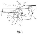
- a vehicle generally designated 10 is shown in a partial view.
- the vehicle 10 has an optical system 16 belonging to a head-up display 14 in a dashboard 12.
- the optical system 16 has a concave mirror 18 and a lens 20.
- a structural unit 22 is assigned to the optical system 16, which is connected via lines 24 with means 26 providing information, for example sensors, measuring devices, etc. connected is.
- a vehicle driver 28 is seated in the vehicle and looks into the windshield 30 while driving.
- the assembly 22 converts the information provided by the means 26 into optical signals and emits a light corresponding to the current display. This light is thrown onto the concave mirror 18 and an image corresponding to the display is projected from the latter onto the windshield 30 of the vehicle 10 in a region which can be predetermined by the position of the concave mirror 18.
- the vehicle driver 28 seated in the vehicle 10 now perceives the display as a virtual image at the point 32 in front of the windshield 30.
- the structural unit 22 emits optical signals in the infrared range, which are also reflected by the concave mirror 18 and through the windshield 30 in the region of the beam paths 34 indicated here in the direction of a beam not shown in FIG. 1 the beacon located in the vehicle are diverted.
- the beacon also has a transmitting and receiving unit which operates in the infrared range and which, when passing through the vehicle 10, uses the arrows 36 indicated here to exchange information with the infrared transmitting and receiving unit of the vehicle 10, which is arranged in the structural unit 22.
- This data exchange can be, for example, the recording of fees and billing as well as the granting of access control at a toll booth to be driven through on a motorway.
- the information signals emerge from the vehicle in an area of the windshield 30 which is of crucial importance for the driver's view 28.
- This area is generally located within the effective area of a windshield wiper, not shown here, so that this area is essentially freed from external contamination, and thus an obstruction to the optical data exchange between the vehicle 10 and the beacon passed through can be excluded.
- the data exchange takes place in an approximately vertical direction upwards, so that between vehicle 10 and Beacon the smallest possible distance is maintained at the time of the optical data exchange.
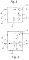
- the structure of the structural unit 22 is illustrated in FIG.
- the assembly 22 has a light source 38 and a display 40 which interacts with the light source 38. Furthermore, the assembly 22 has an infrared transmitter 42 and an infrared receiver 44.
- the light source 38 and the infrared transmitter 42 and the infrared receiver 44 are, as indicated, connected to other components, not shown here, for providing the information or for evaluation, based on their individual mode of action in the The scope of this invention is not to be discussed in detail.
- the light source 38 emits a light corresponding to certain information in the direction of the arrow 46, the light, as shown in FIG. 1, striking the concave mirror 18 and being reflected accordingly by the latter.
- This particularly simple and space-saving arrangement means that the optical components of the head-up display 14, in particular the concave mirror 18, can also be used, so that no additional installation space is required for further components.
- the infrared radiation can be decoupled by a partially transparent mirror, not shown here, arranged between the concave mirror 18 and the structural unit 22 and which only allows the infrared radiation to pass through.
- the infrared transmitter 42 is arranged independently of the light source 38 of the head-up display 14 and can also be decoupled by a partially transparent mirror, not shown here, which is arranged laterally next to the light source 38.
- the proportion of infrared radiation which is projected onto the windshield 30 via the concave mirror 18 and reaches the driver's eye there by reflection is outside the spectral sensitivity of the human eye and is therefore not perceived as a disturbance.
- FIG. 3 shows a further exemplary embodiment of the structural unit 22, the same parts being provided with the same reference symbols.
- the infrared transmitter 50 is designed here as part of the light source 38 for the head-up display 14.
- the light source 38 is modulated at a sufficiently high frequency so that a sufficiently high power can be emitted in the infrared range. At a sufficiently high frequency, this modulation of the light source 38 does not disturb the virtual image of the head-up display 14 which arises later.
- a first mirror 52 is arranged between the light source 38 and the display 40.
- This mirror 52 is designed as a partially transparent mirror, which only separates the infrared portion of the spectrum of the light source 38 and bypasses the display 40 via a second mirror 54 to the optical system 16 or the concave mirror 18.
- the visible part of the spectrum of the light source 38 is passed through the partially transparent mirror 52 and reaches the display 40 and is used here to generate the image of the head-up display 14.
- the infrared receiver 44 as already mentioned in FIG. 2, is designed and received separately the infrared rays deflected via the concave mirror 18, possibly with the interposition of a mirror, not shown here, which is partially transparent to infrared rays.
Abstract
Description
Die Erfindung betrifft eine Anordnung zur optischen Datenübertragung zwischen einer ortsfesten Verkehrseinrichtung, insbesondere einer Bake, und einem einzelnen, die Verkehrseinrichtung passierenden Fahrzeug, wobei die Verkehrseinrichtung und das Fahrzeug jeweils weinigstens eine Sende- und Empfangseinheit aufweisen, und die Verkehrseinrichtung Einrichtungen besitzt, die eine genaue Identifikation einzelner Fahrzeuge in bestimmten abgegrenzten Bereichen ermöglicht.The invention relates to an arrangement for optical data transmission between a stationary traffic device, in particular a beacon, and a single vehicle passing through the traffic device, the traffic device and the vehicle each having at least one transmitting and receiving unit, and the traffic device having devices that have an accurate Allows identification of individual vehicles in certain delimited areas.
Es ist bekannt, Informationen zwischen Fahrzeugen und einer ortsfesten Verkehrseinrichtung mittels optischer Datenübertragung, insbesondere mit Infrarotstrahlung, auszutauschen. Dieser optische Datenaustausch wird unter anderem in Verkehrsortungs- und -leitsystemen eingesetzt, um einerseits vom Fahrzeug Informationen und Daten, beispielsweise Reisezeiten und/oder Stauzeiten, an ortsfeste Verkehrseinrichtungen zu übertragen und um andererseits von den ortsfesten Verkehrseinrichtungen Informationen und Daten, wie beispielsweise Leitinformationen zur Zielführung des Fahrzeugs in das Fahrzeug zu übertragen.It is known to exchange information between vehicles and a stationary traffic facility by means of optical data transmission, in particular with infrared radiation. This optical data exchange is used, among other things, in traffic location and control systems, on the one hand to transmit information and data, for example travel times and / or traffic jams, from the vehicle to stationary traffic facilities and, on the other hand, from the stationary traffic facilities To transfer information and data, such as guidance information for the guidance of the vehicle into the vehicle.
Es ist vorgeschlagen worden, diese optische Datenübertragung zwischen ortsfester Verkehrseinrichtung und Fahrzeug bei der Erhebung von Gebühren zur Straßenbenutzung und der Zugangskontrolle der Fahrzeuge zu bestimmten Straßenabschnitten, beispielsweise bei Autobahnen, einzusetzen. Beim Einsatz dieser optischen Datenübertragung findet zwischen dem Fahrzeug und der ortsfesten Verkehrseinrichtung ein Dialog statt, der eine Identifikation des Fahrzeugs ermöglicht sowie eine genaue Zuordnung einer berechneten Gebühr für das spezielle Fahrzeug und eine Abbuchung bzw. Zuordnung der Gebühr zu dem Fahrzeug, einschließlich der Erteilung einer Zugangsberechtigung für das Fahrzeug, beinhaltet. Hierbei muß jedoch sichergestellt sein, da in der Regel, insbesondere bei Autobahnen, mehrere Fahrzeuge gleichzeitig über mehrere Spuren eine ortsfeste Verkehrseinrichtung passsieren können, daß ohne jeden Zweifel eine genaue Zuordnung bestimmter Informationen zu bestimmten Fahrzeugen erfolgen kann.It has been proposed to use this optical data transmission between the fixed traffic facility and the vehicle when charging road use fees and controlling the access of vehicles to certain road sections, for example on motorways. When using this optical data transmission, a dialogue takes place between the vehicle and the fixed traffic facility, which enables the vehicle to be identified, as well as an exact allocation of a calculated fee for the specific vehicle and a debiting or allocation of the fee to the vehicle, including the issue of a Access authorization for the vehicle included. In this case, however, it must be ensured that, as a rule, in particular, in the case of motorways, several vehicles can pass a stationary traffic facility at the same time via several lanes, that there can be no doubt that specific information can be assigned to specific vehicles.
In der EP 0 413 948 ist bereits vorgeschlagen worden, bei einer über mehrere Spuren einer Straße angebrachten brückenartigen Bake jeweils einer Fahrspur eine ortsfeste Sende- bzw. Empfangseinrichtung zuzuordnen, die durch eine Maske mit einer vorgebbaren Blendenöffnung in der Bildebene jeweils einer entsprechenden Wirkfläche im Fahrbereich, insbesondere einer Fahrspur, begrenzt ist, innerhalb welcher ein Informationsaustausch durch Lichtaussendung bzw. Lichtempfang mit einer Sende- bzw. Empfangseinrichtung des Fahrzeugs möglich ist. Es ist vorgesehen, um die Sende- und Empfangskeulen von Fahrzeug und Verkehrseinrichtung auf verschiedenen Fahrbahnen voneinander zu trennen, nicht nach vorn oder hinten, sondern direkt nach oben zu senden, da dadurch der geringste Abstand zwischen Fahrzeug und Bake bei der Durchfahrt unter der Verkehrseinrichtung ausgenutzt wird.It has already been proposed in EP 0 413 948 to assign a stationary transmission or reception device to a lane in the case of a bridge-like beacon attached over several lanes of a road, which means through a mask with a predeterminable aperture in the image plane in each case a corresponding effective area in the driving area , in particular a lane, is limited, within which an exchange of information by light emission or light reception with a transmitting or receiving device of the vehicle is possible. It is intended to separate the transmitting and receiving lobes of the vehicle and the traffic device from one another on different lanes, not to the front or to the rear, but to send them directly upwards, since this exploits the smallest distance between the vehicle and the beacon when passing under the traffic device becomes.
Hierzu ist vorgesehen, die Sende- und Empfangseinheit des Fahrzeugs zwischen Windschutzscheibe und Innenspiegel des Fahrzeugs als separate Einheit auszubilden und anzubringen. Hierbei ist jedoch nachteilig, da sich die Sende- und Empfangseinheit des Fahrzeugs zwar in einem Bereich befindet, der die Sicht des Fahrzeugführers nach vorne nicht beeinträchtigt, dieser Bereich von einem am Fahrzeug angebrachten Scheibenwischer nicht erfaßt wird, so daß bei einer nicht auszuschließenden äußeren Verschmutzung der Windschutzscheibe im Befestigungsbereich der Sende- und Empfangseinheit des Fahrzeugs es zu Verschmutzungen kommen kann, die eine optische Datenübertragung wesentlich beeinträchtigen. Gerade jedoch eine schlechte optische Datenübertragung kann zu Fehlinformationen führen, die eine sichere Zuordnung von Informationen zu einem bestimmten Fahrzeug verhindern.For this purpose, it is provided that the transmitting and receiving unit of the vehicle between the windshield and the inside mirror of the vehicle is designed and attached as a separate unit. However, this is disadvantageous since the transmitter and receiver unit of the vehicle is located in an area that does not impair the driver's view to the front, this area is not covered by a windshield wiper attached to the vehicle, so that external contamination cannot be ruled out the windshield in the fastening area of the transmitting and receiving unit of the vehicle, soiling can occur which significantly impair optical data transmission. However, poor optical data transmission can lead to incorrect information, which prevents a reliable assignment of information to a specific vehicle.
Weiterhin ist nachteilig, daß die Sende- und Empfangseinheit des Fahrzeugs als separates Bauteil ausgebildet ist und einen zusätzlichen Einbauplatz benötigt.Another disadvantage is that the transmitter and receiver unit of the vehicle is designed as a separate component and requires an additional installation space.
Der Erfindung liegt die Aufgabe zugrunde, eine Anordnung zur optischen Datenübertragung der gattungsgemäßen Art zu schaffen, mit der eine sichere und effektive Datenübertragung zwischen einer Verkehrseinrichtung und einem Fahrzeug mit geringem Aufwand möglich ist.The invention has for its object to provide an arrangement for optical data transmission of the generic type, with which a safe and effective data transmission between a traffic device and a vehicle is possible with little effort.
Erfindungsgemäß wird diese Aufgabe durch die kennzeichnenden Merkmale des Hauptanspruchs gelöst.According to the invention, this object is achieved by the characterizing features of the main claim.
Es wurde gefunden, daß wenn bei der Anordnung zur optischen Datenübertragung die Sende- und Empfangseinheit des Fahrzeugs Komponenten eines head-up displays aufweist, eine besonders einfache und platzsparende Anordnung möglich ist, da schon vorhandene optische und elektronische Bauelemente für das head-up display gleichzeitig zur optischen Datenübertragung an eine ortsfesten Verkehrseinrichtung mitbenutzt werden können. Sehr vorteilhaft ist dabei, da die optischen Komponenten des head-up displays sehr leistungsfähig sind, daß eine problemlose Datenübertragung zu der ortsfesten Verkehrseinrichtung möglich ist. Gleichzeitig erfolgt die Datenübertragung zwischen dem Fahrzeug und der Verkehrseinrichtung in einem Bereich des Fahrzeugs, der durch am Fahrzeug angebrachte Scheibenwischer im Bereich der Frontscheibe bei beeinträchtigter Sicht durch den Fahrzeugführer in aller Regel gereinigt wird, so daß eine äußere Verschmutzung des Fahrzeugs keine negativen Einflüsse auf die optische Datenübertragung haben kann.It has been found that if the transmitter and receiver unit of the vehicle has components of a head-up display in the arrangement for optical data transmission, a particularly simple and space-saving arrangement is possible since existing optical and electronic components for the head-up display are used simultaneously can be used for optical data transmission to a fixed traffic facility. It is very advantageous here, since the optical components of the head-up display are very powerful, that problem-free data transmission to the stationary traffic facility is possible. At the same time, the data transmission between the vehicle and the traffic device takes place in an area of the vehicle which is usually cleaned by windshield wipers attached to the vehicle in the area of the front window in the event of impaired visibility by the driver, so that external contamination of the vehicle has no negative effects on the vehicle can have optical data transmission.
In Ausgestaltung der Erfindung ist vorgesehen, daß für die optische Datenübertragung und für die Bereitstellung eines virtuellen Bildes über das head-up display ein gemeinsames optisches System verwendet wird. Hierbei ist sehr vorteilhaft, da das optische System für das head-up display sehr leistungsstark ist, daß diese Komponenten für eine sehr effiziente Datenübertragung mitgenutzt werden können und bei Verwendung sowieso vorhandener optischer Komponenten kein zusätzliches Einbauvolumen im Bereich des Armaturenbrettes des Fahrzeugs benötigt wird.In an embodiment of the invention it is provided that a common optical system is used for the optical data transmission and for the provision of a virtual image via the head-up display. It is very advantageous here, since the optical system for the head-up display is very powerful, that these components can be used for a very efficient data transmission and when using existing optical components, no additional installation volume is required in the area of the dashboard of the vehicle.
So ist in weiterer vorteilhafter Ausgestaltung der Erfindung vorgesehen, daß das optische System derart ausgebildet ist, daß es die für die Bildung des virtuellen Bildes und die für die Datenübertragung benötigten Signale separieren kann. Dies erfolgt vorteilhafterweise durch Anordnung eines nur die optischen Daten reflektierenden Spiegels oder eines teildurchlässigen Spiegels, so daß die Signale sicher auseinander gehalten werden können.It is provided in a further advantageous embodiment of the invention that the optical system is designed such that it can separate the signals required for the formation of the virtual image and the signals required for data transmission. This is advantageously done by arranging a mirror reflecting only the optical data or a partially transparent mirror, so that the signals can be kept apart safely.
Weitere vorteilhafte Ausgestaltungen der Erfindung ergeben sich aus den in den Unteransprüchen aufgeführten Maßnahmen.Further advantageous refinements of the invention result from the measures listed in the subclaims.
Die Erfindung wird nachfolgend in Ausführungsbeispielen anhand der zugehörigen Zeichnungen näher erläutert. Es zeigen:
Figur 1- eine Teilansicht eines Fahrzeugs im Schnitt;
- Figur 2
- einen Teil des optische Systems im Blockschaltbild und
- Figur 3
- einen Teil des optischen Systems im Blockschaltbild in einem weiteren Ausführungsbeispiel.
- Figure 1
- a partial view of a vehicle in section;
- Figure 2
- part of the optical system in the block diagram and
- Figure 3
- a part of the optical system in the block diagram in a further embodiment.
In Figur 1 ist ein allgemein mit 10 bezeichnetes Fahrzeug in einer Teilansicht gezeigt. Das Fahrzeug 10 weist in einem Armaturenbrett 12 ein zu einem head-up display 14 gehörendes optisches System 16 auf. Das optische System 16 besitzt einen Hohlspiegel 18 sowie eine Linse 20. Dem optischen System 16 ist eine Baueinheit 22 zugeordnet, die über Leitungen 24 mit Informationen bereitstellenden Mitteln 26, beispielsweise Sensoren, Meßgeräten u.s.w. verbunden ist. In dem Fahrzeug sitzt ein Fahrzeugführer 28, der während der Fahrt in Richtung der Windschutzscheibe 30 blickt.In Figure 1, a vehicle generally designated 10 is shown in a partial view. The
Nachfolgend soll die Funktion des head-up displays 14 zum besseren Verständnis beschrieben werden. Die Baueinheit 22 wandelt die von den Mitteln 26 bereitgestellten Informationen in optische Signale um und sendet ein der momentanen Anzeige entsprechendes Licht aus. Dieses Licht wird auf den Hohlspiegel 18 geworfen und von diesem ein der Anzeige entsprechendes Bild über die Linse 20 auf die Windschutzscheibe 30 des Fahrzeugs 10 in einem durch die Stellung des Hohlspiegels 18 vorherbestimmbaren Bereich projiziert. Der in dem Fahrzeug 10 sitzende Fahrzeugführer 28 nimmt nunmehr die Anzeige als virtuelles Bild an der Stelle 32 vor der Windschutzscheibe 30 wahr. Auf weitere Einzelheiten der Entstehung des virtuellen Bildes entsprechend der über die Baueinheit 22 bereitgestellten Anzeige soll hier nicht weiter eingegangen werden. Die Baueinheit 22 sendet neben den für die Bereitstellung des virtuellen Bildes notwendigen Informationen optische Signale im Infrarotbereich aus, die ebenfalls über den Hohlspiegel 18 reflektiert und durch die Windschutzscheibe 30 im Bereich der hier angedeuteten Strahlengänge 34 in Richtung auf eine in Figur 1 nicht dargestellte, über dem Fahrzeug befindliche Bake umgelenkt werden. Die Bake besitzt ebenfalls eine Sende- und Empfangseinheit, die im Infrarotbereich arbeitet und die bei Passieren des Fahrzeugs 10 durch die hier angedeuteten Pfeile 36 Informationen mit der Infrarotsende- und Empfangseinheit des Fahrzeugs 10, die in der Baueinheit 22 angeordnet ist, austauscht. Dieser Datenaustausch kann beispielsweise die Gebührenerfassung und Abrechnung sowie Erteilung einer Zugangskontrolle an einer auf einer Autobahn zu durchfahrenden Mautstelle sein. Dadurch daß für die optische Infrarotdatenübertragung die Komponenten des head-up displays 14 mit verwendet werden, treten die Informationssignale in einem Bereich der Windschutzscheibe 30 aus dem Fahrzeug aus, der für die Sicht des Fahrzeugführers 28 von ganz entscheidender Bedeutung ist. Dieser Bereich befindet sich in aller Regel innerhalb des Wirkbereiches eines hier nicht dargestellten Scheibenwischers, so daß dieser Bereich im wesentlichen von äußeren Verschmutzungen befreit ist, und damit eine Behinderung des optischen Datenaustausches zwischen dem Fahrzeug 10 und der durchfahrenen Bake ausgeschlossn werden kann. Gleichzeitig findet der Datenaustausch in annähernd senkrechter Richtung nach oben statt, so daß zwischen Fahrzeug 10 und Bake zum Zeitpunkt des optischen Datenaustausches der geringst mögliche Abstand gewahrt ist.The function of the head-up
In Figur 2 wird der Aufbau der Baueinheit 22 verdeutlicht. Die Baueinheit 22 weist eine Lichtquelle 38 sowie ein mit der Lichtquelle 38 zusammenwirkendes Display 40 auf. Weiterhin besitzt die Baueinheit 22 einen Infrarotsender 42 und einen Infrarotempfänger 44. Die Lichtquelle 38 sowie der Infrotsender 42 und der Infrarotempfänger 44 sind, wie angedeutet, mit weiteren hier nicht dargestellten Bauteilen zur Bereitstellung der Informationen bzw. zur Auswertung verbunden, auf deren einzelne Wirkungsweise im Rahmen dieser Erfindung nicht näher eingegangen werden soll. Die Lichtquelle 38 sendet in Verbindung mit dem Display 40 ein einer bestimmten Information entsprechendes Licht in Richtung des Pfeiles 46 aus, wobei das Licht, wie in Figur 1 gezeigt, auf den Hohlspiegel 18 trifft und von diesem entsprechend reflektiert wird. Der Infrarotsender 42 sendet im nicht sichtbaren Bereich liegende optische Infrarotsignale aus (Pfeil 47), die ebenfalls auf den Hohlspiegel 18 treffen und von diesem reflektiert werden. Die von der bereits erwähnten Bake kommenden Informationen im Infrarotbereich werden durch den Hohlspiegel 18 auf die Baueinheit 22 reflektiert und hier vom Infrarotempfänger 44, wie durch den Pfeil 48 angedeutet, aufgenommen und einer weiteren Verarbeitung zugeführt.The structure of the
Durch diese besonders einfache und platzsparende Anordnung ergibt sich, daß die optischen Komponenten des head-up displays 14, insbesondere des Hohlspiegels 18, mitbenutzt werden können und so kein zusätzlicher Einbauraum für weitere Komponenten notwendig ist. Zur besseren Herausfilterung des für den Infrarotempfänger 44 bestimmten Lichtanteils kann die Infrarotstrahlung durch einen hier nicht dargestellten, zwischen Hohlspiegel 18 und Baueinheit 22 angeordneten, teildurchlässigen Spiegel, der nur die Infrarotstrahlung durchläßt, entkoppelt werden.This particularly simple and space-saving arrangement means that the optical components of the head-up
Der Infrarotsender 42 ist unabhägig von der Lichtquelle 38 des head-up displays 14 angeordnet und kann ebenfalls durch einen hier nicht dargestellten teildurchlässigen Spiegel, der seitlich neben der Lichtquelle 38 angeordnet ist, entkoppelt werden. Der Anteil der Infrarotstrahlung, welcher über den Hohlspiegel 18 an die Windschutzscheibe 30 projiziert wird und dort durch Reflexion in das Auge des Fahrers gelangt, liegt außerhalb der spektralen Empfindlichkeit des menschlichen Auges und wird daher nicht störend wahrgenommen.The
In Figur 3 ist ein weiteres Ausführungsbeispiel der Baueinheit 22 gezeigt, wobei gleiche Teile mit gleichen Bezugszeichen versehen sind. Der Infrarotsender 50 ist hier als Teil der Lichtquelle 38 für das head-up display 14 ausgeführt. Die Lichtquelle 38 wird dabei mit genügend hoher Frequenz moduliert, damit eine genügend hohe Leistung im Infrarotbereich emittiert werden kann. Diese Modulation der Lichtquelle 38 stört bei genügend hoher Frequenz nicht das später entstehende virtuelle Bild des head-up display 14. Zwischen Lichtquelle 38 und Display 40 ist ein erster Spiegel 52 angeordnet.FIG. 3 shows a further exemplary embodiment of the
Dieser Spiegel 52 ist als teildurchlässiger Spiegel ausgebildet, der nur den Infrarotanteil des Spektrums der Lichtquelle 38 abtrennt und diesen über einen zweiten Spiegel 54 am Display 40 vorbei dem optischen System 16 bzw. dem Hohlspiegel 18 zuleitet. Der sichtbare Teil des Spektrums der Lichtquelle 38 wird durch den teildurchlässigen Spiegel 52 hindurchgelassen und gelangt zum Display 40 und dient hier zur Erzeugung des Bildes des head-up displays 14. Der Infrarotempfänger 44 ist, wie bereits in Figur 2 erwähnt, separat ausgebildet und empfängt die über den Hohlspiegel 18 umgelenkten Infrarotstrahlen unter eventueller Zwischenschaltung eines hier nicht dargestellten, für Infrarotstrahlen teildurchlässigen Spiegels direkt. Durch die Ausnutzung der Lichtquelle 38 neben der Bereitstellung für das virtuelle Bild des head-up display 14 gleichzeitig als Infrarotsender kann ein weiteres bereits vorhandenes leistungsstarkes Bauteil für die optische Datenübertragung im Infrarotbereich mit genutzt werden, ohne daß zusätzliche aufwendige Maßnahmen zu treffen sind.This
Claims (8)
Applications Claiming Priority (2)
| Application Number | Priority Date | Filing Date | Title |
|---|---|---|---|
| DE4307354A DE4307354A1 (en) | 1993-03-09 | 1993-03-09 | Arrangement for optical data transmission |
| DE4307354 | 1993-03-09 |
Publications (3)
| Publication Number | Publication Date |
|---|---|
| EP0615022A2 true EP0615022A2 (en) | 1994-09-14 |
| EP0615022A3 EP0615022A3 (en) | 1995-12-20 |
| EP0615022B1 EP0615022B1 (en) | 1998-12-30 |
Family
ID=6482298
Family Applications (1)
| Application Number | Title | Priority Date | Filing Date |
|---|---|---|---|
| EP94102455A Expired - Lifetime EP0615022B1 (en) | 1993-03-09 | 1994-02-18 | Device for optical data transmission |
Country Status (2)
| Country | Link |
|---|---|
| EP (1) | EP0615022B1 (en) |
| DE (2) | DE4307354A1 (en) |
Cited By (3)
| Publication number | Priority date | Publication date | Assignee | Title |
|---|---|---|---|---|
| GB2300322A (en) * | 1995-04-25 | 1996-10-30 | Siemens Ag | Combined infra-red and telephone communications for computers |
| EP0759603A1 (en) * | 1995-08-18 | 1997-02-26 | Agency Of Industrial Science And Technology | Route guide system and method |
| WO2007020255A1 (en) * | 2005-08-18 | 2007-02-22 | Siemens Aktiengesellschaft | Display system for a motor vehicle |
Families Citing this family (7)
| Publication number | Priority date | Publication date | Assignee | Title |
|---|---|---|---|---|
| DE4437408A1 (en) * | 1994-10-19 | 1995-03-23 | Jaehnke Klaus Peter | Transmitting/receiving parts for acoustic, image-like signals, which parts are constructed to form, for motorised vehicles, an installation for emergencies, for ordering road users to do something, for making them aware of dangers and for warning them |
| DE29711094U1 (en) * | 1997-06-25 | 1997-09-04 | Nguyen Petersen Chanh Dinh Dr | Display device for motor vehicles |
| DE19731320A1 (en) * | 1997-07-22 | 1998-04-16 | Pitt Fischer | Electronic transceiver unit for vehicle |
| DE19735523A1 (en) * | 1997-08-16 | 1999-02-18 | Alsthom Cge Alcatel | Information exchange process, interrogation station and reply station therefor |
| DE19753511A1 (en) * | 1997-12-03 | 1999-06-10 | Zlatko Veber | Warning detection method for road traffic |
| FR2860906B1 (en) * | 2003-10-14 | 2008-06-06 | Andre Pecque | DEVICE FOR DRIVING VEHICLES |
| DE102014003937B4 (en) * | 2014-03-19 | 2022-06-15 | Audi Ag | Method for bidirectional communication between a motor vehicle and an infrastructure facility and motor vehicle |
Citations (3)
| Publication number | Priority date | Publication date | Assignee | Title |
|---|---|---|---|---|
| EP0413948A1 (en) * | 1989-08-21 | 1991-02-27 | Siemens Aktiengesellschaft | System for optical data transmission, preferably for the automatic payment of road taxes |
| US5182555A (en) * | 1990-07-26 | 1993-01-26 | Farradyne Systems, Inc. | Cell messaging process for an in-vehicle traffic congestion information system |
| US5198797A (en) * | 1990-05-11 | 1993-03-30 | Nissan Motor Co., Ltd. | Heads-up display arrangement for vehicle |
-
1993
- 1993-03-09 DE DE4307354A patent/DE4307354A1/en not_active Withdrawn
-
1994
- 1994-02-18 EP EP94102455A patent/EP0615022B1/en not_active Expired - Lifetime
- 1994-02-18 DE DE59407548T patent/DE59407548D1/en not_active Expired - Fee Related
Patent Citations (3)
| Publication number | Priority date | Publication date | Assignee | Title |
|---|---|---|---|---|
| EP0413948A1 (en) * | 1989-08-21 | 1991-02-27 | Siemens Aktiengesellschaft | System for optical data transmission, preferably for the automatic payment of road taxes |
| US5198797A (en) * | 1990-05-11 | 1993-03-30 | Nissan Motor Co., Ltd. | Heads-up display arrangement for vehicle |
| US5182555A (en) * | 1990-07-26 | 1993-01-26 | Farradyne Systems, Inc. | Cell messaging process for an in-vehicle traffic congestion information system |
Non-Patent Citations (1)
| Title |
|---|
| PATENT ABSTRACTS OF JAPAN vol. 7 no. 176 (P-214) [1321] ,4.August 1983 & JP-A-58 080616 (MITSUBISHI DENKI K.K.) 14.Mai 1983, * |
Cited By (5)
| Publication number | Priority date | Publication date | Assignee | Title |
|---|---|---|---|---|
| GB2300322A (en) * | 1995-04-25 | 1996-10-30 | Siemens Ag | Combined infra-red and telephone communications for computers |
| GB2300322B (en) * | 1995-04-25 | 1997-04-09 | Siemens Ag | System for locally flexible telecommunication |
| EP0759603A1 (en) * | 1995-08-18 | 1997-02-26 | Agency Of Industrial Science And Technology | Route guide system and method |
| US5731766A (en) * | 1995-08-18 | 1998-03-24 | Agency Of Industrial Science And Technology | Route guide system and method |
| WO2007020255A1 (en) * | 2005-08-18 | 2007-02-22 | Siemens Aktiengesellschaft | Display system for a motor vehicle |
Also Published As
| Publication number | Publication date |
|---|---|
| DE4307354A1 (en) | 1994-09-15 |
| EP0615022A3 (en) | 1995-12-20 |
| DE59407548D1 (en) | 1999-02-11 |
| EP0615022B1 (en) | 1998-12-30 |
Similar Documents
| Publication | Publication Date | Title |
|---|---|---|
| DE10002069C2 (en) | Arrangement to improve visibility in vehicles | |
| DE112004000035B4 (en) | Sensor arrangement for distance and / or speed measurement | |
| DE102006003785A1 (en) | Motor vehicle surrounding and interior detection sensor for e.g. pre-crash system, has controllable dimming device provided before optical receiving unit, where dimming device comprises photochromatic and/r electrochromatic medium | |
| EP1831717B1 (en) | Optical short-range sensor | |
| EP1159169B1 (en) | Optoelectronic monitoring device for a motor vehicle | |
| DE4413886C1 (en) | System for detecting (collecting) traffic information in vehicles | |
| EP1446678B1 (en) | Method and device for detecting and classifying moving vehicles | |
| DE102009060392A1 (en) | Sensor device for use in windscreen of motor vehicle for providing e.g. information about surrounding of vehicle to driver assistance system, has adjusting device for three dimensionally adjusting housing modules relative to each other | |
| DE19829162A1 (en) | Application of electronic camera and image recognition device in car for detecting traffic signs | |
| DE4206142A1 (en) | Vehicle arrangement for visibility-dependent control of fog lamps - adjusts brightness of visible lamps in proportion to intensity of back-scatter of infrared radiation by atmosphere droplets | |
| DE102017218683A1 (en) | Vehicle-based lidar system | |
| EP0615022B1 (en) | Device for optical data transmission | |
| DE10146808A1 (en) | Optical system or motor vehicle has sensor units at different positions in or on vehicle with transmission and reception optics, central module with measurement, control and changeover units | |
| DE3903501A1 (en) | Optical distance measuring apparatus for vehicles | |
| EP1536978A1 (en) | Vehicle environment detection device | |
| EP0413948B1 (en) | System for optical data transmission, preferably for the automatic payment of road taxes | |
| DE102009035984A1 (en) | Multi-functional running time sensor for use in e.g. external rear mirror of bus for spatial scanning of trunk road, has receiving unit comprising lens, where sensor scans surfaces at different angle ranges, during rotation of lens | |
| DE4239061A1 (en) | Rear obstruction warning transceiver system for goods vehicle - has pulsed infrared laser and scanner contg. rotary prism and scan position detectors, with electrical interface to ignition which is cut=out when measured distance to obstacle crosses min. sepn. threshold | |
| EP0083769A2 (en) | Rear view mirror device for a vehicle | |
| DE10162009B4 (en) | Optical system | |
| DE3635689C2 (en) | ||
| DE102012019621A1 (en) | Rain sensor, motor vehicle and method for detecting the intensity of a precipitate | |
| DE102016001231A1 (en) | Method for determining a route | |
| EP1019748B1 (en) | Opto-electronic measuring device | |
| DE102019106901A1 (en) | Communication device of a motor vehicle, illumination device of a motor vehicle for the communication device of a motor vehicle and method for car2car or car2X communication of a motor vehicle |
Legal Events
| Date | Code | Title | Description |
|---|---|---|---|
| PUAI | Public reference made under article 153(3) epc to a published international application that has entered the european phase |
Free format text: ORIGINAL CODE: 0009012 |
|
| AK | Designated contracting states |
Kind code of ref document: A2 Designated state(s): DE FR IT SE |
|
| PUAL | Search report despatched |
Free format text: ORIGINAL CODE: 0009013 |
|
| AK | Designated contracting states |
Kind code of ref document: A3 Designated state(s): DE FR IT SE |
|
| 17P | Request for examination filed |
Effective date: 19960620 |
|
| GRAG | Despatch of communication of intention to grant |
Free format text: ORIGINAL CODE: EPIDOS AGRA |
|
| 17Q | First examination report despatched |
Effective date: 19980421 |
|
| GRAG | Despatch of communication of intention to grant |
Free format text: ORIGINAL CODE: EPIDOS AGRA |
|
| GRAH | Despatch of communication of intention to grant a patent |
Free format text: ORIGINAL CODE: EPIDOS IGRA |
|
| GRAH | Despatch of communication of intention to grant a patent |
Free format text: ORIGINAL CODE: EPIDOS IGRA |
|
| GRAA | (expected) grant |
Free format text: ORIGINAL CODE: 0009210 |
|
| AK | Designated contracting states |
Kind code of ref document: B1 Designated state(s): DE FR IT SE |
|
| REF | Corresponds to: |
Ref document number: 59407548 Country of ref document: DE Date of ref document: 19990211 |
|
| ET | Fr: translation filed | ||
| ITF | It: translation for a ep patent filed |
Owner name: STUDIO JAUMANN P. & C. S.N.C. |
|
| PLBE | No opposition filed within time limit |
Free format text: ORIGINAL CODE: 0009261 |
|
| STAA | Information on the status of an ep patent application or granted ep patent |
Free format text: STATUS: NO OPPOSITION FILED WITHIN TIME LIMIT |
|
| 26N | No opposition filed | ||
| PGFP | Annual fee paid to national office [announced via postgrant information from national office to epo] |
Ref country code: FR Payment date: 20030221 Year of fee payment: 10 |
|
| PGFP | Annual fee paid to national office [announced via postgrant information from national office to epo] |
Ref country code: SE Payment date: 20030225 Year of fee payment: 10 |
|
| PGFP | Annual fee paid to national office [announced via postgrant information from national office to epo] |
Ref country code: DE Payment date: 20030325 Year of fee payment: 10 |
|
| PG25 | Lapsed in a contracting state [announced via postgrant information from national office to epo] |
Ref country code: SE Free format text: LAPSE BECAUSE OF NON-PAYMENT OF DUE FEES Effective date: 20040219 |
|
| PG25 | Lapsed in a contracting state [announced via postgrant information from national office to epo] |
Ref country code: DE Free format text: LAPSE BECAUSE OF NON-PAYMENT OF DUE FEES Effective date: 20040901 |
|
| EUG | Se: european patent has lapsed | ||
| PG25 | Lapsed in a contracting state [announced via postgrant information from national office to epo] |
Ref country code: FR Free format text: LAPSE BECAUSE OF NON-PAYMENT OF DUE FEES Effective date: 20041029 |
|
| REG | Reference to a national code |
Ref country code: FR Ref legal event code: ST |
|
| PG25 | Lapsed in a contracting state [announced via postgrant information from national office to epo] |
Ref country code: IT Free format text: LAPSE BECAUSE OF NON-PAYMENT OF DUE FEES Effective date: 20050218 |