EP0613107A1 - Document deposit apparatus - Google Patents
Document deposit apparatus Download PDFInfo
- Publication number
- EP0613107A1 EP0613107A1 EP94301211A EP94301211A EP0613107A1 EP 0613107 A1 EP0613107 A1 EP 0613107A1 EP 94301211 A EP94301211 A EP 94301211A EP 94301211 A EP94301211 A EP 94301211A EP 0613107 A1 EP0613107 A1 EP 0613107A1
- Authority
- EP
- European Patent Office
- Prior art keywords
- documents
- temporary store
- document
- deposit
- contents
- Prior art date
- Legal status (The legal status is an assumption and is not a legal conclusion. Google has not performed a legal analysis and makes no representation as to the accuracy of the status listed.)
- Granted
Links
Images


Classifications
-
- G—PHYSICS
- G07—CHECKING-DEVICES
- G07D—HANDLING OF COINS OR VALUABLE PAPERS, e.g. TESTING, SORTING BY DENOMINATIONS, COUNTING, DISPENSING, CHANGING OR DEPOSITING
- G07D11/00—Devices accepting coins; Devices accepting, dispensing, sorting or counting valuable papers
- G07D11/009—Depositing devices
- G07D11/0096—Accepting paper currency or other valuables in containers, e.g. in code-marked envelopes
-
- E—FIXED CONSTRUCTIONS
- E05—LOCKS; KEYS; WINDOW OR DOOR FITTINGS; SAFES
- E05G—SAFES OR STRONG-ROOMS FOR VALUABLES; BANK PROTECTION DEVICES; SAFETY TRANSACTION PARTITIONS
- E05G7/00—Safety transaction partitions, e.g. movable pay-plates; Bank drive-up windows
- E05G7/001—Bank depositories
Definitions
- the invention relates to document deposit apparatus, for example for banknotes, cheques or other security documents.
- Cash Dispensers to assist Bank Tellers is well known. They provide Banks with advantages in Productivity, Accounting accuracy and Security. Further, when connected “Online” they permit easy interchange of staff at lunch and other "break” times with minimal cash balancing activities and consequent cost and delays. However, since most Tellers take in deposits of cash and cheques in addition to dispensing, there is currently unavoidable need to count/balance such deposits at change over times to protect both Bank and Tellers.
- the object of this invention is to provide an automated Deposit facility which may be connected online to a Bank's host computer and thereby eliminate the need for regular/intermediate manual cash balancing.
- Complex devices are available, from Japan and other sources, which provide this service. However, they are generally both too large and too costly for many Banks to justify commercially.
- US-A-4889220 describes a document deposit apparatus in which documents are fed through a discriminator which determines whether or not the documents are valid. Valid documents are then fed to a valid document temporary store and invalid documents to an invalid document temporary store. The user is then allowed access to the invalid document temporary store so that he can withdraw the documents and re-feed them.
- GB 2073718 in which documents are discriminated and then fed to either a valid or invalid temporary store. As explained above, however, these systems are complex and bulky and not well suited to the rugged environment of banks and the like where they are used.
- document deposit apparatus comprises a document inlet into which documents to be deposited are inserted; processing means for monitoring at least for the presence of a document; transport means for transporting documents from the document inlet through the processing means; a temporary store to which the documents from the processing means are fed by the transport means, the temporary store being accessible to a user from outside the apparatus through an access door; and control means for indicating to the user the contents of the temporary store and, when the user agrees with the contents, for passing the documents in the temporary store to a deposit region and is characterised in that the transport means feeds all documents passing through the processing means to the same temporary store.
- the invention provides a very simple document deposit apparatus which is easy to use by, for example, a bank Teller but which provides a bank customer with considerable confidence that the documents he is depositing have been correctly recorded.
- simplicity in performance and construction is achieved by providing the temporary store at a position at which it is accessible by the user from outside the apparatus and by transporting all documents to the same temporary store.
- the access door may be permanently locked, for example by a key, and only be unlocked if the user does not agree that the contents of the temporary store are correct.
- the access door is normally closed, the apparatus further comprising a door lock which is normally unlocked but which is locked by the control means at least after the user has agreed the contents of the temporary store.
- the access door is at least partially transparent to enable the contents of the temporary store to be viewed. This provides an even higher degree of confidence to the user.
- control means is responsive to the position of the access door to cancel the transaction and prevent documents being fed into the deposit region as soon as the door is opened.
- the documents in the temporary store could be conveyed by conveying means such as belts and the like to a remote deposit region.
- the deposit region is positioned adjacent to the temporary store in order to reduce as far as possible the size of the apparatus.
- the deposit region is positioned beneath the temporary store.
- the documents in the temporary store could be pushed into the deposit region but preferably the floor of the temporary store is moveable to allow the documents to drop under gravity into the deposit region.
- the deposit region itself may be defined by a bag or other insecure container or a cassette or the like.
- more than one deposit region could be provided.
- a second deposit region may be provided adjacent the first deposit region, the apparatus further comprising means for passing documents in the temporary store to the second deposit region.
- this means could comprise a slidable frame which slides over the floor of the temporary store to draw the documents to a position above the second deposit region.
- the processing means may comprise any document detector, for example as described in EP-A-0168202.
- the processing means preferably determines one or more characteristics of the documents, such as the length of the document in the feed direction which is often characteristic of the denomination of the document.
- the apparatus will normally store data defining the dimensions of the different documents which it is expected to handle so that it can perform an identification process on the documents which are fed.
- the processing means may include an ultraviolet sensor and/or a magnetic sensor for carrying out conventional ultraviolet or magnetic analysis of the documents.
- a detector is positioned in the temporary store to indicate the presence of documents in the temporary store.
- This detector can be used by the control means to ensure that all documents in the temporary store have passed to the deposit region or have been removed before the feeding of further documents in a subsequent operation is permitted.
- the operator is able to process and enter manually the value of documents which are not recognised by the apparatus detectors or fall outside the parameters set for the documents that are expected by the apparatus.
- the apparatus could be used as a stand alone module or as an accessory product to a Teller cash dispenser or the like. When used with a dispenser, it could be arranged that banknotes accepted by the apparatus are fed to a deposit region which can be accessed by a cash dispenser. In this way, the banknotes can be recycled.
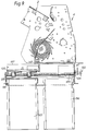
- the apparatus shown in Figures 1-6 is mounted within a steel enclosure 1 and includes a document feed hopper 2 mounted beneath an inlet opening 3 in the enclosure 1.
- the deposit module is mounted to the front of a conventional cash dispenser 19 (not shown).
- the hopper 2 forms part of a sheet processing apparatus 4 similar to the De La Rue 2520 sheet counter which is described in more detail in EP-A-0168202.
- the counter 4 comprises a metal housing 1' part of which defines the input hopper 2.
- Two conventional picker wheels 5 are rotatably mounted to the housing 1' and have radially outwardly projecting bosses 6 which, as the picker wheels rotate, periodically protrude through slots in the front of the hopper 2.
- a pair of drive rolls 15 are non-rotatably mounted to a drive shaft 16 which is rotatably mounted to the housing 1.
- Each drive roll 15 has an outer annular portion 17 of rubber.
- Each drive roll 15 contacts a respective auxiliary roll 18 rotatably mounted on a shaft 14.
- a pair of stripper rollers 19 are rotatably mounted on a shaft 20 having a larger diameter than the shaft 16 about which it is positioned.
- the shaft 20 is secured between a pair of arms 21 of a cradle 22.
- the cradle 22 is rotatably mounted to an auxiliary drive shaft 23 on which the picker wheels 5 are mounted.
- the cradle 22 has a cam portion 24 which engages a cam 25 rotatably mounted on the housing 1'. Manual rotation of the cam 25 forces the stripper rollers 19 towards the separation rollers 10 to define gaps of controlled width.
- Removable guiding 7 having a curved guide surface 8 extends partly around the circumference of the rollers 15,19 allowing the operator access to the note feed path so that a note jam can be cleared.
- Two separation rollers 10 (only one shown in the drawings) are rotatably mounted to a shaft 11 supported between lugs 9.
- a drive motor 30 (shown schematically in Figure 2) continuously drives the drive shaft 16 via a drive belt 31.
- the connection between the drive belt 31 and the drive shaft 16 has been omitted for clarity.
- the auxiliary drive shaft 23 is driven via a drive belt 32 by a drive motor 33 and is connected by a drive belt (not shown) to the stripper roller 19.
- a guide plate 34 extends from adjacent the nips formed between the drive rolls 15 and auxiliary rolls 18 to a conventional stacker wheel 35 rotatably mounted on the housing 1'.
- the drive rolls 15 and auxiliary rolls 18 define sheet sensing apparatus for detecting the passage of two or more notes simultaneously and for counting banknotes.
- the drive rollers and auxiliary rolls are spaced apart by a distance less than the width of sheets being counted.
- the shaft 14 is hollow, and is non-rotatably supported by the housing 1', and carries the two auxiliary rolls or roller assemblies 18. These are identical in construction and each contacts a respective one of the drive rolls 15.
- Each roller assembly 18 comprises a roller bearing having an annular outer race 38 ( Figures 3 and 4), an annular inner race 39 and bearings 40 positioned between the inner and outer races.
- the bearing is mounted coaxially about the shaft 14 on an annular rubber portion 41.
- a metal pin 42 abuts the radially inner surface of the inner race 39 and extends through the rubber portion 41 and an aperture 43 in the shaft 14 into the shaft.
- a moulded plastics housing 44 is mounted within the shaft 14 and comprises a central tubular portion 45 integral with end portions 46 each of which has a bore 47 communicating with the tubular portion 45.
- a pair of light emitting diodes 48 are mounted in the inner ends of the bores 47 while a pair of phototransistors 49 are mounted at the outer ends of the bores 47.
- These wires will pass along and out of the shaft 14 to monitoring circuitry to be described below and to facilitate assembly, all wires extend from the same end of the shaft.
- Each portion 46 of the housing 44 also has an aperture 50 communicating with the bore 47 and in alignment with the aperture 32. The pins 42 extend through the apertures 50 into the bores 47.
- Figure 5 illustrates the two light emitting diodes 48 and the phototransistors 49 each of which is connected to a power source 51.
- the section of the circuit shown enclosed in dashed lines is that section mounted in the plastics housing 44.
- the output from each phototransistor 49 is fed via respective amplifiers and A/D converters 52 to a microcomputer 53 which constitutes the main controller for the counter.
- each roller assembly 18 Initially, the drive rolls 15 are rotated and with no sheet present between the drive rolls 15 and roller assemblies 18, any deflection of each roller assembly 18 accompanied by compression of respective resilient portions 41 adjacent the drive rolls 15 will be sensed typically at forty equally spaced intervals through one revolution of the roller assemblies 18. Compression of each rubber portion 41 in a radially inward direction will be accompanied by radially inward movement of each pin 42.
- Each LED 48 continuously emits light which impinges on respective phototransistors 49 causing them normally to be partially switched on. If a pin 42 moves radially inwardly, the pin 42 will increasingly obscure the path of optical rays from the LED's to the phototransistors 49 thus increasing the amount by which the phototransistors 49 are cut off.
- the output from the phototransistors 49 is fed via the amplifiers and A to D converters 52 to the microprocessor 53.
- the microcomputer 53 generates an error signal which is fed back to the amplifiers 52 via D to A converters 55 to bring the signal back to a reference value. This is done at forty equally spaced sampling positions around the drive rolls 15 (which will be determined by monitoring a timing disc (not shown) mounted non-rotatably to the shaft 16). This produces forty sampled voltage values which are then stored in respective memories 54 as a guide surface profile or datum level. A similar system is explained in more detail in EP-A-0168202.
- a stack of banknotes is placed in the input hopper 4.
- the drive motors 30,33 are actuated so that both the drive shaft 16 and the auxiliary drive shaft 23 rotate.
- Rotation of the picker wheels 5 causes banknotes at the bottom of the stack to be urged towards a nip 38 between the stripper rollers 19 and the separation rollers 10.
- the width of the gaps between the stripper rollers 19 and separation rollers 10 will prevent more than one note being fed by the stripper rollers 19.
- the note will be fed between the drive rolls 15 and the auxiliary rolls 18 due to the continuous rotation of the shaft 16, the note being fed along the guide plate 34 into the stacker wheel 35 which is being rotated by the drive motor 30 and which will stack the note fed in the output hopper 37.
- the corresponding rubber portions 41 will be compressed with accompanying radially inward movement of each pin 42. This will cause a variation in the light received by the phototransistors 49 which is monitored at the same forty sampling positions. The monitored values are then compared with the previously stored datum and the difference compared with a threshold to indicate whether or not the thickness of the note is greater than the threshold thus indicating whether or not the note is valid.
- monitoring system including for example an optical system.
- the counter 4 thus counts the notes and also monitors the length in the feed direction of the notes, the notes then being stacked by the pair of conventional stacker wheels 35 on a stacker tray 105 forming an escrow store.
- the tray 105 is accessible by the bank Teller via a secure, escrow door 106 which is transparent to enable the contents on the tray 105 to be viewed.
- the stacker tray 105 is positioned above a tamper indicating cassette 107 mounted on a supporting chassis 108.
- the tray 105 is slidable to the right, as seen in Figure 1 from underneath a stack of notes which are then allowed to fall into the cassette 107.
- Movement of the tray 105 is controlled by a motor 117 coupled via pulleys 122 to a lead screw 123 journalled in bearings 124 beneath the sheet processing apparatus 134.
- the lead screw 123 is coupled via nuts 125 to the tray 105 so that when the lead screw is rotated by the motor 117, the tray 105 is drawn to the right, as seen in Figure 2.
- a set of depending fingers 126 extend downwardly to a position adjacent the top of the tray 105 so that as the tray is drawn beneath the fingers, any sheets stacked on the tray will be pushed off and allowed to drop into the cassette 107. Sensors (not shown) are provided to ensure the cassette is properly inserted and not full.
- a "controlled drop cassette" 107' may be used which contains a movable floor 130 on which sheets are stacked.
- a stack of sheets 131 is loaded onto the tray 105 which remains in position until the floor 130 has been moved upwardly (by a means not shown) until an existing stack 132 on the floor 130 is sensed by a sensor 133 to be substantially in alignment with the top of the cassette 107'.
- the tray 105 is then drawn away ( Figure 7B) allowing the stack 131 to drop by a very short distance onto the top of preexisting stack 132 on the floor 130.
- the floor 130 is then lowered to its rest position detected by a sensor 134 ( Figures 7C and 7D) and the tray 105 is returned to its stacking position.
- the microprocessor 110 is connected to a keypad 112 positioned on an outwardly facing surface of the enclosure 1 to enable the operator to input information to the microprocessor 110.
- a display is also associated with the keypad 112 to display information as described below.
- the microprocessor 110 is also coupled to the sheet detector within the apparatus 4, and to the drive motors 30,33 of the apparatus 4.
- Control of the counter is a function of the counter microprocessor 53 which operates upon receiving commands from the microprocessor 110 and reports back data such as the number of documents of each specific type and/or dimensions based upon parameters specified by the microprocessor 110.
- a door position detector 115 (not shown in Figure 1) is provided to detect whether or not the door 106 is in its closed position, the detector being coupled with the microprocessor 110.
- the microprocessor 110 can also control a lock (not shown) for the door 106 via a control unit 116.
- the position of the floor 109 of the escrow store 105 is controlled by the microprocessor 110 via a floor drive unit 117 while a sheet detector 118 (only shown in Figure 8) is positioned within the escrow store 105 to detect the presence of sheets in the store.
- a customer will hand the bank teller a number of bank notes he wishes to deposit. These banknotes will be of a type which the apparatus expects, for example a selection of sterling banknotes.
- the bank Teller presses a start button on the keypad 112 which causes the microprocessor 110 to commence the feed operation of the apparatus 4. This involves commanding the microcomputer 53 to activate the transport motor 30 and the stripper motor 33 so that single sheets are fed from the hopper 2 through the detection system and are then stacked in the escrow store 105.
- the detection system counts the notes and checks their singularity and the microprocessor 53 attempts to identify the notes by denomination using conventional methods such as long edge size, short edge size, ultraviolet or magnetic properties. If a document cannot be identified then the operator is promted to enter the value. The operator may view the note through the clear section of the door 106.
- the microprocessor 110 displays on the display 112 the total value of the notes which it believes are within the store 105.
- the notes can be seen through the (transparent e.g. clear plastics) door 106.
- the Bank Teller presses a "hold" button on the keypad which prevents any further sheets being fed from the hopper 2 but, at this stage, does not permit the floor 109 to be moved.
- the Bank Teller opens the door 106 and manually removes the stack of notes. The door 106 is then closed. As soon as the door position detector 115 detects that the door 106 has been opened, this information is passed to the microprocessor 110 which cancels the transaction and will not permit the floor 109 to be moved.
- the Bank Teller presses the "hold" key on the keypad 112 again causing the microprocessor 110 to activate the door lock control 116 to lock the door 106 in its closed position preventing further access to the escrow store 105 from outside the apparatus and thereafter to activate the floor drive 117 to move the floor 109 to the right, as seen in Figure 1.
- the sheets then pass into the cassette 107.
- the floor 109 is driven back to its initial position and the operation is completed. In the preferred example, the escrow floor 109 is drawn fully to the right before it is moved back to its initial position.
- the escrow detector 118 is used to determine that no notes have been left on the escrow floor 109.
- Optical sensors (not shown) are used to monitor and control the position of the escrow floor 109. If detector 118 senses that notes have remained on the escrow floor 109, the customer access door 106 remains locked until a supervised recovery routine has been completed. At this point, the escrow door 106 is unlocked and the feeding of further notes from the hopper 2 is permitted.
- banknotes placed in the hopper 2 could be all of the same denomination or of different denominations providing all denominations are expected by the apparatus.
- Cheque values can be entered via a host computer 120 to which the microprocessor 110 is connected. Cheque values could also be entered via an enhanced version of the keypad 112. The host computer also receives data for accounting purposes from the microprocessor 110.
- FIG. 9 A second example of a deposit system is shown in Figures 9 and 10.
- two cassettes 107,136 are provided beneath the sheet processing apparatus 4.
- the construction of the apparatus for the purposes of loading sheets into the cassette 107 is the same as in the Figure 1 example and will not be described in further detail.
- an additional frame 137 is slidably mounted to the apparatus for movement between a position overlying the cassette 107 (see Figure 9) and a position overlying the cassette 136 ( Figure 10).
- the frame 137 has no base so that when positioned above the cassette 107, movement of the tray 105 will allow sheets to drop into the cassette 107 as before.
- the frame 137 is driven by a separate lead screw 138, positioned laterally offset from the lead screw 123, and motor (not shown) in a similar way to the tray 105 and as it is drawn to the right, as seen in Figure 9, it will carry with it any sheets stacked on the tray 105 so that they overlie the cassette 136 into which they will drop since there is no floor at that position.
Abstract
Description
- The invention relates to document deposit apparatus, for example for banknotes, cheques or other security documents.
- The use of Cash Dispensers to assist Bank Tellers is well known. They provide Banks with advantages in Productivity, Accounting accuracy and Security. Further, when connected "Online" they permit easy interchange of staff at lunch and other "break" times with minimal cash balancing activities and consequent cost and delays. However, since most Tellers take in deposits of cash and cheques in addition to dispensing, there is currently unavoidable need to count/balance such deposits at change over times to protect both Bank and Tellers.
- The object of this invention is to provide an automated Deposit facility which may be connected online to a Bank's host computer and thereby eliminate the need for regular/intermediate manual cash balancing. Complex devices are available, from Japan and other sources, which provide this service. However, they are generally both too large and too costly for many Banks to justify commercially.
- For example, US-A-4889220 describes a document deposit apparatus in which documents are fed through a discriminator which determines whether or not the documents are valid. Valid documents are then fed to a valid document temporary store and invalid documents to an invalid document temporary store. The user is then allowed access to the invalid document temporary store so that he can withdraw the documents and re-feed them. A similar approach is described in GB 2073718 in which documents are discriminated and then fed to either a valid or invalid temporary store. As explained above, however, these systems are complex and bulky and not well suited to the rugged environment of banks and the like where they are used.
- In accordance with the present invention, document deposit apparatus comprises a document inlet into which documents to be deposited are inserted; processing means for monitoring at least for the presence of a document; transport means for transporting documents from the document inlet through the processing means; a temporary store to which the documents from the processing means are fed by the transport means, the temporary store being accessible to a user from outside the apparatus through an access door; and control means for indicating to the user the contents of the temporary store and, when the user agrees with the contents, for passing the documents in the temporary store to a deposit region and is characterised in that the transport means feeds all documents passing through the processing means to the same temporary store.
- The invention provides a very simple document deposit apparatus which is easy to use by, for example, a bank Teller but which provides a bank customer with considerable confidence that the documents he is depositing have been correctly recorded. In particular, simplicity in performance and construction is achieved by providing the temporary store at a position at which it is accessible by the user from outside the apparatus and by transporting all documents to the same temporary store.
- The access door may be permanently locked, for example by a key, and only be unlocked if the user does not agree that the contents of the temporary store are correct. Preferably, however, the access door is normally closed, the apparatus further comprising a door lock which is normally unlocked but which is locked by the control means at least after the user has agreed the contents of the temporary store. This provides a very simple way of enabling easy access to the temporary store if it is necessary to remove the documents but as soon as the contents of the temporary store are agreed, then the door is locked while the contents of the temporary store are passed to the deposit region.
- In the preferred arrangement, the access door is at least partially transparent to enable the contents of the temporary store to be viewed. This provides an even higher degree of confidence to the user.
- Typically, the control means is responsive to the position of the access door to cancel the transaction and prevent documents being fed into the deposit region as soon as the door is opened.
- In some cases, the documents in the temporary store could be conveyed by conveying means such as belts and the like to a remote deposit region. However, preferably the deposit region is positioned adjacent to the temporary store in order to reduce as far as possible the size of the apparatus.
- In the preferred arrangement, the deposit region is positioned beneath the temporary store. In this case, the documents in the temporary store could be pushed into the deposit region but preferably the floor of the temporary store is moveable to allow the documents to drop under gravity into the deposit region.
- The deposit region itself may be defined by a bag or other insecure container or a cassette or the like.
- In a modification, more than one deposit region could be provided. For example, a second deposit region may be provided adjacent the first deposit region, the apparatus further comprising means for passing documents in the temporary store to the second deposit region. Typically, this means could comprise a slidable frame which slides over the floor of the temporary store to draw the documents to a position above the second deposit region.
- The processing means may comprise any document detector, for example as described in EP-A-0168202. The processing means preferably determines one or more characteristics of the documents, such as the length of the document in the feed direction which is often characteristic of the denomination of the document. Thus, in operation, the apparatus will normally store data defining the dimensions of the different documents which it is expected to handle so that it can perform an identification process on the documents which are fed. In addition or alternatively to determining the dimensions of the documents, the processing means may include an ultraviolet sensor and/or a magnetic sensor for carrying out conventional ultraviolet or magnetic analysis of the documents. Thus, in the case of banknotes, it is common to find certain ultraviolet responsive or magnetic responsive security features which can be used to assist validation of the documents.
- Preferably, a detector is positioned in the temporary store to indicate the presence of documents in the temporary store. This detector can be used by the control means to ensure that all documents in the temporary store have passed to the deposit region or have been removed before the feeding of further documents in a subsequent operation is permitted.
- In some cases, the operator is able to process and enter manually the value of documents which are not recognised by the apparatus detectors or fall outside the parameters set for the documents that are expected by the apparatus.
- The apparatus could be used as a stand alone module or as an accessory product to a Teller cash dispenser or the like. When used with a dispenser, it could be arranged that banknotes accepted by the apparatus are fed to a deposit region which can be accessed by a cash dispenser. In this way, the banknotes can be recycled.
- Some examples of document deposit apparatus according to the invention will now be described with reference to the accompanying drawings, in which:-
- Figure 1 is a schematic side view of a first example of the apparatus;
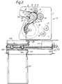
- Figure 2 is a side view of the apparatus shown in Figure 1 illustrating the components in more detail;
- Figure 3 is a partial cross-section through part of the sheet sensing apparatus with parts omitted for clarity;
- Figure 4 is a section taken on the line A-A in Figure 3;
- Figure 5 is a block diagram of the circuit for operating the sheet sensing apparatus shown in Figure 2;
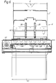
- Figure 6 is a front elevation of the apparatus with parts of the sheet sensing apparatus omitted for clarity;
- Figures 7A-7D illustrate the use of a controlled drop cassette;
- Figure 8 is a block diagram of the control system; and,
- Figures 9 and 10 are views similar to Figure 2 but with parts omitted for clarity showing a second example of the apparatus.
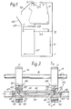
- The apparatus shown in Figures 1-6 is mounted within a steel enclosure 1 and includes a
document feed hopper 2 mounted beneath an inlet opening 3 in the enclosure 1. In this case, the deposit module is mounted to the front of a conventional cash dispenser 19 (not shown). Thehopper 2 forms part of asheet processing apparatus 4 similar to the De La Rue 2520 sheet counter which is described in more detail in EP-A-0168202. - As shown in Figure 2, the
counter 4 comprises a metal housing 1' part of which defines theinput hopper 2. Twoconventional picker wheels 5 are rotatably mounted to the housing 1' and have radially outwardly projectingbosses 6 which, as the picker wheels rotate, periodically protrude through slots in the front of thehopper 2. - A pair of
drive rolls 15 are non-rotatably mounted to adrive shaft 16 which is rotatably mounted to the housing 1. Eachdrive roll 15 has an outerannular portion 17 of rubber. Eachdrive roll 15 contacts a respectiveauxiliary roll 18 rotatably mounted on ashaft 14. - A pair of
stripper rollers 19 are rotatably mounted on a shaft 20 having a larger diameter than theshaft 16 about which it is positioned. The shaft 20 is secured between a pair ofarms 21 of acradle 22. Thecradle 22 is rotatably mounted to anauxiliary drive shaft 23 on which thepicker wheels 5 are mounted. Thecradle 22 has acam portion 24 which engages acam 25 rotatably mounted on the housing 1'. Manual rotation of thecam 25 forces thestripper rollers 19 towards theseparation rollers 10 to define gaps of controlled width. - Removable guiding 7 having a
curved guide surface 8 extends partly around the circumference of therollers shaft 11 supported betweenlugs 9. - A drive motor 30 (shown schematically in Figure 2) continuously drives the
drive shaft 16 via adrive belt 31. The connection between thedrive belt 31 and thedrive shaft 16 has been omitted for clarity. Theauxiliary drive shaft 23 is driven via adrive belt 32 by adrive motor 33 and is connected by a drive belt (not shown) to thestripper roller 19. - A guide plate 34 extends from adjacent the nips formed between the drive rolls 15 and auxiliary rolls 18 to a
conventional stacker wheel 35 rotatably mounted on the housing 1'. - The drive rolls 15 and auxiliary rolls 18 define sheet sensing apparatus for detecting the passage of two or more notes simultaneously and for counting banknotes. The drive rollers and auxiliary rolls are spaced apart by a distance less than the width of sheets being counted.
- The
shaft 14 is hollow, and is non-rotatably supported by the housing 1', and carries the two auxiliary rolls orroller assemblies 18. These are identical in construction and each contacts a respective one of the drive rolls 15. - Each
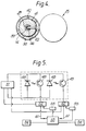
roller assembly 18 comprises a roller bearing having an annular outer race 38 (Figures 3 and 4), an annularinner race 39 andbearings 40 positioned between the inner and outer races. The bearing is mounted coaxially about theshaft 14 on anannular rubber portion 41. Ametal pin 42 abuts the radially inner surface of theinner race 39 and extends through therubber portion 41 and anaperture 43 in theshaft 14 into the shaft. - A moulded
plastics housing 44 is mounted within theshaft 14 and comprises a centraltubular portion 45 integral withend portions 46 each of which has abore 47 communicating with thetubular portion 45. A pair oflight emitting diodes 48 are mounted in the inner ends of thebores 47 while a pair ofphototransistors 49 are mounted at the outer ends of thebores 47. For clarity, only portions of the connecting wires from thelight emitting diodes 48 and thephototransistors 49 have been illustrated. In fact, these wires will pass along and out of theshaft 14 to monitoring circuitry to be described below and to facilitate assembly, all wires extend from the same end of the shaft. Eachportion 46 of thehousing 44 also has anaperture 50 communicating with thebore 47 and in alignment with theaperture 32. Thepins 42 extend through theapertures 50 into thebores 47. - The circuitry is illustrated in more detail in Figure 5. Figure 5 illustrates the two
light emitting diodes 48 and thephototransistors 49 each of which is connected to apower source 51. The section of the circuit shown enclosed in dashed lines is that section mounted in theplastics housing 44. The output from eachphototransistor 49 is fed via respective amplifiers and A/D converters 52 to amicrocomputer 53 which constitutes the main controller for the counter. - Initially, the drive rolls 15 are rotated and with no sheet present between the drive rolls 15 and
roller assemblies 18, any deflection of eachroller assembly 18 accompanied by compression of respectiveresilient portions 41 adjacent the drive rolls 15 will be sensed typically at forty equally spaced intervals through one revolution of theroller assemblies 18. Compression of eachrubber portion 41 in a radially inward direction will be accompanied by radially inward movement of eachpin 42. EachLED 48 continuously emits light which impinges onrespective phototransistors 49 causing them normally to be partially switched on. If apin 42 moves radially inwardly, thepin 42 will increasingly obscure the path of optical rays from the LED's to thephototransistors 49 thus increasing the amount by which thephototransistors 49 are cut off. The output from thephototransistors 49 is fed via the amplifiers and A toD converters 52 to themicroprocessor 53. Themicrocomputer 53 generates an error signal which is fed back to theamplifiers 52 via D to Aconverters 55 to bring the signal back to a reference value. This is done at forty equally spaced sampling positions around the drive rolls 15 (which will be determined by monitoring a timing disc (not shown) mounted non-rotatably to the shaft 16). This produces forty sampled voltage values which are then stored inrespective memories 54 as a guide surface profile or datum level. A similar system is explained in more detail in EP-A-0168202. - In use, a stack of banknotes is placed in the
input hopper 4. Thedrive motors drive shaft 16 and theauxiliary drive shaft 23 rotate. Rotation of thepicker wheels 5 causes banknotes at the bottom of the stack to be urged towards anip 38 between thestripper rollers 19 and theseparation rollers 10. As thestripper rollers 19 rotate in response to the rotation of theauxiliary drive shaft 23, they will engage the adjacent note and carry this note past theguide surface 8 and into thenip 58 formed between the auxiliary rolls 18 and drive rolls 15. The width of the gaps between thestripper rollers 19 andseparation rollers 10 will prevent more than one note being fed by thestripper rollers 19. The note will be fed between the drive rolls 15 and the auxiliary rolls 18 due to the continuous rotation of theshaft 16, the note being fed along the guide plate 34 into thestacker wheel 35 which is being rotated by thedrive motor 30 and which will stack the note fed in the output hopper 37. - As the note passes between the drive rolls 15 and the auxiliary rolls 18, the corresponding
rubber portions 41 will be compressed with accompanying radially inward movement of eachpin 42. This will cause a variation in the light received by thephototransistors 49 which is monitored at the same forty sampling positions. The monitored values are then compared with the previously stored datum and the difference compared with a threshold to indicate whether or not the thickness of the note is greater than the threshold thus indicating whether or not the note is valid. - Other types of monitoring system could be provided including for example an optical system.
- The
counter 4 thus counts the notes and also monitors the length in the feed direction of the notes, the notes then being stacked by the pair ofconventional stacker wheels 35 on astacker tray 105 forming an escrow store. Thetray 105 is accessible by the bank Teller via a secure,escrow door 106 which is transparent to enable the contents on thetray 105 to be viewed. - The
stacker tray 105 is positioned above atamper indicating cassette 107 mounted on a supportingchassis 108. Thetray 105 is slidable to the right, as seen in Figure 1 from underneath a stack of notes which are then allowed to fall into thecassette 107. - Movement of the
tray 105 is controlled by amotor 117 coupled viapulleys 122 to alead screw 123 journalled inbearings 124 beneath thesheet processing apparatus 134. Thelead screw 123 is coupled vianuts 125 to thetray 105 so that when the lead screw is rotated by themotor 117, thetray 105 is drawn to the right, as seen in Figure 2. A set of dependingfingers 126 extend downwardly to a position adjacent the top of thetray 105 so that as the tray is drawn beneath the fingers, any sheets stacked on the tray will be pushed off and allowed to drop into thecassette 107. Sensors (not shown) are provided to ensure the cassette is properly inserted and not full. - In the example just described, the sheets simply fall into the
cassette 107. In an alternative example (Figure 7) a "controlled drop cassette" 107' may be used which contains amovable floor 130 on which sheets are stacked. In this example, a stack ofsheets 131 is loaded onto thetray 105 which remains in position until thefloor 130 has been moved upwardly (by a means not shown) until an existing stack 132 on thefloor 130 is sensed by asensor 133 to be substantially in alignment with the top of the cassette 107'. (This is shown in Figure 7A). Thetray 105 is then drawn away (Figure 7B) allowing thestack 131 to drop by a very short distance onto the top of preexisting stack 132 on thefloor 130. Thefloor 130 is then lowered to its rest position detected by a sensor 134 (Figures 7C and 7D) and thetray 105 is returned to its stacking position. - Operation of the apparatus is controlled by a microprocessor 110 (Figure 8) mounted on a PCB 111 (Figure 1).
- The
microprocessor 110 is connected to akeypad 112 positioned on an outwardly facing surface of the enclosure 1 to enable the operator to input information to themicroprocessor 110. A display is also associated with thekeypad 112 to display information as described below. - The
microprocessor 110 is also coupled to the sheet detector within theapparatus 4, and to thedrive motors apparatus 4. Control of the counter (apparatus 4) is a function of thecounter microprocessor 53 which operates upon receiving commands from themicroprocessor 110 and reports back data such as the number of documents of each specific type and/or dimensions based upon parameters specified by themicroprocessor 110. - A door position detector 115 (not shown in Figure 1) is provided to detect whether or not the
door 106 is in its closed position, the detector being coupled with themicroprocessor 110. Themicroprocessor 110 can also control a lock (not shown) for thedoor 106 via acontrol unit 116. - The position of the
floor 109 of theescrow store 105 is controlled by themicroprocessor 110 via afloor drive unit 117 while a sheet detector 118 (only shown in Figure 8) is positioned within theescrow store 105 to detect the presence of sheets in the store. - In operation, a customer will hand the bank teller a number of bank notes he wishes to deposit. These banknotes will be of a type which the apparatus expects, for example a selection of sterling banknotes. Once the stack has been loaded in the
hopper 2 through the inlet 3, the bank Teller presses a start button on thekeypad 112 which causes themicroprocessor 110 to commence the feed operation of theapparatus 4. This involves commanding themicrocomputer 53 to activate thetransport motor 30 and thestripper motor 33 so that single sheets are fed from thehopper 2 through the detection system and are then stacked in theescrow store 105. The detection system, as explained above, counts the notes and checks their singularity and themicroprocessor 53 attempts to identify the notes by denomination using conventional methods such as long edge size, short edge size, ultraviolet or magnetic properties. If a document cannot be identified then the operator is promted to enter the value. The operator may view the note through the clear section of thedoor 106. - Once all the notes have been fed into the
escrow store 105, themicroprocessor 110 displays on thedisplay 112 the total value of the notes which it believes are within thestore 105. The notes can be seen through the (transparent e.g. clear plastics)door 106. At this time, the Bank Teller presses a "hold" button on the keypad which prevents any further sheets being fed from thehopper 2 but, at this stage, does not permit thefloor 109 to be moved. - If the customer does not agree with the displayed total then the Bank Teller opens the
door 106 and manually removes the stack of notes. Thedoor 106 is then closed. As soon as thedoor position detector 115 detects that thedoor 106 has been opened, this information is passed to themicroprocessor 110 which cancels the transaction and will not permit thefloor 109 to be moved. - Once the customer has agreed that the correct total value for the notes he wishes to deposit is indicated, the Bank Teller presses the "hold" key on the
keypad 112 again causing themicroprocessor 110 to activate thedoor lock control 116 to lock thedoor 106 in its closed position preventing further access to theescrow store 105 from outside the apparatus and thereafter to activate thefloor drive 117 to move thefloor 109 to the right, as seen in Figure 1. The sheets then pass into thecassette 107. In one example, as soon as theescrow detector 118 cannot detect that there are any sheets left in theescrow store 105, thefloor 109 is driven back to its initial position and the operation is completed. In the preferred example, theescrow floor 109 is drawn fully to the right before it is moved back to its initial position. It is "assumed" this action results in all the notes entering thecassette 107. When the floor has returned to its initial position, theescrow detector 118 is used to determine that no notes have been left on theescrow floor 109. Optical sensors (not shown) are used to monitor and control the position of theescrow floor 109. Ifdetector 118 senses that notes have remained on theescrow floor 109, thecustomer access door 106 remains locked until a supervised recovery routine has been completed. At this point, theescrow door 106 is unlocked and the feeding of further notes from thehopper 2 is permitted. - It will be understood that the banknotes placed in the
hopper 2 could be all of the same denomination or of different denominations providing all denominations are expected by the apparatus. - In the case of cheques or badly damaged notes which cannot be automatically read, then the teller will need to enter the fact that these are being processed via the
keypad 112. Cheque values can be entered via ahost computer 120 to which themicroprocessor 110 is connected. Cheque values could also be entered via an enhanced version of thekeypad 112. The host computer also receives data for accounting purposes from themicroprocessor 110. - A second example of a deposit system is shown in Figures 9 and 10. In this case, two cassettes 107,136 are provided beneath the
sheet processing apparatus 4. The construction of the apparatus for the purposes of loading sheets into thecassette 107 is the same as in the Figure 1 example and will not be described in further detail. In order to move stacked sheets into thecassette 136, anadditional frame 137 is slidably mounted to the apparatus for movement between a position overlying the cassette 107 (see Figure 9) and a position overlying the cassette 136 (Figure 10). Theframe 137 has no base so that when positioned above thecassette 107, movement of thetray 105 will allow sheets to drop into thecassette 107 as before. Theframe 137 is driven by aseparate lead screw 138, positioned laterally offset from thelead screw 123, and motor (not shown) in a similar way to thetray 105 and as it is drawn to the right, as seen in Figure 9, it will carry with it any sheets stacked on thetray 105 so that they overlie thecassette 136 into which they will drop since there is no floor at that position.
Claims (9)
- Document deposit apparatus comprising a document inlet (2) into which documents to be deposited are inserted; processing means (15,18) for monitoring at least for the presence of a document; transport means (15,18,19) for transporting documents from the document inlet (2) through the processing means; a temporary store (105) to which the documents from the processing means are fed by the transport means, the temporary store being accessible to a user from outside the apparatus through an access door (106); and control means (110) for indicating to the user the contents of the temporary store and, when the user agrees with the contents, for passing the documents in the temporary store to a deposit region, characterised in that the transport means (15,18,19) feeds all documents passing through the processing means to the same temporary store (105).
- Apparatus according to claim 1, wherein the access door (106) is normally closed, the apparatus further comprising a lock operable by the control means (110) to lock the door in its closed position at least after a user has agreed the contents of the temporary store.
- Apparatus according to claim 1 or claim 2, wherein at least part of the access door (106) is transparent to enable the contents of the temporary store (105) to be viewed.
- Apparatus according to any of the preceding claims, wherein the temporary store (105) is positioned above the deposit region.
- Apparatus according to claim 4, wherein the floor (109) of the temporary store (105) is movable from underneath documents in the temporary store to allow the documents to drop under gravity into the deposit region.
- Apparatus according to any of the preceding claims, further comprising a second deposit region (136), the control means being operable to move documents in the temporary store to either the first or the second deposit region.
- Apparatus according to claim 6, further comprising a slidable frame (137) for sliding documents in the temporary store (105) across its floor (109) to the second deposit region (136).
- Apparatus according to any of the preceding claims, further comprising a document detector for detecting the presence of documents in the temporary store (107).
- A method of operating document deposit apparatus according to any of the preceding claims, the method comprising supplying at least one document to the document inlet, the or each document then being transported to the temporary store, the step of agreeing the contents of the temporary store including the step of the operator supplying to the control means a value constituting an operator determined value for the document(s).
Applications Claiming Priority (2)
| Application Number | Priority Date | Filing Date | Title |
|---|---|---|---|
| GB9303601 | 1993-02-23 | ||
| GB939303601A GB9303601D0 (en) | 1993-02-23 | 1993-02-23 | Document deposit apparatus |
Publications (2)
| Publication Number | Publication Date |
|---|---|
| EP0613107A1 true EP0613107A1 (en) | 1994-08-31 |
| EP0613107B1 EP0613107B1 (en) | 1998-04-29 |
Family
ID=10730883
Family Applications (1)
| Application Number | Title | Priority Date | Filing Date |
|---|---|---|---|
| EP19940301211 Expired - Lifetime EP0613107B1 (en) | 1993-02-23 | 1994-02-21 | Document deposit apparatus |
Country Status (4)
| Country | Link |
|---|---|
| EP (1) | EP0613107B1 (en) |
| DE (1) | DE69409851T2 (en) |
| ES (1) | ES2115877T3 (en) |
| GB (1) | GB9303601D0 (en) |
Cited By (32)
| Publication number | Priority date | Publication date | Assignee | Title |
|---|---|---|---|---|
| EP0731954A1 (en) | 1994-10-04 | 1996-09-18 | Cummins-Allison Corporation | Method and apparatus for discriminating, authenticating and/or counting documents |
| EP0734001A2 (en) * | 1995-03-21 | 1996-09-25 | NCR International, Inc. | Automated depository |
| WO2001067400A2 (en) | 2000-03-10 | 2001-09-13 | De La Rue International Limited | Document evaluation apparatus and method |
| US6363164B1 (en) | 1996-05-13 | 2002-03-26 | Cummins-Allison Corp. | Automated document processing system using full image scanning |
| EP1324287A2 (en) * | 2001-12-20 | 2003-07-02 | Ncr International Inc. | Self service terminal |
| WO2004090817A1 (en) * | 2003-04-09 | 2004-10-21 | Giesecke & Devrient Gmbh | Method and device for processing banknotes |
| WO2007147608A3 (en) * | 2006-06-22 | 2008-03-20 | Giesecke & Devrient Gmbh | Processing device for value documents |
| WO2009100918A1 (en) * | 2008-02-15 | 2009-08-20 | Giesecke & Devrient Gmbh | Method and device for depositing valuable documents |
| US7672499B2 (en) | 1990-02-05 | 2010-03-02 | Cummins-Allison Corp. | Method and apparatus for currency discrimination and counting |
| US7817842B2 (en) | 1994-03-08 | 2010-10-19 | Cummins-Allison Corp. | Method and apparatus for discriminating and counting documents |
| US7881519B2 (en) | 2001-09-27 | 2011-02-01 | Cummins-Allison Corp. | Document processing system using full image scanning |
| US7903863B2 (en) | 2001-09-27 | 2011-03-08 | Cummins-Allison Corp. | Currency bill tracking system |
| US8126793B2 (en) | 2001-07-05 | 2012-02-28 | Cummins-Allison Corp. | Automated payment system and method |
| US8162125B1 (en) | 1996-05-29 | 2012-04-24 | Cummins-Allison Corp. | Apparatus and system for imaging currency bills and financial documents and method for using the same |
| US8169602B2 (en) | 1996-11-27 | 2012-05-01 | Cummins-Allison Corp. | Automated document processing system and method |
| US8204293B2 (en) | 2007-03-09 | 2012-06-19 | Cummins-Allison Corp. | Document imaging and processing system |
| US8391583B1 (en) | 2009-04-15 | 2013-03-05 | Cummins-Allison Corp. | Apparatus and system for imaging currency bills and financial documents and method for using the same |
| US8417017B1 (en) | 2007-03-09 | 2013-04-09 | Cummins-Allison Corp. | Apparatus and system for imaging currency bills and financial documents and method for using the same |
| US8428332B1 (en) | 2001-09-27 | 2013-04-23 | Cummins-Allison Corp. | Apparatus and system for imaging currency bills and financial documents and method for using the same |
| US8433123B1 (en) | 2001-09-27 | 2013-04-30 | Cummins-Allison Corp. | Apparatus and system for imaging currency bills and financial documents and method for using the same |
| US8437528B1 (en) | 2009-04-15 | 2013-05-07 | Cummins-Allison Corp. | Apparatus and system for imaging currency bills and financial documents and method for using the same |
| US8437530B1 (en) | 2001-09-27 | 2013-05-07 | Cummins-Allison Corp. | Apparatus and system for imaging currency bills and financial documents and method for using the same |
| US8437529B1 (en) | 2001-09-27 | 2013-05-07 | Cummins-Allison Corp. | Apparatus and system for imaging currency bills and financial documents and method for using the same |
| US8459436B2 (en) | 2008-10-29 | 2013-06-11 | Cummins-Allison Corp. | System and method for processing currency bills and tickets |
| US8478020B1 (en) | 1996-11-27 | 2013-07-02 | Cummins-Allison Corp. | Apparatus and system for imaging currency bills and financial documents and method for using the same |
| US8538123B1 (en) | 2007-03-09 | 2013-09-17 | Cummins-Allison Corp. | Apparatus and system for imaging currency bills and financial documents and method for using the same |
| US8627939B1 (en) | 2002-09-25 | 2014-01-14 | Cummins-Allison Corp. | Apparatus and system for imaging currency bills and financial documents and method for using the same |
| US8929640B1 (en) | 2009-04-15 | 2015-01-06 | Cummins-Allison Corp. | Apparatus and system for imaging currency bills and financial documents and method for using the same |
| US8944234B1 (en) | 2001-09-27 | 2015-02-03 | Cummins-Allison Corp. | Apparatus and system for imaging currency bills and financial documents and method for using the same |
| US9141876B1 (en) | 2013-02-22 | 2015-09-22 | Cummins-Allison Corp. | Apparatus and system for processing currency bills and financial documents and method for using the same |
| CN107004140A (en) * | 2014-12-05 | 2017-08-01 | 星球智能有限责任公司 | Text recognition method and computer program product |
| US9818249B1 (en) | 2002-09-04 | 2017-11-14 | Copilot Ventures Fund Iii Llc | Authentication method and system |
Families Citing this family (10)
| Publication number | Priority date | Publication date | Assignee | Title |
|---|---|---|---|---|
| US5790697A (en) | 1990-02-05 | 1998-08-04 | Cummins-Allion Corp. | Method and apparatus for discriminating and counting documents |
| US6636624B2 (en) | 1990-02-05 | 2003-10-21 | Cummins-Allison Corp. | Method and apparatus for currency discrimination and counting |
| US6748101B1 (en) | 1995-05-02 | 2004-06-08 | Cummins-Allison Corp. | Automatic currency processing system |
| US8443958B2 (en) | 1996-05-13 | 2013-05-21 | Cummins-Allison Corp. | Apparatus, system and method for coin exchange |
| US6661910B2 (en) | 1997-04-14 | 2003-12-09 | Cummins-Allison Corp. | Network for transporting and processing images in real time |
| DE10121835A1 (en) * | 2001-05-04 | 2002-11-07 | Giesecke & Devrient Gmbh | Device and method for entering and depositing banknotes |
| US6896118B2 (en) | 2002-01-10 | 2005-05-24 | Cummins-Allison Corp. | Coin redemption system |
| US7946406B2 (en) | 2005-11-12 | 2011-05-24 | Cummins-Allison Corp. | Coin processing device having a moveable coin receptacle station |
| US7980378B2 (en) | 2006-03-23 | 2011-07-19 | Cummins-Allison Corporation | Systems, apparatus, and methods for currency processing control and redemption |
| US7929749B1 (en) | 2006-09-25 | 2011-04-19 | Cummins-Allison Corp. | System and method for saving statistical data of currency bills in a currency processing device |
Citations (6)
| Publication number | Priority date | Publication date | Assignee | Title |
|---|---|---|---|---|
| US3064785A (en) * | 1962-11-20 | weingart | ||
| US3765523A (en) * | 1970-02-13 | 1973-10-16 | Omron Tateisi Electronics Co | Paper money receiving apparatus |
| DE2600963A1 (en) * | 1975-01-14 | 1976-07-15 | Laurel Bank Machine Co | DEVICE FOR TREATMENT OF PAPER AND OTHER LIGHT FLATS |
| CH590525A5 (en) * | 1975-07-24 | 1977-08-15 | Inpat Sa | Automatic banknote controlled vending machine - notes drop after checking into locked compartment opened to return or drop note into safe |
| GB2073718A (en) * | 1980-04-15 | 1981-10-21 | Laurel Bank Machine Co | Bank note depositing apparatus |
| US4889220A (en) * | 1986-08-06 | 1989-12-26 | Oki Electric Industry Co., Ltd. | Automatic money depositing apparatus |
-
1993
- 1993-02-23 GB GB939303601A patent/GB9303601D0/en active Pending
-
1994
- 1994-02-21 ES ES94301211T patent/ES2115877T3/en not_active Expired - Lifetime
- 1994-02-21 DE DE1994609851 patent/DE69409851T2/en not_active Expired - Fee Related
- 1994-02-21 EP EP19940301211 patent/EP0613107B1/en not_active Expired - Lifetime
Patent Citations (6)
| Publication number | Priority date | Publication date | Assignee | Title |
|---|---|---|---|---|
| US3064785A (en) * | 1962-11-20 | weingart | ||
| US3765523A (en) * | 1970-02-13 | 1973-10-16 | Omron Tateisi Electronics Co | Paper money receiving apparatus |
| DE2600963A1 (en) * | 1975-01-14 | 1976-07-15 | Laurel Bank Machine Co | DEVICE FOR TREATMENT OF PAPER AND OTHER LIGHT FLATS |
| CH590525A5 (en) * | 1975-07-24 | 1977-08-15 | Inpat Sa | Automatic banknote controlled vending machine - notes drop after checking into locked compartment opened to return or drop note into safe |
| GB2073718A (en) * | 1980-04-15 | 1981-10-21 | Laurel Bank Machine Co | Bank note depositing apparatus |
| US4889220A (en) * | 1986-08-06 | 1989-12-26 | Oki Electric Industry Co., Ltd. | Automatic money depositing apparatus |
Non-Patent Citations (1)
| Title |
|---|
| DATABASE WPI Week 7736, Derwent World Patents Index; AN 77-H3507Y * |
Cited By (90)
| Publication number | Priority date | Publication date | Assignee | Title |
|---|---|---|---|---|
| US7672499B2 (en) | 1990-02-05 | 2010-03-02 | Cummins-Allison Corp. | Method and apparatus for currency discrimination and counting |
| US7817842B2 (en) | 1994-03-08 | 2010-10-19 | Cummins-Allison Corp. | Method and apparatus for discriminating and counting documents |
| EP1246139A3 (en) * | 1994-10-04 | 2006-11-15 | Cummins-Allison Corporation | Method and apparatus for discriminating, authenticating and/or counting documents |
| EP1246139A2 (en) * | 1994-10-04 | 2002-10-02 | Cummins-Allison Corporation | Method and apparatus for discriminating, authenticating and/or counting documents |
| EP0731954A1 (en) | 1994-10-04 | 1996-09-18 | Cummins-Allison Corporation | Method and apparatus for discriminating, authenticating and/or counting documents |
| EP0734001A2 (en) * | 1995-03-21 | 1996-09-25 | NCR International, Inc. | Automated depository |
| EP0734001A3 (en) * | 1995-03-21 | 2002-10-02 | NCR International, Inc. | Automated depository |
| US6647136B2 (en) | 1996-05-13 | 2003-11-11 | Cummins-Allison Corp. | Automated check processing system and method |
| US6724926B2 (en) | 1996-05-13 | 2004-04-20 | Cummins-Allison Corp. | Networked automated document processing system and method |
| US6650767B2 (en) | 1996-05-13 | 2003-11-18 | Cummins-Allison, Corp. | Automated deposit processing system and method |
| US6654486B2 (en) | 1996-05-13 | 2003-11-25 | Cummins-Allison Corp. | Automated document processing system |
| US6363164B1 (en) | 1996-05-13 | 2002-03-26 | Cummins-Allison Corp. | Automated document processing system using full image scanning |
| US6665431B2 (en) | 1996-05-13 | 2003-12-16 | Cummins-Allison Corp. | Automated document processing system using full image scanning |
| US6678401B2 (en) | 1996-05-13 | 2004-01-13 | Cummins-Allison Corp. | Automated currency processing system |
| US6678402B2 (en) | 1996-05-13 | 2004-01-13 | Cummins-Allison Corp. | Automated document processing system using full image scanning |
| US6724927B2 (en) | 1996-05-13 | 2004-04-20 | Cummins-Allison Corp. | Automated document processing system with document imaging and value indication |
| US6603872B2 (en) | 1996-05-13 | 2003-08-05 | Cummins-Allison Corp. | Automated document processing system using full image scanning |
| US6731786B2 (en) | 1996-05-13 | 2004-05-04 | Cummins-Allison Corp. | Document processing method and system |
| US6810137B2 (en) | 1996-05-13 | 2004-10-26 | Cummins-Allison Corp. | Automated document processing system and method |
| US8714336B2 (en) | 1996-05-29 | 2014-05-06 | Cummins-Allison Corp. | Apparatus and system for imaging currency bills and financial documents and method for using the same |
| US8162125B1 (en) | 1996-05-29 | 2012-04-24 | Cummins-Allison Corp. | Apparatus and system for imaging currency bills and financial documents and method for using the same |
| US8437531B2 (en) | 1996-11-27 | 2013-05-07 | Cummins-Allison Corp. | Check and U.S. bank note processing device and method |
| US9390574B2 (en) | 1996-11-27 | 2016-07-12 | Cummins-Allison Corp. | Document processing system |
| US8339589B2 (en) | 1996-11-27 | 2012-12-25 | Cummins-Allison Corp. | Check and U.S. bank note processing device and method |
| US8478020B1 (en) | 1996-11-27 | 2013-07-02 | Cummins-Allison Corp. | Apparatus and system for imaging currency bills and financial documents and method for using the same |
| US8442296B2 (en) | 1996-11-27 | 2013-05-14 | Cummins-Allison Corp. | Check and U.S. bank note processing device and method |
| US8169602B2 (en) | 1996-11-27 | 2012-05-01 | Cummins-Allison Corp. | Automated document processing system and method |
| US8701857B2 (en) | 2000-02-11 | 2014-04-22 | Cummins-Allison Corp. | System and method for processing currency bills and tickets |
| US9495808B2 (en) | 2000-02-11 | 2016-11-15 | Cummins-Allison Corp. | System and method for processing casino tickets |
| US9129271B2 (en) | 2000-02-11 | 2015-09-08 | Cummins-Allison Corp. | System and method for processing casino tickets |
| WO2001067400A2 (en) | 2000-03-10 | 2001-09-13 | De La Rue International Limited | Document evaluation apparatus and method |
| US8126793B2 (en) | 2001-07-05 | 2012-02-28 | Cummins-Allison Corp. | Automated payment system and method |
| US7881519B2 (en) | 2001-09-27 | 2011-02-01 | Cummins-Allison Corp. | Document processing system using full image scanning |
| US8644585B1 (en) | 2001-09-27 | 2014-02-04 | Cummins-Allison Corp. | Apparatus and system for imaging currency bills and financial documents and method for using the same |
| US8041098B2 (en) | 2001-09-27 | 2011-10-18 | Cummins-Allison Corp. | Document processing system using full image scanning |
| US8639015B1 (en) | 2001-09-27 | 2014-01-28 | Cummins-Allison Corp. | Apparatus and system for imaging currency bills and financial documents and method for using the same |
| US7903863B2 (en) | 2001-09-27 | 2011-03-08 | Cummins-Allison Corp. | Currency bill tracking system |
| US9142075B1 (en) | 2001-09-27 | 2015-09-22 | Cummins-Allison Corp. | Apparatus and system for imaging currency bills and financial documents and method for using the same |
| US8396278B2 (en) | 2001-09-27 | 2013-03-12 | Cummins-Allison Corp. | Document processing system using full image scanning |
| US8103084B2 (en) | 2001-09-27 | 2012-01-24 | Cummins-Allison Corp. | Document processing system using full image scanning |
| US8944234B1 (en) | 2001-09-27 | 2015-02-03 | Cummins-Allison Corp. | Apparatus and system for imaging currency bills and financial documents and method for using the same |
| US8428332B1 (en) | 2001-09-27 | 2013-04-23 | Cummins-Allison Corp. | Apparatus and system for imaging currency bills and financial documents and method for using the same |
| US8433123B1 (en) | 2001-09-27 | 2013-04-30 | Cummins-Allison Corp. | Apparatus and system for imaging currency bills and financial documents and method for using the same |
| US8644584B1 (en) | 2001-09-27 | 2014-02-04 | Cummins-Allison Corp. | Apparatus and system for imaging currency bills and financial documents and method for using the same |
| US8437530B1 (en) | 2001-09-27 | 2013-05-07 | Cummins-Allison Corp. | Apparatus and system for imaging currency bills and financial documents and method for using the same |
| US8655046B1 (en) | 2001-09-27 | 2014-02-18 | Cummins-Allison Corp. | Apparatus and system for imaging currency bills and financial documents and method for using the same |
| US8437529B1 (en) | 2001-09-27 | 2013-05-07 | Cummins-Allison Corp. | Apparatus and system for imaging currency bills and financial documents and method for using the same |
| US8655045B2 (en) | 2001-09-27 | 2014-02-18 | Cummins-Allison Corp. | System and method for processing a deposit transaction |
| US6663001B2 (en) | 2001-12-20 | 2003-12-16 | Ncr Corporation | Self service terminal |
| EP1324287A3 (en) * | 2001-12-20 | 2006-01-11 | Ncr International Inc. | Self service terminal |
| EP1324287A2 (en) * | 2001-12-20 | 2003-07-02 | Ncr International Inc. | Self service terminal |
| US9818249B1 (en) | 2002-09-04 | 2017-11-14 | Copilot Ventures Fund Iii Llc | Authentication method and system |
| US8627939B1 (en) | 2002-09-25 | 2014-01-14 | Cummins-Allison Corp. | Apparatus and system for imaging currency bills and financial documents and method for using the same |
| US9355295B1 (en) | 2002-09-25 | 2016-05-31 | Cummins-Allison Corp. | Apparatus and system for imaging currency bills and financial documents and method for using the same |
| WO2004090817A1 (en) * | 2003-04-09 | 2004-10-21 | Giesecke & Devrient Gmbh | Method and device for processing banknotes |
| WO2007147608A3 (en) * | 2006-06-22 | 2008-03-20 | Giesecke & Devrient Gmbh | Processing device for value documents |
| US7954700B2 (en) | 2006-06-22 | 2011-06-07 | Giesecke & Devrient Gmbh | Processing device for value documents |
| CN101473357B (en) * | 2006-06-22 | 2012-03-14 | 德国捷德有限公司 | Processing device for value documents |
| US8403206B2 (en) | 2006-06-22 | 2013-03-26 | Giesecke & Devrient Gmbh | Processing device for documents of value |
| US8417017B1 (en) | 2007-03-09 | 2013-04-09 | Cummins-Allison Corp. | Apparatus and system for imaging currency bills and financial documents and method for using the same |
| US8538123B1 (en) | 2007-03-09 | 2013-09-17 | Cummins-Allison Corp. | Apparatus and system for imaging currency bills and financial documents and method for using the same |
| US8542904B1 (en) | 2007-03-09 | 2013-09-24 | Cummins-Allison Corp. | Apparatus and system for imaging currency bills and financial documents and method for using the same |
| US8625875B2 (en) | 2007-03-09 | 2014-01-07 | Cummins-Allison Corp. | Document imaging and processing system for performing blind balancing and display conditions |
| US8204293B2 (en) | 2007-03-09 | 2012-06-19 | Cummins-Allison Corp. | Document imaging and processing system |
| WO2009100918A1 (en) * | 2008-02-15 | 2009-08-20 | Giesecke & Devrient Gmbh | Method and device for depositing valuable documents |
| US8459436B2 (en) | 2008-10-29 | 2013-06-11 | Cummins-Allison Corp. | System and method for processing currency bills and tickets |
| US8594414B1 (en) | 2009-04-15 | 2013-11-26 | Cummins-Allison Corp. | Apparatus and system for imaging currency bills and financial documents and method for using the same |
| US8437532B1 (en) | 2009-04-15 | 2013-05-07 | Cummins-Allison Corp. | Apparatus and system for imaging currency bills and financial documents and method for using the same |
| US8929640B1 (en) | 2009-04-15 | 2015-01-06 | Cummins-Allison Corp. | Apparatus and system for imaging currency bills and financial documents and method for using the same |
| US8948490B1 (en) | 2009-04-15 | 2015-02-03 | Cummins-Allison Corp. | Apparatus and system for imaging currency bills and financial documents and method for using the same |
| US8437528B1 (en) | 2009-04-15 | 2013-05-07 | Cummins-Allison Corp. | Apparatus and system for imaging currency bills and financial documents and method for using the same |
| US8958626B1 (en) | 2009-04-15 | 2015-02-17 | Cummins-Allison Corp. | Apparatus and system for imaging currency bills and financial documents and method for using the same |
| US8559695B1 (en) | 2009-04-15 | 2013-10-15 | Cummins-Allison Corp. | Apparatus and system for imaging currency bills and financial documents and method for using the same |
| US10452906B1 (en) | 2009-04-15 | 2019-10-22 | Cummins-Allison Corp. | Apparatus and system for imaging currency bills and financial documents and method for using the same |
| US8391583B1 (en) | 2009-04-15 | 2013-03-05 | Cummins-Allison Corp. | Apparatus and system for imaging currency bills and financial documents and method for using the same |
| US9189780B1 (en) | 2009-04-15 | 2015-11-17 | Cummins-Allison Corp. | Apparatus and system for imaging currency bills and financial documents and methods for using the same |
| US9195889B2 (en) | 2009-04-15 | 2015-11-24 | Cummins-Allison Corp. | System and method for processing banknote and check deposits |
| US8787652B1 (en) | 2009-04-15 | 2014-07-22 | Cummins-Allison Corp. | Apparatus and system for imaging currency bills and financial documents and method for using the same |
| US8467591B1 (en) | 2009-04-15 | 2013-06-18 | Cummins-Allison Corp. | Apparatus and system for imaging currency bills and financial documents and method for using the same |
| US9477896B1 (en) | 2009-04-15 | 2016-10-25 | Cummins-Allison Corp. | Apparatus and system for imaging currency bills and financial documents and method for using the same |
| US8478019B1 (en) | 2009-04-15 | 2013-07-02 | Cummins-Allison Corp. | Apparatus and system for imaging currency bills and financial documents and method for using the same |
| US9971935B1 (en) | 2009-04-15 | 2018-05-15 | Cummins-Allison Corp. | Apparatus and system for imaging currency bills and financial documents and method for using the same |
| US9972156B1 (en) | 2009-04-15 | 2018-05-15 | Cummins-Allison Corp. | Apparatus and system for imaging currency bills and financial documents and method for using the same |
| US8644583B1 (en) | 2009-04-15 | 2014-02-04 | Cummins-Allison Corp. | Apparatus and system for imaging currency bills and financial documents and method for using the same |
| US9558418B2 (en) | 2013-02-22 | 2017-01-31 | Cummins-Allison Corp. | Apparatus and system for processing currency bills and financial documents and method for using the same |
| US10163023B2 (en) | 2013-02-22 | 2018-12-25 | Cummins-Allison Corp. | Apparatus and system for processing currency bills and financial documents and method for using the same |
| US9141876B1 (en) | 2013-02-22 | 2015-09-22 | Cummins-Allison Corp. | Apparatus and system for processing currency bills and financial documents and method for using the same |
| US11314980B1 (en) | 2013-02-22 | 2022-04-26 | Cummins-Allison Corp. | Apparatus and system for processing currency bills and financial documents and method for using the same |
| CN107004140A (en) * | 2014-12-05 | 2017-08-01 | 星球智能有限责任公司 | Text recognition method and computer program product |
| CN107004140B (en) * | 2014-12-05 | 2021-01-12 | 星球智能有限责任公司 | Text recognition method and computer program product |
Also Published As
| Publication number | Publication date |
|---|---|
| GB9303601D0 (en) | 1993-04-07 |
| ES2115877T3 (en) | 1998-07-01 |
| EP0613107B1 (en) | 1998-04-29 |
| DE69409851D1 (en) | 1998-06-04 |
| DE69409851T2 (en) | 1998-09-24 |
Similar Documents
| Publication | Publication Date | Title |
|---|---|---|
| EP0613107B1 (en) | Document deposit apparatus | |
| EP1034126B1 (en) | Document sensor for currency recycling automated banking machine | |
| JP4135238B2 (en) | Banknote deposit and withdrawal machine | |
| US6290070B1 (en) | Currency recycling automated banking machine | |
| US6318714B1 (en) | Document unstack system for currency recycling automated banking machine | |
| EP1034125B1 (en) | Document alignment mechanism for currency recycling automated banking machine | |
| EP1086036B1 (en) | Automated banking machine with currency recycling canisters | |
| EP2110792B1 (en) | Sheets processing machine | |
| EP0616963A2 (en) | Sheet handling apparatus | |
| CA2305292C (en) | Currency recycling automated banking machine media gate | |
| US4889220A (en) | Automatic money depositing apparatus | |
| US4874931A (en) | Method for automatic bill handling and bill container used therefor | |
| JP4292180B2 (en) | Automatic transaction equipment | |
| US5988634A (en) | Apparatus for detecting the passage of multiple superposed sheets along a feed path | |
| JPH0323465B2 (en) | ||
| RU2189345C2 (en) | Device and method for checking thickness of bank note for electronic currency recycling machine | |
| JP4310304B2 (en) | Automatic transaction equipment | |
| JPH04446Y2 (en) | ||
| WO2001067400A2 (en) | Document evaluation apparatus and method | |
| MXPA00004875A (en) | Document sensor for currency recycling automated banking machine | |
| JPH01310497A (en) | Cash dispersing device | |
| WO2002093505A1 (en) | Sheet handling apparatus |
Legal Events
| Date | Code | Title | Description |
|---|---|---|---|
| PUAI | Public reference made under article 153(3) epc to a published international application that has entered the european phase |
Free format text: ORIGINAL CODE: 0009012 |
|
| AK | Designated contracting states |
Kind code of ref document: A1 Designated state(s): CH DE ES FR GB IT LI PT |
|
| 17P | Request for examination filed |
Effective date: 19950224 |
|
| 17Q | First examination report despatched |
Effective date: 19960820 |
|
| GRAG | Despatch of communication of intention to grant |
Free format text: ORIGINAL CODE: EPIDOS AGRA |
|
| GRAG | Despatch of communication of intention to grant |
Free format text: ORIGINAL CODE: EPIDOS AGRA |
|
| GRAH | Despatch of communication of intention to grant a patent |
Free format text: ORIGINAL CODE: EPIDOS IGRA |
|
| GRAG | Despatch of communication of intention to grant |
Free format text: ORIGINAL CODE: EPIDOS AGRA |
|
| GRAG | Despatch of communication of intention to grant |
Free format text: ORIGINAL CODE: EPIDOS AGRA |
|
| RAP1 | Party data changed (applicant data changed or rights of an application transferred) |
Owner name: DE LA RUE CASH HANDLING AB |
|
| GRAH | Despatch of communication of intention to grant a patent |
Free format text: ORIGINAL CODE: EPIDOS IGRA |
|
| GRAA | (expected) grant |
Free format text: ORIGINAL CODE: 0009210 |
|
| RAP1 | Party data changed (applicant data changed or rights of an application transferred) |
Owner name: DE LA RUE CASH SYSTEMS AKTIEBOLAG |
|
| AK | Designated contracting states |
Kind code of ref document: B1 Designated state(s): CH DE ES FR GB IT LI PT |
|
| REG | Reference to a national code |
Ref country code: CH Ref legal event code: NV Representative=s name: ISLER & PEDRAZZINI AG Ref country code: CH Ref legal event code: EP |
|
| REF | Corresponds to: |
Ref document number: 69409851 Country of ref document: DE Date of ref document: 19980604 |
|
| REG | Reference to a national code |
Ref country code: ES Ref legal event code: FG2A Ref document number: 2115877 Country of ref document: ES Kind code of ref document: T3 |
|
| ITF | It: translation for a ep patent filed |
Owner name: JACOBACCI & PERANI S.P.A. |
|
| ET | Fr: translation filed | ||
| REG | Reference to a national code |
Ref country code: PT Ref legal event code: SC4A Free format text: AVAILABILITY OF NATIONAL TRANSLATION Effective date: 19980727 |
|
| PLBE | No opposition filed within time limit |
Free format text: ORIGINAL CODE: 0009261 |
|
| STAA | Information on the status of an ep patent application or granted ep patent |
Free format text: STATUS: NO OPPOSITION FILED WITHIN TIME LIMIT |
|
| 26N | No opposition filed | ||
| RAP2 | Party data changed (patent owner data changed or rights of a patent transferred) |
Owner name: DE LA RUE INTERNATIONAL LIMITED |
|
| REG | Reference to a national code |
Ref country code: GB Ref legal event code: 732E |
|
| REG | Reference to a national code |
Ref country code: CH Ref legal event code: PUE Owner name: DE LA RUE CASH SYSTEMS AKTIEBOLAG TRANSFER- DE LA |
|
| REG | Reference to a national code |
Ref country code: GB Ref legal event code: IF02 |
|
| REG | Reference to a national code |
Ref country code: PT Ref legal event code: PC4A Free format text: DE LA RUE INTERNATIONAL LIMITED GB Effective date: 20011130 |
|
| REG | Reference to a national code |
Ref country code: FR Ref legal event code: TP |
|
| PGFP | Annual fee paid to national office [announced via postgrant information from national office to epo] |
Ref country code: FR Payment date: 20030210 Year of fee payment: 10 |
|
| PGFP | Annual fee paid to national office [announced via postgrant information from national office to epo] |
Ref country code: DE Payment date: 20030306 Year of fee payment: 10 |
|
| PG25 | Lapsed in a contracting state [announced via postgrant information from national office to epo] |
Ref country code: GB Free format text: LAPSE BECAUSE OF NON-PAYMENT OF DUE FEES Effective date: 20040221 |
|
| PG25 | Lapsed in a contracting state [announced via postgrant information from national office to epo] |
Ref country code: DE Free format text: LAPSE BECAUSE OF NON-PAYMENT OF DUE FEES Effective date: 20040901 |
|
| GBPC | Gb: european patent ceased through non-payment of renewal fee |
Effective date: 20040221 |
|
| REG | Reference to a national code |
Ref country code: CH Ref legal event code: PL |
|
| PG25 | Lapsed in a contracting state [announced via postgrant information from national office to epo] |
Ref country code: FR Free format text: LAPSE BECAUSE OF NON-PAYMENT OF DUE FEES Effective date: 20041029 |
|
| REG | Reference to a national code |
Ref country code: CH Ref legal event code: AEN Free format text: DAS PATENT IST AUFGRUND DES WEITERBEHANDLUNGSANTRAGS VOM 18.10.2004 REAKTIVIERT WORDEN. |
|
| REG | Reference to a national code |
Ref country code: FR Ref legal event code: ST |
|
| REG | Reference to a national code |
Ref country code: PT Ref legal event code: NF4A Effective date: 19940221 |
|
| REG | Reference to a national code |
Ref country code: GB Ref legal event code: 728V |
|
| REG | Reference to a national code |
Ref country code: GB Ref legal event code: ERR Free format text: APPLICATION FOR RESTORATION FILED |
|
| REG | Reference to a national code |
Ref country code: GB Ref legal event code: 728Y |
|
| REG | Reference to a national code |
Ref country code: CH Ref legal event code: PCAR Free format text: ISLER & PEDRAZZINI AG;POSTFACH 1772;8027 ZUERICH (CH) |
|
| REG | Reference to a national code |
Ref country code: PT Ref legal event code: PC4A Owner name: TALARIS HOLDINGS LIMITED, GB Effective date: 20090211 |
|
| REG | Reference to a national code |
Ref country code: CH Ref legal event code: PUE Owner name: TALARIS HOLDINGS LIMITED Free format text: DE LA RUE INTERNATIONAL LIMITED#DE LA RUE HOUSE, JAYS CLOSE, VIABLES#BASINGSTOKE (HANTS RG22 4BS) (GB) -TRANSFER TO- TALARIS HOLDINGS LIMITED#TALARIS HOUSE CROCKFORD LANE CHINEHAM BUSINESS PARK#BASINGSTOKE, HAMPSHIRE RG24 8QZ (GB) Ref country code: CH Ref legal event code: NV Representative=s name: KELLER & PARTNER PATENTANWAELTE AG |
|
| REG | Reference to a national code |
Ref country code: GB Ref legal event code: 732E Free format text: REGISTERED BETWEEN 20090611 AND 20090617 |
|
| REG | Reference to a national code |
Ref country code: ES Ref legal event code: PC2A |
|
| PGFP | Annual fee paid to national office [announced via postgrant information from national office to epo] |
Ref country code: IT Payment date: 20120224 Year of fee payment: 19 |
|
| PGFP | Annual fee paid to national office [announced via postgrant information from national office to epo] |
Ref country code: CH Payment date: 20130221 Year of fee payment: 20 Ref country code: ES Payment date: 20130221 Year of fee payment: 20 Ref country code: GB Payment date: 20130222 Year of fee payment: 20 |
|
| PGFP | Annual fee paid to national office [announced via postgrant information from national office to epo] |
Ref country code: PT Payment date: 20130213 Year of fee payment: 20 |
|
| REG | Reference to a national code |
Ref country code: CH Ref legal event code: PL Ref country code: PT Ref legal event code: MM4A Free format text: MAXIMUM VALIDITY LIMIT REACHED Effective date: 20140221 |
|
| REG | Reference to a national code |
Ref country code: GB Ref legal event code: PE20 Expiry date: 20140220 |
|
| PG25 | Lapsed in a contracting state [announced via postgrant information from national office to epo] |
Ref country code: GB Free format text: LAPSE BECAUSE OF EXPIRATION OF PROTECTION Effective date: 20140220 |
|
| PG25 | Lapsed in a contracting state [announced via postgrant information from national office to epo] |
Ref country code: PT Free format text: LAPSE BECAUSE OF EXPIRATION OF PROTECTION Effective date: 20140228 |
|
| REG | Reference to a national code |
Ref country code: ES Ref legal event code: FD2A Effective date: 20140925 |
|
| PG25 | Lapsed in a contracting state [announced via postgrant information from national office to epo] |
Ref country code: ES Free format text: LAPSE BECAUSE OF EXPIRATION OF PROTECTION Effective date: 20140222 |