EP0612505A1 - Surgical forceps for applying suture clips - Google Patents
Surgical forceps for applying suture clips Download PDFInfo
- Publication number
- EP0612505A1 EP0612505A1 EP93460004A EP93460004A EP0612505A1 EP 0612505 A1 EP0612505 A1 EP 0612505A1 EP 93460004 A EP93460004 A EP 93460004A EP 93460004 A EP93460004 A EP 93460004A EP 0612505 A1 EP0612505 A1 EP 0612505A1
- Authority
- EP
- European Patent Office
- Prior art keywords
- jaws
- magazine
- slide
- clips
- surgical forceps
- Prior art date
- Legal status (The legal status is an assumption and is not a legal conclusion. Google has not performed a legal analysis and makes no representation as to the accuracy of the status listed.)
- Withdrawn
Links
Images


Classifications
-
- A—HUMAN NECESSITIES
- A61—MEDICAL OR VETERINARY SCIENCE; HYGIENE
- A61B—DIAGNOSIS; SURGERY; IDENTIFICATION
- A61B17/00—Surgical instruments, devices or methods, e.g. tourniquets
- A61B17/12—Surgical instruments, devices or methods, e.g. tourniquets for ligaturing or otherwise compressing tubular parts of the body, e.g. blood vessels, umbilical cord
- A61B17/128—Surgical instruments, devices or methods, e.g. tourniquets for ligaturing or otherwise compressing tubular parts of the body, e.g. blood vessels, umbilical cord for applying or removing clamps or clips
- A61B17/1285—Surgical instruments, devices or methods, e.g. tourniquets for ligaturing or otherwise compressing tubular parts of the body, e.g. blood vessels, umbilical cord for applying or removing clamps or clips for minimally invasive surgery
Definitions
- the present invention relates to surgical forceps for placing suture clips and more specifically clips having the general shape of a "U” which is crimped, by tightening the clip, on blood vessels.
- Surgical instruments of this type are well known. They contain a reserve of clips, for example fifteen or twenty clips. They have operating devices such as scissor branches. Using these branches, the surgeon can place the clip with one hand, the internal mechanisms of the instrument ensuring the distribution of a new clip of the reserve during the maneuver.
- This type of instrument of course sanitized, is generally used only once. It is discarded at the end of the surgical intervention, whether or not the reserve of clips is exhausted.
- the instrument which is the subject of EP-B-170 592 comprises means supporting a row of clips, as well as a means for closing clips which is movable from front to back.
- This means carries a pair of jaws which, as a result of their movement in the distal direction, are brought closer to each other by stationary cam surfaces.
- the instrument comprises an exhaust device arranged to place the last clip of the row between the jaws, when the movable closure means is in the retracted position, and to retain the other clips.
- Such an instrument in addition to its mechanical complexity, is not really satisfactory because of the displacement of the clamping jaws during suturing, which is inconvenient because it causes the displacement of the vessel to be ligated.
- the instrument according to EP-B-144 144 comprises a pair of movable jaws, the actuation of which is carried out by means of the scissor branch type.
- the instrument comprises a pusher means arranged to transfer the clips one by one at a time into the jaws, from storage means receiving the clips one behind the other.
- This device is relatively complex and expensive.
- the device according to FR-A-2 637 489 is also very complex, insofar as this instrument comprises two parts movable in translation and in opposite directions; one of the parts is the store containing the reserve of clips. The other part is a sheath ensuring the closure of the jaws.
- the maneuvering branches, of the scissor type drive two sets of rods, each of these games controlling the movement of one of the two parts.
- the present invention aims to resolve these difficulties by proposing an instrument of the type mentioned above which is reliable in operation, simple to handle, and has a low cost price.
- the object of the invention which is used to place suture clips on blood vessels, these clips having the general shape of a "U", is of the type comprising a fixed body on which two operating levers are articulated, of the scissor branch type, this fixed body containing a linear magazine having an open end and containing a reserve of clips arranged flat against each other, their opening facing the open end, the clamp comprising a pair of jaws located in the extension of the magazine, just at the exit from its open end, these jaws being adapted to retain and to crimp clips one after the other from the magazine.
- the clamp comprises a slide disposed longitudinally above the magazine and whose longitudinal translational movement (that is to say parallel to the longitudinal direction of the magazine) is controlled by the operating levers, the closing of these causing the slide to move in the opposite direction to the open end - direction which in the following will be called “backward” - while their opening causes the slide to move in the opposite direction - direction which will be called “advance” "-;
- the clamp also comprises a thrust spring which constantly tends to move the reserve of clips towards the open end of the magazine, while the slide is integral, on the one hand with means ensuring the closing of the jaws during its recoil, d on the other hand, a retaining tab for the first clip contained (open end side) in the magazine, means ensuring the temporary retraction of this tab during the advance of the slide.
- the surgical forceps 100 shown in Figure 1 - arranged flat, horizontally - has a fixed body 1 having an elongated shape; only its rear end (right part of the figure) has been shown in the drawing.
- a pair of operating levers 4 of the scissor-branch type On the body 1 are articulated, around vertical axes 40, a pair of operating levers 4 of the scissor-branch type, the free ends of which are shaped into rings allowing the passage of the fingers.
- a link 5 On each lever 4 is articulated, around a vertical axis 50, a link 5.
- the two links are articulated, at their opposite end, around an axis 51, on the end of a slide 2.
- the latter has the shape of a rod, which extends longitudinally, coaxially to the fixed body 1, and is guided in translation therein by suitable guide members (slides) not shown.
- the slide 2 has the shape of a bracket 20 in the shape of an inverted "U", as can be seen in FIG. 4.
- the vertical lateral branches have been designated by the references 200 caliper 20.
- a flat rod 3 In the body 1 is also mounted a flat rod 3. This is fixed, and has a relatively long longitudinal slot 34, which opens at the end of the rod, on the side opposite to the operating levers 4 (on the left on the figure).
- the slot 34 ensures the separation between two branches 33, the free ends 30 of which have the form of jaws.
- the part 3 is made of a material, metallic or plastic, having good elasticity, so that by applying a force directed inwards on the two arms 33, the jaws 30 can be brought together.
- On the sides of the branches 33 are provided inclined faces 31 forming cams, capable of cooperating with the branches 200 of the stirrup 20, so that the recoil (movement to the right) of this stirrup brings the two jaws closer together. 30.
- the stirrup moves in the other direction (advance) the arms 33 return elastically to their initial state shown in FIG. 1.
- the jaws 30 are shaped to receive between them a clip 6 of known type.
- This has the general shape of a "U".
- the clip 6 comprises two lateral branches 60 which are connected to a transverse portion 62 (bottom of the "U") by oblique parts 61.
- the clip is formed in a metallic wire of rectangular section.
- FIG. 1 there is shown a clip 6 in place between the jaws 30.
- the surgeon positions the clamp so that the clip 6 comes surround the VS vessel. It then acts on the levers 4 in the direction of their approximation (arrows F1, FIG. 2). This movement causes, via the rods 5, a movement of longitudinal translation of the slide 2 in the direction of its retreat (arrow F2).
- the stirrup 20 then causes, by moving along the cams 31, the closing of the jaws 30 (arrows F3).
- the jaws therefore cause the crimping of the clip on the vessel VS which is thus ligated.
- the fixed part 1 has a flat bottom wall 11 which serves as the magazine bottom for the reserve of clips.
- the upper wall of the fixed part 1 has been designated by the reference 10.
- This part has the general shape of a sheath receiving the slider 2 and the part 3.
- This sheath has a generally rectangular section, the walls of which are notched at its front end in order to allow the passage of the stirrup 20 and its access to the branches 33 of the jaws.
- the clips 6 are stored flat against each other on the bottom 11. Lateral guides 12 in the form of ribs formed in the body 1 ensure the retention of the clips upwards. The reserve of clips is therefore retained and guided in a generally tubular housing, called a linear magazine 7, contained in the body 1.
- the magazine 7 has an open end 72 which opens on the side of the jaws 30 and a closed end 73.
- This serves to support one (or more) thrust spring (s) 71 which acts (ssen) t on a piston 70 which is applied against the last clip of the row.
- the spring 71 therefore tends to push the entire reserve of clips towards its open end 72.
- a flexible blade 8 Under the slider 2 is fixed, for example by a weld 85, a flexible blade 8. The latter is bent downwards to present a tongue 81 approximately perpendicular to the general plane of the clips, that is to say arranged vertically if we consider that the instrument is placed horizontally, as illustrated in the drawings.
- the tongue 81 has a width which corresponds approximately to that of the transverse section 62 of the clips, so that it can be placed inside a clip, against this transverse part.
- the blade 8 has a flat part 80 by which it is welded to the slide 2, and is connected to the tongue 81 by means of a part 83 inclined downwards.
- This part has an enlargement 84 in which are cut two lateral tabs 82 folded forward (tongue side 81) and upwards.
- the assembly of the tongue 8 fits inside an opening 90 formed in a flat plate 9 secured to the fixed body 1.
- the opening 90 has a generally rectangular shape, having in its central part a narrowing formed by two rectangular tabs 900 facing the inside of the opening, and whose rear edges are referenced 93.
- the latter are adapted to serve as a counter -ramps with inclined legs 82 when the slider 2 advances.
- the front zone 94 of the plate 9 is slightly inclined downwards and its front edge has a "V" cut-out 92, the role of which will be explained below.
- the flexible blade 8 is prestressed so that the tongue 81 constantly tends to lower itself, inside the magazine 7, in the position illustrated in FIG. 6.
- the enlarged zone 84 is located behind the fixed tabs 900, and the tab is therefore normally lowered.
- the zone 90 will pass this time under the fixed tabs 900 and the tab 81 will therefore remain in the low position.
- the jaws 30 are located just at the outlet 72 of the magazine 7.
- the general plane of the jaws at this level is slightly inclined forward and downward at an acute angle u relative to the horizontal (see FIG. 6) .
- This angle is preferably about 15 °.
- front stops 330 serving as a stop at the end of the branches of the clip.
- Low stops 32 serve to retain it between the jaws.
- Others stopper can be provided, in particular to prevent the clip from escaping upwards, in order to ensure its correct positioning and good retention between the jaws, even if the clamp is subjected to untimely movements in various directions (in particular if it is turned over ).
- the clamp In the rest position, the clamp is in the position of Figure 1, the levers 4 being spaced from one another. Elastic means, not shown, such as a spring, acting either on the levers 4 or on the slider 2, normally keep the levers 4 apart and consequently the slider 2 in the advanced position. In this advanced position of the slide, the enlarged zone 84 is located beyond (forward) the fixed tongues 900, tongue 81 lowered.
- the spring 71 pushes the row of clips towards the outlet of the magazine, and the first clip, designated 6a, is in abutment inside the jaws 30; the second clip 6b bears against the clip 6a, with an angular offset due to the inclination (of angle u ) of the jaws relative to the magazine.
- the tongue 81 is located between the branches of the clip 6b.
- the clip 6a being in place between the jaws 30, the clamp is used in the following manner.
- the surgeon positions the forceps so that the VS ligating vessel is inserted between the jaws. This operation is facilitated by the "V" cut 92 which ensures proper centering of the vessel in the central area of the jaws.
- the surgeon then actuates the two levers 4 in the manner of a pair of scissors to close them, which has the effect of causing the slide 2 to move back.
- the tongue 81 comes into contact with the transverse portion of the clip 6b and causes the one to move back. -this, as well as the entire row of clips 6, against the thrust spring 71 which is compressed. This has the effect of isolating the clip 6a located between the jaws from the rest of the clips.
- the jaws 30 tighten (arrows F3, FIG. 10) making the clip crushed and therefore suturing the vessel.
- the tabs 82 come into contact with the edges 93 at the same time which causes the provisional retraction and retraction of the retaining tab 81.
- the clip 6b still pushed by the spring 71 then becomes housed between the jaws 30, replacing the clip 6a already installed.
- the following clip 6c replaces it at the open end of the magazine.
Abstract
Description
La présente invention concerne une pince chirurgicale pour poser des clips de suture et plus précisément des clips ayant la forme générale d'un "U" que l'on sertit, par resserrement du clip, sur des vaisseaux sanguins.The present invention relates to surgical forceps for placing suture clips and more specifically clips having the general shape of a "U" which is crimped, by tightening the clip, on blood vessels.
Des instruments chirurgicaux de ce type sont bien connus. Ils contiennent une réserve de clips, par exemple de quinze ou vingt clips. Ils possèdent des organes de manoeuvre du genre branches de ciseaux. A l'aide de ces branches, le chirurgien peut d'une seule main poser le clip, les mécanismes internes à l'instrument assurant la distribution d'un nouveau clip de la réserve au cours de la manoeuvre.Surgical instruments of this type are well known. They contain a reserve of clips, for example fifteen or twenty clips. They have operating devices such as scissor branches. Using these branches, the surgeon can place the clip with one hand, the internal mechanisms of the instrument ensuring the distribution of a new clip of the reserve during the maneuver.
Ce genre d'instrument, bien entendu aseptisé, est généralement utilisé une seule fois. Il est jeté à l'issue de l'intervention chirurgicale, que la réserve de clips soit ou non épuisée.This type of instrument, of course sanitized, is generally used only once. It is discarded at the end of the surgical intervention, whether or not the reserve of clips is exhausted.
Ces pinces chirurgicales ne donnent pas entièrement satisfaction dans la mesure où elles comportent un grand nombre de pièces en mouvement, ce qui compromet sa fiabilité et est source de disfonctionnements. Or, on comprend aisément qu'au cours d'une intervention chirurgicale, une distribution sans faille soit essentielle. De plus, la complexité des mécanismes rend très onéreux le prix de revient de ce genre d'instruments, ce qui est d'autant plus fâcheux que l'instrument est jeté après une seule utilisation.These surgical forceps are not entirely satisfactory since they include a large number of moving parts, which compromises its reliability and is a source of malfunctions. However, it is easily understood that during a surgical intervention, a flawless distribution is essential. In addition, the complexity of the mechanisms makes the cost of this type of instrument very expensive, which is all the more annoying when the instrument is discarded after a single use.
Comme illustration de l'état de la technique en la matière, on peut citer notamment les documents EP-B-170 592, EP-B-144 144, EP-A-324 549 et FR-A-2 637 489.As an illustration of the state of the art in the matter, mention may in particular be made of documents EP-B-170 592, EP-B-144 144, EP-A-324 549 and FR-A-2 637 489.
L'instrument qui fait l'objet de EP-B-170 592 comporte des moyens supportant une rangée de clips, ainsi qu'un moyen de fermeture de clips qui est mobile de l'avant vers l'arrière. Ce moyen porte une paire de mors qui, par suite de leur déplacement en direction distale, se trouvent rapprochés l'un de l'autre par des surfaces de came stationnaires. L'instrument comporte un dispositif d'échappement agencé pour placer le dernier clip de la rangée entre les mors, lorsque le moyen de fermeture mobile se trouve en position reculée, et pour retenir les autres clips. Un tel instrument, outre sa complexité mécanique, ne donne pas réellement satisfaction en raison du déplacement des mors de serrage au cours de la suture, ce qui est gênant car il provoque le déplacement du vaisseau à ligaturer.The instrument which is the subject of EP-B-170 592 comprises means supporting a row of clips, as well as a means for closing clips which is movable from front to back. This means carries a pair of jaws which, as a result of their movement in the distal direction, are brought closer to each other by stationary cam surfaces. The instrument comprises an exhaust device arranged to place the last clip of the row between the jaws, when the movable closure means is in the retracted position, and to retain the other clips. Such an instrument, in addition to its mechanical complexity, is not really satisfactory because of the displacement of the clamping jaws during suturing, which is inconvenient because it causes the displacement of the vessel to be ligated.
L'instrument selon EP-B-144 144 comporte une paire de mâchoires mobiles dont l'actionnement est réalisé par des moyens du genre branches de ciseau. L'instrument comporte un moyen formant poussoir agencé pour transférer les clips un à un à la fois dans les mâchoires, depuis des moyens de stockage recevant les clips les uns derrière les autres. Il est prévu à l'intérieur des mâchoires un moyen formant butée qui autorise le transfert du clip vers l'avant, mais interdit son recul.The instrument according to EP-B-144 144 comprises a pair of movable jaws, the actuation of which is carried out by means of the scissor branch type. The instrument comprises a pusher means arranged to transfer the clips one by one at a time into the jaws, from storage means receiving the clips one behind the other. There is provided inside the jaws a means forming a stop which allows the transfer of the clip forward, but prohibits its recoil.
Ce dispositif est relativement complexe et coûteux.This device is relatively complex and expensive.
Un dispositif similaire est décrit dans EP-A-324 549. L'instrument qui fait l'objet de ce document possède une paire de mâchoires actionnées par des moyens du type ciseaux, ces moyens étant également adaptés pour déplacer une barre pousseuse. La barre pousseuse, qui porte un appendice, est déplaçable d'une position initiale avancée dans laquelle l'appendice se trouve derrière le clip, entre les mâchoires, et une position reculée dans laquelle elle se trouve derrière le clip le plus en avant de la série, pour l'amener ensuite dans sa position avancée.A similar device is described in EP-A-324 549. The instrument which is the subject of this document has a pair of jaws actuated by means of the scissor type, these means being also suitable for moving a push bar. The push bar, which carries an appendage, is movable from an initial advanced position in which the appendix is behind the clip, between the jaws, and a retracted position in which it is behind the most forward clip of the series, to then bring it into its advanced position.
Ici aussi on a affaire à un mécanisme extrêmement complexe et source de disfonctionnements.Here too we are dealing with an extremely complex mechanism which is a source of malfunctions.
Le dispositif selon FR-A-2 637 489 est également fort complexe, dans la mesure où cet instrument comprend deux parties mobiles en translation et en sens inverse ; l'une des parties est le magasin renfermant la réserve de clips. L'autre partie est un fourreau assurant la fermeture des mâchoires. Les branches de manoeuvre, du genre ciseaux, entraînent deux jeux de biellettes, chacun de ces jeux commandant le déplacement de l'une des deux parties.The device according to FR-A-2 637 489 is also very complex, insofar as this instrument comprises two parts movable in translation and in opposite directions; one of the parts is the store containing the reserve of clips. The other part is a sheath ensuring the closure of the jaws. The maneuvering branches, of the scissor type, drive two sets of rods, each of these games controlling the movement of one of the two parts.
La présente invention vise à résoudre ces difficultés en proposant un instrument du type évoqué plus haut qui soit d'un fonctionnement fiable, d'un maniement simple, et d'un prix de revient bas.The present invention aims to resolve these difficulties by proposing an instrument of the type mentioned above which is reliable in operation, simple to handle, and has a low cost price.
L'objet de l'invention, qui sert à poser des clips de suture sur des vaisseaux sanguins, ces clips ayant la forme générale d'un "U", est du type comprenant un corps fixe sur lequel sont articulés deux leviers de manoeuvre, du genre branche de ciseaux, ce corps fixe contenant un magasin linéaire présentant une extrémité ouverte et renfermant une réserve de clips disposés à plat les uns contre les autres, leur ouverture tournée vers l'extrémité ouverte, la pince comportant une paire de mâchoires situées dans le prolongement du magasin, juste à la sortie de son extrémité ouverte, ces mâchoires étant adaptées pour retenir et pour sertir l'un après l'autre des clips provenant du magasin.The object of the invention, which is used to place suture clips on blood vessels, these clips having the general shape of a "U", is of the type comprising a fixed body on which two operating levers are articulated, of the scissor branch type, this fixed body containing a linear magazine having an open end and containing a reserve of clips arranged flat against each other, their opening facing the open end, the clamp comprising a pair of jaws located in the extension of the magazine, just at the exit from its open end, these jaws being adapted to retain and to crimp clips one after the other from the magazine.
Ce type de pince fait partie de l'état de la technique.This type of pliers is part of the state of the art.
Conformément à l'invention, la pince comporte un coulisseau disposé longitudinalement au-dessus du magasin et dont le mouvement de translation longitudinale (c'est-à-dire parallèlement à la direction longitudinale du magasin) est commandé par les leviers de manoeuvre, la fermeture de ceux-ci provoquant le déplacement du coulisseau dans le sens opposé à l'extrémité ouverte - sens qui dans la suite sera appelé "recul" - tandis que leur ouverture provoque le déplacement du coulisseau en sens inverse - sens qui sera appelé "avance" - ; la pince comporte également un ressort de poussée qui tend constamment à déplacer la réserve de clips vers l'extrémité ouverte du magasin, tandis que le coulisseau est solidaire, d'une part de moyens assurant la fermeture des mâchoires au cours de son recul, d'autre part d'une languette de retenue du premier clip contenu (côté extrémité ouverte) dans le magasin, des moyens assurant l'escamotage momentané de cette languette au cours de l'avance du coulisseau.In accordance with the invention, the clamp comprises a slide disposed longitudinally above the magazine and whose longitudinal translational movement (that is to say parallel to the longitudinal direction of the magazine) is controlled by the operating levers, the closing of these causing the slide to move in the opposite direction to the open end - direction which in the following will be called "backward" - while their opening causes the slide to move in the opposite direction - direction which will be called "advance" "-; the clamp also comprises a thrust spring which constantly tends to move the reserve of clips towards the open end of the magazine, while the slide is integral, on the one hand with means ensuring the closing of the jaws during its recoil, d on the other hand, a retaining tab for the first clip contained (open end side) in the magazine, means ensuring the temporary retraction of this tab during the advance of the slide.
Par ailleurs, selon un certain nombre de caractéristiques avantageuses, mais non limitatives de l'invention :
- les mâchoires sont plates et contenues dans un plan général qui est légèrement incliné vers bas par rapport au plan du magasin ; cette disposition améliore la visibilité pour l'opérateur ;
- les mâchoires sont les extrémités des branches formées dans une même pièce (tige plate) et séparées par une fente, la fermeture des mâchoires se faisant sous déformation élastique de ces branches ;
- les moyens portés par le coulisseau, qui assurent la fermeture des mâchoires, consistent en un étrier en forme de "U" renversé dont les branches latérales s'appliquent contre des surfaces de came formées sur les bords extérieurs des branches des mâchoires ;
- les mâchoires sont munies de butées d'arrêt et de positionnement des clips ;
- la languette de retenue est constituée par l'extrémité recourbée d'une lame flexible fixée au coulisseau, et dont la précontrainte tend constamment à repousser la languette vers le bas, à l'intérieur du magasin, en position d'interception des clips ;
- les moyens qui assurent l'escamotage de la languette de retenue comprennent une rampe inclinée solidaire de la languette et une partie fixe formant contre-rampe ;
- la coopération de la rampe avec cette partie fixe, au cours de l'avance du coulisseau, provoque le soulèvement momentané de la languette de retenue, qui libère par conséquent le clip auquel elle était accrochée ;
- lorsque la languette de retenue est formée par l'extrémité d'une lame flexible, ladite rampe inclinée est formée de deux pattes découpées et repliées dans cette lame, tandis que la partie fixe formant contre-rampe est constituée par des languettes formant les bords d'une ouverture recevant la lame, ouverture ménagée dans une plaque ;
- cette plaque possède un bord présentant une échancrure en "V" disposée de manière à surplomber les mâchoires et à servir de butée et de centrage au vaisseau que l'on doit suturer ;
- la transmission du mouvement des leviers de manoeuvre au coulisseau est réalisée au moyen d'un jeu de biellettes.
- the jaws are flat and contained in a general plane which is slightly inclined downward relative to the plane of the magazine; this provision improves visibility for the operator;
- the jaws are the ends of the branches formed in the same piece (flat rod) and separated by a slot, the jaws being closed under elastic deformation of these branches;
- the means carried by the slide, which ensure the closing of the jaws, consist of a bracket in the shape of an inverted "U" whose lateral branches are applied against cam surfaces formed on the outer edges of the branches of the jaws;
- the jaws are provided with stops and positioning of the clips;
- the retaining tab is constituted by the curved end of a flexible blade fixed to the slide, and the preload of which constantly tends to push the tab down, inside the magazine, in the position of intercepting the clips;
- the means which ensure the retraction of the retaining tongue comprise an inclined ramp integral with the tongue and a fixed part forming a counter-ramp;
- the cooperation of the ramp with this fixed part, during the advance of the slide, causes the momentary lifting of the retaining tab, which consequently releases the clip to which it was attached;
- when the retaining tab is formed by the end of a flexible blade, said inclined ramp is formed by two tabs cut and folded in this blade, while the fixed part forming a counter-ramp is formed by tongues forming the edges d an opening receiving the blade, opening formed in a plate;
- this plate has an edge having a V-shaped notch arranged so as to overhang the jaws and to serve as a stop and centering for the vessel to be sutured;
- the transmission of the movement of the operating levers to the slide is carried out by means of a set of rods.
D'autres caractéristiques et avantages de l'invention apparaîtront de la description et des dessins annexés qui en présentent un mode de réalisation préférentiel.Other characteristics and advantages of the invention will appear from the description and the attached drawings which show a preferred embodiment.
Sur ces dessins :
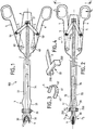
- la figure 1 est une vue de dessus schématique, avec arrachements partiels, d'une pince conforme à l'invention, avant une opération de suture d'un vaisseau sanguin ;
- la figure 2 est une vue analogue à la figure 1 montrant la pince à la fin de l'opération ;
- la figure 3 est une vue en perspective d'un clip ;
- la figure 4 montre en perspective l'extrémité du coulisseau qui porte les moyens de fermeture des mâchoires ;
- les figures 5 et 6 sont deux vues similaires qui représentent, en coupe longitudinale, l'extrémité de la pince, côté mâchoire, le coulisseau étant respectivement en position moyennement avancée et en position reculée ;
- la figure 7 est une vue en perspective, avec arrachement partiel, représentant la lame flexible qui porte la languette de retenue des clips, ainsi que la plaque fixe formant contre-rampe ;
- la figure 8 est une vue de dessus schématique au niveau de l'extrémité ouverte du magasin qui montre le transfert des clips dans les mâchoires ;
- les figures 9, 10 et 11 sont des vues de dessus schématiques du magasin et des mâchoires, ces vues illustrant trois étapes successives de mise en oeuvre de la pince en cours d'utilisation.
- Figure 1 is a schematic top view, partially broken away, of forceps according to the invention, before a suturing operation of a blood vessel;
- Figure 2 is a view similar to Figure 1 showing the clamp at the end of the operation;
- Figure 3 is a perspective view of a clip;
- Figure 4 shows in perspective the end of the slide which carries the jaw closure means;
- Figures 5 and 6 are two similar views which show, in longitudinal section, the end of the clamp, jaw side, the slide being respectively in the moderately advanced position and in the retracted position;
- Figure 7 is a perspective view, partially broken away, showing the flexible blade which carries the clip retaining tab, as well as the fixed plate forming counter-ramp;
- Figure 8 is a schematic top view at the open end of the magazine which shows the transfer of the clips in the jaws;
- Figures 9, 10 and 11 are schematic top views of the magazine and the jaws, these views illustrating three successive stages of implementation of the clamp in use.
La pince chirurgicale 100 représentée à la figure 1 - disposée à plat, horizontalement - possède un corps fixe 1 ayant une forme allongée ; seule son extrémité arrière (partie droite de la figure) a été représentée sur le dessin.The
Sur le corps 1 sont articulés, autour d'axes verticaux 40, une paire de leviers de manoeuvre 4 du genre branches de ciseaux, dont les extrémités libres sont conformées en anneaux permettant le passage des doigts. Sur chaque levier 4 est articulé, autour d'un axe vertical 50, une biellette 5. Les deux biellettes sont articulées, à leur extrémité opposée, autour d'un axe 51, sur l'extrémité d'un coulisseau 2. Celui-ci a la forme d'une tige, qui s'étend longitudinalement, coaxialement au corps fixe 1, et est guidé en translation dans celui-ci par des organes de guidage appropriés (glissières) non représentés.On the body 1 are articulated, around
A son autre extrémité (partie gauche de la figure) le coulisseau 2 a la forme d'un étrier 20 en forme de "U" renversé, comme cela est visible à la figure 4. On a désigné par les références 200 les branches latérales verticales de l'étrier 20.At its other end (left part of the figure) the
Dans le corps 1 est également montée une tige plate 3. Celle-ci est fixe, et présente une fente longitudinale 34 relativement longue, qui débouche à l'extrémité de la tige, du côté opposé aux leviers de manoeuvre 4 (à gauche sur la figure).In the body 1 is also mounted a
La fente 34 assure la séparation entre deux branches 33, dont les extrémités libres 30 ont la forme de mâchoires. La pièce 3 est réalisée dans un matériau, métallique ou plastique, ayant une bonne élasticité, de sorte qu'en appliquant sur les deux branches 33 un effort dirigé vers l'intérieur, on peut rapprocher l'une de l'autre les mâchoires 30. Sur les côtés des branches 33 sont prévues des pans inclinés 31 formant cames, aptes à coopérer avec les branches 200 de l'étrier 20, de telle sorte que le recul (déplacement vers la droite) de cet étrier provoque le rapprochement des deux mâchoires 30. Inversement, si l'étrier se déplace dans l'autre sens (avance) les branches 33 reviennent élastiquement à leur état initial représenté à la figure 1.The
Les mâchoires 30 sont conformées pour recevoir entre elles un clip 6 de type connu. Celui-ci a la forme générale d'un "U". Ainsi, dans l'exemple représenté à la figure 3, le clip 6 comprend deux branches latérales 60 qui sont reliées à une portion transversale 62 (fond du "U") par des parties obliques 61. Le clip est formé dans un fil métallique de section rectangulaire.The
Bien entendu, d'autres variantes de clips, ayant dans les détails une forme différente peuvent être utilisées, pourvu qu'ils aient une forme générale en "U".Of course, other variants of clips, having in detail a different shape can be used, provided that they have a general "U" shape.
A la figure 1, on a représenté un clip 6 en place entre les mâchoires 30. Au cours d'une intervention chirurgicale visant à ligaturer au moyen du clip un vaisseau sanguin VS, le chirurgien positionne la pince de telle manière que le clip 6 vienne entourer le vaisseau VS. Il agit ensuite sur les leviers 4 dans le sens de leur rapprochement (flèches F1, figure 2). Ce mouvement provoque, par l'intermédiaire des biellettes 5, un mouvement de translation longitudinale du coulisseau 2 dans le sens de son recul (flèche F2). L'étrier 20 provoque alors, en se déplaçant le long des cames 31, la fermeture des mâchoires 30 (flèches F3). Les mâchoires provoquent donc le sertissage du clip sur le vaisseau VS qui se trouve ainsi ligaturé.In Figure 1, there is shown a
Comme on le voit sur les figures 5 et 6, la partie fixe 1 possède une paroi inférieure plane 11 qui sert de fond de magasin pour la réserve de clips. On a désigné par la référence 10 la paroi supérieure de la partie fixe 1. Cette partie a la forme générale d'un fourreau recevant le coulisseau 2 et la pièce 3. Ce fourreau a une section générale rectangulaire, dont les parois sont échancrées à son extrémité avant afin de permettre le passage de l'étrier 20 et son accès aux branches 33 des mâchoires.As can be seen in FIGS. 5 and 6, the fixed part 1 has a
Les clips 6 sont stockés à plat les uns contre les autres sur le fond 11. Des guides latéraux 12 sous forme de nervures formés dans le corps 1 assurent la retenue des clips vers le haut. La réserve des clips est donc retenue et guidée dans un logement généralement tubulaire, appelé magasin linéaire 7, contenu dans le corps 1.The
Comme on le voit aux figures 9 à 11, le magasin 7 présente une extrémité ouverte 72 qui débouche du côté des mâchoires 30 et une extrémité fermée 73. Celle-ci sert d'appui à un (ou plusieurs) ressort(s) de poussée 71 qui agi(ssen)t sur un piston 70 qui s'applique contre le dernier clip de la rangée. Le ressort 71 tend donc à repousser toute la réserve de clips vers son extrémité ouverte 72.As seen in Figures 9 to 11, the
Sous le coulisseau 2 est fixé, par exemple par une soudure 85, une lame flexible 8. Celle-ci est recourbée vers le bas pour présenter une languette 81 à peu près perpendiculaire au plan général des clips, c'est-à-dire disposée verticalement si on considère que l'instrument se trouve placé horizontalement, ainsi que cela est illustré sur les dessins.Under the
La languette 81 a une largeur qui correspond approximativement à celle du tronçon transversal 62 des clips, de sorte qu'elle puisse venir se placer à l'intérieur d'un clip, contre cette partie transversale.The
Comme on le voit plus particulièrement à la figure 7, la lame 8 possède une partie plate 80 par laquelle elle est soudée au coulisseau 2, et se raccorde à la languette 81 par l'intermédiaire d'une partie 83 inclinée vers le bas. Cette partie présente un élargissement 84 dans laquelle sont découpées deux languettes latérales 82 rabattues vers l'avant (côté languette 81) et vers le haut. L'ensemble de la languette 8 s'inscrit à l'intérieur d'une ouverture 90 formée dans une plaque plane 9 solidaire du corps fixe 1.As seen more particularly in FIG. 7, the
L'ouverture 90 a une forme générale rectangulaire, présentant dans sa partie centrale un rétrécissement formé de deux languettes rectangulaires 900 tournées vers l'intérieur de l'ouverture, et dont les bords arrière sont référencés 93. Ces derniers sont adaptés pour servir de contre-rampes aux pattes inclinées 82 lorsque le coulisseau 2 avance.The
La zone avant 94 de la plaque 9 est légèrement inclinée vers le bas et son bord avant présente une échancrure en "V" 92, dont le rôle sera expliqué plus loin.The
Selon une caractéristique importante de l'invention, la lame flexible 8 est précontrainte de telle sorte que la languette 81 tend constamment à s'abaisser, à l'intérieur du magasin 7, dans la position illustrée à la figure 6.According to an important characteristic of the invention, the
En position reculée du coulisseau 2, la zone élargie 84 se trouve située en arrière des languettes fixes 900, et la languette se trouve donc normalement abaissée.In the retracted position of the
Lorsque le coulisseau avance, les pattes 82 rencontrent les bords arrière 93 de l'ouverture, et par effet de rampe, la lame 8 se déploie vers le haut, provoquant la remontée (et l'escamotage) de la languette 81.When the slide advances, the
En position avancée - illustrée à la figure 7 - la zone élargie 84 a franchi les languettes fixes 900, et la languette 81 est à nouveau abaissée.In the advanced position - illustrated in Figure 7 - the
Lors du recul du coulisseau, la zone 90 va passer cette fois sous les languettes fixes 900 et la languette 81 va donc rester en position basse.When the slide retracts, the
Les mâchoires 30 se trouvent juste à la sortie 72 du magasin 7. Le plan général des mâchoires à ce niveau est légèrement incliné vers l'avant et vers le bas d'un angle aigu u par rapport à l'horizontale (voir figure 6). Cet angle est de préférence égal à 15° environ.The
Sur les parois internes des mâchoires 30 sont prévues des butées frontales 330 servant d'arrêt à l'extrémité des branches du clip. Des butées basses 32 servent à sa retenue entre les mâchoires. D'autres butée peuvent être prévues, notamment pour éviter l'échappement du clip vers le haut, afin d'assurer son positionnement correct et sa bonne retenue entre les mâchoires, même si la pince est soumise à des mouvements intempestifs en directions variées (notamment si elle est retournée).On the internal walls of the
En position de repos, la pince se trouve dans la position de la figure 1, les leviers 4 étant écartés l'un de l'autre. Des moyens élastiques non représentés tels qu'un ressort, agissant soit sur les leviers 4 soit sur le coulisseau 2, maintiennent normalement les leviers 4 écartés et par conséquent le coulisseau 2 en position avancée. Dans cette position avancée du coulisseau, la zone élargie 84 se trouve au-delà (en avant) des languettes fixes 900, languette 81 abaissée.In the rest position, the clamp is in the position of Figure 1, the
Le ressort 71 repousse la rangée de clips vers la sortie du magasin, et le premier clip, désigné 6a, se trouve en butée à l'intérieur des mâchoires 30 ; le second clip 6b est en appui contre le clip 6a, avec un décalage angulaire dû à l'inclinaision (d'angle u) des mâchoires par rapport au magasin. La languette 81 se trouve entre les branches du clip 6b.The
Le clip 6a étant en place entre les mâchoires 30, la pince est utilisée de la manière suivante.The
Le chirurgien positionne la pince de telle manière que le vaisseau à ligaturer VS s'insère entre les mâchoires. Cette opération est facilitée grâce à l'échancrure en "V" 92 qui assure le bon centrage du vaisseau dans la zone centrale des mâchoires. Le chirurgien actionne ensuite les deux leviers 4 à la manière d'une paire de ciseaux pour les refermer, ce qui a pour effet de faire reculer le coulisseau 2. La languette 81 vient en contact avec la portion transversale du clip 6b et fait reculer celui-ci, ainsi que toute la rangée de clips 6, à l'encontre du ressort de poussée 71 qui se comprime. Ceci a pour effet d'isoler du reste des clips le clip 6a situé entre les mâchoires. Dans le même mouvement de recul du coulisseau 2, comme déjà expliqué, les mâchoires 30 se resserrent (flèches F3, figure 10) réalisant l'écrasement du clip et donc la suture du vaisseau.The surgeon positions the forceps so that the VS ligating vessel is inserted between the jaws. This operation is facilitated by the "V" cut 92 which ensures proper centering of the vessel in the central area of the jaws. The surgeon then actuates the two
Une fois que cette opération a été effectuée, le chirurgien libère les leviers 4 qui s'écartent l'un de l'autre (flèches F'1 à la figure 2) ceci provoque l'avance du coulisseau 2 (flèche F'2, figures 2 et 11). Les mâchoires 30 peuvent alors s'ouvrir (flèches F'3, figure 11).Once this operation has been carried out, the surgeon releases the
Les pattes 82 viennent dans le même temps en contact avec les bords 93 ce qui provoque la remontée et l'escamotage provisoire de la languette de retenue 81. Le clip 6b, toujours poussé par le ressort 71 vient alors se loger entre les mâchoires 30, remplaçant le clip 6a déjà posé. Le clip suivant 6c vient le remplacer à l'extrémité ouverte du magasin.The
L'avance du coulisseau se poursuivant, une fois que la zone élargie 84 a franchi les languettes fixes 900, la lame flexible 8 se déploie alors vers le bas, et la languette de retenue 81 vient se positionner en position d'interception du clip 6c.The advancement of the slide continuing, once the
L'opération qui vient d'être décrite est réitérée ensuite autant de fois que nécessaire au cours de l'intervention chirurgicale, le cas échéant jusqu'à épuisement complet de la réserve contenue dans le magasin 7.The operation which has just been described is then repeated as many times as necessary during the surgical intervention, if necessary until the reserve in the
Claims (10)
Priority Applications (2)
| Application Number | Priority Date | Filing Date | Title |
|---|---|---|---|
| FR9109931A FR2679763B1 (en) | 1991-07-31 | 1991-07-31 | SURGICAL PLIERS FOR POSITIONING SUTURE CLIPS. |
| EP93460004A EP0612505A1 (en) | 1991-07-31 | 1993-01-25 | Surgical forceps for applying suture clips |
Applications Claiming Priority (2)
| Application Number | Priority Date | Filing Date | Title |
|---|---|---|---|
| FR9109931A FR2679763B1 (en) | 1991-07-31 | 1991-07-31 | SURGICAL PLIERS FOR POSITIONING SUTURE CLIPS. |
| EP93460004A EP0612505A1 (en) | 1991-07-31 | 1993-01-25 | Surgical forceps for applying suture clips |
Publications (1)
| Publication Number | Publication Date |
|---|---|
| EP0612505A1 true EP0612505A1 (en) | 1994-08-31 |
Family
ID=26134781
Family Applications (1)
| Application Number | Title | Priority Date | Filing Date |
|---|---|---|---|
| EP93460004A Withdrawn EP0612505A1 (en) | 1991-07-31 | 1993-01-25 | Surgical forceps for applying suture clips |
Country Status (2)
| Country | Link |
|---|---|
| EP (1) | EP0612505A1 (en) |
| FR (1) | FR2679763B1 (en) |
Cited By (10)
| Publication number | Priority date | Publication date | Assignee | Title |
|---|---|---|---|---|
| EP0704190A1 (en) * | 1994-09-29 | 1996-04-03 | United States Surgical Corporation | Surgical clip applier |
| EP0769275A1 (en) * | 1995-10-20 | 1997-04-23 | United States Surgical Corporation | Surgical clip applier |
| US5772673A (en) * | 1996-03-07 | 1998-06-30 | United States Surgical Corporation | Apparatus for applying surgical clips |
| US5868759A (en) * | 1997-10-10 | 1999-02-09 | United States Surgical Corporation | Surgical clip applier |
| US6059799A (en) * | 1998-06-25 | 2000-05-09 | United States Surgical Corporation | Apparatus for applying surgical clips |
| EP1146823A1 (en) * | 1999-01-25 | 2001-10-24 | Applied Medical Resources Corporation | Modular ligating apparatus and method |
| US6599298B1 (en) | 2000-10-23 | 2003-07-29 | Vitalitec International, S.A. | Automatic surgical clip applier |
| DE102004033633A1 (en) * | 2004-07-12 | 2006-02-16 | Stryker Leibinger Gmbh & Co. Kg | Surgical instrument for handling a bent wire |
| US7731725B2 (en) | 1999-01-25 | 2010-06-08 | Applied Medical Resources Corporation | Surgical instrument with improved handle assembly |
| CN115194829A (en) * | 2022-07-14 | 2022-10-18 | 永康市第一人民医院 | Mengyule tail silk scissors under vaginal endoscope |
Families Citing this family (2)
| Publication number | Priority date | Publication date | Assignee | Title |
|---|---|---|---|---|
| US5607436A (en) * | 1993-10-08 | 1997-03-04 | United States Surgical Corporation | Apparatus for applying surgical clips |
| US5833696A (en) | 1996-10-03 | 1998-11-10 | United States Surgical Corporation | Apparatus for applying surgical clips |
Citations (3)
| Publication number | Priority date | Publication date | Assignee | Title |
|---|---|---|---|---|
| EP0086721A2 (en) * | 1982-02-17 | 1983-08-24 | United States Surgical Corporation | Apparatus for applying surgical clips |
| US4408603A (en) * | 1980-10-24 | 1983-10-11 | Blake Joseph W Iii | Surgical device |
| EP0286921A1 (en) * | 1987-04-06 | 1988-10-19 | Richard-Allan Medical Industries, Inc. | Hemostatic clip applicator for applying multiple clips |
-
1991
- 1991-07-31 FR FR9109931A patent/FR2679763B1/en not_active Expired - Fee Related
-
1993
- 1993-01-25 EP EP93460004A patent/EP0612505A1/en not_active Withdrawn
Patent Citations (3)
| Publication number | Priority date | Publication date | Assignee | Title |
|---|---|---|---|---|
| US4408603A (en) * | 1980-10-24 | 1983-10-11 | Blake Joseph W Iii | Surgical device |
| EP0086721A2 (en) * | 1982-02-17 | 1983-08-24 | United States Surgical Corporation | Apparatus for applying surgical clips |
| EP0286921A1 (en) * | 1987-04-06 | 1988-10-19 | Richard-Allan Medical Industries, Inc. | Hemostatic clip applicator for applying multiple clips |
Cited By (22)
| Publication number | Priority date | Publication date | Assignee | Title |
|---|---|---|---|---|
| AU689306B2 (en) * | 1994-09-29 | 1998-03-26 | United States Surgical Corporation | Surgical clip applicator |
| EP0704190A1 (en) * | 1994-09-29 | 1996-04-03 | United States Surgical Corporation | Surgical clip applier |
| US5643291A (en) * | 1994-09-29 | 1997-07-01 | United States Surgical Corporation | Surgical clip applicator |
| US5695502A (en) * | 1994-09-29 | 1997-12-09 | United States Surgical Corporation | Surgical clip applicator |
| EP1293166A3 (en) * | 1994-09-29 | 2003-11-26 | United States Surgical Corporation | Surgical clip applicator |
| EP1378203A1 (en) * | 1995-10-20 | 2004-01-07 | United States Surgical Corporation | Surgical clip applier |
| US5700270A (en) * | 1995-10-20 | 1997-12-23 | United States Surgical Corporation | Surgical clip applier |
| US5938667A (en) * | 1995-10-20 | 1999-08-17 | United States Surgical Corporation | Surgical clip applier |
| EP1609427A1 (en) * | 1995-10-20 | 2005-12-28 | United States Surgical Corporation | Surgical clip applier |
| EP1317906A1 (en) * | 1995-10-20 | 2003-06-11 | United States Surgical Corporation | Surgical clip applier |
| EP0769275A1 (en) * | 1995-10-20 | 1997-04-23 | United States Surgical Corporation | Surgical clip applier |
| US5772673A (en) * | 1996-03-07 | 1998-06-30 | United States Surgical Corporation | Apparatus for applying surgical clips |
| US5868759A (en) * | 1997-10-10 | 1999-02-09 | United States Surgical Corporation | Surgical clip applier |
| US6059799A (en) * | 1998-06-25 | 2000-05-09 | United States Surgical Corporation | Apparatus for applying surgical clips |
| EP1146823A1 (en) * | 1999-01-25 | 2001-10-24 | Applied Medical Resources Corporation | Modular ligating apparatus and method |
| EP1146823A4 (en) * | 1999-01-25 | 2003-03-05 | Applied Med Resources | Modular ligating apparatus and method |
| US7731725B2 (en) | 1999-01-25 | 2010-06-08 | Applied Medical Resources Corporation | Surgical instrument with improved handle assembly |
| US6599298B1 (en) | 2000-10-23 | 2003-07-29 | Vitalitec International, S.A. | Automatic surgical clip applier |
| DE102004033633A1 (en) * | 2004-07-12 | 2006-02-16 | Stryker Leibinger Gmbh & Co. Kg | Surgical instrument for handling a bent wire |
| DE102004033633B4 (en) * | 2004-07-12 | 2006-08-03 | Stryker Leibinger Gmbh & Co. Kg | Surgical instrument for handling a bent wire and surgical system |
| US7670357B2 (en) | 2004-07-12 | 2010-03-02 | Stryker Leibinger Gmbh & Co. Kg | Surgical instrument for manipulating a bent wire |
| CN115194829A (en) * | 2022-07-14 | 2022-10-18 | 永康市第一人民医院 | Mengyule tail silk scissors under vaginal endoscope |
Also Published As
| Publication number | Publication date |
|---|---|
| FR2679763B1 (en) | 1994-02-04 |
| FR2679763A1 (en) | 1993-02-05 |
Similar Documents
| Publication | Publication Date | Title |
|---|---|---|
| EP0645983A1 (en) | Blood vessel microanastomosis method and automatic gripper assembly therefor | |
| EP0612505A1 (en) | Surgical forceps for applying suture clips | |
| FR2480593A1 (en) | INSTRUMENT TO LIGATURE | |
| EP0077277A1 (en) | Method and device for applying haemostatic clips, and haemostatic clips for use with this device | |
| FR2554035A1 (en) | REVERSIBLE STAPLE FEEDING SHOE AND CLOSURE SYSTEM FOR THE STORE OF A STAPLE DRIVE TOOL | |
| FR2534802A1 (en) | INSTRUMENT OF SURGICAL LIGATION | |
| EP0748614A1 (en) | Force magnifying apparatus for a cutting forceps | |
| FR2498444A1 (en) | SURGICAL STAPLING INSTRUMENT TO BE DISPOSED OF AFTER USE | |
| FR2672554A1 (en) | PARKING HAND BRAKE FOR A MOTOR VEHICLE AND METHOD FOR MANUFACTURING THE LEVER OF THIS BRAKE. | |
| FR2525100A1 (en) | EXTRACTOR OF CHIRUGICAL STAPLES | |
| FR2499431A1 (en) | CRIMPING TOOL | |
| FR2480592A1 (en) | SURGICAL LIGATURE INSTRUMENT | |
| FR2695171A1 (en) | Pliers for clamping of collar onto extended organ which has limited access, for use in obstetrics - has two arms pivoted and spring loaded such that in rest position, jaws are pressed head to head against one another | |
| EP0229554B1 (en) | Apparatus for applying fastening elements to conveyor belts or the like | |
| FR2459632A1 (en) | ARTICULATION FOR CHAIR-LONG OR OTHER ARTICULATED SEAT | |
| FR2777061A1 (en) | PART FOR INSTALLING LONGILINE ELEMENTS AGAINST A WALL AND TOOL FOR FITTING THE SAID PART | |
| EP0139815A2 (en) | Safety ski binding | |
| EP0394106A1 (en) | Apparatus for applying fastening elements to conveyor belts or the like | |
| FR2642269A1 (en) | Device for installing and immobilising animals to be milked | |
| FR2650807A1 (en) | Device permitting the opening and closing of containers having a flattened shape when empty | |
| EP0391772A1 (en) | Apparatus for applying fastening elements to conveyor belts or the like | |
| EP0220967B1 (en) | Conveyor for containers | |
| FR2503771A1 (en) | Hand held stapler for installing roofing slate hooks - comprises magazine from which hooks are ejected to applicator press head | |
| FR2693045A1 (en) | Hand tool for placing connection terminal on end of insulated cable - has stripping and crimping mechanism operated by moving section, with connection pieces held in handle | |
| CH376223A (en) | Surgical instrument for suturing blood vessels, intestines, bronchi and other soft tissue |
Legal Events
| Date | Code | Title | Description |
|---|---|---|---|
| PUAI | Public reference made under article 153(3) epc to a published international application that has entered the european phase |
Free format text: ORIGINAL CODE: 0009012 |
|
| AK | Designated contracting states |
Kind code of ref document: A1 Designated state(s): DE GB IT |
|
| STAA | Information on the status of an ep patent application or granted ep patent |
Free format text: STATUS: THE APPLICATION IS DEEMED TO BE WITHDRAWN |
|
| 18D | Application deemed to be withdrawn |
Effective date: 19950301 |