EP0608835A2 - Method and apparatus for driving ink jet recording head - Google Patents
Method and apparatus for driving ink jet recording head Download PDFInfo
- Publication number
- EP0608835A2 EP0608835A2 EP94101060A EP94101060A EP0608835A2 EP 0608835 A2 EP0608835 A2 EP 0608835A2 EP 94101060 A EP94101060 A EP 94101060A EP 94101060 A EP94101060 A EP 94101060A EP 0608835 A2 EP0608835 A2 EP 0608835A2
- Authority
- EP
- European Patent Office
- Prior art keywords
- piezoelectric vibrating
- pressure producing
- vibrating element
- time
- producing chamber
- Prior art date
- Legal status (The legal status is an assumption and is not a legal conclusion. Google has not performed a legal analysis and makes no representation as to the accuracy of the status listed.)
- Granted
Links
Images


Classifications
-
- B—PERFORMING OPERATIONS; TRANSPORTING
- B41—PRINTING; LINING MACHINES; TYPEWRITERS; STAMPS
- B41J—TYPEWRITERS; SELECTIVE PRINTING MECHANISMS, i.e. MECHANISMS PRINTING OTHERWISE THAN FROM A FORME; CORRECTION OF TYPOGRAPHICAL ERRORS
- B41J2/00—Typewriters or selective printing mechanisms characterised by the printing or marking process for which they are designed
- B41J2/005—Typewriters or selective printing mechanisms characterised by the printing or marking process for which they are designed characterised by bringing liquid or particles selectively into contact with a printing material
- B41J2/01—Ink jet
- B41J2/015—Ink jet characterised by the jet generation process
- B41J2/04—Ink jet characterised by the jet generation process generating single droplets or particles on demand
- B41J2/045—Ink jet characterised by the jet generation process generating single droplets or particles on demand by pressure, e.g. electromechanical transducers
- B41J2/04501—Control methods or devices therefor, e.g. driver circuits, control circuits
- B41J2/04541—Specific driving circuit
-
- B—PERFORMING OPERATIONS; TRANSPORTING
- B41—PRINTING; LINING MACHINES; TYPEWRITERS; STAMPS
- B41J—TYPEWRITERS; SELECTIVE PRINTING MECHANISMS, i.e. MECHANISMS PRINTING OTHERWISE THAN FROM A FORME; CORRECTION OF TYPOGRAPHICAL ERRORS
- B41J2/00—Typewriters or selective printing mechanisms characterised by the printing or marking process for which they are designed
- B41J2/005—Typewriters or selective printing mechanisms characterised by the printing or marking process for which they are designed characterised by bringing liquid or particles selectively into contact with a printing material
- B41J2/01—Ink jet
- B41J2/015—Ink jet characterised by the jet generation process
- B41J2/04—Ink jet characterised by the jet generation process generating single droplets or particles on demand
- B41J2/045—Ink jet characterised by the jet generation process generating single droplets or particles on demand by pressure, e.g. electromechanical transducers
- B41J2/04501—Control methods or devices therefor, e.g. driver circuits, control circuits
- B41J2/04581—Control methods or devices therefor, e.g. driver circuits, control circuits controlling heads based on piezoelectric elements
-
- B—PERFORMING OPERATIONS; TRANSPORTING
- B41—PRINTING; LINING MACHINES; TYPEWRITERS; STAMPS
- B41J—TYPEWRITERS; SELECTIVE PRINTING MECHANISMS, i.e. MECHANISMS PRINTING OTHERWISE THAN FROM A FORME; CORRECTION OF TYPOGRAPHICAL ERRORS
- B41J2/00—Typewriters or selective printing mechanisms characterised by the printing or marking process for which they are designed
- B41J2/005—Typewriters or selective printing mechanisms characterised by the printing or marking process for which they are designed characterised by bringing liquid or particles selectively into contact with a printing material
- B41J2/01—Ink jet
- B41J2/015—Ink jet characterised by the jet generation process
- B41J2/04—Ink jet characterised by the jet generation process generating single droplets or particles on demand
- B41J2/045—Ink jet characterised by the jet generation process generating single droplets or particles on demand by pressure, e.g. electromechanical transducers
- B41J2/04501—Control methods or devices therefor, e.g. driver circuits, control circuits
- B41J2/04588—Control methods or devices therefor, e.g. driver circuits, control circuits using a specific waveform
-
- B—PERFORMING OPERATIONS; TRANSPORTING
- B41—PRINTING; LINING MACHINES; TYPEWRITERS; STAMPS
- B41J—TYPEWRITERS; SELECTIVE PRINTING MECHANISMS, i.e. MECHANISMS PRINTING OTHERWISE THAN FROM A FORME; CORRECTION OF TYPOGRAPHICAL ERRORS
- B41J2/00—Typewriters or selective printing mechanisms characterised by the printing or marking process for which they are designed
- B41J2/005—Typewriters or selective printing mechanisms characterised by the printing or marking process for which they are designed characterised by bringing liquid or particles selectively into contact with a printing material
- B41J2/01—Ink jet
- B41J2/015—Ink jet characterised by the jet generation process
- B41J2/04—Ink jet characterised by the jet generation process generating single droplets or particles on demand
- B41J2/045—Ink jet characterised by the jet generation process generating single droplets or particles on demand by pressure, e.g. electromechanical transducers
- B41J2/04501—Control methods or devices therefor, e.g. driver circuits, control circuits
- B41J2/04593—Dot-size modulation by changing the size of the drop
-
- B—PERFORMING OPERATIONS; TRANSPORTING
- B41—PRINTING; LINING MACHINES; TYPEWRITERS; STAMPS
- B41J—TYPEWRITERS; SELECTIVE PRINTING MECHANISMS, i.e. MECHANISMS PRINTING OTHERWISE THAN FROM A FORME; CORRECTION OF TYPOGRAPHICAL ERRORS
- B41J2/00—Typewriters or selective printing mechanisms characterised by the printing or marking process for which they are designed
- B41J2/005—Typewriters or selective printing mechanisms characterised by the printing or marking process for which they are designed characterised by bringing liquid or particles selectively into contact with a printing material
- B41J2/01—Ink jet
- B41J2/135—Nozzles
- B41J2/14—Structure thereof only for on-demand ink jet heads
- B41J2/14201—Structure of print heads with piezoelectric elements
- B41J2/14274—Structure of print heads with piezoelectric elements of stacked structure type, deformed by compression/extension and disposed on a diaphragm
Definitions
- the present invention relates to a recording apparatus for printing print data including image data by jetting an ink droplet from a nozzle opening while displacing a pressure producing chamber using a piezoelectric vibrating element.
- thermal printers capable can print such data at a high dot density and tone
- these printers entail high operating costs due to expensive ink ribbons the like.
- ink jet printers whose operating costs are lower, are often used.
- a technique for changing the size of the ejected ink droplets is described in Japanese Patent Unexamined Publication No. Hei. 2-6137. That is, the size of an ink droplet is changed by adjusting the maximum or minimum voltage applied to a pressure producing element.
- this drive method ink droplets of different sizes are ejected by changing the volume of the contracted pressure producing chamber at the time of ejecting the ink droplets, and the volume is returned to the initial condition thereafter.
- the meniscus and the vibration of the pressure producing element after the ink droplet has been ejected differ from one ejection operation to another, thereby impairing the print quality due to the ejection of tiny ink droplets after the main ink droplet has been ejected.
- the invention provides a method for driving an ink jet recording head according to independent claim 1 and an apparatus according to independent claim 2. Further advantageous features, aspects and details of the invention are evident from the dependent claims, the description and the drawings. The claims are intended to be understood as a first non-limiting approach of defining the invention in general terms.
- the invention provides a method for driving an ink jet recording head having a pressure producing chamber communicating with a nozzle opening and a piezoelectric vibrating element for expanding and contracting the pressure producing chamber, the method comprising the steps of: expanding the pressure producing chamber in an initial condition to a predetermined volume over a first time period which is longer than a natural vibration cycle of the piezoelectric vibrating element and which corresponds to a size of an ink droplet to be ejected; maintaining the pressure producing chamber as expanded for a second predetermined period of time with an expansion start time as a reference; and then contracting the pressure producing chamber to the initial condition over a third predetermined time which is longer than the natural vibration cycle of the piezoelectric vibrating element, so that the ink droplet can be ejected.
- the pressure producing chamber When the pressure producing chamber is expanded to the predetermined volume over the first predetermined time, which is longer than the natural vibration cycle of the piezoelectric vibrating element, to supply ink, the meniscus adjacent to the nozzle opening is strongly pulled toward the pressure producing chamber, and then quickly returns to the nozzle opening, inducing vibration while rising up from the nozzle opening. While the cycle of this vibration takes a certain value defined by an ink flow path system, the rising amount depends on the amplitude of the vibration in accordance with the pressure producing chamber expansion speed.
- the size of the ejecting ink droplet is changed because the rising amount of the meniscus depends on the pressure producing chamber expansion speed.
- the ink droplet ejection speed is maintained constant irrespective of the volume of the ink droplet because such speed depends on the volume velocity at the time of contracting the pressure producing chamber, thereby preventing the ink droplet from being positioned out of place on the recording paper.
- Figure 1 is an exploded diagram showing an assembly of an exemplary ink jet recording head used in the invention.
- reference numeral 1 designates a nozzle plate having arrays 3 of nozzle openings with the nozzles being formed at a predetermined pitch, e.g ., 180 dpi. Each array has nozzle openings 2 ( Figure 2).
- Reference numeral 4 designates a spacer interposed between a vibrating plate 10 (described later) and the nozzle plate 1.
- the spacer 4 defines pressure producing chambers 5 and reservoirs 6 so as to correspond respectively to the arrays of nozzle openings as shown in Figure 2.
- Ink supply ports 7 communicating with the pressure producing chambers 5 and the reservoirs 6 are also formed in the spacer 4.
- Reference numeral 10 designates the vibrating plate, which forms the pressure producing chambers 5 while confronting the nozzle plate 1 through the spacer 4.
- the vibrating plate 10 includes island portions 15 and thin portions 10a around the island portions 15.
- Each island portion 15 has a rigidity such that displacements induced by contraction and expansion can be transmitted to as wide an area as possible by causing the vibrating plate 10 to abut against a distal end of a piezoelectric vibrating element 14 of a piezoelectric vibrating element unit 12 (described later) as shown in Figure 2.
- the pressure producing chamber 5 can be contracted and expanded efficiently in response to the contraction and expansion of the corresponding piezoelectric vibrating element 14.
- each piezoelectric vibrating element unit 12 includes half of the piezoelectric vibrating elements 14.
- the piezoelectric vibrating element unit 12 is fixed on a fixed plate 16 with the piezoelectric vibrating elements 14 being arranged at a predetermined pitch.
- the piezoelectric vibrating elements 14 vibrate in a vertical vibrating mode.
- Each vibrating element 14 is, as shown in Figure 4, arranged so that a plurality of sets, each set composed of a piezoelectric vibrating material 22 interposed between a drive electrode 23 and a common electrode 24, are laminated one upon another in sandwich-like form.
- the drive electrodes 23 are exposed from a lateral side of the piezoelectric vibrating element 14 and connected in parallel to one another through a drive external electrode 25 formed by, e.g ., vapor deposition.
- the common electrodes 24 are exposed from the other lateral side of the piezoelectric vibrating element 14 and connected in parallel to one another through a common external electrode 26.
- the common external electrode 26 is connected through an electrically conductive member 27.
- reference numeral 32 designates a substrate, which has unit accommodating holes 33 and an ink supply port 34 for supplying ink from an ink tank to the ink reservoirs 6.
- the unit accommodating holes 33 accommodate the vibrating element units 12 so that free ends of the piezoelectric vibrating elements 14 are exposed therefrom.
- the vibrating plate 10, the spacer 4, and the nozzle plate 1 are aligned on a surface of the substrate 32 and fixed by a frame body 35 to form a recording head body.
- the frame body 35 serves also as an electrostatic shield.
- Reference numeral 36 in Figure 1 designates a base plate for mounting the recording head on a carriage.
- the vibrating plate 10 is made of a metal plate or a synthetic resin plate so that the vibrating plate 10 can be deformed at a higher efficiency by the displacement of the piezoelectric vibrating element 14.
- the piezoelectric vibrating element 14 is expanded ( Figure 2(b) to jet an ink droplet under a condition in which the piezoelectric vibrating element 14 is subsequently contracted ( Figure 2(a))
- the corresponding pressure producing chamber 5 is compressed in response to the expansion of the piezoelectric vibrating element 14.
- the ink pressure in the pressure producing chamber 5 is increased on the order of several atmospheres of pressure substantially instantly to eject the ink present in the pressure producing chamber 5 as an ink droplet.
- Reference numeral 15 in Figure 2 designates the island portion for transmitting the displacement of the piezoelectric vibrating element 14 over a wide area on the vibrating plate 10.
- the piezoelectric vibrating element When the residual vibration of the piezoelectric vibrating element is transmitted to the ink in the pressure producing chamber through the vibrating plate 10, the meniscus of the corresponding nozzle opening 2 starts vibrating in an extremely unstable manner due to the very short cycle of the residual vibration, and when the meniscus reaches a predetermined position, it becomes extremely difficult for the piezoelectric vibrating element to vibrate with satisfactory repetitiveness. If, while the meniscus is vibrating, the piezoelectric vibrating element is caused to expand to produce ink droplets, ink droplets are ejected without fail, but dots to be formed on the recording paper by such ink droplets are subjected to variations due to variations in the size and ejection speed of the ink droplets in dependence on the position of the meniscus.
- the charging cycle T1 as well as the discharging cycle T2 of the piezoelectric vibrating element 14 are set to intervals longer than the natural vibration cycle Ta thereof. If the piezoelectric vibrating element 14 is charged or discharged under these conditions ( Figure 5(c)), the piezoelectric vibrating element 14 is displaced and expands as directed by a drive waveform without causing residual vibration, as shown in Figure 5(d). In this case, the meniscus produces regular vibrations of a cycle longer than the natural vibration cycle of the piezoelectric vibrating element 14.
- the charging and the discharging cycles are set to intervals longer than the natural vibration cycle Ta, i.e., the rise time T1 and the fall time T2 are set to intervals longer than the natural vibration cycle Ta of the piezoelectric vibrating element 14, and it is also possible to set the piezoelectric vibrating element 14 drive timing for jetting an ink droplet by taking into account the displacement derived from the vibration of the meniscus. As a result, stable ink droplets can be produced while the meniscus is vibrating.
- Figure 6 shows an exemplary circuit for driving the ink jet recording head.
- reference numeral IN1 designates an input terminal which receives a print auxiliary signal S1 for generating a drive voltage that causes the pressure producing chamber 5 of the recording head to contract (which is the standby state) or causes the pressure producing chamber 5 to expand (which is the state in which ink is sucked into the chamber 5), and
- INd designates a data input terminal for receiving data from a host apparatus.
- Reference numeral 40 designates a text/graphics data judging unit, which judges whether data inputted to a print buffer 41 from the terminal INd is text data or graphics image data based on the inputted data, and outputs a reference voltage Vref to a variable time constant adjusting unit 43 (described later) in accordance with the result of the judgment.
- Reference numeral 43 designates the variable time constant adjusting unit, which adjusts the pressure producing chamber 5 expansion speed. The variable time constant adjusting unit 43 adjusts arbitrarily the time constant by the reference voltage Vref from the data judging means 40.
- a reference voltage Vref1 is inputted, which sets a first time constant that is longer than the natural vibration cycle of the piezoelectric vibrating element 14, whereas in the case where the print data includes only graphics image data, a reference voltage Vref2 is inputted, which sets a second time constant that is longer than the first time constant.
- Reference numeral 42 designates a fixed time constant adjusting unit for setting a pressure producing chamber 5 contracting speed, which is set so as to yield a contraction interval longer than the natural vibration cycle of the piezoelectric vibrating element 14.
- Reference numeral 44 designates a switching transistor whose base is connected to the input terminal IN1.
- the switching transistor 44 controls the operation of the fixed time constant adjusting unit 42 with the print auxiliary signal S1 inputted to the terminal IN1 in synchronism with a print timing signal.
- the fixed time constant adjusting unit 42 is activated when the transistor 44 is turned on, and generates a voltage waveform for causing the piezoelectric vibrating element 14 to expand at a time constant determined by a circuit constant to thereby bring the pressure producing chamber 5 into the contracting state, which is the standby state.
- Reference numeral 48 designates a switching transistor whose base is connected to the terminal IN1. This switching transistor 48 operates the variable time constant adjusting unit 43 by turning a transistor 49 off when the fixed time constant adjusting unit 42 is inoperative. The variable time constant adjusting unit 43 generates a voltage waveform for causing the piezoelectric vibrating element 14 to contract at a time constant determined by a circuit constant to thereby expand the pressure producing chamber 5.
- reference numerals 50 and 51 designate current amplifying transistors.
- the respective piezoelectric vibrating elements 14 have first terminals thereof connected to the current amplifying transistors 50 and 51, and the second terminals thereof grounded through transistors T that are to be turned on by print signals.
- a diode D is inserted to connect the collector and the emitter of each transistor.
- the fixed time constant adjusting means 42 Since the voltage level of the print auxiliary signal S1 to be inputted to the terminal IN1 is initially high, the fixed time constant adjusting means 42 is operative, and therefore the commonly connecting terminal side of the piezoelectric vibrating element 14 is maintained at a negative potential of substantially -VL (volts). As a result, all the piezoelectric vibrating elements 14 are charged through the diodes D so that these elements are caused to expand, thus keeping the pressure producing chambers 5 contracted.
- the print data judging unit 40 Upon input of print data from the host apparatus to the print buffer 41, the print data judging unit 40 checks if the print data includes graphics image data. Since the print data includes only text data in this case, the print data judging unit 40 outputs the reference Voltage Vref1 for text data.
- a print timing signal for forming a single dot is generated at a time t1 by a printer body (not shown), and in synchronism therewith, the print auxiliary signal S1 that has been high goes low and is received by the terminal IN1.
- the transistor 44 is turned off to inhibit the operation of the fixed time constant adjusting unit 42.
- the transistor 48 and also the transistor 49 are turned off to operate the variable time constant adjusting unit 43.
- the terminal voltage of a capacitor 47 is increased to 0 (volt) from substantially -VL (volts) by the reference voltage Vref1 at a rate determined by the first time constant defined by the circuit constant, thus to generate the drive voltage from the current amplifying transistors 50 and 51.
- the piezoelectric vibrating element 14 stops without undergoing a damped oscillator motion, thereby stopping the volumetric change of the pressure producing chamber 5.
- the meniscus formed adjacent to the nozzle opening 2 vibrates at a vibration cycle defined by a flow path system irrespective of the displacement of the piezoelectric vibrating element 14, thus changing the position thereof with time ( Figure 7(d)).
- the above operation is repeated so that a dot is formed on the recording paper every time a print timing signal is generated as the recording head moves.
- the print data judging unit 40 outputs to the variable time constant adjusting unit 43 the reference voltage signal Vref2 for setting the second time constant that is longer than the first time constant.
- the print timing signal for forming a single dot is similarly generated at time t1 from the printer body (not shown), and in synchronism therewith, the print auxiliary signal S1 that has been high goes low and is inputted to the terminal IN1.
- the transistor 44 turns off to inhibit the operation of the fixed time constant adjusting unit 42, and simultaneously therewith, the transistor 48 and the transistor 49 turn off to operate the variable time constant adjusting unit 43.
- This operation of the variable time constant adjusting unit 43 increases the terminal voltage of the capacitor 47 to 0 (volt) from substantially -VL (volts) at the second time constant that is longer than the first time constant defined by the circuit constant, so that a drive voltage is generated by the current amplifying transistors 50 and 51.
- the piezoelectric vibrating elements 14 connected to the transistors T that have been turned on by the print signals at an interval between times t1 and t2 are discharged through the transistors T ( Figure 7(b)). Accordingly, the piezoelectric vibrating elements 14 contract, whereas the pressure producing chambers 5 expand ( Figure 7(c)). The expansion of the pressure producing chambers 5 introduces ink to the pressure producing chambers 5 through the ink supply ports 7 from the reservoirs 6, and at the same time, the meniscuses of the nozzle openings 2 retreat toward the pressure producing chambers 5 ( Figure 7(d)).
- the diode 52 blocks the increase in the terminal voltage, so that the drive voltage is thereafter maintained at a fixed level of substantially 0 (volt) until the print auxiliary signal S1 goes high from low.
- the second time constant i.e ., the interval between times t1 and t2
- the piezoelectric vibrating element 14 stops without undergoing oscillatory damping, whereas the volumetric change of the pressure producing chamber 5 is also stopped.
- the meniscus formed adjacent to the nozzle opening 2 vibrates at a vibrating cycle defined by the flow path system irrespective of the displacement of the piezoelectric vibrating element 14, thus changing the position thereof with time ( Figure 7(d)).
- the piezoelectric vibrating elements 14 that are discharged by the print signals in the above operation expand while charged through the diodes D with the common connecting terminal side as the negative potential ( Figure 7(b)). Accordingly, the pressure producing chambers 5 contract, which causes ink droplets to be jetted from the corresponding nozzle openings 2 to from dots on the recording paper.
- the above operation is repeated so that a dot is formed on the recording paper every time a print timing signal is generated as the recording head moves.
- the piezoelectric vibrating element 14 expands at a fixed speed
- the pressure producing chamber 5 contracting speed is also fixed. Therefore, no change takes place in the ink droplet ejection speed irrespective of the volume of the ink droplet. This means that the ink droplet is onto a single point on the recording paper irrespective of the volume thereof, thus achieving printing with an amount of ink corresponding to the print data without impairing the print quality.
- Figure 8 shows the relationship between the pressure producing chamber 5 expansion speed and the volume of an ink droplet (a curve indicated by a broken line), and the relationship between the pressure producing chamber 5 expansion speed and the ink droplet ejection speed (a curve indicated by a solid line). This figure shows that when the pressure producing chamber 5 is caused to expand at a cycle longer than the natural vibration cycle of the piezoelectric vibrating element 14, the ink droplet ejection speed remains at a fixed level irrespective of the volume thereof, even though the volume thereof increases with increasing pressure producing chamber 5 expansion speed.
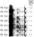
- Figure 9 is a series of photographs indicating the size of an ink droplet as well as the distance thereof from the nozzle opening, i.e. , the ink droplet ejection speed. More specifically, the photographs show conditions adjacent to the nozzle opening after the elapse of a predetermined time from the generation of the ink droplet, which is produced by not only changing the piezoelectric vibrating element 14 contracting speed, i.e. , the pressure producing chamber 5 expanding time to a level of 20 ⁇ sec at intervals of 2 ⁇ sec from 8 ⁇ sec, but also the expansion of the piezoelectric vibrating element 14 after the elapse of a predetermined time from the time of starting of the contraction of the piezoelectric vibrating element 14.
- the tips of the respective ink droplets are positioned flush with one another. That is, it is demonstrated that the volume of the ink droplet can be adjusted by changing the pressure producing chamber 5 expansion speed without changing the ink droplet ejection speed.
- reference numeral 72 designates a variable time constant adjusting unit for setting the pressure producing chamber expansion speed. If the signal from the data judging unit 40 indicates that the print data includes only text data, the first time constant that is longer than the natural vibration cycle of the piezoelectric vibrating element 64 is set, whereas if the print data includes only graphics image data, the second time constant that is longer than the first time constant is set.
- Reference numeral 73 designates a fixed time constant adjusting unit for setting the pressure producing chamber contracting speed. The fixed time constant is a time longer than the natural vibration cycle of the piezoelectric vibrating element 64 in this embodiment.
- the piezoelectric vibrating elements 64 have first terminals thereof connected to the current amplifying transistors 50 and 51, and the second terminals thereof grounded through the transistors T.
- a diode D is inserted to connect the emitter and the collector of each transistor T. Since the voltage level of the print auxiliary signal S1 to be inputted to the terminal IN1 is initially high, the fixed time constant adjusting unit 73 is operative, and therefore the common connecting terminal side of the piezoelectric vibrating element 64 is maintained at a fixed level of substantially 0 (volt). As a result, all the piezoelectric vibrating elements 64 are discharged through the diodes D to substantially zero the applied voltage.
- the pressure producing chamber 5 is caused to expand during the time the piezoelectric vibrating element 64 is being charged, whereas the voltage applied to the piezoelectric vibrating element 64 becomes substantially zero during the time the piezoelectric vibrating element 64 is being discharged, so that an ink droplet is jetted when the pressure producing chamber 5 being contracted. Therefore, by setting the time constant of the variable time constant adjusting unit 72 to a long interval in response to the signal from the data judging unit 40 in the case of printing image data and to a short interval in the case of printing text data, the volume of the ink droplet can be adjusted with the ink droplet ejection speed maintained at a fixed level in a manner similar to that of the above-mentioned embodiment.
- the pressure producing chamber expansion speed is set to two levels in the above embodiments. If such speed is adjusted to three or more levels in accordance with the density of an image, a more subtle density adjustment can be given to the image data. That is, if an image has a high dot density, the size of an ink droplet can be adjusted to be smaller, whereas if an image has a low dot density, a dot containing a larger amount of ink is used for the printing. As a result, a uniform density can be maintained over the entire part of the image.
- the invention is characterized as adjusting the volume of an ink droplet without changing the ink droplet ejection speed.
- This operation can be performed by ejection an ink droplet with the pressure producing chamber in an initial condition expanded to a predetermined volume over a time which is longer than the natural vibration cycle of the piezoelectric vibrating element and which corresponds to the size of the ink droplet to be ejected, by maintaining the pressure producing chamber as expanded for a predetermined interval with the expansion start time as a reference, and then by contracting the pressure producing chamber to the initial condition over a predetermined time that is longer than the natural vibration cycle of the piezoelectric vibrating element in a method for driving an ink jet recording head having not only pressure producing chambers communicating with nozzle openings but also piezoelectric vibrating elements for expanding and contracting the pressure producing chambers.
Abstract
Description
- The present invention relates to a recording apparatus for printing print data including image data by jetting an ink droplet from a nozzle opening while displacing a pressure producing chamber using a piezoelectric vibrating element.
- As personal computers are gaining in popularity and graphics data processing technology is improving, production of high quality hard copies not only in terms of character data but also in graphics images has been called for.
- While thermal printers capable can print such data at a high dot density and tone, these printers entail high operating costs due to expensive ink ribbons the like. To overcome this problem, ink jet printers, whose operating costs are lower, are often used.
- However, in the case of printing, for example, a so-called solid image that covers all or a large portion of the surface of the recording paper, a process involving wetting the entire surface of the recording paper with ink must be employed. As a result, the hard copy tends to wrinkle and that it takes a long time to dry the hard copy. Further, in the case of printing a color image, the size of the ink droplets ejected from the recording head must be changed to express density gradations.
- A technique for changing the size of the ejected ink droplets is described in Japanese Patent Unexamined Publication No. Hei. 2-6137. That is, the size of an ink droplet is changed by adjusting the maximum or minimum voltage applied to a pressure producing element. According to this drive method, ink droplets of different sizes are ejected by changing the volume of the contracted pressure producing chamber at the time of ejecting the ink droplets, and the volume is returned to the initial condition thereafter. As a result, the meniscus and the vibration of the pressure producing element after the ink droplet has been ejected differ from one ejection operation to another, thereby impairing the print quality due to the ejection of tiny ink droplets after the main ink droplet has been ejected.
- It is therefore an object of the present invention to provide a method and apparatus for driving an ink jet recording head, in which the size of an ink droplet can be changed by maintaining the ink droplet ejection speed constant with the volume of a contracted pressure producing chamber maintained constant.
- For this purpose, the invention provides a method for driving an ink jet recording head according to
independent claim 1 and an apparatus according toindependent claim 2. Further advantageous features, aspects and details of the invention are evident from the dependent claims, the description and the drawings. The claims are intended to be understood as a first non-limiting approach of defining the invention in general terms. - The invention provides a method for driving an ink jet recording head having a pressure producing chamber communicating with a nozzle opening and a piezoelectric vibrating element for expanding and contracting the pressure producing chamber, the method comprising the steps of: expanding the pressure producing chamber in an initial condition to a predetermined volume over a first time period which is longer than a natural vibration cycle of the piezoelectric vibrating element and which corresponds to a size of an ink droplet to be ejected; maintaining the pressure producing chamber as expanded for a second predetermined period of time with an expansion start time as a reference; and then contracting the pressure producing chamber to the initial condition over a third predetermined time which is longer than the natural vibration cycle of the piezoelectric vibrating element, so that the ink droplet can be ejected.
- When the pressure producing chamber is expanded to the predetermined volume over the first predetermined time, which is longer than the natural vibration cycle of the piezoelectric vibrating element, to supply ink, the meniscus adjacent to the nozzle opening is strongly pulled toward the pressure producing chamber, and then quickly returns to the nozzle opening, inducing vibration while rising up from the nozzle opening. While the cycle of this vibration takes a certain value defined by an ink flow path system, the rising amount depends on the amplitude of the vibration in accordance with the pressure producing chamber expansion speed.
- When the pressure producing chamber is caused to contract over the third predetermined time, which is longer than the natural vibration cycle of the piezoelectric vibrating element, at the time the meniscus has returned to the nozzle opening, the size of the ejecting ink droplet is changed because the rising amount of the meniscus depends on the pressure producing chamber expansion speed. On the other hand, the ink droplet ejection speed is maintained constant irrespective of the volume of the ink droplet because such speed depends on the volume velocity at the time of contracting the pressure producing chamber, thereby preventing the ink droplet from being positioned out of place on the recording paper.
- In the drawings
- Figure 1 is an exploded diagram showing an assembly of an exemplary ink jet recording head used in the invention;
- Figures 2(a) and 2(b) are diagrams showing a state in which a piezoelectric vibrating element is contracted and a state in which the piezoelectric vibrating element is expanded in the recording head shown in Figure 1;
- Figure 3 is a diagram showing an exemplary piezoelectric vibrating element unit used in the recording head shown in Figure 1;
- Figure 4 is a diagram showing an exemplary piezoelectric vibrating element constituting the piezoelectric vibrating element unit;
- Figures 5(a) and 5(b) are diagrams showing a drive voltage signal shorter than the natural vibration cycle of a piezoelectric vibrating element and a displacement of the piezoelectric vibrating element brought about thereby, and Figures 5(c) and 5(d) are diagrams showing a drive voltage signal longer than the natural vibration cycle of the piezoelectric vibrating element and a displacement of the piezoelectric vibrating element brought about thereby;
- Figure 6 is a block diagram showing an exemplary drive circuit for driving the recording head shown in Figure 1;
- Figures 7(a), 7(b), 7(c) and 7(d) are diagrams showing operations of the drive circuit of the invention, in which Figure 7(a) shows a print auxiliary signal; Figure 7(b), the operation of charging and discharging a piezoelectric vibrating element; Figure 7(c), a change in the volume of a pressure producing chamber; and Figure 7(d) the position of a meniscus;
- Figure 8 is a diagram showing a relationship between the size of an ink droplet and the ink droplet ejection speed defined by the drive circuit;
- Figures 9(a) to 9(g) are photographs showing an ink droplet, the photographs being taken while a pressure producing chamber expanding time is being changed every predetermined interval from an expansion start time;
- Figure 10 is a sectional view showing another exemplary piezoelectric vibrating element to which the invention can be applied; and
- Figure 11 is a block diagram showing an exemplary drive circuit of the invention which is suitable for driving a recording head using the piezoelectric vibrating element shown in Figure 10.
- Details of the invention will now be described with reference to preferred embodiments shown in the drawings.
- Figure 1 is an exploded diagram showing an assembly of an exemplary ink jet recording head used in the invention. In Figure 1,
reference numeral 1 designates a nozzleplate having arrays 3 of nozzle openings with the nozzles being formed at a predetermined pitch, e.g., 180 dpi. Each array has nozzle openings 2 (Figure 2). -
Reference numeral 4 designates a spacer interposed between a vibrating plate 10 (described later) and thenozzle plate 1. Thespacer 4 definespressure producing chambers 5 andreservoirs 6 so as to correspond respectively to the arrays of nozzle openings as shown in Figure 2.Ink supply ports 7 communicating with thepressure producing chambers 5 and thereservoirs 6 are also formed in thespacer 4. -
Reference numeral 10 designates the vibrating plate, which forms thepressure producing chambers 5 while confronting thenozzle plate 1 through thespacer 4. The vibratingplate 10 includesisland portions 15 andthin portions 10a around theisland portions 15. Eachisland portion 15 has a rigidity such that displacements induced by contraction and expansion can be transmitted to as wide an area as possible by causing the vibratingplate 10 to abut against a distal end of a piezoelectric vibratingelement 14 of a piezoelectric vibrating element unit 12 (described later) as shown in Figure 2. As a result of this construction, thepressure producing chamber 5 can be contracted and expanded efficiently in response to the contraction and expansion of the corresponding piezoelectric vibratingelement 14. - As shown in Figure 3, each piezoelectric
vibrating element unit 12 includes half of thepiezoelectric vibrating elements 14. The piezoelectricvibrating element unit 12 is fixed on afixed plate 16 with the piezoelectric vibratingelements 14 being arranged at a predetermined pitch. The piezoelectricvibrating elements 14 vibrate in a vertical vibrating mode. - Each vibrating
element 14 is, as shown in Figure 4, arranged so that a plurality of sets, each set composed of a piezoelectric vibratingmaterial 22 interposed between adrive electrode 23 and acommon electrode 24, are laminated one upon another in sandwich-like form. Thedrive electrodes 23 are exposed from a lateral side of the piezoelectric vibratingelement 14 and connected in parallel to one another through a driveexternal electrode 25 formed by, e.g., vapor deposition. Thecommon electrodes 24 are exposed from the other lateral side of the piezoelectric vibratingelement 14 and connected in parallel to one another through a commonexternal electrode 26. The commonexternal electrode 26 is connected through an electricallyconductive member 27. - Returning to Figure 1,
reference numeral 32 designates a substrate, which hasunit accommodating holes 33 and anink supply port 34 for supplying ink from an ink tank to theink reservoirs 6. Theunit accommodating holes 33 accommodate the vibratingelement units 12 so that free ends of the piezoelectric vibratingelements 14 are exposed therefrom. The vibratingplate 10, thespacer 4, and thenozzle plate 1 are aligned on a surface of thesubstrate 32 and fixed by aframe body 35 to form a recording head body. Theframe body 35 serves also as an electrostatic shield.Reference numeral 36 in Figure 1 designates a base plate for mounting the recording head on a carriage. - In this construction, the
vibrating plate 10 is made of a metal plate or a synthetic resin plate so that the vibratingplate 10 can be deformed at a higher efficiency by the displacement of the piezoelectric vibratingelement 14. When thepiezoelectric vibrating element 14 is expanded (Figure 2(b) to jet an ink droplet under a condition in which the piezoelectricvibrating element 14 is subsequently contracted (Figure 2(a)), then the correspondingpressure producing chamber 5 is compressed in response to the expansion of the piezoelectric vibratingelement 14. As a result, the ink pressure in thepressure producing chamber 5 is increased on the order of several atmospheres of pressure substantially instantly to eject the ink present in thepressure producing chamber 5 as an ink droplet.Reference numeral 15 in Figure 2 designates the island portion for transmitting the displacement of the piezoelectric vibratingelement 14 over a wide area on the vibratingplate 10. - It is known that when a piezoelectric vibrating
element 14 that vibrates vertically is charged at a cycle T1 that is shorter than a natural vibration cycle Ta thereof or discharged at a cycle T2 that is also shorter than the natural vibration cycle Ta (Figure 5(a)), the piezoelectric vibrating element itself generates a residual vibration at the natural vibration cycle Ta after the charging or discharging has been completed, as shown in Figure 5(b). When the residual vibration of the piezoelectric vibrating element is transmitted to the ink in the pressure producing chamber through thevibrating plate 10, the meniscus of thecorresponding nozzle opening 2 starts vibrating in an extremely unstable manner due to the very short cycle of the residual vibration, and when the meniscus reaches a predetermined position, it becomes extremely difficult for the piezoelectric vibrating element to vibrate with satisfactory repetitiveness. If, while the meniscus is vibrating, the piezoelectric vibrating element is caused to expand to produce ink droplets, ink droplets are ejected without fail, but dots to be formed on the recording paper by such ink droplets are subjected to variations due to variations in the size and ejection speed of the ink droplets in dependence on the position of the meniscus. - In contradistinction thereto, in accordance with the invention, the charging cycle T1 as well as the discharging cycle T2 of the piezoelectric vibrating
element 14 are set to intervals longer than the natural vibration cycle Ta thereof. If the piezoelectric vibratingelement 14 is charged or discharged under these conditions (Figure 5(c)), the piezoelectric vibratingelement 14 is displaced and expands as directed by a drive waveform without causing residual vibration, as shown in Figure 5(d). In this case, the meniscus produces regular vibrations of a cycle longer than the natural vibration cycle of the piezoelectric vibratingelement 14. Therefore, it is possible to set the charging and the discharging cycles to intervals longer than the natural vibration cycle Ta, i.e., the rise time T1 and the fall time T2 are set to intervals longer than the natural vibration cycle Ta of the piezoelectric vibratingelement 14, and it is also possible to set the piezoelectric vibratingelement 14 drive timing for jetting an ink droplet by taking into account the displacement derived from the vibration of the meniscus. As a result, stable ink droplets can be produced while the meniscus is vibrating. - Figure 6 shows an exemplary circuit for driving the ink jet recording head. In Figure 6, reference numeral IN1 designates an input terminal which receives a print auxiliary signal S1 for generating a drive voltage that causes the
pressure producing chamber 5 of the recording head to contract (which is the standby state) or causes thepressure producing chamber 5 to expand (which is the state in which ink is sucked into the chamber 5), and INd designates a data input terminal for receiving data from a host apparatus. -
Reference numeral 40 designates a text/graphics data judging unit, which judges whether data inputted to aprint buffer 41 from the terminal INd is text data or graphics image data based on the inputted data, and outputs a reference voltage Vref to a variable time constant adjusting unit 43 (described later) in accordance with the result of the judgment.Reference numeral 43 designates the variable time constant adjusting unit, which adjusts thepressure producing chamber 5 expansion speed. The variable timeconstant adjusting unit 43 adjusts arbitrarily the time constant by the reference voltage Vref from thedata judging means 40. In the case where the print data includes only text data, a reference voltage Vref1 is inputted, which sets a first time constant that is longer than the natural vibration cycle of the piezoelectric vibratingelement 14, whereas in the case where the print data includes only graphics image data, a reference voltage Vref2 is inputted, which sets a second time constant that is longer than the first time constant.Reference numeral 42 designates a fixed time constant adjusting unit for setting apressure producing chamber 5 contracting speed, which is set so as to yield a contraction interval longer than the natural vibration cycle of the piezoelectric vibratingelement 14. -
Reference numeral 44 designates a switching transistor whose base is connected to the input terminal IN1. The switchingtransistor 44 controls the operation of the fixed timeconstant adjusting unit 42 with the print auxiliary signal S1 inputted to the terminal IN1 in synchronism with a print timing signal. The fixed timeconstant adjusting unit 42 is activated when thetransistor 44 is turned on, and generates a voltage waveform for causing the piezoelectric vibratingelement 14 to expand at a time constant determined by a circuit constant to thereby bring thepressure producing chamber 5 into the contracting state, which is the standby state. -
Reference numeral 48 designates a switching transistor whose base is connected to the terminal IN1. This switchingtransistor 48 operates the variable timeconstant adjusting unit 43 by turning atransistor 49 off when the fixed timeconstant adjusting unit 42 is inoperative. The variable timeconstant adjusting unit 43 generates a voltage waveform for causing the piezoelectric vibratingelement 14 to contract at a time constant determined by a circuit constant to thereby expand thepressure producing chamber 5. In Figure 6,reference numerals - The respective
piezoelectric vibrating elements 14 have first terminals thereof connected to thecurrent amplifying transistors - Since the voltage level of the print auxiliary signal S1 to be inputted to the terminal IN1 is initially high, the fixed time constant adjusting means 42 is operative, and therefore the commonly connecting terminal side of the piezoelectric vibrating
element 14 is maintained at a negative potential of substantially -VL (volts). As a result, all the piezoelectric vibratingelements 14 are charged through the diodes D so that these elements are caused to expand, thus keeping thepressure producing chambers 5 contracted. - When the print auxiliary signal S1 goes low, only the piezoelectric vibrating
element 14 connected to the transistor T that has been turned on by the print signal is discharged through the transistor T. - The operation of the thus-constructed drive voltage signal generating circuit will be described based on the diagram shown in Figure 7.
- Upon input of print data from the host apparatus to the
print buffer 41, the printdata judging unit 40 checks if the print data includes graphics image data. Since the print data includes only text data in this case, the printdata judging unit 40 outputs the reference Voltage Vref1 for text data. - When the recording head moves by a unit distance under this condition, a print timing signal for forming a single dot is generated at a time t1 by a printer body (not shown), and in synchronism therewith, the print auxiliary signal S1 that has been high goes low and is received by the terminal IN1. Then, the
transistor 44 is turned off to inhibit the operation of the fixed timeconstant adjusting unit 42. At the same time, thetransistor 48 and also thetransistor 49 are turned off to operate the variable timeconstant adjusting unit 43. As a result, the terminal voltage of acapacitor 47 is increased to 0 (volt) from substantially -VL (volts) by the reference voltage Vref1 at a rate determined by the first time constant defined by the circuit constant, thus to generate the drive voltage from thecurrent amplifying transistors - In association with the above operation, charges stored in the piezoelectric vibrating
elements 14 connected to the transistors T that have been turned on by the print signals at an interval between times t1 and t2' are discharged through the transistors T (Figure 7(b)). This causes thepiezoelectric vibrating elements 14 to contract, thereby causing the correspondingpressure producing chambers 5 to expand (Figure 7(c)). The expansion of thepressure producing chambers 5 introduces ink into thepressure producing chambers 5 from thereservoirs 6 through theink supply ports 7, and at the same time causes the meniscuses of thecorresponding nozzle openings 2 to retreat toward thepressure producing chambers 5. - When the terminal voltage of the
capacitor 47 is substantially zeroed at time t2', the increase in the terminal voltage is blocked by adiode 52. The drive voltage is thereafter maintained at a fixed level of substantially 0 (volt) until the print auxiliary signal S1 that has been low goes high. - Here, since the first time constant, i.e., the interval between times t1 and t2', is set to an interval longer than the natural vibration cycle of the piezoelectric vibrating
element 14, the piezoelectric vibratingelement 14 stops without undergoing a damped oscillator motion, thereby stopping the volumetric change of thepressure producing chamber 5. On the other hand, the meniscus formed adjacent to thenozzle opening 2 vibrates at a vibration cycle defined by a flow path system irrespective of the displacement of the piezoelectric vibratingelement 14, thus changing the position thereof with time (Figure 7(d)). - When the print auxiliary signal S1 goes high at a time (time t3) after the elapse of a predetermined time in this way, the operation of the variable time
constant adjusting unit 43 is inhibited, and the fixed timeconstant adjusting unit 42 starts operating instead. Therefore, the terminal voltage of thecapacitor 47 drastically drops to -VL (volts) again, thus generating a similar drive voltage through thecurrent amplifying transistors - As a result, the
piezoelectric vibrating elements 14 that have been discharged by the print signals in the above-mentioned operation are suddenly charged and expanded through the diodes D with the common connecting terminal side thereof as the negative potential (Figure 7(b)). Accordingly, thepressure producing chambers 5 are caused to contract to jet ink droplets from the correspondingnozzle openings 2 and form dots on the recording paper. - The above operation is repeated so that a dot is formed on the recording paper every time a print timing signal is generated as the recording head moves.
- On the other hand, if image data is included in the print data outputted from the host apparatus, the print
data judging unit 40 outputs to the variable timeconstant adjusting unit 43 the reference voltage signal Vref2 for setting the second time constant that is longer than the first time constant. - When the recording head moves by the unit distance under this condition, the print timing signal for forming a single dot is similarly generated at time t1 from the printer body (not shown), and in synchronism therewith, the print auxiliary signal S1 that has been high goes low and is inputted to the terminal IN1.
- As a result, the
transistor 44 turns off to inhibit the operation of the fixed timeconstant adjusting unit 42, and simultaneously therewith, thetransistor 48 and thetransistor 49 turn off to operate the variable timeconstant adjusting unit 43. This operation of the variable timeconstant adjusting unit 43 increases the terminal voltage of thecapacitor 47 to 0 (volt) from substantially -VL (volts) at the second time constant that is longer than the first time constant defined by the circuit constant, so that a drive voltage is generated by thecurrent amplifying transistors - In association therewith, the
piezoelectric vibrating elements 14 connected to the transistors T that have been turned on by the print signals at an interval between times t1 and t2 are discharged through the transistors T (Figure 7(b)). Accordingly, thepiezoelectric vibrating elements 14 contract, whereas thepressure producing chambers 5 expand (Figure 7(c)). The expansion of thepressure producing chambers 5 introduces ink to thepressure producing chambers 5 through theink supply ports 7 from thereservoirs 6, and at the same time, the meniscuses of thenozzle openings 2 retreat toward the pressure producing chambers 5 (Figure 7(d)). - When the terminal voltage of the
capacitor 47 drops to substantially 0 (volt) at time t2, thediode 52 blocks the increase in the terminal voltage, so that the drive voltage is thereafter maintained at a fixed level of substantially 0 (volt) until the print auxiliary signal S1 goes high from low. - Since the second time constant, i.e., the interval between times t1 and t2, is set to an interval that is longer than the natural vibration cycle of the piezoelectric vibrating
element 14, the piezoelectric vibratingelement 14 stops without undergoing oscillatory damping, whereas the volumetric change of thepressure producing chamber 5 is also stopped. In contrast thereto, the meniscus formed adjacent to thenozzle opening 2 vibrates at a vibrating cycle defined by the flow path system irrespective of the displacement of the piezoelectric vibratingelement 14, thus changing the position thereof with time (Figure 7(d)). - When the print auxiliary signal S1 goes high at a time (time t3) after the elapse of a predetermined time period in this way, the operation of the variable time
constant adjusting unit 43 is stopped, whereas the operation of the fixed timeconstant adjusting unit 42 is started. As a result, the terminal voltage of thecapacitor 47 rapidly drops to -VL (volts) again, and a similar drive voltage is generated through thecurrent amplifying transistors - The piezoelectric vibrating
elements 14 that are discharged by the print signals in the above operation expand while charged through the diodes D with the common connecting terminal side as the negative potential (Figure 7(b)). Accordingly, thepressure producing chambers 5 contract, which causes ink droplets to be jetted from the correspondingnozzle openings 2 to from dots on the recording paper. - The above operation is repeated so that a dot is formed on the recording paper every time a print timing signal is generated as the recording head moves.
- In this manner, since the
pressure producing chamber 5 expansion speed changes based on the result of the judgment made by thedata judging unit 40, the vibration cycle and phase of the meniscus formed adjacent to thecorresponding nozzle opening 2 remains unchanged as shown in Figure 7(d)), but the maximum displacement of the meniscus is changed. As a result, the position of the meniscus at the time of jetting an ink droplet is displaced to M2' in the case of printing text data, and to M2 in the case of printing image data. Since M2' > M2, the volume of a ejecting ink droplet becomes larger in the case of printing text data. - On the other hand, since the piezoelectric vibrating
element 14 expands at a fixed speed, thepressure producing chamber 5 contracting speed is also fixed. Therefore, no change takes place in the ink droplet ejection speed irrespective of the volume of the ink droplet. This means that the ink droplet is onto a single point on the recording paper irrespective of the volume thereof, thus achieving printing with an amount of ink corresponding to the print data without impairing the print quality. - Figure 8 shows the relationship between the
pressure producing chamber 5 expansion speed and the volume of an ink droplet (a curve indicated by a broken line), and the relationship between thepressure producing chamber 5 expansion speed and the ink droplet ejection speed (a curve indicated by a solid line). This figure shows that when thepressure producing chamber 5 is caused to expand at a cycle longer than the natural vibration cycle of the piezoelectric vibratingelement 14, the ink droplet ejection speed remains at a fixed level irrespective of the volume thereof, even though the volume thereof increases with increasingpressure producing chamber 5 expansion speed. - Figure 9 is a series of photographs indicating the size of an ink droplet as well as the distance thereof from the nozzle opening, i.e., the ink droplet ejection speed. More specifically, the photographs show conditions adjacent to the nozzle opening after the elapse of a predetermined time from the generation of the ink droplet, which is produced by not only changing the piezoelectric vibrating
element 14 contracting speed, i.e., thepressure producing chamber 5 expanding time to a level of 20 µsec at intervals of 2 µsec from 8 µsec, but also the expansion of the piezoelectric vibratingelement 14 after the elapse of a predetermined time from the time of starting of the contraction of the piezoelectric vibratingelement 14. - As is apparent from the photographs, while the size of the ink droplet becomes larger as the expanding time is shortened and the size of the ink droplet becomes smaller as the expanding time is lengthened, the tips of the respective ink droplets are positioned flush with one another. That is, it is demonstrated that the volume of the ink droplet can be adjusted by changing the
pressure producing chamber 5 expansion speed without changing the ink droplet ejection speed. - While the case has been described where the invention is applied to a recording head using d33 effect-based piezoelectric vibrating elements in which electrodes are arranged perpendicular to the piezoelectric vibrating element expansion direction, it is apparent that similar effects can be obtained by applying the invention to the driving of a recording head using d31 effect-based
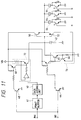
piezoelectric vibrating elements 64 in which driveelectrodes 61 are arranged with apiezoelectric material 63 interposed therebetween and in whichcommon electrodes 62 are arranged with apiezoelectric material 63 interposed therebetween, both electrodes and piezoelectric materials extending parallel to the expanding direction, as shown in Figure 10. - That is, in Figure 11,
reference numeral 72 designates a variable time constant adjusting unit for setting the pressure producing chamber expansion speed. If the signal from thedata judging unit 40 indicates that the print data includes only text data, the first time constant that is longer than the natural vibration cycle of the piezoelectric vibratingelement 64 is set, whereas if the print data includes only graphics image data, the second time constant that is longer than the first time constant is set.Reference numeral 73 designates a fixed time constant adjusting unit for setting the pressure producing chamber contracting speed. The fixed time constant is a time longer than the natural vibration cycle of the piezoelectric vibratingelement 64 in this embodiment. - The piezoelectric vibrating
elements 64 have first terminals thereof connected to thecurrent amplifying transistors constant adjusting unit 73 is operative, and therefore the common connecting terminal side of the piezoelectric vibratingelement 64 is maintained at a fixed level of substantially 0 (volt). As a result, all the piezoelectric vibratingelements 64 are discharged through the diodes D to substantially zero the applied voltage. - Thus, when the print auxiliary signal S1 goes low, only the piezoelectric vibrating
element 64 connected to the transistor T that has been turned on by the print signal is discharged through the transistor T, thereby causing the correspondingpressure producing chamber 5 to be expanded. - As a result of the above construction, the
pressure producing chamber 5 is caused to expand during the time the piezoelectric vibratingelement 64 is being charged, whereas the voltage applied to the piezoelectric vibratingelement 64 becomes substantially zero during the time the piezoelectric vibratingelement 64 is being discharged, so that an ink droplet is jetted when thepressure producing chamber 5 being contracted. Therefore, by setting the time constant of the variable timeconstant adjusting unit 72 to a long interval in response to the signal from thedata judging unit 40 in the case of printing image data and to a short interval in the case of printing text data, the volume of the ink droplet can be adjusted with the ink droplet ejection speed maintained at a fixed level in a manner similar to that of the above-mentioned embodiment. - The pressure producing chamber expansion speed is set to two levels in the above embodiments. If such speed is adjusted to three or more levels in accordance with the density of an image, a more subtle density adjustment can be given to the image data. That is, if an image has a high dot density, the size of an ink droplet can be adjusted to be smaller, whereas if an image has a low dot density, a dot containing a larger amount of ink is used for the printing. As a result, a uniform density can be maintained over the entire part of the image.
- As described in the foregoing, the invention is characterized as adjusting the volume of an ink droplet without changing the ink droplet ejection speed. This operation can be performed by ejection an ink droplet with the pressure producing chamber in an initial condition expanded to a predetermined volume over a time which is longer than the natural vibration cycle of the piezoelectric vibrating element and which corresponds to the size of the ink droplet to be ejected, by maintaining the pressure producing chamber as expanded for a predetermined interval with the expansion start time as a reference, and then by contracting the pressure producing chamber to the initial condition over a predetermined time that is longer than the natural vibration cycle of the piezoelectric vibrating element in a method for driving an ink jet recording head having not only pressure producing chambers communicating with nozzle openings but also piezoelectric vibrating elements for expanding and contracting the pressure producing chambers. As a result of the above operation, production of wrinkles can be prevented without impairing the print quality by minimizing the wetting of the recording paper at the time of printing image data.
Claims (5)
- A method for driving an ink jet recording head having a pressure producing chamber communicating with a nozzle opening and a piezoelectric vibrating element for expanding and contracting the pressure producing chamber, the method comprising the steps of:
expanding the pressure producing chamber under an initial condition to a predetermined volume over a first time period, the first time period being longer than a natural vibration cycle of the piezoelectric vibrating element and corresponding to a size of an ink droplet to be ejected;
maintaining the pressure producing chamber as expanded for a predetermined second period of time with an expansion start time as a reference; and
then contracting the pressure producing chamber to the initial condition over a predetermined third time period longer than the natural vibration cycle of the piezoelectric vibrating element, so that the ink droplet is ejected. - An apparatus for driving an ink jet recording head having a pressure producing chamber (5) communicating with a nozzle opening (2) and a piezoelectric vibrating element (14;64) for expanding and contracting the pressure producing chamber (5), especially according to claim 1, the apparatus comprising:
drive signal generating means for cyclically generating a first signal for expanding the pressure producing chamber (5) under an initial condition to a first period of time being longer than a natural vibration cycle of the piezoelectric vibrating element (14;64) and being suitable for forming a desired size of ink droplet, a second signal for maintaining the pressure producing chamber (5) as expanded for a predetermined second period of time with an output start time of the first signal as a reference, and a third signal for contracting the pressure producing chamber (5) to the initial condition over a predetermined third period of time longer than the natural vibration cycle of the piezoelectric vibrating element (14;64); and
means for selectively applying a drive signal from the drive signal generating means to the piezoelectric vibrating element (14;64); wherein
a time period during which the first signal is produced is varied in accordance with the size of the ink droplet to be ejected. - The apparatus for driving an ink jet recording head according to claim 2, further comprising data judging means (40) for judging whether or not data inputted to a print buffer includes graphics image data, and wherein the time for producing the first signal is set to a shorter value in the case of printing text data and to a longer value in the case of printing graphics image data in accordance with a signal from the data judging means (40).
- The apparatus for driving an ink jet recording head according to claim 2 or 3, wherein the first, second and third signals are first, second and third voltage wave-forms , respectively, and the drive signal is a voltage signal.
- The apparatus for driving an ink jet recording head according to claim 4, wherein the drive voltage signal generating means comprises a charging and discharging circuit comprising variable resistor means and capacitor (47), the time for producing the first voltage wave-form being adjusted by changing value of the variable resistor means.
Applications Claiming Priority (4)
| Application Number | Priority Date | Filing Date | Title |
|---|---|---|---|
| JP1021693 | 1993-01-25 | ||
| JP10216/93 | 1993-01-25 | ||
| JP345355/93 | 1993-12-21 | ||
| JP34535593A JP3292223B2 (en) | 1993-01-25 | 1993-12-21 | Driving method and apparatus for inkjet recording head |
Publications (3)
| Publication Number | Publication Date |
|---|---|
| EP0608835A2 true EP0608835A2 (en) | 1994-08-03 |
| EP0608835A3 EP0608835A3 (en) | 1995-02-22 |
| EP0608835B1 EP0608835B1 (en) | 1997-10-01 |
Family
ID=26345450
Family Applications (1)
| Application Number | Title | Priority Date | Filing Date |
|---|---|---|---|
| EP94101060A Expired - Lifetime EP0608835B1 (en) | 1993-01-25 | 1994-01-25 | Method and apparatus for driving ink jet recording head |
Country Status (4)
| Country | Link |
|---|---|
| US (1) | US5552809A (en) |
| EP (1) | EP0608835B1 (en) |
| JP (1) | JP3292223B2 (en) |
| DE (1) | DE69405885T2 (en) |
Cited By (13)
| Publication number | Priority date | Publication date | Assignee | Title |
|---|---|---|---|---|
| EP0738602A2 (en) * | 1995-04-21 | 1996-10-23 | Seiko Epson Corporation | Ink jet print head |
| EP0738598A2 (en) * | 1995-04-19 | 1996-10-23 | Seiko Epson Corporation | Drive device for jetting ink droplets |
| EP0738601A2 (en) * | 1995-04-20 | 1996-10-23 | Seiko Epson Corporation | An ink jet head, a printing apparatus using the ink jet head, and a method of controlling it |
| EP0718102A3 (en) * | 1994-12-20 | 1997-04-02 | Sharp Kk | Compact ink jet head with deformable structure for ink discharge with great force |
| WO1997018952A1 (en) * | 1995-11-23 | 1997-05-29 | Xaar Technology Limited | Operation of pulsed droplet deposition apparatus |
| US5666141A (en) * | 1993-07-13 | 1997-09-09 | Sharp Kabushiki Kaisha | Ink jet head and a method of manufacturing thereof |
| DE19803467A1 (en) * | 1997-01-30 | 1998-08-06 | Nec Corp | Arrangement for ejecting ink droplets |
| EP0925922A1 (en) * | 1997-12-26 | 1999-06-30 | Nec Corporation | Ink jet recording head controlling diameter of an ink droplet |
| US6000785A (en) * | 1995-04-20 | 1999-12-14 | Seiko Epson Corporation | Ink jet head, a printing apparatus using the ink jet head, and a control method therefor |
| WO2000044564A1 (en) * | 1999-01-28 | 2000-08-03 | Nec Corporation | Ink jet recording head driving method and ink jet recording device |
| US6217159B1 (en) | 1995-04-21 | 2001-04-17 | Seiko Epson Corporation | Ink jet printing device |
| CN101590738A (en) * | 2008-05-30 | 2009-12-02 | 精工爱普生株式会社 | Fluid ejection apparatus |
| EP2127882A1 (en) * | 2008-05-30 | 2009-12-02 | Seiko Epson Corporation | Fluid ejecting apparatus |
Families Citing this family (38)
| Publication number | Priority date | Publication date | Assignee | Title |
|---|---|---|---|---|
| JP3250596B2 (en) * | 1994-07-01 | 2002-01-28 | セイコーエプソン株式会社 | Ink jet recording device |
| JPH08336970A (en) * | 1995-04-14 | 1996-12-24 | Seiko Epson Corp | Ink-jet type recording device |
| JP3674998B2 (en) * | 1995-09-29 | 2005-07-27 | ソニー株式会社 | Printer device |
| JP2870459B2 (en) | 1995-10-09 | 1999-03-17 | 日本電気株式会社 | INK JET RECORDING APPARATUS AND MANUFACTURING METHOD THEREOF |
| JP2783225B2 (en) * | 1995-12-05 | 1998-08-06 | 日本電気株式会社 | Ink jet head device |
| JPH1016211A (en) * | 1996-07-05 | 1998-01-20 | Seiko Epson Corp | Ink jet recorder |
| US6045209A (en) * | 1996-08-20 | 2000-04-04 | Brother Kogyo Kabushiki Kaisha | Circuit for driving ink-jet head |
| US6002549A (en) * | 1996-11-01 | 1999-12-14 | Seagate Technology, Inc. | Dither microactors for stiction release in magnetic disc drives |
| US6052251A (en) * | 1996-11-01 | 2000-04-18 | Seagate Technology, Inc. | Actuator arm integrated piezoelectric microactuator |
| USRE38340E1 (en) * | 1996-11-04 | 2003-12-02 | Seagate Technology Llc | Multi-point bending of bars during fabrication of magnetic recording heads |
| WO1998027547A1 (en) * | 1996-12-16 | 1998-06-25 | Seagate Technology, Inc. | Bimorph piezoelectric microactuator head and flexure assembly |
| JP3271540B2 (en) * | 1997-02-06 | 2002-04-02 | ミノルタ株式会社 | Ink jet recording device |
| WO1998044488A1 (en) | 1997-03-31 | 1998-10-08 | Seagate Technology, Inc. | Flexure microactuator |
| US6396667B1 (en) | 1997-06-24 | 2002-05-28 | Seagate Technology Llc | Electromagnetic disc drive microactuator and suspension |
| US6362542B1 (en) | 1997-08-15 | 2002-03-26 | Seagate Technology Llc | Piezoelectric microactuator for precise head positioning |
| US6269687B1 (en) | 1997-09-22 | 2001-08-07 | Seagate Technology Llc | Force sensing slider |
| US6067215A (en) * | 1997-10-09 | 2000-05-23 | Seagate Technology, Inc. | Magnetic shielding for electromagnetic microactuator |
| US6163434A (en) * | 1997-10-23 | 2000-12-19 | Seagate Technology Llc | Piezoresistive position sensors embedded in disc drive microactuator |
| US6157522A (en) * | 1998-04-07 | 2000-12-05 | Seagate Technology Llc | Suspension-level microactuator |
| US6215629B1 (en) | 1998-04-16 | 2001-04-10 | Seagate Technology Llc | Unitary synchronous flexure microactuator |
| US6078473A (en) * | 1998-05-13 | 2000-06-20 | Seagate Technology, Inc. | Gimbal flexure for use with microactuator |
| US6414822B1 (en) | 1998-06-11 | 2002-07-02 | Seagate Technology Llc | Magnetic microactuator |
| US6359758B1 (en) | 1998-06-11 | 2002-03-19 | Seagate Technology, Llc | Rigid body microactuator having elastic joint attachment |
| JP3223891B2 (en) * | 1998-10-20 | 2001-10-29 | 日本電気株式会社 | Drive circuit for inkjet recording head |
| JP2000127390A (en) * | 1998-10-30 | 2000-05-09 | Nec Corp | Driving method for ink jet recording head |
| US6233124B1 (en) | 1998-11-18 | 2001-05-15 | Seagate Technology Llc | Piezoelectric microactuator suspension assembly with improved stroke length |
| JP3371331B2 (en) * | 1998-12-14 | 2003-01-27 | セイコーエプソン株式会社 | Ink jet recording head and method of manufacturing the same |
| US6268984B1 (en) | 1999-01-22 | 2001-07-31 | Seagate Technology Llc | Magnet configuration for head-level microactuator |
| JP2001260358A (en) * | 2000-03-17 | 2001-09-25 | Nec Corp | Apparatus and method for driving ink jet recording head |
| JP2003291367A (en) * | 2002-04-02 | 2003-10-14 | Sony Corp | Device for displaying remaining amount of liquid |
| JP2004314612A (en) * | 2003-03-28 | 2004-11-11 | Kyocera Corp | Driving method of piezoelectric ink-jet head |
| US7281778B2 (en) | 2004-03-15 | 2007-10-16 | Fujifilm Dimatix, Inc. | High frequency droplet ejection device and method |
| US8491076B2 (en) | 2004-03-15 | 2013-07-23 | Fujifilm Dimatix, Inc. | Fluid droplet ejection devices and methods |
| KR20070087223A (en) | 2004-12-30 | 2007-08-27 | 후지필름 디마틱스, 인크. | Ink jet printing |
| US7988247B2 (en) | 2007-01-11 | 2011-08-02 | Fujifilm Dimatix, Inc. | Ejection of drops having variable drop size from an ink jet printer |
| JP2009226922A (en) * | 2008-02-26 | 2009-10-08 | Seiko Epson Corp | Printing control system, printing request terminal, printer, and printing control method |
| US8393702B2 (en) | 2009-12-10 | 2013-03-12 | Fujifilm Corporation | Separation of drive pulses for fluid ejector |
| JP5698595B2 (en) * | 2011-04-28 | 2015-04-08 | 理想科学工業株式会社 | Image recording device |
Citations (6)
| Publication number | Priority date | Publication date | Assignee | Title |
|---|---|---|---|---|
| US4471363A (en) * | 1980-08-25 | 1984-09-11 | Epson Corporation | Method and apparatus for driving an ink jet printer head |
| JPS59176055A (en) * | 1983-03-25 | 1984-10-05 | Konishiroku Photo Ind Co Ltd | On-demand type ink jet recording apparatus |
| EP0159188A2 (en) * | 1984-04-16 | 1985-10-23 | Dataproducts Corporation | Method for operating an ink jet device to obtain high resolution printing |
| US4561025A (en) * | 1983-08-31 | 1985-12-24 | Nec Corporation | Ink-jet recording system capable of recording a half-tone |
| JPH02192947A (en) * | 1988-10-14 | 1990-07-30 | Fuji Electric Co Ltd | Drive method for ink jet recording head |
| JPH03193456A (en) * | 1989-12-25 | 1991-08-23 | Seiko Epson Corp | Ink-jet head |
Family Cites Families (3)
| Publication number | Priority date | Publication date | Assignee | Title |
|---|---|---|---|---|
| JPS59136266A (en) * | 1983-01-25 | 1984-08-04 | Nec Corp | Drive circuit for ink jet head |
| US5146236A (en) * | 1989-12-14 | 1992-09-08 | Ricoh Company, Ltd. | Ink jet record apparatus |
| US5510816A (en) * | 1991-11-07 | 1996-04-23 | Seiko Epson Corporation | Method and apparatus for driving ink jet recording head |
-
1993
- 1993-12-21 JP JP34535593A patent/JP3292223B2/en not_active Expired - Lifetime
-
1994
- 1994-01-25 EP EP94101060A patent/EP0608835B1/en not_active Expired - Lifetime
- 1994-01-25 DE DE69405885T patent/DE69405885T2/en not_active Expired - Fee Related
- 1994-01-25 US US08/186,378 patent/US5552809A/en not_active Expired - Lifetime
Patent Citations (6)
| Publication number | Priority date | Publication date | Assignee | Title |
|---|---|---|---|---|
| US4471363A (en) * | 1980-08-25 | 1984-09-11 | Epson Corporation | Method and apparatus for driving an ink jet printer head |
| JPS59176055A (en) * | 1983-03-25 | 1984-10-05 | Konishiroku Photo Ind Co Ltd | On-demand type ink jet recording apparatus |
| US4561025A (en) * | 1983-08-31 | 1985-12-24 | Nec Corporation | Ink-jet recording system capable of recording a half-tone |
| EP0159188A2 (en) * | 1984-04-16 | 1985-10-23 | Dataproducts Corporation | Method for operating an ink jet device to obtain high resolution printing |
| JPH02192947A (en) * | 1988-10-14 | 1990-07-30 | Fuji Electric Co Ltd | Drive method for ink jet recording head |
| JPH03193456A (en) * | 1989-12-25 | 1991-08-23 | Seiko Epson Corp | Ink-jet head |
Non-Patent Citations (3)
| Title |
|---|
| PATENT ABSTRACTS OF JAPAN vol. 14, no. 478 (M-1036) 18 October 1990 & JP-A-02 192 947 (FUJI ELECTRIC CO LTD) 30 July 1990 * |
| PATENT ABSTRACTS OF JAPAN vol. 15, no. 452 (M-1180) 18 November 1991 & JP-A-03 193 456 (SEIKO EPSON CORP) 23 August 1991 * |
| PATENT ABSTRACTS OF JAPAN vol. 9, no. 34 (M-357) (1757) 14 February 1985 & JP-A-59 176 055 (KONISHIROKU SHASHIN KOGYO K.K.) 5 October 1984 * |
Cited By (25)
| Publication number | Priority date | Publication date | Assignee | Title |
|---|---|---|---|---|
| US5666141A (en) * | 1993-07-13 | 1997-09-09 | Sharp Kabushiki Kaisha | Ink jet head and a method of manufacturing thereof |
| US5825383A (en) * | 1994-12-20 | 1998-10-20 | Sharp Kabushiki Kaisha | Ink jet head compact and allowing ink to be discharged with great force by using deformable structure |
| EP0718102A3 (en) * | 1994-12-20 | 1997-04-02 | Sharp Kk | Compact ink jet head with deformable structure for ink discharge with great force |
| EP0738598A2 (en) * | 1995-04-19 | 1996-10-23 | Seiko Epson Corporation | Drive device for jetting ink droplets |
| US5980015A (en) * | 1995-04-19 | 1999-11-09 | Seiko Epson Corporation | Ink jet printing head embodiment with drive signal circuit outputting different drive signals each printing period and with selecting circuit applying one of the signals to piezoelectric elements that expand and contract pressure generating chambers |
| EP0738598A3 (en) * | 1995-04-19 | 1997-07-09 | Seiko Epson Corp | Drive device for jetting ink droplets |
| EP0738601A2 (en) * | 1995-04-20 | 1996-10-23 | Seiko Epson Corporation | An ink jet head, a printing apparatus using the ink jet head, and a method of controlling it |
| US6000785A (en) * | 1995-04-20 | 1999-12-14 | Seiko Epson Corporation | Ink jet head, a printing apparatus using the ink jet head, and a control method therefor |
| EP0738601A3 (en) * | 1995-04-20 | 1997-07-02 | Seiko Epson Corp | An ink jet head, a printing apparatus using the ink jet head, and a method of controlling it |
| US5894316A (en) * | 1995-04-20 | 1999-04-13 | Seiko Epson Corporation | Ink jet head with diaphragm having varying compliance or stepped opposing wall |
| US6217159B1 (en) | 1995-04-21 | 2001-04-17 | Seiko Epson Corporation | Ink jet printing device |
| EP0738602A2 (en) * | 1995-04-21 | 1996-10-23 | Seiko Epson Corporation | Ink jet print head |
| US6382754B1 (en) | 1995-04-21 | 2002-05-07 | Seiko Epson Corporation | Ink jet printing device |
| EP0738602A3 (en) * | 1995-04-21 | 1997-06-11 | Seiko Epson Corp | Ink jet print head |
| WO1997018952A1 (en) * | 1995-11-23 | 1997-05-29 | Xaar Technology Limited | Operation of pulsed droplet deposition apparatus |
| US6010202A (en) * | 1995-11-23 | 2000-01-04 | Xaar Technology Limited | Operation of pulsed droplet deposition apparatus |
| CN1086636C (en) * | 1995-11-23 | 2002-06-26 | 萨尔技术有限公司 | Operation of pulsed droplet deposition apparatus |
| DE19803467C2 (en) * | 1997-01-30 | 2000-02-10 | Nec Corp | Device for ejecting ink droplets |
| DE19803467A1 (en) * | 1997-01-30 | 1998-08-06 | Nec Corp | Arrangement for ejecting ink droplets |
| US6241345B1 (en) | 1997-12-26 | 2001-06-05 | Nec Corporation | Ink jet recording head controlling diameter of an ink droplet |
| EP0925922A1 (en) * | 1997-12-26 | 1999-06-30 | Nec Corporation | Ink jet recording head controlling diameter of an ink droplet |
| WO2000044564A1 (en) * | 1999-01-28 | 2000-08-03 | Nec Corporation | Ink jet recording head driving method and ink jet recording device |
| US6705696B1 (en) * | 1999-01-28 | 2004-03-16 | Fuji Xerox Co., Ltd | Method of driving inkjet recording head and inkjet recording apparatus |
| CN101590738A (en) * | 2008-05-30 | 2009-12-02 | 精工爱普生株式会社 | Fluid ejection apparatus |
| EP2127882A1 (en) * | 2008-05-30 | 2009-12-02 | Seiko Epson Corporation | Fluid ejecting apparatus |
Also Published As
| Publication number | Publication date |
|---|---|
| DE69405885D1 (en) | 1997-11-06 |
| JPH06316074A (en) | 1994-11-15 |
| JP3292223B2 (en) | 2002-06-17 |
| EP0608835B1 (en) | 1997-10-01 |
| EP0608835A3 (en) | 1995-02-22 |
| DE69405885T2 (en) | 1998-04-09 |
| US5552809A (en) | 1996-09-03 |
Similar Documents
| Publication | Publication Date | Title |
|---|---|---|
| EP0608835B1 (en) | Method and apparatus for driving ink jet recording head | |
| US6290315B1 (en) | Method of driving an ink jet recording head | |
| KR100741542B1 (en) | an Image Formation Apparatus | |
| EP1515854B1 (en) | Head control device and image recording apparatus | |
| JP3763200B2 (en) | Inkjet recording device | |
| US7178893B2 (en) | Head controller, inkjet recording apparatus, and image recording apparatus that prevent degradation in image quality due to environmental temperature changes | |
| JP3319733B2 (en) | INK JET RECORDING APPARATUS AND CONTROL METHOD THEREOF | |
| JP2002337333A (en) | Ink jet recorder and method for driving ink jet recording head for use therein | |
| JP2004249686A (en) | Liquid jet device and liquid droplet discharge control method therefor | |
| JP2000218786A (en) | Ink-jet recording apparatus and driving method therefor | |
| JPH11157056A (en) | Ink jet printer, and device and method for driving ink jet printer recording head | |
| JP3988130B2 (en) | Liquid ejector | |
| JP4342744B2 (en) | Head drive device and ink jet recording apparatus | |
| JP2001179964A (en) | Drive controller for head and ink jet recorder | |
| JP4956901B2 (en) | Liquid ejector | |
| JP2004160903A (en) | Head driving controller and image recorder | |
| JP2002254625A (en) | Ink jet recording device | |
| JP3959704B2 (en) | Liquid ejector | |
| JP3302401B2 (en) | Ink jet driving apparatus and ink jet driving method | |
| JPH10250068A (en) | Ink jet recorder | |
| JP2003094639A (en) | Ink jet printer | |
| JPH10286948A (en) | Ink jet recording device | |
| JPH10305575A (en) | Ink jet recorder | |
| JPH09193371A (en) | Ink jet recording device | |
| JP4385843B2 (en) | Electrostatic inkjet head driving method and inkjet printer |
Legal Events
| Date | Code | Title | Description |
|---|---|---|---|
| PUAI | Public reference made under article 153(3) epc to a published international application that has entered the european phase |
Free format text: ORIGINAL CODE: 0009012 |
|
| AK | Designated contracting states |
Kind code of ref document: A2 Designated state(s): DE FR GB IT |
|
| PUAL | Search report despatched |
Free format text: ORIGINAL CODE: 0009013 |
|
| AK | Designated contracting states |
Kind code of ref document: A3 Designated state(s): DE FR GB IT |
|
| 17P | Request for examination filed |
Effective date: 19950405 |
|
| 17Q | First examination report despatched |
Effective date: 19960315 |
|
| GRAG | Despatch of communication of intention to grant |
Free format text: ORIGINAL CODE: EPIDOS AGRA |
|
| GRAH | Despatch of communication of intention to grant a patent |
Free format text: ORIGINAL CODE: EPIDOS IGRA |
|
| GRAH | Despatch of communication of intention to grant a patent |
Free format text: ORIGINAL CODE: EPIDOS IGRA |
|
| GRAA | (expected) grant |
Free format text: ORIGINAL CODE: 0009210 |
|
| AK | Designated contracting states |
Kind code of ref document: B1 Designated state(s): DE FR GB IT |
|
| ITF | It: translation for a ep patent filed |
Owner name: BUZZI, NOTARO&ANTONIELLI D'OULX |
|
| REF | Corresponds to: |
Ref document number: 69405885 Country of ref document: DE Date of ref document: 19971106 |
|
| ET | Fr: translation filed | ||
| PLBE | No opposition filed within time limit |
Free format text: ORIGINAL CODE: 0009261 |
|
| STAA | Information on the status of an ep patent application or granted ep patent |
Free format text: STATUS: NO OPPOSITION FILED WITHIN TIME LIMIT |
|
| 26N | No opposition filed | ||
| REG | Reference to a national code |
Ref country code: GB Ref legal event code: IF02 |
|
| PGFP | Annual fee paid to national office [announced via postgrant information from national office to epo] |
Ref country code: DE Payment date: 20080117 Year of fee payment: 15 |
|
| PG25 | Lapsed in a contracting state [announced via postgrant information from national office to epo] |
Ref country code: DE Free format text: LAPSE BECAUSE OF NON-PAYMENT OF DUE FEES Effective date: 20090801 |
|
| PGFP | Annual fee paid to national office [announced via postgrant information from national office to epo] |
Ref country code: IT Payment date: 20120116 Year of fee payment: 19 |
|
| PGFP | Annual fee paid to national office [announced via postgrant information from national office to epo] |
Ref country code: GB Payment date: 20130123 Year of fee payment: 20 Ref country code: FR Payment date: 20130204 Year of fee payment: 20 |
|
| REG | Reference to a national code |
Ref country code: GB Ref legal event code: PE20 Expiry date: 20140124 |
|
| PG25 | Lapsed in a contracting state [announced via postgrant information from national office to epo] |
Ref country code: GB Free format text: LAPSE BECAUSE OF EXPIRATION OF PROTECTION Effective date: 20140124 |