EP0607941A2 - Method and apparatus for detecting fluorescence in sterilization monitors - Google Patents
Method and apparatus for detecting fluorescence in sterilization monitors Download PDFInfo
- Publication number
- EP0607941A2 EP0607941A2 EP94100716A EP94100716A EP0607941A2 EP 0607941 A2 EP0607941 A2 EP 0607941A2 EP 94100716 A EP94100716 A EP 94100716A EP 94100716 A EP94100716 A EP 94100716A EP 0607941 A2 EP0607941 A2 EP 0607941A2
- Authority
- EP
- European Patent Office
- Prior art keywords
- target
- wavelength
- vial
- fluorescing
- light
- Prior art date
- Legal status (The legal status is an assumption and is not a legal conclusion. Google has not performed a legal analysis and makes no representation as to the accuracy of the status listed.)
- Withdrawn
Links
- 238000000034 method Methods 0.000 title claims description 22
- 238000004659 sterilization and disinfection Methods 0.000 title abstract description 30
- 230000001954 sterilising effect Effects 0.000 title description 28
- 230000005284 excitation Effects 0.000 claims abstract description 35
- 239000000463 material Substances 0.000 claims abstract description 14
- 238000005259 measurement Methods 0.000 claims description 65
- 239000013077 target material Substances 0.000 claims description 33
- 239000012925 reference material Substances 0.000 claims description 32
- 230000004044 response Effects 0.000 claims description 10
- 239000000758 substrate Substances 0.000 claims description 6
- 229910052693 Europium Inorganic materials 0.000 claims description 2
- 239000004698 Polyethylene Substances 0.000 claims description 2
- 239000000853 adhesive Substances 0.000 claims description 2
- 230000001070 adhesive effect Effects 0.000 claims description 2
- DXNVUKXMTZHOTP-UHFFFAOYSA-N dialuminum;dimagnesium;barium(2+);oxygen(2-) Chemical compound [O-2].[O-2].[O-2].[O-2].[O-2].[O-2].[O-2].[Mg+2].[Mg+2].[Al+3].[Al+3].[Ba+2].[Ba+2] DXNVUKXMTZHOTP-UHFFFAOYSA-N 0.000 claims description 2
- OGPBJKLSAFTDLK-UHFFFAOYSA-N europium atom Chemical compound [Eu] OGPBJKLSAFTDLK-UHFFFAOYSA-N 0.000 claims description 2
- -1 polyethylene Polymers 0.000 claims description 2
- 229920000573 polyethylene Polymers 0.000 claims description 2
- 238000012360 testing method Methods 0.000 abstract description 28
- 229910052736 halogen Inorganic materials 0.000 abstract description 9
- 150000002367 halogens Chemical class 0.000 abstract description 9
- 238000005286 illumination Methods 0.000 abstract description 4
- 238000011156 evaluation Methods 0.000 abstract description 2
- 230000008569 process Effects 0.000 description 7
- 230000009977 dual effect Effects 0.000 description 6
- 238000004519 manufacturing process Methods 0.000 description 6
- 238000010586 diagram Methods 0.000 description 5
- 238000012544 monitoring process Methods 0.000 description 5
- 238000004458 analytical method Methods 0.000 description 4
- 230000006641 stabilisation Effects 0.000 description 4
- 238000011105 stabilization Methods 0.000 description 4
- 239000011149 active material Substances 0.000 description 3
- 238000011534 incubation Methods 0.000 description 3
- IAYPIBMASNFSPL-UHFFFAOYSA-N Ethylene oxide Chemical compound C1CO1 IAYPIBMASNFSPL-UHFFFAOYSA-N 0.000 description 2
- 230000008859 change Effects 0.000 description 2
- 238000010276 construction Methods 0.000 description 2
- 230000000694 effects Effects 0.000 description 2
- 238000001914 filtration Methods 0.000 description 2
- 230000007257 malfunction Effects 0.000 description 2
- 230000005855 radiation Effects 0.000 description 2
- 230000005540 biological transmission Effects 0.000 description 1
- 239000000090 biomarker Substances 0.000 description 1
- 230000000052 comparative effect Effects 0.000 description 1
- 238000001917 fluorescence detection Methods 0.000 description 1
- 239000007850 fluorescent dye Substances 0.000 description 1
- 208000015181 infectious disease Diseases 0.000 description 1
- 238000012545 processing Methods 0.000 description 1
- 230000001105 regulatory effect Effects 0.000 description 1
- 238000012163 sequencing technique Methods 0.000 description 1
- 239000007787 solid Substances 0.000 description 1
- 238000001228 spectrum Methods 0.000 description 1
- 230000004936 stimulating effect Effects 0.000 description 1
- 239000000126 substance Substances 0.000 description 1
- 238000001356 surgical procedure Methods 0.000 description 1
- 230000004083 survival effect Effects 0.000 description 1
Images


Classifications
-
- G—PHYSICS
- G01—MEASURING; TESTING
- G01N—INVESTIGATING OR ANALYSING MATERIALS BY DETERMINING THEIR CHEMICAL OR PHYSICAL PROPERTIES
- G01N21/00—Investigating or analysing materials by the use of optical means, i.e. using sub-millimetre waves, infrared, visible or ultraviolet light
- G01N21/17—Systems in which incident light is modified in accordance with the properties of the material investigated
- G01N21/25—Colour; Spectral properties, i.e. comparison of effect of material on the light at two or more different wavelengths or wavelength bands
- G01N21/27—Colour; Spectral properties, i.e. comparison of effect of material on the light at two or more different wavelengths or wavelength bands using photo-electric detection ; circuits for computing concentration
- G01N21/274—Calibration, base line adjustment, drift correction
-
- A—HUMAN NECESSITIES
- A61—MEDICAL OR VETERINARY SCIENCE; HYGIENE
- A61L—METHODS OR APPARATUS FOR STERILISING MATERIALS OR OBJECTS IN GENERAL; DISINFECTION, STERILISATION OR DEODORISATION OF AIR; CHEMICAL ASPECTS OF BANDAGES, DRESSINGS, ABSORBENT PADS OR SURGICAL ARTICLES; MATERIALS FOR BANDAGES, DRESSINGS, ABSORBENT PADS OR SURGICAL ARTICLES
- A61L2/00—Methods or apparatus for disinfecting or sterilising materials or objects other than foodstuffs or contact lenses; Accessories therefor
- A61L2/26—Accessories or devices or components used for biocidal treatment
- A61L2/28—Devices for testing the effectiveness or completeness of sterilisation, e.g. indicators which change colour
-
- C—CHEMISTRY; METALLURGY
- C12—BIOCHEMISTRY; BEER; SPIRITS; WINE; VINEGAR; MICROBIOLOGY; ENZYMOLOGY; MUTATION OR GENETIC ENGINEERING
- C12M—APPARATUS FOR ENZYMOLOGY OR MICROBIOLOGY; APPARATUS FOR CULTURING MICROORGANISMS FOR PRODUCING BIOMASS, FOR GROWING CELLS OR FOR OBTAINING FERMENTATION OR METABOLIC PRODUCTS, i.e. BIOREACTORS OR FERMENTERS
- C12M37/00—Means for sterilizing, maintaining sterile conditions or avoiding chemical or biological contamination
- C12M37/06—Means for testing the completeness of the sterilization
-
- G—PHYSICS
- G01—MEASURING; TESTING
- G01N—INVESTIGATING OR ANALYSING MATERIALS BY DETERMINING THEIR CHEMICAL OR PHYSICAL PROPERTIES
- G01N21/00—Investigating or analysing materials by the use of optical means, i.e. using sub-millimetre waves, infrared, visible or ultraviolet light
- G01N21/62—Systems in which the material investigated is excited whereby it emits light or causes a change in wavelength of the incident light
- G01N21/63—Systems in which the material investigated is excited whereby it emits light or causes a change in wavelength of the incident light optically excited
- G01N21/64—Fluorescence; Phosphorescence
- G01N2021/6417—Spectrofluorimetric devices
- G01N2021/6421—Measuring at two or more wavelengths
Definitions
- the present invention relates generally to apparatus and methods for detecting fluorescence of a luminescent material and, more particularly, to such methods and apparatus used in sterilization monitors.
- the equipment, instruments or materials that are to be sterilized may be subjected to the necessary parameters to achieve sterilization including the interrelated parameters of time, temperature, steam, dry heat, chemicals such as ethylene oxide gas or radiation dosage.
- the sterilization process is designed to kill living organisms which might otherwise contaminate the goods being sterilized.
- Steam sterilization ranges from 121 - 132 degrees Centigrade with exposure times of three minutes at 132 degrees Centigrade to 30 minutes at 121 degrees Centigrade.
- Ethylene oxide sterilization ranges from 30 to 65 degrees Centigrade with exposure times of one hour to four hours.
- Dry heat sterilization typically is two hours at 180 degrees Centigrade.
- a small vial, or other container is inserted into the sterilization unit in order to check upon the completeness of the sterilization process.
- the vial typically will contain living organisms that are provided nourishment and an environment for rapid growth after being subjected to the sterilization process.
- the vial can then be checked for growth of the organism after a incubation period.
- the incubation allows any organism surviving the sterilization process to grow to a detectable level. Survival of the organism indicates an inadequate sterilization process.
- a substrate material is added to the vial for the living organisms to react with causing the substrate to change color.
- a potentially luminescent substrate material is added to the vial for the living organisms to react with.
- a fluorescent light typically an ultraviolet wavelength light, which excites the invisible to the naked eye fluorescence to appear as visible light.
- the appearance of visible light in the vial when subjected to an exciting fluorescent light would indicate inadequate sterilization, due at least in part to a shortened time period required for the growth of the living organisms, more automated fluorescence detectors are to be utilized.
- fluorescence from the luminescent substrate in the vial be measured at a very low threshold, approximately 0.1 picowatt.
- United States Patent No. 5,073,488, Matner, Foltz and Woodson, Rapid Method For Determining Efficacy Of A Sterilization Cycle And Rapid Read-out Biological Indicator discloses a method of developing the fluorescing indicator used in a fluorescence detection apparatus.
- the ultraviolet light source typically used tends to be very unstable due in part to variances in the gas ionization at one or more of the cathodes located at each end of the ultraviolet light source. Further, localized heat variations and emission fluctuations cause the output of the ultraviolet light source (lamp) to contain many independently varying harmonics of the power line frequency. The overall crest-to-trough ratio fluctuates similarly. The use of DC coupled amplifiers with low pass filtering to remove these fluctuations is unacceptable because the DC drift would be well in excess of the signal level being measured.
- Prior art fluorescence detectors sometimes utilize dual channels to attempt to adjust for these fluctuations.
- a further problem exists when dual channels are utilized or when the target measurement is taken at a different time from the reference. Since, the signal being measured is so small, minor variations in components between dual channels, even with costly matched components, and between different times of measurement can result in a complete "swamping" of the signal to be measured. The result can easily be an inaccurate measurement.
- the "growth" period must be expanded (or not reduced) in order to ensure that living organisms, if present, will be detected.
- United States Patent No. 4,626,684, Landa discloses an apparatus for rapidly conducting fluorescence measurements.
- the electronics of the apparatus utilizes dual channels. One channel detects the fluorescence of the sample.
- the other channel detects the fluorescence of a reference.
- the "background" reference fluorescence is subtracted from the signal sample in order to account for the background.
- the dual channels must be exactly matched.
- United States Patent No. 4,668,868, Noller discloses a fluorescence detector for performing fluoroimmunoassays of biological specimens.
- the light energy from the sample is used to excite a photovoltaic cell.
- Temperature compensation is provided by a second photovoltaic cell from which light excitation is eliminated.
- a push button calibrator also used to provide a bias voltage from the voltaic cell with zero input signal which is memorized.
- a significant disadvantage of the system of Noller is the lack of a reference value. Since fluctuations in the intensity of stimulating radiation may greatly affect the amount of visible light output apparently perceived can vary greatly.
- the present invention provides an apparatus and method for detecting fluorescence to determine the relative fluorescence of a sterilization monitor vial.
- the apparatus and method provides for automated calibration to insure initial calibration, stabilization and accuracy within critical limits.
- automated operation of the apparatus and method of the present consists of three phases. Each phase must be successfully executed before the next can begin.
- the operator inserts a new and unused vial selected from the current production lot being used for sterilization monitoring.
- the unused vial has not been subjected to an incubation and accordingly no growth of the organisms has occurred.
- This vial then only gives a minimal fluorescence which is subject to the calibration in this step.
- the apparatus then calibrates the vial measurement signal to match the reference signal. At this point the new vial is removed and the unit remains in a standby status until test (target) vials are ready for analysis.
- test (target) vial is inserted into the apparatus.
- the excitation lamp is energized to full voltage, after a stabilization period, the vial light emissions are measured, compared with each other for stability, and the lamp voltage is compared with set up. If the vial measurements fall within a stable range and lamp voltage measurement is within specifications, the apparatus compares the average test vial emission with the calibration value. If the measured result is within the calibration value indicating that no active material is present in the test vial, an indicator is set. If the measured result is outside the calibration value plus a predetermined threshold value indicating that active material is still present in the vial a different indicator is set. If the various measurements are not stable, a warning signal is set.
- the present invention provides an apparatus for detecting fluorescence of an unknown target material being excitable at an excitation wavelength and fluorescing at a fluorescing wavelength.
- An energy source is arranged to excite both the target material and a reference material at approximately the excitation wavelength.
- a power supply supplies electrical power having an adjustable voltage to the energy source.
- An excitation filter is optically arranged between the energy source and both of the target material and the reference material, the excitation filter passing light energy at approximately the excitation wavelength.
- a reference detector is optically arranged to be responsive to and for detecting light emitted from the reference material at approximately the fluorescing wavelength.
- a target detector is optically arranged to be responsive to and for detecting light emitted from the target material at approximately the fluorescing wavelength.
- Reference measurement means generates a reference output in response to the reference detector means in order to determine the amount of fluorescence generated by the reference material.
- Target measurement means generates a target output in response to the target detector means in order to determine the amount of fluorescence generated by the target material.
- Reference calibration means is coupled to the reference measurement means and to the power supply means for varying the electrical voltage supplied to the energy source and for calibrating the reference output.
- Target calibration means is coupled to the target measurement means for calibrating the target output in response to a known target material.
- the apparatus may have the reference measurement means calibrated without a target material, then may have the target measurement means calibrated using the known target material, and then may have the target measurement means determine the fluorescence of the unknown target material.
- the reference detector is a photodiode.
- the apparatus has a first fluorescing wavelength filter optically arranged between the reference material and the photodiode of the reference detector means.
- the fluorescing first wavelength filter passes light energy at approximately the fluorescing wavelength.
- a second fluorescing wavelength filter is optically arranged between the target material and the photodiode of the target detector means.
- the second wavelength filter passes light energy at approximately the fluorescing wavelength.
- the present invention also provides a method for detecting fluorescence of an unknown target material being excitable at an excitation wavelength and fluorescing at a fluorescing wavelength in an apparatus having a reference material; an energy source arranged to excite both the target material and the reference material at approximately the excitation wavelength; power supply means for supplying electrical power having an adjustable voltage to the energy source; a reference detector means optically arranged to be responsive to the reference material at approximately the fluorescing wavelength; a target detector means optically arranged to be responsive to the target material at approximately the fluorescing wavelength; reference measurement means for generating a reference output in response to the reference detector means in order to determine the amount of fluorescence generated by the reference material; target measurement means for generating a target output in response to the target detector means in order to determine the amount of fluorescence generated by the target material.
- the method comprises the steps of calibrating the energy source and the reference measurement means without a target material; calibrating the target measurement means using the known target material; and measuring the unknown target material using the target measurement means to
- the method further comprises the steps of verifying that the energy source is operational; verifying that the reference measurement means is operational; and providing an alarm if the energy source or the reference measurement means is not operational.
- the method further comprises the steps of verifying that the target measurement means is operational; and providing an alarm if the energy source or the target measurement means is not operational.
- the preferred apparatus for detecting fluorescence is a fully automated instrument for determining of the relative fluorescence of a sterilization monitor vial.
- the light source for excitation of the fluorescent material is a halogen lamp held in a stable standby (warm) state, energized to full illumination only when a vial is inserted into a cavity in the instrument housing actuating a light switch. Excitation light from this halogen lamp is guided in two parallel light paths through light filters providing a selected wave length band to the vial and to a fluorescing reference film. Emitted light from the fluorescent film and the from the vial is guided onto separate detectors providing signals for evaluation by a programmed micro-processor. Results of the micro-processor program provide output information of the relative fluorescence and/or the apparatus performance. Normal output information is in the form of yes/no result signal indicated by green or red lights. It is possible to obtain specific values of light output from the vial. Further, the micro-processor provides self-calibration of the system and automatic diagnostics of performance.
- Automated operation consists of three phases controlled serially by the micro-processor. Preferably, each phase must be successfully executed before the next can begin, as follows: First, when the apparatus is energized and before it is operational, a sequence of steps sets the operating condition of the excitation light source and the associated reference signal level. Final sequence step of this phase is to turn on the yellow LED indicating that the apparatus is operational.
- a new and unused vial is selected from the current production lot being used for sterilization monitoring and is inserted into the measurement location of the apparatus.
- the apparatus then calibrates, preferably by a sequence of steps, the vial measurement signal to match the reference signal and, if successful, turns on the green light indicating that the apparatus is in ready status.
- the new and unused vial is removed and the apparatus remains in a standby status until test vials are ready for analysis.
- a flashing yellow light is turned on if the sequence cannot be completed within predetermined limits.
- the apparatus performs actual test (target) vial monitoring.
- a test (target) vial to be measured is inserted and the green light is turned off.
- the excitation lamp is energized to full voltage.
- a stabilization period of multiple readings, preferably five, of the light emission of the test vial at the fluorescing wavelength are measured and compared to each other for stability.
- the lamp voltage is measured and compared with the calibrated value. If the vial measurements fall within a stable range and lamp voltage measurement is within predetermined limits, the apparatus compares the average of the target vial fluorescing wavelength light emissions with the calibrated reference value. If the result is within predetermined limits of the reference value, no active material is present within the vial.
- the green light and preferably a beeper, is/are turned on indicating that the test vial is negative. If the result is outside the reference value, preferably plus a threshold value for safety, the red light and a beeper are turned on indicating a positive test indication from the target vial representing the presence of active, unsterilized material in the target vial. If the measurements are not stable, selected warning signals are turned on.
- FIGS 1, 2 and 3 are drawings illustrating the fluorescence detecting apparatus 10.
- the housing 12 is roughly three inches (7.62 centimeters) wide, six inches (15.24 centimeters) long and two inches (5.08 centimeters) high.
- the top surface has an opening 14 allowing entry to a test vial cavity 16, and three lights 18, preferably one each of yellow, red and green.
- the apparatus 10 is powered by an external power supply 20 providing 15 volts for a 7.5 watt load (0.5 amperes).
- Vial cavity assembly 22 is mounted within cavity 16 of housing 12 and is positioned to accept a vial 24.
- Start sensor 26 is actuated when the vial 24 is inserted into vial cavity assembly 22.
- Halogen lamp 28, operating as the excitation energy source, is held in socket/reflector assembly 30.
- Halogen lamp 28 directs excitation wavelength light through ultra-violet band pass excitation filter 32.
- a fluorescent reference material 34 is positioned parallel to the vial cavity assembly 22 in the excitation light path.
- a reference sensor 36 and a measurement sensor 38 are positioned parallel to each other in line with vial 24 and reference material 34, respectively.
- a fluorescing wavelength filter 40 passing wavelengths in the fluorescing range, is positioned between reference material 34 and reference sensor 36 and a similar filter 41 between vial 24 and measurement sensor 38.
- FIG 4 is an electrical circuit block diagram of the apparatus 10 for detecting fluorescence.
- Halogen filled incandescent lamp 28 provides an excitation light source for the apparatus 10.
- Halogen filled incandescent lamp 28 is a conventional 12 volt 5 watt lamp. Lamp 28 is held in a warm state emitting little or no light at a standby power of approximately 0.33 watts at all times the apparatus 10 is energized from power supply 20. During operation, lamp 28 provides full illumination at above nominal rating, at approximately 11.8 volts providing above nominal ultraviolet energy for excitation of reference material 34 and test vial 24.
- the energization voltage to lamp 28 is regulated by voltage control 42. Standby power is limited by resistor 44. Resistor 44 is bypassed by solid state switch 46 during full operating condition. Holding halogen lamp 28 in a warm state allows light output stabilization in less than 1 second following switching to full power. This increases the operating life of lamp 28 by minimizing cold turn-ons and the associated limitation of the high power inrush immediately following turn-on.
- Excitation filter 32 is positioned to pass only excitation wavelength light emitted by lamp 28 as directed in parallel paths to reference material 34 and test vial 24.
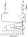
- the excitation wavelength filter is a commonly available 1 millimeter thick UG11 light filter with pass band in the range of 320-380 nanometers, as shown by curve 610 in Figure 6.
- Reference emission wavelength light filter 40 is positioned to filter the emitted emmission light filter 41 is positioned to filter the emmitted light from vial 24 that illuminates measurement sensor 38.
- Filters 40 and 41 are a combination of a commonly available 2 millimeter thick BG39 light filter as shown by curve 612 and blue colored film as shown by curve 614 providing a combination pass band in the range of 450-550 nanometers as shown by curve 616 in Figure 6.
- the combination effect of excitation filter 32 plus the effect of fluorescing filters 40 and 41 is shown by curve 618 of Figure 6 illustrating that little transmission of light from lamp 28 directly reaches reference sensor 36 or measurement sensor 38.
- Apparatus 10 is a dual channel detector which compares the results of two measurements to make a determination of pass or fail. The first measurement is based on the light output from reference material 34 as incident on reference sensor 36. The second measurement is based on light output from the test vial 24 as incident on measurement sensor 38. However, before these measurements and the resultant comparison made, apparatus 10 must be subjected to rigorous calibration to ensure proper operation and accuracy in the results.
- Fluorescent reference material 34 includes a fluorescing material that emits light at the nominal wavelength of 450 nanometers when excited by light energy of wavelength within the range of 300 to 400 nanometers.
- Test vial 24 is includes a fluorescent dye that reacts with essentially the same spectra as reference material 34 when test vial 24 is active, i.e., when the sterilization cycle is not effective.
- the fluorescing material included in reference material 34 is Barium Magnesium Aluminate Europium, available from GTE Company, dispersed approximately 2% by dry weight in a clear adhesive coated on a polyethylene substrate and in turn coated with a clear cover to maintain integrity.
- reference material 34 is positioned such that light emitted from reference material 34 passes through fluorescing filter 40 and is incident on reference sensor 36, a photodiode, producing a signal monitored by amplifier 50 and amplifier/comparator 52 producing reference signal 54.
- Reference sensor 36 is biased by resistor 55.
- Reference signal 54 is supplied to microprocessor 56 and to voltage control circuit 42.
- amplifier 50 has a gain of 6170 and amplifier/comparator 52 has a gain of 33, creating a nominal reference signal 54 voltage of 3.5 volts.
- Potentiometer 58 under control from microprocessor 56, controls the compare voltage of amplifier/comparator 52.
- test vial 24 is positioned such that emitted light from any fluorescing material contained in test vial 24 passes through fluorescing filter 41 and is incident on measurement sensor 38, a photodiode, producing a signal whose amplitude is proportional to the amount of light emission from test vial 24.
- This signal is monitored by amplifier 64 and amplifier/comparator 66 producing a target output signal which is supplied to microprocessor 56 for analysis.
- amplifier 64 has gain of 3300 and amplifier/comparator 66 has gain of 2.
- Target output signal 68 is calibrated as discussed below to a voltage of 3.8 volts, thus providing a 0.3 volt margin for a pass or no pass threshold.
- Measurement sensor 38 is biased by resistor 62. Potentiometer 70, under control from microprocessor 56, controls the compare voltage of amplifier/comparator 66.
- the gain of amplifier 50 and amplifier/comparator 52, of reference section 48 is significantly greater than the gain of amplifier 64 and amplifier/comparator 66, of measurement section 60. This makes reference section 48 significantly more sensitive than measurement section 60.
- the apparatus 10 is balanced after manufacturing. If the manufacturing jumper 86 is connected to microprocessor 56, microprocessor 56 adjusts reference potentiometer 58 to mid-range. A mechanical shutter (not shown) is then employed between reference material 34 and reference sensor 36 to adjust reference signal 54 to a predetermined operational set point, preferably 3.5 volts. Microprocessor 56 controls the operator by red light (turn screw right) or green light (turn screw left) or flashing green and red lights (finished).
- Microprocessor 56 receives digital information inputs through analog-to-digital convertor 72 from reference signal 54 and measurement signal 68 as well as a signal from start sensor 26.
- Microprocessor program memory is contained in conventional memory 74.
- Microprocessor 56 follows a program as diagrammed in Figure 5 and discussed below.
- Microprocessor controls digital potentiometer 58 and digital potentiometer 70 and supplies appropriate information to lights 18 and auditory warning device 76, a buzzer, during calibration and operation also as discussed below.
- Calibration of lamp 28 is first accomplished in reference section 48 under control of microprocessor 56 as illustrated portion 110 of Figure 5.
- lamp 28 is energized (step 200).
- Digital potentiometer 58 is set to zero (step 201) which drives the voltage to lamp 28 below predetermined operating point.
- a step counter is set to zero (step 202).
- steps 203 and 204 increase digital potentiometer 58 and increases the voltage at lamp 28 and the associated light emission until reference signal 54 reaches a predetermined level, e.g. 2.8 volts.
- lamp 28 is turned off (step 206) and the yellow light 18, a light emitting diode, is turned on (step 207) indicating that the apparatus 10 as operational.
- Reference section 48 provides a negative feedback loop so that if lamp 28 is not operational, no light impinges upon reference sensor 36 or if any of the component parts of reference section 48 malfunction, the feedback loop is interrupted and the iterative sequence continues moving potentiometer 58 to step number 100 where lamp 28 is turned off (step 208) and yellow light 18 flashes. No further steps are allowed in the sequence of operation.
- Lamp 28 is turned on (step 302), yellow light 18 is turned off (step 304), and digital potentiometer 70 is set to zero (steps 306 and 308) driving the value of measurement signal 68 to a low level, e.g., below 0.5 volts. Successive iterations (steps 310 and 312) move digital potentiometer 70 until the voltage of measurement signal 68 reaches a predetermined level. Lamp 28 is then turned off (step 314) and a green light 18 is turned on and a beeping sound is emitted from buzzer 76 indicating that apparatus 10 is ready for use (step 320).
- the predetermined value for measurement signal 68 is 3.8 volts.
- Step 316 causes The yellow light 18 is set to flash (step 318) and further steps in the sequence are blocked.
- the apparatus 10 is then ready for the operating sequence for testing the target sterilization monitoring vials as illustrated in portion 130 of Figure 5.
- a target vial is inserted as a test vial 24 into vial cavity assembly 22 and pressed down to activate start sensor 26 (step 400).
- Lamp 28 is energized to full illumination and a green light 18, which indicates ready status, is turned off (step 402).
- a series of five separate readings of the target output signal are recorded over a period of less than one second (step 406).
- the lamp 28 voltage is checked (step 410), and lamp 28 is turned off (step 414).
- Target vial measurement continues by comparing an average of the five readings plus a error threshold with the calibration voltage (step 416), as the output was inverted. If the result is greater than the calibration voltage, the green light 18 is turned on and buzzer 76 is sounded (step 420) for five seconds indicating a negative target vial, i.e., the target vial passes the sterilization test.
- the red light 18 is turned on and buzzer 76 is sounded for five seconds (step 418) indicating a positive vial and failure of the sterilization test. If the five vial measurements (step 406) are not stable, a warning is indicated with flashing red and green lights 18 (step 408) and the operating sequence is halted. In either case apparatus 10, blocks further steps in the sequence until vial 24 is removed. After removal of vial 24, the green light 18 is turned on and the apparatus 10 returned to ready status (step 422).
- step 410 If the voltage of lamp 28 is not in range (step 410), preferably the reference voltage of 3.5 volts, yellow light 18 is turned on (step 412) and the operating sequence is interrupted.
Abstract
Description
- The present invention relates generally to apparatus and methods for detecting fluorescence of a luminescent material and, more particularly, to such methods and apparatus used in sterilization monitors.
- There are many environments where the sterilization of articles is of critical importance. Hospitals and medical offices must sterilize certain equipment before that equipment can be utilized with surgical procedures or in sterile environments. Also food service environments must take care that their utensils and equipment are sterilized in order to prevent subsequent possible infection of later users.
- Commonly the equipment, instruments or materials that are to be sterilized may be subjected to the necessary parameters to achieve sterilization including the interrelated parameters of time, temperature, steam, dry heat, chemicals such as ethylene oxide gas or radiation dosage. The sterilization process is designed to kill living organisms which might otherwise contaminate the goods being sterilized. Steam sterilization ranges from 121 - 132 degrees Centigrade with exposure times of three minutes at 132 degrees Centigrade to 30 minutes at 121 degrees Centigrade. Ethylene oxide sterilization ranges from 30 to 65 degrees Centigrade with exposure times of one hour to four hours. Dry heat sterilization typically is two hours at 180 degrees Centigrade.
- Since it is critical in many environments that the sterilization be complete, frequently sterilization monitors are utilized. Typically, a small vial, or other container, is inserted into the sterilization unit in order to check upon the completeness of the sterilization process. The vial typically will contain living organisms that are provided nourishment and an environment for rapid growth after being subjected to the sterilization process.
- The vial can then be checked for growth of the organism after a incubation period. The incubation allows any organism surviving the sterilization process to grow to a detectable level. Survival of the organism indicates an inadequate sterilization process.
- In order to properly detect living organisms, typically a substrate material is added to the vial for the living organisms to react with causing the substrate to change color.
- Typically, the reading or analysis of the color change has been done manually with observation by the human eye. However, in one sterilization monitor process, a potentially luminescent substrate material is added to the vial for the living organisms to react with. After allowing for a suitable reaction period, the vial is subjected to a fluorescent light, typically an ultraviolet wavelength light, which excites the invisible to the naked eye fluorescence to appear as visible light. The appearance of visible light in the vial when subjected to an exciting fluorescent light would indicate inadequate sterilization, due at least in part to a shortened time period required for the growth of the living organisms, more automated fluorescence detectors are to be utilized.
- Further to more rapidly determine the completeness of the sterilization process, it is desired that fluorescence from the luminescent substrate in the vial be measured at a very low threshold, approximately 0.1 picowatt.
- United States Patent No. 5,073,488, Matner, Foltz and Woodson, Rapid Method For Determining Efficacy Of A Sterilization Cycle And Rapid Read-out Biological Indicator discloses a method of developing the fluorescing indicator used in a fluorescence detection apparatus.
- Unfortunately, the ultraviolet light source typically used tends to be very unstable due in part to variances in the gas ionization at one or more of the cathodes located at each end of the ultraviolet light source. Further, localized heat variations and emission fluctuations cause the output of the ultraviolet light source (lamp) to contain many independently varying harmonics of the power line frequency. The overall crest-to-trough ratio fluctuates similarly. The use of DC coupled amplifiers with low pass filtering to remove these fluctuations is unacceptable because the DC drift would be well in excess of the signal level being measured.
- Prior art fluorescence detectors sometimes utilize dual channels to attempt to adjust for these fluctuations. However, a further problem exists when dual channels are utilized or when the target measurement is taken at a different time from the reference. Since, the signal being measured is so small, minor variations in components between dual channels, even with costly matched components, and between different times of measurement can result in a complete "swamping" of the signal to be measured. The result can easily be an inaccurate measurement. In order to compensate for the inherent inaccuracies in measurement, the "growth" period must be expanded (or not reduced) in order to ensure that living organisms, if present, will be detected.
- United States Patent No. 4,626,684, Landa, discloses an apparatus for rapidly conducting fluorescence measurements. The electronics of the apparatus utilizes dual channels. One channel detects the fluorescence of the sample. The other channel detects the fluorescence of a reference. The "background" reference fluorescence is subtracted from the signal sample in order to account for the background. However, in order for the reference to be effectively canceled, the dual channels must be exactly matched.
- United States Patent No. 4,668,868, Noller, discloses a fluorescence detector for performing fluoroimmunoassays of biological specimens. The light energy from the sample is used to excite a photovoltaic cell. Temperature compensation is provided by a second photovoltaic cell from which light excitation is eliminated. A push button calibrator also used to provide a bias voltage from the voltaic cell with zero input signal which is memorized. A significant disadvantage of the system of Noller is the lack of a reference value. Since fluctuations in the intensity of stimulating radiation may greatly affect the amount of visible light output apparently perceived can vary greatly.
- United States Patent No. 5,030,297, Williams et al, Apparatus For Detecting Fluorescence Of A Luminescent Material discloses the construction and operation of an electronic instrument for go/no-go measurement of a fluorescing sterilization monitor. An electronic circuit follows the power fluctuation of the excitation light source and thus follows the variations of the light output. Calibration of this system is manual.
- United States Patent No. 5,063,297, Hardenbrook et al, Apparatus For Detecting Fluorescence Of A Luminescent Material is similar to the Williams '297 patent and discloses a single channel detector circuit.
- The present invention provides an apparatus and method for detecting fluorescence to determine the relative fluorescence of a sterilization monitor vial. The apparatus and method provides for automated calibration to insure initial calibration, stabilization and accuracy within critical limits.
- Generally, automated operation of the apparatus and method of the present consists of three phases. Each phase must be successfully executed before the next can begin.
- First, when the apparatus is energized and before it is operational, a sequence of steps sets the operating voltage level of the excitation light source and the associated reference signal level.
- Second, following this first calibration step, the operator inserts a new and unused vial selected from the current production lot being used for sterilization monitoring. The unused vial has not been subjected to an incubation and accordingly no growth of the organisms has occurred. This vial then only gives a minimal fluorescence which is subject to the calibration in this step. The apparatus then calibrates the vial measurement signal to match the reference signal. At this point the new vial is removed and the unit remains in a standby status until test (target) vials are ready for analysis.
- Third, following this second calibration step the apparatus is ready for actual vial monitoring. A test (target) vial is inserted into the apparatus. The excitation lamp is energized to full voltage, after a stabilization period, the vial light emissions are measured, compared with each other for stability, and the lamp voltage is compared with set up. If the vial measurements fall within a stable range and lamp voltage measurement is within specifications, the apparatus compares the average test vial emission with the calibration value. If the measured result is within the calibration value indicating that no active material is present in the test vial, an indicator is set. If the measured result is outside the calibration value plus a predetermined threshold value indicating that active material is still present in the vial a different indicator is set. If the various measurements are not stable, a warning signal is set.
- The present invention provides an apparatus for detecting fluorescence of an unknown target material being excitable at an excitation wavelength and fluorescing at a fluorescing wavelength. An energy source is arranged to excite both the target material and a reference material at approximately the excitation wavelength. A power supply supplies electrical power having an adjustable voltage to the energy source. An excitation filter is optically arranged between the energy source and both of the target material and the reference material, the excitation filter passing light energy at approximately the excitation wavelength. A reference detector is optically arranged to be responsive to and for detecting light emitted from the reference material at approximately the fluorescing wavelength. A target detector is optically arranged to be responsive to and for detecting light emitted from the target material at approximately the fluorescing wavelength. Reference measurement means generates a reference output in response to the reference detector means in order to determine the amount of fluorescence generated by the reference material. Target measurement means generates a target output in response to the target detector means in order to determine the amount of fluorescence generated by the target material. Reference calibration means is coupled to the reference measurement means and to the power supply means for varying the electrical voltage supplied to the energy source and for calibrating the reference output. Target calibration means is coupled to the target measurement means for calibrating the target output in response to a known target material. Thus, the apparatus may have the reference measurement means calibrated without a target material, then may have the target measurement means calibrated using the known target material, and then may have the target measurement means determine the fluorescence of the unknown target material.
- In a preferred embodiment, the reference detector is a photodiode.
- In a preferred embodiment, the apparatus has a first fluorescing wavelength filter optically arranged between the reference material and the photodiode of the reference detector means. The fluorescing first wavelength filter passes light energy at approximately the fluorescing wavelength.
- In a preferred embodiment, A second fluorescing wavelength filter is optically arranged between the target material and the photodiode of the target detector means. The second wavelength filter passes light energy at approximately the fluorescing wavelength.
- The present invention also provides a method for detecting fluorescence of an unknown target material being excitable at an excitation wavelength and fluorescing at a fluorescing wavelength in an apparatus having a reference material; an energy source arranged to excite both the target material and the reference material at approximately the excitation wavelength; power supply means for supplying electrical power having an adjustable voltage to the energy source; a reference detector means optically arranged to be responsive to the reference material at approximately the fluorescing wavelength; a target detector means optically arranged to be responsive to the target material at approximately the fluorescing wavelength; reference measurement means for generating a reference output in response to the reference detector means in order to determine the amount of fluorescence generated by the reference material; target measurement means for generating a target output in response to the target detector means in order to determine the amount of fluorescence generated by the target material. The method comprises the steps of calibrating the energy source and the reference measurement means without a target material; calibrating the target measurement means using the known target material; and measuring the unknown target material using the target measurement means to determine the fluorescence of the unknown target material.
- In a preferred embodiment, the method further comprises the steps of verifying that the energy source is operational; verifying that the reference measurement means is operational; and providing an alarm if the energy source or the reference measurement means is not operational.
- In a preferred embodiment, the method further comprises the steps of verifying that the target measurement means is operational; and providing an alarm if the energy source or the target measurement means is not operational.
- The foregoing advantages, construction and operation of the present invention will become more readily apparent from the following description and accompanying drawings in which:
- Figure 1 is an end view of an apparatus constructed in accordance with the present invention;
- Figure 2 is a simplified cross-sectional view of the apparatus of Figure 1 taken along lines I-I;
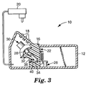
- Figure 3 is a simplified cross-sectional view of the apparatus of Figure 1 taken along lines II-II;
- Figure 4 is a circuit diagram of the apparatus of the present invention;
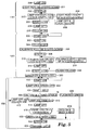
- Figure 5 is a flow diagram illustrating the sequencing of operations controlled by the microprocessor of the apparatus of the present invention;
- Figure 6 illustrates the filtering characteristics of the excitation filter of the apparatus of the present invention; and
- Figures 7a and 7b are a detailed circuit diagram of a preferred embodiment of the apparatus of the present invention.
- The preferred apparatus for detecting fluorescence is a fully automated instrument for determining of the relative fluorescence of a sterilization monitor vial. The light source for excitation of the fluorescent material is a halogen lamp held in a stable standby (warm) state, energized to full illumination only when a vial is inserted into a cavity in the instrument housing actuating a light switch. Excitation light from this halogen lamp is guided in two parallel light paths through light filters providing a selected wave length band to the vial and to a fluorescing reference film. Emitted light from the fluorescent film and the from the vial is guided onto separate detectors providing signals for evaluation by a programmed micro-processor. Results of the micro-processor program provide output information of the relative fluorescence and/or the apparatus performance. Normal output information is in the form of yes/no result signal indicated by green or red lights. It is possible to obtain specific values of light output from the vial. Further, the micro-processor provides self-calibration of the system and automatic diagnostics of performance.
- Automated operation consists of three phases controlled serially by the micro-processor. Preferably, each phase must be successfully executed before the next can begin, as follows:
First, when the apparatus is energized and before it is operational, a sequence of steps sets the operating condition of the excitation light source and the associated reference signal level. Final sequence step of this phase is to turn on the yellow LED indicating that the apparatus is operational. - Second, following this initial calibration step, a new and unused vial is selected from the current production lot being used for sterilization monitoring and is inserted into the measurement location of the apparatus. The apparatus then calibrates, preferably by a sequence of steps, the vial measurement signal to match the reference signal and, if successful, turns on the green light indicating that the apparatus is in ready status. At this point the new and unused vial is removed and the apparatus remains in a standby status until test vials are ready for analysis. During each of the first two phases a flashing yellow light is turned on if the sequence cannot be completed within predetermined limits.
- Third, the apparatus performs actual test (target) vial monitoring. A test (target) vial to be measured is inserted and the green light is turned off. The excitation lamp is energized to full voltage. After, preferably a delay period and, a stabilization period of multiple readings, preferably five, of the light emission of the test vial at the fluorescing wavelength are measured and compared to each other for stability. The lamp voltage is measured and compared with the calibrated value. If the vial measurements fall within a stable range and lamp voltage measurement is within predetermined limits, the apparatus compares the average of the target vial fluorescing wavelength light emissions with the calibrated reference value. If the result is within predetermined limits of the reference value, no active material is present within the vial. The green light, and preferably a beeper, is/are turned on indicating that the test vial is negative. If the result is outside the reference value, preferably plus a threshold value for safety, the red light and a beeper are turned on indicating a positive test indication from the target vial representing the presence of active, unsterilized material in the target vial. If the measurements are not stable, selected warning signals are turned on.
- Figures 1, 2 and 3 are drawings illustrating the
fluorescence detecting apparatus 10. Thehousing 12 is roughly three inches (7.62 centimeters) wide, six inches (15.24 centimeters) long and two inches (5.08 centimeters) high. The top surface has anopening 14 allowing entry to atest vial cavity 16, and threelights 18, preferably one each of yellow, red and green. Theapparatus 10 is powered by anexternal power supply 20 providing 15 volts for a 7.5 watt load (0.5 amperes). -
Vial cavity assembly 22 is mounted withincavity 16 ofhousing 12 and is positioned to accept avial 24.Start sensor 26 is actuated when thevial 24 is inserted intovial cavity assembly 22.Halogen lamp 28, operating as the excitation energy source, is held in socket/reflector assembly 30.Halogen lamp 28 directs excitation wavelength light through ultra-violet bandpass excitation filter 32. Afluorescent reference material 34 is positioned parallel to thevial cavity assembly 22 in the excitation light path. Areference sensor 36 and ameasurement sensor 38 are positioned parallel to each other in line withvial 24 andreference material 34, respectively. Afluorescing wavelength filter 40, passing wavelengths in the fluorescing range, is positioned betweenreference material 34 andreference sensor 36 and asimilar filter 41 betweenvial 24 andmeasurement sensor 38. - Figure 4 is an electrical circuit block diagram of the
apparatus 10 for detecting fluorescence. Halogen filledincandescent lamp 28 provides an excitation light source for theapparatus 10. Halogen filledincandescent lamp 28 is a conventional 12volt 5 watt lamp.Lamp 28 is held in a warm state emitting little or no light at a standby power of approximately 0.33 watts at all times theapparatus 10 is energized frompower supply 20. During operation,lamp 28 provides full illumination at above nominal rating, at approximately 11.8 volts providing above nominal ultraviolet energy for excitation ofreference material 34 andtest vial 24. The energization voltage tolamp 28 is regulated byvoltage control 42. Standby power is limited byresistor 44.Resistor 44 is bypassed bysolid state switch 46 during full operating condition. Holdinghalogen lamp 28 in a warm state allows light output stabilization in less than 1 second following switching to full power. This increases the operating life oflamp 28 by minimizing cold turn-ons and the associated limitation of the high power inrush immediately following turn-on. -
Excitation filter 32 is positioned to pass only excitation wavelength light emitted bylamp 28 as directed in parallel paths to referencematerial 34 andtest vial 24. The excitation wavelength filter is a commonly available 1 millimeter thick UG11 light filter with pass band in the range of 320-380 nanometers, as shown bycurve 610 in Figure 6. Reference emission wavelengthlight filter 40 is positioned to filter the emittedemmission light filter 41 is positioned to filter the emmitted light fromvial 24 that illuminatesmeasurement sensor 38.Filters curve 612 and blue colored film as shown bycurve 614 providing a combination pass band in the range of 450-550 nanometers as shown bycurve 616 in Figure 6. The combination effect ofexcitation filter 32 plus the effect offluorescing filters curve 618 of Figure 6 illustrating that little transmission of light fromlamp 28 directly reachesreference sensor 36 ormeasurement sensor 38. -
Apparatus 10 is a dual channel detector which compares the results of two measurements to make a determination of pass or fail. The first measurement is based on the light output fromreference material 34 as incident onreference sensor 36. The second measurement is based on light output from thetest vial 24 as incident onmeasurement sensor 38. However, before these measurements and the resultant comparison made,apparatus 10 must be subjected to rigorous calibration to ensure proper operation and accuracy in the results. -
Fluorescent reference material 34 includes a fluorescing material that emits light at the nominal wavelength of 450 nanometers when excited by light energy of wavelength within the range of 300 to 400 nanometers.Test vial 24 is includes a fluorescent dye that reacts with essentially the same spectra asreference material 34 whentest vial 24 is active, i.e., when the sterilization cycle is not effective. The fluorescing material included inreference material 34 is Barium Magnesium Aluminate Europium, available from GTE Company, dispersed approximately 2% by dry weight in a clear adhesive coated on a polyethylene substrate and in turn coated with a clear cover to maintain integrity. - Having reference to
reference section 48 of Figure 4,reference material 34 is positioned such that light emitted fromreference material 34 passes throughfluorescing filter 40 and is incident onreference sensor 36, a photodiode, producing a signal monitored byamplifier 50 and amplifier/comparator 52 producingreference signal 54.Reference sensor 36 is biased byresistor 55.Reference signal 54 is supplied tomicroprocessor 56 and tovoltage control circuit 42. In thepreferred reference circuit 48,amplifier 50 has a gain of 6170 and amplifier/comparator 52 has a gain of 33, creating anominal reference signal 54 voltage of 3.5 volts.Potentiometer 58, under control frommicroprocessor 56, controls the compare voltage of amplifier/comparator 52. - Having reference to
measurement section 60 of Figure 4,test vial 24 is positioned such that emitted light from any fluorescing material contained intest vial 24 passes throughfluorescing filter 41 and is incident onmeasurement sensor 38, a photodiode, producing a signal whose amplitude is proportional to the amount of light emission fromtest vial 24. This signal is monitored byamplifier 64 and amplifier/comparator 66 producing a target output signal which is supplied tomicroprocessor 56 for analysis. In thepreferred measurement section 60,amplifier 64 has gain of 3300 and amplifier/comparator 66 has gain of 2.Target output signal 68 is calibrated as discussed below to a voltage of 3.8 volts, thus providing a 0.3 volt margin for a pass or no pass threshold.Measurement sensor 38 is biased byresistor 62.Potentiometer 70, under control frommicroprocessor 56, controls the compare voltage of amplifier/comparator 66. - Note that the gain of
amplifier 50 and amplifier/comparator 52, ofreference section 48, is significantly greater than the gain ofamplifier 64 and amplifier/comparator 66, ofmeasurement section 60. This makesreference section 48 significantly more sensitive thanmeasurement section 60. Theapparatus 10 is balanced after manufacturing. If themanufacturing jumper 86 is connected tomicroprocessor 56,microprocessor 56 adjustsreference potentiometer 58 to mid-range. A mechanical shutter (not shown) is then employed betweenreference material 34 andreference sensor 36 to adjustreference signal 54 to a predetermined operational set point, preferably 3.5 volts.Microprocessor 56 controls the operator by red light (turn screw right) or green light (turn screw left) or flashing green and red lights (finished). -
Microprocessor 56 receives digital information inputs through analog-to-digital convertor 72 fromreference signal 54 andmeasurement signal 68 as well as a signal fromstart sensor 26. Microprocessor program memory is contained inconventional memory 74.Microprocessor 56 follows a program as diagrammed in Figure 5 and discussed below. Microprocessor controlsdigital potentiometer 58 anddigital potentiometer 70 and supplies appropriate information tolights 18 andauditory warning device 76, a buzzer, during calibration and operation also as discussed below. - Calibration of
lamp 28 is first accomplished inreference section 48 under control ofmicroprocessor 56 as illustratedportion 110 of Figure 5. When theapparatus 10 is energized, e.g., by plugging inpower supply 20, at the beginning of a work period,lamp 28 is energized (step 200).Digital potentiometer 58 is set to zero (step 201) which drives the voltage tolamp 28 below predetermined operating point. A step counter is set to zero (step 202). However, light continues to impingereference sensor 36 resulting in stable feedback at a low value ofreference voltage 54. Successive iterations (steps 203 and 204) increasedigital potentiometer 58 and increases the voltage atlamp 28 and the associated light emission untilreference signal 54 reaches a predetermined level, e.g. 2.8 volts. At this point,lamp 28 is turned off (step 206) and theyellow light 18, a light emitting diode, is turned on (step 207) indicating that theapparatus 10 as operational. -
Reference section 48 provides a negative feedback loop so that iflamp 28 is not operational, no light impinges uponreference sensor 36 or if any of the component parts ofreference section 48 malfunction, the feedback loop is interrupted and the iterative sequence continues movingpotentiometer 58 to stepnumber 100 wherelamp 28 is turned off (step 208) and yellow light 18 flashes. No further steps are allowed in the sequence of operation. - Provided that the steps outlined in
portion 110 of Figure 5 are accomplished successfully, automated calibration of theapparatus 10 proceeds as illustrated inportion 120 of Figure 5. Calibration of theapparatus 10 is required each time it is energized and each time a new lot of test (target) vials is used. Any new and unused test vial will have a minor background level of fluorescent light emission due to the materials and processing used in manufacture, the level of emission is stable in time but varies from lot to lot, thus for the comparative test this background emission must be calibrated out for evaluating active vials. A new andunused vial 24, from the selected manufacturing lot, intovial cavity assembly 22 and pressed down to actuate start sensor 26 (step 300).Lamp 28 is turned on (step 302),yellow light 18 is turned off (step 304), anddigital potentiometer 70 is set to zero (steps 306 and 308) driving the value ofmeasurement signal 68 to a low level, e.g., below 0.5 volts. Successive iterations (steps 310 and 312) movedigital potentiometer 70 until the voltage ofmeasurement signal 68 reaches a predetermined level.Lamp 28 is then turned off (step 314) and agreen light 18 is turned on and a beeping sound is emitted frombuzzer 76 indicating thatapparatus 10 is ready for use (step 320). In the preferred circuit arrangement, the predetermined value formeasurement signal 68 is 3.8 volts. - If any of the circuit components malfunction or if the test vial emits no light, the successive iterations of
digital potentiometer 70 will continue until a predetermined maximum of 100 steps is reached (step 316). Step 316 then causes Theyellow light 18 is set to flash (step 318) and further steps in the sequence are blocked. - The
apparatus 10 is then ready for the operating sequence for testing the target sterilization monitoring vials as illustrated inportion 130 of Figure 5. After theapparatus 10 is calibrated as described above, a target vial is inserted as atest vial 24 intovial cavity assembly 22 and pressed down to activate start sensor 26 (step 400).Lamp 28 is energized to full illumination and agreen light 18, which indicates ready status, is turned off (step 402). After a one second delay (step 404) to stabilize light output of thehalogen lamp 28, a series of five separate readings of the target output signal are recorded over a period of less than one second (step 406). If these values, when compared to each other, have less than a predetermined variance tolerance, preferably 0.1 volts, thelamp 28 voltage is checked (step 410), andlamp 28 is turned off (step 414). Target vial measurement continues by comparing an average of the five readings plus a error threshold with the calibration voltage (step 416), as the output was inverted. If the result is greater than the calibration voltage, thegreen light 18 is turned on andbuzzer 76 is sounded (step 420) for five seconds indicating a negative target vial, i.e., the target vial passes the sterilization test. However, if the result is less than the calibration voltage, thered light 18 is turned on andbuzzer 76 is sounded for five seconds (step 418) indicating a positive vial and failure of the sterilization test. If the five vial measurements (step 406) are not stable, a warning is indicated with flashing red and green lights 18 (step 408) and the operating sequence is halted. In eithercase apparatus 10, blocks further steps in the sequence untilvial 24 is removed. After removal ofvial 24, thegreen light 18 is turned on and theapparatus 10 returned to ready status (step 422). - If the voltage of
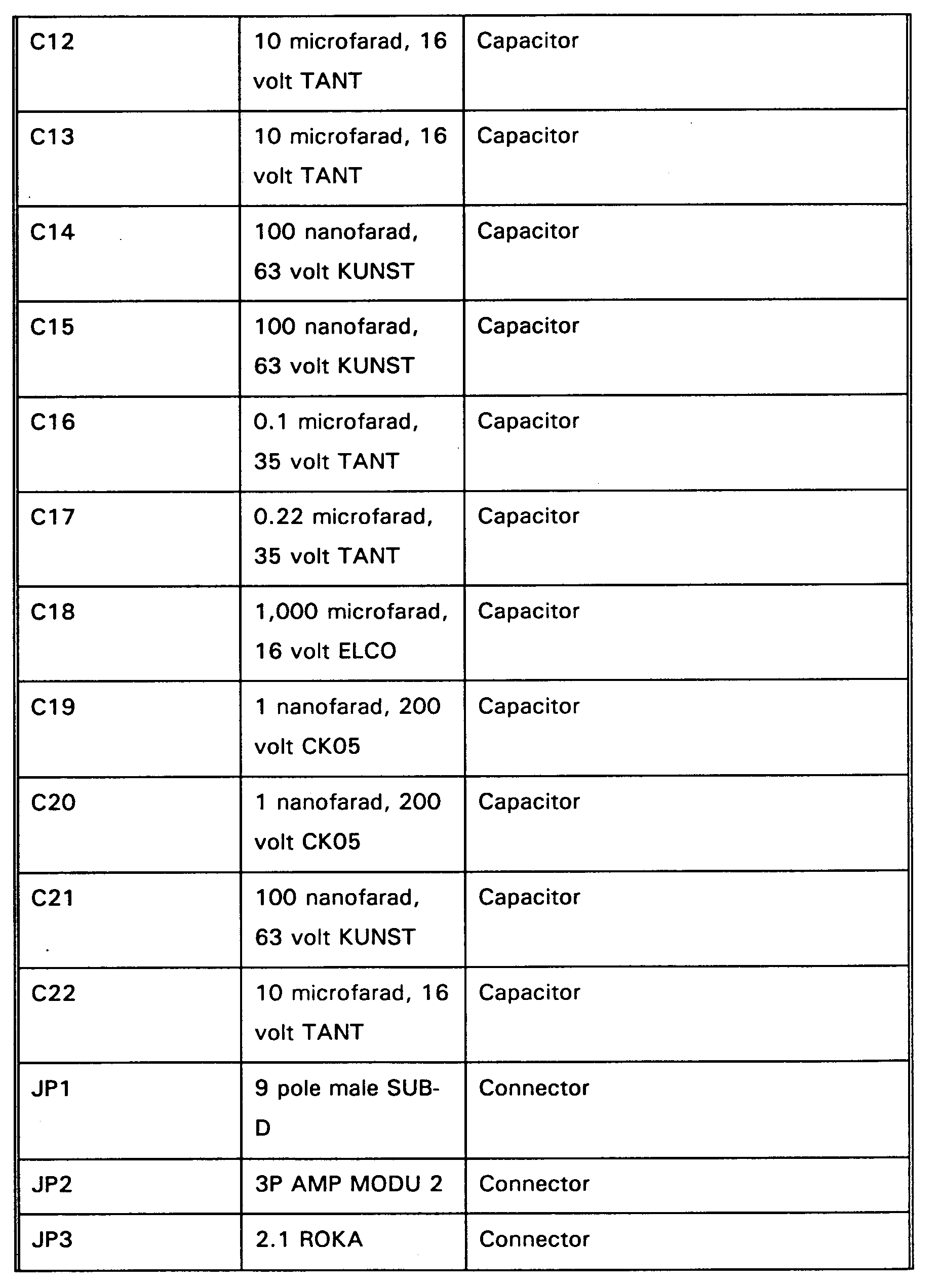
lamp 28 is not in range (step 410), preferably the reference voltage of 3.5 volts,yellow light 18 is turned on (step 412) and the operating sequence is interrupted. - A detailed circuit diagram is illustrated in Figures 7a and 7b whose component values and component identifications are contained in the following Table:


Claims (8)
- An apparatus (10) for detecting fluorescence of an unknown target material (24) being excitable at an excitation wavelength and fluorescing at a fluorescing wavelength, having a reference material (34); an energy source (28) arranged to excite both said target material (24) and said reference material (34) at approximately said excitation wavelength; power supply means (20) for supplying electrical power having an adjustable voltage to said energy source (28); an excitation filter (32) optically arranged between said energy source (28) and both of said target material (24) and said reference material (34), said excitation filter (32) passing light energy at approximately said excitation wavelength; a reference detector means (36) optically arranged to be responsive to and for detecting light emitted from said reference material (34) at approximately said fluorescing wavelength; and a target detector means (38) optically arranged to be responsive to and for detecting light emitted from said target material (24) at approximately said fluorescing wavelength; characterized by reference measurement means (48) for generating a reference output (54) in response to said reference detector means (36) in order to determine the amount of fluorescence generated by said reference material (34); target measurement means (60) for generating a target output (68) in response to said target detector means (38) in order to determine the amount of fluorescence generated by said target material (24); reference calibration means coupled to said reference measurement means (48) and to said power supply means (20) for varying the electrical voltage supplied to said energy source (28) and for calibrating said reference output (54); and target calibration means coupled to said target measurement means (60) for calibrating said target output (68) in response to a known target material.
- An apparatus (10) for detecting fluorescence as in claim 1 wherein said reference detector means (36) comprises a photodiode.
- An apparatus (10) for detecting fluorescence as in claim 2 further comprising a first fluorescing wavelength filter (40) optically arranged between said reference material (34) and said photodiode of said reference detector means (36) , said fluorescing first wavelength filter (40) passing light energy at approximately said fluorescing wavelength.
- An apparatus (10) for detecting fluorescence as in claim 3 which further comprises a second fluorescing wavelength filter (41) optically arranged between said target material (24) and said photodiode of said target detector means (38) , said second wavelength filter (41) passing light energy at approximately said fluorescing wavelength.
- An apparatus (10) for detecting fluorescence as in claim 4 in which said reference material (34) comprises a fluorescing material that emits light at the nominal wavelength of 450 nanometers when excited by light energy of wavelength within the range of 300 to 400 nanometers consisting essentially of barium magnesium aluminate europium dispersed approximately 2% by dry weight in a clear adhesive coated on a polyethylene substrate and in turn coated with a clear cover to maintain integrity.
- A method for detecting fluorescence of an unknown target material (24) being excitable at an excitation wavelength and fluorescing at a fluorescing wavelength in an apparatus having a reference material (34) ; an energy source (28) arranged to excite both said target material (24) and said reference material (34) at approximately said excitation wavelength; power supply means (20) for supplying electrical power having an adjustable voltage to said energy source (28) ; a reference detector means (36) optically arranged to be responsive to said reference material (34) at approximately said fluorescing wavelength; a target detector means (38) optically arranged to be responsive to said target material (24) at approximately said fluorescing wavelength; reference measurement means (48) for generating a reference output (54) in response to said reference detector means (36) in order to determine the amount of fluorescence generated by said reference material (34); target measurement means (60) for generating a target output (68) in response to said target detector means (38) in order to determine the amount of fluorescence generated by said target material (24), characterized by the steps of:
calibrating (110) said energy source (28) and said reference measurement means (48) without a target material (24);
calibrating (120) said target measurement means (60) using said known target material (24); and
measuring (130) said unknown target material (24) using said target measurement means (60) to determine said fluorescence of said unknown target material. - A method for detecting fluorescence as in claim 6 which further comprises the steps of:
verifying (110) that said energy source (28) is
operational;
verifying (110) that said reference measurement means (48) is operational; and
providing an alarm (208) if said energy source (28) or said reference measurement means (48) is not operational. - A method for detecting fluorescence as in claim 6 or 7 which further comprises the steps of:
verifying (130) that said target measurement means (60) is operational; and
providing an alarm (408,412,418) if said energy source (28) or said target measurement means (60) is not operational.
Applications Claiming Priority (2)
| Application Number | Priority Date | Filing Date | Title |
|---|---|---|---|
| US7758 | 1993-01-22 | ||
| US08/007,758 US5334841A (en) | 1993-01-22 | 1993-01-22 | Method and apparatus for detecting fluorescence |
Publications (2)
| Publication Number | Publication Date |
|---|---|
| EP0607941A2 true EP0607941A2 (en) | 1994-07-27 |
| EP0607941A3 EP0607941A3 (en) | 1996-03-20 |
Family
ID=21727976
Family Applications (1)
| Application Number | Title | Priority Date | Filing Date |
|---|---|---|---|
| EP94100716A Withdrawn EP0607941A3 (en) | 1993-01-22 | 1994-01-19 | Method and apparatus for detecting fluorescence in sterilization monitors. |
Country Status (4)
| Country | Link |
|---|---|
| US (1) | US5334841A (en) |
| EP (1) | EP0607941A3 (en) |
| JP (1) | JPH06258219A (en) |
| CA (1) | CA2112932A1 (en) |
Cited By (8)
| Publication number | Priority date | Publication date | Assignee | Title |
|---|---|---|---|---|
| WO1998051816A2 (en) * | 1997-05-14 | 1998-11-19 | Minnesota Mining And Manufacturing Company | System for measuring the efficacy of a sterilization cycle |
| US6025189A (en) * | 1997-05-14 | 2000-02-15 | 3M Innovative Properties Company | Apparatus for reading a plurality of biological indicators |
| US6063591A (en) * | 1997-05-14 | 2000-05-16 | 3M Innovative Properties Company | System for measuring the efficacy of a sterilization cycle |
| US6323032B1 (en) | 1996-10-07 | 2001-11-27 | 3M Innovative Properties Company | Sterilizer testing systems |
| EP2266630A1 (en) * | 2003-02-27 | 2010-12-29 | Baxter International Inc. | Device for calibration in a method for the validatable inactivation of pathogens in a biological fluid by irradiation |
| US7993580B2 (en) | 2004-08-24 | 2011-08-09 | Baxter International Inc. | Methods for the inactivation of microorganisms in biological fluids, flow through reactors and methods of controlling the light sum dose to effectively inactivate microorganisms in batch reactors |
| US8116842B2 (en) | 2004-06-10 | 2012-02-14 | Nse Products, Inc. | Bio-photonic feedback control software and database |
| US8117044B2 (en) | 2003-02-20 | 2012-02-14 | Nse Products, Inc. | Bio-photonic feedback control software and database |
Families Citing this family (16)
| Publication number | Priority date | Publication date | Assignee | Title |
|---|---|---|---|---|
| US5770393A (en) * | 1997-04-01 | 1998-06-23 | Steris Corporation | Biological indicator for detection of early metabolic activity |
| US5863790A (en) * | 1997-05-14 | 1999-01-26 | Minnesota Mining And Manfacturing Company | Biological sterility indicator |
| US6304660B1 (en) | 1998-05-29 | 2001-10-16 | Welch Allyn Data Collection, Inc. | Apparatuses for processing security documents |
| US6485979B1 (en) | 1999-08-05 | 2002-11-26 | 3M Innovative Properties Company | Electronic system for tracking and monitoring articles to be sterilized and associated method |
| US6323495B1 (en) | 1999-09-24 | 2001-11-27 | Umm Electronics, Inc. | Method and apparatus for the determination of phase delay in a lifetime fluorometer without the use of lifetime standards |
| JP4321697B2 (en) * | 2000-08-02 | 2009-08-26 | 富士フイルム株式会社 | Fluorescent image display method and apparatus |
| US7364505B2 (en) * | 2002-09-16 | 2008-04-29 | Igt | Method and apparatus for player stimulation |
| US20040197848A1 (en) * | 2003-04-01 | 2004-10-07 | Behun Bryan S. | High throughput biological indicator reader |
| US20050197581A1 (en) * | 2004-02-19 | 2005-09-08 | Scott Ferguson | Bio-photonic-scanning calibration method |
| CA2816085C (en) | 2010-11-01 | 2019-03-05 | 3M Innovative Properties Company | Biological sterilization indicator system and method |
| ES2662536T3 (en) | 2010-11-01 | 2018-04-06 | 3M Innovative Properties Company | Biological sterilization indicator system and method |
| DE102010053723A1 (en) * | 2010-11-30 | 2012-05-31 | Fraunhofer-Gesellschaft zur Förderung der angewandten Forschung e.V. | Method for non-destructive monitoring or detection of implementation of sterilization during e.g. production of prostheses, has performing comparison with reference value and/or wavelength to find whether preset energy input is carried out |
| CN104302329A (en) * | 2012-03-31 | 2015-01-21 | 学校法人早稻田大学 | Method for treating biological tissue and biological tissue |
| DE102015118175A1 (en) * | 2015-10-23 | 2017-04-27 | Marc Breit | Device for emitting electromagnetic radiation, in particular UV radiation |
| JP2016029401A (en) * | 2015-12-04 | 2016-03-03 | 東亜ディーケーケー株式会社 | Fluorometric analyzer |
| US20200256782A1 (en) * | 2017-10-09 | 2020-08-13 | Tsi Incorporated | Particle counter component calibration |
Citations (4)
| Publication number | Priority date | Publication date | Assignee | Title |
|---|---|---|---|---|
| GB2039035A (en) * | 1978-11-21 | 1980-07-30 | Medico Electronics Inc | Digital analyser |
| WO1990004775A1 (en) * | 1988-10-21 | 1990-05-03 | Biotrace Ltd. | Luminescence or fluorescence monitoring apparatus and method |
| WO1991002237A1 (en) * | 1989-08-02 | 1991-02-21 | Artel | Photometer having a long lamp life, reduced warm-up period and resonant frequency mixing |
| US5063297A (en) * | 1989-06-08 | 1991-11-05 | Minnesota Mining And Manufacturing Company | Apparatus for detecting fluorescence of a luminescent material |
Family Cites Families (7)
| Publication number | Priority date | Publication date | Assignee | Title |
|---|---|---|---|---|
| US4626684A (en) * | 1983-07-13 | 1986-12-02 | Landa Isaac J | Rapid and automatic fluorescence immunoassay analyzer for multiple micro-samples |
| US4622468A (en) * | 1985-07-15 | 1986-11-11 | Sequoia-Turner Corporation | Fluorescence intensity compensation method and device |
| US4668868A (en) * | 1986-02-20 | 1987-05-26 | Noller Hans T | Apparatus for performing fluoroimmunoassays of biological specimens |
| DE3837400C2 (en) * | 1988-11-01 | 1995-02-23 | Mannesmann Ag | Process for the production of seamless pressure vessels |
| US5073488A (en) * | 1988-11-29 | 1991-12-17 | Minnesota Mining And Manufacturing Company | Rapid method for determining efficacy of a sterilization cycle and rapid read-out biological indicator |
| US5030832A (en) * | 1989-06-08 | 1991-07-09 | Minnesota Mining And Manufacturing Company | Apparatus for detecting fluorescence of a luminescent material |
| US5032730A (en) * | 1989-10-02 | 1991-07-16 | Fuji Photo Film Co., Ltd. | Immunoassay apparatus |
-
1993
- 1993-01-22 US US08/007,758 patent/US5334841A/en not_active Expired - Lifetime
-
1994
- 1994-01-06 CA CA002112932A patent/CA2112932A1/en not_active Abandoned
- 1994-01-19 EP EP94100716A patent/EP0607941A3/en not_active Withdrawn
- 1994-01-21 JP JP6005251A patent/JPH06258219A/en active Pending
Patent Citations (4)
| Publication number | Priority date | Publication date | Assignee | Title |
|---|---|---|---|---|
| GB2039035A (en) * | 1978-11-21 | 1980-07-30 | Medico Electronics Inc | Digital analyser |
| WO1990004775A1 (en) * | 1988-10-21 | 1990-05-03 | Biotrace Ltd. | Luminescence or fluorescence monitoring apparatus and method |
| US5063297A (en) * | 1989-06-08 | 1991-11-05 | Minnesota Mining And Manufacturing Company | Apparatus for detecting fluorescence of a luminescent material |
| WO1991002237A1 (en) * | 1989-08-02 | 1991-02-21 | Artel | Photometer having a long lamp life, reduced warm-up period and resonant frequency mixing |
Cited By (12)
| Publication number | Priority date | Publication date | Assignee | Title |
|---|---|---|---|---|
| US6323032B1 (en) | 1996-10-07 | 2001-11-27 | 3M Innovative Properties Company | Sterilizer testing systems |
| WO1998051816A2 (en) * | 1997-05-14 | 1998-11-19 | Minnesota Mining And Manufacturing Company | System for measuring the efficacy of a sterilization cycle |
| WO1998051816A3 (en) * | 1997-05-14 | 1999-02-18 | Minnesota Mining & Mfg | System for measuring the efficacy of a sterilization cycle |
| US6025189A (en) * | 1997-05-14 | 2000-02-15 | 3M Innovative Properties Company | Apparatus for reading a plurality of biological indicators |
| US6063591A (en) * | 1997-05-14 | 2000-05-16 | 3M Innovative Properties Company | System for measuring the efficacy of a sterilization cycle |
| US8117044B2 (en) | 2003-02-20 | 2012-02-14 | Nse Products, Inc. | Bio-photonic feedback control software and database |
| EP2266630A1 (en) * | 2003-02-27 | 2010-12-29 | Baxter International Inc. | Device for calibration in a method for the validatable inactivation of pathogens in a biological fluid by irradiation |
| AU2009201269B2 (en) * | 2003-02-27 | 2012-02-02 | Takeda Pharmaceutical Company Limited | Method for the Validatable Inactivation of Pathogens in Biological Fluid by Irradiation |
| US8986607B2 (en) | 2003-02-27 | 2015-03-24 | Baxter International Inc. | Method for the validatable inactivation of pathogens in a biological fluid by irradiation |
| US8116842B2 (en) | 2004-06-10 | 2012-02-14 | Nse Products, Inc. | Bio-photonic feedback control software and database |
| US7993580B2 (en) | 2004-08-24 | 2011-08-09 | Baxter International Inc. | Methods for the inactivation of microorganisms in biological fluids, flow through reactors and methods of controlling the light sum dose to effectively inactivate microorganisms in batch reactors |
| US8377375B2 (en) | 2004-08-24 | 2013-02-19 | Baxter International Inc. | Methods for the inactivation of microorganisms in biological fluids, flow through reactors and methods of controlling the light sum dose to effectively inactivate microorganisms in batch reactors |
Also Published As
| Publication number | Publication date |
|---|---|
| US5334841A (en) | 1994-08-02 |
| EP0607941A3 (en) | 1996-03-20 |
| CA2112932A1 (en) | 1994-07-23 |
| JPH06258219A (en) | 1994-09-16 |
Similar Documents
| Publication | Publication Date | Title |
|---|---|---|
| EP0607941A2 (en) | Method and apparatus for detecting fluorescence in sterilization monitors | |
| EP0402030B1 (en) | Apparatus for detecting fluorescence of a luminescent material | |
| EP0454488B1 (en) | Apparatus for detecting fluorescence of a luminescent material | |
| US7206620B2 (en) | Body fluid analyte measurement | |
| US7245373B2 (en) | Spectrometer system for optical reflectance measurements | |
| EP0283289A2 (en) | Excitation and detection apparatus for remote sensor connected by optical fiber | |
| WO1997032197A1 (en) | Method and apparatus for automatic electro-optical analytical instrument for chemical assay determination | |
| US5422720A (en) | Blood culture sensor station utilizing two distinct light sources | |
| EP3513172A1 (en) | System and method for time-resolved fluoroimmunoassay detection | |
| CN105928911A (en) | Calibration method of fluorescence detection instrument | |
| US11499983B2 (en) | Automatic analysis apparatus and method for controlling automatic analysis apparatus | |
| JP2022531382A (en) | Gas sensor calibration | |
| JP2020034552A (en) | Method for correcting signal light intensities measured by detector of detection unit in device for laboratory | |
| JPH03120445A (en) | Automatic fluorescence intensity measuring instrument | |
| WO2019127548A1 (en) | Light mixing device, ultraviolet light source working indicator, and ultraviolet light source system | |
| CN205898683U (en) | Calibration device of fluorescence detector ware | |
| EP2981845A1 (en) | Apparatus and method for determining a dose of ionizing radiation | |
| EP0449992A4 (en) | Bias drift compensation in near infrared quantitative analysis instruments | |
| GB2237633A (en) | Determining the concentration of a gaseous component by fluorescence | |
| CA1183367A (en) | Optical analyzing method and system | |
| JP2000105196A (en) | Photometer | |
| CA2241246C (en) | Red blood cell spillover detection technique | |
| CN116223469A (en) | Self-adaptive phosphorescent oxygen concentration measuring device and measuring method thereof | |
| WO2001084096A1 (en) | Co2 gas measurement system for a laboratory incubator | |
| JP2001208689A (en) | Intracellular calcium concentration measuring apparatus |
Legal Events
| Date | Code | Title | Description |
|---|---|---|---|
| PUAI | Public reference made under article 153(3) epc to a published international application that has entered the european phase |
Free format text: ORIGINAL CODE: 0009012 |
|
| AK | Designated contracting states |
Kind code of ref document: A2 Designated state(s): ES FR IT |
|
| PUAL | Search report despatched |
Free format text: ORIGINAL CODE: 0009013 |
|
| AK | Designated contracting states |
Kind code of ref document: A3 Designated state(s): ES FR IT |
|
| 17P | Request for examination filed |
Effective date: 19960426 |
|
| 17Q | First examination report despatched |
Effective date: 19980820 |
|
| STAA | Information on the status of an ep patent application or granted ep patent |
Free format text: STATUS: THE APPLICATION IS DEEMED TO BE WITHDRAWN |
|
| 18D | Application deemed to be withdrawn |
Effective date: 19981231 |