EP0606961A1 - Temperature control device for reaction vessel - Google Patents
Temperature control device for reaction vessel Download PDFInfo
- Publication number
- EP0606961A1 EP0606961A1 EP94200297A EP94200297A EP0606961A1 EP 0606961 A1 EP0606961 A1 EP 0606961A1 EP 94200297 A EP94200297 A EP 94200297A EP 94200297 A EP94200297 A EP 94200297A EP 0606961 A1 EP0606961 A1 EP 0606961A1
- Authority
- EP
- European Patent Office
- Prior art keywords
- heater element
- reaction vessel
- compartment
- temperature
- cavity
- Prior art date
- Legal status (The legal status is an assumption and is not a legal conclusion. Google has not performed a legal analysis and makes no representation as to the accuracy of the status listed.)
- Granted
Links
Images


Classifications
-
- C—CHEMISTRY; METALLURGY
- C12—BIOCHEMISTRY; BEER; SPIRITS; WINE; VINEGAR; MICROBIOLOGY; ENZYMOLOGY; MUTATION OR GENETIC ENGINEERING
- C12M—APPARATUS FOR ENZYMOLOGY OR MICROBIOLOGY; APPARATUS FOR CULTURING MICROORGANISMS FOR PRODUCING BIOMASS, FOR GROWING CELLS OR FOR OBTAINING FERMENTATION OR METABOLIC PRODUCTS, i.e. BIOREACTORS OR FERMENTERS
- C12M1/00—Apparatus for enzymology or microbiology
- C12M1/02—Apparatus for enzymology or microbiology with agitation means; with heat exchange means
-
- B—PERFORMING OPERATIONS; TRANSPORTING
- B01—PHYSICAL OR CHEMICAL PROCESSES OR APPARATUS IN GENERAL
- B01L—CHEMICAL OR PHYSICAL LABORATORY APPARATUS FOR GENERAL USE
- B01L3/00—Containers or dishes for laboratory use, e.g. laboratory glassware; Droppers
- B01L3/50—Containers for the purpose of retaining a material to be analysed, e.g. test tubes
- B01L3/505—Containers for the purpose of retaining a material to be analysed, e.g. test tubes flexible containers not provided for above
-
- B—PERFORMING OPERATIONS; TRANSPORTING
- B01—PHYSICAL OR CHEMICAL PROCESSES OR APPARATUS IN GENERAL
- B01L—CHEMICAL OR PHYSICAL LABORATORY APPARATUS FOR GENERAL USE
- B01L7/00—Heating or cooling apparatus; Heat insulating devices
- B01L7/52—Heating or cooling apparatus; Heat insulating devices with provision for submitting samples to a predetermined sequence of different temperatures, e.g. for treating nucleic acid samples
-
- G—PHYSICS
- G01—MEASURING; TESTING
- G01N—INVESTIGATING OR ANALYSING MATERIALS BY DETERMINING THEIR CHEMICAL OR PHYSICAL PROPERTIES
- G01N35/00—Automatic analysis not limited to methods or materials provided for in any single one of groups G01N1/00 - G01N33/00; Handling materials therefor
-
- G—PHYSICS
- G01—MEASURING; TESTING
- G01N—INVESTIGATING OR ANALYSING MATERIALS BY DETERMINING THEIR CHEMICAL OR PHYSICAL PROPERTIES
- G01N35/00—Automatic analysis not limited to methods or materials provided for in any single one of groups G01N1/00 - G01N33/00; Handling materials therefor
- G01N35/10—Devices for transferring samples or any liquids to, in, or from, the analysis apparatus, e.g. suction devices, injection devices
- G01N35/1079—Devices for transferring samples or any liquids to, in, or from, the analysis apparatus, e.g. suction devices, injection devices with means for piercing stoppers or septums
Definitions
- the invention relates to a device for heating and cooling a reaction vessel rapidly through various temperatures, and particularly those temperatures which are used in polymerase chain reaction (PCR) amplification.
- PCR polymerase chain reaction
- PCR Polymerase chain reaction
- Technology further allows for the detection of the amplified nucleic acid material (DNA, for example) using probes which hybridize to the amplified material of choice, such probes in turn either being immobilized or immobilizable to a solid support, such as a filter membrane, and/or being labeled for detection using enzymes or other moieties.
- DNA amplified nucleic acid material
- aerosols are produced in the act of unstoppering and/or transfer of fluids.
- Such aerosols contain a few molecules of the amplified nucleic acid material, and then proceed to disperse within the environment. Normally, such few molecules in the environment are not of great concern.
- only one DNA molecule is reached to contaminate other amplifying containers yet to be used for detection. If the errant DNA molecule floats into or is inadvertently carried by an operator to another amplifying container yet to be used, that one molecule is all which will be needed to provide the DNA needed for the next amplification.
- a containment cuvette which can be a flexible pouch.
- Such pouch features wall materials which define a reaction compartment, one or both of the wall materials in the compartment being flexible.
- reaction vessel pouches have been moved through a heater and a seal-bursting station as disclosed in US-A-4066412, such technology has not been applicable to PCR since there is no provision for an active cooling cycle.
- a temperature control device for providing rapid temperature changes in a reaction vessel, the device comprising two surfaces for contacting a reaction vessel sandwiched between them, at least one of the surfaces comprising a thermally conductive material, characterized in that the control device further includes:-
- apparatus which can efficiently, inexpensively and rapidly cycle the temperature of liquid in a containment pouch from about 95°C to at least 55°C to 70°C and back to about 95°C, within ⁇ 1°C, in a time of from about 20s to 105s with a short dwell time at each of said temperatures, and without internal sensors.
- apparatus is provided to accurately produce such temperature cycling repeatedly for hundreds of times.
- the invention is described for preferred embodiments in which a PCR containment cuvette is being processed by the device, and in which both platens on opposite sides of the cuvette are heated and cooled.
- the invention is useful to heat and cool any kind of reaction vessel, whether or not used for PCR amplification, and with only one of the platens operative to effect temperature changes.
- a preferred reaction vessel operated upon by the device of the invention comprises a flexible pouch 10 formed by preferably compliant, laminated sheets 12 and 14 sealed at least around the periphery 16.
- Sheets 12 and 14 can be formed, in at least the part thereof providing a reaction compartment 20, as shown in Figure 2, of thermally conductive material 18, such as aluminium, over which a coat of a polymeric material 22 is preferably placed. This prevents the aluminium from inhibiting the amplification process.
- sheets 12 and 14 are solely comprised of a flexible plastics material. Most preferably, they comprise a sandwich of polyester and polyethylene or polypropylene, having a total thickness of between about 0.06mm and 0.2mm. Such thicknesses are useful as they ensure that the wall is sufficiently thermally conductive, even in the absence of a layer of aluminium. It is important that, whatever the materials selected, the sheets be compliant enough to conform to the surfaces pressed against the opposite sidewalls of compartment 20, shown as side walls 21 and 23 in Figure 2.
- the two sheets 12, 14 are also heat-sealed around compartment 20 at edge 24 so that a sample liquid L can be introduced by a passageway (not shown) which is then sealed and retained for processing.
- compartment 20 occurs only in sheet 12, but it can also occur in sheet 14.
- a weakened heat seal is provided between the two sheets 12 and 14 to create a future flow passageway 30 which delivers liquid to a detection compartment 32 containing suitably introduced detection reagents, and then to a waste compartment 34.
- a storage compartment can also be provided (not shown) similar to compartment 20 but containing liquid reagents.
- Dotted line A-A represents the path in cuvette 10 over which pressure means are to travel after suitable heating and cooling of compartment 20. The pressure means compresses at least compartment 20 to force liquid to flow out into compartment 32.
- the device 40 of the invention which preferably does the temperature processing of compartment 20 is shown in Figures 3 and 4. It comprises preferably a stationary support 41 and an upper member 43 which moves over the support 41. Alternatively, support 41 can be moved under member 43.
- device 40 comprises two opposed platens 42, 44, as shown in Figure 4, which have surfaces 46 to contact the cuvette, generally with the same area (here, circular) as the periphery of the compartment to be heated. Platens 42 and 44 are preferably thermally conductive material, such as aluminium. They can be grooved to allow trapped air to escape.
- Platens 42 and 44 are preferably mounted in respective housings 48, 49.
- Housing 48 is mounted in support 41 and has its outer corners beveled at 50, for reasons which will become apparent.
- Housing 48 preferably comprises a material which is poorly conducting.
- At least one of the two portions 41 and 43 has heating means and preferably means for actively cooling the heating means.
- Heating means preferably means for actively cooling the heating means.
- Active is used herein to distinguish from passive cooling which always occurs when a heating force, e.g. electricity, is removed.
- a heating element 54 is disposed (not shown for platen 42 for clarity.)
- Such a heating element is preferably a flexible, electrically driven device, such as a flexible printed circuit manufactured by Ocean State Thermotics, which can be operated at 24V D.C., to generate 20W of heat.
- a conventional temperature sensor is preferably included (not shown), on surface 46 of platen 42 and/or 44.
- Useful sensors include thermocouple and resistive temperature device (RTD) types.
- each platen 42, 44 has a wall surface 56 spaced away from the platen itself 42, 44 and its heating element 54. This space defines a gas flow cavity 58.
- wall surface 56 is then provided with preferably at least one jet inlet aperture 60, and at least one exhaust aperture 62.
- inlet aperture 60 is disposed directly opposite to, and aimed at, heating element 54.
- the exhaust aperture(s) 62 are preferably several in number and are disposed around the circumference of each platen 42, 44.
- a gas hose 64 is fluidly connected to inlet aperture 60, whereas the exhaust apertures 62 deliver the gas from cavity 58 to the atmosphere.
- hose 64 delivers air (or an inert gas) at a pressure of between about 0.98 to about 34.32kPa (about 0.01 and about 0.35 kgf/cm2).
- air or an inert gas
- Such active cooling provides the rapid decrease in temperature which is desired in reactions such as PCR amplification.
- Housing 48 is mounted on a spindle 70, to allow relative movement of the platens 42, 44 towards and away from each other. Since platen 44 and housing 49 are preferably fixed, this requires spindle 70 to be movable away from and towards cuvette 10 which is disposed on platen 44. Preferably this is achieved by mounting spindle 70 in a sliding fit in bushing 72 mounted in a frame 74. Spindle 70 can then be raised and lowered by hand or by automatic means. Alternatively, spindle 70 and platen 42 can be allowed to simply ride over the exterior surface of cuvette 10. Beveled corners 50 thus act to cam platen 42 upward when housing 48 encounters another protruding compartment.
- frame 74 is a C-shaped yoke mounted to ride on an axle 76, as shown in Figures 3 and 4.
- the yoke carries a pressure roller 78 journalled to axle 76.
- Axle 76 can then be caused to traverse cuvette 10 so that roller 78 follows path A-A, as shown in Figure 3, albeit in a non-continuous motion which allows platens 42, 44 to repeatedly heat and cool each compartment prior to rupture caused by roller 78.
- the traversal movement of axle 76 is either directed manually or by automated means (not shown).
- force F of about 9.8 to 68.6N/cm (1 to 7 kgf/cm) of roller length is preferably applied to axle 76, as shown in Figure 4, for a roller which is about 4cm long.
- a conventional microprocessor is preferably used (not shown) to control the cycling of heating element 54 and the cooling hose 64.
- the apparatus and the temperature control device are used to rapidly heat a selected portion of the reaction vessel, e.g. a containment compartment which is a reaction compartment, to the necessary high temperature, followed by a rapid cooling to a much lower temperature, achieved by the active cooling means. This is done repeatedly for as many cycles as is necessary for the desired reaction, while upper platen 42 stays in contact with the compartment.
- preferred cycling includes up to 50 repetitions, for example.
- the temperature control device 40 When the cycling is finished, the temperature control device 40 is moved out of its contact with the compartment, along path A-A and relative to the reaction vessel, by rolling the roller 78. Preferably, the roller 78 then advances into contact with the compartment in which the reaction took place to burst it and to send the contents therein to the next part of the vessel. Following this, device 40 continues on to other liquid-containing compartments in path A-A (not shown in Figure 1). For at least some of the other compartments, repeated temperature cycling is not needed, in each case, so that little or no dwell time is spent by the heating platen over such compartments, and indeed the heater element is turned off. The roller, however, is effective to burst them to push the contents to, e.g. the detection chamber.
- a temperature response curve was obtained as is shown in Figure 5.
- the compartment 20 was defined by polyester sheets 12 and 14 having a thickness of 63.5microns (2.5mil).
- the volume of the compartment was 140 ⁇ l, and it was 2.16mm thick.
- the contents was mineral oil (for purposes of measuring temperature), and a thermocouple was inserted into the oil between sheets 12 and 14.
- Trace 100 is the temperature which was delivered by platen 44, as measured by a temperature probe.
- Trace 102 is that of platen 42 itself, and trace 104 is that of the oil inside compartment 20.
- Trace 104 shows a remarkable correlation and tracking for the temperature inside the compartment, compared to that of the platen 42, even through the drastic heating and cooling which occurs between about 57°C about 97°C, and back again, all within the cycle time span of about 78s (1.3min) for the selected dwell times. (The temperature plateaus selected in this run correspond to desired temperatures for PCR amplification, as is well-known.) Faster cycling times have also been achieved - as fast as 45s.
- jet inlet aperture used to cool off the heating element can be a single aperture. Instead, it can be a plurality of apertures as shown in Figure 6. Parts similar to those previously described bear the same reference numeral to which the distinguishing suffix "A" has been appended.
- the upper portion of device 40A (only part shown) has a platen 42A in housing 48A with a heating element 54A on surface 52A as described before.
- Spindle 70A provides air to chamber 58A, and exhaust apertures 62A remove the air.
- the upper heating and cooling means is applied with a certain force against the compliant pouch to enhance contact and thus the heat conductivity. This in turn enhances the speed of the reactions therein, as shown in Figure 7.
- device 40B preferably comprises a stationary support (not shown) and an upper, movable member 43B, constrained to follow path A-A over a pouch or flexible reaction vessel 10B. Both support and member 43B are generally constructed as described above.
- upper member 43B includes means 110 for applying a specific loading force against heater platen in housing 48B.
- this force applying means 110 can be an additional selected mass mounted on the spindle to which hose 64B is connected, or even in the form of hydraulic means which bias yoke 74B to move downwardly relative to axle 76B with a predetermined force.
- a piston 120 on frame 121 can be used to apply a variable, pre-selected pressure P as shown in Figure 8.
- the amount of loading force needed for optimum compliance of the compartment side wall with the surface of the heating and cooling element depends on the materials, the material thickness, and content of the compartment. The more flexible, thinner, and compliant each side wall is, the less is the force which is required.
- the side walls and the loading force are selected to produce at least as much compliance of the side walls to the contacting surfaces, as occurs when about 2.6N (270gf or about 0.61bf) of loading force is applied by means 110 to the upper heating and cooling element 43, in contact with a compartment containing 170ml of liquid and comprising two opposed compliant sheets each consisting essentially of a sandwich of about 0.013mm thick polyester and about 0.1mm thick polyethylene. This construction provides a surface area of contact which is about 180mm2.
- each of the examples shown in Figure 10 used a single compartment of the pouch comprising two sheets each consisting essentially of a sandwich of about 0.013mm thick polyester and about 0.1mm thick polyethylene, sealed to provide a confined volume which was substantially filled with about 170ml of water, and then cycled on both sides with device 40B of Figure 7, to achieve the temperatures noted in Figure 10.
- the pressure applied by means 110 was varied to be the predetermined amount noted for each curve trace. Temperature was sensed inside the compartment. It was not until the force was at least about 2.6N (270gf) (the curve on the right-hand side of the group), for this compliant compartment, that the extreme temperatures of the cycle could be predictably achieved.
- the force applied by means 110 and the compliability of the side walls is at least that achieved by applying at least 8.8N (900gf) of force to the compartment described.
- This extra force causes the temperature of the contents to track even faster, as is evident from Figure 11, wherein the "flat" or double-peaked portions of the curve tops and valleys at 8.8N (900gf) or higher, indicate the desired end temperature is reached sooner.
- the same procedure was followed as for Figure 10, except that the force exerted by the upper heating and cooling means was one of those noted in Figure 11.
- the "flat" portion occurs because both the heating means and the cooling means are preferably programmed to provide a flat constant temperature for a few seconds, for example, for about 1s, at the extremes of the cycled temperatures.
- upper limit on the amount of force applied by upper member 43, 43A or 43B is determined primarily by the amount of force effective to burst the reaction compartment.
- the force applied by member 43 is selected to be slightly less than this value, and the force applied by the following roller is slightly greater.
- the burst force of compartment 20, as shown in Figure 1, can be, e.g. about 17.6N (1800gf).
- roller 78B can be omitted and instead piston 120 can be used to increase the pressure onto chamber 20B until it bursts, for example, at 17.6N (1800gf) of force to cause liquid to flow into the exit passageway (not shown).
Abstract
Description
- The invention relates to a device for heating and cooling a reaction vessel rapidly through various temperatures, and particularly those temperatures which are used in polymerase chain reaction (PCR) amplification.
- Polymerase chain reaction (PCR) technology permits nucleic acid material, such as DNA, often extracted from as little as a single cell, to be amplified to hundreds of millions of copies. This is important since prior to PCR technology it was virtually impossible to detect a single DNA strand. However, when a single DNA strand, such as the DNA produced by a human immunodeficiency virus (e.g. HIV-I, otherwise known to cause AIDS), is added to amplifying reagents which will amplify the DNA of choice, hundreds of millions of copies of that DNA can be obtained in a relatively short time. Technology further allows for the detection of the amplified nucleic acid material (DNA, for example) using probes which hybridize to the amplified material of choice, such probes in turn either being immobilized or immobilizable to a solid support, such as a filter membrane, and/or being labeled for detection using enzymes or other moieties.
- Conventionally, this has been done by amplifying the nucleic acid material in a stoppered plastic container until the desired number of copies have been formed. Thereafter, the container is reopened, such as by unstoppering, and either the amplified copies are withdrawn and transferred to detection apparatus, or detecting reagents are added to the container used for the amplification so that detection is done in the same container.
- It has been discovered that such a technique is unsatisfactory for convenient and widespread use of PCR technology, because aerosols are produced in the act of unstoppering and/or transfer of fluids. Such aerosols contain a few molecules of the amplified nucleic acid material, and then proceed to disperse within the environment. Normally, such few molecules in the environment are not of great concern. However, in theory, only one DNA molecule is reached to contaminate other amplifying containers yet to be used for detection. If the errant DNA molecule floats into or is inadvertently carried by an operator to another amplifying container yet to be used, that one molecule is all which will be needed to provide the DNA needed for the next amplification. Needless to say, if the point of the next test is to see if a particular DNA is present (e.g. from HIV-I), and it is detected only because of the errant DNA and not that of the patient, the test is ruined. Thus, the very power of DNA amplification becomes the source of potential ruin of the tests. As a matter of fact, an entire lab has been proven to be contaminated by the unstoppering of just a few containers in which the sample has already been amplified. Although such a problem might be avoidable by using highly skilled and trained personnel who painstakingly minimize the aerosols produced, the need for such labor makes the technology impractical for general use.
- The aforesaid problem has been solved by a containment cuvette, which can be a flexible pouch. Such pouch features wall materials which define a reaction compartment, one or both of the wall materials in the compartment being flexible.
- Although such a pouch can be heated and cooled rapidly by a variety of devices through the numerous temperature changes known in the art to be needed to do PCR amplification, there has been a need prior to this invention for simple, inexpensive and yet efficient temperature control devices especially adapted to such rapid temperature changes. It has been found, for example, that thermal cycling by heating and cooling a metal block on which a pouch sits, is relatively slow and inefficient.
- Although reaction vessel pouches have been moved through a heater and a seal-bursting station as disclosed in US-A-4066412, such technology has not been applicable to PCR since there is no provision for an active cooling cycle.
- It is therefore an object of the present invention to provide a temperature control device which produces the efficient temperature changes needed for a PCR cuvette as noted above.
- More specifically, according to one aspect of the present invention, there is provided a temperature control device for providing rapid temperature changes in a reaction vessel, the device comprising two surfaces for contacting a reaction vessel sandwiched between them, at least one of the surfaces comprising a thermally conductive material,
characterized in that the control device further includes:- - a) a heater element disposed on one side of the at least one surface;
- b) a wall surface spaced from the surface to define a cavity for providing air flow over the heater element; and
- c) cooling means in the wall surface for delivering cooling air to the cavity and the heating element, and for removing air from the cavity which has flowed over the heating element.
- It is an advantageous feature of the invention that apparatus is provided which can efficiently, inexpensively and rapidly cycle the temperature of liquid in a containment pouch from about 95°C to at least 55°C to 70°C and back to about 95°C, within ± 1°C, in a time of from about 20s to 105s with a short dwell time at each of said temperatures, and without internal sensors.
- It is a further advantageous feature of the invention that apparatus is provided to accurately produce such temperature cycling repeatedly for hundreds of times.
- Other advantageous features of the invention are that it is small in size and has low power requirements.
- The present invention will now be described by way of example only with reference to the accompanying drawings in which:
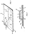
- Figure 1 is a perspective view of a simplified containment cuvette which can be processed by the device according to the present invention;
- Figure 2 is a fragmentary sectioned view taken generally along the line II--II of Figure 1;
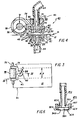
- Figure 3 is a fragmentary plan view illustrating a temperature control device constructed in accordance with the present invention, with a cuvette of Figure 1 in place;
- Figure 4 is a sectioned view taken generally along the line IV--IV of Figure 3;
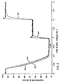
- Figure 5 is a graph of time and temperature produced by the device and cuvette of Figure 3;
- Figure 6 is a fragmentary view similar to that shown in a portion of Figure 4, but illustrating an alternative embodiment;
- Figure 7 is a plan view similar to that shown in Figure 3, but illustrating still another alternate embodiment.
- Figure 8 is a partially sectioned view similar to that shown in Figure 4 but of an alternate embodiment;
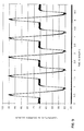
- Figure 9 is a plot of temperature and time achieved by the combination of this invention, for six different compartments processed as described, the traces showing the reproducibility of thermal cycles of the apparatus; and
- Figures 10 and 11 are each a plot of temperature vs. time similar to the plot shown in Figure 9, except that each curve represents a different level of force exerted against the compliant compartment.
- The invention is described for preferred embodiments in which a PCR containment cuvette is being processed by the device, and in which both platens on opposite sides of the cuvette are heated and cooled. In addition, the invention is useful to heat and cool any kind of reaction vessel, whether or not used for PCR amplification, and with only one of the platens operative to effect temperature changes.
- Referring first to Figures 1 and 2, a preferred reaction vessel operated upon by the device of the invention comprises a
flexible pouch 10 formed by preferably compliant, laminatedsheets 12 and 14 sealed at least around theperiphery 16.Sheets 12 and 14 can be formed, in at least the part thereof providing areaction compartment 20, as shown in Figure 2, of thermallyconductive material 18, such as aluminium, over which a coat of apolymeric material 22 is preferably placed. This prevents the aluminium from inhibiting the amplification process. - Preferably, however,
sheets 12 and 14 are solely comprised of a flexible plastics material. Most preferably, they comprise a sandwich of polyester and polyethylene or polypropylene, having a total thickness of between about 0.06mm and 0.2mm. Such thicknesses are useful as they ensure that the wall is sufficiently thermally conductive, even in the absence of a layer of aluminium. It is important that, whatever the materials selected, the sheets be compliant enough to conform to the surfaces pressed against the opposite sidewalls ofcompartment 20, shown asside walls sheets 12, 14 are also heat-sealed aroundcompartment 20 atedge 24 so that a sample liquid L can be introduced by a passageway (not shown) which is then sealed and retained for processing. As shown, the protrusion ofcompartment 20 occurs only insheet 12, but it can also occur in sheet 14. To provide selective bursting, a weakened heat seal is provided between the twosheets 12 and 14 to create afuture flow passageway 30 which delivers liquid to adetection compartment 32 containing suitably introduced detection reagents, and then to a waste compartment 34. (A storage compartment can also be provided (not shown) similar tocompartment 20 but containing liquid reagents.) Dotted line A-A represents the path incuvette 10 over which pressure means are to travel after suitable heating and cooling ofcompartment 20. The pressure means compresses at leastcompartment 20 to force liquid to flow out intocompartment 32. - The
device 40 of the invention which preferably does the temperature processing ofcompartment 20 is shown in Figures 3 and 4. It comprises preferably a stationary support 41 and anupper member 43 which moves over the support 41. Alternatively, support 41 can be moved undermember 43. Thus,device 40 comprises two opposed platens 42, 44, as shown in Figure 4, which havesurfaces 46 to contact the cuvette, generally with the same area (here, circular) as the periphery of the compartment to be heated. Platens 42 and 44 are preferably thermally conductive material, such as aluminium. They can be grooved to allow trapped air to escape. - Platens 42 and 44 are preferably mounted in
respective housings Housing 48 is mounted in support 41 and has its outer corners beveled at 50, for reasons which will become apparent.Housing 48 preferably comprises a material which is poorly conducting. - At least one of the two
portions 41 and 43 has heating means and preferably means for actively cooling the heating means. ("Active" is used herein to distinguish from passive cooling which always occurs when a heating force, e.g. electricity, is removed.) Thus, onside 52 of platens 42 and 44 which is opposite toside 46, aheating element 54 is disposed (not shown for platen 42 for clarity.) Such a heating element is preferably a flexible, electrically driven device, such as a flexible printed circuit manufactured by Ocean State Thermotics, which can be operated at 24V D.C., to generate 20W of heat. - A conventional temperature sensor is preferably included (not shown), on
surface 46 of platen 42 and/or 44. Useful sensors include thermocouple and resistive temperature device (RTD) types. - The housing for each platen 42, 44 has a
wall surface 56 spaced away from the platen itself 42, 44 and itsheating element 54. This space defines agas flow cavity 58. In order to actively cool theheating element 54,wall surface 56 is then provided with preferably at least onejet inlet aperture 60, and at least oneexhaust aperture 62. Preferably,inlet aperture 60 is disposed directly opposite to, and aimed at,heating element 54. The exhaust aperture(s) 62 are preferably several in number and are disposed around the circumference of each platen 42, 44. Agas hose 64 is fluidly connected toinlet aperture 60, whereas theexhaust apertures 62 deliver the gas fromcavity 58 to the atmosphere. Preferably,hose 64 delivers air (or an inert gas) at a pressure of between about 0.98 to about 34.32kPa (about 0.01 and about 0.35 kgf/cm²). Such active cooling provides the rapid decrease in temperature which is desired in reactions such as PCR amplification. -
Housing 48 is mounted on aspindle 70, to allow relative movement of the platens 42, 44 towards and away from each other. Since platen 44 andhousing 49 are preferably fixed, this requiresspindle 70 to be movable away from and towardscuvette 10 which is disposed on platen 44. Preferably this is achieved by mountingspindle 70 in a sliding fit inbushing 72 mounted in aframe 74.Spindle 70 can then be raised and lowered by hand or by automatic means. Alternatively,spindle 70 and platen 42 can be allowed to simply ride over the exterior surface ofcuvette 10.Beveled corners 50 thus act to cam platen 42 upward whenhousing 48 encounters another protruding compartment. - Most preferably,
frame 74 is a C-shaped yoke mounted to ride on anaxle 76, as shown in Figures 3 and 4. The yoke carries apressure roller 78 journalled toaxle 76.Axle 76 can then be caused to traversecuvette 10 so thatroller 78 follows path A-A, as shown in Figure 3, albeit in a non-continuous motion which allows platens 42, 44 to repeatedly heat and cool each compartment prior to rupture caused byroller 78. The traversal movement ofaxle 76 is either directed manually or by automated means (not shown). - When compartments such as
compartment 20 are to be compressed byroller 78 to force the liquid out into the other passageways, force F of about 9.8 to 68.6N/cm (1 to 7 kgf/cm) of roller length is preferably applied toaxle 76, as shown in Figure 4, for a roller which is about 4cm long. - A conventional microprocessor is preferably used (not shown) to control the cycling of
heating element 54 and the coolinghose 64. - When in use, the apparatus and the temperature control device are used to rapidly heat a selected portion of the reaction vessel, e.g. a containment compartment which is a reaction compartment, to the necessary high temperature, followed by a rapid cooling to a much lower temperature, achieved by the active cooling means. This is done repeatedly for as many cycles as is necessary for the desired reaction, while upper platen 42 stays in contact with the compartment. In the case of DNA replication by PCR technology, preferred cycling includes up to 50 repetitions, for example.
- When the cycling is finished, the
temperature control device 40 is moved out of its contact with the compartment, along path A-A and relative to the reaction vessel, by rolling theroller 78. Preferably, theroller 78 then advances into contact with the compartment in which the reaction took place to burst it and to send the contents therein to the next part of the vessel. Following this,device 40 continues on to other liquid-containing compartments in path A-A (not shown in Figure 1). For at least some of the other compartments, repeated temperature cycling is not needed, in each case, so that little or no dwell time is spent by the heating platen over such compartments, and indeed the heater element is turned off. The roller, however, is effective to burst them to push the contents to, e.g. the detection chamber. - More specifically, using the device of this invention, a temperature response curve was obtained as is shown in Figure 5. In this case, the
compartment 20 was defined bypolyester sheets 12 and 14 having a thickness of 63.5microns (2.5mil). The volume of the compartment was 140µℓ, and it was 2.16mm thick. The contents was mineral oil (for purposes of measuring temperature), and a thermocouple was inserted into the oil betweensheets 12 and 14. -
Trace 100 is the temperature which was delivered by platen 44, as measured by a temperature probe.Trace 102 is that of platen 42 itself, and trace 104 is that of the oil insidecompartment 20.Trace 104 shows a remarkable correlation and tracking for the temperature inside the compartment, compared to that of the platen 42, even through the drastic heating and cooling which occurs between about 57°C about 97°C, and back again, all within the cycle time span of about 78s (1.3min) for the selected dwell times. (The temperature plateaus selected in this run correspond to desired temperatures for PCR amplification, as is well-known.) Faster cycling times have also been achieved - as fast as 45s. - It is not essential that the jet inlet aperture used to cool off the heating element be a single aperture. Instead, it can be a plurality of apertures as shown in Figure 6. Parts similar to those previously described bear the same reference numeral to which the distinguishing suffix "A" has been appended.
- Thus, the upper portion of
device 40A (only part shown) has aplaten 42A inhousing 48A with aheating element 54A onsurface 52A as described before. Spindle 70A provides air tochamber 58A, and exhaust apertures 62A remove the air. However, in this case there is a plurality ofjet inlet apertures 60A, all insurface 56A which is spaced away fromheating element 54A. - Most preferably, the upper heating and cooling means is applied with a certain force against the compliant pouch to enhance contact and thus the heat conductivity. This in turn enhances the speed of the reactions therein, as shown in Figure 7. Parts similar to those previously described bear the same reference numeral, to which a distinguishing suffix "B" is applied. Thus, in Figure 7,
device 40B preferably comprises a stationary support (not shown) and an upper,movable member 43B, constrained to follow path A-A over a pouch or flexible reaction vessel 10B. Both support andmember 43B are generally constructed as described above. In addition, however,upper member 43B includesmeans 110 for applying a specific loading force against heater platen inhousing 48B. As shown, such means is a torsion spring mounted onaxle 76B, with a spring constant selected to ensure the application of the desired force, as will be described in detail later. Alternatively, this force applying means 110 can be an additional selected mass mounted on the spindle to whichhose 64B is connected, or even in the form of hydraulic means which biasyoke 74B to move downwardly relative toaxle 76B with a predetermined force. For example, apiston 120 onframe 121 can be used to apply a variable, pre-selected pressure P as shown in Figure 8. - The amount of loading force needed for optimum compliance of the compartment side wall with the surface of the heating and cooling element, depends on the materials, the material thickness, and content of the compartment. The more flexible, thinner, and compliant each side wall is, the less is the force which is required. Preferably, the side walls and the loading force are selected to produce at least as much compliance of the side walls to the contacting surfaces, as occurs when about 2.6N (270gf or about 0.61bf) of loading force is applied by
means 110 to the upper heating andcooling element 43, in contact with a compartment containing 170ml of liquid and comprising two opposed compliant sheets each consisting essentially of a sandwich of about 0.013mm thick polyester and about 0.1mm thick polyethylene. This construction provides a surface area of contact which is about 180mm². - Such compliance and the means which achieve it, have been found to produce extraordinary PCR reactions. Importantly, the contents of the heated and cooled compartment are constrained to better follow the temperature of the heating and cooling means in a repeatable fashion. This is essential since each thermal cycle must be exact in its limits to achieve DNA replication. The reproducibility of the cycles is demonstrated in Figure 9, wherein each curve represents a different compartment in six different reaction vessels, separately sequenced through the apparatus for at least five cycles using 2.2N (227gf) of force. In each case, the contents' temperature was measured by an inserted temperature probe, and the volume of each compartment was 170 to 190µℓ respectively. The result is that each compartment in each cycle reached a high temperature of at least about 93°C and a low temperature of at least about 50°C, the ranges preferred for PCR processing.
- The difficulty of operating at forces less than 2.6N (270gf) can be seen from Figure 10. For these results, each of the examples shown in Figure 10 used a single compartment of the pouch comprising two sheets each consisting essentially of a sandwich of about 0.013mm thick polyester and about 0.1mm thick polyethylene, sealed to provide a confined volume which was substantially filled with about 170ml of water, and then cycled on both sides with
device 40B of Figure 7, to achieve the temperatures noted in Figure 10. The pressure applied bymeans 110 was varied to be the predetermined amount noted for each curve trace. Temperature was sensed inside the compartment. It was not until the force was at least about 2.6N (270gf) (the curve on the right-hand side of the group), for this compliant compartment, that the extreme temperatures of the cycle could be predictably achieved. - Most preferably, the force applied by
means 110 and the compliability of the side walls is at least that achieved by applying at least 8.8N (900gf) of force to the compartment described. This extra force causes the temperature of the contents to track even faster, as is evident from Figure 11, wherein the "flat" or double-peaked portions of the curve tops and valleys at 8.8N (900gf) or higher, indicate the desired end temperature is reached sooner. In these examples, the same procedure was followed as for Figure 10, except that the force exerted by the upper heating and cooling means was one of those noted in Figure 11. The "flat" portion occurs because both the heating means and the cooling means are preferably programmed to provide a flat constant temperature for a few seconds, for example, for about 1s, at the extremes of the cycled temperatures. This ensures that the liquid temperature predictably and repeatedly reaches the needed value. Only those compartments which reach these values in a timely fashion will demonstrate the constancy of that end point temperature. Apparatus and pouches processed in this manner are better able to control the PCR amplications. - It will be apparent that the upper limit on the amount of force applied by
upper member member 43 is selected to be slightly less than this value, and the force applied by the following roller is slightly greater. The burst force ofcompartment 20, as shown in Figure 1, can be, e.g. about 17.6N (1800gf). - Some of the curves of Figure 11 show a double peak at the curve tops. This occurs only because the heating element was programmed to overshoot the desired temperature - an unnecessary step when results such as those for the curves at 8.8N (900gf) or higher force, are achieved.
- The previously-described embodiments feature the preferred use of the roller as the means for compressing and bursting the liquid-containing chambers. Any other mechanism can be used as well. For example, in Figure 8,
roller 78B can be omitted and insteadpiston 120 can be used to increase the pressure onto chamber 20B until it bursts, for example, at 17.6N (1800gf) of force to cause liquid to flow into the exit passageway (not shown).
Claims (5)
- A temperature control device for providing rapid temperature changes in a reaction vessel (10), the device comprising two surfaces (46) for contacting a reaction vessel (10) sandwiched between them, at least one of the surfaces (46) comprising a thermally conductive material,
characterized in that the control device further includes:-a) a heater element (54; 54A) disposed on one side of the at least one surface (42, 44);b) a wall surface (56; 56A) spaced from the surface (46) to define a cavity (58; 58B) for providing air flow over the heater element (54; 54A); andc) cooling means (60, 62, 64; 60A, 62A) in the wall surface (56; 56A) for delivering cooling air to the cavity (58; 58B) and the heating element (54; 54A), and for removing air from the cavity (58; 58B) which has flowed over the heating element (54; 54A). - A device according to claim 1, wherein both of the surfaces (46) comprise the thermally conductive material, and each surface (46) has an associated heater element (54; 54A), wall surface (56; 56A) and the cooling means (60, 62, 64; 60A, 62A).
- A device according to claim 1 or 2, wherein the cooling means (60, 62, 64; 60A, 62A) comprise at least one jet aperture (60; 60A) in the wall surface (56; 56A) opposite to the heater element (54; 54A), and at least one exhaust aperture (62; 62A) disposed to one side of the heater element (54; 54A), the jet aperture (60; 60A) being fluidly connected to an air source (64) and the exhaust aperture (62; 62A) being fluidly connected to the atmosphere.
- A device according to any one of claims 1 to 3, wherein at least one of the surfaces (46) is mounted on a movable frame (74; 74B), and means are provided for moving the frame (74; 74B) across a reaction vessel (10) disposed between the surfaces (42, 44).
- A device according to claim 4, further including a roller (78; 78B) mounted on the frame (74; 74B) and operable for compressing a reaction vessel (10) against the other of the surfaces not mounted on the frame (74; 74B).
Applications Claiming Priority (5)
| Application Number | Priority Date | Filing Date | Title |
|---|---|---|---|
| US36507989A | 1989-06-12 | 1989-06-12 | |
| US365079 | 1989-06-12 | ||
| US07/452,932 US5460780A (en) | 1989-06-12 | 1989-12-18 | Temperature control device and reaction vessel |
| US452932 | 1989-12-18 | ||
| EP90201464A EP0402995B1 (en) | 1989-06-12 | 1990-06-07 | Temperature control device and reaction vessel |
Related Parent Applications (2)
| Application Number | Title | Priority Date | Filing Date |
|---|---|---|---|
| EP90201464A Division EP0402995B1 (en) | 1989-06-12 | 1990-06-07 | Temperature control device and reaction vessel |
| EP90201464.6 Division | 1990-06-07 |
Publications (2)
| Publication Number | Publication Date |
|---|---|
| EP0606961A1 true EP0606961A1 (en) | 1994-07-20 |
| EP0606961B1 EP0606961B1 (en) | 1997-03-05 |
Family
ID=23437391
Family Applications (1)
| Application Number | Title | Priority Date | Filing Date |
|---|---|---|---|
| EP94200297A Expired - Lifetime EP0606961B1 (en) | 1989-06-12 | 1990-06-07 | Temperature control device for reaction vessel |
Country Status (4)
| Country | Link |
|---|---|
| US (1) | US5460780A (en) |
| EP (1) | EP0606961B1 (en) |
| KR (1) | KR0152656B1 (en) |
| CA (1) | CA1329698C (en) |
Cited By (8)
| Publication number | Priority date | Publication date | Assignee | Title |
|---|---|---|---|---|
| EP0764468A2 (en) * | 1995-09-19 | 1997-03-26 | Roche Diagnostics GmbH | System for cyclic thermal processing of fluid samples |
| WO1998038487A3 (en) * | 1997-02-28 | 1998-11-19 | Cepheid | Heat exchanging, optically interrogated chemical reaction assembly |
| US5958349A (en) * | 1997-02-28 | 1999-09-28 | Cepheid | Reaction vessel for heat-exchanging chemical processes |
| US6300149B1 (en) * | 1996-08-06 | 2001-10-09 | Cavendish Kinetics Limited | Integrated circuit device manufacture |
| WO2002060584A2 (en) * | 2001-01-29 | 2002-08-08 | Genset S.A. | Method for carrying out a biochemical protocol in continuous flow in a microreactor |
| US6660228B1 (en) | 1998-03-02 | 2003-12-09 | Cepheid | Apparatus for performing heat-exchanging, chemical reactions |
| US7255833B2 (en) | 2000-07-25 | 2007-08-14 | Cepheid | Apparatus and reaction vessel for controlling the temperature of a sample |
| US10315195B2 (en) | 2006-07-28 | 2019-06-11 | Diagnostics For The Real World, Ltd. | Device, system and method processing a sample |
Families Citing this family (57)
| Publication number | Priority date | Publication date | Assignee | Title |
|---|---|---|---|---|
| CA2065719A1 (en) | 1991-04-30 | 1992-10-31 | John B. Findlay | Nucleic acid amplification and detection methods using rapid polymerase chain reaction cycle |
| US6953676B1 (en) * | 1992-05-01 | 2005-10-11 | Trustees Of The University Of Pennsylvania | Mesoscale polynucleotide amplification device and method |
| DE4420732A1 (en) * | 1994-06-15 | 1995-12-21 | Boehringer Mannheim Gmbh | Device for the treatment of nucleic acids from a sample |
| JPH08196299A (en) * | 1995-01-26 | 1996-08-06 | Tosoh Corp | Thermal cycling reaction apparatus and reaction vessel therefor |
| US6524532B1 (en) | 1995-06-20 | 2003-02-25 | The Regents Of The University Of California | Microfabricated sleeve devices for chemical reactions |
| EP0862647A1 (en) * | 1995-11-03 | 1998-09-09 | Sarnoff Corporation | Assay system and method for conducting assays |
| US5882903A (en) * | 1996-11-01 | 1999-03-16 | Sarnoff Corporation | Assay system and method for conducting assays |
| KR100240411B1 (en) * | 1997-07-14 | 2000-01-15 | 최문현 | Fermentation equipment with heater and cooler |
| US6210882B1 (en) | 1998-01-29 | 2001-04-03 | Mayo Foundation For Medical Education And Reseach | Rapid thermocycling for sample analysis |
| US6369893B1 (en) | 1998-05-19 | 2002-04-09 | Cepheid | Multi-channel optical detection system |
| US7188001B2 (en) * | 1998-03-23 | 2007-03-06 | Cepheid | System and method for temperature control |
| ATE363339T1 (en) | 1998-05-01 | 2007-06-15 | Gen Probe Inc | STIRRING DEVICE FOR THE FLUID CONTENTS OF A CONTAINER |
| US8337753B2 (en) | 1998-05-01 | 2012-12-25 | Gen-Probe Incorporated | Temperature-controlled incubator having a receptacle mixing mechanism |
| US7799521B2 (en) * | 1998-06-24 | 2010-09-21 | Chen & Chen, Llc | Thermal cycling |
| US6780617B2 (en) * | 2000-12-29 | 2004-08-24 | Chen & Chen, Llc | Sample processing device and method |
| US6818185B1 (en) | 1999-05-28 | 2004-11-16 | Cepheid | Cartridge for conducting a chemical reaction |
| US6403037B1 (en) * | 2000-02-04 | 2002-06-11 | Cepheid | Reaction vessel and temperature control system |
| US6627159B1 (en) * | 2000-06-28 | 2003-09-30 | 3M Innovative Properties Company | Centrifugal filling of sample processing devices |
| US8097471B2 (en) | 2000-11-10 | 2012-01-17 | 3M Innovative Properties Company | Sample processing devices |
| CN1262351C (en) | 2001-09-11 | 2006-07-05 | 伊库姆有限公司 | Sample vessels |
| US6889468B2 (en) * | 2001-12-28 | 2005-05-10 | 3M Innovative Properties Company | Modular systems and methods for using sample processing devices |
| US7201881B2 (en) * | 2002-07-26 | 2007-04-10 | Applera Corporation | Actuator for deformable valves in a microfluidic device, and method |
| US7198759B2 (en) * | 2002-07-26 | 2007-04-03 | Applera Corporation | Microfluidic devices, methods, and systems |
| US7135147B2 (en) | 2002-07-26 | 2006-11-14 | Applera Corporation | Closing blade for deformable valve in a microfluidic device and method |
| US7507376B2 (en) * | 2002-12-19 | 2009-03-24 | 3M Innovative Properties Company | Integrated sample processing devices |
| AU2004220626B2 (en) | 2003-02-05 | 2010-07-29 | Iquum Inc. | Sample processing tubule |
| US7718133B2 (en) * | 2003-10-09 | 2010-05-18 | 3M Innovative Properties Company | Multilayer processing devices and methods |
| EP1711590B1 (en) | 2004-01-08 | 2016-12-14 | Dako Denmark A/S | Apparatus and methods for processing biological samples and a reservoir therefore |
| US7932090B2 (en) * | 2004-08-05 | 2011-04-26 | 3M Innovative Properties Company | Sample processing device positioning apparatus and methods |
| US7794659B2 (en) | 2005-03-10 | 2010-09-14 | Gen-Probe Incorporated | Signal measuring system having a movable signal measuring device |
| US20060246493A1 (en) | 2005-04-04 | 2006-11-02 | Caliper Life Sciences, Inc. | Method and apparatus for use in temperature controlled processing of microfluidic samples |
| US7754474B2 (en) * | 2005-07-05 | 2010-07-13 | 3M Innovative Properties Company | Sample processing device compression systems and methods |
| US7763210B2 (en) | 2005-07-05 | 2010-07-27 | 3M Innovative Properties Company | Compliant microfluidic sample processing disks |
| TWI310890B (en) * | 2005-10-13 | 2009-06-11 | Ind Tech Res Inst | Apparatus for controlling fluid temperature and method thereof |
| AU2008269201B2 (en) | 2007-06-21 | 2011-08-18 | Gen-Probe Incorporated | Instrument and receptacles for use in performing processes |
| WO2009024773A1 (en) | 2007-08-17 | 2009-02-26 | Diagnostics For The Real World, Ltd | Device, system and method for processing a sample |
| AU2010208085B2 (en) * | 2009-01-30 | 2014-02-06 | Gen-Probe Incorporated | Systems and methods for detecting a signal and applying thermal energy to a signal transmission element |
| EP2228132A1 (en) | 2009-03-10 | 2010-09-15 | Qiagen GmbH | Isothermic PCR device |
| US8834792B2 (en) | 2009-11-13 | 2014-09-16 | 3M Innovative Properties Company | Systems for processing sample processing devices |
| USD638550S1 (en) | 2009-11-13 | 2011-05-24 | 3M Innovative Properties Company | Sample processing disk cover |
| USD638951S1 (en) | 2009-11-13 | 2011-05-31 | 3M Innovative Properties Company | Sample processing disk cover |
| USD667561S1 (en) | 2009-11-13 | 2012-09-18 | 3M Innovative Properties Company | Sample processing disk cover |
| US9046507B2 (en) | 2010-07-29 | 2015-06-02 | Gen-Probe Incorporated | Method, system and apparatus for incorporating capacitive proximity sensing in an automated fluid transfer procedure |
| CN103403533B (en) | 2011-02-24 | 2017-02-15 | 简.探针公司 | Systems and methods for distinguishing optical signals of different modulation frequencies in an optical signal detector |
| JP2014517291A (en) | 2011-05-18 | 2014-07-17 | スリーエム イノベイティブ プロパティズ カンパニー | System and method for valve operation of a sample processing apparatus |
| US9168523B2 (en) | 2011-05-18 | 2015-10-27 | 3M Innovative Properties Company | Systems and methods for detecting the presence of a selected volume of material in a sample processing device |
| AU2012255144B2 (en) | 2011-05-18 | 2015-01-29 | Diasorin Italia S.P.A. | Systems and methods for volumetric metering on a sample processing device |
| US9957553B2 (en) | 2012-10-24 | 2018-05-01 | Genmark Diagnostics, Inc. | Integrated multiplex target analysis |
| US20140322706A1 (en) | 2012-10-24 | 2014-10-30 | Jon Faiz Kayyem | Integrated multipelx target analysis |
| US9453613B2 (en) | 2013-03-15 | 2016-09-27 | Genmark Diagnostics, Inc. | Apparatus, devices, and methods for manipulating deformable fluid vessels |
| CN109358202B (en) | 2013-03-15 | 2023-04-07 | 雅培制药有限公司 | Automated diagnostic analyzer with vertically arranged carousel and related methods |
| CN114137240A (en) | 2013-03-15 | 2022-03-04 | 雅培制药有限公司 | Automated diagnostic analyzer with rear accessible track system and related methods |
| JP6165961B2 (en) | 2013-03-15 | 2017-07-19 | アボット・ラボラトリーズAbbott Laboratories | Diagnostic analyzer with pre-process carousel and associated method |
| US9498778B2 (en) | 2014-11-11 | 2016-11-22 | Genmark Diagnostics, Inc. | Instrument for processing cartridge for performing assays in a closed sample preparation and reaction system |
| USD881409S1 (en) | 2013-10-24 | 2020-04-14 | Genmark Diagnostics, Inc. | Biochip cartridge |
| US9598722B2 (en) | 2014-11-11 | 2017-03-21 | Genmark Diagnostics, Inc. | Cartridge for performing assays in a closed sample preparation and reaction system |
| US10005080B2 (en) | 2014-11-11 | 2018-06-26 | Genmark Diagnostics, Inc. | Instrument and cartridge for performing assays in a closed sample preparation and reaction system employing electrowetting fluid manipulation |
Citations (4)
| Publication number | Priority date | Publication date | Assignee | Title |
|---|---|---|---|---|
| US4038030A (en) * | 1975-04-10 | 1977-07-26 | American Hospital Supply Corporation | Profile analysis pack and method |
| EP0311440A2 (en) * | 1987-10-09 | 1989-04-12 | Seiko Instruments Inc. | Apparatus for carrying out a liquid reaction |
| WO1989009437A1 (en) * | 1988-03-26 | 1989-10-05 | Peter Duncan Goodearl Dean | Reaction temperature control |
| EP0342155A2 (en) * | 1988-05-13 | 1989-11-15 | Agrogen-Stiftung | Laboratory device for optional heating and cooling |
Family Cites Families (5)
| Publication number | Priority date | Publication date | Assignee | Title |
|---|---|---|---|---|
| US3036894A (en) * | 1958-10-22 | 1962-05-29 | Jasper A Forestiere | Method of using testing containers |
| BE702970A (en) * | 1966-09-08 | 1968-02-23 | ||
| US3904369A (en) * | 1973-06-01 | 1975-09-09 | Technicon Instr | Method and apparatus for controlling the temperature of a tape |
| US4673657A (en) * | 1983-08-26 | 1987-06-16 | The Regents Of The University Of California | Multiple assay card and system |
| US4978505A (en) * | 1988-03-25 | 1990-12-18 | Agristar, Inc. | Automated system for micropropagation and culturing organic material |
-
1989
- 1989-09-15 CA CA000611571A patent/CA1329698C/en not_active Expired - Fee Related
- 1989-12-18 US US07/452,932 patent/US5460780A/en not_active Expired - Fee Related
-
1990
- 1990-06-07 EP EP94200297A patent/EP0606961B1/en not_active Expired - Lifetime
- 1990-06-11 KR KR1019900008506A patent/KR0152656B1/en not_active IP Right Cessation
Patent Citations (4)
| Publication number | Priority date | Publication date | Assignee | Title |
|---|---|---|---|---|
| US4038030A (en) * | 1975-04-10 | 1977-07-26 | American Hospital Supply Corporation | Profile analysis pack and method |
| EP0311440A2 (en) * | 1987-10-09 | 1989-04-12 | Seiko Instruments Inc. | Apparatus for carrying out a liquid reaction |
| WO1989009437A1 (en) * | 1988-03-26 | 1989-10-05 | Peter Duncan Goodearl Dean | Reaction temperature control |
| EP0342155A2 (en) * | 1988-05-13 | 1989-11-15 | Agrogen-Stiftung | Laboratory device for optional heating and cooling |
Cited By (15)
| Publication number | Priority date | Publication date | Assignee | Title |
|---|---|---|---|---|
| EP0764468A3 (en) * | 1995-09-19 | 1999-06-23 | Roche Diagnostics GmbH | System for cyclic thermal processing of fluid samples |
| EP0764468A2 (en) * | 1995-09-19 | 1997-03-26 | Roche Diagnostics GmbH | System for cyclic thermal processing of fluid samples |
| US6300149B1 (en) * | 1996-08-06 | 2001-10-09 | Cavendish Kinetics Limited | Integrated circuit device manufacture |
| US8029733B2 (en) | 1997-02-28 | 2011-10-04 | Cepheid | Thermal cycler with optical detector |
| WO1998038487A3 (en) * | 1997-02-28 | 1998-11-19 | Cepheid | Heat exchanging, optically interrogated chemical reaction assembly |
| US5958349A (en) * | 1997-02-28 | 1999-09-28 | Cepheid | Reaction vessel for heat-exchanging chemical processes |
| US9316590B2 (en) | 1997-02-28 | 2016-04-19 | Cepheid | Apparatus for controlling and monitoring reactions |
| US6565815B1 (en) | 1997-02-28 | 2003-05-20 | Cepheid | Heat exchanging, optically interrogated chemical reaction assembly |
| US8293064B2 (en) | 1998-03-02 | 2012-10-23 | Cepheid | Method for fabricating a reaction vessel |
| US6660228B1 (en) | 1998-03-02 | 2003-12-09 | Cepheid | Apparatus for performing heat-exchanging, chemical reactions |
| US7462323B1 (en) | 1999-12-21 | 2008-12-09 | Cepheid | Apparatus for performing heat-exchanging chemical reactions |
| US7255833B2 (en) | 2000-07-25 | 2007-08-14 | Cepheid | Apparatus and reaction vessel for controlling the temperature of a sample |
| WO2002060584A3 (en) * | 2001-01-29 | 2003-02-13 | Genset Sa | Method for carrying out a biochemical protocol in continuous flow in a microreactor |
| WO2002060584A2 (en) * | 2001-01-29 | 2002-08-08 | Genset S.A. | Method for carrying out a biochemical protocol in continuous flow in a microreactor |
| US10315195B2 (en) | 2006-07-28 | 2019-06-11 | Diagnostics For The Real World, Ltd. | Device, system and method processing a sample |
Also Published As
| Publication number | Publication date |
|---|---|
| KR910001030A (en) | 1991-01-30 |
| KR0152656B1 (en) | 1998-10-01 |
| CA1329698C (en) | 1994-05-24 |
| EP0606961B1 (en) | 1997-03-05 |
| US5460780A (en) | 1995-10-24 |
Similar Documents
| Publication | Publication Date | Title |
|---|---|---|
| EP0606961B1 (en) | Temperature control device for reaction vessel | |
| EP0402995B1 (en) | Temperature control device and reaction vessel | |
| US5582665A (en) | Process for sealing at least one well out of a number of wells provided in a plate for receiving chemical and/or biochemical and/or microbiological substances, and installation for carrying out the process | |
| EP1415113B1 (en) | Thermal cycling system and method of use | |
| JP3867889B2 (en) | Rapid heating block heat cycler | |
| CA2130013C (en) | Apparatus for automatic performance of temperature cycles | |
| EP0723812B1 (en) | Thermal cycling reaction apparatus and reactor therefor | |
| US5720406A (en) | Reaction container arrangement for use in a thermal cycler | |
| US20140242593A1 (en) | Sample Chamber Array and Method for Processing a Biological Sample | |
| US20030155344A1 (en) | Apparatus for diagnostic assays | |
| JP7123903B2 (en) | Sample container array | |
| EP0435380A2 (en) | A chemical reaction pack and method of using same | |
| EP2298449B1 (en) | Analytical device | |
| EP1878494A1 (en) | Device with insert for analytical systems | |
| CA2906011A1 (en) | Reusable belt with a matrix of wells |
Legal Events
| Date | Code | Title | Description |
|---|---|---|---|
| PUAI | Public reference made under article 153(3) epc to a published international application that has entered the european phase |
Free format text: ORIGINAL CODE: 0009012 |
|
| 17P | Request for examination filed |
Effective date: 19940216 |
|
| AC | Divisional application: reference to earlier application |
Ref document number: 402995 Country of ref document: EP |
|
| AK | Designated contracting states |
Kind code of ref document: A1 Designated state(s): BE CH DE FR GB IT LI LU NL |
|
| RAP1 | Party data changed (applicant data changed or rights of an application transferred) |
Owner name: CLINICAL DIAGNOSTIC SYSTEMS, INC. |
|
| RAP1 | Party data changed (applicant data changed or rights of an application transferred) |
Owner name: JOHNSON & JOHNSON CLINICAL DIAGNOSTICS, INC. |
|
| GRAG | Despatch of communication of intention to grant |
Free format text: ORIGINAL CODE: EPIDOS AGRA |
|
| 17Q | First examination report despatched |
Effective date: 19960212 |
|
| GRAH | Despatch of communication of intention to grant a patent |
Free format text: ORIGINAL CODE: EPIDOS IGRA |
|
| GRAH | Despatch of communication of intention to grant a patent |
Free format text: ORIGINAL CODE: EPIDOS IGRA |
|
| GRAA | (expected) grant |
Free format text: ORIGINAL CODE: 0009210 |
|
| AC | Divisional application: reference to earlier application |
Ref document number: 402995 Country of ref document: EP |
|
| AK | Designated contracting states |
Kind code of ref document: B1 Designated state(s): BE CH DE FR GB IT LI LU NL |
|
| REG | Reference to a national code |
Ref country code: CH Ref legal event code: NV Representative=s name: E. BLUM & CO. PATENTANWAELTE Ref country code: CH Ref legal event code: EP |
|
| REF | Corresponds to: |
Ref document number: 69030122 Country of ref document: DE Date of ref document: 19970410 |
|
| ITF | It: translation for a ep patent filed |
Owner name: SOCIETA' ITALIANA BREVETTI S.P.A. |
|
| ET | Fr: translation filed | ||
| PLBE | No opposition filed within time limit |
Free format text: ORIGINAL CODE: 0009261 |
|
| STAA | Information on the status of an ep patent application or granted ep patent |
Free format text: STATUS: NO OPPOSITION FILED WITHIN TIME LIMIT |
|
| 26N | No opposition filed | ||
| PGFP | Annual fee paid to national office [announced via postgrant information from national office to epo] |
Ref country code: DE Payment date: 20010528 Year of fee payment: 12 |
|
| PGFP | Annual fee paid to national office [announced via postgrant information from national office to epo] |
Ref country code: GB Payment date: 20010606 Year of fee payment: 12 |
|
| PGFP | Annual fee paid to national office [announced via postgrant information from national office to epo] |
Ref country code: LU Payment date: 20010611 Year of fee payment: 12 Ref country code: FR Payment date: 20010611 Year of fee payment: 12 |
|
| PGFP | Annual fee paid to national office [announced via postgrant information from national office to epo] |
Ref country code: CH Payment date: 20010615 Year of fee payment: 12 |
|
| PGFP | Annual fee paid to national office [announced via postgrant information from national office to epo] |
Ref country code: NL Payment date: 20010628 Year of fee payment: 12 |
|
| PGFP | Annual fee paid to national office [announced via postgrant information from national office to epo] |
Ref country code: BE Payment date: 20010816 Year of fee payment: 12 |
|
| REG | Reference to a national code |
Ref country code: GB Ref legal event code: IF02 |
|
| PG25 | Lapsed in a contracting state [announced via postgrant information from national office to epo] |
Ref country code: LU Free format text: LAPSE BECAUSE OF NON-PAYMENT OF DUE FEES Effective date: 20020607 Ref country code: GB Free format text: LAPSE BECAUSE OF NON-PAYMENT OF DUE FEES Effective date: 20020607 |
|
| PG25 | Lapsed in a contracting state [announced via postgrant information from national office to epo] |
Ref country code: LI Free format text: LAPSE BECAUSE OF NON-PAYMENT OF DUE FEES Effective date: 20020630 Ref country code: CH Free format text: LAPSE BECAUSE OF NON-PAYMENT OF DUE FEES Effective date: 20020630 Ref country code: BE Free format text: LAPSE BECAUSE OF NON-PAYMENT OF DUE FEES Effective date: 20020630 |
|
| BERE | Be: lapsed |
Owner name: *JOHNSON & JOHNSON CLINICAL DIAGNOSTICS INC. Effective date: 20020630 |
|
| PG25 | Lapsed in a contracting state [announced via postgrant information from national office to epo] |
Ref country code: NL Free format text: LAPSE BECAUSE OF NON-PAYMENT OF DUE FEES Effective date: 20030101 Ref country code: DE Free format text: LAPSE BECAUSE OF NON-PAYMENT OF DUE FEES Effective date: 20030101 |
|
| GBPC | Gb: european patent ceased through non-payment of renewal fee |
Effective date: 20020607 |
|
| REG | Reference to a national code |
Ref country code: CH Ref legal event code: PL |
|
| PG25 | Lapsed in a contracting state [announced via postgrant information from national office to epo] |
Ref country code: FR Free format text: LAPSE BECAUSE OF NON-PAYMENT OF DUE FEES Effective date: 20030228 |
|
| NLV4 | Nl: lapsed or anulled due to non-payment of the annual fee |
Effective date: 20030101 |
|
| REG | Reference to a national code |
Ref country code: FR Ref legal event code: ST |
|
| PG25 | Lapsed in a contracting state [announced via postgrant information from national office to epo] |
Ref country code: IT Free format text: LAPSE BECAUSE OF NON-PAYMENT OF DUE FEES Effective date: 20050607 |