EP0606534A1 - Cover for array of reaction tubes - Google Patents
Cover for array of reaction tubes Download PDFInfo
- Publication number
- EP0606534A1 EP0606534A1 EP93115845A EP93115845A EP0606534A1 EP 0606534 A1 EP0606534 A1 EP 0606534A1 EP 93115845 A EP93115845 A EP 93115845A EP 93115845 A EP93115845 A EP 93115845A EP 0606534 A1 EP0606534 A1 EP 0606534A1
- Authority
- EP
- European Patent Office
- Prior art keywords
- nodules
- array
- web
- seal
- lower portion
- Prior art date
- Legal status (The legal status is an assumption and is not a legal conclusion. Google has not performed a legal analysis and makes no representation as to the accuracy of the status listed.)
- Granted
Links
- 238000006243 chemical reaction Methods 0.000 title claims abstract description 62
- 210000002445 nipple Anatomy 0.000 claims abstract description 13
- 229920002457 flexible plastic Polymers 0.000 claims abstract description 8
- 229920002379 silicone rubber Polymers 0.000 claims description 11
- 239000004945 silicone rubber Substances 0.000 claims description 10
- 239000004033 plastic Substances 0.000 claims description 3
- 229920003023 plastic Polymers 0.000 claims description 3
- 229920001971 elastomer Polymers 0.000 claims description 2
- 239000007787 solid Substances 0.000 claims 1
- 239000000463 material Substances 0.000 abstract description 13
- 238000003752 polymerase chain reaction Methods 0.000 description 17
- 238000009833 condensation Methods 0.000 description 8
- 230000005494 condensation Effects 0.000 description 8
- 238000000034 method Methods 0.000 description 7
- 230000008569 process Effects 0.000 description 6
- 108020004414 DNA Proteins 0.000 description 5
- 238000005382 thermal cycling Methods 0.000 description 5
- 238000012546 transfer Methods 0.000 description 5
- 239000011541 reaction mixture Substances 0.000 description 4
- HEMHJVSKTPXQMS-UHFFFAOYSA-M Sodium hydroxide Chemical compound [OH-].[Na+] HEMHJVSKTPXQMS-UHFFFAOYSA-M 0.000 description 3
- 238000013461 design Methods 0.000 description 3
- 230000008020 evaporation Effects 0.000 description 3
- 238000001704 evaporation Methods 0.000 description 3
- 239000003921 oil Substances 0.000 description 3
- 239000013615 primer Substances 0.000 description 3
- 238000010992 reflux Methods 0.000 description 3
- 239000003155 DNA primer Substances 0.000 description 2
- LFQSCWFLJHTTHZ-UHFFFAOYSA-N Ethanol Chemical compound CCO LFQSCWFLJHTTHZ-UHFFFAOYSA-N 0.000 description 2
- 230000008901 benefit Effects 0.000 description 2
- 239000003153 chemical reaction reagent Substances 0.000 description 2
- 238000004925 denaturation Methods 0.000 description 2
- 230000036425 denaturation Effects 0.000 description 2
- WQYVRQLZKVEZGA-UHFFFAOYSA-N hypochlorite Chemical compound Cl[O-] WQYVRQLZKVEZGA-UHFFFAOYSA-N 0.000 description 2
- 229910052751 metal Inorganic materials 0.000 description 2
- 239000002184 metal Substances 0.000 description 2
- 239000000203 mixture Substances 0.000 description 2
- 238000012986 modification Methods 0.000 description 2
- 230000004048 modification Effects 0.000 description 2
- 238000007789 sealing Methods 0.000 description 2
- 102000053602 DNA Human genes 0.000 description 1
- 108010014303 DNA-directed DNA polymerase Proteins 0.000 description 1
- 102000016928 DNA-directed DNA polymerase Human genes 0.000 description 1
- 108090000790 Enzymes Proteins 0.000 description 1
- 102000004190 Enzymes Human genes 0.000 description 1
- GRYLNZFGIOXLOG-UHFFFAOYSA-N Nitric acid Chemical compound O[N+]([O-])=O GRYLNZFGIOXLOG-UHFFFAOYSA-N 0.000 description 1
- 108091028043 Nucleic acid sequence Proteins 0.000 description 1
- 241000973497 Siphonognathus argyrophanes Species 0.000 description 1
- 239000005708 Sodium hypochlorite Substances 0.000 description 1
- 108010006785 Taq Polymerase Proteins 0.000 description 1
- 238000009825 accumulation Methods 0.000 description 1
- 238000004458 analytical method Methods 0.000 description 1
- 238000000137 annealing Methods 0.000 description 1
- 238000003491 array Methods 0.000 description 1
- 230000004888 barrier function Effects 0.000 description 1
- 239000007844 bleaching agent Substances 0.000 description 1
- 239000000872 buffer Substances 0.000 description 1
- 230000015556 catabolic process Effects 0.000 description 1
- 238000011109 contamination Methods 0.000 description 1
- 238000012864 cross contamination Methods 0.000 description 1
- 238000006731 degradation reaction Methods 0.000 description 1
- 230000002939 deleterious effect Effects 0.000 description 1
- 238000001514 detection method Methods 0.000 description 1
- 230000002255 enzymatic effect Effects 0.000 description 1
- 239000012530 fluid Substances 0.000 description 1
- 239000012634 fragment Substances 0.000 description 1
- 238000010438 heat treatment Methods 0.000 description 1
- 238000003780 insertion Methods 0.000 description 1
- 230000037431 insertion Effects 0.000 description 1
- 238000009434 installation Methods 0.000 description 1
- 239000012212 insulator Substances 0.000 description 1
- 239000007788 liquid Substances 0.000 description 1
- 229910017604 nitric acid Inorganic materials 0.000 description 1
- 239000002773 nucleotide Substances 0.000 description 1
- -1 nucleotide triphosphates Chemical class 0.000 description 1
- 239000002985 plastic film Substances 0.000 description 1
- 238000012545 processing Methods 0.000 description 1
- 230000005855 radiation Effects 0.000 description 1
- 230000003252 repetitive effect Effects 0.000 description 1
- SUKJFIGYRHOWBL-UHFFFAOYSA-N sodium hypochlorite Chemical compound [Na+].Cl[O-] SUKJFIGYRHOWBL-UHFFFAOYSA-N 0.000 description 1
- 238000012360 testing method Methods 0.000 description 1
- 230000010512 thermal transition Effects 0.000 description 1
- 239000001226 triphosphate Substances 0.000 description 1
- 235000011178 triphosphate Nutrition 0.000 description 1
Images
Classifications
-
- B—PERFORMING OPERATIONS; TRANSPORTING
- B01—PHYSICAL OR CHEMICAL PROCESSES OR APPARATUS IN GENERAL
- B01J—CHEMICAL OR PHYSICAL PROCESSES, e.g. CATALYSIS OR COLLOID CHEMISTRY; THEIR RELEVANT APPARATUS
- B01J19/00—Chemical, physical or physico-chemical processes in general; Their relevant apparatus
- B01J19/0053—Details of the reactor
- B01J19/0073—Sealings
-
- B—PERFORMING OPERATIONS; TRANSPORTING
- B01—PHYSICAL OR CHEMICAL PROCESSES OR APPARATUS IN GENERAL
- B01L—CHEMICAL OR PHYSICAL LABORATORY APPARATUS FOR GENERAL USE
- B01L3/00—Containers or dishes for laboratory use, e.g. laboratory glassware; Droppers
- B01L3/50—Containers for the purpose of retaining a material to be analysed, e.g. test tubes
- B01L3/508—Containers for the purpose of retaining a material to be analysed, e.g. test tubes rigid containers not provided for above
- B01L3/5085—Containers for the purpose of retaining a material to be analysed, e.g. test tubes rigid containers not provided for above for multiple samples, e.g. microtitration plates
- B01L3/50853—Containers for the purpose of retaining a material to be analysed, e.g. test tubes rigid containers not provided for above for multiple samples, e.g. microtitration plates with covers or lids
-
- B—PERFORMING OPERATIONS; TRANSPORTING
- B01—PHYSICAL OR CHEMICAL PROCESSES OR APPARATUS IN GENERAL
- B01L—CHEMICAL OR PHYSICAL LABORATORY APPARATUS FOR GENERAL USE
- B01L3/00—Containers or dishes for laboratory use, e.g. laboratory glassware; Droppers
- B01L3/50—Containers for the purpose of retaining a material to be analysed, e.g. test tubes
- B01L3/508—Containers for the purpose of retaining a material to be analysed, e.g. test tubes rigid containers not provided for above
- B01L3/5082—Test tubes per se
- B01L3/50825—Closing or opening means, corks, bungs
-
- B—PERFORMING OPERATIONS; TRANSPORTING
- B01—PHYSICAL OR CHEMICAL PROCESSES OR APPARATUS IN GENERAL
- B01L—CHEMICAL OR PHYSICAL LABORATORY APPARATUS FOR GENERAL USE
- B01L3/00—Containers or dishes for laboratory use, e.g. laboratory glassware; Droppers
- B01L3/50—Containers for the purpose of retaining a material to be analysed, e.g. test tubes
- B01L3/508—Containers for the purpose of retaining a material to be analysed, e.g. test tubes rigid containers not provided for above
- B01L3/5085—Containers for the purpose of retaining a material to be analysed, e.g. test tubes rigid containers not provided for above for multiple samples, e.g. microtitration plates
- B01L3/50851—Containers for the purpose of retaining a material to be analysed, e.g. test tubes rigid containers not provided for above for multiple samples, e.g. microtitration plates specially adapted for heating or cooling samples
-
- B—PERFORMING OPERATIONS; TRANSPORTING
- B01—PHYSICAL OR CHEMICAL PROCESSES OR APPARATUS IN GENERAL
- B01L—CHEMICAL OR PHYSICAL LABORATORY APPARATUS FOR GENERAL USE
- B01L7/00—Heating or cooling apparatus; Heat insulating devices
-
- B—PERFORMING OPERATIONS; TRANSPORTING
- B01—PHYSICAL OR CHEMICAL PROCESSES OR APPARATUS IN GENERAL
- B01L—CHEMICAL OR PHYSICAL LABORATORY APPARATUS FOR GENERAL USE
- B01L7/00—Heating or cooling apparatus; Heat insulating devices
- B01L7/52—Heating or cooling apparatus; Heat insulating devices with provision for submitting samples to a predetermined sequence of different temperatures, e.g. for treating nucleic acid samples
-
- B—PERFORMING OPERATIONS; TRANSPORTING
- B01—PHYSICAL OR CHEMICAL PROCESSES OR APPARATUS IN GENERAL
- B01L—CHEMICAL OR PHYSICAL LABORATORY APPARATUS FOR GENERAL USE
- B01L2200/00—Solutions for specific problems relating to chemical or physical laboratory apparatus
- B01L2200/14—Process control and prevention of errors
- B01L2200/143—Quality control, feedback systems
- B01L2200/147—Employing temperature sensors
-
- B—PERFORMING OPERATIONS; TRANSPORTING
- B01—PHYSICAL OR CHEMICAL PROCESSES OR APPARATUS IN GENERAL
- B01L—CHEMICAL OR PHYSICAL LABORATORY APPARATUS FOR GENERAL USE
- B01L2300/00—Additional constructional details
- B01L2300/04—Closures and closing means
- B01L2300/041—Connecting closures to device or container
- B01L2300/042—Caps; Plugs
-
- B—PERFORMING OPERATIONS; TRANSPORTING
- B01—PHYSICAL OR CHEMICAL PROCESSES OR APPARATUS IN GENERAL
- B01L—CHEMICAL OR PHYSICAL LABORATORY APPARATUS FOR GENERAL USE
- B01L2300/00—Additional constructional details
- B01L2300/04—Closures and closing means
- B01L2300/046—Function or devices integrated in the closure
-
- B—PERFORMING OPERATIONS; TRANSPORTING
- B01—PHYSICAL OR CHEMICAL PROCESSES OR APPARATUS IN GENERAL
- B01L—CHEMICAL OR PHYSICAL LABORATORY APPARATUS FOR GENERAL USE
- B01L2300/00—Additional constructional details
- B01L2300/08—Geometry, shape and general structure
- B01L2300/0809—Geometry, shape and general structure rectangular shaped
- B01L2300/0829—Multi-well plates; Microtitration plates
-
- B—PERFORMING OPERATIONS; TRANSPORTING
- B01—PHYSICAL OR CHEMICAL PROCESSES OR APPARATUS IN GENERAL
- B01L—CHEMICAL OR PHYSICAL LABORATORY APPARATUS FOR GENERAL USE
- B01L2300/00—Additional constructional details
- B01L2300/18—Means for temperature control
- B01L2300/1805—Conductive heating, heat from thermostatted solids is conducted to receptacles, e.g. heating plates, blocks
- B01L2300/1822—Conductive heating, heat from thermostatted solids is conducted to receptacles, e.g. heating plates, blocks using Peltier elements
-
- B—PERFORMING OPERATIONS; TRANSPORTING
- B01—PHYSICAL OR CHEMICAL PROCESSES OR APPARATUS IN GENERAL
- B01L—CHEMICAL OR PHYSICAL LABORATORY APPARATUS FOR GENERAL USE
- B01L2300/00—Additional constructional details
- B01L2300/18—Means for temperature control
- B01L2300/1805—Conductive heating, heat from thermostatted solids is conducted to receptacles, e.g. heating plates, blocks
- B01L2300/1827—Conductive heating, heat from thermostatted solids is conducted to receptacles, e.g. heating plates, blocks using resistive heater
-
- B—PERFORMING OPERATIONS; TRANSPORTING
- B01—PHYSICAL OR CHEMICAL PROCESSES OR APPARATUS IN GENERAL
- B01L—CHEMICAL OR PHYSICAL LABORATORY APPARATUS FOR GENERAL USE
- B01L2300/00—Additional constructional details
- B01L2300/18—Means for temperature control
- B01L2300/1838—Means for temperature control using fluid heat transfer medium
- B01L2300/185—Means for temperature control using fluid heat transfer medium using a liquid as fluid
Definitions
- This invention generally relates to chemical reaction tube covers, and more particularly to a cover for a two-dimensional array of reaction tubes preferably utilized in an instrument for performing polymerase chain reactions (PCR).
- PCR polymerase chain reactions
- PCR is an enzymatic process by which a small amount of specific DNA sequences can be greatly amplified in a relatively short period of time.
- the method utilizes two oligonucleotide primers that hybridize to opposite strands and flank the region of interest in the target DNA.
- a repetitive series of thermal cycles involving template denaturation, primer annealing, and the extension of the annealed primers by DNA polymerase results in the exponential accumulation of a specific DNA fragment whose termini are defined by the 5' ends of the primers.
- a reaction mixture made up of the target DNA to be amplified, oligonucleotide primers, buffers, nucleotide triphosphates, and preferably a thermostable enzyme such as Taq polymerase, are combined and placed in reaction tubes.
- the reaction mixture contained in the tubes is then subjected to a number of thermal transition and soak periods known as PCR protocols in a thermal cycler to generate the amplified target DNA.
- An array of reaction tubes is typically made up of up to either 48 or 96 tubes arranged in a 6 x 8 array or an 8 x 12 array in a tray.
- the array of tubes is placed in a metal thermal cycler block so that the lower portion of each tube is in intimate thermal contact with the block.
- the temperature of the block is then varied in accordance with the predetermined temperature/time profile of the PCR protocol for a predetermined number of cycles.
- the denaturation step of the PCR protocol involves heating and maintaining the reaction mixture to around 95°C to separate double stranded DNA into single strands. At this elevated temperature, evaporation becomes a problem.
- a layer of wax or oil is placed on top of the mixture in each tube or a cap is placed on each tube in conjunction with a heated cover.
- caps are preferred over the oil or wax layer because application of such a layer is time consuming, messy, and invites mixture contamination.
- These caps may be separate individual caps or may be attached integrally to the tube.
- a series of plastic caps are connected together in linear strips of 8 or 12.
- Each one of the caps includes a tubular lower portion and an upwardly domed upper portion. The caps are connected together by an integral tab so as to form the strip of caps.
- a tray of reaction tubes is typically filled with appropriate sample fluids, and each individual cap in a single strip is inserted into a tube so that the domed portion is up and the tubular portion fits down inside the reaction tube to provide a seal.
- the caps may be removed by pulling up on one end of the individual cap strip, as the reaction tubes are held within the tray by a retainer. Installation of these conventional caps on the reaction tubes is a relatively tedious and time consuming process requiring specific insertion of the tubular portion of each cap in each individual tube.
- the tray of capped reaction tubes is inserted into a thermal cycler block and a heated platen cover is lowered over the block, pressing the domed caps downward to uniformly seat all of the reaction tubes and establish good thermal contact between each tube and the thermal cycler block.
- the heated platen cover provides a closed environment over the upper portions of the tubes projecting above the thermal cycler block. This heated platen cover is maintained during the thermal cycling protocol at a temperature greater than any of the thermal cycling temperatures so as to preclude vapor condensation within the upper portion of the tube or beneath the cap, both of which protrude above the body of the thermal cycler block. Thus, evaporative losses are prevented by the caps and internal vapor condensation is prevented by the elevated temperature under the platen cover.
- the heated platen cover also prevents refluxing which affects the temperature of the sample within the reaction tube. Refluxing is the cyclical evaporation and condensation within the enclosed space above the sample within the reaction tube. Refluxing will generally lower the sample temperature during the thermal cycling protocol.
- the tray of capped reaction tubes is removed from the thermal cycler and may be allowed to return to room temperature.
- the strips of caps are then removed from the tubes carefully so as to preclude cross-contamination between the tubes, and the array is transferred to other instruments for PCR product detection or further processing.
- plastic caps consisting of a strip of individual domed caps is quite adequate for small scale PCR where high throughputs are not required.
- the design offers the advantage of isolating each individual reaction tube but can be tedious to position in place and to remove. Accordingly, there is a need for a full plate cover or blanket which would offer the user an easier and faster way of sealing an entire array of tubes and easier, more efficient access to the tubes at the end of the PCR process.
- the cover in accordance with the present invention is a planar array of reaction tube covers which are adapted to seal a plurality of reaction tubes arranged in a predetermined spatial arrangement.
- the cover in accordance with the present invention is a flat sheet of flexible plastic material having a plurality of spaced apertures therethrough, forming between the apertures an array of cover portions, one for each of the reaction tubes in a predetermined spatial arrangement.
- This flat sheet cover is placed on top of the planar array of reaction tubes such that the apertures are positioned between the tubes and the cover portions over the individual tube tops.
- a heated platen is then lowered onto the cover over the reaction tubes, pressing the cover and the tubes into firm contact with the thermal cycler block, and the PCR process is performed. When the heated platen is removed, the cover is simply lifted off of the reaction tube array in a single motion requiring minimal time expenditure.
- This simplest form of the cover of the invention provides a single top seal around the upper lip of each of the reaction tubes.
- the apertures between the cover portions in the cover permit heated air to circulate between the tubes and from the heated platen downward toward the thermal cycler block to prevent vapor condensation within the portions of the reaction tubes extending above the thermal cycler block.
- a second, more preferred, embodiment comprises a sheet cover wherein the cover portions are flexible plastic nodules held in a predetermined spaced relationship from each other by a web.
- Each of the nodules is adapted to fit into and provide two seals on the mouth of a reaction tube.
- Each of the nodules has a downwardly convex lower portion and an upwardly convex upper portion directly over the lower portion.
- the web connecting each of the nodules has a plurality of apertures through the web spaced between the nodules to allow for thermal circulation below and above the cover.
- the spaced relationship is a planar array utilized to cover a two-dimensional rectangular array of reaction tubes held in a rectangular tray
- the nodules are aligned in spaced linear rows and columns, with the apertures preferably diagonally between the nodules.
- the apertures between the nodules permit air to circulate between the heated platen and the upper sides of the reaction tubes extending above the thermal cycler block.
- Each nodule has outwardly convex upper and lower portions extending from the plane of a central sheet or web.
- the lower portion of each of the nodules is preferably of a hemispherical shape which has a diameter equal to or slightly greater than the inside diameter of the mouth of the reaction tube.
- This hemispherical shape permits each of the nodules to fit into and concentrically seal one of the tubes in two ways. First, the hemispherical portion fits down into the tube so that there is an annular seal around the inside surface of the tube adjacent the mouth. Second, the portion of the web around the outer perimeter or base of the hemispherical lower portion provides an annular planar seal against the top surface of the mouth of the tube.
- the upper portion of the nodule is outwardly convex and preferably has a central nipple extending upward from the upwardly convex portion.
- This nipple may be in the form of a cylindrical post, or, more preferably, a smooth, curved, dome-shaped protrusion extending vertically above the convex upper portion.
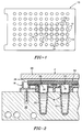
- Figure 1 is a top view of a cover in accordance with a first embodiment of the present invention.
- Figure 2 is a partial sectional view of a thermal cycler and reaction tube tray with the cover shown in Figure 1 installed on the reaction tubes.
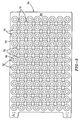
- Figure 3 is a top view of a cover in accordance with a second embodiment of the present invention.
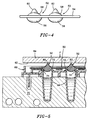
- Figure 4 is an enlarged side view of a portion of the second embodiment of the present invention shown in Figure 3.
- Figure 5 is a partial sectional view of a thermal cycler assembly and reaction tube tray using the cover in accordance with the second embodiment of the present invention.
- a first embodiment of the cover in accordance with the present invention is shown in a top view in Figure 1, and installed on an array of reaction tubes placed in a thermal cycler block in Figure 2.
- Cover 10 is a flexible sheet of preferably silicone rubber which comprises a planar array of reaction tube cover portions 12 arranged in a predetermined rectangular spatial arrangement corresponding to the centers of a corresponding planar array of reaction tubes held in a tray.
- a representative number of the cover portions are shown in Figure 1 in dashed lines.
- Interspersed between the cover portions 12 are a plurality of apertures 14.
- FIG. 2 illustrates a partial sectional view through a thermal cycler containing a tray 16 of reaction tubes 18 which extend into the thermal cycler block 20.
- Each of the tubes 18 contains a reaction mixture 22 up to a level preferably no higher than the upper surface of the thermal cycler block 20 and has an open mouth 24.
- Cover 10 has a thickness that is slightly greater than the distance between the mouth 24 of the tubes 18 and the upper surface 26 of the tray assembly 16. Thus, as a heated platen 28 is lowered onto the upper surface of the tray assembly 16, the cover 10 presses downward against the tops of the reaction tubes 18, pressing them into firm contact with the thermal cycler block 20. At the same time, cover 10 provides a seal over the mouth 24 of each of the tubes 18 by pressing against the annular upper surface 30 of the mouth 24 of each tube 18.
- the heated platen 28 is designed to heat the air around the portion of the reaction tubes 18 that extends above the block 30 to prevent vapor condensation in the upper portion of the tubes. Since the silicone rubber cover 10 is a thermal barrier, apertures 14 are critical to providing circulation of the air beneath the heated platen 28. When the heated platen rests against the upper edge of the tray 16, the captive air space is quickly heated and maintained at a temperature greater than that of the thermal cycler block through radiation and convective heat transfer through the apertures 14.
- the cover 10 in accordance with the first embodiment of the invention provides a single annular seal around the mouth of each tube in the array. The thickness of the cover 10 must be enough to protrude above the upper edge 26 of the tray 16.
- the thickness should not be so great as to reduce the heat transfer through the silicone rubber cover inside the annular sealed portion so as to prevent vapor condensation on the under side of the cover portions.
- a thickness of about 1/8th inch greater than the distance between the tube mouth 24 and the upper surface 26 of the tray 16 is believed to be about optimum.
- the apertures should preferably have a diameter of approximately 4 millimeters.
- the thickness of the cover should be as thin as possible while still providing an adequate thickness to provide an adequate seal for each tube in the array when the platen cover is lowered.
- the flexible plastic sheet material is preferably silicone rubber. However, any flexible plastic material having a high temperature withstand capability and a durometer range between 35 and 65 durometer, and preferably about a 50 durometer silicone rubber, is preferred. This type of material has a long life at high temperature.
- the sheet material has a thermal conductivity of at least .001 W/cm ⁇ °K and preferably is within a range of .002 to .004 W/cm ⁇ °K which prevents condensation on the underside of the cover exposed to the reaction tube contents, and is compatible with the PCR process.
- Cover 50 is a planar array of individual reaction tube covers or nodules 52 arranged in a predetermined rectangular spatial arrangement corresponding to the centers of a corresponding planar array of reaction tubes held in a tray.
- Each of the individual covers or nodules 52 is made of a flexible plastic material and held in the predetermined spaced relationship from each other by an integral web 54.
- Web 54 may be integral with nodules 52 and made of the same material or may be made of a different material with the nodules 52 molded or adhesively attached to the web 54 at appropriate locations.
- each of the nodules 52 preferably has a downwardly convex, e.g. dome-shaped, lower portion 56, though other surface shapes may be used.
- Nodule 52 has an upwardly convex upper portion 58 over the lower portion 56.
- Extending upward from the upper portion 58 is an integral nipple 60.
- the nipple 60 may be a generally rounded conical protrusion as illustrated in Figure 4, or may be a cylindrical post with a rounded tip. The purpose of the rounded tip on the nipple 60 is to preclude the nipple from adhering to the under surface 62 of the heated platen 64 illustrated in Figure 5 when the heated platen 64 is lowered with force F onto the cover 50.
- Figure 5 illustrates a partial sectional view through a thermal cycler containing a tray 66 of reaction tubes 68 extending into a thermal cycler block 70.
- nipples 60 are pressed downwardly to seat into and seal each of the tubes 68, and in turn press the tubes 68 into firm contact in thermal cycler block 70.
- the rounded upper tip of the nipples 60 is preferred to preclude a suction occurring against the underside 62 of the heated platen 64 as it is removed from engagement with the tray 66 following completion of the PCR protocol. This prevents the cover 52 from being inadvertently lifted with the platen 64.
- the heated platen 64 is designed to heat the air around the portion of the reaction tubes 68 that extends above block 70 to prevent vapor condensation in the upper portion of the tubes 68.
- Apertures 72 are provided between the rows and columns of nodules 52 as the silicone rubber cover, in accordance with the present invention, is a thermal insulator. These apertures permit radiative heat transfer and convective circulation of the air beneath the heated platen 64 and above the upper surface of the block 70.
- a captive air space in between is created which is quickly heated and maintained at a temperature greater than the block 70 temperature.
- the second embodiment of the cover in accordance with the present invention provides two separate seals on each reaction tube.
- the first is between the upper surface 72 of the mouth of the tube 68 and the portion of the web 54 around the base of the nodule 52.
- the second is between an annular portion of the hemispherical lower portion 56 and against the inside surface 74 around the mouth of the reaction tube 68.
- this second seal may be provided by a cylindrical extension of the convex lower portion so as to provide a larger contact surface for the seal.
- the cover 50 When the force F is removed from the heated platen 64 and the platen raised so that the tray 66 can be removed, the cover 50 remains in place on the array of tubes 68.
- the entire array of tubes 68 may be uncapped simply by lifting the cover 10 in one motion.
- the cover portion 12 or nodules 50 are spaced on 9 millimeter centers corresponding to the standard array of 96 reaction tubes.
- the apertures are about 4 millimeters in diameter. It is to be understood that other spacings and sizes may be utilized depending on the reaction tube tray design.
- the preferred silicon rubber must be chemically resistant to dilute nitric acid, dilute sodium hydroxide, sodium hypochlorite (bleach), and ethanol having material hardness of Shore A 50, and must be autoclavable. Silicone rubber is preferable in this application as it is inert to the PCR products and reagents, is autoclavable, and is washable in a hypochlorite solution without substantial deleterious effects.
- a suitable silicone rubber material may be obtained by High Tech Rubber Company, Anaheim, CA.
- the nodules may each have an internal filling of a high thermal conductivity material such as a metal "B-B" to increase the overall heat transfer through the nodules from the heated platen.
- the covers 10 and 50 in accordance with the present invention need not be utilized with a full tray of reaction tubes. For example, an array of 8 rows by 12 columns, totalling 96 tubes, may effectively be utilized with the cover in accordance with the present invention. However, the same sample tray containing any number of tubes will be adequately sealed with either of the covers in accordance with the present invention. Thus, the covers in accordance with the present invention can effectively replace the conventional cap strips and result in substantial time savings during handling.
- the illustrated embodiments of the covers 10 and 50 are rectangular arrays.
- the array may be a circular, other polygonal, or an annular arrangement, depending on the tray configuration.
- the apertures may be placed between linearly adjacent nodules or diagonally between them as shown in Figures 1 and 3.
- the holes need not be circular.
Abstract
Description
- This invention generally relates to chemical reaction tube covers, and more particularly to a cover for a two-dimensional array of reaction tubes preferably utilized in an instrument for performing polymerase chain reactions (PCR).
- This application is a continuation-in-part of U.S. Patent Application Serial No. 07/871,264, filed April 20, 1992, which is a continuation-in-part of U.S. Patent Application Serial Nos. 07/620,606, filed November 29, 1990, and 07/670,545, filed March 14, 1991, each of which is assigned to the assignee of the present invention, and each of which is incorporated herein by reference.
- Automated thermal cyclers for performing PCR simultaneously on a number of samples are disclosed in the patent applications mentioned above and in U.S. Patent No. 5,038,852. Briefly, PCR is an enzymatic process by which a small amount of specific DNA sequences can be greatly amplified in a relatively short period of time. The method utilizes two oligonucleotide primers that hybridize to opposite strands and flank the region of interest in the target DNA. A repetitive series of thermal cycles involving template denaturation, primer annealing, and the extension of the annealed primers by DNA polymerase results in the exponential accumulation of a specific DNA fragment whose termini are defined by the 5' ends of the primers.
- A reaction mixture made up of the target DNA to be amplified, oligonucleotide primers, buffers, nucleotide triphosphates, and preferably a thermostable enzyme such as Taq polymerase, are combined and placed in reaction tubes. The reaction mixture contained in the tubes is then subjected to a number of thermal transition and soak periods known as PCR protocols in a thermal cycler to generate the amplified target DNA.
- An array of reaction tubes is typically made up of up to either 48 or 96 tubes arranged in a 6 x 8 array or an 8 x 12 array in a tray. The array of tubes is placed in a metal thermal cycler block so that the lower portion of each tube is in intimate thermal contact with the block. The temperature of the block is then varied in accordance with the predetermined temperature/time profile of the PCR protocol for a predetermined number of cycles.
- The denaturation step of the PCR protocol involves heating and maintaining the reaction mixture to around 95°C to separate double stranded DNA into single strands. At this elevated temperature, evaporation becomes a problem. To prevent evaporation of the tube contents during the PCR process, either a layer of wax or oil is placed on top of the mixture in each tube or a cap is placed on each tube in conjunction with a heated cover.
- The caps are preferred over the oil or wax layer because application of such a layer is time consuming, messy, and invites mixture contamination. These caps may be separate individual caps or may be attached integrally to the tube. Alternatively, a series of plastic caps are connected together in linear strips of 8 or 12. Each one of the caps includes a tubular lower portion and an upwardly domed upper portion. The caps are connected together by an integral tab so as to form the strip of caps.
- A tray of reaction tubes is typically filled with appropriate sample fluids, and each individual cap in a single strip is inserted into a tube so that the domed portion is up and the tubular portion fits down inside the reaction tube to provide a seal. The caps may be removed by pulling up on one end of the individual cap strip, as the reaction tubes are held within the tray by a retainer. Installation of these conventional caps on the reaction tubes is a relatively tedious and time consuming process requiring specific insertion of the tubular portion of each cap in each individual tube.
- The tray of capped reaction tubes is inserted into a thermal cycler block and a heated platen cover is lowered over the block, pressing the domed caps downward to uniformly seat all of the reaction tubes and establish good thermal contact between each tube and the thermal cycler block. The heated platen cover provides a closed environment over the upper portions of the tubes projecting above the thermal cycler block. This heated platen cover is maintained during the thermal cycling protocol at a temperature greater than any of the thermal cycling temperatures so as to preclude vapor condensation within the upper portion of the tube or beneath the cap, both of which protrude above the body of the thermal cycler block. Thus, evaporative losses are prevented by the caps and internal vapor condensation is prevented by the elevated temperature under the platen cover.
- The heated platen cover also prevents refluxing which affects the temperature of the sample within the reaction tube. Refluxing is the cyclical evaporation and condensation within the enclosed space above the sample within the reaction tube. Refluxing will generally lower the sample temperature during the thermal cycling protocol.
- After the thermal cycling protocol has been completed, the tray of capped reaction tubes is removed from the thermal cycler and may be allowed to return to room temperature. The strips of caps are then removed from the tubes carefully so as to preclude cross-contamination between the tubes, and the array is transferred to other instruments for PCR product detection or further processing.
- The configuration of plastic caps consisting of a strip of individual domed caps is quite adequate for small scale PCR where high throughputs are not required. The design offers the advantage of isolating each individual reaction tube but can be tedious to position in place and to remove. Accordingly, there is a need for a full plate cover or blanket which would offer the user an easier and faster way of sealing an entire array of tubes and easier, more efficient access to the tubes at the end of the PCR process.
- The cover in accordance with the present invention is a planar array of reaction tube covers which are adapted to seal a plurality of reaction tubes arranged in a predetermined spatial arrangement. In its simplest form, the cover in accordance with the present invention is a flat sheet of flexible plastic material having a plurality of spaced apertures therethrough, forming between the apertures an array of cover portions, one for each of the reaction tubes in a predetermined spatial arrangement. This flat sheet cover is placed on top of the planar array of reaction tubes such that the apertures are positioned between the tubes and the cover portions over the individual tube tops. A heated platen is then lowered onto the cover over the reaction tubes, pressing the cover and the tubes into firm contact with the thermal cycler block, and the PCR process is performed. When the heated platen is removed, the cover is simply lifted off of the reaction tube array in a single motion requiring minimal time expenditure.
- This simplest form of the cover of the invention provides a single top seal around the upper lip of each of the reaction tubes. The apertures between the cover portions in the cover permit heated air to circulate between the tubes and from the heated platen downward toward the thermal cycler block to prevent vapor condensation within the portions of the reaction tubes extending above the thermal cycler block.
- A second, more preferred, embodiment comprises a sheet cover wherein the cover portions are flexible plastic nodules held in a predetermined spaced relationship from each other by a web. Each of the nodules is adapted to fit into and provide two seals on the mouth of a reaction tube. Each of the nodules has a downwardly convex lower portion and an upwardly convex upper portion directly over the lower portion. The web connecting each of the nodules has a plurality of apertures through the web spaced between the nodules to allow for thermal circulation below and above the cover.
- Where the spaced relationship is a planar array utilized to cover a two-dimensional rectangular array of reaction tubes held in a rectangular tray, the nodules are aligned in spaced linear rows and columns, with the apertures preferably diagonally between the nodules. The apertures between the nodules permit air to circulate between the heated platen and the upper sides of the reaction tubes extending above the thermal cycler block.
- Each nodule has outwardly convex upper and lower portions extending from the plane of a central sheet or web. The lower portion of each of the nodules is preferably of a hemispherical shape which has a diameter equal to or slightly greater than the inside diameter of the mouth of the reaction tube. This hemispherical shape permits each of the nodules to fit into and concentrically seal one of the tubes in two ways. First, the hemispherical portion fits down into the tube so that there is an annular seal around the inside surface of the tube adjacent the mouth. Second, the portion of the web around the outer perimeter or base of the hemispherical lower portion provides an annular planar seal against the top surface of the mouth of the tube.
- The upper portion of the nodule is outwardly convex and preferably has a central nipple extending upward from the upwardly convex portion. This nipple may be in the form of a cylindrical post, or, more preferably, a smooth, curved, dome-shaped protrusion extending vertically above the convex upper portion.
- Tests utilizing covers in accordance with the present invention in a Perkin-Elmer GeneAmp™ PCR System thermal cycler produce the same PCR results as tubes with the conventional individual cap strips discussed above without evidencing sample degradation. The covers of the invention maintain an effective seal on the tubes to prevent any liquid or vapor leakage. The nipple on the upper portion of the nodules does not stick to the heated platen cover and provides efficient downward force transfer to ensure that all of the reaction tubes are firmly seated within the thermal cycler block.
- These, and other advantages and features of the invention will become more apparent from a detailed reading of the following description when taken in conjunction with the appended claims.
- Figure 1 is a top view of a cover in accordance with a first embodiment of the present invention.
- Figure 2 is a partial sectional view of a thermal cycler and reaction tube tray with the cover shown in Figure 1 installed on the reaction tubes.
- Figure 3 is a top view of a cover in accordance with a second embodiment of the present invention.
- Figure 4 is an enlarged side view of a portion of the second embodiment of the present invention shown in Figure 3.
- Figure 5 is a partial sectional view of a thermal cycler assembly and reaction tube tray using the cover in accordance with the second embodiment of the present invention.
- A first embodiment of the cover in accordance with the present invention is shown in a top view in Figure 1, and installed on an array of reaction tubes placed in a thermal cycler block in Figure 2.
Cover 10 is a flexible sheet of preferably silicone rubber which comprises a planar array of reactiontube cover portions 12 arranged in a predetermined rectangular spatial arrangement corresponding to the centers of a corresponding planar array of reaction tubes held in a tray. A representative number of the cover portions are shown in Figure 1 in dashed lines. Interspersed between thecover portions 12 are a plurality ofapertures 14. - Figure 2 illustrates a partial sectional view through a thermal cycler containing a
tray 16 ofreaction tubes 18 which extend into thethermal cycler block 20. Each of thetubes 18 contains areaction mixture 22 up to a level preferably no higher than the upper surface of thethermal cycler block 20 and has anopen mouth 24. -
Cover 10 has a thickness that is slightly greater than the distance between themouth 24 of thetubes 18 and theupper surface 26 of thetray assembly 16. Thus, as aheated platen 28 is lowered onto the upper surface of thetray assembly 16, thecover 10 presses downward against the tops of thereaction tubes 18, pressing them into firm contact with thethermal cycler block 20. At the same time, cover 10 provides a seal over themouth 24 of each of thetubes 18 by pressing against the annularupper surface 30 of themouth 24 of eachtube 18. - The
heated platen 28 is designed to heat the air around the portion of thereaction tubes 18 that extends above theblock 30 to prevent vapor condensation in the upper portion of the tubes. Since thesilicone rubber cover 10 is a thermal barrier,apertures 14 are critical to providing circulation of the air beneath theheated platen 28. When the heated platen rests against the upper edge of thetray 16, the captive air space is quickly heated and maintained at a temperature greater than that of the thermal cycler block through radiation and convective heat transfer through theapertures 14. Thus, thecover 10 in accordance with the first embodiment of the invention provides a single annular seal around the mouth of each tube in the array. The thickness of thecover 10 must be enough to protrude above theupper edge 26 of thetray 16. However, the thickness should not be so great as to reduce the heat transfer through the silicone rubber cover inside the annular sealed portion so as to prevent vapor condensation on the under side of the cover portions. A thickness of about 1/8th inch greater than the distance between thetube mouth 24 and theupper surface 26 of thetray 16 is believed to be about optimum. - For a typical 8 x 12 array of reaction tubes on 9 millimeter centers, the apertures should preferably have a diameter of approximately 4 millimeters. The thickness of the cover should be as thin as possible while still providing an adequate thickness to provide an adequate seal for each tube in the array when the platen cover is lowered.
- The flexible plastic sheet material is preferably silicone rubber. However, any flexible plastic material having a high temperature withstand capability and a durometer range between 35 and 65 durometer, and preferably about a 50 durometer silicone rubber, is preferred. This type of material has a long life at high temperature. The sheet material has a thermal conductivity of at least .001 W/cm·°K and preferably is within a range of .002 to .004 W/cm·°K which prevents condensation on the underside of the cover exposed to the reaction tube contents, and is compatible with the PCR process.
- A second embodiment of the cover in accordance with the present invention is shown in a top view in Figure 3, and a partial side view in Figure 4.
Cover 50 is a planar array of individual reaction tube covers ornodules 52 arranged in a predetermined rectangular spatial arrangement corresponding to the centers of a corresponding planar array of reaction tubes held in a tray. Each of the individual covers ornodules 52 is made of a flexible plastic material and held in the predetermined spaced relationship from each other by anintegral web 54.Web 54 may be integral withnodules 52 and made of the same material or may be made of a different material with thenodules 52 molded or adhesively attached to theweb 54 at appropriate locations. - As best shown in Figure 4, each of the
nodules 52 preferably has a downwardly convex, e.g. dome-shaped,lower portion 56, though other surface shapes may be used.Nodule 52 has an upwardly convexupper portion 58 over thelower portion 56. Extending upward from theupper portion 58 is anintegral nipple 60. Thenipple 60 may be a generally rounded conical protrusion as illustrated in Figure 4, or may be a cylindrical post with a rounded tip. The purpose of the rounded tip on thenipple 60 is to preclude the nipple from adhering to theunder surface 62 of theheated platen 64 illustrated in Figure 5 when theheated platen 64 is lowered with force F onto thecover 50. - Figure 5 illustrates a partial sectional view through a thermal cycler containing a tray 66 of
reaction tubes 68 extending into a thermal cycler block 70. As aheated platen 64 is lowered onto tray 66,nipples 60 are pressed downwardly to seat into and seal each of thetubes 68, and in turn press thetubes 68 into firm contact in thermal cycler block 70. - The rounded upper tip of the
nipples 60 is preferred to preclude a suction occurring against theunderside 62 of theheated platen 64 as it is removed from engagement with the tray 66 following completion of the PCR protocol. This prevents thecover 52 from being inadvertently lifted with theplaten 64. - The
heated platen 64 is designed to heat the air around the portion of thereaction tubes 68 that extends above block 70 to prevent vapor condensation in the upper portion of thetubes 68.Apertures 72 are provided between the rows and columns ofnodules 52 as the silicone rubber cover, in accordance with the present invention, is a thermal insulator. These apertures permit radiative heat transfer and convective circulation of the air beneath theheated platen 64 and above the upper surface of the block 70. Thus, as theheated platen 64 rests against the upper edge of the tray 66, a captive air space in between is created which is quickly heated and maintained at a temperature greater than the block 70 temperature. - The second embodiment of the cover in accordance with the present invention provides two separate seals on each reaction tube. The first is between the
upper surface 72 of the mouth of thetube 68 and the portion of theweb 54 around the base of thenodule 52. The second is between an annular portion of the hemisphericallower portion 56 and against theinside surface 74 around the mouth of thereaction tube 68. In another embodiment, this second seal may be provided by a cylindrical extension of the convex lower portion so as to provide a larger contact surface for the seal. - When the force F is removed from the
heated platen 64 and the platen raised so that the tray 66 can be removed, thecover 50 remains in place on the array oftubes 68. The entire array oftubes 68 may be uncapped simply by lifting thecover 10 in one motion. Thus, installing and removing the covers is a simple step requiring minimum time while ensuring adequate sealing, minimizing operating time and thus providing a cost savings per analysis. - The
cover portion 12 ornodules 50 are spaced on 9 millimeter centers corresponding to the standard array of 96 reaction tubes. The apertures are about 4 millimeters in diameter. It is to be understood that other spacings and sizes may be utilized depending on the reaction tube tray design. The preferred silicon rubber must be chemically resistant to dilute nitric acid, dilute sodium hydroxide, sodium hypochlorite (bleach), and ethanol having material hardness ofShore A 50, and must be autoclavable. Silicone rubber is preferable in this application as it is inert to the PCR products and reagents, is autoclavable, and is washable in a hypochlorite solution without substantial deleterious effects. A suitable silicone rubber material may be obtained by High Tech Rubber Company, Anaheim, CA. - Other materials may also be utilized provided they are flexible, inert to reactions with the reagents utilized, and can withstand repeated thermal cycling to temperatures above 100°C. Also, the nodules may each have an internal filling of a high thermal conductivity material such as a metal "B-B" to increase the overall heat transfer through the nodules from the heated platen. The
covers - All of the embodiments of the cover provide a good hermetic seal on each of the tubes and prevents any leakage, operate so that the tubes may still remain oil free, are easy to remove from the plate and do not stick to the heated platen. While the invention has been described above with reference to a specific embodiment thereof, it is apparent that many changes, modifications, and variations can be made without departing from the inventive concept disclosed herein. For example, the illustrated embodiments of the
covers
Claims (13)
- A planar array of reaction tube covers adapted to seal a plurality of reaction tubes arranged in a predetermined spacial arrangement, said array comprising:
a plurality of nodules held in a predetermined spaced relationship from each other by a web, each of said nodules adapted to fit into and seal an open end of one of said reaction tubes, each of said nodules having a lower portion for fitting within said one end and an upwardly convex upper portion over said lower portion. - The array according to claim 1 wherein said portions are integrally connected to said web.
- The array according to claim 1 wherein said web has a plurality of apertures therethrough spaced between said nodules.
- The array according to claim 1 wherein said array is a molded unitary rubber body.
- The array according to claim 4 wherein said body is silicone rubber.
- The array according to claim 1 wherein said lower portion has a solid generally hemispherical shape.
- A planar array of reaction tube covers adapted to seal a plurality of reaction tubes arranged in a predetermined spacial arrangement, said array comprising:
a plurality of flexible plastic nodules connected in a predetermined spaced relationship from each other by a web, each of said nodules adapted to fit into and seal an open end of one of said tubes, each of said nodules having a downwardly convex lower portion, an upwardly convex upper portion over said lower portion, and a nipple extending upward from said upwardly convex portion. - The array according to claim 10 wherein said web has a plurality of apertures therethrough spaced between said nodules.
- The array according to claim 7 wherein said array is a molded unitary body made of silicone rubber.
- The array according to claim 9 wherein said nipple is centered above said upper and lower portions and has a dome shape.
- The array according to claim 7 wherein said lower portion has a generally hemispherical shape.
- An array of reaction tube covers adapted to seal a plurality of reaction tubes comprising a unitary body having a plurality of flexible plastic nodules, each adapted to seal one of said reaction tubes, each of said nodules being flexibly held in a predetermined planar spaced relationship from each other in rows and columns by an integral web having a plurality of apertures therethrough, each of said nodules having a downwardly convex generally hemispherical lower portion extending from said web, an upwardly convex upper portion extending from said web over said lower portion, and a centrally domed nipple extending upward from said upwardly convex portion.
- A planar array of reaction tube covers adapted to seal a plurality of reaction tubes arranged in a predetermined spatial arrangement comprising a flexible resilient sheet of plastic having a plurality of spaced cover portions arranged complimentary to said predetermined spatial arrangement and a plurality of apertures through said sheet between said cover portions.
Applications Claiming Priority (2)
| Application Number | Priority Date | Filing Date | Title |
|---|---|---|---|
| US08/002,559 US5282543A (en) | 1990-11-29 | 1993-01-11 | Cover for array of reaction tubes |
| US2559 | 1993-01-11 |
Publications (2)
| Publication Number | Publication Date |
|---|---|
| EP0606534A1 true EP0606534A1 (en) | 1994-07-20 |
| EP0606534B1 EP0606534B1 (en) | 1997-12-29 |
Family
ID=21701339
Family Applications (1)
| Application Number | Title | Priority Date | Filing Date |
|---|---|---|---|
| EP93115845A Expired - Lifetime EP0606534B1 (en) | 1993-01-11 | 1993-09-30 | Cover for array of reaction tubes |
Country Status (12)
| Country | Link |
|---|---|
| US (1) | US5282543A (en) |
| EP (1) | EP0606534B1 (en) |
| JP (1) | JP3415667B2 (en) |
| KR (1) | KR100306921B1 (en) |
| CN (1) | CN1114702C (en) |
| AT (1) | ATE161436T1 (en) |
| AU (1) | AU670839B2 (en) |
| CA (1) | CA2106183C (en) |
| DE (1) | DE69315970T2 (en) |
| DK (1) | DK0606534T3 (en) |
| IL (1) | IL107129A (en) |
| NZ (1) | NZ248834A (en) |
Cited By (8)
| Publication number | Priority date | Publication date | Assignee | Title |
|---|---|---|---|---|
| EP0737106A1 (en) * | 1993-04-19 | 1996-10-16 | SANADI, Ashok R. | Method and apparatus for preventing cross-contamination of multi-well plates |
| WO1996039481A2 (en) * | 1995-05-31 | 1996-12-12 | Chiron Corporation | Releasable multiwell plate cover |
| WO1998040159A2 (en) * | 1997-03-10 | 1998-09-17 | Trega Biosciences, Inc. | Apparatus and method for combinatorial chemistry synthesis |
| US6051191A (en) * | 1996-11-25 | 2000-04-18 | Porvair Plc | Microplates |
| EP1286891A2 (en) * | 2000-05-11 | 2003-03-05 | Irm, Llc | Specimen plate lid and method of using |
| US7332348B2 (en) | 2003-02-28 | 2008-02-19 | Applera Corporation | Sample substrate having a divided sample chamber and method of loading thereof |
| DE102010040685A1 (en) * | 2010-09-14 | 2012-03-15 | Hamilton Bonaduz Ag | Temperature control device for the thermal consolidation of drug beads |
| US9175333B2 (en) | 2003-06-23 | 2015-11-03 | Applied Biosystems, Llc | Caps for sample wells and microcards for biological materials |
Families Citing this family (85)
| Publication number | Priority date | Publication date | Assignee | Title |
|---|---|---|---|---|
| US7560273B2 (en) * | 2002-07-23 | 2009-07-14 | Applied Biosystems, Llc | Slip cover for heated platen assembly |
| US6258325B1 (en) * | 1993-04-19 | 2001-07-10 | Ashok Ramesh Sanadi | Method and apparatus for preventing cross-contamination of multi-well test plates |
| CA2130517C (en) * | 1993-09-10 | 1999-10-05 | Walter Fassbind | Array of reaction containers for an apparatus for automatic performance of temperature cycles |
| US5840573A (en) * | 1994-02-01 | 1998-11-24 | Fields; Robert E. | Molecular analyzer and method of use |
| DE4412286A1 (en) * | 1994-04-09 | 1995-10-12 | Boehringer Mannheim Gmbh | System for contamination-free processing of reaction processes |
| US5456360A (en) * | 1994-09-30 | 1995-10-10 | The Perkin-Elmer Corporation | Holder assembly for reaction tubes |
| US6121048A (en) * | 1994-10-18 | 2000-09-19 | Zaffaroni; Alejandro C. | Method of conducting a plurality of reactions |
| US5721136A (en) * | 1994-11-09 | 1998-02-24 | Mj Research, Inc. | Sealing device for thermal cycling vessels |
| DE4440294A1 (en) * | 1994-11-11 | 1996-05-15 | Boehringer Mannheim Gmbh | System for the incubation of sample liquids |
| US5576197A (en) * | 1995-04-07 | 1996-11-19 | Molecular Bio-Products | Polymerase chain reaction container and methods of using the same |
| US5885529A (en) * | 1996-06-28 | 1999-03-23 | Dpc Cirrus, Inc. | Automated immunoassay analyzer |
| US5632399A (en) * | 1996-06-28 | 1997-05-27 | Dpc Cirrus Inc. | Self-sealing reagent container and reagent container system |
| NO304355B1 (en) | 1997-02-20 | 1998-12-07 | Sinvent As | Multi-autoclave for methodical, automated synthesis of zeolites and other compounds |
| US7133726B1 (en) * | 1997-03-28 | 2006-11-07 | Applera Corporation | Thermal cycler for PCR |
| US6132684A (en) * | 1997-10-31 | 2000-10-17 | Becton Dickinson And Company | Sample tube holder |
| GB9804383D0 (en) * | 1998-03-03 | 1998-04-22 | Chromacol Ltd | Closures |
| ES2229465T3 (en) | 1998-05-04 | 2005-04-16 | F. Hoffmann-La Roche Ag | TREMO-VARIATOR THAT HAS A COVER THAT IS AUTOMATICALLY PLACED IN POSITION. |
| US7115231B1 (en) | 1998-06-09 | 2006-10-03 | Symyx Technologies, Inc. | Parallel reactor with knife-edge seal |
| US6117391A (en) * | 1998-06-18 | 2000-09-12 | Bayer Corporation | Cup handling subsystem for an automated clinical chemistry analyzer system |
| US6419827B1 (en) | 1998-10-29 | 2002-07-16 | Applera Corporation | Purification apparatus and method |
| US6159368A (en) * | 1998-10-29 | 2000-12-12 | The Perkin-Elmer Corporation | Multi-well microfiltration apparatus |
| US6896849B2 (en) * | 1998-10-29 | 2005-05-24 | Applera Corporation | Manually-operable multi-well microfiltration apparatus and method |
| US6906292B2 (en) * | 1998-10-29 | 2005-06-14 | Applera Corporation | Sample tray heater module |
| US6136273A (en) * | 1998-11-18 | 2000-10-24 | Matrix Technologies Corporation | Closure device for laboratory receptacles |
| US6486401B1 (en) | 1999-02-22 | 2002-11-26 | Tekcel, Inc. | Multi well plate cover and assembly |
| US6558628B1 (en) | 1999-03-05 | 2003-05-06 | Specialty Silicone Products, Inc. | Compartment cover, kit and method for forming the same |
| EP1045038A1 (en) * | 1999-04-08 | 2000-10-18 | Hans-Knöll-Institut Für Naturstoff-Forschung E.V. | Rapid heat block thermocycler |
| US6555389B1 (en) | 1999-05-11 | 2003-04-29 | Aclara Biosciences, Inc. | Sample evaporative control |
| NL1012996C2 (en) * | 1999-09-08 | 2001-03-12 | Micronic B V | Sealing mat for sealing test tubes. |
| ATE237399T1 (en) | 1999-09-29 | 2003-05-15 | Tecan Trading Ag | THERMOCYCLER AND LIFTING ELEMENT FOR MICROTITER PLATE |
| JP3390377B2 (en) | 1999-10-05 | 2003-03-24 | 株式会社日立製作所 | Reactor |
| US6988546B1 (en) * | 1999-11-26 | 2006-01-24 | Eyela-Chino Inc. | Sample temperature regulator |
| US7169355B1 (en) | 2000-02-02 | 2007-01-30 | Applera Corporation | Apparatus and method for ejecting sample well trays |
| DE20006546U1 (en) * | 2000-04-08 | 2001-08-23 | Mwg Biotech Ag | Cover mat |
| US6994827B2 (en) * | 2000-06-03 | 2006-02-07 | Symyx Technologies, Inc. | Parallel semicontinuous or continuous reactors |
| US7347977B2 (en) * | 2000-06-08 | 2008-03-25 | Eppendorf Ag | Microtitration plate |
| DE10066211B4 (en) * | 2000-06-08 | 2008-06-26 | Eppendorf Ag | microtiter plate |
| DE10028536B4 (en) * | 2000-06-08 | 2004-08-19 | Eppendorf Ag | microtiter plate |
| US6439036B1 (en) | 2000-06-13 | 2002-08-27 | Symyx Technologics, Inc. | Method for evaluating a test fluid |
| US6455007B1 (en) | 2000-06-13 | 2002-09-24 | Symyx Technologies, Inc. | Apparatus and method for testing compositions in contact with a porous medium |
| US6939516B2 (en) * | 2000-09-29 | 2005-09-06 | Becton, Dickinson And Company | Multi-well plate cover and assembly adapted for mechanical manipulation |
| US6896848B1 (en) * | 2000-12-19 | 2005-05-24 | Tekcel, Inc. | Microplate cover assembly |
| US6767514B2 (en) * | 2001-03-05 | 2004-07-27 | Baskerville Reactors And Autoclaves Limited | Test apparatus |
| EP1386432A4 (en) * | 2001-03-21 | 2009-07-15 | John A Stine | An access and routing protocol for ad hoc networks using synchronous collision resolution and node state dissemination |
| US6426215B1 (en) | 2001-04-06 | 2002-07-30 | Pe Corporation (Ny) | PCR plate cover and maintaining device |
| WO2003004596A1 (en) * | 2001-07-06 | 2003-01-16 | Precision System Science Co., Ltd. | Reaction container and reaction device |
| GB0118620D0 (en) * | 2001-07-31 | 2001-09-19 | Macaulay Land Use Res Inst The | Apparatus and method |
| WO2003015918A2 (en) * | 2001-08-16 | 2003-02-27 | Weidmann Plastics Technology Ag | Method for the production of a sealing cover and sealing cover produced by said method |
| US6682703B2 (en) * | 2001-09-05 | 2004-01-27 | Irm, Llc | Parallel reaction devices |
| US20030072685A1 (en) * | 2001-10-11 | 2003-04-17 | Goldman Jeffrey A. | Heat conducting sample block |
| US20030098271A1 (en) * | 2001-11-26 | 2003-05-29 | Ralph Somack | Capsule and tray systems for combined sample collection, archiving, purification, and PCR |
| WO2003061832A1 (en) * | 2002-01-16 | 2003-07-31 | Robbins Scientific Corporation | Low volume micro-plate and volume-limiting plugs |
| US20040009583A1 (en) * | 2002-02-05 | 2004-01-15 | Genome Therapeutics Corporation | Seal for microtiter plate and methods of use thereof |
| US20040053318A1 (en) * | 2002-09-17 | 2004-03-18 | Mcwilliams Diana R. | Preservation of RNA and reverse transcriptase during automated liquid handling |
| US20040115720A1 (en) * | 2002-11-08 | 2004-06-17 | Mcwilliams Diana R. | High throughput automatic nucleic acid isolation and quantitation methods |
| US7169602B2 (en) | 2002-12-04 | 2007-01-30 | Applera Corporation | Sample substrate for use in biological testing and method for filling a sample substrate |
| US8641987B2 (en) | 2003-01-24 | 2014-02-04 | Applied Biosystems, Llc | Sample chamber array and method for processing a biological sample |
| US20060029948A1 (en) * | 2003-09-19 | 2006-02-09 | Gary Lim | Sealing cover and dye compatibility selection |
| US20060013984A1 (en) * | 2003-09-19 | 2006-01-19 | Donald Sandell | Film preparation for seal applicator |
| WO2005029041A2 (en) * | 2003-09-19 | 2005-03-31 | Applera Corporation | High density sequence detection methods and apparatus |
| US20050280811A1 (en) * | 2003-09-19 | 2005-12-22 | Donald Sandell | Grooved high density plate |
| US20050226780A1 (en) * | 2003-09-19 | 2005-10-13 | Donald Sandell | Manual seal applicator |
| US20060011305A1 (en) * | 2003-09-19 | 2006-01-19 | Donald Sandell | Automated seal applicator |
| US20050232818A1 (en) * | 2003-09-19 | 2005-10-20 | Donald Sandell | Single sheet seal applicator and cartridge |
| US7341872B1 (en) * | 2004-04-29 | 2008-03-11 | Uop Llc | Multiautoclave with set of vessels for combinatorial synthesis of zeolites and other materials |
| KR100637030B1 (en) * | 2004-11-30 | 2006-10-23 | (주)바이오넥스 | Apparatus for minimizing evaporation and/or condensation occurring in tubes of multi-well plate mounted to pcr thermo cycler |
| JP4697781B2 (en) * | 2005-03-30 | 2011-06-08 | 株式会社島津製作所 | Reaction vessel processing equipment |
| EP2040983A4 (en) * | 2006-06-26 | 2011-08-03 | Life Technologies Corp | Compressible transparent sealing for open microplates |
| EP1961484B1 (en) * | 2007-02-13 | 2016-07-20 | Eppendorf Ag | Cover for sample with homogeneous pressure application |
| JP5200517B2 (en) * | 2007-12-04 | 2013-06-05 | 凸版印刷株式会社 | Reaction vessel |
| IT1397110B1 (en) * | 2008-12-29 | 2012-12-28 | St Microelectronics Rousset | SELF-SEALING MICROREACTOR AND METHOD TO CARRY OUT A REACTION |
| GB0903623D0 (en) * | 2009-03-03 | 2009-04-15 | 4Titude Ltd | Sealing multiwell plates |
| US8701913B2 (en) * | 2009-04-16 | 2014-04-22 | Meridian Biosciences, Inc. | Dual-reservoir container with an integral seal cap |
| US8202497B2 (en) * | 2009-06-25 | 2012-06-19 | Yoko Nakahana | Lid element array and a micro tube array for sample storage including the same |
| CA2724106C (en) * | 2009-12-10 | 2018-04-17 | F. Hoffmann-La Roche Ag | Multiwell plate and lid |
| GB201012490D0 (en) | 2010-07-26 | 2010-09-08 | Randox Lab Ltd | Sealed well assembly, cartridge thereof, and apparatus and method for opening a sealed well assembly |
| WO2012078930A2 (en) * | 2010-12-08 | 2012-06-14 | Life Technologies Corporation | Control systems and methods for biological applications |
| US20140154722A1 (en) * | 2011-08-12 | 2014-06-05 | Solidus Biosciences, Inc. | Apparatus for analyzing biomaterial |
| USD735881S1 (en) | 2012-10-22 | 2015-08-04 | Qiagen Gaithersburg, Inc. | Tube strip holder for automated processing systems |
| US9180461B2 (en) | 2012-10-22 | 2015-11-10 | Qiagen Gaithersburg, Inc. | Condensation-reducing incubation cover |
| GB201506445D0 (en) | 2015-04-16 | 2015-06-03 | Insphero Ag | System for propagating cells |
| GB2556623B (en) * | 2016-10-27 | 2021-07-28 | 4Titude Ltd | Improved sealing products for indvidual wells in multi-well arrays |
| US11648564B2 (en) | 2018-02-02 | 2023-05-16 | Covaris, Llc | Well plate drier and cover |
| CN109358016A (en) * | 2018-07-06 | 2019-02-19 | 湖南大学 | A kind of method and apparatus of hand-held pressure pot combination colorimetric cylinder rapid-digestion measurement water body total nitrogen |
| CN116445261B (en) * | 2023-05-31 | 2023-09-08 | 山东东大检测科技有限公司 | PCR reaction tube and pipettor |
Citations (6)
| Publication number | Priority date | Publication date | Assignee | Title |
|---|---|---|---|---|
| GB1113010A (en) * | 1966-04-28 | 1968-05-08 | Luedi & Cie A G | Test tube closure |
| DE2507835A1 (en) * | 1975-02-24 | 1976-09-02 | Joachim Dr Med Happ | Holder for large numbers of test-tubes - with single-piece lid sealing all tubes |
| EP0285496A1 (en) * | 1987-03-23 | 1988-10-05 | Ire Medgenix S.A. | Assembling and closing device for immunological test tubes |
| EP0339769A1 (en) * | 1988-04-28 | 1989-11-02 | Costar Corporation | Multi-well filter strip and composite assemblies |
| EP0388159A2 (en) * | 1989-03-15 | 1990-09-19 | Seiko Instruments Inc. | Apparatus for sealing liquid within cavities |
| EP0488769A2 (en) * | 1990-11-29 | 1992-06-03 | The Perkin-Elmer Corporation | Thermal cycler for automatic performance of the polymerase chain reaction with close temperature control |
Family Cites Families (6)
| Publication number | Priority date | Publication date | Assignee | Title |
|---|---|---|---|---|
| US3302854A (en) * | 1961-09-26 | 1967-02-07 | Sweetheart Plastics | Cluster of covers |
| US3206017A (en) * | 1962-01-09 | 1965-09-14 | Sweetheart Plastics | Cluster of container covers |
| US3366265A (en) * | 1966-05-09 | 1968-01-30 | Best Plastics Inc | Multiple unit package |
| DE2603683A1 (en) * | 1976-01-31 | 1977-08-11 | Loo Hans Michael Van De Dr Rer | Covered stand for small reaction vessels - with cover fixed against stoppers of vessels to maintain them in position |
| DE3037826C2 (en) * | 1980-10-07 | 1985-06-05 | Drägerwerk AG, 2400 Lübeck | Sampling tubes with caps |
| US5038852A (en) * | 1986-02-25 | 1991-08-13 | Cetus Corporation | Apparatus and method for performing automated amplification of nucleic acid sequences and assays using heating and cooling steps |
-
1993
- 1993-01-11 US US08/002,559 patent/US5282543A/en not_active Expired - Lifetime
- 1993-09-14 CA CA002106183A patent/CA2106183C/en not_active Expired - Fee Related
- 1993-09-27 IL IL10712993A patent/IL107129A/en not_active IP Right Cessation
- 1993-09-30 DE DE69315970T patent/DE69315970T2/en not_active Expired - Fee Related
- 1993-09-30 EP EP93115845A patent/EP0606534B1/en not_active Expired - Lifetime
- 1993-09-30 AT AT93115845T patent/ATE161436T1/en not_active IP Right Cessation
- 1993-09-30 DK DK93115845.5T patent/DK0606534T3/en active
- 1993-10-01 NZ NZ248834A patent/NZ248834A/en unknown
-
1994
- 1994-01-07 AU AU53088/94A patent/AU670839B2/en not_active Ceased
- 1994-01-11 KR KR1019940000347A patent/KR100306921B1/en not_active IP Right Cessation
- 1994-01-11 CN CN94100828A patent/CN1114702C/en not_active Expired - Fee Related
- 1994-01-11 JP JP00120194A patent/JP3415667B2/en not_active Expired - Fee Related
Patent Citations (6)
| Publication number | Priority date | Publication date | Assignee | Title |
|---|---|---|---|---|
| GB1113010A (en) * | 1966-04-28 | 1968-05-08 | Luedi & Cie A G | Test tube closure |
| DE2507835A1 (en) * | 1975-02-24 | 1976-09-02 | Joachim Dr Med Happ | Holder for large numbers of test-tubes - with single-piece lid sealing all tubes |
| EP0285496A1 (en) * | 1987-03-23 | 1988-10-05 | Ire Medgenix S.A. | Assembling and closing device for immunological test tubes |
| EP0339769A1 (en) * | 1988-04-28 | 1989-11-02 | Costar Corporation | Multi-well filter strip and composite assemblies |
| EP0388159A2 (en) * | 1989-03-15 | 1990-09-19 | Seiko Instruments Inc. | Apparatus for sealing liquid within cavities |
| EP0488769A2 (en) * | 1990-11-29 | 1992-06-03 | The Perkin-Elmer Corporation | Thermal cycler for automatic performance of the polymerase chain reaction with close temperature control |
Cited By (15)
| Publication number | Priority date | Publication date | Assignee | Title |
|---|---|---|---|---|
| EP0737106A1 (en) * | 1993-04-19 | 1996-10-16 | SANADI, Ashok R. | Method and apparatus for preventing cross-contamination of multi-well plates |
| EP0737106A4 (en) * | 1993-04-19 | 1996-10-23 | ||
| WO1996039481A2 (en) * | 1995-05-31 | 1996-12-12 | Chiron Corporation | Releasable multiwell plate cover |
| WO1996039481A3 (en) * | 1995-05-31 | 1997-05-01 | Chiron Corp | Releasable multiwell plate cover |
| US6051191A (en) * | 1996-11-25 | 2000-04-18 | Porvair Plc | Microplates |
| US6045755A (en) * | 1997-03-10 | 2000-04-04 | Trega Biosciences,, Inc. | Apparatus and method for combinatorial chemistry synthesis |
| WO1998040159A3 (en) * | 1997-03-10 | 1999-01-07 | Trega Biosciences Inc | Apparatus and method for combinatorial chemistry synthesis |
| WO1998040159A2 (en) * | 1997-03-10 | 1998-09-17 | Trega Biosciences, Inc. | Apparatus and method for combinatorial chemistry synthesis |
| EP1286891A2 (en) * | 2000-05-11 | 2003-03-05 | Irm, Llc | Specimen plate lid and method of using |
| EP1286891A4 (en) * | 2000-05-11 | 2003-05-07 | Irm Llc | Specimen plate lid and method of using |
| US7332348B2 (en) | 2003-02-28 | 2008-02-19 | Applera Corporation | Sample substrate having a divided sample chamber and method of loading thereof |
| US8628730B2 (en) | 2003-02-28 | 2014-01-14 | Applied Biosystems, Llc | Sample substrate having a divided sample chamber and method of loading thereof |
| US9175333B2 (en) | 2003-06-23 | 2015-11-03 | Applied Biosystems, Llc | Caps for sample wells and microcards for biological materials |
| US9914123B2 (en) | 2003-06-23 | 2018-03-13 | Applied Biosystems, Llc | Caps for sample wells and microcards for biological materials |
| DE102010040685A1 (en) * | 2010-09-14 | 2012-03-15 | Hamilton Bonaduz Ag | Temperature control device for the thermal consolidation of drug beads |
Also Published As
| Publication number | Publication date |
|---|---|
| ATE161436T1 (en) | 1998-01-15 |
| CA2106183C (en) | 2005-07-05 |
| KR940018132A (en) | 1994-08-16 |
| IL107129A0 (en) | 1993-12-28 |
| IL107129A (en) | 1996-11-14 |
| CN1114702C (en) | 2003-07-16 |
| JP3415667B2 (en) | 2003-06-09 |
| CA2106183A1 (en) | 1994-07-12 |
| DE69315970T2 (en) | 1998-04-16 |
| NZ248834A (en) | 1996-03-26 |
| KR100306921B1 (en) | 2002-03-21 |
| AU5308894A (en) | 1994-07-14 |
| DK0606534T3 (en) | 1998-05-25 |
| JPH075180A (en) | 1995-01-10 |
| DE69315970D1 (en) | 1998-02-05 |
| AU670839B2 (en) | 1996-08-01 |
| US5282543A (en) | 1994-02-01 |
| EP0606534B1 (en) | 1997-12-29 |
| CN1092109A (en) | 1994-09-14 |
Similar Documents
| Publication | Publication Date | Title |
|---|---|---|
| US5282543A (en) | Cover for array of reaction tubes | |
| US5710381A (en) | Two piece holder for PCR sample tubes | |
| KR100286792B1 (en) | Normal Polymerase Chain Reaction Amplification System | |
| CA2159374C (en) | Holder assembly for reaction tubes | |
| US5604130A (en) | Releasable multiwell plate cover | |
| US7452712B2 (en) | Sample block apparatus and method of maintaining a microcard on a sample block | |
| US6949376B2 (en) | Nucleic acid amplification reaction station for disposable test devices | |
| US20040009583A1 (en) | Seal for microtiter plate and methods of use thereof | |
| JP2008245643A (en) | Slip cover for heated platen assembly | |
| US6660232B1 (en) | Multi-well assay plate and plate holder and method of assembling the same | |
| US11944975B2 (en) | Thermal cycler systems and methods of use | |
| US6063579A (en) | Alignment mechanism | |
| JP2002528108A5 (en) | ||
| EP1133359A1 (en) | Ultrathin-walled multiwell plate for heat block thermocycling | |
| EP3157680A1 (en) | Molecular analysis system and use thereof | |
| EP2150798B1 (en) | Thermoelectric device and heat sink assembly with reduced edge heat loss | |
| KR20060060069A (en) | Apparatus for minimizing evaporation and/or condensation occurring in tubes of multi-well plate mounted to pcr thermo cycler |
Legal Events
| Date | Code | Title | Description |
|---|---|---|---|
| PUAI | Public reference made under article 153(3) epc to a published international application that has entered the european phase |
Free format text: ORIGINAL CODE: 0009012 |
|
| AK | Designated contracting states |
Kind code of ref document: A1 Designated state(s): AT BE CH DE DK ES FR GB GR IE IT LI LU NL SE |
|
| 17P | Request for examination filed |
Effective date: 19941004 |
|
| 17Q | First examination report despatched |
Effective date: 19951005 |
|
| GRAG | Despatch of communication of intention to grant |
Free format text: ORIGINAL CODE: EPIDOS AGRA |
|
| GRAH | Despatch of communication of intention to grant a patent |
Free format text: ORIGINAL CODE: EPIDOS IGRA |
|
| GRAH | Despatch of communication of intention to grant a patent |
Free format text: ORIGINAL CODE: EPIDOS IGRA |
|
| GRAA | (expected) grant |
Free format text: ORIGINAL CODE: 0009210 |
|
| AK | Designated contracting states |
Kind code of ref document: B1 Designated state(s): AT BE CH DE DK ES FR GB GR IE IT LI LU NL SE |
|
| PG25 | Lapsed in a contracting state [announced via postgrant information from national office to epo] |
Ref country code: GR Free format text: LAPSE BECAUSE OF FAILURE TO SUBMIT A TRANSLATION OF THE DESCRIPTION OR TO PAY THE FEE WITHIN THE PRESCRIBED TIME-LIMIT Effective date: 19971229 Ref country code: ES Free format text: THE PATENT HAS BEEN ANNULLED BY A DECISION OF A NATIONAL AUTHORITY Effective date: 19971229 |
|
| REF | Corresponds to: |
Ref document number: 161436 Country of ref document: AT Date of ref document: 19980115 Kind code of ref document: T |
|
| REG | Reference to a national code |
Ref country code: CH Ref legal event code: NV Representative=s name: PATENTANWALTSBUERO JEAN HUNZIKER Ref country code: CH Ref legal event code: EP |
|
| REF | Corresponds to: |
Ref document number: 69315970 Country of ref document: DE Date of ref document: 19980205 |
|
| ITF | It: translation for a ep patent filed |
Owner name: ING. A. GIAMBROCONO & C. S.R.L. |
|
| ET | Fr: translation filed | ||
| REG | Reference to a national code |
Ref country code: DK Ref legal event code: T3 |
|
| REG | Reference to a national code |
Ref country code: IE Ref legal event code: FG4D Free format text: 78041 |
|
| PG25 | Lapsed in a contracting state [announced via postgrant information from national office to epo] |
Ref country code: LU Free format text: LAPSE BECAUSE OF NON-PAYMENT OF DUE FEES Effective date: 19980930 |
|
| PLBE | No opposition filed within time limit |
Free format text: ORIGINAL CODE: 0009261 |
|
| STAA | Information on the status of an ep patent application or granted ep patent |
Free format text: STATUS: NO OPPOSITION FILED WITHIN TIME LIMIT |
|
| 26N | No opposition filed | ||
| REG | Reference to a national code |
Ref country code: GB Ref legal event code: IF02 |
|
| NLS | Nl: assignments of ep-patents |
Owner name: APPLERA CORPORATION |
|
| NLT1 | Nl: modifications of names registered in virtue of documents presented to the patent office pursuant to art. 16 a, paragraph 1 |
Owner name: PE CORPORATION (NY) |
|
| REG | Reference to a national code |
Ref country code: CH Ref legal event code: PUE Owner name: APPLERA CORPORATION Free format text: PE CORPORATION (NY)#761 MAIN AVENUE#NORWALK, CT 06859 (US) -TRANSFER TO- APPLERA CORPORATION#850 LINCOLN CENTRE DRIVE#FOSTER CITY, CA 94404 (US) Ref country code: CH Ref legal event code: PFA Owner name: PE CORPORATION (NY) Free format text: THE PERKIN-ELMER CORPORATION#761 MAIN AVENUE#NORWALK CONNECTICUT 06859-0074 (US) -TRANSFER TO- PE CORPORATION (NY)#761 MAIN AVENUE#NORWALK, CT 06859 (US) |
|
| REG | Reference to a national code |
Ref country code: FR Ref legal event code: TP |
|
| PGFP | Annual fee paid to national office [announced via postgrant information from national office to epo] |
Ref country code: NL Payment date: 20040829 Year of fee payment: 12 |
|
| PGFP | Annual fee paid to national office [announced via postgrant information from national office to epo] |
Ref country code: AT Payment date: 20040901 Year of fee payment: 12 |
|
| PGFP | Annual fee paid to national office [announced via postgrant information from national office to epo] |
Ref country code: FR Payment date: 20040920 Year of fee payment: 12 |
|
| PGFP | Annual fee paid to national office [announced via postgrant information from national office to epo] |
Ref country code: SE Payment date: 20040921 Year of fee payment: 12 |
|
| PGFP | Annual fee paid to national office [announced via postgrant information from national office to epo] |
Ref country code: GB Payment date: 20040922 Year of fee payment: 12 |
|
| PGFP | Annual fee paid to national office [announced via postgrant information from national office to epo] |
Ref country code: CH Payment date: 20040924 Year of fee payment: 12 Ref country code: DK Payment date: 20040924 Year of fee payment: 12 |
|
| PGFP | Annual fee paid to national office [announced via postgrant information from national office to epo] |
Ref country code: IE Payment date: 20040927 Year of fee payment: 12 |
|
| PGFP | Annual fee paid to national office [announced via postgrant information from national office to epo] |
Ref country code: BE Payment date: 20041021 Year of fee payment: 12 |
|
| PGFP | Annual fee paid to national office [announced via postgrant information from national office to epo] |
Ref country code: DE Payment date: 20041102 Year of fee payment: 12 |
|
| REG | Reference to a national code |
Ref country code: GB Ref legal event code: 732E |
|
| PG25 | Lapsed in a contracting state [announced via postgrant information from national office to epo] |
Ref country code: LI Free format text: LAPSE BECAUSE OF NON-PAYMENT OF DUE FEES Effective date: 20050930 Ref country code: IT Free format text: LAPSE BECAUSE OF NON-PAYMENT OF DUE FEES;WARNING: LAPSES OF ITALIAN PATENTS WITH EFFECTIVE DATE BEFORE 2007 MAY HAVE OCCURRED AT ANY TIME BEFORE 2007. THE CORRECT EFFECTIVE DATE MAY BE DIFFERENT FROM THE ONE RECORDED. Effective date: 20050930 Ref country code: IE Free format text: LAPSE BECAUSE OF NON-PAYMENT OF DUE FEES Effective date: 20050930 Ref country code: GB Free format text: LAPSE BECAUSE OF NON-PAYMENT OF DUE FEES Effective date: 20050930 Ref country code: DK Free format text: LAPSE BECAUSE OF NON-PAYMENT OF DUE FEES Effective date: 20050930 Ref country code: CH Free format text: LAPSE BECAUSE OF NON-PAYMENT OF DUE FEES Effective date: 20050930 Ref country code: BE Free format text: LAPSE BECAUSE OF NON-PAYMENT OF DUE FEES Effective date: 20050930 Ref country code: AT Free format text: LAPSE BECAUSE OF NON-PAYMENT OF DUE FEES Effective date: 20050930 |
|
| PG25 | Lapsed in a contracting state [announced via postgrant information from national office to epo] |
Ref country code: SE Free format text: LAPSE BECAUSE OF NON-PAYMENT OF DUE FEES Effective date: 20051001 |
|
| PG25 | Lapsed in a contracting state [announced via postgrant information from national office to epo] |
Ref country code: NL Free format text: LAPSE BECAUSE OF NON-PAYMENT OF DUE FEES Effective date: 20060401 Ref country code: DE Free format text: LAPSE BECAUSE OF NON-PAYMENT OF DUE FEES Effective date: 20060401 |
|
| REG | Reference to a national code |
Ref country code: CH Ref legal event code: PL Ref country code: DK Ref legal event code: EBP |
|
| GBPC | Gb: european patent ceased through non-payment of renewal fee |
Effective date: 20050930 |
|
| PG25 | Lapsed in a contracting state [announced via postgrant information from national office to epo] |
Ref country code: FR Free format text: LAPSE BECAUSE OF NON-PAYMENT OF DUE FEES Effective date: 20060531 |
|
| NLV4 | Nl: lapsed or anulled due to non-payment of the annual fee |
Effective date: 20060401 |
|
| EUG | Se: european patent has lapsed | ||
| REG | Reference to a national code |
Ref country code: IE Ref legal event code: MM4A |
|
| REG | Reference to a national code |
Ref country code: FR Ref legal event code: ST Effective date: 20060531 |
|
| BERE | Be: lapsed |
Owner name: THE *PERKIN-ELMER CORP. Effective date: 20050930 |