EP0604077A2 - Multiple beam diode laser output scanning system - Google Patents
Multiple beam diode laser output scanning system Download PDFInfo
- Publication number
- EP0604077A2 EP0604077A2 EP93309969A EP93309969A EP0604077A2 EP 0604077 A2 EP0604077 A2 EP 0604077A2 EP 93309969 A EP93309969 A EP 93309969A EP 93309969 A EP93309969 A EP 93309969A EP 0604077 A2 EP0604077 A2 EP 0604077A2
- Authority
- EP
- European Patent Office
- Prior art keywords
- beams
- laser
- optical path
- group
- laser beams
- Prior art date
- Legal status (The legal status is an assumption and is not a legal conclusion. Google has not performed a legal analysis and makes no representation as to the accuracy of the status listed.)
- Granted
Links
Images


Classifications
-
- H—ELECTRICITY
- H04—ELECTRIC COMMUNICATION TECHNIQUE
- H04N—PICTORIAL COMMUNICATION, e.g. TELEVISION
- H04N1/00—Scanning, transmission or reproduction of documents or the like, e.g. facsimile transmission; Details thereof
- H04N1/46—Colour picture communication systems
- H04N1/50—Picture reproducers
- H04N1/506—Reproducing the colour component signals picture-sequentially, e.g. with reproducing heads spaced apart from one another in the subscanning direction
-
- G—PHYSICS
- G02—OPTICS
- G02B—OPTICAL ELEMENTS, SYSTEMS OR APPARATUS
- G02B26/00—Optical devices or arrangements for the control of light using movable or deformable optical elements
- G02B26/08—Optical devices or arrangements for the control of light using movable or deformable optical elements for controlling the direction of light
- G02B26/10—Scanning systems
- G02B26/12—Scanning systems using multifaceted mirrors
- G02B26/123—Multibeam scanners, e.g. using multiple light sources or beam splitters
Definitions
- the present invention relates to multiple beam output scanning systems.
- a latent image is formed on a charged photoreceptor, usually by raster sweeping a modulated laser beam across the photoreceptor.
- the latent image is then used to create a permanent image by transferring and fusing toner that was electrostatically attracted to the latent image onto a recording medium.
- ROSs Raster Output Scanners
- the beam sweep speed problem becomes very important when printing in color at high speed. This is because a color xerographic printer overlaps separate images for each color, called a system color, that is printed. While a dual color printer uses only two images, a full color printer typically requires four images: one for each of the three primary colors of cyan, magenta, yellow, and an additional image for black.
- Multipass printers by sequentially transferring and fusing overlapped system colors onto a single recording medium that is passed multiple times, once for each system color, through the printer.
- Multistation and single station/multiposition printers have greater printed page output than multipass printers operating at the same raster sweep speed.
- the commercial introduction of multistation and single station/multiposition printers has been delayed by 1) cost problems, at least partially related to the cost of multiple xerographic stations, each of which has its own ROS, and 2) image quality problems, at least partially related to the difficulty of producing separate images on each photoreceptor and then registering (overlapping) the separate images to produce a color output.
- Proposed prior art multistation printers e.g. US-A-4,847,642 usually use an individual ROS (each comprised of a separate polygon mirror, lens system, and related optical components) for each station. Problems with such systems include the high cost of producing nearly identical multiple ROSs and the difficulty of registering the system colors.
- the present invention provides a ROS according to claim 1 of the appended claims.
- the invention provides for a raster output scanning (ROS) apparatus simultaneously sweeps a plurality of orthogonally polarized and dissimilar wavelength laser beams having common optical axes from common mirror surface areas.
- the swept laser beams are subsequently separated by a combination of polarizers and optical filters.
- the polarizers and optical filters are the absorption type and therefore transmit only the beam with the desired polarization or wavelength.
- the transmitted laser beams are subsequently directed onto associated photoreceptive regions of a single station/multiposition printer, or onto associated photoreceptors of a multistation printer.
- dimensioned and registered spots are readily obtained on all photoreceptive regions, beneficially by establishing a substantially similar optical path length for each laser beam.
- the inventive apparatus can be implemented in several ways. For example, in a first embodiment two orthogonally polarized, individually modulated, coaxial laser beams are split into two groups of beams by an optical beam splitter. Each group of beams then passes through an associated absorption type polarization selective optical filter. The two optical filters are controlled such that one optical filter passes the laser beam having one polarization and the other optical filter passes the orthogonally polarized laser beam. The separated laser beams may then be directed by directing means onto one or more photosensors.
- the directing means may include a means for equalizing the optical path lengths from said beam splitter to the or each photoreceptor.
- the equalizing means includes a mirror.
- the invention further provides a ROS according to claim 5 of the appended claims.
- a bundle of orthogonally polarized and dissimilar wavelength coaxial laser beams is split into multiple groups of beams by an optical beam splitter.
- Each group of beams then passes through individual polarizers which transmit similarly polarized laser beams while absorbing the orthogonally polarized beams.
- Those transmitted beams are then split by an optical beam splitter into one or more sets of identically polarized, but dissimilar wavelength, beams which pass through one or more optical filters.
- Each optical filter transmits one beam at a specified wavelength while absorbing the others.
- the bundle of laser beams is separated into individual beams.
- the apparatus preferably further includes a second optical filter for receiving said fourth group of beams, said second optical filter for absorbing said fourth group's beams that are derived from said first laser beam and for directing said fourth group's beams that are derived from said second laser beam onto a third optical path.
- the apparatus may further include a second beam separator receiving said second group of beams, said second beam separator for absorbing said second group's beams that are derived from said first and second laser beams and for directing said second group's beams that are derived from said third and fourth laser beams onto a fourth optical path; a third beam splitter receiving said beams on said fourth optical path, said third beam splitter for splitting its received laser beams into fifth and sixth groups of beams that are derived from said third and fourth laser beams; a third optical filter for receiving said fifth group of beams, said third optical filter for absorbing said fifth group's beams that are derived from said fourth laser beam and for directing said fifth group's beams that are derived from said third laser beam onto a fifth optical path; and a fourth optical filter for receiving said sixth group of beams, said fourth optical filter for absorbing said sixth group's beams that are derived from said third laser beam and for directing said sixth group's beams that are derived from said fourth laser beam onto a sixth optical path.
- the apparatus may further include one or more photoreceptors; and means for directing said laser beams on said second, third, fifth and sixth optical paths onto (1) first, second, third, and fourth photoreceptors, respectively, or (2) a single photoreceptor.
- the directing means includes means, preferably including a mirror, for equalizing the optical path lengths of at least two of said beams on said second, third, fifth and sixth optical paths from said first beam splitter to the, or their respective, photoreceptor(s).
- the invention further provides ROS according to claim 6 of the appended claims.
- This embodiment first splits the bundle of coaxial laser beams into a plurality of bundles by using one or more optical beam splitters. Each bundle of laser beams is then passed through a combination comprised of a polarizer and an optical filter. Each polarizer/filter combination transmits one component beam of the bundle, corresponding to a unique combination of polarization and wavelength, while absorbing the others. In this way, separate and isolated beams are obtained.
- the described embodiments beneficially include devices, such as mirrors, to set each laser beam's optical path length the same.
- the apparatus further includes a second beam separator for receiving said fourth group of beams, said second beam separator for absorbing said fourth group's beam that are derived from said first laser beam and for directing said fourth group's beam that is derived from said third beam onto a third optical path.
- a second beam separator for receiving said fourth group of beams, said second beam separator for absorbing said fourth group's beam that are derived from said first laser beam and for directing said fourth group's beam that is derived from said third beam onto a third optical path.
- the apparatus may further include a second optical filter receiving said second group of beams, said second optical filter for absorbing said second group's beams that are derived from said first and third laser beams and for directing said second group's beams that are derived from said second and fourth laser beams onto a fourth optical path; a third beam splitter receiving said beams on said fourth optical path, said third beam splitter for splitting its received beams into fifth and sixth groups of beams that are derived from said second and fourth laser beams; a third beam separator for receiving said fifth group of beams, said third beam separator for absorbing said fifth group's beam that is derived from said fourth laser beam and for directing said fifth group's beam that is derived from said second beam onto a fifth optical path, and a fourth beam separator for receiving said sixth group of beams, said fourth beam separator for absorbing said sixth group's beam that is derived from said second laser beam and for directing said sixth group's beam that are derived from said fourth beam onto a sixth optical path.
- the apparatus may further include one or more photoreceptors; and means for directing said laser beams on said second, third, fifth and sixth optical paths onto (1) first, second, third, and fourth photoreceptors, respectively, or (2) onto a single photoreceptor.
- the directing means includes means, preferably including a mirror, for equalizing the optical path lengths of at least two of said laser beams on said second, third, fifth and sixth optical paths from said first beam splitter to the, or their respective, photoreceptor(s).
- the invention further provides a printer according to claim 7 of the appended claims.
- the printer has directing means which preferably includes a means for equalizing the optical path length along said first and third optical paths with that along said second and fourth optical paths.
- the invention further provides a method of separating individual laser beams according to claims 8, 9 and 10 of the appended claims.
- absorptive polarizers and optical filters improves on the prior art teachings by reducing the cost and complexity of the scanning apparatus while improving optical performance.
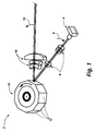
- a basic raster output scanner 2 used in the illustrated embodiments of the present invention is described with reference to FIG. 1.
- the raster output scanner 2 includes a laser source 4 that outputs multiple laser beams 6 from a substantially common spatial location. While FIG. 1 show four beams 6, some of the described embodiments use a laser source 4 that outputs only two beams. For clarity, only the chief rays of the beams are shown. Each beam may be independently modulated with data appropriate to expose a photoreceptive element with a desired image.
- An input optical system 8 directs the laser beams 6 onto overlapping, coaxial optical paths such that they illuminate common areas of a rotating polygon mirror 10 having a plurality of facets 12.
- the polygon mirror 10 repeatedly and simultaneously deflects the laser beams in the direction indicated by the arrow 16.
- the deflected laser beams are input to a set of imaging and correction optics 18 that focuses the laser beams and corrects for errors such as polygon angle error and wobble.
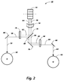
- the raster output scanner 2 (not all components of which are shown in FIG. 2) is used in a first embodiment apparatus 50 illustrated in FIG. 2.
- the raster output scanner 2 outputs only two laser beams (instead of four as shown in FIG. 1) that are designated 54 and 56. Again, as in FIG. 1, only the chief rays are shown.
- the beams have substantially the same optical wavelength, but are linearly polarized in orthogonal directions in the plane perpendicular to their propagation direction.
- the laser beams 54 and 56 are, respectively, divided into beams 58 and 60 and into beams 62 and 64 by a beam splitter 70.
- the laser beams 58 and 60 have substantially equal intensities, as do the laser beams 62 and 64.
- the beam splitter 70 is a partially transparent metallic film or multiple layer dielectric film constructed such that half of the intensity of an incident optical beam is transmitted while the other half is reflected. Such beam splitters are well known to those skilled in the applicable arts and are frequently used optical components.
- the laser beams 58 and 62 pass to a polarizer 74 that has transmission characteristics as shown in FIG. 3.
- the optical polarizer 74 is made from a material which absorbs light polarized in a particular direction while transmitting light polarized in the orthogonal direction.
- the polarizer 74 is aligned such that it absorbs beam 62 and transmits beam 58.
- beams 60 and 64 reflect off a mirror 76 and pass through an absorptive polarizer 78.
- Polarizer 78 which has the same transmission characteristics as the polarizer 74, is aligned such that it absorbs beam 60 and transmits beam 64.
- a mirror 80 reflects the laser beam 64 onto a photoreceptor 82, while a mirror 86 reflects the laser beam 58 onto a photoreceptor 90.
- the apparatus 50 is useful for two color printing since the image created on each photoreceptor corresponds to a different system color.
- the optical components 70, 76, 80, and 86 are positioned and oriented such that the optical path lengths from the laser source 4 (not shown in FIG. 2) to the photoreceptors 82 and 90 are substantially equal.
- the dual laser beam apparatus of FIG. 2 uses a laser device 4 that generates coaxially overlapping, cross-polarized laser beams.
- the laser device 4 may be either a monolithic diode laser array, or it may be two non-monolithic diode lasers closely spaced in a single integrated package. Orthogonality of the linearly polarized beams may be established either by the relative orientation of the two laser chips within the package, or by the relative orientation of the linearly polarized beams emitted by a monolithic laser array, as disclosed in U.S. Patent applications, Serial Nos. 07/948,524 and 07/948,522. With either type of source, the laser device 4 provides a substantially common spatial origin for both laser beams.
- the polarizers 74 and 78 have optical transmission/reflection characteristics as shown in FIG. 3.
- Polarizers of the absorption-type commonly known as dichroic polarizers, are well known to those in the applicable arts. Reference may be made to E.H. Land, Journ. of the Optical Society of America, vol. 41, beginning on pp. 957 (1951). Polarizers of this type are often made by embedding a dichroic polarizing material in a plastic sheet. Their polarization properties are relatively insensitive to changes in the wavelength and angle of the incident light. Consequently they enable improved optical performance at reduced cost when used in a multiple beam scanning apparatus as disclosed in the present invention.
- the apparatus illustrated in FIG. 2 readily produces similarly dimensioned beams at the beam splitter 70.
- the problem of maintaining equal optical path lengths for each beam reduces to the much simpler problem of maintaining substantially equal optical path lengths from the splitter 70 to the photoreceptors 82 and 90.
- Equal optical path lengths are set by properly positioning mirrors 76, 80, and 86. Further, registration problems are reduced since the characteristics of the mirror surface area and the related optics which sweep and form both beams are common to both. Furthermore, since both beams are nominally at the same wavelength, the beam forming optics do not have to be designed to simultaneously focus multiple wavelengths at the same distance.
- a two color xerographic print may be produced. Although details of the structure and operation of such means are beyond the scope of the present disclosure, they are well known to those skilled in the art.
- FIG. 4 shows of a second embodiment apparatus 100 according to the present invention.
- Apparatus 100 is a single station/multiposition printer that using the raster output scanner 2 (including polygon 10 and optics 18), simultaneously deflects the two laser beams 54 and 56 across spatially separated regions of one moving photoreceptor 108.
- each laser beam has nominally the same optical wavelength but is orthogonally polarized with respect to the other laser beam.
- the laser beams 54 and 56 are divided into beams 58 and 60, and into beams 62 and 64 by the beam splitter 70. Again, the laser beams 58 and 60, and 62 and 64 have substantially equal intensities.
- the laser beams 58 and 62 pass to the polarizer 74, again aligned such that it absorbs beam 62 while transmitting beam 58.
- the beams 60 and 64 reflect off the mirror 76 and pass to the polarizer 78, again aligned such that it absorbs beam 60 and transmits beam 64.
- mirrors 162 and 164 direct the laser beam 58 onto an area of the photoreceptor 108.
- Mirrors 168 and 170 direct laser beam 64 onto a separate area of the photoreceptor 108.
- a two color xerographic print may be produced.
- FIG. 5 shows a simplified, schematic view of a third embodiment apparatus 200 in which four laser beams, designated laser beams 212, 214, 216, and 218, are simultaneously scanned across four moving photoreceptors. Once again, only the chief rays are shown.
- the apparatus 200 is a multiple station printer which uses the raster output scanner 2 of FIG. 1 (including polygon 10, and optics 18, and laser device 4) to produce the four laser beams (not all components of the raster output scanner 2 are shown in FIG. 5).
- Two of the beams, i.e. laser beams 214 and 216 have the same wavelength, about 680 nanometers.
- the other two laser beams, i.e. laser beams 212 and 218, have the same wavelength, about 625 nm.
- the laser beams 212 and 214 are polarized in the same direction, which is orthogonal to the polarization of laser beams 216 and 218.
- the overlapping beams 212, 214, 216, and 218 are split into a first group of beams comprised of beams 222, 224, 226, and 228, and into a second group of beams comprised of beams 232, 234, 236, and 238 via a beam splitter 240.
- the intensities of the groups are substantially equal.
- the beam splitter 240 is a partially transparent metallic film or a multiple layer dielectric film, as discussed above with respect to the beam splitter 70.
- the reflected group of beams, i.e. beams 222, 224, 226, and 228, are input to an absorption-type optical polarizer 245, while the transmitted group, i.e. beams 232, 234, 236, and 238, reflect off a mirror 246 and are then input to an absorption-type optical polarizer 247.
- the polarizer 245, which has transmission characteristics as shown in FIG. 3, is aligned such that it absorbs beams 226 and 228 (which are derived from beams 216 and 218, respectively).
- the polarizer 247 which also has transmission characteristics shown in FIG. 3, is orientated to block beams 232 and 234 (which are derived from beams 212 and 214, respectively).
- the laser beams 222 and 224 are respectively divided into beams 252 and 262, and into beams 254 and 264 by a beam splitter 270.
- the intensities of beams 252 and 254 are substantially equal to the intensities of beams 262 and 264, respectively.
- the laser beams 236 and 238 are respectively divided into 1) beams 256 and 266 and 2) into beams 258 and 268 by a beam splitter 280.
- the intensities of beams 256 and 258 are substantially equal to the intensities of beams 266 and 268, respectively.
- the laser beams 252 and 254 are input to an optical filter 282, while laser beams 262 and 264 first reflect off a mirror 283 and are then input to an optical filter 284.
- laser beams 256 and 258 are input to an optical filter 288 while laser beams 266 and 268 first reflect off a mirror 285 and are then input to an optical filter 286.
- the optical filters 282 and 288 have the characteristics shown in FIG. 6 (discussed below), while optical filters 284 and 286 have the characteristics shown in FIG. 7 (discussed below).
- the optical filter 282 absorbs beam 254 and transmits beam 252 while the optical filter 284 absorbs the beam 262 and transmits beam 264.
- the optical filter 286 absorbs beam 268 and transmits beam 266, while the optical filter 288 absorbs beam 256 and transmits laser beam 258.
- Mirrors 292, 294, 296, and 298 respectively reflect the now isolated laser beams 252, 264, 266, and 258 onto photoreceptors 302, 304, 306, and 308. Since each laser beam is independently modulated with image information, distinct latent images are exposed onto each photoreceptor. Thus the apparatus 200 may be used for full color reproduction if the image on each photoreceptor corresponds to a different system color.
- the apparatus of FIG. 5 uses a laser device 4 (shown in FIG. 1) that generates four coaxially overlapping, cross-polarized laser beams of two dissimilar wavelengths using either a monolithic diode laser array or four non-monolithic diode lasers closely spaced in a single integrated package.
- the use of two wavelengths (instead of four as in US-A-5,243,359) considerably simplifies the construction of the laser device and reduces the requirements placed on the photoreceptive elements.
- Orthogonality of the linearly polarized beams is established either by the relative orientation of the laser chips within a single integrated package, or by the relative orientation of the linearly polarized beams emitted by a monolithic laser array, as disclosed in the previously mentioned USSNs 07/948,524 and 07/948,522. With either type of source, laser device 4 effectively provides a substantially common spatial origin for both laser beams.
- the optical filters 282, 284, 286, and 288 have characteristics as shown in either FIG. 6 and or FIG. 7.
- the optical characteristic of each filter is chosen to block the laser beams of one wavelength while transmitting laser beams of a different wavelength.
- the filter of FIG. 6 substantially absorbs a beam at 680 nanometers while transmitting a beam at 625 nanometers.
- the filter of FIG. 7 absorbs a beam at 625 nanometers while transmitting a beam at 680 nanometers.
- the curve 406 represents the characteristics of the optical filter when light strikes at a 45° angle of incidence
- curve 408 represents the filter's characteristics when light strikes at a 60° angle of incidence.
- the locations of the polarizers and optical filters in FIG. 5 can be interchanged.
- the coaxially bundled beams are first split to produce two groups of beams. Each group is then applied to a polarizer. The beams from the polarizers are then resplit and applied to wavelength selective optical filters. The resulting four beams may then be input to one or more photoreceptors.
- Other embodiments are also possible and are meant to be included in the scope of this invention.
- each single laser beam (such as beam 214) can be replaced by plural laser beams (beneficially from a laser diode array) having similar wavelengths and polarizations.
- the multiple beams which replace each single beam must differ from the other multiple beams in either wavelength or polarization.
- Two laser diode arrays of N lasers each can be fabricated using staggered lasers grown on a grooved substrate as described in US-A-4,786,918.
- Such other sections may include means for modulating the laser beams, a photoreceptive belt or drum, means for moving the photoreceptor, means for charging the photoreceptor, means for forming a latent image on the photoreceptor, means for transferring the latent image to paper, means for erasing the latent image from the photoreceptor, means for cleaning the photoreceptor, paper transport means, and means for fusing the image onto the paper.
Abstract
Description
- The present invention relates to multiple beam output scanning systems.
- In xerographic printing a latent image is formed on a charged photoreceptor, usually by raster sweeping a modulated laser beam across the photoreceptor. The latent image is then used to create a permanent image by transferring and fusing toner that was electrostatically attracted to the latent image onto a recording medium.
- While xerographic printing has been successful, problems arise when attempting to print at very high speed. As printing speed increases, it becomes more and more difficult to sweep the laser beam as fast as is required. The most common sweeping method is to deflect the laser beam from a rotating mirror. Thus one way of increasing the sweep speed is to rotate the mirror faster. However, extremely fast mirror rotation requires an expensive drive motor, expensive bearings, and a powerful laser.
- Other techniques of increasing the beam sweep speed include 1) sweeping the laser beam with a multifaceted, rotating polygon mirror, and/or 2) sweeping several laser beams simultaneously. Rotating polygon mirrors and their related optics are so common that they are generically referred to as Raster Output Scanners (ROSs). Printers that sweep several beams simultaneously are commonly referred to as multiple beam printers.
- The beam sweep speed problem becomes very important when printing in color at high speed. This is because a color xerographic printer overlaps separate images for each color, called a system color, that is printed. While a dual color printer uses only two images, a full color printer typically requires four images: one for each of the three primary colors of cyan, magenta, yellow, and an additional image for black.
- Color prints are currently produced, in "multipass printers", by sequentially transferring and fusing overlapped system colors onto a single recording medium that is passed multiple times, once for each system color, through the printer. Conceptually it is possible to imprint multiple colors on a recording medium in one pass by using a sequence of xerographic stations, one for each system color. If each station is associated with a separate photoreceptor, the printer is referred to as a multistation printer; if the stations use different positions on the same photoreceptor, the printer is referred to as a single station/multiposition printer.
- Multistation and single station/multiposition printers have greater printed page output than multipass printers operating at the same raster sweep speed. However, the commercial introduction of multistation and single station/multiposition printers has been delayed by 1) cost problems, at least partially related to the cost of multiple xerographic stations, each of which has its own ROS, and 2) image quality problems, at least partially related to the difficulty of producing separate images on each photoreceptor and then registering (overlapping) the separate images to produce a color output.
- Proposed prior art multistation printers (e.g. US-A-4,847,642) usually use an individual ROS (each comprised of a separate polygon mirror, lens system, and related optical components) for each station. Problems with such systems include the high cost of producing nearly identical multiple ROSs and the difficulty of registering the system colors.
- A partial solution to the problems of multistation xerographic systems with individual ROSs is disclosed in US-A-4,591,903, which shows (Figure 6) a printer having multiple recording stations and multiple lens systems, but only one rotating polygon mirror. Thus, the cost of the system is reduced. However, differences in the lenses and mirror surfaces could still cause problems with the registration of the different latent images.
- Another approach to overcoming the problems of multistation printers having individual ROSs is disclosed in US-A-4,962,312. That patent teaches spatially overlapping a plurality of beams using an optical beam combiner, deflecting the overlapped beams using a single polygon mirror, separating the deflected beams using an optical filter (and polarizers if more than two beams are used), and directing the separated beams onto associated photoreceptors. The advantage of overlapping the laser beams is a significant cost reduction since the ROS is shared. It is believed that a commercial embodiment of the apparatus disclosed in US-A-4,962,312 would be rather complicated and expensive, especially if four system colors are to be printed. The use of optical beam combiners to overlap beams so that they have similar optical axes and similar sized spots is believed to be difficult, expensive, and time consuming.
- Accordingly, there is a need for an improved apparatus that simultaneously deflects and separates multiple, orthogonally polarized and dissimilar wavelength laser beams having substantially common optical axes. The apparatus should produce similarly dimensioned spots that readily can be brought into registration.
- The present invention provides a ROS according to claim 1 of the appended claims.
- In particular, the invention provides for a raster output scanning (ROS) apparatus simultaneously sweeps a plurality of orthogonally polarized and dissimilar wavelength laser beams having common optical axes from common mirror surface areas. The swept laser beams are subsequently separated by a combination of polarizers and optical filters. The polarizers and optical filters are the absorption type and therefore transmit only the beam with the desired polarization or wavelength. The transmitted laser beams are subsequently directed onto associated photoreceptive regions of a single station/multiposition printer, or onto associated photoreceptors of a multistation printer. Similarly dimensioned and registered spots are readily obtained on all photoreceptive regions, beneficially by establishing a substantially similar optical path length for each laser beam.
- The inventive apparatus can be implemented in several ways. For example, in a first embodiment two orthogonally polarized, individually modulated, coaxial laser beams are split into two groups of beams by an optical beam splitter. Each group of beams then passes through an associated absorption type polarization selective optical filter. The two optical filters are controlled such that one optical filter passes the laser beam having one polarization and the other optical filter passes the orthogonally polarized laser beam. The separated laser beams may then be directed by directing means onto one or more photosensors.
- The directing means may include a means for equalizing the optical path lengths from said beam splitter to the or each photoreceptor. Preferably, the equalizing means includes a mirror.
- The invention further provides a ROS according to claim 5 of the appended claims.
- In this embodiment, a bundle of orthogonally polarized and dissimilar wavelength coaxial laser beams is split into multiple groups of beams by an optical beam splitter. Each group of beams then passes through individual polarizers which transmit similarly polarized laser beams while absorbing the orthogonally polarized beams. Those transmitted beams are then split by an optical beam splitter into one or more sets of identically polarized, but dissimilar wavelength, beams which pass through one or more optical filters. Each optical filter transmits one beam at a specified wavelength while absorbing the others. Thus the bundle of laser beams is separated into individual beams.
- The apparatus preferably further includes a second optical filter for receiving said fourth group of beams, said second optical filter for absorbing said fourth group's beams that are derived from said first laser beam and for directing said fourth group's beams that are derived from said second laser beam onto a third optical path.
- The apparatus may further include a second beam separator receiving said second group of beams, said second beam separator for absorbing said second group's beams that are derived from said first and second laser beams and for directing said second group's beams that are derived from said third and fourth laser beams onto a fourth optical path; a third beam splitter receiving said beams on said fourth optical path, said third beam splitter for splitting its received laser beams into fifth and sixth groups of beams that are derived from said third and fourth laser beams; a third optical filter for receiving said fifth group of beams, said third optical filter for absorbing said fifth group's beams that are derived from said fourth laser beam and for directing said fifth group's beams that are derived from said third laser beam onto a fifth optical path; and a fourth optical filter for receiving said sixth group of beams, said fourth optical filter for absorbing said sixth group's beams that are derived from said third laser beam and for directing said sixth group's beams that are derived from said fourth laser beam onto a sixth optical path.
- The apparatus may further include one or more photoreceptors; and means for directing said laser beams on said second, third, fifth and sixth optical paths onto (1) first, second, third, and fourth photoreceptors, respectively, or (2) a single photoreceptor.
- The directing means includes means, preferably including a mirror, for equalizing the optical path lengths of at least two of said beams on said second, third, fifth and sixth optical paths from said first beam splitter to the, or their respective, photoreceptor(s).
- The invention further provides ROS according to
claim 6 of the appended claims. - This embodiment first splits the bundle of coaxial laser beams into a plurality of bundles by using one or more optical beam splitters. Each bundle of laser beams is then passed through a combination comprised of a polarizer and an optical filter. Each polarizer/filter combination transmits one component beam of the bundle, corresponding to a unique combination of polarization and wavelength, while absorbing the others. In this way, separate and isolated beams are obtained. The described embodiments beneficially include devices, such as mirrors, to set each laser beam's optical path length the same.
- Preferably, the apparatus further includes a second beam separator for receiving said fourth group of beams, said second beam separator for absorbing said fourth group's beam that are derived from said first laser beam and for directing said fourth group's beam that is derived from said third beam onto a third optical path.
- The apparatus may further include a second optical filter receiving said second group of beams, said second optical filter for absorbing said second group's beams that are derived from said first and third laser beams and for directing said second group's beams that are derived from said second and fourth laser beams onto a fourth optical path; a third beam splitter receiving said beams on said fourth optical path, said third beam splitter for splitting its received beams into fifth and sixth groups of beams that are derived from said second and fourth laser beams; a third beam separator for receiving said fifth group of beams, said third beam separator for absorbing said fifth group's beam that is derived from said fourth laser beam and for directing said fifth group's beam that is derived from said second beam onto a fifth optical path, and a fourth beam separator for receiving said sixth group of beams, said fourth beam separator for absorbing said sixth group's beam that is derived from said second laser beam and for directing said sixth group's beam that are derived from said fourth beam onto a sixth optical path.
- The apparatus may further include one or more photoreceptors; and means for directing said laser beams on said second, third, fifth and sixth optical paths onto (1) first, second, third, and fourth photoreceptors, respectively, or (2) onto a single photoreceptor.
- Preferably, the directing means includes means, preferably including a mirror, for equalizing the optical path lengths of at least two of said laser beams on said second, third, fifth and sixth optical paths from said first beam splitter to the, or their respective, photoreceptor(s).
- The invention further provides a printer according to claim 7 of the appended claims.
- The printer has directing means which preferably includes a means for equalizing the optical path length along said first and third optical paths with that along said second and fourth optical paths.
- The invention further provides a method of separating individual laser beams according to
claims - It is an aim of this invention to utilize absorptive polarizers and optical filters to separate laser beams from a bundle of orthogonally polarized and distinctly different wavelength laser beams in a scanning apparatus which simultaneously deflects the bundled laser beams. The use of absorptive polarizers and optical filters improves on the prior art teachings by reducing the cost and complexity of the scanning apparatus while improving optical performance.
- Embodiments of the invention will now be described, by way of example, with reference to the accompanying drawings, in which:
- FIG. 1 shows a simplified perspective and schematic view of a raster output scanner (ROS) used in the various illustrated embodiments of the present invention;
- FIG. 2 shows a simplified schematic view of a dual laser beam raster output scanning (ROS) apparatus according to a first embodiment of the present invention;
- FIG. 3 shows the transmission characteristics of an absorption-type polarizer;
- FIG. 4 shows a simplified schematic view of a dual laser beam raster output scanning apparatus according to a second embodiment of the present invention;
- FIG. 5 shows a simplified schematic view of a four laser beam raster output scanner (ROS) apparatus according to a third embodiment of the present invention;
- FIG. 6 shows the transmission characteristics of a first bandpass absorption type optical filter; and
- FIG. 7 shows the transmission characteristics of a second bandpass absorption type optical filter.
- In general, like reference numerals denote like elements in each of the figures.
- A basic
raster output scanner 2 used in the illustrated embodiments of the present invention is described with reference to FIG. 1. Theraster output scanner 2 includes a laser source 4 that outputsmultiple laser beams 6 from a substantially common spatial location. While FIG. 1 show fourbeams 6, some of the described embodiments use a laser source 4 that outputs only two beams. For clarity, only the chief rays of the beams are shown. Each beam may be independently modulated with data appropriate to expose a photoreceptive element with a desired image. - An input
optical system 8 directs thelaser beams 6 onto overlapping, coaxial optical paths such that they illuminate common areas of arotating polygon mirror 10 having a plurality offacets 12. Thepolygon mirror 10 repeatedly and simultaneously deflects the laser beams in the direction indicated by thearrow 16. The deflected laser beams are input to a set of imaging andcorrection optics 18 that focuses the laser beams and corrects for errors such as polygon angle error and wobble. - The raster output scanner 2 (not all components of which are shown in FIG. 2) is used in a
first embodiment apparatus 50 illustrated in FIG. 2. In this embodiment, theraster output scanner 2 outputs only two laser beams (instead of four as shown in FIG. 1) that are designated 54 and 56. Again, as in FIG. 1, only the chief rays are shown. In this embodiment the beams have substantially the same optical wavelength, but are linearly polarized in orthogonal directions in the plane perpendicular to their propagation direction. After passing through thecorrection optics 18 thelaser beams beams beams beam splitter 70. In this embodiment thelaser beams laser beams - The
beam splitter 70 is a partially transparent metallic film or multiple layer dielectric film constructed such that half of the intensity of an incident optical beam is transmitted while the other half is reflected. Such beam splitters are well known to those skilled in the applicable arts and are frequently used optical components. After reflection from thesplitter 70, thelaser beams polarizer 74 that has transmission characteristics as shown in FIG. 3. Theoptical polarizer 74 is made from a material which absorbs light polarized in a particular direction while transmitting light polarized in the orthogonal direction. Thepolarizer 74 is aligned such that it absorbsbeam 62 and transmitsbeam 58. Similarly, after transmission by thebeam splitter 70, beams 60 and 64 reflect off amirror 76 and pass through anabsorptive polarizer 78.Polarizer 78, which has the same transmission characteristics as thepolarizer 74, is aligned such that it absorbsbeam 60 and transmitsbeam 64. Amirror 80 reflects thelaser beam 64 onto aphotoreceptor 82, while amirror 86 reflects thelaser beam 58 onto aphotoreceptor 90. - The
apparatus 50 is useful for two color printing since the image created on each photoreceptor corresponds to a different system color. Theoptical components photoreceptors - As previously mentioned, the
polarizers - By simultaneously sweeping two, coaxial laser beams from the same spatial location, the apparatus illustrated in FIG. 2 readily produces similarly dimensioned beams at the
beam splitter 70. Thus the problem of maintaining equal optical path lengths for each beam reduces to the much simpler problem of maintaining substantially equal optical path lengths from thesplitter 70 to thephotoreceptors - By incorporating means for transferring the images on the
photoreceptors - FIG. 4 shows of a
second embodiment apparatus 100 according to the present invention.Apparatus 100 is a single station/multiposition printer that using the raster output scanner 2 (includingpolygon 10 and optics 18), simultaneously deflects the twolaser beams photoreceptor 108. As with theapparatus 50, each laser beam has nominally the same optical wavelength but is orthogonally polarized with respect to the other laser beam. After passing through thecorrection optics 18, thelaser beams beams beams beam splitter 70. Again, thelaser beams splitter 70, thelaser beams polarizer 74, again aligned such that it absorbsbeam 62 while transmittingbeam 58. Similarly, after transmission by thesplitter 70, thebeams mirror 76 and pass to thepolarizer 78, again aligned such that it absorbsbeam 60 and transmitsbeam 64. In theapparatus 100, mirrors 162 and 164 direct thelaser beam 58 onto an area of thephotoreceptor 108.Mirrors direct laser beam 64 onto a separate area of thephotoreceptor 108. - By incorporating means for transferring the resulting images on the
photoreceptor 108 onto paper, a two color xerographic print may be produced. - FIG. 5 shows a simplified, schematic view of a
third embodiment apparatus 200 in which four laser beams, designatedlaser beams apparatus 200 is a multiple station printer which uses theraster output scanner 2 of FIG. 1 (includingpolygon 10, andoptics 18, and laser device 4) to produce the four laser beams (not all components of theraster output scanner 2 are shown in FIG. 5). Two of the beams, i.e.laser beams laser beams laser beams laser beams - After passing through
correction optics 18, the overlappingbeams beams beams beam splitter 240. The intensities of the groups are substantially equal. Thebeam splitter 240 is a partially transparent metallic film or a multiple layer dielectric film, as discussed above with respect to thebeam splitter 70. The reflected group of beams, i.e. beams 222, 224, 226, and 228, are input to an absorption-typeoptical polarizer 245, while the transmitted group, i.e. beams 232, 234, 236, and 238, reflect off amirror 246 and are then input to an absorption-type optical polarizer 247. - The
polarizer 245, which has transmission characteristics as shown in FIG. 3, is aligned such that it absorbsbeams 226 and 228 (which are derived frombeams beams polarizer 245, thelaser beams beams beams beam splitter 270. The intensities ofbeams beams laser beams beams beam splitter 280. The intensities ofbeams beams - The
laser beams optical filter 282, whilelaser beams mirror 283 and are then input to anoptical filter 284. Similarly,laser beams optical filter 288 whilelaser beams mirror 285 and are then input to anoptical filter 286. Theoptical filters optical filters optical filter 282 absorbsbeam 254 and transmitsbeam 252 while theoptical filter 284 absorbs thebeam 262 and transmitsbeam 264. Similarly, theoptical filter 286 absorbsbeam 268 and transmitsbeam 266, while theoptical filter 288 absorbsbeam 256 and transmitslaser beam 258. -
Mirrors laser beams photoreceptors apparatus 200 may be used for full color reproduction if the image on each photoreceptor corresponds to a different system color. - The apparatus of FIG. 5 uses a laser device 4 (shown in FIG. 1) that generates four coaxially overlapping, cross-polarized laser beams of two dissimilar wavelengths using either a monolithic diode laser array or four non-monolithic diode lasers closely spaced in a single integrated package. The use of two wavelengths (instead of four as in US-A-5,243,359) considerably simplifies the construction of the laser device and reduces the requirements placed on the photoreceptive elements. Orthogonality of the linearly polarized beams is established either by the relative orientation of the laser chips within a single integrated package, or by the relative orientation of the linearly polarized beams emitted by a monolithic laser array, as disclosed in the previously mentioned USSNs 07/948,524 and 07/948,522. With either type of source, laser device 4 effectively provides a substantially common spatial origin for both laser beams.
- As previously mentioned, the
optical filters curve 406 represents the characteristics of the optical filter when light strikes at a 45° angle of incidence, whilecurve 408 represents the filter's characteristics when light strikes at a 60° angle of incidence. Thus for two wavelengths appropriately matched to the optical characteristics of the filters, e.g. 625 nanometers and 680 nanometers, changes in the transmission characteristics of the filter as the laser beams are scanned through angles as large as 15° have little effect on the apparatus performance. Such optical filters are well known in the art. Reference may be had to Volume 1 of "Applied Optics and Optical Engineering," (1965) edited by R. Kingslake, in several places, including chapter 5, number IV andchapter 8, numbers VIII and IX. - Since the system illustrated in FIG. 5 simultaneously forms, sweeps, and corrects each beam, and since all beams are from substantially the same spatial location and have substantially parallel optical axes, similarly dimensioned beams are input to the
beam splitter 240. Thus the problem of maintaining equal optical path lengths for each beam reduces to the much simpler problem of maintaining substantially equal optical path lengths from thebeam splitter 240 to the individual photoreceptors. Substantially equal optical path lengths are set by adjusting the individual optical path lengths by properly positioningmirrors - Many alternative embodiments can be formed by relocating the polarizers and optical filters. For example, the locations of the polarizers and optical filters in FIG. 5 can be interchanged. In such an embodiment, the coaxially bundled beams are first split to produce two groups of beams. Each group is then applied to a polarizer. The beams from the polarizers are then resplit and applied to wavelength selective optical filters. The resulting four beams may then be input to one or more photoreceptors. Other embodiments are also possible and are meant to be included in the scope of this invention.
- The described embodiments logically extend to architectures which use plural laser beams in place of the described individual laser beams. Such architectures, while somewhat more complex, increase the achievable output by simultaneously writing multiple lines. For example, in the case of a four station system as shown in FIG. 5, each single laser beam (such as beam 214) can be replaced by plural laser beams (beneficially from a laser diode array) having similar wavelengths and polarizations. Of course, the multiple beams which replace each single beam must differ from the other multiple beams in either wavelength or polarization. Two laser diode arrays of N lasers each can be fabricated using staggered lasers grown on a grooved substrate as described in US-A-4,786,918. Four arrays of N lasers each can be obtained by combining two of those staggered arrays. Alternately, four laser diode arrays of N lasers each can be obtained by use of the integrated package described in co-pending U.S. Patent Application Serial No 07/948,530, a copy of which was filed with the present application.
- The above described method and apparatus are particularly advantageous when combined with other sections of a xerographic printer. Such other sections may include means for modulating the laser beams, a photoreceptive belt or drum, means for moving the photoreceptor, means for charging the photoreceptor, means for forming a latent image on the photoreceptor, means for transferring the latent image to paper, means for erasing the latent image from the photoreceptor, means for cleaning the photoreceptor, paper transport means, and means for fusing the image onto the paper.
Claims (10)
- A raster output scanning apparatus, comprising:
means for producing a bundle of coaxially overlapping and orthogonally polarized first and second laser beams;
means for sweeping said bundle;
an optical beam splitter for receiving said swept bundle, said optical beam splitter for splitting said bundle into first and second groups of beams that are derived from said first and second laser beams, said beam splitter further for disposing said first and second groups of beams onto first and second optical paths; and
a first beam separator on said first optical path, said first beam separator for absorbing said first group's beam that is derived from said second laser beam and for directing said first group's beam that is derived from said first laser beam onto a third optical path. - The apparatus according to claim 1, wherein said first and second laser beams are from a substantially common spatial location.
- The apparatus according to claim 2, further including a second beam separator on said second optical path, said second beam separator for absorbing said second group's beam that is derived from said first laser beam and for directing said second group's beam that is derived from said second laser beam onto a fourth optical path.
- The apparatus according to claim 1, 2 or 3, further including:
one or more photoreceptors; and
(1) means for directing said laser beam on said third optical path onto said first photoreceptor and for directing said laser beam on said fourth optical path onto said second photoreceptor, or (2) means for directing said lasr beams on said third and fourth optical paths onto a single photoreceptor. - A raster output scanning apparatus, comprising:
means for producing a bundle of coaxially overlapping first, second, third, and fourth laser beams that originate from a substantially common spatial location, wherein said first and second laser beams have different wavelengths but similar first polarizations, wherein said third and fourth laser beams have differing wavelengths but similar second polarizations which are substantially orthogonal to said first polarizations, wherein said first and third laser beams have substantially the same wavelength, and wherein said second and fourth laser beams have substantially the same wavelength;
means for sweeping said bundle;
a first beam splitter for receiving said swept bundle and for splitting said bundle into first and second groups of beams that are derived from said first, second, third, and fourth laser beams;
a first beam separator receiving said first group of beams, said first beam separator for absorbing said first group's beams that are derived from said third and fourth laser beams and for directing said first group's beams that are derived from said first and second laser beams onto a first optical path;
a second beam splitter receiving said laser beams on said first optical path, said second beam splitter for splitting its received laser beams into third and fourth groups of beams that are derived from said first and second laser beams; and
a first optical filter for receiving said third group of beams, said first optical filter for absorbing said third group's beams that are derived from said second laser beam and for directing said third group's beams that are derived from said first laser beam onto a second optical path. - A raster output scanning apparatus, comprising:
means for producing a bundle of coaxially overlapping first, second, third, and fourth laser beams that originate from a substantially common spatial location, wherein said first and second laser beams have different wavelengths but similar first polarizations, wherein said third and fourth laser beams have differing wavelengths but similar second polarizations which are substantially orthogonal to said first polarizations, wherein said first and third laser beams have substantially the same wavelength, and wherein said second and fourth laser beams have substantially the same wavelength;
means for sweeping said bundle;
a first beam splitter for receiving said swept bundle and for splitting said bundle into first and second groups of beams that are derived from said first, second, third, and fourth laser beams
a first optical filter receiving said first group of beams, said first beam filter for absorbing said first group's beams that are derived from said second and fourth laser beams and for directing said first group's beams that are derived from said first and third laser beams onto a first optical path;
a second beam splitter receiving said beams on said first optical path, said second beam splitter for splitting its received beams into third and fourth groups of beams that are derived from said first and third laser beams; and
a first beam separator for receiving said third group of beams, said first beam separator for absorbing said third group's beam that is derived from said third laser beam and for directing said third group's beam that is derived from said first beam onto a second optical path. - A printer having a laser modulating means, a photoreceptor, means for moving the photoreceptor, means for charging the photoreceptor, means for transferring the latent image to paper, means for erasing the latent image from the photoreceptor, means for cleaning the photoreceptor, a paper transport means, and means for fusing the image onto the paper, the printer further having an improved means for forming a latent image on the photoreceptor, comprising:
a ROS according to claim 1; and further including
a second beam separator on said second optical path, said second beam separator for absorbing said second group's beam that is derived from said first laser beam and for directing said second group's beam that is derived from said second laser beam onto a fourth optical path; and
means for (1) directing said laser beam on said third optical path and said laser beam on said fourth optical path onto said photoreceptor or (2) directing said laser beam on said third optical path onto a first photoreceptor and said laser beam on said fourth optical path onto the second photoreceptor. - A method of separating the individual laser beams from a swept bundle of coaxially overlapping and orthogonally polarized first and second laser beams, the method comprising the steps of;
splitting the swept bundle into first and second groups of beams that are derived from the first and second laser beams;
separating the first laser beam from the first group of beams by absorbing the second laser beam and by directing the first laser beam onto a first optical path; and
separating the second laser beam from the second group of beams by absorbing the first laser beam and by directing the second laser beam onto a second optical path. - A method of separating individual laser beams from a swept bundle of coaxially overlapping and orthogonally polarized first, second, third, and fourth laser beams, wherein said first and second laser beams have different wavelengths but similar first polarizations, wherein said third and fourth laser beams have differing wavelengths but similar second polarizations which are substantially orthogonal to said first polarizations, wherein said first and third laser beams have substantially the same wavelength, and wherein said second and fourth laser beams have substantially the same wavelength, the method comprising the steps of;
splitting the swept bundle into first and second groups of beams that are derived from the first, second, third, and fourth laser beams;
separating the first and second laser beams from the first group of beams by absorbing the third and fourth laser beam and by directing the resulting laser beams onto a first optical path;
splitting the laser beams on said first optical path into third and fourth groups of beams that are derived from the first and second laser beams;
filtering the first laser beam from the third group of beams by absorbing the second laser beam and by directing the first laser beam onto a second optical path;
filtering the second laser beam from the fourth group of beams by absorbing the first laser beam and by directing the second laser beam onto a third optical path;
separating the third and fourth laser beams from the second group of beams by absorbing the first and second laser beam and by directing the resulting laser beams onto a fourth optical path;
splitting the laser beams on said fourth optical path into fifth and sixth groups of beams that are derived from the third and fourth laser beams;
filtering the third laser beam from the fifth group of beams by absorbing the fourth laser beam and by directing the third laser beam onto a fifth optical path; and
filtering the fourth laser beam from the sixth group of beams by absorbing the third laser beam and by directing the fourth laser beam onto a sixth optical path. - A method of separating individual laser beams from a swept bundle of coaxially overlapping and orthogonally polarized first, second, third, and fourth laser beams, wherein said first and second laser beams have different wavelengths but similar first polarizations, wherein said third and fourth laser beams have differing wavelengths but similar second polarizations which are substantially orthogonal to said first polarizations, wherein said first and third laser beams have substantially the same wavelength, and wherein said second and fourth laser beams have substantially the same wavelength, the method comprising the steps of;
splitting the swept bundle into first and second groups of beams that are derived from the first, second, third, and fourth laser beams;
filtering the first and third laser beams from the first group of beams by absorbing the second and fourth laser beams and by directing the resulting laser beams onto a first optical path;
splitting the laser beams on said first optical path into third and fourth groups of beams that are derived from the first and third laser beams;
separating the first laser beam from the third group of beams by absorbing the third laser beam and by directing the first laser beam onto a second optical path;
separating the third laser beam from the fourth group of beams by absorbing the first laser beam and by directing the third laser beam onto a third optical path;
filtering the second and fourth laser beams from the second group of beams by absorbing the first and third laser beams and by directing the resulting laser beams onto a fourth optical path;
splitting the laser beams on said fourth optical path into fifth and sixth groups of beams that are derived from the second and fourth laser beams;
separating the second laser beam from the fifth group of beams by absorbing the fourth laser beam and by directing the second laser beam onto a fifth optical path; and
separating the fourth laser beam from the sixth group of beams by absorbing the second laser beam and by directing the fourth laser beam onto a sixth optical path.
Applications Claiming Priority (2)
| Application Number | Priority Date | Filing Date | Title |
|---|---|---|---|
| US995284 | 1992-12-22 | ||
| US07/995,284 US5325381A (en) | 1992-12-22 | 1992-12-22 | Multiple beam diode laser output scanning system |
Publications (3)
| Publication Number | Publication Date |
|---|---|
| EP0604077A2 true EP0604077A2 (en) | 1994-06-29 |
| EP0604077A3 EP0604077A3 (en) | 1994-12-28 |
| EP0604077B1 EP0604077B1 (en) | 1999-04-14 |
Family
ID=25541619
Family Applications (1)
| Application Number | Title | Priority Date | Filing Date |
|---|---|---|---|
| EP93309969A Expired - Lifetime EP0604077B1 (en) | 1992-12-22 | 1993-12-10 | Multiple beam diode laser output scanning system |
Country Status (4)
| Country | Link |
|---|---|
| US (1) | US5325381A (en) |
| EP (1) | EP0604077B1 (en) |
| JP (1) | JPH06222297A (en) |
| DE (1) | DE69324457T2 (en) |
Cited By (3)
| Publication number | Priority date | Publication date | Assignee | Title |
|---|---|---|---|---|
| EP0710009A3 (en) * | 1994-10-24 | 1996-10-09 | Xerox Corp | Method and apparatus reducing differences in images heights of images generated by plural light beams having dissimilar wavelengths |
| EP0715452A3 (en) * | 1994-12-02 | 1997-11-19 | Xerox Corporation | Method and apparatus for multi-channel printing in a raster output scanning system |
| EP1939667A1 (en) * | 2006-12-29 | 2008-07-02 | Samsung Electronics Co., Ltd. | Light scanning unit and image forming apparatus having the same |
Families Citing this family (22)
| Publication number | Priority date | Publication date | Assignee | Title |
|---|---|---|---|---|
| US5402436A (en) * | 1993-12-29 | 1995-03-28 | Xerox Corporation | Nonmonolithic array structure of multiple beam diode lasers |
| US5528050A (en) * | 1995-07-24 | 1996-06-18 | Molecular Dynamics, Inc. | Compact scan head with multiple scanning modalities |
| DE19707834A1 (en) * | 1996-04-09 | 1997-10-16 | Zeiss Carl Fa | Material irradiation unit used e.g. in production of circuit boards |
| US5640473A (en) * | 1996-07-02 | 1997-06-17 | Gerber Systems Corporation | Method and apparatus for generating an optical beam for use in an imaging system |
| US5841567A (en) * | 1996-07-02 | 1998-11-24 | Barco Gerber Systems | Method and apparatus for imaging at a plurality of wavelengths |
| US5812322A (en) * | 1996-12-20 | 1998-09-22 | Eastman Kodak Company | Lenslet array system incorporating a field lenslet array |
| US5798867A (en) * | 1997-02-04 | 1998-08-25 | Miyachi Technos Corporation | Laser beam-splitting apparatus |
| US6188500B1 (en) * | 1998-04-03 | 2001-02-13 | Psc Scanning, Inc. | Method for generating multiple scan lines in a thin scanner |
| US6122404A (en) * | 1998-05-28 | 2000-09-19 | Trw Inc. | Visible stokes polarimetric imager |
| US6035079A (en) * | 1998-08-11 | 2000-03-07 | Trw Inc. | Saturable absorber based optical inverter |
| US6084717A (en) * | 1999-08-03 | 2000-07-04 | Health Research, Inc. | Laser beam splitter |
| TW494444B (en) | 1999-08-18 | 2002-07-11 | Semiconductor Energy Lab | Laser apparatus and laser annealing method |
| JP2001208998A (en) * | 2000-01-27 | 2001-08-03 | Asahi Optical Co Ltd | Laser plotting device |
| JP2001326290A (en) * | 2000-03-10 | 2001-11-22 | Seiko Epson Corp | Method for sealing package, method for manufacturing electronic element module, apparatus for sealing and package article |
| US6485599B1 (en) * | 2000-07-11 | 2002-11-26 | International Business Machines Corporation | Curing of sealants using multiple frequencies of radiation |
| US7830931B2 (en) * | 2005-06-02 | 2010-11-09 | Stc Inc. | Semiconductor laser excitation solid laser device and an image formation device having the same |
| JP5034953B2 (en) * | 2006-01-20 | 2012-09-26 | 住友電気工業株式会社 | Imaging system |
| DE102006013929A1 (en) | 2006-03-21 | 2007-09-27 | Hauni Maschinenbau Ag | Perforating device of the tobacco processing industry for perforating an envelope of a rod-shaped article |
| JP4935278B2 (en) * | 2006-09-28 | 2012-05-23 | 富士ゼロックス株式会社 | Surface emitting semiconductor array element, module, light source device, information processing device, optical transmission device, optical spatial transmission device, and optical spatial transmission system |
| US20090120916A1 (en) * | 2007-11-12 | 2009-05-14 | L3 Communications Corporation | Through-Via Laser Reflow Systems And Methods For Surface Mount Components |
| WO2012099151A1 (en) * | 2011-01-18 | 2012-07-26 | オリンパス株式会社 | Optical scanning device and scanning inspection device |
| CN103358555A (en) * | 2012-03-30 | 2013-10-23 | 通用电气公司 | Multi-beam laser scanning system and method for laser rapid prototyping processing equipment |
Citations (4)
| Publication number | Priority date | Publication date | Assignee | Title |
|---|---|---|---|---|
| US3690756A (en) * | 1971-03-22 | 1972-09-12 | Xerox Corp | Color xerography |
| US5068677A (en) * | 1988-09-20 | 1991-11-26 | Minolta Camera Kabushiki Kaisha | Laser scanner with selected plural beam sources |
| US5157533A (en) * | 1990-02-26 | 1992-10-20 | Minolta Camera Co., Ltd. | Multi-beam optical system |
| JPH04366910A (en) * | 1991-06-14 | 1992-12-18 | Minolta Camera Co Ltd | Laser beam composing method |
Family Cites Families (13)
| Publication number | Priority date | Publication date | Assignee | Title |
|---|---|---|---|---|
| US4474422A (en) * | 1979-11-13 | 1984-10-02 | Canon Kabushiki Kaisha | Optical scanning apparatus having an array of light sources |
| JPS57102609A (en) * | 1980-12-18 | 1982-06-25 | Canon Inc | Method and device for scanning using plural number of beams |
| JPS5895361A (en) * | 1981-12-01 | 1983-06-06 | Canon Inc | Laser printer |
| EP0084434B1 (en) * | 1982-01-19 | 1986-12-03 | Dwight Cavendish Holdings Limited | Light projection apparatus |
| US4445125A (en) * | 1982-04-19 | 1984-04-24 | Xerox Corporation | Diode laser array system for printing and copying applications |
| JPS5912416A (en) * | 1982-07-14 | 1984-01-23 | Ricoh Co Ltd | Optical scanner with multiple beams |
| US4761046A (en) * | 1985-05-02 | 1988-08-02 | Ricoh Company, Ltd. | Laser beam recording method |
| JPS63120261U (en) * | 1987-01-30 | 1988-08-03 | ||
| EP0478005B1 (en) * | 1987-04-28 | 1995-06-28 | Canon Kabushiki Kaisha | Multiimage forming apparatus |
| US4873541A (en) * | 1987-05-28 | 1989-10-10 | Canon Kabushiki Kaisha | Image forming apparatus |
| JPH0283518A (en) * | 1988-09-20 | 1990-03-23 | Minolta Camera Co Ltd | Laser beam scanner |
| US5113279A (en) * | 1990-03-19 | 1992-05-12 | Minolta Camera Kabushiki Kaisha | Laser beam scanning apparatus |
| US5243359A (en) * | 1991-12-19 | 1993-09-07 | Xerox Corporation | Raster output scanner for a multistation xerographic printing system |
-
1992
- 1992-12-22 US US07/995,284 patent/US5325381A/en not_active Expired - Lifetime
-
1993
- 1993-11-12 JP JP5283251A patent/JPH06222297A/en active Pending
- 1993-12-10 DE DE69324457T patent/DE69324457T2/en not_active Expired - Lifetime
- 1993-12-10 EP EP93309969A patent/EP0604077B1/en not_active Expired - Lifetime
Patent Citations (4)
| Publication number | Priority date | Publication date | Assignee | Title |
|---|---|---|---|---|
| US3690756A (en) * | 1971-03-22 | 1972-09-12 | Xerox Corp | Color xerography |
| US5068677A (en) * | 1988-09-20 | 1991-11-26 | Minolta Camera Kabushiki Kaisha | Laser scanner with selected plural beam sources |
| US5157533A (en) * | 1990-02-26 | 1992-10-20 | Minolta Camera Co., Ltd. | Multi-beam optical system |
| JPH04366910A (en) * | 1991-06-14 | 1992-12-18 | Minolta Camera Co Ltd | Laser beam composing method |
Non-Patent Citations (2)
| Title |
|---|
| APPLIED PHYSICS LETTERS, vol.36, no.6, 15 March 1980, NEW YORK (US) pages 441 - 443 W. T. TSANG 'Cw multiwavelength transverse-junction-stripe lasers grown by molecular beam epitaxy operating predominantly in single-longitudinal modes' * |
| PATENT ABSTRACTS OF JAPAN vol. 17, no. 246 (P-1536) 17 May 1993 & JP-A-04 366 910 (MINOLTA CAMERA CO LTD) 18 December 1992 & US-A-5 179 462 (H. KAGEYAMA ET AL.) 12 January 1993 * |
Cited By (3)
| Publication number | Priority date | Publication date | Assignee | Title |
|---|---|---|---|---|
| EP0710009A3 (en) * | 1994-10-24 | 1996-10-09 | Xerox Corp | Method and apparatus reducing differences in images heights of images generated by plural light beams having dissimilar wavelengths |
| EP0715452A3 (en) * | 1994-12-02 | 1997-11-19 | Xerox Corporation | Method and apparatus for multi-channel printing in a raster output scanning system |
| EP1939667A1 (en) * | 2006-12-29 | 2008-07-02 | Samsung Electronics Co., Ltd. | Light scanning unit and image forming apparatus having the same |
Also Published As
| Publication number | Publication date |
|---|---|
| US5325381A (en) | 1994-06-28 |
| DE69324457T2 (en) | 1999-10-07 |
| DE69324457D1 (en) | 1999-05-20 |
| EP0604077B1 (en) | 1999-04-14 |
| JPH06222297A (en) | 1994-08-12 |
| EP0604077A3 (en) | 1994-12-28 |
Similar Documents
| Publication | Publication Date | Title |
|---|---|---|
| EP0604077B1 (en) | Multiple beam diode laser output scanning system | |
| US5243359A (en) | Raster output scanner for a multistation xerographic printing system | |
| EP1361069B1 (en) | Color laser printer | |
| US5956070A (en) | Color xerographic printer with multiple linear arrays of surface emitting lasers with dissimilar polarization states and dissimilar wavelengths | |
| US7705872B2 (en) | Optical writing device and image forming apparatus | |
| US5371526A (en) | Raster output scanner for a single pass printing system which separates plural laser beams by wavelength and polarization | |
| JPH02179603A (en) | Multibeam scanner | |
| US5341158A (en) | Raster output scanner for a xerographic printing system having laser diodes arranged in a line parallel to the fast scan direction | |
| US5343224A (en) | Diode laser multiple output scanning system | |
| US5691761A (en) | Method and apparatus for multi-channel printing in a raster output scanning system | |
| EP0710009B1 (en) | Method and apparatus reducing differences in images heights of images generated by plural light beams having dissimilar wavelengths | |
| US5995267A (en) | Time division multiplexing multiple beam raster output scanning system | |
| US20040252357A1 (en) | Optical multi-beam scanning device and image forming apparatus | |
| US6222663B1 (en) | High duty cycle scanner for laser printer | |
| US7151624B2 (en) | Light scanning unit | |
| EP0782328A2 (en) | Polarization multiplexing multiple beam raster output scanning system | |
| JPH06160743A (en) | Laser beam scanner | |
| EP0781663B1 (en) | Color xerographic printer with multiple linear arrays of surface emitting lasers with dissimilar wavelengths | |
| EP0782928B1 (en) | Color xerographic printer with multiple linear arrays of surface emitting lasers with the same wavelengths | |
| JP2001021821A (en) | Image forming device | |
| JPH085944A (en) | Multibeam optical device | |
| JPH0829713A (en) | Multibeam scanning optical device | |
| JPH10186252A (en) | Optical scanner and image forming device |
Legal Events
| Date | Code | Title | Description |
|---|---|---|---|
| PUAI | Public reference made under article 153(3) epc to a published international application that has entered the european phase |
Free format text: ORIGINAL CODE: 0009012 |
|
| AK | Designated contracting states |
Kind code of ref document: A2 Designated state(s): DE FR GB |
|
| PUAL | Search report despatched |
Free format text: ORIGINAL CODE: 0009013 |
|
| AK | Designated contracting states |
Kind code of ref document: A3 Designated state(s): DE FR GB |
|
| 17P | Request for examination filed |
Effective date: 19950628 |
|
| 17Q | First examination report despatched |
Effective date: 19970411 |
|
| GRAG | Despatch of communication of intention to grant |
Free format text: ORIGINAL CODE: EPIDOS AGRA |
|
| GRAG | Despatch of communication of intention to grant |
Free format text: ORIGINAL CODE: EPIDOS AGRA |
|
| GRAH | Despatch of communication of intention to grant a patent |
Free format text: ORIGINAL CODE: EPIDOS IGRA |
|
| GRAH | Despatch of communication of intention to grant a patent |
Free format text: ORIGINAL CODE: EPIDOS IGRA |
|
| GRAG | Despatch of communication of intention to grant |
Free format text: ORIGINAL CODE: EPIDOS AGRA |
|
| GRAH | Despatch of communication of intention to grant a patent |
Free format text: ORIGINAL CODE: EPIDOS IGRA |
|
| GRAA | (expected) grant |
Free format text: ORIGINAL CODE: 0009210 |
|
| AK | Designated contracting states |
Kind code of ref document: B1 Designated state(s): DE FR GB |
|
| REF | Corresponds to: |
Ref document number: 69324457 Country of ref document: DE Date of ref document: 19990520 |
|
| ET | Fr: translation filed | ||
| PLBE | No opposition filed within time limit |
Free format text: ORIGINAL CODE: 0009261 |
|
| STAA | Information on the status of an ep patent application or granted ep patent |
Free format text: STATUS: NO OPPOSITION FILED WITHIN TIME LIMIT |
|
| 26N | No opposition filed | ||
| REG | Reference to a national code |
Ref country code: GB Ref legal event code: IF02 |
|
| PGFP | Annual fee paid to national office [announced via postgrant information from national office to epo] |
Ref country code: DE Payment date: 20121122 Year of fee payment: 20 |
|
| PGFP | Annual fee paid to national office [announced via postgrant information from national office to epo] |
Ref country code: GB Payment date: 20121122 Year of fee payment: 20 |
|
| PGFP | Annual fee paid to national office [announced via postgrant information from national office to epo] |
Ref country code: FR Payment date: 20130130 Year of fee payment: 20 |
|
| REG | Reference to a national code |
Ref country code: DE Ref legal event code: R071 Ref document number: 69324457 Country of ref document: DE |
|
| REG | Reference to a national code |
Ref country code: GB Ref legal event code: PE20 Expiry date: 20131209 |
|
| PG25 | Lapsed in a contracting state [announced via postgrant information from national office to epo] |
Ref country code: DE Free format text: LAPSE BECAUSE OF EXPIRATION OF PROTECTION Effective date: 20131211 Ref country code: GB Free format text: LAPSE BECAUSE OF EXPIRATION OF PROTECTION Effective date: 20131209 |