EP0604029A2 - Printing system including an ink jet printer - Google Patents
Printing system including an ink jet printer Download PDFInfo
- Publication number
- EP0604029A2 EP0604029A2 EP93309483A EP93309483A EP0604029A2 EP 0604029 A2 EP0604029 A2 EP 0604029A2 EP 93309483 A EP93309483 A EP 93309483A EP 93309483 A EP93309483 A EP 93309483A EP 0604029 A2 EP0604029 A2 EP 0604029A2
- Authority
- EP
- European Patent Office
- Prior art keywords
- air
- document
- ink jet
- jet printer
- dust particles
- Prior art date
- Legal status (The legal status is an assumption and is not a legal conclusion. Google has not performed a legal analysis and makes no representation as to the accuracy of the status listed.)
- Granted
Links
Images


Classifications
-
- B—PERFORMING OPERATIONS; TRANSPORTING
- B41—PRINTING; LINING MACHINES; TYPEWRITERS; STAMPS
- B41J—TYPEWRITERS; SELECTIVE PRINTING MECHANISMS, i.e. MECHANISMS PRINTING OTHERWISE THAN FROM A FORME; CORRECTION OF TYPOGRAPHICAL ERRORS
- B41J29/00—Details of, or accessories for, typewriters or selective printing mechanisms not otherwise provided for
- B41J29/12—Guards, shields or dust excluders
Definitions
- This invention relates to a printing system including an ink jet printer.
- the diameters of the nozzles on the print head are smaller than the diameter of a human hair, and as such, they are susceptible to blockage by dust, such as paper dust particles from the passing documents.
- dust such as paper dust particles from the passing documents.
- the ink droplets from that nozzle are either deflected or blocked entirely. This results in poor print quality, with the affected characters having deflected or missing dots.
- the offending dust particles can generally be removed by wiping the surface of the ink jet head with a "clean room quality" dust free cloth. Occasionally, however, it is necessary to pressurize the ink supply and force some ink through the nozzles in order to "purge” the dust particles from the nozzle. This operation is commonly referred to as a “reprime” operation. Both of these wiping and priming operations are nuisances, and they require the operator of the machine to stop it and to perform a number of maintenance operations.
- An object of this invention is to provide a printing system for reducing the likelihood of nozzle blockage in an ink jet printer which prints on documents liable to carry dust.
- a printing system including a document track, an ink jet printer located adjacent said track, and feeding means for feeding a document along said track with a surface of said document in printing relation with said ink jet printer, characterized by an air system for producing at least one air flow adjacent said surface of said document, said air flow serving to inhibit the possibility of dust particles present on said surface when said document is approaching said air system from reaching the nozzles of said ink jet printer.
- the air system of a printing system in accordance with the invention may include cleaning means positioned upstream with respect to said ink jet printer and arranged to generate an air flow across said surface of the document for the purpose of removing dust particles from said surface, said cleaning means including collector means for collecting dust particles removed from said surface.
- said air system may include air flow producing means arranged to direct a flow of air between said surface of the document and the nozzles of said ink jet printer for the purpose of directing dust particles away from said ink jet printer.
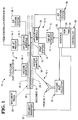
- Fig. 1 is a schematic diagram showing a terminal 10, like an encoder, for example, in which this invention may be incorporated.
- This invention relates to an air system 12 for protecting an ink jet head in an ink jet printer 14, shown only schematically in Fig. 1.
- the air system 12 includes a cleaning means 12-1 for cleaning dust particles from the front side of a document 16 and air flow providing means 12-2 for directing a curtain of air between the document 16 to be printed upon and the ink jet printer 14 at a print station designated generally as 18.
- An air system 13, similar to air system 12, may be used for cleaning the rear side of the document 16.
- the terminal 10 (Fig. 1) also includes a document track 20, having upstanding sides 20-1 and 20-2 which are shown in dashed outline to orient the reader.
- a document transport 22 is used to move the document 16 in a feeding direction in the direction of arrow 24 towards the print station 18, for example.
- the document transport 22 is coupled to a controller 26 via an interface 28, with the controller 26 conventionally controlling the movement of the document 16 in the terminal 10.
- Interface 28 represents a collection of conventional interfaces for coupling the controller 26 to the various elements in the terminal 10.
- the controller 26 has a ROM 30 and a RAM 32 in which software for controlling the operation of the terminal 10 may reside.
- the dust particles (which are mostly paper dust particles) are removed from the document 16 by the cleaning means 12-1 which includes a dust collector 36, preferably a cyclone dust collector, to collect the dust which is removed from the documents 16.
- a dust collector 36 preferably a cyclone dust collector
- cyclone dust collectors are used in saw mills and grain milling plants where the dust particles are quite large and there is adequate space for dust collectors.
- the cyclone dust collector 36 is compact and efficient; in fact it is so efficient that the air which is discharged therefrom can be discharged into the interior of the terminal 10 without concern for dust accumulating on the interior of the machine.
- the cleaning means 12-1 also includes a vacuum manifold 38, shown schematically in Fig. 1 and also shown in detail in Figs. 2 and 3.
- the vacuum manifold 38 is mounted upstream of the ink jet printer 14 so that the document 16 can be cleaned prior to reaching the print station 18.
- the vacuum manifold 38 includes a manifold 40 and an inlet plate 42.
- the vacuum manifold 38 is contoured, as shown at area 44, to distribute the vacuum across the height thereof, as shown in Fig. 2.
- the inlet plate 42 has a thickened area 46 thereon which protrudes through a recess in the document track 20 to enable the document 16 to brush thereagainst on its way to the print station 18.
- This thickened area 46 has a plurality of holes 48 therein to expose the document 16 to the vacuum from the cyclone dust collector 36.
- the inlet plate 42 also has a plurality of spaced parallel grooves 50 therein, with each of the grooves 50 communicating with one of the holes 48. These shallow grooves 50 in the surface of the inlet plate 42 insure that the document 16 does not seal off the supply of vacuum and that there is a continuous flow of air across the surface of the document 16. It is the air flow which sucks the paper dust, for example, from the surface of the document 16.
- the spaced parallel grooves 50 are positioned at an angle relative to the feeding direction (shown by arrow 52 in Fig.
- Suitable mounting holes 53 in the manifold 40 and the inlet plate 42 are used to secure the vacuum manifold 38 to the side 20-2 of the document track 20.
- the dusty air which is vacuumed from the surface of the document 16 by the vacuum manifold 38 is routed to the cyclone dust collector 36 by the flexible conduit 54 which is coupled to the vacuum manifold 38 and an inlet port on the cyclone dust collector 36, as shown best in Fig. 2.
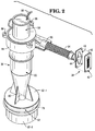
- the details of the cyclone dust collector 36 are shown in Figs. 2 and 4.
- the operation and construction of the cyclone dust collector 36 are as follows.
- the basic parts of the cyclone dust collector 36 are a blower 58, a body 60, and a collection cup 62.
- the body 60 includes a spiralling compartment 63 (Fig. 4) which receives the dusty air from the vacuum manifold 38 and causes the dusty air to move tangentially, as shown by the arrow 64. As the air moves tangentially as described, the dust particles which exist in the air are moved downwardly and outwardly towards the outer portions of the cyclone body 60.
- the air moving down in the cyclone dust collector 36 (shown by arrows 66) is separated from the air moving up in cyclone dust collector 36 (shown by arrow 68) by a tube 70.
- the air moving up in the tube 70 is clean air which has the dust particles removed and collected in collection cup 62.
- the blower 58 has an inlet port 72 which is aligned with the tube 70 so that the blower can exhaust air from the cyclone dust collector 36 and discharge it to the atmosphere via a discharge port 74.
- a resilient seal 76 positioned between the blower 58 and the spiralling compartment 63 (Fig. 4), is used to provide a seal between these two elements.
- the collection cup 62 has a lid portion 62-1 and a detachable cup portion 62-2 to enable the cup portion 62-2 to be removed to enable the collection cup 62 to be emptied of the dust contained therein.
- a resilient seal 78 shown only diagrammatically in Fig. 2, is used to provide a seal between the lid portion 62-1 and the cup portion 62-2.
- the lid portion 62-1 has an opening 80 in the center thereof to enable the dust particles and dust laden air to enter the collection cup 62.
- the blower 58 When the air enters the collection cup 62, the air tends to lose its velocity due to the increased volume of the collection cup 62 itself, and the direction of the air travel becomes more random. The dust particles actually collect on the bottom of the collection cup 62 rather than on the sides thereof. The dust-free air is then drawn up through the center tube 70 by the blower 58.
- the blower 58 fits inside the walls 82 and 84 (Fig. 4) of the cyclone dust collector 36.
- An apertured plate 79 (shown only partially in Fig. 4) and fasteners 81 are used to secure the blower 58 to the cyclone dust collector 36 via threaded mounting holes 86.
- the blower 58 has connection wires 88 which couple it to the controller 26 to be controlled thereby.
- the cyclone dust collector 36 offers several advantages over conventional filter separation of dust particles. First, filters slowly lose their efficiency as they become clogged with dust. In order to detect that a filter needs to be changed, one of the ways of performing this function is to use a detector which measures the pressure drop across the filter. This requires a pressure sensor and some sort of calibration scheme which are both costly and difficult to implement. Secondly, the cost of the filter itself and the environmental impact of the filter can be avoided when using the cyclone dust collector 36. In the embodiment described, cyclone dust collector 36, including the collection cup 62, is made of transparent plastic material to determine when the collection cup 62 needs to be emptied of the dust collected therein.
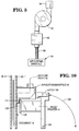
- the air flow producing means 12-2 is shown in Fig. 5, and it includes the air curtain manifold 34, a regulator 88 which is coupled to the air curtain manifold 34 by a conduit 90, a blower 92, and a filter 94.
- the conduit 90, regulator 88, blower 92, and the filter 94 are part of an air curtain system 96, shown only diagrammatically in Fig. 1.
- the function of the air flow producing means 12-2 is to provide a curtain of air between the ink jet printer 14 and the document 16 to be printed upon so as to direct dust particles away from the ink jet printer 14. It would seem, initially, that a curtain of air between the document 16 and the ink jet printer 14 would interfere with the ink droplets being directed at the document 16. However, when this air curtain was tried, it proved to be very effective in preventing the nozzles of the ink jet printer from being blocked. The cleaning maintenance was reduced from being required every 15 minutes to being required once during eight hours of operation.
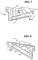
- the air curtain manifold 34 is shown in Figs. 6, 7, 8, and 9.
- the air curtain manifold 34 is positioned in a recess 98 in the side 20-1 of the document track 20, as shown in Fig. 6, and it is secured to the side 20-1 by suitable fasteners 99.
- the air curtain manifold 34 has a first chamber 102 having an inlet connector 104 to which the flexible conduit 90 (Fig. 5) is connected to supply air under pressure thereto.
- the air from the first chamber 102 communicates with a distributor or a second chamber 106 which distributes the air along the length of the air curtain manifold 34, which length is indicated by double arrow 108, as shown in Fig. 9.
- a planar control member 110 which is generally "U"-shaped, is secured to one side of the air curtain manifold 34 by fasteners 112, as shown in Fig. 9.
- the control member 110 has an area 114 of reduced thickness to enable the flow of air (shown by arrows 116) from the second chamber 106 to flow downwardly over the face of the ink jet printer 14. In doing so, the flow of air moves any dust particles away from the ink jet printer 14.
- the area 114 of reduced thickness, relative to the control member 110 provides an air curtain which is about 0.45 mm thick in the embodiment described.
- the ink jet printer 14 is shown in more detail in Fig. 10.
- This printer 14 may be mounted, conventionally, on a pivot member 120 to enable the printer 14 to be pivoted along the arc 122 away from the side 20-1 of the document track 20 to enable the printer 14 to be cleaned.
- a conventional latch 124 is used to detachably secure the ink jet printer 14 in the position shown in Fig. 10.
- the ink jet printer 14 has individual orifices or jets 126 which are mounted in a support member 128 Fig. 10.
- the support member 128 is mounted at an angle of about 19.5 degrees relative to the bottom of the document track 20, as shown by double arrow 130 in Fig. 6. In the embodiment described, the height of the characters printed by the ink jet printer 14 is 3mm.
- the printing which can be effected by the printer 14 is about 16 mm high and includes four lines of printing.
- the member 128 (Fig. 10) in which the jets 126 are located, should be kept as close to the document 16 as possible.
- the member 128 fits against the back side of the planar control surface or area 114(Fig. 10) in the side 20-1 of the document track 20. It was found from experimentation, that the frontal plane of the member 128 should preferably be located within one and one half millimeters from the document 16 itself.
- the side 20-1 of the document track 20 has a slot 100 therein to enable the ink from the jets 126 to reach the document 16.
- the slot 100 is longer than the length between the outermost jets 126; this dimension was arrived at after some experimentation.
- the slot 100 was just as long as the distance between the outermost jets 126, there were currents, like "eddy" currents, which were created at the extreme ends of the slot 100, especially the downstream end, and these currents caused scattered dots from the ink jet printer 14. It was found that a distance of about 6.35 mm between the outermost jets 126 and the associated ends of the slot 100 minimized this disturbance.
- the regulator 88 shown in Fig. 5 is set to provide a pressure of 25.4 mm of water at the regulator itself and to provide a pressure of 12.7 mm of water at the second chamber 106 (Fig. 8) of the air curtain manifold 34 in the embodiment described.
- the flow of air coming from the air curtain manifold 34 was effective in blowing any dust particles entering the slot 100, downwardly, and away from jets 126 of the ink jet printer 14 and not affect the path of the droplets of ink impacting against the document 16 during the printing process.
- the air pressure was increased to the point at which it began to affect the location of the droplets of ink, and thereafter, the pressure was lessened until a maximum air flow was obtained without affecting the displacement of characters printed by the ink jet printer 14.
- the ink jet printer 14 is shown in a position to print on the front of the document 16, printing may also be effected on the back of the document.
- endorsement of checks is effected on the rear of a check
- the endorsement of checks is effected on the front of the check.
- the air system 12 which has been described, can be repeated for printing or endorsing data on the rear of the document 16, as viewed in Fig. 1.
- the air system 13 is identical to the air system 12 already described. Consequently, those elements which are the same as the corresponding elements in the air system 12 will be given the same basic number; however, those in air system 13 will be given a dash (-) number.
- the vacuum manifold in air system 13 is designated as 38-1.
- the air system 13 also includes the ink jet printer 14-1, the air curtain manifold 34-1 and the air curtain system 96-1, with these elements having the same operation as their corresponding elements in air system 12.
- the air flow form the air curtain manifold 34 is in a downward direction, as shown in Fig. 6, the air flow could be directed to a side or upwardly if space considerations warranted it.
Abstract
Description
- This invention relates to a printing system including an ink jet printer.
- When an ink jet printer is used to print on documents which carry dust, the printing which results may not be as clear as it could be, and, because of the dust, the nozzles of the print head may become clogged and require frequent cleaning. In one prior art system, the nozzles in an ink jet head had to be cleaned every 15 minutes.
- In ink jet printing, as a document passes the print head, tiny droplets of ink "fly" through the air and land on the document surface to be printed upon. By controlling the sequence of nozzles which are activated, it is possible to form dot matrix characters on the passing document.
- The diameters of the nozzles on the print head are smaller than the diameter of a human hair, and as such, they are susceptible to blockage by dust, such as paper dust particles from the passing documents. When one or more paper dust particles block a nozzle, the ink droplets from that nozzle are either deflected or blocked entirely. This results in poor print quality, with the affected characters having deflected or missing dots.
- The offending dust particles can generally be removed by wiping the surface of the ink jet head with a "clean room quality" dust free cloth. Occasionally, however, it is necessary to pressurize the ink supply and force some ink through the nozzles in order to "purge" the dust particles from the nozzle. This operation is commonly referred to as a "reprime" operation. Both of these wiping and priming operations are nuisances, and they require the operator of the machine to stop it and to perform a number of maintenance operations.
- An object of this invention is to provide a printing system for reducing the likelihood of nozzle blockage in an ink jet printer which prints on documents liable to carry dust.
- Thus, according to the invention there is provided a printing system including a document track, an ink jet printer located adjacent said track, and feeding means for feeding a document along said track with a surface of said document in printing relation with said ink jet printer, characterized by an air system for producing at least one air flow adjacent said surface of said document, said air flow serving to inhibit the possibility of dust particles present on said surface when said document is approaching said air system from reaching the nozzles of said ink jet printer.
- The air system of a printing system in accordance with the invention may include cleaning means positioned upstream with respect to said ink jet printer and arranged to generate an air flow across said surface of the document for the purpose of removing dust particles from said surface, said cleaning means including collector means for collecting dust particles removed from said surface. In addition to, or in place of, said cleaning means, said air system may include air flow producing means arranged to direct a flow of air between said surface of the document and the nozzles of said ink jet printer for the purpose of directing dust particles away from said ink jet printer.
- One embodiment of the invention will now be described, by way of example, with reference to the accompanying drawings, in which:-
- Fig. 1 is a schematic diagram, in plan view, of a business terminal, like an endorser, for example, in which the air system made according to this invention may be incorporated. The long top edge of a document is shown in a document track associated with the terminal.
- Fig. 2 is an isometric view of a cleaning means including a cyclone dust collector for cleaning documents before they arrive at a print station where an ink jet printer is located.
- Fig. 3 is an enlarged view of a vacuum manifold, shown only schematically in Fig. 1.
- Fig. 4 is an exploded view of a portion of the cyclone dust collector shown in Fig. 2.
- Fig. 5 is a schematic diagram of an air flow producing means for providing a curtain of air between the document and the ink jet printer shown in fig. 1.
- Fig. 6 is a side view, taken from the direction of arrow A of Fig. 1 to show details of an air curtain manifold shown in Fig. 1.
- Fig. 7 is an isometric view of the air curtain manifold shown in Fig. 6, with the view taken from the general direction of the arrow B shown in Fig. 6.
- Fig. 8 is an isometric view of the air curtain manifold, with this view being taken from the direction of arrow C of Fig. 7.
- Fig. 9 is a view similar to Fig. 8, showing in exploded view, another element included in the air curtain manifold.
- Fig. 10 is a general, cross-sectional view, taken along the line 10-10 of Fig. 6, to show the ink jet printer and the air curtain manifold.
- Fig. 1 is a schematic diagram showing a
terminal 10, like an encoder, for example, in which this invention may be incorporated. This invention relates to anair system 12 for protecting an ink jet head in anink jet printer 14, shown only schematically in Fig. 1. Theair system 12 includes a cleaning means 12-1 for cleaning dust particles from the front side of adocument 16 and air flow providing means 12-2 for directing a curtain of air between thedocument 16 to be printed upon and theink jet printer 14 at a print station designated generally as 18. Anair system 13, similar toair system 12, may be used for cleaning the rear side of thedocument 16. - The terminal 10 (Fig. 1) also includes a
document track 20, having upstanding sides 20-1 and 20-2 which are shown in dashed outline to orient the reader. Adocument transport 22 is used to move thedocument 16 in a feeding direction in the direction ofarrow 24 towards theprint station 18, for example. Thedocument transport 22 is coupled to acontroller 26 via aninterface 28, with thecontroller 26 conventionally controlling the movement of thedocument 16 in theterminal 10.Interface 28 represents a collection of conventional interfaces for coupling thecontroller 26 to the various elements in theterminal 10. Thecontroller 26 has aROM 30 and aRAM 32 in which software for controlling the operation of theterminal 10 may reside. - The dust particles (which are mostly paper dust particles) are removed from the
document 16 by the cleaning means 12-1 which includes adust collector 36, preferably a cyclone dust collector, to collect the dust which is removed from thedocuments 16. Typically, cyclone dust collectors are used in saw mills and grain milling plants where the dust particles are quite large and there is adequate space for dust collectors. Thecyclone dust collector 36 is compact and efficient; in fact it is so efficient that the air which is discharged therefrom can be discharged into the interior of theterminal 10 without concern for dust accumulating on the interior of the machine. - The cleaning means 12-1 also includes a
vacuum manifold 38, shown schematically in Fig. 1 and also shown in detail in Figs. 2 and 3. Thevacuum manifold 38 is mounted upstream of theink jet printer 14 so that thedocument 16 can be cleaned prior to reaching theprint station 18. Thevacuum manifold 38 includes amanifold 40 and aninlet plate 42. Thevacuum manifold 38 is contoured, as shown atarea 44, to distribute the vacuum across the height thereof, as shown in Fig. 2. Theinlet plate 42 has a thickenedarea 46 thereon which protrudes through a recess in thedocument track 20 to enable thedocument 16 to brush thereagainst on its way to theprint station 18. This thickenedarea 46 has a plurality ofholes 48 therein to expose thedocument 16 to the vacuum from thecyclone dust collector 36. Theinlet plate 42 also has a plurality of spacedparallel grooves 50 therein, with each of thegrooves 50 communicating with one of theholes 48. Theseshallow grooves 50 in the surface of theinlet plate 42 insure that thedocument 16 does not seal off the supply of vacuum and that there is a continuous flow of air across the surface of thedocument 16. It is the air flow which sucks the paper dust, for example, from the surface of thedocument 16. The spacedparallel grooves 50 are positioned at an angle relative to the feeding direction (shown byarrow 52 in Fig. 3) of thedocument 16 so as to increase the area of coverage of theholes 48 and thegrooves 50 on thedocument 16.Suitable mounting holes 53 in themanifold 40 and theinlet plate 42 are used to secure thevacuum manifold 38 to the side 20-2 of thedocument track 20. - The dusty air which is vacuumed from the surface of the
document 16 by thevacuum manifold 38 is routed to thecyclone dust collector 36 by theflexible conduit 54 which is coupled to thevacuum manifold 38 and an inlet port on thecyclone dust collector 36, as shown best in Fig. 2. The details of thecyclone dust collector 36 are shown in Figs. 2 and 4. - The operation and construction of the
cyclone dust collector 36 are as follows. The basic parts of thecyclone dust collector 36 are ablower 58, abody 60, and acollection cup 62. Thebody 60 includes a spiralling compartment 63 (Fig. 4) which receives the dusty air from thevacuum manifold 38 and causes the dusty air to move tangentially, as shown by thearrow 64. As the air moves tangentially as described, the dust particles which exist in the air are moved downwardly and outwardly towards the outer portions of thecyclone body 60. At this point, the air moving down in the cyclone dust collector 36 (shown by arrows 66) is separated from the air moving up in cyclone dust collector 36 (shown by arrow 68) by atube 70. The air moving up in thetube 70 is clean air which has the dust particles removed and collected incollection cup 62. Theblower 58 has aninlet port 72 which is aligned with thetube 70 so that the blower can exhaust air from thecyclone dust collector 36 and discharge it to the atmosphere via adischarge port 74. Aresilient seal 76, positioned between theblower 58 and the spiralling compartment 63 (Fig. 4), is used to provide a seal between these two elements. - As the dust particles descend downwardly and outwardly in the
body 60 of the cyclone dust collector 36 (as viewed in Fig. 2), the dust particles settle in thecollection cup 62. Thecollection cup 62 has a lid portion 62-1 and a detachable cup portion 62-2 to enable the cup portion 62-2 to be removed to enable thecollection cup 62 to be emptied of the dust contained therein. Aresilient seal 78, shown only diagrammatically in Fig. 2, is used to provide a seal between the lid portion 62-1 and the cup portion 62-2. The lid portion 62-1 has anopening 80 in the center thereof to enable the dust particles and dust laden air to enter thecollection cup 62. When the air enters thecollection cup 62, the air tends to lose its velocity due to the increased volume of thecollection cup 62 itself, and the direction of the air travel becomes more random. The dust particles actually collect on the bottom of thecollection cup 62 rather than on the sides thereof. The dust-free air is then drawn up through thecenter tube 70 by theblower 58. Theblower 58 fits inside thewalls 82 and 84 (Fig. 4) of thecyclone dust collector 36. An apertured plate 79 (shown only partially in Fig. 4) andfasteners 81 are used to secure theblower 58 to thecyclone dust collector 36 via threaded mounting holes 86. Theblower 58 hasconnection wires 88 which couple it to thecontroller 26 to be controlled thereby. - The
cyclone dust collector 36 offers several advantages over conventional filter separation of dust particles. First, filters slowly lose their efficiency as they become clogged with dust. In order to detect that a filter needs to be changed, one of the ways of performing this function is to use a detector which measures the pressure drop across the filter. This requires a pressure sensor and some sort of calibration scheme which are both costly and difficult to implement. Secondly, the cost of the filter itself and the environmental impact of the filter can be avoided when using thecyclone dust collector 36. In the embodiment described,cyclone dust collector 36, including thecollection cup 62, is made of transparent plastic material to determine when thecollection cup 62 needs to be emptied of the dust collected therein. - The air flow producing means 12-2 is shown in Fig. 5, and it includes the
air curtain manifold 34, aregulator 88 which is coupled to theair curtain manifold 34 by aconduit 90, ablower 92, and afilter 94. Theconduit 90,regulator 88,blower 92, and thefilter 94 are part of anair curtain system 96, shown only diagrammatically in Fig. 1. The function of the air flow producing means 12-2 is to provide a curtain of air between theink jet printer 14 and thedocument 16 to be printed upon so as to direct dust particles away from theink jet printer 14. It would seem, initially, that a curtain of air between thedocument 16 and theink jet printer 14 would interfere with the ink droplets being directed at thedocument 16. However, when this air curtain was tried, it proved to be very effective in preventing the nozzles of the ink jet printer from being blocked. The cleaning maintenance was reduced from being required every 15 minutes to being required once during eight hours of operation. - The
air curtain manifold 34 is shown in Figs. 6, 7, 8, and 9. Theair curtain manifold 34 is positioned in arecess 98 in the side 20-1 of thedocument track 20, as shown in Fig. 6, and it is secured to the side 20-1 bysuitable fasteners 99. There is a suitableelongated slot 100 in the side 20-1 of thedocument track 20 to enable theink jet printer 14 to print on thedocument 16. - The
air curtain manifold 34 has afirst chamber 102 having aninlet connector 104 to which the flexible conduit 90 (Fig. 5) is connected to supply air under pressure thereto. The air from thefirst chamber 102 communicates with a distributor or asecond chamber 106 which distributes the air along the length of theair curtain manifold 34, which length is indicated bydouble arrow 108, as shown in Fig. 9. Aplanar control member 110, which is generally "U"-shaped, is secured to one side of theair curtain manifold 34 byfasteners 112, as shown in Fig. 9. Thecontrol member 110 has anarea 114 of reduced thickness to enable the flow of air (shown by arrows 116) from thesecond chamber 106 to flow downwardly over the face of theink jet printer 14. In doing so, the flow of air moves any dust particles away from theink jet printer 14. Thearea 114 of reduced thickness, relative to thecontrol member 110, provides an air curtain which is about 0.45 mm thick in the embodiment described. - The
ink jet printer 14 is shown in more detail in Fig. 10. Thisprinter 14 may be mounted, conventionally, on apivot member 120 to enable theprinter 14 to be pivoted along thearc 122 away from the side 20-1 of thedocument track 20 to enable theprinter 14 to be cleaned. Aconventional latch 124 is used to detachably secure theink jet printer 14 in the position shown in Fig. 10. Theink jet printer 14 has individual orifices orjets 126 which are mounted in asupport member 128 Fig. 10. Thesupport member 128 is mounted at an angle of about 19.5 degrees relative to the bottom of thedocument track 20, as shown bydouble arrow 130 in Fig. 6. In the embodiment described, the height of the characters printed by theink jet printer 14 is 3mm. By tilting the orifices orjets 126 at the angle of 19.5 degrees, the printing which can be effected by theprinter 14 is about 16 mm high and includes four lines of printing. - The member 128 (Fig. 10) in which the
jets 126 are located, should be kept as close to thedocument 16 as possible. Themember 128 fits against the back side of the planar control surface or area 114(Fig. 10) in the side 20-1 of thedocument track 20. It was found from experimentation, that the frontal plane of themember 128 should preferably be located within one and one half millimeters from thedocument 16 itself. - As previously stated, the side 20-1 of the
document track 20 has aslot 100 therein to enable the ink from thejets 126 to reach thedocument 16. Theslot 100 is longer than the length between theoutermost jets 126; this dimension was arrived at after some experimentation. When theslot 100 was just as long as the distance between theoutermost jets 126, there were currents, like "eddy" currents, which were created at the extreme ends of theslot 100, especially the downstream end, and these currents caused scattered dots from theink jet printer 14. It was found that a distance of about 6.35 mm between theoutermost jets 126 and the associated ends of theslot 100 minimized this disturbance. - The
regulator 88 shown in Fig. 5 is set to provide a pressure of 25.4 mm of water at the regulator itself and to provide a pressure of 12.7 mm of water at the second chamber 106 (Fig. 8) of theair curtain manifold 34 in the embodiment described. With these pressures, the flow of air coming from theair curtain manifold 34 was effective in blowing any dust particles entering theslot 100, downwardly, and away fromjets 126 of theink jet printer 14 and not affect the path of the droplets of ink impacting against thedocument 16 during the printing process. To arrive at the pressure indicated, the air pressure was increased to the point at which it began to affect the location of the droplets of ink, and thereafter, the pressure was lessened until a maximum air flow was obtained without affecting the displacement of characters printed by theink jet printer 14. - While the
ink jet printer 14 is shown in a position to print on the front of thedocument 16, printing may also be effected on the back of the document. In North America, endorsement of checks is effected on the rear of a check, while in many European countries, the endorsement of checks is effected on the front of the check. Thus, theair system 12, which has been described, can be repeated for printing or endorsing data on the rear of thedocument 16, as viewed in Fig. 1. In this regard, theair system 13 is identical to theair system 12 already described. Consequently, those elements which are the same as the corresponding elements in theair system 12 will be given the same basic number; however, those inair system 13 will be given a dash (-) number. For example, the vacuum manifold inair system 13 is designated as 38-1. Correspondingly, theair system 13 also includes the ink jet printer 14-1, the air curtain manifold 34-1 and the air curtain system 96-1, with these elements having the same operation as their corresponding elements inair system 12. - While the air flow form the
air curtain manifold 34 is in a downward direction, as shown in Fig. 6, the air flow could be directed to a side or upwardly if space considerations warranted it.
Claims (10)
- A printing system including a document track, an ink jet printer located adjacent said track, and feeding means for feeding a document along said track with a surface of said document in printing relation with said ink jet printer, characterized by an air system (12) for producing at least one air flow adjacent said surface of said document (16), said air flow serving to inhibit the possibility of dust particles present on said surface when said document (16) is approaching said air system (12) from reaching the nozzles (126) of said ink jet printer (14).
- A printing system according to claim 1, characterized in that said air system (12) includes cleaning means (12-1) positioned upstream with respect to said ink jet printer (14) and arranged to generate an air flow across said surface of said document for the purpose of removing dust particles from said surface, said cleaning means including collector means (36) for collecting dust particles removed from said surface.
- A system according to claim 2, characterized in that said collecting means (36) is a cyclone dust collector.
- A system according to either claim 2 or 3, characterized in that said cleaning means (12-1) includes a vacuum manifold (38) having a vacuum inlet plate (42) facing the surface of a document (16) to be cleaned from dust, with said inlet plate (42) having a plurality of substantially parallel grooves (50) therein, and openings (48) in said grooves (50) to permit air and dust particles to pass between said inlet plate (42) and said surface of the document (16).
- A system according to claim 4, characterized in that said grooves (50) are positioned at an angle relative to the direction of feeding of the document (16).
- A printing system according to any one of the preceding claims, characterized by air flow producing means (12-2) arranged to direct a flow of air between said surface of said document (16) and the nozzles (126) of said ink jet printer (14) for the purpose of directing dust particles away from said ink jet printer (14).
- A system according to claim 6, characterized in that said air flow producing means (12-2) includes an air manifold (34) positioned adjacent said ink jet printer (14), and an air regulator (88) for maintaining air flow through said air manifold (34) strong enough to direct dust particles away form said ink jet printer (14), yet gentle enough so that ink droplets from said ink jet printer (14) are not significantly deflected from their paths.
- A system according to claim 7, characterized in that said air manifold (34) has a first chamber (102) for receiving air from said air regulator (88), and a second chamber (106) communicating with said first chamber (102) for distributing air to provide said flow of air between said surface of the document (16) and said nozzles (126).
- A system according to either claim 7 or 8, characterized in that said document track (20) has a side wall (20-1) having a recess (98) therein, said air manifold (34) being located in said recess (98).
- A system according to claim 9, characterized by an elongated slot (100) in the side wall (20-1) of said document track (20) within said recess (98), to allow the ink droplets from said ink jet printer (14) to search said document (16), wherein said slot (100) is longer than the distance between the outermost nozzles (126).
Applications Claiming Priority (2)
| Application Number | Priority Date | Filing Date | Title |
|---|---|---|---|
| US07/993,589 US5519420A (en) | 1992-12-21 | 1992-12-21 | Air system to protect ink jet head |
| US993589 | 2001-11-06 |
Publications (3)
| Publication Number | Publication Date |
|---|---|
| EP0604029A2 true EP0604029A2 (en) | 1994-06-29 |
| EP0604029A3 EP0604029A3 (en) | 1994-12-14 |
| EP0604029B1 EP0604029B1 (en) | 1998-04-22 |
Family
ID=25539732
Family Applications (1)
| Application Number | Title | Priority Date | Filing Date |
|---|---|---|---|
| EP93309483A Expired - Lifetime EP0604029B1 (en) | 1992-12-21 | 1993-11-29 | Printing system including an ink jet printer |
Country Status (7)
| Country | Link |
|---|---|
| US (1) | US5519420A (en) |
| EP (1) | EP0604029B1 (en) |
| AU (1) | AU667589B2 (en) |
| CA (1) | CA2103184C (en) |
| ES (1) | ES2115025T3 (en) |
| NZ (1) | NZ250320A (en) |
| ZA (1) | ZA938958B (en) |
Cited By (23)
| Publication number | Priority date | Publication date | Assignee | Title |
|---|---|---|---|---|
| DE19601256C1 (en) * | 1996-01-16 | 1997-04-10 | Aeg Electrocom Gmbh | Guide system for printing postmarks on letter type items |
| EP0790129A2 (en) * | 1996-02-13 | 1997-08-20 | Canon Kabushiki Kaisha | Liquid ejection apparatus, head unit and ink-jet cartridge |
| WO2001089847A1 (en) * | 2000-05-23 | 2001-11-29 | Silverbrook Research Pty. Ltd. | Air supply arrangement for a printer |
| WO2002036347A2 (en) | 2000-10-31 | 2002-05-10 | Zipher Limited | Printing apparatus |
| EP1301349A1 (en) * | 2000-06-30 | 2003-04-16 | Silverbrook Research Pty. Limited | A print engine including an air pump |
| EP1273449A3 (en) * | 2001-07-06 | 2003-08-13 | Illinois Tool Works Inc. | Low debris fluid jetting system |
| AU2002214848B2 (en) * | 2000-12-21 | 2004-04-01 | Zamtec Limited | Nozzle flood isolation for ink jet printhead |
| US6796731B2 (en) | 2000-05-23 | 2004-09-28 | Silverbrook Research Pty Ltd | Laminated ink distribution assembly for a printer |
| AU2004233535B2 (en) * | 2000-05-24 | 2005-02-24 | Zamtec Limited | A printer including a printhead having positive air pressure zone |
| AU2004202888B2 (en) * | 2000-12-21 | 2005-04-28 | Zamtec Limited | Nozzle Containment Formation For Ink Jet Printhead |
| US6918647B2 (en) | 2001-09-04 | 2005-07-19 | Silverbrook Research Pty Ltd | Inkjet printhead assembly having a rotary platen assembly |
| US6923866B2 (en) | 2003-06-13 | 2005-08-02 | Spectra, Inc. | Apparatus for depositing droplets |
| AU2004203192B2 (en) * | 2000-06-30 | 2005-10-06 | Zamtec Limited | A motor arrangement for a print engine |
| US6984080B2 (en) | 2000-05-23 | 2006-01-10 | Silverbrook Research Pty Ltd | Laminated distribution structure |
| US6988840B2 (en) | 2000-05-23 | 2006-01-24 | Silverbrook Research Pty Ltd | Printhead chassis assembly |
| US6997539B2 (en) | 2003-06-13 | 2006-02-14 | Dimatix, Inc. | Apparatus for depositing droplets |
| AU2005202040B2 (en) * | 2000-05-24 | 2006-08-17 | Zamtec Limited | Reducing nozzle buildup by providing positive air pressure zone |
| CN1328054C (en) * | 2001-02-06 | 2007-07-25 | 西尔弗布鲁克研究有限公司 | Flooded nozzle detection |
| US7431281B2 (en) | 2001-02-07 | 2008-10-07 | Silverbrook Research Pty Ltd | Method of separating a sheet of print media from a stack of sheets |
| SG152033A1 (en) * | 2000-05-24 | 2009-05-29 | Silverbrook Res Pty Ltd | Printhead with air supply arrangement. |
| US7824021B2 (en) | 2000-05-23 | 2010-11-02 | Silverbrook Research Pty Ltd | Printhead assembly with printheads within a laminated stack which, in turn is within an ink distribution structure |
| EP2311640A1 (en) * | 2004-03-19 | 2011-04-20 | Zipher Limited | Liquid supply system |
| CN104169095A (en) * | 2012-03-30 | 2014-11-26 | 惠普发展公司,有限责任合伙企业 | Recirculate and filter air to form air barrier in image forming apparatus |
Families Citing this family (17)
| Publication number | Priority date | Publication date | Assignee | Title |
|---|---|---|---|---|
| US6390618B1 (en) * | 2000-01-07 | 2002-05-21 | Hewlett-Packard Company | Method and apparatus for ink-jet print zone drying |
| US6281912B1 (en) | 2000-05-23 | 2001-08-28 | Silverbrook Research Pty Ltd | Air supply arrangement for a printer |
| CN100352653C (en) * | 2000-05-24 | 2007-12-05 | 西尔弗布鲁克研究有限公司 | Printing head with air supply device |
| SG155029A1 (en) * | 2000-06-30 | 2009-09-30 | Silverbrook Res Pty Ltd | A motor arrangement for a print engine |
| AUPR224000A0 (en) * | 2000-12-21 | 2001-01-25 | Silverbrook Research Pty. Ltd. | An apparatus (mj28) |
| US6890053B2 (en) * | 2003-03-28 | 2005-05-10 | Illinois Tool Works, Inc. | Positive air system for inkjet print head |
| US7207671B2 (en) * | 2004-05-05 | 2007-04-24 | Eastman Kodak Company | HEPA filter printhead protection |
| US7520588B2 (en) * | 2005-12-23 | 2009-04-21 | Xerox Corp | Apparatus for reducing ink jet contamination |
| JP4997229B2 (en) * | 2006-05-01 | 2012-08-08 | 株式会社アルバック | Printing device |
| US7571996B2 (en) * | 2006-08-10 | 2009-08-11 | Xerox Corporation | Apparatus for reducing particulate in an ink jet printer |
| US20110025760A1 (en) | 2009-07-31 | 2011-02-03 | Silverbrook Research Pty Ltd | Printing system with printheads supplied by multiple ink conduits connected by a bypass line |
| US20110277303A1 (en) | 2010-05-17 | 2011-11-17 | Silverbrook Research Pty Ltd | Method of assembling printhead fluid distribution coupling |
| US8602543B2 (en) | 2010-05-17 | 2013-12-10 | Zamtec Limited | Printing system having valved ink and gas distribution for printhead |
| US9823169B1 (en) | 2013-04-22 | 2017-11-21 | The United States Of America As Represented By The Secretary Of The Department Of The Interior | Cyclonic fugitive dust sampler |
| US9039812B2 (en) * | 2013-06-28 | 2015-05-26 | Hewlett-Packard Development Company, L.P. | Exhaust substance removal |
| US10099496B2 (en) | 2014-06-25 | 2018-10-16 | Hewlett-Packard Development Company, L.P. | Inhibiting air flow |
| US9827792B2 (en) * | 2015-03-06 | 2017-11-28 | Kyocera Document Solutions Inc. | Inkjet recording apparatus |
Citations (5)
| Publication number | Priority date | Publication date | Assignee | Title |
|---|---|---|---|---|
| US4411706A (en) * | 1981-06-25 | 1983-10-25 | Burroughs Corporation | Method and apparatus for eliminating dust from ink jet printers |
| US4591869A (en) * | 1985-04-12 | 1986-05-27 | Eastman Kodak Company | Ink jet printing apparatus and method providing an induced, clean-air region |
| EP0371828A1 (en) * | 1988-11-29 | 1990-06-06 | Bull S.A. | Apparatus for separating and recovering solid toner particles transported by a gas flow |
| JPH03234539A (en) * | 1990-02-09 | 1991-10-18 | Canon Inc | Ink jet recorder |
| JPH0439053A (en) * | 1990-06-04 | 1992-02-10 | Seiko Epson Corp | Production of nozzle |
Family Cites Families (5)
| Publication number | Priority date | Publication date | Assignee | Title |
|---|---|---|---|---|
| US3854399A (en) * | 1972-12-29 | 1974-12-17 | Dick Co Ab | Method and means for operating an ink jet printer without splatter |
| US4361845A (en) * | 1981-03-16 | 1982-11-30 | International Business Machines Corporation | Device for preventing the contamination of ink jet components |
| JPS61164838A (en) * | 1985-01-18 | 1986-07-25 | Nec Corp | Ink jet head |
| JPS62220388A (en) * | 1986-03-20 | 1987-09-28 | Tokyo Electric Co Ltd | Method and apparatus for recording image |
| US4861178A (en) * | 1988-07-06 | 1989-08-29 | Reed Patrick G | Vacuum system for computer printers |
-
1992
- 1992-12-21 US US07/993,589 patent/US5519420A/en not_active Expired - Lifetime
-
1993
- 1993-11-16 CA CA002103184A patent/CA2103184C/en not_active Expired - Fee Related
- 1993-11-29 AU AU52021/93A patent/AU667589B2/en not_active Ceased
- 1993-11-29 EP EP93309483A patent/EP0604029B1/en not_active Expired - Lifetime
- 1993-11-29 ES ES93309483T patent/ES2115025T3/en not_active Expired - Lifetime
- 1993-11-30 ZA ZA938958A patent/ZA938958B/en unknown
- 1993-11-30 NZ NZ250320A patent/NZ250320A/en unknown
Patent Citations (5)
| Publication number | Priority date | Publication date | Assignee | Title |
|---|---|---|---|---|
| US4411706A (en) * | 1981-06-25 | 1983-10-25 | Burroughs Corporation | Method and apparatus for eliminating dust from ink jet printers |
| US4591869A (en) * | 1985-04-12 | 1986-05-27 | Eastman Kodak Company | Ink jet printing apparatus and method providing an induced, clean-air region |
| EP0371828A1 (en) * | 1988-11-29 | 1990-06-06 | Bull S.A. | Apparatus for separating and recovering solid toner particles transported by a gas flow |
| JPH03234539A (en) * | 1990-02-09 | 1991-10-18 | Canon Inc | Ink jet recorder |
| JPH0439053A (en) * | 1990-06-04 | 1992-02-10 | Seiko Epson Corp | Production of nozzle |
Non-Patent Citations (2)
| Title |
|---|
| PATENT ABSTRACTS OF JAPAN vol. 16, no. 16 (M-1200) (5059) 16 January 1992 & JP-A-03 234 539 (CANON INC) 18 October 1991 * |
| PATENT ABSTRACTS OF JAPAN vol. 16, no. 214 (M-1251) (5257) 20 May 1992 & JP-A-04 039 053 (SEIKO EPSON CORP.) 10 February 1992 * |
Cited By (61)
| Publication number | Priority date | Publication date | Assignee | Title |
|---|---|---|---|---|
| DE19601256C1 (en) * | 1996-01-16 | 1997-04-10 | Aeg Electrocom Gmbh | Guide system for printing postmarks on letter type items |
| WO1997026138A1 (en) * | 1996-01-16 | 1997-07-24 | Siemens Aktiengesellschaft | Device for guiding moving letters and parcels |
| US6328441B1 (en) | 1996-01-16 | 2001-12-11 | Siemens Aktiengesellschaft | Device for guiding moving letters and parcels |
| EP0790129A2 (en) * | 1996-02-13 | 1997-08-20 | Canon Kabushiki Kaisha | Liquid ejection apparatus, head unit and ink-jet cartridge |
| EP0790129A3 (en) * | 1996-02-13 | 1998-10-14 | Canon Kabushiki Kaisha | Liquid ejection apparatus, head unit and ink-jet cartridge |
| US6883895B2 (en) | 1996-02-13 | 2005-04-26 | Canon Kabushiki Kaisha | Liquid ejection apparatus, head unit and ink-jet cartridge |
| US7931358B2 (en) | 2000-05-23 | 2011-04-26 | Silverbrook Research Pty Ltd | Pagewidth printhead assembly with top-fed ink ducts |
| US7364377B2 (en) | 2000-05-23 | 2008-04-29 | Silverbrook Research Pty Ltd | Print engine assembly with an elongate converging ink distribution assembly |
| US7114868B2 (en) | 2000-05-23 | 2006-10-03 | Silverbrook Research Pty Ltd | Inkjet printing assembly with multi-purpose platen assembly |
| US7841710B2 (en) | 2000-05-23 | 2010-11-30 | Silverbrook Research Pty Ltd | Printhead assembly with a pressurized air supply for an inkjet printer |
| US7824021B2 (en) | 2000-05-23 | 2010-11-02 | Silverbrook Research Pty Ltd | Printhead assembly with printheads within a laminated stack which, in turn is within an ink distribution structure |
| US7748833B2 (en) | 2000-05-23 | 2010-07-06 | Silverbrook Research Pty Ltd | Ink distribution structure with a laminated ink supply stack for an inkjet printer |
| US7740338B2 (en) | 2000-05-23 | 2010-06-22 | Silverbrook Research Pty Ltd | Printhead assembly having a pressurised air supply |
| US7658467B2 (en) | 2000-05-23 | 2010-02-09 | Silverbrook Research Pty Ltd | Printhead assembly laminated ink distribution stack |
| US6796731B2 (en) | 2000-05-23 | 2004-09-28 | Silverbrook Research Pty Ltd | Laminated ink distribution assembly for a printer |
| US7467859B2 (en) | 2000-05-23 | 2008-12-23 | Silverbrook Research Pty Ltd | Pagewidth printhead assembly with ink distribution arrangement |
| US8075112B2 (en) | 2000-05-23 | 2011-12-13 | Silverbrook Research Pty Ltd | Printhead assembly with air cleaning arrangement |
| WO2001089847A1 (en) * | 2000-05-23 | 2001-11-29 | Silverbrook Research Pty. Ltd. | Air supply arrangement for a printer |
| US7425053B2 (en) | 2000-05-23 | 2008-09-16 | Silverbrook Research Pty Ltd | Printhead assembly with a laminated ink distribution assembly |
| US7980658B2 (en) | 2000-05-23 | 2011-07-19 | Silverbrook Research Pty Ltd | Rotatable platen |
| US7328994B2 (en) | 2000-05-23 | 2008-02-12 | Silverbrook Research Pty Ltd | Print engine assembly with slotted chassis |
| US7325986B2 (en) | 2000-05-23 | 2008-02-05 | Silverbrook Research Pty Ltd | Printhead assembly with stacked ink distribution sheets |
| US6984016B2 (en) | 2000-05-23 | 2006-01-10 | Silverbrook Research Pty. Ltd. | Self-cleaning inkjet printhead assembly |
| US6984080B2 (en) | 2000-05-23 | 2006-01-10 | Silverbrook Research Pty Ltd | Laminated distribution structure |
| US6988840B2 (en) | 2000-05-23 | 2006-01-24 | Silverbrook Research Pty Ltd | Printhead chassis assembly |
| US6994419B2 (en) | 2000-05-23 | 2006-02-07 | Silverbrook Research Pty Ltd | Multi-function printhead platen |
| US6997626B2 (en) | 2000-05-23 | 2006-02-14 | Silverbrook Research Pty Ltd | Ink and air distribution within a printer assembly |
| US7284817B2 (en) | 2000-05-23 | 2007-10-23 | Silverbrook Research Pty Ltd | Printer with a self-cleaning inkjet printhead assembly |
| US6997625B2 (en) | 2000-05-23 | 2006-02-14 | Silverbrook Research Pty Ltd | Ink distribution assembly |
| US7044577B2 (en) | 2000-05-23 | 2006-05-16 | Silverbrook Research Pty Ltd | Printer having a rotary platen assembly for supporting print media |
| US7192125B2 (en) | 2000-05-23 | 2007-03-20 | Silverbrook Research Pty Ltd | Ink jet printer that incorporates an ink distribution assembly |
| US7083258B2 (en) | 2000-05-23 | 2006-08-01 | Silverbrook Research Pty Ltd | Printhead assembly |
| AU2004233535B2 (en) * | 2000-05-24 | 2005-02-24 | Zamtec Limited | A printer including a printhead having positive air pressure zone |
| SG152033A1 (en) * | 2000-05-24 | 2009-05-29 | Silverbrook Res Pty Ltd | Printhead with air supply arrangement. |
| AU2000247330B2 (en) * | 2000-05-24 | 2004-05-06 | Zamtec Limited | Air supply arrangement for a printer |
| US7055930B1 (en) | 2000-05-24 | 2006-06-06 | Silverbrook Research Pty Ltd | Air supply arrangement for a printer |
| AU2004203509B2 (en) * | 2000-05-24 | 2004-09-23 | Zamtec Limited | Printhead with air supply arrangement |
| US7357475B2 (en) | 2000-05-24 | 2008-04-15 | Silverbrook Research Pty Ltd | Filtered air supply for nozzle guard |
| AU2005202040B2 (en) * | 2000-05-24 | 2006-08-17 | Zamtec Limited | Reducing nozzle buildup by providing positive air pressure zone |
| AU2004203192B2 (en) * | 2000-06-30 | 2005-10-06 | Zamtec Limited | A motor arrangement for a print engine |
| EP1301349A1 (en) * | 2000-06-30 | 2003-04-16 | Silverbrook Research Pty. Limited | A print engine including an air pump |
| EP1301349A4 (en) * | 2000-06-30 | 2004-09-29 | Silverbrook Res Pty Ltd | A print engine including an air pump |
| GB2370532A (en) * | 2000-10-31 | 2002-07-03 | Zipher Ltd | Printing apparatus with a print face of a purged printhead thereof cleaned by a curtain of air blown across the face of the printhead |
| GB2370532B (en) * | 2000-10-31 | 2004-06-23 | Zipher Ltd | Printing apparatus |
| EP1780023A2 (en) | 2000-10-31 | 2007-05-02 | Zipher Limited | Printing apparatus |
| US7419239B2 (en) | 2000-10-31 | 2008-09-02 | Zipher Limited | Printing apparatus |
| WO2002036347A2 (en) | 2000-10-31 | 2002-05-10 | Zipher Limited | Printing apparatus |
| US7600852B2 (en) | 2000-10-31 | 2009-10-13 | Zipher Limited | Printing apparatus |
| AU2004202888B2 (en) * | 2000-12-21 | 2005-04-28 | Zamtec Limited | Nozzle Containment Formation For Ink Jet Printhead |
| AU2002214848B2 (en) * | 2000-12-21 | 2004-04-01 | Zamtec Limited | Nozzle flood isolation for ink jet printhead |
| CN1328054C (en) * | 2001-02-06 | 2007-07-25 | 西尔弗布鲁克研究有限公司 | Flooded nozzle detection |
| US7431281B2 (en) | 2001-02-07 | 2008-10-07 | Silverbrook Research Pty Ltd | Method of separating a sheet of print media from a stack of sheets |
| EP1273449A3 (en) * | 2001-07-06 | 2003-08-13 | Illinois Tool Works Inc. | Low debris fluid jetting system |
| US6918647B2 (en) | 2001-09-04 | 2005-07-19 | Silverbrook Research Pty Ltd | Inkjet printhead assembly having a rotary platen assembly |
| US7178892B2 (en) | 2001-09-04 | 2007-02-20 | Silverbrook Res Pty Ltd | Printhead-to-platen variable spacing mechanism |
| US6923866B2 (en) | 2003-06-13 | 2005-08-02 | Spectra, Inc. | Apparatus for depositing droplets |
| US7326439B2 (en) | 2003-06-13 | 2008-02-05 | Fujifilm Dimatix, Inc. | Apparatus for depositing droplets |
| US6997539B2 (en) | 2003-06-13 | 2006-02-14 | Dimatix, Inc. | Apparatus for depositing droplets |
| EP2311640A1 (en) * | 2004-03-19 | 2011-04-20 | Zipher Limited | Liquid supply system |
| CN104169095A (en) * | 2012-03-30 | 2014-11-26 | 惠普发展公司,有限责任合伙企业 | Recirculate and filter air to form air barrier in image forming apparatus |
| US9409420B2 (en) | 2012-03-30 | 2016-08-09 | Hewlett-Packard Development Company, L.P. | Recirculate and filter air to form air barrier in image forming apparatus |
Also Published As
| Publication number | Publication date |
|---|---|
| CA2103184A1 (en) | 1994-06-22 |
| US5519420A (en) | 1996-05-21 |
| CA2103184C (en) | 1999-03-23 |
| NZ250320A (en) | 1996-01-26 |
| ES2115025T3 (en) | 1998-06-16 |
| EP0604029A3 (en) | 1994-12-14 |
| AU667589B2 (en) | 1996-03-28 |
| AU5202193A (en) | 1994-07-07 |
| ZA938958B (en) | 1994-08-02 |
| EP0604029B1 (en) | 1998-04-22 |
Similar Documents
| Publication | Publication Date | Title |
|---|---|---|
| US5519420A (en) | Air system to protect ink jet head | |
| JPH0624872B2 (en) | Inkjet printer | |
| CN104755270B (en) | Ink aerosol filters | |
| EP0995603B1 (en) | Apparatus and method for printing borderless print image | |
| GB2202800A (en) | Liquid jet recording apparatus and method of recovery therefor | |
| US6220314B1 (en) | Waste-ink collecting apparatus | |
| US20080111851A1 (en) | Printing Mechanism with Ink Spray Suction | |
| EP0060399A2 (en) | Ink jet printers | |
| DE69828859T2 (en) | Tintenstrahdrucker | |
| US20020180828A1 (en) | Vacuum spittoon for collecting ink during servicing of ink jet printheads | |
| EP0916510B1 (en) | Ink jet recording apparatus | |
| WO2000043209A1 (en) | Print head having air suction | |
| US6712448B2 (en) | Image forming apparatus | |
| GB2098546A (en) | Ink jet printing apparatus | |
| GB2024723A (en) | Ink jet printing | |
| US5146868A (en) | Self contained recirculating powdering a vacuuming assembly | |
| JPH0811447B2 (en) | Image forming device | |
| HU219796B (en) | Printer with cleaning device to clean printsheets feeding into printer in form of curned or continous band | |
| JP2007509786A (en) | Method and apparatus for reducing lint accumulation in an inkjet printhead | |
| JP3862461B2 (en) | Inkjet recording device | |
| JP3535712B2 (en) | Ink jet recording device | |
| JP2019137040A (en) | Liquid discharge device | |
| US20020083894A1 (en) | Device for dusting products | |
| EP0741039B1 (en) | Replaceable ink mist filter | |
| EP4309901A1 (en) | Ink jet print head with mist removing system |
Legal Events
| Date | Code | Title | Description |
|---|---|---|---|
| PUAI | Public reference made under article 153(3) epc to a published international application that has entered the european phase |
Free format text: ORIGINAL CODE: 0009012 |
|
| AK | Designated contracting states |
Kind code of ref document: A2 Designated state(s): ES FR GB NL |
|
| RAP1 | Party data changed (applicant data changed or rights of an application transferred) |
Owner name: AT&T GLOBAL INFORMATION SOLUTIONS INTERNATIONAL IN |
|
| PUAL | Search report despatched |
Free format text: ORIGINAL CODE: 0009013 |
|
| AK | Designated contracting states |
Kind code of ref document: A3 Designated state(s): ES FR GB NL |
|
| 17P | Request for examination filed |
Effective date: 19950614 |
|
| RAP1 | Party data changed (applicant data changed or rights of an application transferred) |
Owner name: NCR INTERNATIONAL, INC. |
|
| 17Q | First examination report despatched |
Effective date: 19960424 |
|
| GRAG | Despatch of communication of intention to grant |
Free format text: ORIGINAL CODE: EPIDOS AGRA |
|
| GRAG | Despatch of communication of intention to grant |
Free format text: ORIGINAL CODE: EPIDOS AGRA |
|
| GRAH | Despatch of communication of intention to grant a patent |
Free format text: ORIGINAL CODE: EPIDOS IGRA |
|
| GRAH | Despatch of communication of intention to grant a patent |
Free format text: ORIGINAL CODE: EPIDOS IGRA |
|
| GRAA | (expected) grant |
Free format text: ORIGINAL CODE: 0009210 |
|
| AK | Designated contracting states |
Kind code of ref document: B1 Designated state(s): ES FR GB NL |
|
| REG | Reference to a national code |
Ref country code: ES Ref legal event code: FG2A Ref document number: 2115025 Country of ref document: ES Kind code of ref document: T3 |
|
| ET | Fr: translation filed | ||
| PLBE | No opposition filed within time limit |
Free format text: ORIGINAL CODE: 0009261 |
|
| STAA | Information on the status of an ep patent application or granted ep patent |
Free format text: STATUS: NO OPPOSITION FILED WITHIN TIME LIMIT |
|
| 26N | No opposition filed | ||
| REG | Reference to a national code |
Ref country code: GB Ref legal event code: IF02 |
|
| PGFP | Annual fee paid to national office [announced via postgrant information from national office to epo] |
Ref country code: GB Payment date: 20051004 Year of fee payment: 13 |
|
| PGFP | Annual fee paid to national office [announced via postgrant information from national office to epo] |
Ref country code: FR Payment date: 20051026 Year of fee payment: 13 |
|
| PGFP | Annual fee paid to national office [announced via postgrant information from national office to epo] |
Ref country code: NL Payment date: 20051031 Year of fee payment: 13 |
|
| PGFP | Annual fee paid to national office [announced via postgrant information from national office to epo] |
Ref country code: ES Payment date: 20051125 Year of fee payment: 13 |
|
| PG25 | Lapsed in a contracting state [announced via postgrant information from national office to epo] |
Ref country code: NL Free format text: LAPSE BECAUSE OF NON-PAYMENT OF DUE FEES Effective date: 20070601 |
|
| GBPC | Gb: european patent ceased through non-payment of renewal fee |
Effective date: 20061129 |
|
| NLV4 | Nl: lapsed or anulled due to non-payment of the annual fee |
Effective date: 20070601 |
|
| REG | Reference to a national code |
Ref country code: FR Ref legal event code: ST Effective date: 20070731 |
|
| PG25 | Lapsed in a contracting state [announced via postgrant information from national office to epo] |
Ref country code: GB Free format text: LAPSE BECAUSE OF NON-PAYMENT OF DUE FEES Effective date: 20061129 |
|
| REG | Reference to a national code |
Ref country code: ES Ref legal event code: FD2A Effective date: 20061130 |
|
| PG25 | Lapsed in a contracting state [announced via postgrant information from national office to epo] |
Ref country code: FR Free format text: LAPSE BECAUSE OF NON-PAYMENT OF DUE FEES Effective date: 20061130 Ref country code: ES Free format text: LAPSE BECAUSE OF NON-PAYMENT OF DUE FEES Effective date: 20061130 |