EP0602469A2 - Recording method on magnetic tape with slant tracks - Google Patents
Recording method on magnetic tape with slant tracks Download PDFInfo
- Publication number
- EP0602469A2 EP0602469A2 EP93119477A EP93119477A EP0602469A2 EP 0602469 A2 EP0602469 A2 EP 0602469A2 EP 93119477 A EP93119477 A EP 93119477A EP 93119477 A EP93119477 A EP 93119477A EP 0602469 A2 EP0602469 A2 EP 0602469A2
- Authority
- EP
- European Patent Office
- Prior art keywords
- track
- signals
- bits
- information
- signal
- Prior art date
- Legal status (The legal status is an assumption and is not a legal conclusion. Google has not performed a legal analysis and makes no representation as to the accuracy of the status listed.)
- Granted
Links
Images


Classifications
-
- G—PHYSICS
- G11—INFORMATION STORAGE
- G11B—INFORMATION STORAGE BASED ON RELATIVE MOVEMENT BETWEEN RECORD CARRIER AND TRANSDUCER
- G11B5/00—Recording by magnetisation or demagnetisation of a record carrier; Reproducing by magnetic means; Record carriers therefor
- G11B5/008—Recording on, or reproducing or erasing from, magnetic tapes, sheets, e.g. cards, or wires
- G11B5/00813—Recording on, or reproducing or erasing from, magnetic tapes, sheets, e.g. cards, or wires magnetic tapes
- G11B5/00847—Recording on, or reproducing or erasing from, magnetic tapes, sheets, e.g. cards, or wires magnetic tapes on transverse tracks
- G11B5/0086—Recording on, or reproducing or erasing from, magnetic tapes, sheets, e.g. cards, or wires magnetic tapes on transverse tracks using cyclically driven heads providing segmented tracks
-
- G—PHYSICS
- G11—INFORMATION STORAGE
- G11B—INFORMATION STORAGE BASED ON RELATIVE MOVEMENT BETWEEN RECORD CARRIER AND TRANSDUCER
- G11B15/00—Driving, starting or stopping record carriers of filamentary or web form; Driving both such record carriers and heads; Guiding such record carriers or containers therefor; Control thereof; Control of operating function
- G11B15/18—Driving; Starting; Stopping; Arrangements for control or regulation thereof
- G11B15/1808—Driving of both record carrier and head
- G11B15/1875—Driving of both record carrier and head adaptations for special effects or editing
-
- G—PHYSICS
- G11—INFORMATION STORAGE
- G11B—INFORMATION STORAGE BASED ON RELATIVE MOVEMENT BETWEEN RECORD CARRIER AND TRANSDUCER
- G11B27/00—Editing; Indexing; Addressing; Timing or synchronising; Monitoring; Measuring tape travel
- G11B27/10—Indexing; Addressing; Timing or synchronising; Measuring tape travel
- G11B27/19—Indexing; Addressing; Timing or synchronising; Measuring tape travel by using information detectable on the record carrier
- G11B27/28—Indexing; Addressing; Timing or synchronising; Measuring tape travel by using information detectable on the record carrier by using information signals recorded by the same method as the main recording
- G11B27/32—Indexing; Addressing; Timing or synchronising; Measuring tape travel by using information detectable on the record carrier by using information signals recorded by the same method as the main recording on separate auxiliary tracks of the same or an auxiliary record carrier
- G11B27/322—Indexing; Addressing; Timing or synchronising; Measuring tape travel by using information detectable on the record carrier by using information signals recorded by the same method as the main recording on separate auxiliary tracks of the same or an auxiliary record carrier used signal is digitally coded
- G11B27/323—Time code signal, e.g. on a cue track as SMPTE- or EBU-time code
Definitions
- the invention is based on a method for recording helical magnetic tape according to the preamble of claim 1.
- VHS recording devices for the synchronization of the servo system to record a control signal at intervals of 40 ms (in 50 Hz systems) in a longitudinal track on the lower band edge. The occurrence of these signals can be counted and evaluated as time information.
- the disadvantage here is that the cassette must always be transported to the beginning of the tape in order to be able to determine an absolute value.
- Control Track Longitudinal CTL system for VHS was introduced in 1986.
- An information bit can be transmitted every 40 ms by varying the trailing edge of the servo synchronous signal, which was not previously used.
- a time encoder is provided, with a complete data word being available every two seconds.
- the disadvantage here is the resolution of 2 s and the relative coding of the frame pulses.
- time code according to IEC 461 has proven itself for professional devices. With high resolution (500 ⁇ s / bit in the longitudinal time code LTC), time information is nested in both the longitudinal and the helical track. The disadvantage here is the high resolution. It prevents the absolute value from being read out at high belt transport speeds.
- the object of the invention is to create a high-resolution time coding system for a digital recording method of video and audio signals, which can read the time stamps at high tape transport speeds (search / advance or reverse).
- This object is achieved by the invention specified in claim 1.
- Advantageous developments of the invention are specified in the subclaims.
- a longitudinal track recording is used, the trailing edge modulation of the phase reference pulses on the synchronous track not being possible because of their high resolution requirements and the resulting high frequency.
- the recording method according to the invention should make do with one or two additional longitudinal tracks, depending on the expansion stage.
- the time code information to be recorded is broken down into two parts. A portion contains the relevant values such as hours / minutes / seconds (h / m / s). This portion is recorded in a first track with a bit spacing that can be read even at high tape speeds.
- the second part contains the frame count information and is either recorded in a separate track (solution 1) or nested in the signal of the first track by frequency separation (solution 2).
- the signal of track 1 (also named S1) contains bit information every 40 ms.
- Each frame signal identifies a self-contained area, the data recorded in the helical tracks. It is fed to the servo system by video signal processing, has a duration of 40 ms and is used for synchronization. A section of 25 frame pulses thus only covers the time of one second.
- the recorded signal of the first three frame pulses is a symmetrical rectangular sequence with a pulse-pause ratio of exactly 50%. It is used for synchronization.
- the subsequent data bits are characterized by a pulse / pause ratio of 25% in the case of an H bit and 75% in the case of an L bit.
- the evaluation includes counter stages that increment during the H state of the input signal and decrement during the L state. With every positive edge, the counter status is saved and the counter is then deleted again. The counter value is tested for 0, positive or negative.
- the respective decision provides a synchronous bit, H bit, L bit.
- the synchronization bits are followed by 3 control bits, which are necessary for the Ge entire system display tax information. For example: number of tracks / frame (depending on network frequency 50/60 Hz), the aspect ratio (16: 9 or 4: 3) and whether HD (High Definition) or SD (Standard Definition) signals were used during the recording.
- control bits could be assigned as follows 011 ⁇ Longplay, HD, 16: 9, 50Hz
- the following 19 bits carry information in groups about hours (4 bits), minutes (6 bits) and seconds (6 bits), each counted in binary and protected with one parity bit (even parity) per group.
- the described sequence of 25 bits is recorded once every second.
- the signal of track 2 (also called S2) contains a pattern for each frame pulse. There is a 6-bit pattern for each of the 25 frame pulses shown, which starts synchronously with every frame information from S1, but ends before the frame intervals expire. This pattern contains 5 bits of count information for the frame number, the sixth bit is used for parity checking.
- the logical states are characterized by the pulse-pause ratios of the individual bits. It is 33% in the case of an H bit and 66% in the case of an L bit. The values 25%, 50%, 75% for S1 signals and 33%, 66% for S2 signals have been selected in order to be able to generate all signals with a single clock.
- Track 1 The information from track 1 is used for synchronization (meter reading assignment) of both tracks and carries the time count of low resolution (h / m / s). It is therefore always necessary.
- Track 2 carries a dependent, high-resolution time information, the temporal events of which take place synchronously with changes in track 1.
- a high-frequency signal for fine resolution (frame numbers) and a low-frequency signal for normal resolution (h / m / s) are preferably recorded in succession in one track.
- the previously described S1 signal is used as the base signal (low frequency), the falling edge of each pulse recorded in S1 being shifted in time with a sequence of 6 bits.
- a symmetrical sequence of 3 bits is added or added symmetrically in front of and behind the edge.
- Each of these bits consists of one or two oscillation trains with a pulse-pause ratio of 50%. This ensures that the amplitude reduction for positive and negative pulses of a bit is constant in rewinding operation, which facilitates evaluation.
- the bit length for H bits and L bits is the same. This ensures that the length of the evaluation window is constant for all bits.
- the maximum bit length results from the permissible shift of the low-frequency time code signal. A value of +/- 3 ms will also enable clean identification in rewinding mode. Particular attention is paid to the three synchronization bits in frame intervals 1 - 3.
- the high-frequency time code is not interleaved during this phase to ensure that the start of the data sequence is guaranteed in any case.
- the frame counter continues to count normally, but the trailing edges of the preamble pulses are not modulated in time. The nesting of the highly triggered time code information is then continued with the first control bit.
- the advantages of the invention are as follows:
- the invention represents a cost-optimal solution to the time code problem.
- the cassette can immediately be recognized in the search mode in which direction the tape has to be moved in order to be able to read and display the entire time information as quickly as possible.
- the system then returns to the beginning of the frame that was first recognized when the cassette was inserted.
- solution 2 When using solution 2, this is only possible to a limited extent in search mode. Data is missing from the preamble pulses and the necessary detection reliability is only available up to 3 times the search speed.
- solution 2 is characterized by high cost efficiency, since only the recording-reproduction electronics for one channel must be available and only one head is required. The system is very robust due to the larger track width available (VHS single audio track 1 mm, stereo track 0.35 mm each).
- solution 1 is completely dispensed with and the data from S1 are evaluated.
- Solution 2 includes the switch-off automatically, since at higher tape feed speeds the nested higher-frequency components are so strongly attenuated by the entire playback system that no digital time signal can be obtained from them.
- the groups are separated in time since the time code information is recorded one after the other.
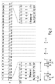
- Fig. 1 shows the signal of the recorded track S1.
- the signal track S1 contains bit information every 40 ms.
- Each frame signal F identifies a self-contained area, the data recorded in the helical tracks.
- the sequence of 25 frame pulses F shown thus comprises the time of 1 second.
- the recorded signal Sy of the first three frame pulses F is a symmetrical rectangular sequence with a pulse-pause ratio of exactly 50%. It is used for synchronization.
- the synchronization bits are followed by 3 control bits C, which represent control information for the overall system.
- the following 19 bits carry information in groups of hours h (4 bits), minutes m (6 bits) and seconds s (6 bits), each counted in binary and protected with one parity bit P (even parity) per group.
- the described sequence of 25 bits is recorded once every second.
- the subsequent data bits of the frame pulses F4 to F25 are characterized by a pulse / pause ratio of 25% in the case of an H bit and 75% in the case of an L bit.
- Track S1 is equal to track S1 recorded in solution 1.
- Track S1 is a low frequency signal
- track S2 is a high frequency signal.
- the low-frequency signal of track S1 which serves as the basic signal, is used in such a way that a symmetrical sequence of three bits is inserted or added symmetrically in front of and behind the edge on each falling edge of track S1.
- the added bits consist of one or two oscillation trains with a pulse-pause ratio of 50%. This ensures that the amplitude reconstruction for positive and negative sequence of a bit is constant in rewinding operation, which facilitates evaluation.
- the bit length for H bits and L bits is the same here, so that the length of the evaluation window is constant for all bits.
- the maximum bit length results from the permissible shift of the low-frequency time code signal. A value of +/- 3 ms will enable clean identification even in rewinding mode.
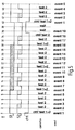
- Fig. 4 shows the basic circuit for recording and regeneration of the signals.
- the left side represents the generation of the signals.
- a microcontroller ⁇ C sets the logical states at out1 and out2 for tracks S1 and S2 together with a time-precise clock OCR.
- Out1 and out2 are synchronized with the clock in a subsequent D flip-flop and are available for recording at Q1 as S1 and at Q2 as S2.
- the reproduction part is shown on the right half of FIG.
- the rectangular signals in1 and in2 are available at the outputs of the amplifiers. This is followed by a multiplexer m, which switches one of these signals at the high-resolution measurement input of a microcontroller ⁇ C in accordance with the predetermined scheme using the signal ctrl.
- This configuration shown is to be used when using a microcontroller ⁇ C, which has a few high-resolution measurement inputs ICR, with which the time between input signal edges can be measured with an accuracy of 250 ns, but which has a large number of normal inputs. If, on the other hand, two of these ICR inputs are available, the lines in1 and in2 must be connected directly to ICR1 and ICR2. The multiplexer m with the control line ctrl can then be omitted. A multiplexing process in the form of a signal Selection in the microcontroller is still possible.
Abstract
Description
Die Erfindung geht aus von einem Verfahren zur Schrägspurmagnetbandaufzeichnung gemäß dem Oberbegriff des Anspruchs 1.The invention is based on a method for recording helical magnetic tape according to the preamble of
Es ist bekannt, bei VHS-Aufzeichngsgeräten für die Synchronisation des Servosystems ein Kontrollsignal in Abständen von 40 ms (in 50 Hz Systemen) in einer Längsspur an der unteren Bandkante aufzuzeichnen. Das Auftreten dieser Signale kann gezählt und als Zeitinformation ausgewertet werden. Nachteilig hierbei ist, daß die Kassette immer bis zum Bandanfang transportiert werden muß, um einen Absolutwert ermitteln zu können.It is known in VHS recording devices for the synchronization of the servo system to record a control signal at intervals of 40 ms (in 50 Hz systems) in a longitudinal track on the lower band edge. The occurrence of these signals can be counted and evaluated as time information. The disadvantage here is that the cassette must always be transported to the beginning of the tape in order to be able to determine an absolute value.
Ferner wurde im Jahr 1986 daß Control Track Longitudinal CTL-System für VHS eingeführt. Durch zeitliche Variation der bislang nicht benutzten Rückflanke des Servosynchronsignales kann alle 40 ms ein Informationsbit übertragen werden. Ein Zeitcoder ist vorgesehen, wobei alle zwei 2 s ein komplettes Datenwort zur Verfügung steht. Nachteilig ist hierbei die Auflösung von 2 s und die relative Codierung der Framepulse.Furthermore, the Control Track Longitudinal CTL system for VHS was introduced in 1986. An information bit can be transmitted every 40 ms by varying the trailing edge of the servo synchronous signal, which was not previously used. A time encoder is provided, with a complete data word being available every two seconds. The disadvantage here is the resolution of 2 s and the relative coding of the frame pulses.
Bei professionellen Geräten hat sich der Zeitcode gemäß IEC 461 bewährt. Mit hoher Auflösung (500 µs/Bit im Longitudinal Time Code LTC) sind sowohl in der Längs- als auch in der Schrägspur Zeitinformationen eingeschachtelt. Nachteilig hierbei ist die hohe Auflösung. Sie verhindert bei hohen Bandtransportgeschwindigkeiten ein Auslesen des Absolutwertes.The time code according to IEC 461 has proven itself for professional devices. With high resolution (500 µs / bit in the longitudinal time code LTC), time information is nested in both the longitudinal and the helical track. The disadvantage here is the high resolution. It prevents the absolute value from being read out at high belt transport speeds.
Der Erfindung liegt die Aufgabe zugrunde, für ein digitales Aufzeichnungsverfahen von Video- und Audiosignalen ein Zeitcodiersystem hoher Auflösung zu erstellen, das bei hohen Bandtransportgeschwindigkeiten (Suchlauf/Vor- bzw. Rücklauf) die Zeitmarken lesen kann. Diese Aufgabe wird durch die im Anspruch 1 angegebene Erfindung gelöst. Vorteilhafte Weiterbildungen der Erfindung sind in den Unteransprüchen angegeben.The object of the invention is to create a high-resolution time coding system for a digital recording method of video and audio signals, which can read the time stamps at high tape transport speeds (search / advance or reverse). This object is achieved by the invention specified in
Bei dem erfindungsgemäßen Aufzeichnungsverfahren wird eine Längsspuraufzeichnung verwendet, wobei die Rückflankenmodulation bei den Phasenreferenzimpulsen auf der Synchronspur wegen deren großen Auflösungsanforderungen und der dadurch bedingten hohen Frequenz nicht möglich ist. Das erfindungsgemäße Aufzeichnungsverfahren soll je nach Ausbaustufe mit einer oder zwei zusätzlichen Längsspuren auskommen. Die aufzuzeichnende Zeitcodeinformation wird in zwei Anteile zerlegt. Ein Anteil enthält die relevanten Werte wie Stunden/Minuten/Sekunden (h/m/s). Dieser Anteil wird in einer ersten Spur mit einem Bitabstand aufgezeichnet, der auch bei hohen Bandgeschwindigkeiten gelesen werden kann. Der zweite Anteil enthält die Framezählinformation und wird entweder in einer separaten Spur aufgezeichnet (Lösung 1) oder aber in das Signal der ersten Spur durch Frequenztrennung eingeschachtelt (Lösung 2).In the recording method according to the invention, a longitudinal track recording is used, the trailing edge modulation of the phase reference pulses on the synchronous track not being possible because of their high resolution requirements and the resulting high frequency. The recording method according to the invention should make do with one or two additional longitudinal tracks, depending on the expansion stage. The time code information to be recorded is broken down into two parts. A portion contains the relevant values such as hours / minutes / seconds (h / m / s). This portion is recorded in a first track with a bit spacing that can be read even at high tape speeds. The second part contains the frame count information and is either recorded in a separate track (solution 1) or nested in the signal of the first track by frequency separation (solution 2).
Das Signal der Spur 1 (weiterhin S1 benannt) enthält alle 40 ms eine Bitinformation. Jedes Framesignal kennzeichnet einen in sich geschlossenen Bereich, der in den Schrägspuren aufgezeichneten Daten. Es wird dem Servosystem von der Videosignalverarbeitung zugeführt, hat eine Zeitdauer von 40 ms und dient zur Synchronisation. Ein Abschnitt von 25 Frameimpulsen umfaßt somit nur die Zeit von einer Sekunde. Das aufgezeichnete Signal der ersten drei Frameimpulse ist eine symmetrische Rechteckfolge mit einem Puls-Pausenverhältnis von exakt 50 %. Sie dient zur Synchronisation. Die nachfolgenden Datenbits sind durch ein Puls/Pausenverhältnis von 25 % im Falle eines H-Bits und 75 % im Falle eines L-Bits gekennzeichnet. Die Auswertung umfaßt Zählstufen, die während des H-Zustandes des Eingangssignales inkrementieren und während des L-Zustandes dekrementieren. Bei jeder positiven Flanke wird der Zählerstand abgespeichert, der Zähler danach wieder gelöscht. Der Zählerwert wird auf 0, positiv oder negativ getestet. Die jeweilige Entscheidung liefert ein Synchronbit, H-Bit, L-Bit.The signal of track 1 (also named S1) contains bit information every 40 ms. Each frame signal identifies a self-contained area, the data recorded in the helical tracks. It is fed to the servo system by video signal processing, has a duration of 40 ms and is used for synchronization. A section of 25 frame pulses thus only covers the time of one second. The recorded signal of the first three frame pulses is a symmetrical rectangular sequence with a pulse-pause ratio of exactly 50%. It is used for synchronization. The subsequent data bits are characterized by a pulse / pause ratio of 25% in the case of an H bit and 75% in the case of an L bit. The evaluation includes counter stages that increment during the H state of the input signal and decrement during the L state. With every positive edge, the counter status is saved and the counter is then deleted again. The counter value is tested for 0, positive or negative. The respective decision provides a synchronous bit, H bit, L bit.
Den Synchronisationsbits folgen 3 Kontrollbits, die für das Ge samtsystem Steuerinformationen darstellen. Beispielsweise: Anzahl der Spuren/frame (abhängig von Netzfrequenz 50/60 Hz), das Bildseitenverhältnis (16:9 oder 4:3) und ob HD-( High Definition) oder SD-(Standard Definition) Signale bei der Aufzeichnung verwendet wurden.The synchronization bits are followed by 3 control bits, which are necessary for the Ge entire system display tax information. For example: number of tracks / frame (depending on
Alternative Verwendung dieser Bits ist auch in Kombinatorik mit 2³=8 darstellbaren Zuständen möglich. Eine Zuordnung der Kontrollbits könnte wie folgt aussehen 011 ≡ Longplay, HD, 16:9, 50Hz
Die folgenden 19 Bits tragen gruppenweise die Information über Stunden (4 Bit), Minuten (6 Bit) und Sekunden (6 Bit), jeweils binär gezählt und mit je mit einem Paritätsbit (gerade Parität) pro Gruppe geschützt. Die beschriebene Sequenz aus 25 Bits wird jede Sekunde einmalig aufgezeichnet.Alternative use of these bits is also possible in combinatorics with 2³ = 8 representable states. The control bits could be assigned as follows 011 ≡ Longplay, HD, 16: 9, 50Hz
The following 19 bits carry information in groups about hours (4 bits), minutes (6 bits) and seconds (6 bits), each counted in binary and protected with one parity bit (even parity) per group. The described sequence of 25 bits is recorded once every second.
Das Signal der Spur 2 (weiterhin S2 genannt) beinhaltet für jeden Frameimpuls ein Pattern. Für jeden der 25 abgebildeten Frameimpulse existiert ein Pattern aus 6 Bit, das synchron mit jeder Frameinformation aus S1 startet, jedoch vor Ablauf der Frameintervalle endet. Dieses Pattern beinhaltet auf 5 Bit die Zählinformation für die Framenummer, das sechste Bit dient zur Paritätsprüfung. Die logischen Zustände sind durch die Puls-Pausenverhältnisse der einzelnen Bits gekennzeichnet. Es beträgt 33 % im Falle eines H-Bits und 66 % in Falle eines L-Bits. Die Werte 25 %, 50 %, 75 % für S1 Signale und 33 %, 66 % für S2 Signale sind gewählt worden, um alle Signale mit einem einzelnen Takt erzeugen zu können.The signal of track 2 (also called S2) contains a pattern for each frame pulse. There is a 6-bit pattern for each of the 25 frame pulses shown, which starts synchronously with every frame information from S1, but ends before the frame intervals expire. This pattern contains 5 bits of count information for the frame number, the sixth bit is used for parity checking. The logical states are characterized by the pulse-pause ratios of the individual bits. It is 33% in the case of an H bit and 66% in the case of an L bit. The
Die Information aus Spur 1 dient zur Synchronisation (Zählerstandzuordnung) beider Spuren und trägt den Zeitzählwert geringer Auflösung (h/m/s). Sie ist damit immer erforderlich. Spur 2 trägt eine abhängige, hochaufgelöste Zeitinformation, deren zeitliche Ereignisse synchron mit Änderung in der Spur 1 erfolgen.The information from
Alle Informationen werden in einer Spur aufgezeichnet. Signale verschiedener Wichtung werden als unterschiedliche Frequenzen aufgezeichnet. Im schnellen Vorlauf es ist nicht sinnvoll, Framenummern zu ermitteln, die in der Anzeige nicht mehr darstellbar sind.All information is recorded on one track. Signals of different weights are recorded as different frequencies. In a fast forward it makes no sense to determine frame numbers that can no longer be displayed.
Vorzugsweise wird ein hochfrequentes Signal für die Feinauflösung (Framenummern) und ein niederfrequentes für die Normalauflösung (h/m/s) in einer Spur aufeinanderfolgend aufgezeichnet. Als Basissignal (niederfrequent) wird das vorher beschriebene S1 Signal verwendet, wobei die fallende Flanke jedes in S1 aufgezeichneten Pulses mit einer Folge von 6 Bit zeitlich verschoben wird. Dabei wird symmetrisch vor und hinter der Flanke eine symmetrische Folge von jeweils 3 Bit ein bzw. hinzugefügt. Es besteht dabei jedes dieser Bits aus einem oder zwei Schwingungszügen, mit einem Puls-Pausenverhältnis von 50 %. Hierdurch ist gewährleistet, daß im Umspulbetrieb die Amplitudenreduktion für positive und negative Impulse eines Bits konstant ist, was eine Auswertung erleichtert. Die Bitlänge für H-Bits und L-Bits ist gleich. Dies gewährleistet, daß die Länge des Auswertefensters für alle Bits konstant ist. Die maximale Bitlänge ergibt sich durch die zulässige Verschiebung des niederfrequenten Zeitcodesignales. Ein Wert von +/- 3 ms wird auch im Umspulbetrieb eine saubere Indentifikation ermöglichen. Besondere Aufmerksamkeit liegt dabei auf den drei Synchronisierbits in den Frameintervallen 1 - 3. Dabei unterbleibt die Einschachtelung des hochfrequenten Zeitcodes während dieser Phase, um ein Erkennen des Datensequenzbeginns auf jeden Fall sicherzustellen. Der Framezähler zählt normal weiter, die Rückflanken der Preamblepulse werden jedoch nicht zeitlich moduliert. Mit dem ersten Kontrollbit wird die Einschachtelung der hochausgelösten Zeitcodeinformation dann fortgesetzt.A high-frequency signal for fine resolution (frame numbers) and a low-frequency signal for normal resolution (h / m / s) are preferably recorded in succession in one track. The previously described S1 signal is used as the base signal (low frequency), the falling edge of each pulse recorded in S1 being shifted in time with a sequence of 6 bits. A symmetrical sequence of 3 bits is added or added symmetrically in front of and behind the edge. Each of these bits consists of one or two oscillation trains with a pulse-pause ratio of 50%. This ensures that the amplitude reduction for positive and negative pulses of a bit is constant in rewinding operation, which facilitates evaluation. The bit length for H bits and L bits is the same. This ensures that the length of the evaluation window is constant for all bits. The maximum bit length results from the permissible shift of the low-frequency time code signal. A value of +/- 3 ms will also enable clean identification in rewinding mode. Particular attention is paid to the three synchronization bits in frame intervals 1 - 3. The high-frequency time code is not interleaved during this phase to ensure that the start of the data sequence is guaranteed in any case. The frame counter continues to count normally, but the trailing edges of the preamble pulses are not modulated in time. The nesting of the highly triggered time code information is then continued with the first control bit.
Die Vorteile der Erfindung liegen im folgenden darin: Die Erfindung stellt eine kostenoptimale Lösung der Zeitcodeproblematik dar. Bei der Wahl der Lösung 1 kann nach Einlegen der Kassette sofort im Suchlaufbetrieb erkannt werden, in welche Richtung das Band bewegt werden muß, um so schnell wie möglich die gesamte Zeitinformation lesen und anzeigen zu können. Das System kehrt danach an den Framebeginn zurück, der beim Einlegen der Kassette zuerst erkannt wurde.The advantages of the invention are as follows: The invention represents a cost-optimal solution to the time code problem. When selecting
Bei Verwendung der Lösung 2 ist dieses im Suchlaufbetrieb nur eingeschränkt möglich. Bei den Preambleimpulsen fehlen Daten, und die notwendige Erkennungssicherheit ist nur bis zur 3-fachen Suchlaufgeschwindigkeit gegeben. Daneben zeichnet sich die Lösung 2 durch hohe Kosteneffizienz aus, da nur jeweils die Aufnahme-Wiedergabeelektronik für einen Kanal zur Verfügung stehen muß und nur ein Kopf benötigt wird. Durch die zur Verfügung stehende größere Spurbreite (VHS Einzelaudiospur 1 mm, Stereospur jeweils 0,35 mm) ist das System sehr robust.When using
Bei Umspulbetrieb wird in Lösung 1 ganz auf die Feinauflösung verzichtet, und die Daten aus S1 werden ausgewertet. Die Lösung 2 beinhaltet die Abschaltung automatisch, da bei größerer Bandvorschubgeschwindigkeit die eingeschachtelten höherfrequenten Anteile vom gesamten Wiedergabesystem so stark gedämpft werden, daß kein digitales Zeitsignal mehr aus ihnen gewonnen werden kann.In the case of rewinding,
Eine zeitliche Trennung der Gruppen wird durchgeführt, da die Zeitcodeinformationen nacheinander aufgezeichnet werden.The groups are separated in time since the time code information is recorded one after the other.
Die Erfindung wird im folgenden anhand der Zeichnung erläutert. Darin zeigen:
- Fig. 1
- die
aufgezeichnete Spur 51der Lösung 1, - Fig. 2
- die aufgezeichnete Spur 52
der Lösung 1, - Fig. 3
- die aufgezeichneten Spuren S1 und S2 der
Lösung 2, - Fig. 4
- die prinzipielle Schaltung zur Aufzeichnung und Regenerierung der Signale und
- Fig. 5
- die Zuordnung der Signale S1, S2.
- Fig. 1
- the recorded
track 51 ofsolution 1, - Fig. 2
- the recorded track 52 of
solution 1, - Fig. 3
- the recorded tracks S1 and S2 of
solution 2, - Fig. 4
- the basic circuit for recording and regenerating the signals and
- Fig. 5
- the assignment of the signals S1, S2.
Fig. 1 zeigt das Signal der aufgezeichneten Spur S1. Das Signal der Spur S1 enthält alle 40 ms eine Bitinformation. Jedes Framesignal F kennzeichnet einen in sich geschlossenen Bereich, der in den Schrägspuren aufgezeichneten Daten. Die dargestellte Sequenz von 25 Frameimpulsen F umfaßt somit die Zeit von 1 Sekunde. Das aufgezeichnete Signal Sy der ersten drei Frameimpulse F ist eine symmetrische Rechteckfolge mit einem Puls-Pausenverhältnis von exakt 50 %. Sie dient zur Synchronisation.Fig. 1 shows the signal of the recorded track S1. The signal track S1 contains bit information every 40 ms. Each frame signal F identifies a self-contained area, the data recorded in the helical tracks. The sequence of 25 frame pulses F shown thus comprises the time of 1 second. The recorded signal Sy of the first three frame pulses F is a symmetrical rectangular sequence with a pulse-pause ratio of exactly 50%. It is used for synchronization.
Den Synchronisationsbits folgen 3 Kontrollbits C, die für das Gesamtsystem Steuerinformationen darstellen. c0 Netzfrequenz 50/60 Hz, c1 das Bildseitenverhältnis 16:9 oder 4:3 und c2 ob HD- oder SD-Signale bei der Aufzeichnung verwendet wurden.The synchronization bits are followed by 3 control bits C, which represent control information for the overall system.
Die folgenden 19 Bits tragen gruppenweise die Information über Stunden h (4 Bit), Minuten m(6 Bit) und Sekunden s (6 Bit), jeweils binär gezählt und mit je mit einem Paritätsbit P(gerade Parität) pro Gruppe geschützt. Die beschriebene Sequenz aus 25 Bits wird jede Sekunde einmalig aufgezeichnet.The following 19 bits carry information in groups of hours h (4 bits), minutes m (6 bits) and seconds s (6 bits), each counted in binary and protected with one parity bit P (even parity) per group. The described sequence of 25 bits is recorded once every second.
Die nachfolgenden Datenbits der Frameimpulse F4 bis F25 sind durch ein Puls/Pausenverhältnis von 25 % in Falle eines H-Bits und 75 % im Falle eines L-Bits gekennzeichnet.The subsequent data bits of the frame pulses F4 to F25 are characterized by a pulse / pause ratio of 25% in the case of an H bit and 75% in the case of an L bit.
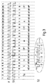
Fig. 2 zeigt die aufgezeichnete Spur S2 der Lösung 1. Für jeden der 25 abgebildeten Frameimpulse existiert ein Pattern aus 6 Bit, das synchron mit jeder Frameinformation aus S1 startet, je-, doch vor Ablauf der Frameintervalle endet. Dieses Pattern hat in den ersten 5 Bit die Zählinformation f4 bis f0 für die Framenummer F1, das sechte Bit dient zur Paritätsprüfung. Ein Pattern hat eine Länge b und ein Bit die Länge a. Ein Längenverhälnis von b zu a gleich 6 wird bemessen. Die Länge des anzeigenden Impulses ob high H oder low L ist mit c festgelegt und das Längenverhältnis von a zu c gleich 3 wird bemessen.2 shows the recorded track S2 of
Fig. 3 zeigt die Aufzeichnung der Spur S1 und S2 der Lösung 2. Die Spur S1 ist gleich der in der Lösung 1 aufgezeichnet Spur S1. Die Spur S1 ist ein niederfrequentes Signal, und die Spur S2 ist ein hochfrequentes Signal. Das als Basissignal dienende niederfrequente Signal der Spur S1 wird dermaßen ausgenutzt, daß bei jeder fallenden Flanke der Spur S1 symmetrisch vor und hinter der Flanke eine symmetrische Folge von jeweils drei Bits ein- bzw. hinzugefügt wird. Die hinzugefügten Bits bestehen dabei aus einem oder zwei Schwingungszügen mit einem Puls-Pausenverhältnis von 50 %. Hierdurch ist gewährleistet, daß im Umspulbetrieb die Amplitudenrekonstruktion für positive und negative Folge eines Bits konstant ist, was eine Auswertung erleichtert. Die Bitlänge für H-Bits und L-Bits ist hierbei gleich, so daß die Länge des Auswertefensters für alle Bits konstant ist. Die maximale Bitlänge ergibt sich durch die zulässige Verschiebung des niederfrequenten Zeitcodesignales. Ein Wert von +/- 3 ms wird auch im Umspulbetrieb eine saubere Identifikation ermöglichen.3 shows the recording of tracks S1 and S2 of
Fig. 4 zeigt die prinzipielle Schaltung zur Aufzeichnung und Regenerierung der Signale. Die linke Seite stellt die Generierung der Signale dar. Ein Microcontroller µC stellt für die Spuren S1 und S2 die logischen Zustände an out1 bzw. out2 zusammen mit einem zeitgenauen Takt OCR. Out1 und out2 werden in einem nachfolgenden D-Flip Flop mit dem Takt synchronisiert und stehen an Q1 als S1 bzw. an Q2 als S2 zur Aufzeichnung zur Verfügung. Auf der rechten Hälfte von Fig. 4 ist der Wiedergabeteil dargestellt. An den Ausgängen der Verstärker stehen die rechteckigen Signale in1 sowie in2 zur Verfügung. Es folgt ein Multiplexer m, der eines dieser Signale an dem hochauflösenden Meßeinganges eines Microcontrollers µC nach vorgegebenen Schema mit Hilfe des Signales ctrl schaltet. Diese dargestellte Konfiguration ist bei Verwendung eines Microkontrollers µC zu verwenden, der wenige hochauflösende Meßeingänge ICR aufweist, mit denen sich die Zeit zwischen Eingangssignalflanken mit einer Genauigkeit von 250 ns messen läßt, welche aber über eine Vielzahl von Normalein-Ausgängen verfügt. Stehen dagegen zwei dieser ICR-Eingänge zur Verfügung, so sind die Leitungen in1 und in2 direkt mit ICR1 bzw. ICR2 zu verbinden. Der Multiplexer m mit der Steuerleitung ctrl kann dann entfallen. Ein Multiplexvorgang in Form einer Signal selektion im Microcontroller ist trotzdem möglich.Fig. 4 shows the basic circuit for recording and regeneration of the signals. The left side represents the generation of the signals. A microcontroller µC sets the logical states at out1 and out2 for tracks S1 and S2 together with a time-precise clock OCR. Out1 and out2 are synchronized with the clock in a subsequent D flip-flop and are available for recording at Q1 as S1 and at Q2 as S2. The reproduction part is shown on the right half of FIG. The rectangular signals in1 and in2 are available at the outputs of the amplifiers. This is followed by a multiplexer m, which switches one of these signals at the high-resolution measurement input of a microcontroller μC in accordance with the predetermined scheme using the signal ctrl. This configuration shown is to be used when using a microcontroller µC, which has a few high-resolution measurement inputs ICR, with which the time between input signal edges can be measured with an accuracy of 250 ns, but which has a large number of normal inputs. If, on the other hand, two of these ICR inputs are available, the lines in1 and in2 must be connected directly to ICR1 and ICR2. The multiplexer m with the control line ctrl can then be omitted. A multiplexing process in the form of a signal Selection in the microcontroller is still possible.
In Fig. 5 ist die Zuordnung der Signale S1, S2 und ctrl über einen Zeitraum von 48 ms dargestellt. Die schraffierten Bereiche stellen mit ihrer rechten und linken Begrenzung die Umschaltungspunkte für H-Bits bzw. L-Bits dar. Beide Signale sind miteinander verkoppelt. Im Zeitraum T0 wartet das Auswertesystem auf eine positive Flanke aus S1 (ctrl=H). Ist dieses Ereignis aufgetreten, so wird auf den zweiten Kanal umgeschaltet (ctrl=L) und der Zustand von S1 abgefragt. Die nächste Signaländerung, in der Fig.5 mit event2 bzw.event3 bezeichnet, wird vom Microcontroller registriert und wie im Diagrammfeld beschrieben umgesetzt. Die Einträge (event2, 3 sowie event4, 5 und folgend) stellen mögliche Signaländerungspunkte dar, es wird jedoch abhängig von logischen Zustand, nur entweder event 2 oder event 3 geben.5 shows the assignment of the signals S1, S2 and ctrl over a period of 48 ms. With their right and left boundaries, the hatched areas represent the switching points for H bits and L bits. Both signals are coupled to one another. In the period T0, the evaluation system waits for a positive edge from S1 (ctrl = H). If this event has occurred, the system switches to the second channel (ctrl = L) and queries the status of S1. The next signal change, designated event2 or event3 in FIG. 5, is registered by the microcontroller and implemented as described in the diagram field. The entries (event2, 3 and event4, 5 and following) represent possible signal change points, but depending on the logical state, there will only be either
Claims (10)
Applications Claiming Priority (2)
| Application Number | Priority Date | Filing Date | Title |
|---|---|---|---|
| DE4241986A DE4241986A1 (en) | 1992-12-12 | 1992-12-12 | Procedure for inclined track magnetic tape recording |
| DE4241986 | 1992-12-12 |
Publications (3)
| Publication Number | Publication Date |
|---|---|
| EP0602469A2 true EP0602469A2 (en) | 1994-06-22 |
| EP0602469A3 EP0602469A3 (en) | 1995-11-29 |
| EP0602469B1 EP0602469B1 (en) | 2000-04-12 |
Family
ID=6475115
Family Applications (1)
| Application Number | Title | Priority Date | Filing Date |
|---|---|---|---|
| EP93119477A Expired - Lifetime EP0602469B1 (en) | 1992-12-12 | 1993-12-03 | Method and apparatus for recording on a magnetic tape with slant tracks |
Country Status (7)
| Country | Link |
|---|---|
| US (1) | US5644675A (en) |
| EP (1) | EP0602469B1 (en) |
| JP (1) | JP3490484B2 (en) |
| KR (1) | KR100280574B1 (en) |
| CN (1) | CN1039948C (en) |
| DE (2) | DE4241986A1 (en) |
| ES (1) | ES2145759T3 (en) |
Cited By (1)
| Publication number | Priority date | Publication date | Assignee | Title |
|---|---|---|---|---|
| EP0913998A1 (en) * | 1997-04-15 | 1999-05-06 | Matsushita Electric Industrial Co., Ltd. | Recording and reproducing device |
Families Citing this family (3)
| Publication number | Priority date | Publication date | Assignee | Title |
|---|---|---|---|---|
| JPH1066036A (en) * | 1996-08-15 | 1998-03-06 | Oki Electric Ind Co Ltd | Tv system converter |
| CN1161780C (en) * | 1999-01-07 | 2004-08-11 | 日本胜利株式会社 | Method and device for data recording |
| JP2001118366A (en) * | 1999-10-20 | 2001-04-27 | Brother Ind Ltd | Device and method for detecting discontinuous position |
Citations (6)
| Publication number | Priority date | Publication date | Assignee | Title |
|---|---|---|---|---|
| US3681524A (en) * | 1970-06-16 | 1972-08-01 | Columbia Broadcasting Syst Inc | Multiple frequency time code generator and reader |
| WO1984002221A1 (en) * | 1982-11-30 | 1984-06-07 | George Saint | Data storage devices |
| DE3309029A1 (en) * | 1983-03-14 | 1984-09-20 | Winfried Dipl.-Ing.(FH) 8000 München Walter | Method of determining the instantaneous tape length of a video magnetic tape and video magnetic tapes played in accordance with this method |
| EP0211388A2 (en) * | 1985-08-07 | 1987-02-25 | Hitachi, Ltd. | Control signal recording apparatus of magnetic recording/reproducing apparatus |
| US4703311A (en) * | 1986-06-09 | 1987-10-27 | Gse Electronic Systems, Inc. | Method and apparatus for transferring an information code onto the synchronization track of a video tape and a video tape produced according to said method |
| EP0320744A2 (en) * | 1987-12-15 | 1989-06-21 | Nokia (Deutschland) GmbH | Video recorder with a device for recording an additional control track on a video tape |
Family Cites Families (8)
| Publication number | Priority date | Publication date | Assignee | Title |
|---|---|---|---|---|
| GB1577133A (en) * | 1976-03-19 | 1980-10-22 | Rca Corp | Video information record and playback apparatus |
| US4665431A (en) * | 1982-06-24 | 1987-05-12 | Cooper J Carl | Apparatus and method for receiving audio signals transmitted as part of a television video signal |
| US4516164A (en) * | 1982-10-21 | 1985-05-07 | Stypher Corporation | Apparatus for decoding video address code signals |
| US4663678A (en) * | 1984-06-18 | 1987-05-05 | Odetics, Inc. | System for writing and reading digital data interspersed with analog audio frequency data on magnetic recording tape |
| JPH0664777B2 (en) * | 1986-10-03 | 1994-08-22 | シンワ株式会社 | Tape pre-winder tape winding end detection device |
| CN1049978A (en) * | 1989-05-03 | 1991-03-20 | 何吉松 | Outer space chess |
| NL9000635A (en) * | 1990-03-20 | 1991-10-16 | Philips Nv | DIGITAL RECORDING AND DISPLAY SYSTEM. |
| JP2741112B2 (en) * | 1991-03-29 | 1998-04-15 | シャープ株式会社 | Digital modulation method and digital modulation device |
-
1992
- 1992-12-12 DE DE4241986A patent/DE4241986A1/en not_active Withdrawn
-
1993
- 1993-12-03 ES ES93119477T patent/ES2145759T3/en not_active Expired - Lifetime
- 1993-12-03 EP EP93119477A patent/EP0602469B1/en not_active Expired - Lifetime
- 1993-12-03 DE DE59310007T patent/DE59310007D1/en not_active Expired - Fee Related
- 1993-12-09 KR KR1019930026951A patent/KR100280574B1/en not_active IP Right Cessation
- 1993-12-11 CN CN93120820A patent/CN1039948C/en not_active Expired - Fee Related
- 1993-12-13 JP JP31195093A patent/JP3490484B2/en not_active Expired - Fee Related
-
1995
- 1995-03-27 US US08/410,417 patent/US5644675A/en not_active Expired - Fee Related
Patent Citations (6)
| Publication number | Priority date | Publication date | Assignee | Title |
|---|---|---|---|---|
| US3681524A (en) * | 1970-06-16 | 1972-08-01 | Columbia Broadcasting Syst Inc | Multiple frequency time code generator and reader |
| WO1984002221A1 (en) * | 1982-11-30 | 1984-06-07 | George Saint | Data storage devices |
| DE3309029A1 (en) * | 1983-03-14 | 1984-09-20 | Winfried Dipl.-Ing.(FH) 8000 München Walter | Method of determining the instantaneous tape length of a video magnetic tape and video magnetic tapes played in accordance with this method |
| EP0211388A2 (en) * | 1985-08-07 | 1987-02-25 | Hitachi, Ltd. | Control signal recording apparatus of magnetic recording/reproducing apparatus |
| US4703311A (en) * | 1986-06-09 | 1987-10-27 | Gse Electronic Systems, Inc. | Method and apparatus for transferring an information code onto the synchronization track of a video tape and a video tape produced according to said method |
| EP0320744A2 (en) * | 1987-12-15 | 1989-06-21 | Nokia (Deutschland) GmbH | Video recorder with a device for recording an additional control track on a video tape |
Cited By (3)
| Publication number | Priority date | Publication date | Assignee | Title |
|---|---|---|---|---|
| EP0913998A1 (en) * | 1997-04-15 | 1999-05-06 | Matsushita Electric Industrial Co., Ltd. | Recording and reproducing device |
| EP0913998A4 (en) * | 1997-04-15 | 1999-05-12 | ||
| US6546191B1 (en) | 1997-04-15 | 2003-04-08 | Matsushita Electric Industrial Co., Ltd. | Recording-reproducing apparatus for progress TV system |
Also Published As
| Publication number | Publication date |
|---|---|
| EP0602469A3 (en) | 1995-11-29 |
| EP0602469B1 (en) | 2000-04-12 |
| ES2145759T3 (en) | 2000-07-16 |
| JP3490484B2 (en) | 2004-01-26 |
| KR100280574B1 (en) | 2001-03-02 |
| JPH06259944A (en) | 1994-09-16 |
| CN1039948C (en) | 1998-09-23 |
| CN1089050A (en) | 1994-07-06 |
| DE59310007D1 (en) | 2000-05-18 |
| DE4241986A1 (en) | 1994-06-16 |
| US5644675A (en) | 1997-07-01 |
| KR940015974A (en) | 1994-07-22 |
Similar Documents
| Publication | Publication Date | Title |
|---|---|---|
| DE2618031C2 (en) | Evaluation circuit for binary data | |
| DE2530482C2 (en) | Servo system for a video recorder | |
| DE3018602C2 (en) | ||
| DE3809179C2 (en) | Method and device for recording and reproducing a digital signal using a rotary head | |
| DE2427225C3 (en) | Circuit arrangement for demodulating digital information | |
| CH619314A5 (en) | ||
| AT389787B (en) | TIME COUNTING GENERATOR | |
| DE2841728A1 (en) | METHOD AND CIRCUIT FOR THE PLAYBACK OF A VIDEO SIGNAL STORED ON MAGNETIC TAPE WITH VARIABLE SPEED | |
| DE2500696A1 (en) | METHOD OF DIVIDING A CONTINUOUS SIGNAL | |
| DE3004799C2 (en) | ||
| DE2140741A1 (en) | Order to determine the occurrence of an event | |
| DE3236311A1 (en) | DATA SYNCHRONIZER | |
| DE2924695C2 (en) | ||
| DE2711980B2 (en) | Tape position counter in a video recording and playback device for displaying the current position of the magnetic tape with respect to a rotating head assembly | |
| DE2832337A1 (en) | INFORMATION RECORDING AND DISPLAYING DEVICE | |
| EP0602469B1 (en) | Method and apparatus for recording on a magnetic tape with slant tracks | |
| EP0198841B1 (en) | Track post-control system for a magnetic tape unit with transverse track recording | |
| DE2849983A1 (en) | CIRCUIT ARRANGEMENT AND PROCEDURE FOR AUTOMATIC DIFFERENCE BETWEEN SEVERAL STANDARD INFORMATION CONTAINED IN A TIME CODE SIGNAL | |
| DE4444783C2 (en) | Method for recording / reproducing gray-coded data signals and decoding circuit for a hard disk drive | |
| DE2912754C2 (en) | ||
| DE2055538A1 (en) | Arrangement for finding information recorded on magnetic tape | |
| DE2849982A1 (en) | CIRCUIT ARRANGEMENT AND PROCEDURE FOR AUTOMATIC DIFFERENCE BETWEEN SEVERAL STANDARD INFORMATION CONTAINED IN A TIME CODE SIGNAL | |
| DE3229760C2 (en) | Arrangement for setting a playback magnetic head in the center of a data track to be played back on a magnetic recording medium | |
| DE2016447A1 (en) | Circuit for multi-track recording and reproduction of binary information with high bit density | |
| DE3225406C2 (en) |
Legal Events
| Date | Code | Title | Description |
|---|---|---|---|
| PUAI | Public reference made under article 153(3) epc to a published international application that has entered the european phase |
Free format text: ORIGINAL CODE: 0009012 |
|
| AK | Designated contracting states |
Kind code of ref document: A2 Designated state(s): DE ES FR GB IT |
|
| PUAL | Search report despatched |
Free format text: ORIGINAL CODE: 0009013 |
|
| AK | Designated contracting states |
Kind code of ref document: A3 Designated state(s): DE ES FR GB IT |
|
| 17P | Request for examination filed |
Effective date: 19960530 |
|
| 17Q | First examination report despatched |
Effective date: 19961203 |
|
| GRAG | Despatch of communication of intention to grant |
Free format text: ORIGINAL CODE: EPIDOS AGRA |
|
| RTI1 | Title (correction) |
Free format text: METHOD AND APPARATUS FOR RECORDING ON A MAGNETIC TAPE WITH SLANT TRACKS |
|
| GRAG | Despatch of communication of intention to grant |
Free format text: ORIGINAL CODE: EPIDOS AGRA |
|
| GRAG | Despatch of communication of intention to grant |
Free format text: ORIGINAL CODE: EPIDOS AGRA |
|
| GRAH | Despatch of communication of intention to grant a patent |
Free format text: ORIGINAL CODE: EPIDOS IGRA |
|
| GRAH | Despatch of communication of intention to grant a patent |
Free format text: ORIGINAL CODE: EPIDOS IGRA |
|
| GRAA | (expected) grant |
Free format text: ORIGINAL CODE: 0009210 |
|
| ITF | It: translation for a ep patent filed |
Owner name: JACOBACCI & PERANI S.P.A. |
|
| AK | Designated contracting states |
Kind code of ref document: B1 Designated state(s): DE ES FR GB IT |
|
| GBT | Gb: translation of ep patent filed (gb section 77(6)(a)/1977) |
Effective date: 20000413 |
|
| REF | Corresponds to: |
Ref document number: 59310007 Country of ref document: DE Date of ref document: 20000518 |
|
| ET | Fr: translation filed | ||
| REG | Reference to a national code |
Ref country code: ES Ref legal event code: FG2A Ref document number: 2145759 Country of ref document: ES Kind code of ref document: T3 |
|
| PLBE | No opposition filed within time limit |
Free format text: ORIGINAL CODE: 0009261 |
|
| STAA | Information on the status of an ep patent application or granted ep patent |
Free format text: STATUS: NO OPPOSITION FILED WITHIN TIME LIMIT |
|
| 26N | No opposition filed | ||
| REG | Reference to a national code |
Ref country code: GB Ref legal event code: IF02 |
|
| PGFP | Annual fee paid to national office [announced via postgrant information from national office to epo] |
Ref country code: GB Payment date: 20051110 Year of fee payment: 13 |
|
| PGFP | Annual fee paid to national office [announced via postgrant information from national office to epo] |
Ref country code: DE Payment date: 20051216 Year of fee payment: 13 |
|
| PGFP | Annual fee paid to national office [announced via postgrant information from national office to epo] |
Ref country code: FR Payment date: 20051222 Year of fee payment: 13 |
|
| PGFP | Annual fee paid to national office [announced via postgrant information from national office to epo] |
Ref country code: ES Payment date: 20051227 Year of fee payment: 13 |
|
| PGFP | Annual fee paid to national office [announced via postgrant information from national office to epo] |
Ref country code: IT Payment date: 20061231 Year of fee payment: 14 |
|
| PG25 | Lapsed in a contracting state [announced via postgrant information from national office to epo] |
Ref country code: DE Free format text: LAPSE BECAUSE OF NON-PAYMENT OF DUE FEES Effective date: 20070703 |
|
| GBPC | Gb: european patent ceased through non-payment of renewal fee |
Effective date: 20061203 |
|
| REG | Reference to a national code |
Ref country code: FR Ref legal event code: ST Effective date: 20070831 |
|
| PG25 | Lapsed in a contracting state [announced via postgrant information from national office to epo] |
Ref country code: GB Free format text: LAPSE BECAUSE OF NON-PAYMENT OF DUE FEES Effective date: 20061203 |
|
| REG | Reference to a national code |
Ref country code: ES Ref legal event code: FD2A Effective date: 20061204 |
|
| PG25 | Lapsed in a contracting state [announced via postgrant information from national office to epo] |
Ref country code: FR Free format text: LAPSE BECAUSE OF NON-PAYMENT OF DUE FEES Effective date: 20070102 Ref country code: ES Free format text: LAPSE BECAUSE OF NON-PAYMENT OF DUE FEES Effective date: 20061204 |
|
| PG25 | Lapsed in a contracting state [announced via postgrant information from national office to epo] |
Ref country code: IT Free format text: LAPSE BECAUSE OF NON-PAYMENT OF DUE FEES Effective date: 20071203 |