EP0602021A2 - Ink jet head and manufacturing method thereof, discharge opening plate for head and manufacturing method thereof, and ink jet apparatus with ink jet head - Google Patents
Ink jet head and manufacturing method thereof, discharge opening plate for head and manufacturing method thereof, and ink jet apparatus with ink jet head Download PDFInfo
- Publication number
- EP0602021A2 EP0602021A2 EP94200483A EP94200483A EP0602021A2 EP 0602021 A2 EP0602021 A2 EP 0602021A2 EP 94200483 A EP94200483 A EP 94200483A EP 94200483 A EP94200483 A EP 94200483A EP 0602021 A2 EP0602021 A2 EP 0602021A2
- Authority
- EP
- European Patent Office
- Prior art keywords
- ink
- discharge opening
- plate
- recording head
- ink jet
- Prior art date
- Legal status (The legal status is an assumption and is not a legal conclusion. Google has not performed a legal analysis and makes no representation as to the accuracy of the status listed.)
- Withdrawn
Links
- 238000004519 manufacturing process Methods 0.000 title claims description 65
- 239000010410 layer Substances 0.000 claims abstract description 92
- XLYOFNOQVPJJNP-UHFFFAOYSA-N water Substances O XLYOFNOQVPJJNP-UHFFFAOYSA-N 0.000 claims abstract description 54
- 239000012790 adhesive layer Substances 0.000 claims abstract description 41
- 238000007599 discharging Methods 0.000 claims description 216
- 239000007788 liquid Substances 0.000 claims description 121
- 238000000034 method Methods 0.000 claims description 117
- 239000000463 material Substances 0.000 claims description 78
- 239000000853 adhesive Substances 0.000 claims description 74
- 229920005989 resin Polymers 0.000 claims description 59
- 239000011347 resin Substances 0.000 claims description 59
- 229910052751 metal Inorganic materials 0.000 claims description 31
- 239000002184 metal Substances 0.000 claims description 31
- 230000001678 irradiating effect Effects 0.000 claims description 11
- 238000000465 moulding Methods 0.000 claims description 11
- 238000005553 drilling Methods 0.000 claims description 7
- 238000005323 electroforming Methods 0.000 claims description 4
- 230000006870 function Effects 0.000 claims description 3
- 239000010408 film Substances 0.000 description 103
- 239000005871 repellent Substances 0.000 description 74
- 230000002940 repellent Effects 0.000 description 73
- 230000001070 adhesive effect Effects 0.000 description 56
- 239000000758 substrate Substances 0.000 description 52
- 230000015572 biosynthetic process Effects 0.000 description 27
- 239000003795 chemical substances by application Substances 0.000 description 22
- 230000000694 effects Effects 0.000 description 22
- 239000011295 pitch Substances 0.000 description 20
- 238000000576 coating method Methods 0.000 description 19
- PXHVJJICTQNCMI-UHFFFAOYSA-N nickel Substances [Ni] PXHVJJICTQNCMI-UHFFFAOYSA-N 0.000 description 19
- CURLTUGMZLYLDI-UHFFFAOYSA-N Carbon dioxide Chemical compound O=C=O CURLTUGMZLYLDI-UHFFFAOYSA-N 0.000 description 16
- 239000011248 coating agent Substances 0.000 description 16
- 230000008569 process Effects 0.000 description 16
- 238000010438 heat treatment Methods 0.000 description 15
- 229920001721 polyimide Polymers 0.000 description 15
- 238000002360 preparation method Methods 0.000 description 15
- 229920002799 BoPET Polymers 0.000 description 13
- 239000005041 Mylar™ Substances 0.000 description 13
- 239000004696 Poly ether ether ketone Substances 0.000 description 13
- 229920002530 polyetherether ketone Polymers 0.000 description 13
- 239000004642 Polyimide Substances 0.000 description 12
- 239000011247 coating layer Substances 0.000 description 12
- 239000011521 glass Substances 0.000 description 12
- 230000001965 increasing effect Effects 0.000 description 11
- 238000003825 pressing Methods 0.000 description 11
- 238000010276 construction Methods 0.000 description 10
- 229910052759 nickel Inorganic materials 0.000 description 10
- 229910052782 aluminium Inorganic materials 0.000 description 8
- 229910002092 carbon dioxide Inorganic materials 0.000 description 8
- 238000005530 etching Methods 0.000 description 8
- 230000006872 improvement Effects 0.000 description 8
- 238000007639 printing Methods 0.000 description 8
- 239000004695 Polyether sulfone Substances 0.000 description 7
- XAGFODPZIPBFFR-UHFFFAOYSA-N aluminium Chemical compound [Al] XAGFODPZIPBFFR-UHFFFAOYSA-N 0.000 description 7
- 229920006393 polyether sulfone Polymers 0.000 description 7
- 230000001681 protective effect Effects 0.000 description 7
- 229920002379 silicone rubber Polymers 0.000 description 7
- ZWEHNKRNPOVVGH-UHFFFAOYSA-N 2-Butanone Chemical compound CCC(C)=O ZWEHNKRNPOVVGH-UHFFFAOYSA-N 0.000 description 6
- 239000001569 carbon dioxide Substances 0.000 description 6
- 230000000052 comparative effect Effects 0.000 description 6
- 238000001723 curing Methods 0.000 description 6
- 229910052731 fluorine Inorganic materials 0.000 description 6
- 238000012986 modification Methods 0.000 description 6
- 230000004048 modification Effects 0.000 description 6
- 239000000047 product Substances 0.000 description 6
- 238000004528 spin coating Methods 0.000 description 6
- 238000012546 transfer Methods 0.000 description 6
- YCKRFDGAMUMZLT-UHFFFAOYSA-N Fluorine atom Chemical compound [F] YCKRFDGAMUMZLT-UHFFFAOYSA-N 0.000 description 5
- 239000004721 Polyphenylene oxide Substances 0.000 description 5
- -1 SUS Chemical class 0.000 description 5
- 238000005520 cutting process Methods 0.000 description 5
- 239000011737 fluorine Substances 0.000 description 5
- 230000002093 peripheral effect Effects 0.000 description 5
- 229920002492 poly(sulfone) Polymers 0.000 description 5
- 239000004945 silicone rubber Substances 0.000 description 5
- 239000000243 solution Substances 0.000 description 5
- 229910001220 stainless steel Inorganic materials 0.000 description 5
- 239000010935 stainless steel Substances 0.000 description 5
- 239000006087 Silane Coupling Agent Substances 0.000 description 4
- RTAQQCXQSZGOHL-UHFFFAOYSA-N Titanium Chemical compound [Ti] RTAQQCXQSZGOHL-UHFFFAOYSA-N 0.000 description 4
- 230000007423 decrease Effects 0.000 description 4
- 238000001035 drying Methods 0.000 description 4
- 239000000203 mixture Substances 0.000 description 4
- 230000036961 partial effect Effects 0.000 description 4
- 229920000728 polyester Polymers 0.000 description 4
- 239000010453 quartz Substances 0.000 description 4
- VYPSYNLAJGMNEJ-UHFFFAOYSA-N silicon dioxide Inorganic materials O=[Si]=O VYPSYNLAJGMNEJ-UHFFFAOYSA-N 0.000 description 4
- 238000012360 testing method Methods 0.000 description 4
- 229910052719 titanium Inorganic materials 0.000 description 4
- 239000010936 titanium Substances 0.000 description 4
- 239000004593 Epoxy Substances 0.000 description 3
- ZMXDDKWLCZADIW-UHFFFAOYSA-N N,N-Dimethylformamide Chemical compound CN(C)C=O ZMXDDKWLCZADIW-UHFFFAOYSA-N 0.000 description 3
- 229920012266 Poly(ether sulfone) PES Polymers 0.000 description 3
- HEMHJVSKTPXQMS-UHFFFAOYSA-M Sodium hydroxide Chemical compound [OH-].[Na+] HEMHJVSKTPXQMS-UHFFFAOYSA-M 0.000 description 3
- 239000006096 absorbing agent Substances 0.000 description 3
- 239000003086 colorant Substances 0.000 description 3
- 239000002131 composite material Substances 0.000 description 3
- 230000002950 deficient Effects 0.000 description 3
- 229920001971 elastomer Polymers 0.000 description 3
- 230000002708 enhancing effect Effects 0.000 description 3
- 238000001746 injection moulding Methods 0.000 description 3
- 230000003287 optical effect Effects 0.000 description 3
- 238000000206 photolithography Methods 0.000 description 3
- 239000004033 plastic Substances 0.000 description 3
- 229920003023 plastic Polymers 0.000 description 3
- 238000007747 plating Methods 0.000 description 3
- 229920000570 polyether Polymers 0.000 description 3
- 229920002620 polyvinyl fluoride Polymers 0.000 description 3
- 230000009467 reduction Effects 0.000 description 3
- 239000005060 rubber Substances 0.000 description 3
- 238000007789 sealing Methods 0.000 description 3
- 229910052710 silicon Inorganic materials 0.000 description 3
- 239000004447 silicone coating Substances 0.000 description 3
- 239000000126 substance Substances 0.000 description 3
- 229910052715 tantalum Inorganic materials 0.000 description 3
- GUVRBAGPIYLISA-UHFFFAOYSA-N tantalum atom Chemical compound [Ta] GUVRBAGPIYLISA-UHFFFAOYSA-N 0.000 description 3
- 238000005406 washing Methods 0.000 description 3
- CBENFWSGALASAD-UHFFFAOYSA-N Ozone Chemical compound [O-][O+]=O CBENFWSGALASAD-UHFFFAOYSA-N 0.000 description 2
- 239000004743 Polypropylene Substances 0.000 description 2
- XUIMIQQOPSSXEZ-UHFFFAOYSA-N Silicon Chemical compound [Si] XUIMIQQOPSSXEZ-UHFFFAOYSA-N 0.000 description 2
- 238000009835 boiling Methods 0.000 description 2
- 239000000919 ceramic Substances 0.000 description 2
- 238000004891 communication Methods 0.000 description 2
- 239000000470 constituent Substances 0.000 description 2
- 230000001276 controlling effect Effects 0.000 description 2
- 230000003247 decreasing effect Effects 0.000 description 2
- 238000013461 design Methods 0.000 description 2
- 230000005611 electricity Effects 0.000 description 2
- 238000010894 electron beam technology Methods 0.000 description 2
- 239000003822 epoxy resin Substances 0.000 description 2
- ZHPNWZCWUUJAJC-UHFFFAOYSA-N fluorosilicon Chemical compound [Si]F ZHPNWZCWUUJAJC-UHFFFAOYSA-N 0.000 description 2
- 230000010354 integration Effects 0.000 description 2
- 238000011835 investigation Methods 0.000 description 2
- 239000007769 metal material Substances 0.000 description 2
- 238000002156 mixing Methods 0.000 description 2
- 238000012856 packing Methods 0.000 description 2
- 238000000059 patterning Methods 0.000 description 2
- BASFCYQUMIYNBI-UHFFFAOYSA-N platinum Chemical compound [Pt] BASFCYQUMIYNBI-UHFFFAOYSA-N 0.000 description 2
- 229920000647 polyepoxide Polymers 0.000 description 2
- 229920000139 polyethylene terephthalate Polymers 0.000 description 2
- 239000005020 polyethylene terephthalate Substances 0.000 description 2
- 239000002952 polymeric resin Substances 0.000 description 2
- 229920006380 polyphenylene oxide Polymers 0.000 description 2
- 229920001155 polypropylene Polymers 0.000 description 2
- 238000011176 pooling Methods 0.000 description 2
- 230000002035 prolonged effect Effects 0.000 description 2
- 238000004080 punching Methods 0.000 description 2
- 238000001454 recorded image Methods 0.000 description 2
- 230000004044 response Effects 0.000 description 2
- 230000002441 reversible effect Effects 0.000 description 2
- 239000004065 semiconductor Substances 0.000 description 2
- 238000000926 separation method Methods 0.000 description 2
- 238000004904 shortening Methods 0.000 description 2
- 239000010703 silicon Substances 0.000 description 2
- 238000004544 sputter deposition Methods 0.000 description 2
- 229920003002 synthetic resin Polymers 0.000 description 2
- 230000004304 visual acuity Effects 0.000 description 2
- KUBDPQJOLOUJRM-UHFFFAOYSA-N 2-(chloromethyl)oxirane;4-[2-(4-hydroxyphenyl)propan-2-yl]phenol Chemical compound ClCC1CO1.C=1C=C(O)C=CC=1C(C)(C)C1=CC=C(O)C=C1 KUBDPQJOLOUJRM-UHFFFAOYSA-N 0.000 description 1
- 229920000178 Acrylic resin Polymers 0.000 description 1
- 239000004925 Acrylic resin Substances 0.000 description 1
- 229910000906 Bronze Inorganic materials 0.000 description 1
- 229910003862 HfB2 Inorganic materials 0.000 description 1
- 229920000877 Melamine resin Polymers 0.000 description 1
- 239000004640 Melamine resin Substances 0.000 description 1
- 239000004698 Polyethylene Substances 0.000 description 1
- BQCADISMDOOEFD-UHFFFAOYSA-N Silver Chemical compound [Ag] BQCADISMDOOEFD-UHFFFAOYSA-N 0.000 description 1
- 229920001807 Urea-formaldehyde Polymers 0.000 description 1
- 230000002159 abnormal effect Effects 0.000 description 1
- NIXOWILDQLNWCW-UHFFFAOYSA-N acrylic acid group Chemical group C(C=C)(=O)O NIXOWILDQLNWCW-UHFFFAOYSA-N 0.000 description 1
- 239000000654 additive Substances 0.000 description 1
- 239000012298 atmosphere Substances 0.000 description 1
- 239000010974 bronze Substances 0.000 description 1
- 238000012769 bulk production Methods 0.000 description 1
- 229920005549 butyl rubber Polymers 0.000 description 1
- 229910052804 chromium Inorganic materials 0.000 description 1
- 238000004140 cleaning Methods 0.000 description 1
- KUNSUQLRTQLHQQ-UHFFFAOYSA-N copper tin Chemical compound [Cu].[Sn] KUNSUQLRTQLHQQ-UHFFFAOYSA-N 0.000 description 1
- 230000007547 defect Effects 0.000 description 1
- 238000000280 densification Methods 0.000 description 1
- 230000006866 deterioration Effects 0.000 description 1
- 238000011161 development Methods 0.000 description 1
- 230000018109 developmental process Effects 0.000 description 1
- QGBSISYHAICWAH-UHFFFAOYSA-N dicyandiamide Chemical compound NC(N)=NC#N QGBSISYHAICWAH-UHFFFAOYSA-N 0.000 description 1
- 238000007598 dipping method Methods 0.000 description 1
- 238000004090 dissolution Methods 0.000 description 1
- 229920006332 epoxy adhesive Polymers 0.000 description 1
- 238000011156 evaluation Methods 0.000 description 1
- 238000001704 evaporation Methods 0.000 description 1
- 230000008020 evaporation Effects 0.000 description 1
- 230000005284 excitation Effects 0.000 description 1
- 239000000945 filler Substances 0.000 description 1
- 238000011049 filling Methods 0.000 description 1
- 239000012530 fluid Substances 0.000 description 1
- 239000008246 gaseous mixture Substances 0.000 description 1
- PCHJSUWPFVWCPO-UHFFFAOYSA-N gold Chemical compound [Au] PCHJSUWPFVWCPO-UHFFFAOYSA-N 0.000 description 1
- 239000010931 gold Substances 0.000 description 1
- 229910052737 gold Inorganic materials 0.000 description 1
- 229910052736 halogen Inorganic materials 0.000 description 1
- 150000002367 halogens Chemical class 0.000 description 1
- 238000013007 heat curing Methods 0.000 description 1
- BHEPBYXIRTUNPN-UHFFFAOYSA-N hydridophosphorus(.) (triplet) Chemical compound [PH] BHEPBYXIRTUNPN-UHFFFAOYSA-N 0.000 description 1
- 230000001771 impaired effect Effects 0.000 description 1
- 238000005470 impregnation Methods 0.000 description 1
- 230000002401 inhibitory effect Effects 0.000 description 1
- 238000003780 insertion Methods 0.000 description 1
- 230000037431 insertion Effects 0.000 description 1
- 238000005304 joining Methods 0.000 description 1
- 239000005001 laminate film Substances 0.000 description 1
- 238000010030 laminating Methods 0.000 description 1
- 230000000670 limiting effect Effects 0.000 description 1
- 230000000873 masking effect Effects 0.000 description 1
- 150000002739 metals Chemical class 0.000 description 1
- 229910052758 niobium Inorganic materials 0.000 description 1
- 239000010955 niobium Substances 0.000 description 1
- GUCVJGMIXFAOAE-UHFFFAOYSA-N niobium atom Chemical compound [Nb] GUCVJGMIXFAOAE-UHFFFAOYSA-N 0.000 description 1
- 230000010355 oscillation Effects 0.000 description 1
- BPUBBGLMJRNUCC-UHFFFAOYSA-N oxygen(2-);tantalum(5+) Chemical compound [O-2].[O-2].[O-2].[O-2].[O-2].[Ta+5].[Ta+5] BPUBBGLMJRNUCC-UHFFFAOYSA-N 0.000 description 1
- 238000005192 partition Methods 0.000 description 1
- 239000005011 phenolic resin Substances 0.000 description 1
- 238000000016 photochemical curing Methods 0.000 description 1
- 238000006303 photolysis reaction Methods 0.000 description 1
- 239000006089 photosensitive glass Substances 0.000 description 1
- 238000009832 plasma treatment Methods 0.000 description 1
- 239000002985 plastic film Substances 0.000 description 1
- 229920006255 plastic film Polymers 0.000 description 1
- 229910052697 platinum Inorganic materials 0.000 description 1
- 229920001643 poly(ether ketone) Polymers 0.000 description 1
- 229920000573 polyethylene Polymers 0.000 description 1
- 238000012545 processing Methods 0.000 description 1
- 239000011241 protective layer Substances 0.000 description 1
- 230000002829 reductive effect Effects 0.000 description 1
- 230000001105 regulatory effect Effects 0.000 description 1
- 239000000565 sealant Substances 0.000 description 1
- 239000003566 sealing material Substances 0.000 description 1
- 229920002050 silicone resin Polymers 0.000 description 1
- 229910052709 silver Inorganic materials 0.000 description 1
- 239000004332 silver Substances 0.000 description 1
- 238000005507 spraying Methods 0.000 description 1
- 239000011550 stock solution Substances 0.000 description 1
- 239000013589 supplement Substances 0.000 description 1
- PBCFLUZVCVVTBY-UHFFFAOYSA-N tantalum pentoxide Inorganic materials O=[Ta](=O)O[Ta](=O)=O PBCFLUZVCVVTBY-UHFFFAOYSA-N 0.000 description 1
- 229920005992 thermoplastic resin Polymers 0.000 description 1
- 229920001187 thermosetting polymer Polymers 0.000 description 1
- 239000010409 thin film Substances 0.000 description 1
- 238000007740 vapor deposition Methods 0.000 description 1
- 239000011800 void material Substances 0.000 description 1
- 238000009736 wetting Methods 0.000 description 1
- 230000037303 wrinkles Effects 0.000 description 1
Images


Classifications
-
- B—PERFORMING OPERATIONS; TRANSPORTING
- B41—PRINTING; LINING MACHINES; TYPEWRITERS; STAMPS
- B41J—TYPEWRITERS; SELECTIVE PRINTING MECHANISMS, i.e. MECHANISMS PRINTING OTHERWISE THAN FROM A FORME; CORRECTION OF TYPOGRAPHICAL ERRORS
- B41J2/00—Typewriters or selective printing mechanisms characterised by the printing or marking process for which they are designed
- B41J2/005—Typewriters or selective printing mechanisms characterised by the printing or marking process for which they are designed characterised by bringing liquid or particles selectively into contact with a printing material
- B41J2/01—Ink jet
- B41J2/135—Nozzles
- B41J2/16—Production of nozzles
- B41J2/162—Manufacturing of the nozzle plates
-
- B—PERFORMING OPERATIONS; TRANSPORTING
- B41—PRINTING; LINING MACHINES; TYPEWRITERS; STAMPS
- B41J—TYPEWRITERS; SELECTIVE PRINTING MECHANISMS, i.e. MECHANISMS PRINTING OTHERWISE THAN FROM A FORME; CORRECTION OF TYPOGRAPHICAL ERRORS
- B41J2/00—Typewriters or selective printing mechanisms characterised by the printing or marking process for which they are designed
- B41J2/005—Typewriters or selective printing mechanisms characterised by the printing or marking process for which they are designed characterised by bringing liquid or particles selectively into contact with a printing material
- B41J2/01—Ink jet
- B41J2/135—Nozzles
- B41J2/14—Structure thereof only for on-demand ink jet heads
- B41J2/14016—Structure of bubble jet print heads
- B41J2/14024—Assembling head parts
-
- B—PERFORMING OPERATIONS; TRANSPORTING
- B41—PRINTING; LINING MACHINES; TYPEWRITERS; STAMPS
- B41J—TYPEWRITERS; SELECTIVE PRINTING MECHANISMS, i.e. MECHANISMS PRINTING OTHERWISE THAN FROM A FORME; CORRECTION OF TYPOGRAPHICAL ERRORS
- B41J2/00—Typewriters or selective printing mechanisms characterised by the printing or marking process for which they are designed
- B41J2/005—Typewriters or selective printing mechanisms characterised by the printing or marking process for which they are designed characterised by bringing liquid or particles selectively into contact with a printing material
- B41J2/01—Ink jet
- B41J2/135—Nozzles
- B41J2/14—Structure thereof only for on-demand ink jet heads
- B41J2/1433—Structure of nozzle plates
-
- B—PERFORMING OPERATIONS; TRANSPORTING
- B41—PRINTING; LINING MACHINES; TYPEWRITERS; STAMPS
- B41J—TYPEWRITERS; SELECTIVE PRINTING MECHANISMS, i.e. MECHANISMS PRINTING OTHERWISE THAN FROM A FORME; CORRECTION OF TYPOGRAPHICAL ERRORS
- B41J2/00—Typewriters or selective printing mechanisms characterised by the printing or marking process for which they are designed
- B41J2/005—Typewriters or selective printing mechanisms characterised by the printing or marking process for which they are designed characterised by bringing liquid or particles selectively into contact with a printing material
- B41J2/01—Ink jet
- B41J2/135—Nozzles
- B41J2/16—Production of nozzles
- B41J2/1601—Production of bubble jet print heads
- B41J2/1604—Production of bubble jet print heads of the edge shooter type
-
- B—PERFORMING OPERATIONS; TRANSPORTING
- B41—PRINTING; LINING MACHINES; TYPEWRITERS; STAMPS
- B41J—TYPEWRITERS; SELECTIVE PRINTING MECHANISMS, i.e. MECHANISMS PRINTING OTHERWISE THAN FROM A FORME; CORRECTION OF TYPOGRAPHICAL ERRORS
- B41J2/00—Typewriters or selective printing mechanisms characterised by the printing or marking process for which they are designed
- B41J2/005—Typewriters or selective printing mechanisms characterised by the printing or marking process for which they are designed characterised by bringing liquid or particles selectively into contact with a printing material
- B41J2/01—Ink jet
- B41J2/135—Nozzles
- B41J2/16—Production of nozzles
- B41J2/1606—Coating the nozzle area or the ink chamber
-
- B—PERFORMING OPERATIONS; TRANSPORTING
- B41—PRINTING; LINING MACHINES; TYPEWRITERS; STAMPS
- B41J—TYPEWRITERS; SELECTIVE PRINTING MECHANISMS, i.e. MECHANISMS PRINTING OTHERWISE THAN FROM A FORME; CORRECTION OF TYPOGRAPHICAL ERRORS
- B41J2/00—Typewriters or selective printing mechanisms characterised by the printing or marking process for which they are designed
- B41J2/005—Typewriters or selective printing mechanisms characterised by the printing or marking process for which they are designed characterised by bringing liquid or particles selectively into contact with a printing material
- B41J2/01—Ink jet
- B41J2/135—Nozzles
- B41J2/16—Production of nozzles
- B41J2/1621—Manufacturing processes
- B41J2/1623—Manufacturing processes bonding and adhesion
-
- B—PERFORMING OPERATIONS; TRANSPORTING
- B41—PRINTING; LINING MACHINES; TYPEWRITERS; STAMPS
- B41J—TYPEWRITERS; SELECTIVE PRINTING MECHANISMS, i.e. MECHANISMS PRINTING OTHERWISE THAN FROM A FORME; CORRECTION OF TYPOGRAPHICAL ERRORS
- B41J2/00—Typewriters or selective printing mechanisms characterised by the printing or marking process for which they are designed
- B41J2/005—Typewriters or selective printing mechanisms characterised by the printing or marking process for which they are designed characterised by bringing liquid or particles selectively into contact with a printing material
- B41J2/01—Ink jet
- B41J2/135—Nozzles
- B41J2/16—Production of nozzles
- B41J2/1621—Manufacturing processes
- B41J2/1631—Manufacturing processes photolithography
-
- B—PERFORMING OPERATIONS; TRANSPORTING
- B41—PRINTING; LINING MACHINES; TYPEWRITERS; STAMPS
- B41J—TYPEWRITERS; SELECTIVE PRINTING MECHANISMS, i.e. MECHANISMS PRINTING OTHERWISE THAN FROM A FORME; CORRECTION OF TYPOGRAPHICAL ERRORS
- B41J2/00—Typewriters or selective printing mechanisms characterised by the printing or marking process for which they are designed
- B41J2/005—Typewriters or selective printing mechanisms characterised by the printing or marking process for which they are designed characterised by bringing liquid or particles selectively into contact with a printing material
- B41J2/01—Ink jet
- B41J2/135—Nozzles
- B41J2/16—Production of nozzles
- B41J2/1621—Manufacturing processes
- B41J2/1632—Manufacturing processes machining
- B41J2/1634—Manufacturing processes machining laser machining
-
- B—PERFORMING OPERATIONS; TRANSPORTING
- B41—PRINTING; LINING MACHINES; TYPEWRITERS; STAMPS
- B41J—TYPEWRITERS; SELECTIVE PRINTING MECHANISMS, i.e. MECHANISMS PRINTING OTHERWISE THAN FROM A FORME; CORRECTION OF TYPOGRAPHICAL ERRORS
- B41J2/00—Typewriters or selective printing mechanisms characterised by the printing or marking process for which they are designed
- B41J2/005—Typewriters or selective printing mechanisms characterised by the printing or marking process for which they are designed characterised by bringing liquid or particles selectively into contact with a printing material
- B41J2/01—Ink jet
- B41J2/135—Nozzles
- B41J2/16—Production of nozzles
- B41J2/1621—Manufacturing processes
- B41J2/1637—Manufacturing processes molding
-
- B—PERFORMING OPERATIONS; TRANSPORTING
- B41—PRINTING; LINING MACHINES; TYPEWRITERS; STAMPS
- B41J—TYPEWRITERS; SELECTIVE PRINTING MECHANISMS, i.e. MECHANISMS PRINTING OTHERWISE THAN FROM A FORME; CORRECTION OF TYPOGRAPHICAL ERRORS
- B41J2/00—Typewriters or selective printing mechanisms characterised by the printing or marking process for which they are designed
- B41J2/005—Typewriters or selective printing mechanisms characterised by the printing or marking process for which they are designed characterised by bringing liquid or particles selectively into contact with a printing material
- B41J2/01—Ink jet
- B41J2/135—Nozzles
- B41J2/16—Production of nozzles
- B41J2/1621—Manufacturing processes
- B41J2/164—Manufacturing processes thin film formation
- B41J2/1642—Manufacturing processes thin film formation thin film formation by CVD [chemical vapor deposition]
-
- B—PERFORMING OPERATIONS; TRANSPORTING
- B41—PRINTING; LINING MACHINES; TYPEWRITERS; STAMPS
- B41J—TYPEWRITERS; SELECTIVE PRINTING MECHANISMS, i.e. MECHANISMS PRINTING OTHERWISE THAN FROM A FORME; CORRECTION OF TYPOGRAPHICAL ERRORS
- B41J2/00—Typewriters or selective printing mechanisms characterised by the printing or marking process for which they are designed
- B41J2/005—Typewriters or selective printing mechanisms characterised by the printing or marking process for which they are designed characterised by bringing liquid or particles selectively into contact with a printing material
- B41J2/01—Ink jet
- B41J2/135—Nozzles
- B41J2/16—Production of nozzles
- B41J2/1621—Manufacturing processes
- B41J2/164—Manufacturing processes thin film formation
- B41J2/1645—Manufacturing processes thin film formation thin film formation by spincoating
-
- B—PERFORMING OPERATIONS; TRANSPORTING
- B41—PRINTING; LINING MACHINES; TYPEWRITERS; STAMPS
- B41J—TYPEWRITERS; SELECTIVE PRINTING MECHANISMS, i.e. MECHANISMS PRINTING OTHERWISE THAN FROM A FORME; CORRECTION OF TYPOGRAPHICAL ERRORS
- B41J2/00—Typewriters or selective printing mechanisms characterised by the printing or marking process for which they are designed
- B41J2/005—Typewriters or selective printing mechanisms characterised by the printing or marking process for which they are designed characterised by bringing liquid or particles selectively into contact with a printing material
- B41J2/01—Ink jet
- B41J2/135—Nozzles
- B41J2/16—Production of nozzles
- B41J2/1621—Manufacturing processes
- B41J2/164—Manufacturing processes thin film formation
- B41J2/1646—Manufacturing processes thin film formation thin film formation by sputtering
-
- B—PERFORMING OPERATIONS; TRANSPORTING
- B41—PRINTING; LINING MACHINES; TYPEWRITERS; STAMPS
- B41J—TYPEWRITERS; SELECTIVE PRINTING MECHANISMS, i.e. MECHANISMS PRINTING OTHERWISE THAN FROM A FORME; CORRECTION OF TYPOGRAPHICAL ERRORS
- B41J2/00—Typewriters or selective printing mechanisms characterised by the printing or marking process for which they are designed
- B41J2/005—Typewriters or selective printing mechanisms characterised by the printing or marking process for which they are designed characterised by bringing liquid or particles selectively into contact with a printing material
- B41J2/01—Ink jet
- B41J2/135—Nozzles
- B41J2/14—Structure thereof only for on-demand ink jet heads
- B41J2002/14379—Edge shooter
Definitions
- the present invention relates to an ink jet recording head and manufacturing method thereof, in particular relates to recording head and manufacturing method thereof, and an ink jet recording apparatus.
- the present invention also relates to a discharge opening (orifice) plate and manufacturing method thereof, and an ink jet recording head with the plate, and an ink jet apparatus with the head.
- the liquid jet recording head according to the system in which the recording liquid is discharged by utilizing heat energy is particularly attracting attention as one which is capable of recording of high resolving power because liquid discharging outlets such as orifices for formation of droplets for flying by discharging droplets for recording, etc., (hereinafter also called as "orifices”) can be arranged at high density, can be made compact as a whole as the recording head, can fully utilize the recent technical progresses in the field of semiconductors as well as the advantages of IC technique and microworking technique of which improvements of reliability are marked, can be easily made lengthy and planar (dimensional), etc., whereby it can be easily made into multi-nozzle and armored at high density, and yet productivity during bulk production is good to make the production cost lower.
- orifices liquid discharging outlets such as orifices for formation of droplets for flying by discharging droplets for recording, etc.
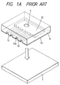
- Figs. 1A and 1B are respectively a schematic exploded perspective view and a schematic perspective after bonding showing an example of the liquid jet recording head of this type of the prior art.
- 1 is a first substrate comprising Si, etc., comprising a group of electricity-heater converters and wiring portions thereof provided as the energy generating element for generating the energy to be utilized for discharging liquid on its upper surface.
- 8 is a second substrate, having an introducing inlet 9 for liquid for recording such as ink (hereinafter merely called as "ink"), a groove 11A for forming an ink flow channel 11 corresponding to the electricity heat converter, an ink flow channel wall 10 and a concavity 12 which becomes the common liquid chamber for storing ink and also communicating it to the respective flow channels formed thereon.
- ink ink
- the first and the second substrates are mutually adhered and fixed with an adhesive 13 to assemble a recording head as shown in Fig. 1B.
- the head obtained by the method as described above has the problem that the straight forward progress of the ink droplets is impaired. This is, above all, due to the fact that the orifices, which are formed of materials of different qualities, cause difference in wettability with the ink at the peripherals of orifices.
- the step of bonding an orifice plate is included during its preparation, and it is necessary to perform strictly registration between the orifice and the flow channel portion during said bonding. Also, since said bonding can be done with difficulty when the end surfaces of the first and the second substrate to be bonded to the orifice plate are not coincident in plane, difficulty can also ensue during adhesion of the both substrates for this reason.
- the orifice plate is also adhered by use of an adhesive, but since the pitch of the flow channel 11 and the height of the flow channel wall 10 are fine to the extent of about some 10 ⁇ m, unless the coated amount (thickness) of the adhesive layer 13 is controlled to about some ⁇ m, the adhesive may come out to the flow channel side because of the pressure applied during bonding, whereby there may be caused such fear that the low channel diameter or the discharging orifice diameter may be varied, even to leading to clogging. Also, when the adhesive force is not sufficient, there is the fear that peeling of the orifice plate may occur.
- the resin film has generally a thickness of about 20 to 50 ⁇ m, not only handling is cumbersome, but also it may be considered that wrinkles may be formed or bubbles may be introduced during plastering to effect no good plastering.
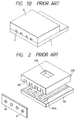
- the ink jet recording head is constituted of an orifice plate 40 having orifices 41 as the discharging outlet, a ceiling plate 400 having ink channel grooves 401 communicated to the respective orifices, and a heater board 100A constituting a part of the ink channel and having energy generating elements 101 for generating energy to be utilized for discharging ink, as shown in Fig. 2.
- the orifice plate is provided for the purpose of constituting the discharging outlet surface of the same member in order to prevent slippage in the discharging direction of discharged ink droplet caused by the difference in wettability between the heater board and the ceiling plate, and also the orifice, including its shape, etc. is an important element influencing the discharging performance of the ink jet recording head.
- the orifice through the ink is discharged becomes the most important portion, and with high developments of the image recording technique and the recording head production technique in recent years as described above, the orifice size (orifice diameter) has become miniaturized and a plurality of orifices have become provided at high density.
- the recording technique at the present time demands higher precision and higher speed as a matter of course, and along with this demand, the dimension of the orifice of the ink jet recording head has been miniaturized, and the orifice density high, and yet the head has become to have a plurality of orifices.
- the preparation steps from photolithography to plating are long, and also auxiliary materials such as substrate and resist, etc. must be employed.
- the ink jet recording head is constituted of an orifice plate, a ceiling plate and a substrate as described above.
- orifices and ink channels communicated thereto when no correctly registered in their positions, will badly affect discharging performance, even causing non-discharging in the worst case.
- the main body of the ink jet recording head comprised of, for example as shown in Fig. 2, the orifice plate 40 having the orifice 41 (discharge plate), the ceiling plate for forming the ink liquid path communicated with each orifice, and the base member constituting a part of the path 401 and having the electro-mechanical converting element 101A for generating energy used for discharging the ink.
- the orifice plate has a fine orifice for discharging the ink, which orifice has great significance affecting the discharge character of the ink jet recording head.
- the metallic plate of SnS, Ni, Cr, Al, and resin film material such as polyimide (PI), polyethersulfone (PES) polyetheretherketone (PEEK), and polyester (PE) which can be formed easily in predetermined thickness and in low cost can be used.
- resin film material such as polyimide (PI), polyethersulfone (PES) polyetheretherketone (PEEK), and polyester (PE) which can be formed easily in predetermined thickness and in low cost can be used.
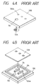
- the recording head with the constitution shown in Fig. 3 has a constitution obtained by providing, for example, an ink channel wall 7A comprising a cured film of a photosensitive resin, etc. as shown in Fig. 3B and an outer frame 8 constituting liquid chamber, etc. on a substrate 100 comprising a glass, etc. having an energy generating member 101A for generating the energy to be utilized for discharging ink such as a heat generating element, a piezoelectric element, etc. as shown in Fig.
- the recording head with the constitution shown in Fig. 4A has a constitution obtained by forming a main recording head portion provided with an ink channel wall 7A, comprising, for example, a cured resin film of a photosensitive resin, etc. and an outer frame 8A, as shown in Fig. 4B on a substrate 100 comprising a glass, etc. having an ink discharging energy generating member 101A generating energy used for discharging ink such as heat-generating element, piezoelectric element, etc. as shown in Fig. 4A, and bonding a discharging orifice plate 12A to the upper part thereof in predetermined positional relationship.
- the constitution of the discharging orifice plate for constituting the ink jet recording head with the constitution as described above and the characteristics to ink have great influences on the recording characteristics of the ink jet recording head such as the discharging direction of ink, the amount of the ink discharged, etc., and various investigations have been done in the prior art about the material to be used for formation of the discharging material and its structure.
- the problems to be solved may include the following problems.
- the ink jet head to be applied to the ink jet recording device is provided generally with an ink energy discharging member, ink channels, ink discharging orifices and a liquid chamber of ink.
- the ink jet prepared according to the method of the prior art as described above has problems in preparation during bonding of the discharging orifice plate and during ink repellent treatment.
- a means of coating the plate back surface or the front surface of the ink channel with an adhesive and bonding the both is employed, but during coating of the adhesive, there ensues the problem that a part or all of the ink channel or the discharging orifice portion finely worked is filled with the adhesive.
- ink repellent treatment it is generally practiced to attach a fluorine type or silicon type thin film on the whole plate surface, and also at this time, the phenomenon of collapsing of hole similarly occurs as during coating of the adhesive as described above.
- electroforming or etching is expensive.
- an ink jet recording head having a discharging orifice plate formed with provision of thru-holes on a plate material has, for example, a representative constitution as shown in Fig. 5.
- a discharging orifice plate 40 having discharging orifices 41 communicated to the channel bonded to the opened face thereat a bonded body having a substrate 100 provided with an energy generating member 101A formed by wall member 7A for generating the energy to be utilized for discharging ink within the ink channel and a ceiling plate 11B bonded together.
- the structure of the discharging orifice structure and its characteristics to ink have great influences on the recording characteristics of an ink jet recording head such as the discharging direction of ink, the droplet amount of discharged ink, etc., and various investigations have been made in the prior art about the material to be used for formation of the discharging orifice plate and its structure.
- the treatment is required to be performed so that the water repellent treatment may not be extended to the inner surface of the discharging orifice which is demanded to be inkphillic.
- the water repellent treatment of the outer surface of the discharging orifice in the prior art has been performed by forming a thin layer of an ink repellent surface treating agent on the surface of a transfer member and transferring the thin layer onto the surface having the discharging orifice of the ink jet recording head.
- the method of the prior art have involved such problems that the treatment working is cumbersome, and also that the water repellent agent may be progressed to the inner portion of the discharging orifice, transfer cannot be sufficiently effected or even water repellent surface can not be formed because of deterioration of the transfer member.
- ink jet recording head is generally equipped with fine ink discharging orifice, ink channel and ink discharging energy generating element provided on a part of the ink channel.
- those channels are in most cases communicated to a common liquid chamber and constituted so that the recording liquid may be supplied smoothly and sufficiently into the liquid channels.
- the recording technique at the present time demands higher precision and higher speed as a matter of course, and according to such demands, the discharging orifices of the ink jet recording head became fine in dimension, higher in orifice density became higher, and also became to have a plurality of orifice groups.
- the pitch between the recording dots becomes narrower, and for making the fluid resistance through the ink path for higher speed, there is the demand to expand the pitch between orifices.
- Still another object is to provide a method for manufacturing an ink jet recording head having an ink path communicated with a discharge opening, a discharge every generating element disposed in said ink path, and a discharge opening plate provided with said discharge opening and attached to an end surface of said ink path, the ink being discharged from said discharge opening, characterized in that, said discharge opening is formed by irradiating an excimer laser light to said discharge opening plate.
- Still another object is to provide a method for manufacturing an ink jet recording head having an ink path communicated with a discharge opening, a discharge energy generating element disposed in said ink path, and a discharge opening plate provided with said discharge opening and attached to an end surface of said ink path, the ink being discharged from said discharge opening, characterized in that said discharge opening plate is attached to said end surface of ink path prior to said discharge opening is formed, and then an excimer laser light is irradiated to said discharge opening plate attached to form said discharge opening.
- Still another object is to provide a liquid discharge recording head, comprising, a first base plate provided with a discharge energy generating element, a second base plate formed by resin molding and is connected with said first base plate, said second base plate having a groove for forming a liquid flow path corresponding to location of said discharge energy generating element upon said connection, and being provided with said liquid discharge opening for recording before said groove, said second base plate having a member for forming said discharge opening whose thickness is selected thinner at least a portion at which said discharge opening is formed.
- Still another object is to provide a method for manufacturing a liquid jet recording head made by connecting a first base plate provided with discharge energy generating means and a second base plate for forming a liquid flow path for recording corresponding to location of said discharge energy generating means, characterized in that, said discharge opening is formed by irradiating an excimer laser light to a blank of second base plate made of resin to which a plate member for forming a liquid discharge opening for the recording is attached integrally.
- Still another object is to provide a method for manufacturing an ink jet recording head having an ink path communicated with a discharge opening, discharge energy generating element disposed in said ink path for generating energy used for discharging the ink, and a discharge opening forming member provided with said discharge opening and attached to an open surface at which an opening communicated with said ink path is disposed, the ink being discharged through said discharge opening to carry out the recording, characterized in that, said discharge opening on said discharge opening forming member is formed by irradiation of an excimer laser light, and said excimer laser entering side upon said irradiation is attached to said open surface.
- Still another object is to provide a method for manufacturing an ink jet recording head having a base plate provided with a element generating discharge energy used for discharging the ink, a ceiling plate having a recessed portion for forming an ink flow path corresponding to disposed location of said discharge energy element by being attached with said base plate, and a discharge opening forming member on which a discharge opening communicated with said ink path, and discharges the ink is formed, characterized in that, an excimer laser light is irradiated from said recessed side to form said discharge opening, after said ceiling plate and discharge opening forming member are connected integrally.
- Still another object is to provide an ink jet recording head having a discharge opening forming member provided with a discharge opening for dischargeing ink, an ink path communicated with said discharge opening, and a discharge energy generating element disposed on a part of said ink flow path to generate energy used for discharging the ink, the ink being discharged to carry out recording, characterized in that, said discharge opening forming member is formed by accumulating plural members of different kind materials.
- Still another object is to provide a discharge opening plate for an ink jet recording head, comprising, a plate member, a water repellant cover layer provided on an upper surface of said plate member, an adhesive layer provided on a lower surface of said plate member, and a through hole for forming a discharge opening for discharging ink therethrough being provided.
- Still another object is to provide a method for manufacturing a discharge opening plate for an ink jet recording head, comprising, a step for providing said water repellant cover layer on an upper surface of plate member, a step for providing said adhesive agent layer on a lower surface of plate member, a step for drilling a thorugh hole on a plate member on which said both layers are provided for forming a discharge opening for discharging the ink.
- Still another object is to provide a method for manufacturing an ink jet recording head, characterized in that, drilling a plate-like member made by accumulating a water repellant layer, a base film and an adhesive agent layer sequencially, and adhering said plate-like member to a surface on which an opening communicating with an ink path of a head body.
- Still another object is to provide a method for manufacturing an ink jet recording head, characterized in that, drilling a plate-like member made by accumulating a water repellant layer, a base film, an adhesive agent layer and a mold release film sequentially, tearing said mold release film, and adhering said plate-like member whose mold release film has been torn to a surface on which an opening communicating with an ink path of a head body.
- Still another object is to provide a method for manufacturing a discharge opening plate having a through hole for forming a discharge opening, for an ink jet recording head, comprising, a step for forming a metallic layer forming said discharge opening plate at a surface of a base member on which a resin layer having configuration corresponding to that of said through hole is arranged corresponding to arrangement of said through hole, a step for making water repellant treatment to a surface of said metallic surface, and a step for removing said resin layer from said surface of base member to form said through hole.
- Still another object is to provide a method for manufacturing an ink jet recording head made by connecting a plate having grooves for forming ink paths provided corresponding to each of plural ink discharge openings, and a base plate having a discharge energy generating element disposed at a part of said ink paths, comprising, said grooves of plate are formed by irradiating an excimer laser light.
- Still another object is to provide a method for manufacturing an ink jet recording head made by connecting a plate having grooves for forming ink paths provided corresponding to each of plural discharge openings and a common liquid chamber for storing the ink supplied to said ink paths, and a base member having a discharge energy generating element disposed at a part of said ink paths, characterized in that, forming a base member having said grooves for forming said common chamber by injection molding, working said grooves forming said ink paths by irradiating an excimer laser light to said base member.
- Still another object is to provide a method for manufacturing an ink jet recording head in which plural discharge openings are formed by irradiating excimer laser light, characterized in that, at least one of entering angles of the laser light relative to a surface of said discharge openings is differentiated from others.
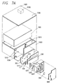
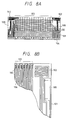
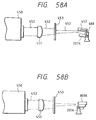
- Figs. 7A and 7B show respectively schematic disassembled view and assembled view of a ink jet recording head according to an example of the present invention in which an ink housing portion which is an ink feeding source is made integral to give a disposable type.
- numeral 100 is a heater board comprising an electricity heat convertor (discharging heater) and a wiring of A1, etc. for feeding power thereto formed by film forming technique on a Si substrate, which corresponds to the first substrate 1 in Fig. 9. Its detailed constitution is described below by referring to Fig. 8.
- 200 is a wiring substrate corresponding to the heater board 100, and the corresponding wiring is connected by, for example, wire bonding.
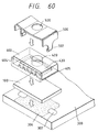
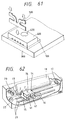
- this ceiling plate 400 is a ceiling plate provided with a partition wall, a common liquid chamber for limiting the ink flow channel, which corresponds to the second substrate 8 in Fig. 1 and in this embodiment is comprises a resin material having integrally an orifice plate portion.
- This ceiling plate 400 is described below by referring to Figs. 39 to 41.
- the 300 is a support made of, for example, a metal, 500 is a pressing spring, and by engaging the both under the state with the heater board 100 and the ceiling plate 400 sandwiched therebetween, the heater board 100 and the ceiling 400 are pressure fixed by the urging force of the pressing spring 500.
- the support 300 as well as the wiring substrate 200 can be provided by plastering, etc., and also can be made to have the mounting standard onto the carriage for performing scanning of the head. Also, the support 300 also functions as the member which cools the heater board 100 by release of the heat generated with driving.
- 600 is a feeding tank, which receives ink feed from the ink reservoir portion forming the ink feeding source, and functions as a subtank leading the ink to the common liquid chamber formed by bonding of the heater board 100 and the ceiling plate 400.
- 700 is a filter arranged at a site in the feeding tank 600 near the ink feeding inlet to the common liquid chamber, and 800 is a lid member of the feeding tank 600.
- 900 is an absorber for impregnation of ink, and is arranged within the cartridge main body 1000.
- 1200 is a feeding inlet for feeding ink to the unit comprising the respective portions 100 - 800 as described above, and by injecting ink through the feeding inlet 1200 in the step prior to arrangement of said unit to the portion 1010 of the cartridge main body 1000, ink can be impregnated into the absorber 900.
- 1100 is a lid member of the cartridge main body, and 1400 is an air communicating opening provided at the lid member for communication to the air.
- 1300 is a liquid repellant material arranged inwardly of the air communicating opening 1400 by which the ink leak through the air communicating opening 1400 can be prevented.
- the unit comprising the respective portions 100 - 800 is arranged by registration at the portion 1010. Registration or fixing at this time can be effected by, for example, fitting the projection 1012 provided on the cartridge main body 1000 with the hole 312 provided on the support 300 corresponding thereto, whereby the cartridge shown in Fig. 7B is completed.
- the ink is fed into the feeding tank 600 from the cartridge inner portion through the feeding inlet 1200, the hole 320 provided at the support 300 and the introducing inlet provided on the back side in Fig. 7A of the feeding tank 600, and after passing through the inner portion thereof, flows from the discharging outlet into the common liquid chamber through an appropriate feeding pipe and the ink introducing inlet 420 of the ceiling plate 400.
- the connecting portion for ink communication as described above, for example, packing of silicone rubber, butyl rubber, etc. is provided, whereby sealing is effected to ensure the ink feeding flow channel.
- Figs. 8A and 8B are a plan view of the heater board 100 according to this example and its partial enlarged view.
- Fig. 8A 101 is the heater board substrate according to this embodiment, and 103 the discharging heater portion.
- 104 is a terminal, which is bonded by wire bonding to the outside.
- 102 is a temperature sensor, which is formed at the discharging heater portion 3, etc. according to the same film forming process as for the discharging heater portion 103, etc.
- Fig. 8B is an enlarged view of the portion B including the sensor 102 in Fig. 8A, 105 and 106 are respectively discharging heater and wiring.
- 108 is a heater for heating the head.
- the sensor 102 is formed according to the same film forming process as information of semiconductors similarly as other portions, and therefore extremely high in precision, and can be formed of a material varying in electroconductivity depending on temperature such as aluminum, titanium, tantalum, tantalum pentoxide, niobium, etc. which is the constituent material of other portions.
- titanium is a material which can be arranged between the both for enhancing adhesiveness between the heat-generating resistance layer constitutes the electricity-heat converting element and the electrode
- tantalum is a material which can be arranged at the upper portion for enhancing the cavitation resistance of the protective layer on the heat-generating resistant layer.
- line width is made bold, and for making the influence of wiring resistance, etc. smaller, a zig-zag shape is formed to make the resistance higher.
- the orifice plate should desirably have a thickness of about 10 to 50 ⁇ m, and also in view of the cost of material and ink resistance as the material of the orifice plate, film materials of thermoplastic resins, such as polyether ketone, polyimide, polyether sulfone, etc. may be included.
- a film of a polyether ether ketone (PEEK) with a thickness of 25 ⁇ m is used.
- the excimer laser is a laser capable of oscillating UV-ray and has such advantages as high strength, good monochromaticity, directional characteristic, capability of short pulse oscillaton, capability of making energy density very great by focusing with a lens.
- Exicimer laser is a device capable of oscillating UV-ray of short pulses (15 - 35 ns)by discharging excitation of a gaseous mixture of rare gas and halogen, and Kr-F, Xe-Cl, Ar-F laser are frequently used.
- the oscillation energy of these may be some 100 mJ/pulse, and the pulse repetition frequency 30 to 100 Hz.
- the short pulse UV-ray of high luminance such as the excimer laser
- the excimer laser is irradiated on a polymer resin surface
- the Ablative Photodecomposition (APD) process where the irradiated portion is decomposed and scattered momentarily with accompaniment of plasma emission and impact sound, by which process working of the polymer resin is rendered possible.
- metals such as SUS, etc., opaque ceramics, Si, etc. are not influenced by irradiation of excimer laser in an atmosphere of the air and hence can be used as the masking material in working by excimer laser.
- Fig. 9 is a schematic illustration of a device for performing working orifice by use of such excimer laser.
- 210 is an excimer laser
- 211 is a lens for focusing laser beam 212 emitted from the excimer laser 210
- 209 is a mask arranged between the excimer laser 210 and the orifice plate
- 240 is an orifice plate on which orifices are to be formed.
- Fig. 10 is a perspective view showing the details of the mask 209 and the orifice plate 240.
- On the mask 209 are provided transparent portions 291 corresponding to the sites where orifices on the orifice plate 240 are to be worked so that laser beam 212 may be transmitted therethrough.
- this pattern can be worked into the film for orifice plate.
- the number of the orifices is plural, but this is shown schematically and practically in this example a mask having orifices of 360 DPI ⁇ 33 ⁇ m linearly juxtaposed is used.
- orifices are formed by irradiation of laser beam 212 through the mask 209 on the plate 240.
- the mask material it should preferably receive no influence of the heat by laser irradiation, and, for example, a material with small coefficient of thermal expansion, such as a metal material of Be-Cu, etc, can be used.
- the orifice on the orifice plate prepared according to the method as described above is free from abnomal deformation at the peripheral portion of the orifice as in working by carbon dioxide laser and YAG laser, and a circular form similar to the mask is worked beautifully from the surface to the back of the film.
- Table 1 Design value ( ⁇ m) Dimension after laser working ( ⁇ m) Error ( ⁇ m) Pitch variance 70.5 70.4 - 0.1 Hole diameter 34.0 33.9 - 0.1
- the orifice working with excimer laser has sufficient precision for further improvement of the performance of the ink jet recording head, and also has a specific feature that it can be produced simply.
- Fig. 11 and Fig. 12 are respectively a schematic view and a perspective view representing the details of the mask and the orifice of the orifice working device.
- a glass material applied with grooving as the ceiling plate 400 and a heater board 100 having energy generating elements and wirings therefor, etc. provided on a Si wafer are bonded together, and then the bonded surface was subjected to ozone washing of the orifice plate 40, the ceiling plate 400 and the heater board 100, followed by coating of a silane coupling agent.
- a dry film As the material of the orifice plate 40 after peel off of the protective film, polyether on one side is heated to about 40 - 80°C.
- the ceiling plate 400 and the heater board 100 integrally combined are also heated at the same time. This heating is performed by use of a hot plate or a clean oven in this example.
- the dry film surface of the film and the ceiling plate-heater board are pushed against each other under a pressure of 2 to 10 kg/cm2 for 1 to 10 seconds to be bonded together.
- the composite is cooled gradually to room temperature (about 25°C), followed by separation of the film from the ceiling-heater board.
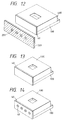
- the dry film which becomes the orifice plate is separated from the other protective film of Mylar film to be bonded to the ceiling-heater board to become the state shown in Fig. 13.
- UV-ray is irradiated on the bonded dry film surface to effect curing of the film, and the recording head (ceiling plate-heater board orifice plate) is fixed at a predetermined position comprising the constitution shown in Fig. 11, followed by registration of the recording head, the excimer laser and the mask. This registration is corresponded by making the stand 207 for filing the recording head movable system in this example.
- excimer laser light is irradiated on the orifice plate 240 through the mask 209 to effect working of the orifice 241.
- the state of the recording head after such wording is shown in Fig. 14.
- the orifice shape of the ink jet recording head in this example has been deemed to have desirably a shape which is narrower at the tip as nearer from the ink channel 402 toward the orifice 241.
- most of its shape have been columnar as shown in Fig. 16.
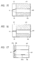
- Fig. 17 is a sectional view of an ink liquid channel of the ink jet recording head according to an another example of the present invention.
- 40a is one plate of the orifice plates comprising two kinds of materials
- 40b is the other orifice plate.
- a PI film with a thickness of about 20 ⁇ m is used, and as the material for the plate 40b, a dry film with a thickness of about 20 ⁇ m (SE-320, manufactured by Tokyo Ohka K.K.) for bonding the PI film 40a to the opening surface at which the openings of ink liquid channels are arranged.
- the PI film 40a is bonded to the dry film 40b before bonding to the opening surface of the ink liquid channels, but of course the PI film 40a may be also bonded after bonding of the dry film 40b to the opening surface. By such bonding, the main recording head becomes the state as shown in Fig. 18.
- orifices are worked by laser beam on the main recording head bonded with the orifice plate.
- an excimer laser is used.
- a mask 209 of SUS having a shape 291 of orifice to effect registration between the opening of the ink liquid channel and the orifice shape 291 of the mask 209
- an excimer laser beam is irradiated on the mask 209 for several seconds.
- the orifice places 40a, 40b at the portions irradiated with the excimer laser are removed to form the orifices 241.
- the range removed is varied depending on the material of the film orifices 241 with the shapes shown in Fig. 17 are obtained.
- the shape which becomes smaller in diameter toward the tip end shown in Fig. 17 has the effect of increased discharging speed and also the discharging direction which is made constant, leading to improvement of recorded image quality.
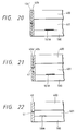
- Fig. 20 and Fig. 21 concern other examples of the present invention, showing similarly sectional views as in Fig. 17.
- the same shape of the ink liquid channel 401 and the same dry film for the material of the orifice plate 40b as in Fig. 17 are used.
- the orifice and the metal material 40a' formed are bonded to the opening of the ink liquid channel with registration. This state is shown in Fig. 20.
- the shape of the ink liquid channel and the orifice plate 40b are the same as in the example as described above, and as the material for the orifice plate 40a, films of Myler, Tedlar (registered brand), etc. are used.
- the film 40a is previously bonded to the plate 40b, and then bonded to the opening surface of the liquid channel. Thereafter, the orifice is worked with an excimer laser beam.
- the recording head obtained according to this Example has water repellency at the discharging orifice surface and the orifice plate, and therefore no unnecessary ink pooling or dew formation occurs at the discharging orifice surface, whereby stable discharging without influences from these is rendered possible.
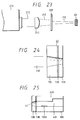
- Fig. 23 shows the manner in which orifice working is performed by excimer laser beam on the orifice plate made of a resin film according to another embodiment of the present invention, and the same elements as those shown in Fig. 29 are attached with the same symbols.
- Fig. 23 shows the manner in which orifice working is performed by excimer laser beam on the orifice plate made of a resin film according to another embodiment of the present invention, and the same elements as those shown in Fig. 29 are attached with the same symbols.
- 210 is a laser oscillating device for oscillating KrF excimer laser beam, 212 a pulse laser beam with a wavelength of 248 mm and a pulse width of about 15 nsec oscillated from the laser oscillating device 211, 211 a synthetic quartz lens for converging the laser beam 212, 209 a projection mask having aluminum capable of shielding the laser beam 212 vapor deposided thereon, on which a plurality of holes of 133 ⁇ m in diameter are arranged at a pitch of 212 ⁇ m to constitute an orifice pattern.
- PES 40 is an orifice plate member, which comprises a film of polyether sulfone (PES) having a thickness of 4 ⁇ m coated with a 6 ⁇ m thick tacky layer, and further plastered with a 25 ⁇ m thick Mylar.
- PES polyether sulfone
- Fig. 24 is an enlarged sectional view of the orifice plate member 40 shown in Fig. 23, and in Fig. 24, 12B is a PES film forming the orifice plate, 13B a tacky layer as the adhesive, and 178 a Mylar.
- 12B is a PES film forming the orifice plate, 13B a tacky layer as the adhesive, and 178 a Mylar.
- orifices of 3 ⁇ m are formed at a pitch of 70 ⁇ m.
- the orifice plate 12B obtained by peel-off of the Mylar 17B is bonded to the opened face of the ink channel to complete the main ink jet recording head.
- Fig. 25 is a sectional view of the main recording head thus obtained.
- the shape obtained by this example becomes tapered, being widened in the direction opposite to the discharging direction. With such shape, the discharging speed and the ink amount discharged are increased stably to give the result that quality of the recorded image is improved.
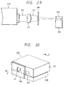
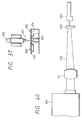
- Fig. 26 is an enlarged views of the portion where the laser beam 212 is incident on the film, and in Fig. 26, 18B is a dry film forming the orifice plate, 19B a protective film comprising a polyether and 20B a Mylar.
- the orifice plate of the dry film obtained by peel-off of the protective film 19B is bonded to the opened face of the ink channel (Fig. 27).
- the Mylar is peeled off to form the state shown in Figs 28, and UV-ray is irradiated on the orifice plate 18B of the bonded dry film from the discharging direction side to effect photocuring, thereby completing the main ink jet recording head. Also according to this example, a shape with the taper of the orifice being widened in the direction opposite to the ink discharging direction is obtained.
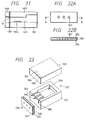
- Figs. 30 and 31 show detail of a main body 205 of the ink jet recording head in which a orifice is formed by causing the laser beam 212 oscilated from laser device 210 of Fig. 29 to enter from an orifice forming surface side of the body 205, among which Fig. 30 is an enlarged view of the head body (each members are shown so as to the separated slightly for simplicity), Fig. 31 is a cross section thereof.
- 207 is a ceiling plate provided with grooves for forming the groove discharging the ink
- 208 is a base plate provided with patterning of the discharge energy generating element
- 209 is an opening communicated with the ink path
- 10B is an orifice plate made of resin film
- 41 is an orifice formed on the orifice plate 10B.
- 13B is an adhesive agent for adhering the orifice plate 10B to an opened surface at which the opening of ink path
- 401 is an ink path
- 101A is an electro-mechanical converting element as discharge energy generating element.
- the orifice work according to mere excimer laser, orifice portion may have tapered configuration whose discharge opening side is flared.
- the orifice may have convergent configuration, it is possible to obtain the amount of ink liquid droplet necessary for recording and the discharge speed, to recording image in high quality can be realized.
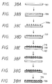
- a liquid repellent (ink repellent) coating layer 303 and an adhesive layer 304 are provided on one surface of a plate member 302 capable of forming a discharging orifice plate.
- a liquid repellent (ink repellent) coating layer 303 and an adhesive layer 304 are provided on one surface of a plate member 302 capable of forming a discharging orifice plate.
- the plate member 302 one comprising a resin, a metal, etc. can be utilized.
- the resin to be used for the plate member in the case of using a thermosetting resin for the adhesive layer 304 it is preferable to use a resin having high heat resistance which will not give rise to deformation, etc. during heat curing of the adhesive layer 304, such as polyimide, polyether sulfone, polysulfone, polyester, acrylic resin, phenol resin, urea resin, melamine resin, epoxy resin, silicone resin, etc.
- a resin having high heat resistance which will not give rise to deformation, etc. during heat curing of the adhesive layer 304 such as polyimide, polyether sulfone, polysulfone, polyester, acrylic resin, phenol resin, urea resin, melamine resin, epoxy resin, silicone resin, etc.
- the resin plate member may be also improved in strength and other characteristics by addition of various additives or fillers into the resin.
- a plate member made of a metal for example, a plate member comprising stainless steel, nickel, gold, silver, platinum, etc. can be utilized.
- Said plate member should be conveniently thin in its thickness for the purpose of inhibiting flash or residue during formation of thru-holes for formation of discharging outlets as described below to the extent which gives no bad influence on ink discharging, or for the purpose of performing continuous perforation but for the balance with the strength, it should desirably have a thickness within the range from 5 to 100 ⁇ m.
- the liquid repellent coating layer 303 may be formed of any material provided that it has sufficient adhesion characteristic with the plate member 302, and also has liquid repellency to the extent that it repells aqueous ink to be used for recording and the ink does not remain as droplet by attachment on the surface and, for example, can be formed of a material suitably selected from the materials known as conventional liquid repellent treating agents. Also, during formation of such coating layer, the layer thickness or other forming conditions may be suitably set so that good liquid repellent characteristic at the discharging outlet surface may be obtained.
- the adhesive layer 304 may be formed of a material suitably selected which can give good bonded sate between the discharging orifice plate and the main recording head portion and, for example, an epoxy type adhesive subjected to B staging by the heating treatment under the conditions of 100 °C - 120 °C for 30 to 60 minutes, etc. can be utilized, and provided to a layer thickness of about 1 to 5 ⁇ m.
- liquid repellent coating layer 303 and the adhesive layer 304 for example, there can be utilized, for example, the dipping method, the coating method, the printing method, the spraying method, the method of transferring the liquid repellent coating layer or the adhesive layer to a predetermined portion, etc.
- a thru-hole 301 is opened at a predetermined portion of the plate member 302 having the liquid repellent coating layer 303 and the adhesive layer 304 provided thereon as described above.
- the press working method For formation of the thru-hole 301, the press working method, the electron beam working method, the laser beam working method, the liquid jet working method, etc. can be utilized.
- the plate member 302 By combining the plate member 302 with the above-mentioned constitution with these methods, perforation working of high precision perforation working can be done at high speed and simply.
- the discharging orifice plate formed as described above is tentatively bonded by superposing with registration on a predetermined position of the main recording head portion having flow channel walls, etc. with the constitution as shown in Fig. 3 and Fig. 4 provided on a substrate through, for example, the adhesive layer 304 subjected to B staging, then subjected to the heating treatment under the condition of 150 to 200 °C for 30 to 120 minutes to completely cure the adhesive layer 304 subjected to B staging to effect bonding these, whereby the recording head of the present invention can be obtained.
- an epoxy type adhesive comprising a mixture of various components shown below was coated according to the spin coating method under various conditions shown below, further subjected to the heating treatment under the conditions of 100 °C to 120 °C, and 30 to 60 minutes, followed by drying and solification to effect B staging, to give a number of plate materials attached with adhesive layers.
- the layer thickness of the adhesive layer after B staging was found to be 1 to 5 ⁇ m.
- Adhesive layer composition (1) Mixture of Epikote 1004 (trade name) and methyl ethyl ketone formulated at 2 : 1 (weight ratio) 100 parts by weight (2) Mixture of dicyandiamide and dimethylformamide formulated at 1 : 4 (weight ratio) 3 parts by weight (3) N,N-dimethylbenzylamide 0.2 parts by weight Spin coating conditions: rotational number: 500 - 1000 rpm time: 5 - 10 sec.
- a solution prepared by adding a fluorine silicon coating agent KP - 801 (trade name, manufactured by Shinetsu Kagaku Kogyo) to 0.07 % by weight into Difreon S-3 (trade name, manufactured by Daikin Kogyo) was spin coated under the various conditions shown below, and then subjected to the heating treatment of 80 °C to 120 °C form a liquid repellent coating layer of 1 ⁇ m or less.
- the thus obtained discharging orifice plate was tentatively adhered with registration at the predetermined positions shown respectively on the main recording head portion having flow channel walls, etc. on a substrate with the constitution shown in Fig. 3 and Fig. 4 through its adhesive layer, and then the adhesive layer of the discharging orifice plate was completely cured by the heating treatment at 150 °C to 200 °C for 30 to 120 minutes, to complete a recording head.
- the main recording head portion to be used in this Example one conventionally used in this field was used. Also, the ink discharging energy generating member, the electrical system for applying discharging signals on said generating member, etc. were formed by utilizing the materials conventionally used in this field.
- a discharging orifice plate was obtained in the same manner as in Example a except for using a stainless steel plate with a thickness of 50 ⁇ m as the plate material, and forming perforation of thru-holes by the continuous perforation working with electron beam.
- the discharging orifice plate obtained was found to have good quality similarly as in Example a.
- thru-holes were provided with the same sizes and the arrangements as in Example 1 according to the continuous performation working method by a press.
- each discharging rifice plate of the main recording head portion used in Example a (with the constitution shown in Fig. 3 and Fig. 4) is pressed under a load of about 2 kg/cm2 against the two-liquid mixed epoxy resin adhesive layer on the silicone rubber obtained by the above operation, and then the silicon rubber was peeled off to have the adhesive layer onto the main recording head.
- the discharging orifice plate previously obtained was tentatively adhered with registration onto the transfer adhesive layer thus obtained, and then subjected to the heating treatment at 60 °C to 100 °C for 30 minutes to 60 minutes to cure the adhesive.
- Example a the fluorine silicone coating agent solution used in Example a was spin coated uniformly on a silicone rubber with a thickness of 0.5 mm under the conditions shown below.
- the silicone rubber was peeled off to have the fluorine silicone coating agent layer transferred onto the discharging orifice plate surface of the main recording head, followed further by curing by heating at 80 °C - 120 °C, to complete a recording head.
- a recording head was prepared in the same manner as in Comparative example a except for using a stainless steel plate with a thickness of 50 ⁇ m as the plate material, and the same one as used in Example b as the main recording head.
- each 50 of recording heads prepared in respective examples were used.
- Table 2 Example a Example b Comparative example a Comparative example b Discharging plate bonding 100% 100% 88% 94% Ink repellent treatment 91% 89% Initial printing 100% 100% 95% 95% Prolonged printing 100% 100% 95% 98%
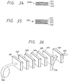
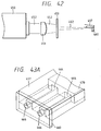
- the ink jet liquid has grooves which become ink channels 505 and ink liquid chamber 506 on an appropriate substrate 501 such as glass, metal, plastic, etc., and further has a energy generating member 504 for generating energy to be utilized for discharging ink such as heat energy, etc. on the lower side of another substrate 502 along the groove formed along the substrate 501, followed by bonding of the substrate 501 and the substrate 502 to prepare a main head 507.
- the discharging orifice plate 503 which is a plate body of a multilayer structure applied with high precision hole opening by press working is adhered to the surface of the main head 507 where openings communicated to the ink channels 505 are formed.
- this case is formed of a plate body 520A comprising the three layers having an ink repellent layer 531, a base film 532 and an adhesive layer 533 successively laminated, and after the plate body 520A is subjected to hole opening by press working, it is adhered as the discharging orifice plate 503 with the adhesive layer 533 onto the main head 507.
- this case is formed of a plate body 530 comprising four layers having an ink repellent layer 531, a base film 532, an adhesive layer 533 and a release film 534 successively formed, and after the plate body 530 is subjected to hole opening by press working, it is adhered as the discharging orifice plate 503 by peeling the release film 534 with the adhesive layer 533 onto the main head 507.
- non-stretched film such as polyether ether ketone (PEEK), polyether sulfone (PES), polysulfone (PSF), polyethylene terephthalate (PET), polyimide, etc.
- PEEK polyether ether ketone
- PES polyether sulfone
- PSF polysulfone
- PET polyethylene terephthalate
- PEEK polyether ether ketone
- the nonstretched film of 25 ⁇ polyether ether ketone (PEEK) is sufficiently satisfactory in precision with a heat shrinkage of 0.1 % or less after held at 150 °C for 4 hours.
- the preparation steps of the plate body 530 comprise the 7 steps of the film washing step 601, the ink repellent treatment agent coating step 602, the drying step 603, the surface modification step 604, the adhesive coating step 605, the drying step 606 and the release film molding step 607.
- the points of the present embodiment are the ink repellent treatment and the adhesive coating, and therefore other steps are omitted.
- ink repellent treatment agent coating step 602 it has been practiced in the prior art to effect the water repellent treatment after hole working, whereby there may be occurred clogging of hole with the ink repellent treatment agent. This problem can be improved by applying this step to the base film 532.
- fluorine type or silicon type agents such as Fluorocoat of Asahi Glass, LF-40 of Soken Kagaku, DEFENSA-7702 (trade name) of Dainippon Ink Kagaku, etc. may be employed.
- DEFENSA-7702 is coated by a roll coater.
- the base film 532 as described above is excellent in chemical resistance and therefore adhesion strength between the adhesive and the base film 532 cannot but become weak.
- surface modification of the base film 532 is effected in the surface modification step 604.
- the plasma treatment, the uv/O3 treatment, etc. are effective.
- the uv/O3 treatment method was employed. Evaluation of surface modification was performed in terms of contact angle. By irradiation of a light of 2537 ⁇ at 20 mw/cm2 for 5 minutes, the initial contact angle 36° could be improved to 31 with polyether ether ketone (PEEK).
- PEEK polyether ether ketone
- epoxy type uv curable adhesives acrylic uv curable adhesive, etc. may be included.
- a stock solution of a dry film is coated by roll coating and vacuum dried.
- the release film plastering step 607 is not required if the above characteristic 1 of the adhesive layer 533 being initially smooth is complete, but practically more or less stickiness may sometimes remain, and therefore in view of easiness during the press working in the later step, a release film 534 may be laminated.
- a release film 534 may be laminated.
- the release paper polyethylene (PE), polyvinyl fluoride (PVF), etc. are suitable.
- the plate body 530 obtained according to the steps as described above, the item of clogging of holes with adhesive, ink repellent treatment agent which is the problem of the prior art has been solved.
- it can be accomplished by deleting the release film plastering step 607 in Fig. 36.
- hole opening for forming ink discharging orifices is performed by applying press working on the plate body 530 obtained according to the steps as described above.
- the plate body 530 is mounted on the delivery table 604 and the die 655 of a press hole opening device as shown in Fig. 37, fixed with the film press 653, and holes are opened by driving the punch 651 by the punch driving source 652.
- the discharging orifice diameter is made 3.2 ⁇ and the pitch 70.5 ⁇ .
- punching sag, burr are generated, but in this example, the influence is made null by making the punching sag an adhesive, and further generation of the burr could be inhibited by controlling the clearance of the die 652 of the punch 651 to about 1 ⁇ .
- a highly precise ink jet head can be obtained by forming ink discharging orifices by press working of a plate body with a multilayer structure.
- the metal layer 709 as described below is demanded to have high uniformity, smoothness, etc.
- Formation of the resin layer pattern 708a can be performed by laminating a photosensitive resin layer 708 on the surface of the substrate 707 as shown in Fig. 38B, then exposing the photosensitive resin layer 708 through a desired pattern to light, or spot irradiating the photosensitive resin layer 708 in a desired pattern, and developing the photosensitive resin layer 708 after exposure, thereby leaving the pattern of the resin layer 708a to remain on the substrate surface.
- the method utilizing photolithography as described above is not limitative, but other various methods can be used.
- a metal layer 709 which is the constituent material of the discharging orifice plate is formed by electroforming, and then water repellent treatment is applied on the metal layer 709 surface as shown in Fig. 38E to form the layer 710 of water repellent treatment agent.
- a material having necessary rigidity and satisfactory characteristics to ink may be suitably selected and used for the discharging orifice plate.
- nickel, etc. can be utilized.
- the conditions for obtaining good water repellent treatment effect may be set.
- the metal layer 709 is peeled off from the surface of the substrate 707 to provide a metal plate (Fig. 38F).
- the resin 708a is treated with an appropriate liquid for dissolution and removal thereof to remove the resin 708a from the metal plate 709, thereby forming a void portion (thru-hole) for forming the discharging orifice from which the resin 708a, is withdrawn to obtain a discharging orifice plate (Fig. 38H).
- the method for applying the water repellent treatment agent onto the metal layer 709 surface and forming the adhesive layer 711 other than the coating method as described above, there can be utilized the method in which the metal layer is peeled off previously from the substrate to be taken out as the plate before performing the water repellent treatment, one surface of said plate is sprayed with the water repellent treatment agent, while the other surface with an adhesive (711) either with a time difference or simultaneously; the method in which a water repellent treatment agent layer formed on an appropriate base material such as Mylar film, etc. is superposed on one surface of said plate, pressed with rollers, etc., and further a water repellent treatment agent formed on an appropriate base material such as Mylar film, etc.
- the discharging orifice plate thus obtained has one surface subjected to the water repellent treatment and the other surface having an adhesive layer which can be utilized for bonding to a bonding member having liquid channels, etc. formed thereon which becomes the ink passage for formation of ink jet recording head.
- the water repellent treatment will not extend to the portion which becomes the orifice inner surface. Besides, due to the presence of the resin 708, formation of the adhesive layer 711 can be done more easily.
- a dry film (Laminate HG, manufactured by Dinachem) was laminated and pattern exposure and developing processing were applied on said laminate film (thickness 25 ⁇ m) to form spot-like resin layers arranged corresponding to the arrangements of the discharging orifices.
- nickel plating was effected on the spot-like resin layer formed surfaces on the electroconductive substrate to form a nickel plated layer (thickness 20 ⁇ m).
- a solution of a fluorosilicon type KP-801 (trade name) manufactured by Shinetsu Kagaku as the water repellent agent dissolved at a ratio of 0.01 % by weight dissolved in Difreon S3 (trade name, manufactured by Daikin Kogyo) was prepared, coated on the nickel plated layer surface on the electroconductive substrate by the spin coating method, followed by drying of the coated layer (thickness 1 ⁇ m or less) by the heating treatment under the conditions of 150 °C, 2 hours, to effect the water repellent treatment.
- the electroconductive substrate and the nickel plated layer were peeled off to give a nickel plate.
- an adhesive Takelite xP-405/xH-8901b, manufactured by Takeda Seiyaku
- an adhesive layer thickness 2 ⁇ m
- a Mylar film was laminated on said adhesive layer, followed by treatment with an aqueous 3 - 4 % sodium hydroxide solution and removal of the dry film from the nickel plate, to give a discharging orifice plate.
- the Mylar film on the discharging orifice plate obtained was peeled off to have the adhesive layer exposed, and bonded to the main recording head portion having an energy generating member generating energy used for ink discharging, a discharging signal applying means onto the energy generating member, ink channels, etc. formed on a substrate as shown in Fig. 5 to prepare an ink jet recording head.
- the slippage angle from the predetermined discharging direction is 1° at the maximum, and also no nondischarging occurred because there was no progress of the water repellent into the inner portion of the discharging orifice.
- discharging was performed for a long time, there was no unnecessary pooling of ink on the surface, whereby stable discharging could be persisted.
- Example c After a discharging orifice plate was obtained in the same manner as in Example c except for using the product obtained by sputtering an aluminum coating layer on a Si substrate surface as the substrate for formation of the discharging orifice plate, an ink jet recording head was prepared.
- the heater 108 can be formed by use of the same material as the heat generating resistance layer of the discharging heater 105 (e.g. HfB2), it may be also formed by use of other materials constituting the heater board, such as aluminum, tantalum, titanium, etc.
- Fig. 39 shows a constitutional example of the ceiling plate material for constituting the ceiling plate 400 according to another embodiment.
- the ceiling plate material 400' is made to have a desired number of ink channel grooves 411, 412, ... (two in the Figure for brevity) and an orifice plate portion 404 provided integrally.
- the ceiling plate material 400' is simultaneously molded integrally together with the orifice plate portion 404 by use of a resin excellent ink resistance such as polysulfone, polyethersulfone, polyphenyleneoxide, polypropylene, etc.
- the orifice plate portion 404 may be also formed of the same resin material as the main body portion of the ceiling plate material 400' or another kind of resin material, which may be prepared separated from the main portion of the ceiling plate material 400' and inserted into the mold for insert molding.
- the resin can be molded with a mold having a reverse pattern thereto formed by such method as cutting, etc., whereby the flow channel grooves 411, 412 can be formed on the ceiling plate 400.
- the orifice plate 404 having thus integrally molded has a thickness of about 50 to 100 ⁇ m in molding. Although the orifice can be also formed under this state, but practically the flow channel length of that portion should be desirably 20 ⁇ m or less. This is because, if the flow channel length from the discharge heater 101A is large, discharging performance is influenced thereby. Accordingly, in this example, particularly the portion over the range where orifices to be formed are arranged corresponding to the grooves 411, 412 of the orifice plate portion 404 is worked to be made thin before formation of the orifices. In this example, excimer laser was used for working.
- Fig. 40 is a schematic illustration of a device for performing working by use of such excimer laser.
- 450 is an excimer laser oscillator (in this exmaple, it is made a Kr-F excimer laser oscillator)
- 451 is a lens of, for example, f value of 500 mm for converging laser beam 452.
- 453 is a mask comprising a plate of Al, etc. with a thickness of, for exmaple, 1 mm having a hole pattern corresponding to the worked portion.
- the ceiling plate material 400' is arranged adequately so that the surface to be worked may be irradiated by laser beam through the lens 451 and the mask 453.
- the laser beam emitted from the Kr-F excimer laser oscillator 450 is irradiated on the orifice plate 404 through the mask 453 having a hold of, for example, rectangular shape formed thereon.
- the orifice plate 404 becomes thin by working only of the portion where irradiated with excimer laser.
- Fig. 41A exhibits such state, where 465 is the grooved portion made thin by said working. At this time by controlling adequately the strength of laser and the working time, the thickness of that portion could be made about 10 to 20 ⁇ m.
- the orifice plate 404 is subjected to the liquid repellant treatment, because the surface having liquid repellancy has the effect to wetting of unnecessary ink, etc.
- the liquid repellant DEFENSA from Dainippon Ink diluted with Difreon S-3 from Daikin to 1 % is coated.
- UV-ray irradiation is effected.
- orifices corresponding to flow channels are formed by working with excimer laser. This can be done by replacing the mask having formed the holes corresponding to the orifices with the above mask in Fig. 40. After replacement, registration is effected, lowered by irradiation of laser to form orifices 406. Thus, the ceiling plate 400 as shown in Fig. 41B can be received. In Fig. 41B, for brevity, 4 orifices (or flow channels) are provided.
- grooves 411, 412 for flow channel formation and the common liquid chamber portion may be also worked with excimer laser, or these may be also worked after formation of the discharging outlet (orifice) portions. Also, when the length of the flow channel length in front of the discharging heater poses no problem, the orifice plate portion 404 is not necessarily made thin depending on the constitution.
- the heater board 100 is abutted against the orifice plate 404 as shown by the chain line to be bonded thereto, thereby giving a main recording head.
- the position can be determined of the flow channel direction by abutting the heater board 100 against the end surface on the opposite side to the end surface on the discharging side of the orifice plate portion 404 during bonding of the heater board 100 and the ceiling plate 400 integrally made with the orifice plate portion 404, the whole registration step and assembling step can be made easier. In addition, there is also no fear of peel-off of the orifice plate as in the prior art.
- Fig. 42 shows another embodiment of the present invention in which orifice working is performed by excimer laser beam on the orifice plate formed integrally with the ceiling plate, and the same elements as those shown in Fig. 40 are attached with the same symbols.
- 450 is a laser oscillating device for oscillating KrF excimer laser beam, 452 a pulse laser beam with a wavelength of 248 mm and a pulse width of about 15 nsec oscillated from the laser oscillating device 451, 453 a synthetic quartz lens for converging the laser beam 452, 454 a projection mask having aluminum capable of shielding the laser beam 452 vapor deposited thereon, on which a plurality of holes of 133 ⁇ m in diameter are arranged at a pitch of 212 ⁇ m to constituted an orifice pattern.
- Fig. 43A shows a constitutional example of the ceiling plate 457 according to this example.
- the ceiling plate 457 is made to have a desired number of ink channel grooves 464 and ink discharging orifices 466 formed on the orifice plate 460 corresponding thereto (two in the Figure for brevity) and an orifice plate portion 10 provided integrally.
- the ceiling plate material 457 is simultaneously molded integrally together with the orifice plate 460 by use of a resin excellent in ink resistance such as polysulfone, polyethersulfone, polyphenyleneoxide, polypropylene, etc.
- a resin can be molded with a mold having a fine groove of reverse pattern thereto by such method as cutting, etc., and with the use of the mold, liquid channel groove 464 can be formed on the ceiling plate 457.
- orifice within the mold, molding is effected under the state having no orifice 466 and excimer laser beam is irradiated by a laser device on the positions where orifices are to be formed from the ink channel side on the orifice plate 10 as explained in Fig. 42, followed by removal and evaporation of the resin, to form orifices 466.
- Fig. 43B The details of orifice formation are shown in Fig. 43B.
- the excimer laser beam 452 is irradiated on the orifice plate 460 through the mask 454 as described above from the ink channel side 464.
- the cross-sectional area of the orifice having a tapered shape becomes reduced toward the discharging direction.
- Fig. 44 is a perspective view of the main recording head constituted by bonding of the heater board 458 and the ceiling plate 457 as described above.
- the heater board 458 having the discharging heater 101A, etc. is bonded to the orifice plate 460 to obtain the main recording head.
- the position can be determined of the flow channel direction by abutting the heater board 458 against the end surface on the opposite side to the end surface on the discharging side of the orifice plate 460 during bonding of the heater board 458 and the ceiling plate 460 integrally made with the orifice plate 460, the whole registration step and assembling step can be made easier. In addition, there is also no fear of peel-off of the orifice plate as in the prior art.
- Figs. 46A and 46B show another example of the present invention, and are repsectively a perspective view and a sectional view of a ceiling plate having an orifice plate integral formed therewith.
- This example has made the irradiation angle, namely ⁇ 2 as described above 45° corresponding to the shapes of the ceiling plate and the orifice plate.
- irradiation angle namely ⁇ 2 as described above 45° corresponding to the shapes of the ceiling plate and the orifice plate.
- the discharging speed is increased to two-fold or more, and consequently the shooting position precision of droplet can be improved to give good recording result.
- the volume of discharged liquid is understood to become larger, and this gives better result to the recording density.
- the orifice plate and the ceiling are integrally combined, but application of the present invention is not limited thereto, but the desired effect can be of course obtained by bonding separately to the ceiling plate, and then applying the orifice working as described above thereon.
- Fig. 47 is a perspective view showing one example of ceiling plate 400 shown in Fig. 7, representing the groove 403 for common liquid chamber and the groove 402 (dotted line) for ink channel, and the ceiling plate 400 is a resin molding.
- the resin material polyether sulfone, polyether ether ketone excellent in ink resistance can be used. Molding of the ceiling plate 400 is performed by use of a commercially available injection molding machine and a mold forming a pair with the shape shown in Fig. 47.
- the excimer laser used in this example is KrF excimer laser and also Arf excimer laser can be used.
- the mask material a quartz substrate is used and the opaque portion 714 of the mask 453 is formed by Cr vapor deposition.
- the width 703 of the ink channel groove is made 32 ⁇ m corresponding to the constitution having 16 discharging outlets per 1 mm, and width 704 of the non-groove portion is made 31.5 ⁇ m.
- the resin molding shown in Fig. 47 becomes the ceiling plate having fine grooves for ink channel integrally as shown in Fig. 48.
- the ceiling plate 400 after being precisely washed is bonded to the heater board 100 having energy generating elements 101A such as heat generating elements, etc. arranged on a substrate which can be formed of glass, ceramics, Si, plastic, or metal, etc. as shown in Fig. 51 to constitute the main head 780.
- energy generating elements 101A such as heat generating elements, etc. arranged on a substrate which can be formed of glass, ceramics, Si, plastic, or metal, etc. as shown in Fig. 51 to constitute the main head 780.
- ink discharging outlet (orifice) in the main head 780 is ink discharging outlet (orifice) in the main head 780.
- Fig. 52 is a schematic view of an apparatus showing manufacturing manner of the orifice according to another embodiment.
- 450 is an excimer laser generating device
- 451 is a lens for collecting laser beams 452 outputted from the generating device 451
- 453 is a mask disposed between the generating device 450 and the orifice plate
- 40 is an orifice on which the orifice is formed
- 413 is a lens for collecting the laser beam for perforating the discharge opening on the orifice plate by projecting the mask 413.
- Fig. 53 is a perspective view for showing detail of the mask 453 and orifice plate 40.
- a transparent portion 91 is provided corresponding to a portion at which the orifice of orifice plate 40 is worked for causing the laser beam to transmit.
- the pattern provided on the mask 453 as the orifice will be worked on the film of orifice plate.
- the mask in which orifices of 360 DPI, ⁇ 33 ⁇ m are arranged side by side linearly is used.
- the laser beam 452 is irradiated to the plate 40 via the mask 453 to form the orifice. It is desirable for the mask not to be affected by heat due to laser irradiation, and for this reason material of low thermal coefficiency such as metal (for example Be-Cu) can be adopted.
- Fig. 54 and Fig. 55 show respectively a schematic illustration of a preferable orifice working device for practicing the method for preparing the recording head of the present invention and a perspective view representing the details of the mask and the orifice plate obtained by said preparation method.
- a glass material applied with grooving as the ceiling plate 400 and a heater board 100 having energy generating elements and wirings therefore, etc. provided on a Si wafer are bonded together, and then the bonded surface is subjected to ozone washing of the orifice plate 40, the ceiling plate 400 and the heater board 100, followed by coating of a silane coupling agent.
- a dry film (Tokyo Ohka K.K. Se-320) as the material of the orifice plate 40 after peel-off of the protective film, polyether on one side is heated to about 40 - 80 °C.
- the ceiling plate 400 and the heater board 100 integrally combined are also heated at the same time. This heating is performed by use of a hot plate or a clean oven in this example.
- the dry film surface of the film and the ceiling plate-heater board are pushed against each other under a pressure of 2 to 10 kg/cm2 for 1 to 10 seconds to be bonded together.
- the composite is cooled gradually to room temperature (about 25 °C), followed by separation of the film from the ceiling-heater board.
- the dry film which becomes the orifice plate is separated from the other protective film of Mylar film to be bonded to the ceiling-heater board.
- UV-ray is irradiated on the bonded dry film surface to effect curing of the film, and the recording head (ceiling plate-heater board-orifice plate) is fixed at a predetermined position comprising the constitution shown in Fig.
- the orifice shape of the ink jet recording head in this example has been deemed to have desirably a shape which is narrower at the tip as nearer from the ink channel 804 toward the orifice 805.
- most of its shape have been columnar.
- the principal part of the recording head prepared as described above is constituted as shown in Fig. 56.
- the angle ⁇ of the discharging orifice 805 formed on the orifice plate 802 differs for each liquid channel 804, whereby the droplet will fly with curving of the discharging direction 807 for each discharging orifice 805 in substantially the same angle as the discharging orifice angle.
- the recorded dot pitch d formed on the surface to be recorded 806 can be made smaller than the liquid channel pitch d' of the recording head.
- the discharging orifice width can be taken larger, and also it has become possible to take also larger width of the discharging energy element. For this reason, energy efficiency can be improved to enhance the discharging speed. Further, since the cross-sectional area of the liquid channel can be enlarged, supplement of ink to the liquid channel becomes smooth, and therefore response frequency can be also improved, and further overall improvement of image quality can be improved.
- the speed of the ink droplet discharged from the discharging orifice at the central portion with shorter flight length of the ink droplet can be made greater as compared with the speed of the ink droplet discharged from the discharging orifice at the outside portion with longer flight length of the ink droplet, and therefore the timings of the ink droplets shot finally onto the recording medium can be made the same very easily when the timings of the ink droplets discharged from the discharging orifices and their driving forces are the same for the respective discharging orifices.
- the discharging orifice angles of the respective discharging orifices are formed in the converging direction, but in the present invention, if necessary, the discharging angles can be set variously for the respective discharging orifices.
- the above-mentioned incident angle may be different from the angle formed between the plane which is vertical to the above-mentioned discharging orifice surface and formed between the direction in which above discharging orifices are juxtaposed and the direction in which the ink is discharged from the above discharging orifices, and the above discharging orifice surface.
- Fig. 57 is a schematic view of an ink jet recording head according to another example of the present invention, which head is disposable with an ink tank integrally combined.
- the ink jet recording head shown in Fig. 57 is provided with four main recording heads, each constituted by bonding a ceiling plate having a concavity (hereinafter called “groove") for constituting ink channels and common liquid chamber, and further a discharging orifice forming member (orifice plate) 802 integrally formed and a substrate (hereinafter called “heater board”) having an electricity-heat converter for generating discharging energy (hereinafter called “discharging heater”) and an Al wiring for supplying electrical signals thereto formed by the film forming technique on a Si substrate.
- a ceiling plate having a concavity (hereinafter called “groove) for constituting ink channels and common liquid chamber
- discharging orifice forming member 802 integrally formed and a substrate (hereinafter called “heater board”) having an electricity-heat converter for generating discharging energy (hereinafter called “discharging heater”) and an Al wiring for supplying electrical signals thereto formed by the film forming technique
- 600 is a sub-ink tank arranged adjacent to the main recording head, and the sub-ink tank 600 and the above main body are supported by lids 300 and 800.
- 1000 is a main cartridge and 1100 is the lid member of the main cartridge.
- Internally of the main cartridge is built in an ink tank, which supplies suitably ink to the sub-ink tank 600.
- Figs. 58A and 58B show the manner in which orifice working is performed by excimer laser beam on the orifice plate formed integrally with the ceiling plate. That is, Fig. 58A is a schematic view of the device in which the laser beam is incident so as to form discharging orifices from the ceiling concavity side, and Fig. 58B from the discharging orifice side.
- a laser oscillating device for oscillating KrF excimer laser beam
- 452 a pulse laser beam with a wavelength of 248 mm and a pulse width of about 15 nsec oscillated from the laser oscillating device 450
- 451 a synthetic quartz lens for converging the laser beam 452
- 453 a projection mask having aluminum capable of shielding the laser beam 452 vapor deposited thereon, on which a plurality of holes of 133 ⁇ m in diameter are arranged at a pitch of 212 ⁇ m to constituted an orifice pattern.
- 460 is an orifice plate for forming the discharging orifices and 801A is an ink jet recording head, both of which is fixed on an implement 207A which can be freely rotated relative to the laser beam 452.
- the principal portion of the recording head prepared as described above has the constitution as shown in Fig. 59.
- the discharging angle ⁇ of the discharging orifice 909 formed on the orifice plate 902 differ for each head 901, and therefore the droplet will fly with the discharging direction 911 of each head being curved substantially the same as the discharging angle. Accordingly, the recording dot pitch d'' for each discharging orifice row formed on the surface to be recorded 210 can be made smaller than the distance d''' between the discharging orifice rows of the recording head.
- the distance between the respective discharging orifice rows is the same as the recording dot row distance, greater memory size is required for taking timing for each recording dot row, but in the present invention, the distance between the recorded dot rows can be taken smaller, whereby the cost of the main printer can be made lower.
- such constitution is very effective in the case of color printing where the discharging orifice rows must be divided corresponding to the respective colors.
- Fig. 60 shows an embodiment which bonds or fixes the heater board 100 and the ceiling plate 400.
- the orifice plate portion 404 of the ceiling plate 400 is shown by the chain line, and showing of the wiring pattern on the heater board 100 is omitted.
- the registration of the heater board 100 and the ceiling plate 400 is performed by abutting the end surface of the heater board 100 against the orifice plate portion 404, and in bonding of these, the adhesive 405 was coated along the 3 sides of the peripheral portion of the ceiling plate 400. By doing so, flowing of the adhesive into the ink flow channel could be inhibited. Further, it is also possible to permit an adhesive to exist over a suitable range in necessary and sufficient amount at the bonding surface between the heater board 100 and the orifice plate 404.
- a photocurable type adhesive UV-201 (Grace Japan K.K.) is used, and after registration cured by irradiation with UV-ray of, for example, 10 - 30 J/cm2 to fix the both.
- UV-ray of, for example, 10 - 30 J/cm2
- the main recording head obtained by integration of the ceiling plate 400 and the heater board 100 in this way is fixed onto the support 300 by use of an adhesive 306.
- the adhesive 306 for example, HP2R/2H manufactured by Canon Chemical K.K. can be employed.
- both the substrates are adhered only at the peripheral portions other than the flow channel portion as described above, and no sufficient adhesion is obtained. Accordingly, an urging force of the pressing spring 500 is permitted to act from the upper side of the ceiling plate 400.
- the pressing spring 500 can be formed by use of, for example, phosphorous bronze or stainless steel for spring. By fitting the nails 507 provided at the lower portions of both ends into the hole portions 307 provided at the support 300 to thereby engaging the both, mechanical pressure is applied from the upper portion of the ceiling plate 400. In this way, sufficient adhesion state between the both substrates can be obtained.
- 520 is a hole which receives insertion of the feeding pipe for connecting the ink introducing inlet 420 of the ceiling plate 400 to the ink feeding inlet on the feeding tank 600 side.
- a photocurable type adhesive in bonding of the ceiling plate 400 with the heater board 100, a photocurable type adhesive is used, but its form may be any desired one or no adhesive may be required to be used, if sufficient fixing force or adhesion force can be obtained with the pressing spring 500.
- a suitable sealing material namely a sealing member such as sealant or rubber packing, etc. can be used.
- no adhesive 306 may be employed.
- the coating step of the adhesive can be simplified. Also when slippage occurred during registration in the prior art, there was a fear of sticking of adhesive to the flow channel portion at the discharging heater 105, etc. of the heater board 100, or occurrence of defective product by clogging of the flow channel or discharging outlet with adhesive, but no such phenomenon occurs in this example, and registration can be done for many times. Further, presence of more or less deformation, warping or variance in product in the ceiling plate by use of a resin material is permissible and therefore the manufacturing steps can become simple.
- Fig. 61 is a modification example of the constitution shown in Fig. 60. In this Figure, showing of the orifice plate 404 in the ceiling plate 400 is omitted.
- the structure is made to obtain sufficient adhesion by applying pressure with a plate spring 500 in flat shape from the upper surface of the ceiling plate 400 under the state where the main recording head comprising the heater board 100 and the ceiling plate 400 is bonded to the support 300.
- the plate spring 500 is further pressurized by another member of the upper part (e.g. feeding tank 600 in Fig. 7).
- the cartridge as shown in Fig. 7B can be obtained and further an ink jet printer as shown in Fig. 62, namely an ink jet printer by use of a disposable cartridge can be constituted by use of this.
- Fig. 62 14 is the cartridge shown in Figs. 7A and 7B, the cartridge 14 is fixed on the carriage 15 by a pressing member 41, and these are made reciprocally movable in the lengthy direction along the shaft 21. Also, registration relative to the carriage 15 can be effected by, for example, the hole provided on the support 300 and the dowel provided on the carriage 15 side. Further electrical connection may be obtained by joining of the connector on the carriage 15 to the connecting pad provided on the wiring substrate 200.
- This ink discharged by the recording head reaches a recording medium 18 with the recording surface regulated by a platen 9 to form an image on the recording medium 18.
- the cartridge 14 can be provided in one or plural number (two in the Figure) corresponding to the ink colors, etc. used.
- 17 is a carriage motor for scanning the carriage 15 along the shaft 21, 22 is a wire for transmitting the driving force of the motor 17 to the carriage 15.
- 20 is a feed motor jointed with the platen roller 19 for conveying the recording medium 18.
- the cartridge 14 is changed when there is no ink impregnated in the absorber 900, etc., and for that purpose, the cartridge 14 is desired to be low in cost. Since the cartridge 14 as described in the above examples can be produced by simple production steps and also with small number of steps, and therefore it can be constituted at low cost and is extremely suitable for disposable construction. Further, registration in assembling of the main recording head can be done correctly, and yet there occurs no variance in dimension or clogging of the flow channel, etc. by flowing of the adhesive, reliability is very high and also yield can be improved.
- the present invention is not limited to the examples as described above, but various constitutions can be employed as a matter of course.
- the main recording head the ink supplying source, etc. are made integral and disposable, but the both may be separate bodies, and each is not necessarily required to be made disposable. This is because, even the main recording head may be the fixed type without the condition of simple exchange, simple and inexpensive constitution as described above will also constitute to the reduction in cost of the main printer.
- ink flow channels and concavity for formation of the common liquid chamber are provided only on the ceiling plate side in the above examples, but these can be also provided on both thereof.
- discharging heater 105 is used so as to make the heat energy discharging energy in the above examples, an electricity-mechanical converting element which is deformed corresponding to current passage may be used to utilize the mechanical vibration as the discharging energy.
- the orifice plate portion 404 itself is made a constitution having the abutting portion against the heater board, but the shape, etc. of the abutting portion may be any desired one.
- such abutting portion may be also provided in the side surface direction so as to effect registration in the lateral direction, or in place of providing such abutting portion, the registration may be made through the combination of dowel and hole.
- the ceiling plate may be in the form having the wall portion with the same surface as the bonding surface in front of the groove portion and having the discharging outlet formed thereat.
- the ceiling plate and the heater board are adhered and bonded with a pressing spring, but if there is no problem in use only of an adhesive during said bonding, it is also possible to use a constitution without use of a pressing spring.
- the present invention brings about excellent effects particularly in a recording head, recording device of the bubble jet system among the ink jet recording system.
- the on-demand type is effective because, by applying at least one driving signal which gives rapid temperature elevation exceeding nucleus boiling corresponding to the recording information on an electricity-heat convertors arranged corresponding to the sheets or liquid channels holding liquid (ink), heat energy is generated at the electricity-heat convertors to effect film boiling at the heat acting surface of the recording head, and consequently the bubbles within the liquid (ink) can be formed corresponding one by one to the driving signals.
- the constitution of the recording head in addition to the combination constitutions of discharging orifice, liquid channel, electricity-heat converter (linera liquid channel or right angle liquid channel) as disclosed in the above-mentioned respective specifications, the constitution by use of U.S. Patent 4,558,333, 4,459,600 disclosing the constitution having the heat acting portion arranged in the flexed region is also included in the present invention.
- the present invention can be also effectively made the constitution as disclosed in Japanese Patent Laid-Open Application No. 59-123670 which discloses the constitution using a slit common to a plurality of electricity-heat convertors as the discharging portion of the electricity-heat converter or Japanese Patent Laid-Open Application No. 59-138461 which discloses the constitution having the opening for absorbing pressure wave of heat energy correspondent to the discharging portion.
- the recording head of the full line type having a length corresponding to the maximum width of recording medium which can be recorded by the recording device
- either the constitution which satisfies its length by combination of a plurality of recording heads as disclosed in the above-mentioned specifications or the constitution as one recording head integrally formed may be used, and the present invention can exhibit the effects as described above further effectively.
- the present invention is effective for a recording head of the freely exchangeable chip type which enables electrical connection to the main device or supply of ink from the main device by being mounted on the main device, or for the case by use of a recording head of the cartridge type provided integrally on the recording head itself.
- a restoration means for the recording head, a preliminary auxiliary means, etc. provided as the constitution of the recording device of the present invention is preferable, because the effect of the present invention can be further stabilized.
- Specific examples of these may include, for the recording head, capping means, cleaning means, pressurization or aspiration means, electricity-heat convertors or another heating element or preliminary heating means according to a combination of these, and it is also effective for performing stable recording to perform preliminary mode which performs discharging separate from recording.
- the present invention is extremely effective for not only the recording mode only of a primary stream color such as black etc., but also a device equipped with at least one of plural different colors or full color by color mixing, whether the recording head may be either integrally constituted or combined in plural number.
- the cheap but reliable ink jet recording head can be obtained by the simple manufacturing process in the small number of process.
- the orifice on the orifice plate with high density, in high accuracy and under accurate positioning relative to the ink path or the like.
- the mask member properly, more small or fine plural orifices can be manufactured together, so the ink jet recording head can be manufactured simply and in low cost. Additionally, realization of high accuracy can improve character of the image to be recorded.
- the discharge opening can be worked into the configuration desirable for ink discharge, workability of the discharge opening can be improved, and occurrence of bad influence resulted from working of the discharge opening can be prevented.
- the discharge opening by only adding the conventional working of the discharge opening to the discharge opening forming member preformed the discharge quality is increased and bad influence due to water-repellent treatment or the like can be prevented.
- the ink jet recording head having tapered configuration whose cross-section decreases with respect to the discharge direction, which enables to stabilize the amount of ink droplet and the discharge speed necessary for recording.
- the discharge quality such as accuracy of adhering position and recording density is improved and the recording image at high quality can be obtained.
- the discharge opening plate is formed by providing the water repellent cover layer and adhesive agent layer onto the plate member on which no through hole for forming the discharge opening is formed, high or difficult technique which becomes necessary when forming these layers after formation of the through hole is not indispensable.
- the through hole can be worked with high yield and good workability.
- the through hole for the discharge opening is perforated after formation of the water repellent cover layer the material for the water repellent cover layer would not go into the through hole, thus occurrence of problem in the prior art can be prevented.
- the adhesive layer for attaching the discharge opening plate to the main body of recording head the plate can be attached to the main body by using the adhesive agent layer easily. There is no need for applying the adhesive agent onto the attaching surface of the main body. In connection therewith, since the adhesive agent layer is supplied to the periphery of the discharge opening, the problem occurred in the prior art can be prevented.
- the discharge opening plate having the water repellent cover layer and the adhesive layer can be obtained by simply and effective method. Furthermore, the both layers are disposed at the predetermined position in the predetermined condition accurately, thus entry of these layers into the discharge opening can be prevented. For this reason, in the recording head usings the discharge opening plate of the present invention, the manufacturing yield is improved, the poor ink discharge due to ink clogging at the discharge surface and connecting portion between the discharge opening plate and the main body of recording head would not occur. Thus, the proper printing character can be obtained, and reliability is increased. Furthermore, by carrying out sequence perforating after the adhesive agent layer and water repellent cover layer have been formed on for example the large plate, the treatment for each head which is effected in the prior art can be excluded. Thus, the process number in the discharge opening plate connecting process can be greatly decreased to thereby decrease the manufacturing cost of the recording head.
- the ink discharge opening is formed by press working, and the plate-like member is adhered to the surface on which the opening communicated with the ink path of the head body is formed by the adhesive agent layer, which enable to prevent occurrence of the clogging of ink discharge opening due to entry of the ink repellent treatment agent and adhesive agent and mass productivity will be increased. Furthermore, cheap ink jet head having high accuracy of ink discharge and the pitch of ink discharge opening can be manufactured.
- the water repellent treatment is made only to the portion which constructs outward wall surface of the discharge opening in the manufacturing process of the discharge opening plate, and because the through hole which forms the discharge opening upon water repellent treatment is filled with the resin and would not reach to the inner surface of the discharge opening, the water repellent treatment can be carried simply and effectively and accurately.
- the water repellent treatment of the outer surface of the discharge opening plate is carried out securely and effectively by simple method which adds the applying process of the water repellent treatment agent during the manufacturing process of the discharge opening plate, which enables to realize the discharge opening plate of high quality which has been made water repellent treatment in low cost.
- the ceiling plate in which the ink groove of fine configuration and the common chamber having several scores times of the ink path are integrally formed can be formed easily.
- high flatness of accuracy of the ink path can be realized by the working of excimer laser light.
- the process number can be decreased compared with the prior art, and the bad influence such as positioning shift, leakage of the recording liquid, flow-in of the adhesive agent into the ink path can be prevented.
- the ink jet recording head in which the ink discharge quality is increased can be obtained.
- the orifice plate can be provided with each discharge opening angle peculiar to the discharge opening in high density and high accuracy, and the positional relation between the ink path or the like and the orifice can be determined accurately.
- the discharge opening is formed obliquely on the orifice plate in high accuracy, and plural discharge openings (orifices) of different angle can be formed simultaneously on the plate.
- it is possilbe to form the discharge openings by changing or differenciating the discharge opening angle as the whole in every row of the discharging opening.
Abstract
Description
- The present invention relates to an ink jet recording head and manufacturing method thereof, in particular relates to recording head and manufacturing method thereof, and an ink jet recording apparatus.
- The present invention also relates to a discharge opening (orifice) plate and manufacturing method thereof, and an ink jet recording head with the plate, and an ink jet apparatus with the head.
- As the liquid jet recording device of this type of the prior art, there have been proposed various devices such as one in which fine droplets are discharged by generating pressure difference in the liquid channel through deformation of a piezoelectric element one in which a pair of electrodes are provided to deflect, or one in which droplets are discharged from the discharging orifices by utilizing heat energy such as by generating abruptly heat from the heat generating element arranged in the liquid channel, thereby generating bubbles, etc.
- Among them, the liquid jet recording head according to the system in which the recording liquid is discharged by utilizing heat energy is particularly attracting attention as one which is capable of recording of high resolving power because liquid discharging outlets such as orifices for formation of droplets for flying by discharging droplets for recording, etc., (hereinafter also called as "orifices") can be arranged at high density, can be made compact as a whole as the recording head, can fully utilize the recent technical progresses in the field of semiconductors as well as the advantages of IC technique and microworking technique of which improvements of reliability are marked, can be easily made lengthy and planar (dimensional), etc., whereby it can be easily made into multi-nozzle and armored at high density, and yet productivity during bulk production is good to make the production cost lower.
- Figs. 1A and 1B are respectively a schematic exploded perspective view and a schematic perspective after bonding showing an example of the liquid jet recording head of this type of the prior art.
- In these Figures, 1 is a first substrate comprising Si, etc., comprising a group of electricity-heater converters and wiring portions thereof provided as the energy generating element for generating the energy to be utilized for discharging liquid on its upper surface. 8 is a second substrate, having an introducing
inlet 9 for liquid for recording such as ink (hereinafter merely called as "ink"), agroove 11A for forming anink flow channel 11 corresponding to the electricity heat converter, an inkflow channel wall 10 and aconcavity 12 which becomes the common liquid chamber for storing ink and also communicating it to the respective flow channels formed thereon. - As shown in Fig. 1A, the first and the second substrates are mutually adhered and fixed with an
adhesive 13 to assemble a recording head as shown in Fig. 1B. - However, the head obtained by the method as described above has the problem that the straight forward progress of the ink droplets is impaired. This is, above all, due to the fact that the orifices, which are formed of materials of different qualities, cause difference in wettability with the ink at the peripherals of orifices. In the prior art, for the purpose of avoiding such problem, it has been proposed to prepare separately an orifice plate comprising orifices molded by etching of a metal plate or a photosensitive glass plate, or an orifice plate comprising orifices by hole working on a resin film, etc., and plastering it onto the main head.
- However, in the liquid recording head with such constitution (hereinafter also called "ink jet recording head" or merely "recording head"), there ensued the following problems.
- In the ink jet recording head as described above, the step of bonding an orifice plate is included during its preparation, and it is necessary to perform strictly registration between the orifice and the flow channel portion during said bonding. Also, since said bonding can be done with difficulty when the end surfaces of the first and the second substrate to be bonded to the orifice plate are not coincident in plane, difficulty can also ensue during adhesion of the both substrates for this reason.
- In addition, the orifice plate is also adhered by use of an adhesive, but since the pitch of the
flow channel 11 and the height of theflow channel wall 10 are fine to the extent of about some 10 µm, unless the coated amount (thickness) of theadhesive layer 13 is controlled to about some µm, the adhesive may come out to the flow channel side because of the pressure applied during bonding, whereby there may be caused such fear that the low channel diameter or the discharging orifice diameter may be varied, even to leading to clogging. Also, when the adhesive force is not sufficient, there is the fear that peeling of the orifice plate may occur. - Further, in the orifice plate by use of a resin film, because the resin film has generally a thickness of about 20 to 50 µm, not only handling is cumbersome, but also it may be considered that wrinkles may be formed or bubbles may be introduced during plastering to effect no good plastering.
- The complicatedness of the preparation steps and the large number of steps as described above bring about increase in the production cost of recording head, and this has been also a problem in making the recording head as described above, or the recording head constituted by integration with an ink tank, etc. which is the ink supplying source disposable.
- The contents as described above are to be described in more detail as follows. The ink jet recording head is constituted of an
orifice plate 40 havingorifices 41 as the discharging outlet, aceiling plate 400 havingink channel grooves 401 communicated to the respective orifices, and a heater board 100A constituting a part of the ink channel and havingenergy generating elements 101 for generating energy to be utilized for discharging ink, as shown in Fig. 2. - Generally speaking, the orifice plate is provided for the purpose of constituting the discharging outlet surface of the same member in order to prevent slippage in the discharging direction of discharged ink droplet caused by the difference in wettability between the heater board and the ceiling plate, and also the orifice, including its shape, etc. is an important element influencing the discharging performance of the ink jet recording head. Above all, the orifice through the ink is discharged becomes the most important portion, and with high developments of the image recording technique and the recording head production technique in recent years as described above, the orifice size (orifice diameter) has become miniaturized and a plurality of orifices have become provided at high density.
- On the other hand, various contrivances have been made in the prior art for working of orifice. Some examples are mentioned below:
- 1) mechanical working with drill;
- 2) fine working by discharging working;
- 3) fine working by anisotropic etching of Si;
- 4) the method by patterning according to photolithography and plating;
- 5) fine working with carbon dioxide, YAG laser, etc.
- However, as described above, the recording technique at the present time demands higher precision and higher speed as a matter of course, and along with this demand, the dimension of the orifice of the ink jet recording head has been miniaturized, and the orifice density high, and yet the head has become to have a plurality of orifices.
- In such point of view, according to the methods of prior art examples 1) and 2) as mentioned above, there were involved such problems that miniaturization of orifice dimension was difficult, and also that the efficiency was not good in working of a plurality of
- orifices of high density. On the other hand, in the method of 3), there was the problem that the cost of Si material for the orifice plate was high in cost, and the working time was long.
- Further, in the method of 4), the preparation steps from photolithography to plating are long, and also auxiliary materials such as substrate and resist, etc. must be employed.
- In addition, the method of 5) could not prepare a satisfactory orifice complying with the above demand for the reason as described below.
- Working by carbon dioxide laser and YAG laser was not sufficient in laser output, and both shape and precision of the orifice formed were not satisfactory. For example, the orifice formed by YAG laser is not circular in shape, and also foreign matters not sufficiently removed by laser are attached around the orifice. Also depending on the material and the thickness of the orifice plate, it also sometimes happened that no orifice, namely opening portion could be formed.
- Also, since working by carbon dioxide laser and YAG laser is done by working orifices one by one, it is time consuming for working of a plurality of orifices and not suitable for bulk productivity.
- Further, although a plurality of orifices must be correct in each positional precision, working was more difficult, because a movable portion for enabling also registration precisely was also required in working by carbon dioxide laser and YAG laser of the prior art.
- As described above, according to the methods of the prior art, the respective problems were involved in the above-mentioned demand, and they were not sufficiently satisfactory as the working method of orifices.
- On the other hand, recording by an ink jet recording head corresponds to higher precision, higher speed as described above, and improvement of its reliability has also become important. Accordingly, improvements have been also done to ink. As a consequence, since the material in contact with ink is demanded to have ink resistance performance, the material which becomes the orifice plate is also required to satisfy such demand. Therefore, orifice working may be sometimes difficult depending on its material.
- Also, the ink jet recording head is constituted of an orifice plate, a ceiling plate and a substrate as described above. Above all, orifices and ink channels communicated thereto, when no correctly registered in their positions, will badly affect discharging performance, even causing non-discharging in the worst case.
- However, since both orifices and ink channels are fine in their sizes and constituted at high densities, and therefore it is difficult to assemble with correct registration, thus posing a great problem in preparation of ink jet recording head.
- The above content can be explained below from different aspect.
- As mentioned above, the main body of the ink jet recording head comprised of, for example as shown in Fig. 2, the
orifice plate 40 having the orifice 41 (discharge plate), the ceiling plate for forming the ink liquid path communicated with each orifice, and the base member constituting a part of thepath 401 and having the electro-mechanical converting element 101A for generating energy used for discharging the ink. - The orifice plate has a fine orifice for discharging the ink, which orifice has great significance affecting the discharge character of the ink jet recording head. In detail, it is necessary for the orifice plate of the ink jet recording head to be excellent in workability since fine orifice is provided, and excellent in ink-proof character since it is directly contacted with the ink.
- Conventionally, the metallic plate of SnS, Ni, Cr, Al, and resin film material such as polyimide (PI), polyethersulfone (PES) polyetheretherketone (PEEK), and polyester (PE) which can be formed easily in predetermined thickness and in low cost can be used.
- On the other hahd, the recording of high speed and very fine has been required in these days as the progress of the recording technique, and for this reason the orifice is formed in small in diameter and with high density. Consequently, there have been adopted various kinds of working method for the orifice, among of which one using the laser light is used for orifice forming since it is suitable for fine working.
- However, it is very difficult to connect the perforated orifice plate and the corresponding ink liquid path, and positional shift or offset therebetween is generated to deteriorate the discharge quality as well as recording character. In addition, the adhesive used for connection might go into the liquid path due to positional shift.
- To add further, as the ink jet recording head utilizing a discharging orifice plate, for example, those with constitutions shown in Figs. 3A to 3C and Figs. 4A and 4B have been known.
- The recording head with the constitution shown in Fig. 3 has a constitution obtained by providing, for example, an
ink channel wall 7A comprising a cured film of a photosensitive resin, etc. as shown in Fig. 3B and anouter frame 8 constituting liquid chamber, etc. on asubstrate 100 comprising a glass, etc. having anenergy generating member 101A for generating the energy to be utilized for discharging ink such as a heat generating element, a piezoelectric element, etc. as shown in Fig. 3A, then bonding acover 11B for ink passages havingink feeding holes 9A thereto, further cutting the channel downstream portion of the bonded body obtained (the main recording head portion) along the line C - C to control the channel length, followed by bonding of a dischargingorifice plate 40 having thru-holes for formation of discharging orifices as shown in Fig. 3C to the channel opening end surface formed by said cutting in predetermined positional relationship. - On the other hand, the recording head with the constitution shown in Fig. 4A has a constitution obtained by forming a main recording head portion provided with an
ink channel wall 7A, comprising, for example, a cured resin film of a photosensitive resin, etc. and anouter frame 8A, as shown in Fig. 4B on asubstrate 100 comprising a glass, etc. having an ink dischargingenergy generating member 101A generating energy used for discharging ink such as heat-generating element, piezoelectric element, etc. as shown in Fig. 4A, and bonding a dischargingorifice plate 12A to the upper part thereof in predetermined positional relationship. - The constitution of the discharging orifice plate for constituting the ink jet recording head with the constitution as described above and the characteristics to ink have great influences on the recording characteristics of the ink jet recording head such as the discharging direction of ink, the amount of the ink discharged, etc., and various investigations have been done in the prior art about the material to be used for formation of the discharging material and its structure.
- Concerning the characteristics of the discharging plate in the prior art, the problems to be solved may include the following problems.
- a) In bonding between the discharging orifice plate and the main recording head portion, it is necessary to coat an adhesive on the bonding surface on the main portion side, but it is difficult to coat the adhesive uniformly, efficiently and with good workability onto the bonding surface on the main portion side, and yet the adhesive is liable to come around into the flow channel portion, whereby the production yield is low to be poor in bulk productivity.
Further, when coating of the adhesive is carried out so that the adhesive may not flow into the flow channel, the adhesive cannot be supplied to the peripheral portion of the flow channel in most cases, and if bonding is effected under such state with the discharging orifice plate, a gap will be formed between the discharging plate and the main portion, wherein ink may be pooled to cause readily interference with stable ink discharging. - b) In the case of providing a liquid repellent (ink repellent) coating layer for obtaining good ink discharged state on the surface of the discharging orifice plate which becomes the outer wall surface when bonded to the recording head (the surface on the side where ink is discharged, hereinafter called "discharging orifice surface"), it is difficult to coat uniformly the material for liquid repellent coating layer onto said surface, and also it is difficult to inhibit flowing of the material for formation of liquid repellent coating layer to the inner surface of the discharging orifice which is demanded to be inkphillic, whereby the product yield is low to be poor in productivity.
- Also, as described above, the ink jet head to be applied to the ink jet recording device is provided generally with an ink energy discharging member, ink channels, ink discharging orifices and a liquid chamber of ink.
- The output according to ink jet recording device is now demanded to be higher in resolving power and speed, and as the means for solving this, improvements of pitch precision and diameter precision of discharging orifice, and further ink repellent treatment in the vicinity of discharging orifice may be mentioned. For preparation of such ink jet head, there has been employed the method in which first fine grooves are formed on a substrate such as glass, metal, plastic, etc., the substrate is bonded to an appropriate plate to form liquid channels for ink within the head, and then a discharging orifice plate having holes, pitches precisely worked by electroforming, etching, etc. is bonded, followed by application of ink repellent treatment on the whole plate surface.
- The ink jet prepared according to the method of the prior art as described above has problems in preparation during bonding of the discharging orifice plate and during ink repellent treatment. In short, during bonding of the discharging orifice plate, generally a means of coating the plate back surface or the front surface of the ink channel with an adhesive and bonding the both is employed, but during coating of the adhesive, there ensues the problem that a part or all of the ink channel or the discharging orifice portion finely worked is filled with the adhesive. Further, during ink repellent treatment, it is generally practiced to attach a fluorine type or silicon type thin film on the whole plate surface, and also at this time, the phenomenon of collapsing of hole similarly occurs as during coating of the adhesive as described above. Also, in aspect of preparation cost, there is the problem that electroforming or etching is expensive.
- To say repeatedly, an ink jet recording head having a discharging orifice plate formed with provision of thru-holes on a plate material has, for example, a representative constitution as shown in Fig. 5.
- More specifically, it has a structure comprising a discharging
orifice plate 40 having dischargingorifices 41 communicated to the channel bonded to the opened face thereat a bonded body having asubstrate 100 provided with anenergy generating member 101A formed bywall member 7A for generating the energy to be utilized for discharging ink within the ink channel and aceiling plate 11B bonded together. - The structure of the discharging orifice structure and its characteristics to ink have great influences on the recording characteristics of an ink jet recording head such as the discharging direction of ink, the droplet amount of discharged ink, etc., and various investigations have been made in the prior art about the material to be used for formation of the discharging orifice plate and its structure.
- As the problem to be improved in the characteristics of the discharging orifice plate, there is the problem that when a light pool of ink is formed around the discharging orifice on the
outer wall surface 40a of the discharging orifice plate, disturbance is liable to occur in the discharging direction of ink as shown in Fig. 6B, whereby no stable ink discharging can be obtained (see Fig. 6A) and no good recording can be performed. - Moreover, when an ink attached film is formed on the whole surface around the discharging orifice, scattering of ink during ink discharging (splash phenomenon) occurs, whereby no stable recording can be performed, and the amount of the ink attached around the discharging orifice is further increased to develop and enlarge the ink pool. If the ink pool is excessively enlarged, ink discharging through the discharging orifice may sometimes become impossible.
- Accordingly, there has been known the method to prevent formation of such ink pool as described above onto the outer wall surface of the discharging orifice by applying water repellent treatment on the outer wall surface of the discharging orifice plate.
- In the water repellent treatment of the outer wall surface, the treatment is required to be performed so that the water repellent treatment may not be extended to the inner surface of the discharging orifice which is demanded to be inkphillic.
- The water repellent treatment of the outer surface of the discharging orifice in the prior art has been performed by forming a thin layer of an ink repellent surface treating agent on the surface of a transfer member and transferring the thin layer onto the surface having the discharging orifice of the ink jet recording head.
- Whereas, the method of the prior art have involved such problems that the treatment working is cumbersome, and also that the water repellent agent may be progressed to the inner portion of the discharging orifice, transfer cannot be sufficiently effected or even water repellent surface can not be formed because of deterioration of the transfer member.
- As described above, ink jet recording head is generally equipped with fine ink discharging orifice, ink channel and ink discharging energy generating element provided on a part of the ink channel.
- As the method for preparing such ink jet recording head, for example, there has been known the method in which fine groove is formed by cutting, etching, etc. on a substrate such as glass, metal, etc., and then the substrate having the groove formed thereon is bonded to another appropriate substrate to form ink channel within the head.
- In the case of having a plurality of ink channels, those channels are in most cases communicated to a common liquid chamber and constituted so that the recording liquid may be supplied smoothly and sufficiently into the liquid channels.
- Whereas, for supplying sufficient amount of recording liquid corresponding to the amount consumed by discharging of the liquid into the liquid channels, it is desirable to have a common liquid chamber of a volume with sufficient room relative to the amount consumed. However, with a common liquid chamber having a height virtually equal to the height of the ink channel, flow resistance of the recording liquid cannot be made substantially smaller, and therefore in spite of room in volume, no sufficient supply of the recording liquid can be done in some cases.
- Accordingly, it becomes the general constitution to make the height of the common liquid chamber sufficiently larger than the height of the liquid channel.
- However, in the method of forming fine grooves on a substrate such as glass or metal, it is difficult to form a common liquid chamber having a sufficient height relative to the height of ink channel.
- It is also possible to make the height of the common chamber greater by increasing the etching amount of the common liquid chamber by repeating etching for plural times, but this method increases the steps and therefore cannot be said to respond sufficiently to the demands for cost down or productivity.
- Accordingly, it has been practiced to prepare separately the common liquid chamber portion and bond the common liquid chamber portion to the end of the ink channel portion, thereby forming a desired common liquid chamber.
- According to this method, sufficient common liquid chamber volume can be obtained easily and therefore it is preferable in aspect of performance of the ink jet head.
- However, the method of bonding separately parts inherently has the problems of increase of number of steps, lowering in productivity, and there remain still points to be solved for accomplishing much cost down.
- Also, in the case of using such method, generation of stress or positional slippage accompanied with shrinkage by curing of the adhesive, leak of the recording liquid due to incomplete sealing, flowing of the adhesive into the liquid channel or into the common liquid chamber or clogging occurred in some cases.
- In addition, as described above, the recording technique at the present time demands higher precision and higher speed as a matter of course, and according to such demands, the discharging orifices of the ink jet recording head became fine in dimension, higher in orifice density became higher, and also became to have a plurality of orifice groups.
- Particularly, for higher densification, the pitch between the recording dots becomes narrower, and for making the fluid resistance through the ink path for higher speed, there is the demand to expand the pitch between orifices.
- For this purpose, by taking broad pitch between orifices and working the respective discharging orifices obliquely to form the discharging directions of the recording liquid so as to be convergent, it becomes possible to perform highly precise recording. However, according to the working method of the prior art, it has been difficult to perform working with delicate variances in the discharging angle for the respective orifices.
- Also, in a recording head having a plurality of the respective orifice rows for high speed recording or color recording, if the distance between the respective orifice rows is large, great memory size is required for adjusting the Dot signals between the respective orifice rows, thereby resulting in the cost-up of the main printer.
- It is an object of the present invention to overcome the defect in the prior art and to provide the ink jet recording head which can be manufactured through simple process and under little steps, and which is reliable and low in cost, and manufacturing method thereof.
- It is another object of the present invention to provide the orifice plate which has orifices arranged in high density and with high accuracy, and the ink jet recording head in which the relation between the orifice and ink path is accurately set and manufacturing method thereof, in view of the above mentioned problem relating to the orifice working and the connection of the orifice plate with the ceiling plate and heater board.
- It is still another object of the present invention to provide the ink jet recording head in which the discharge performance is increased by working the orifice onto the orifice plate comprised of plural kinds of materials.
- It is still another object of the present invention to provide the ink jet recording head which can obtain necessary ink droplet amount and discharge speed stably and sufficiently upon recording.
- It is still another object of the present invention to provide the discharge opening plate and ink jet recording head in which the water repellent cover layer is provided only at discharge opening surface and has adhesive layer for carrying out the adhering operation with the main body of the head easily, and can be mass producted with high yield, in view of the disadvantage in the ink jet recording head using the discharge opening plate.
- It is still another object of the present invention to provide the manufacturing method of the ink jet recording head which has high accurate diameter of the ink discharge opening and pitch, and which can be produced cheaply.
- It is still another object of the present invention to provide the method for carrying out the water repellent treatment only onto the outer wall surface of the discharge opening of the plate effectively.
- It is still another object of the present invention to provide the manufacturing method for the ink jet recording head which can solve the above mentioned various problem by forming the grooves for ink path by excimer laser after molding the ceiling plate having the groove for common chamber.
- It is still another object of the present invention to provide the ink jet recording head and manufacturing method thereof which has the orifice plate of high density and high accuracy, in which the discharge opening whose angle is changed in every discharge opening and in every head can be easily formed on the orifice plate, and in which relation between the orifice and the ink path are determined accurately.
- Still another object is to provide a method for manufacturing an ink jet recording head having an ink path communicated with a discharge opening, a discharge every generating element disposed in said ink path, and a discharge opening plate provided with said discharge opening and attached to an end surface of said ink path, the ink being discharged from said discharge opening, characterized in that, said discharge opening is formed by irradiating an excimer laser light to said discharge opening plate.
- Still another object is to provide a method for manufacturing an ink jet recording head having an ink path communicated with a discharge opening, a discharge energy generating element disposed in said ink path, and a discharge opening plate provided with said discharge opening and attached to an end surface of said ink path, the ink being discharged from said discharge opening, characterized in that said discharge opening plate is attached to said end surface of ink path prior to said discharge opening is formed, and then an excimer laser light is irradiated to said discharge opening plate attached to form said discharge opening.
- Still another object is to provide a liquid discharge recording head, comprising, a first base plate provided with a discharge energy generating element, a second base plate formed by resin molding and is connected with said first base plate, said second base plate having a groove for forming a liquid flow path corresponding to location of said discharge energy generating element upon said connection, and being provided with said liquid discharge opening for recording before said groove, said second base plate having a member for forming said discharge opening whose thickness is selected thinner at least a portion at which said discharge opening is formed.
- Still another object is to provide a method for manufacturing a liquid jet recording head made by connecting a first base plate provided with discharge energy generating means and a second base plate for forming a liquid flow path for recording corresponding to location of said discharge energy generating means, characterized in that, said discharge opening is formed by irradiating an excimer laser light to a blank of second base plate made of resin to which a plate member for forming a liquid discharge opening for the recording is attached integrally.
- Still another object is to provide a method for manufacturing an ink jet recording head having an ink path communicated with a discharge opening, discharge energy generating element disposed in said ink path for generating energy used for discharging the ink, and a discharge opening forming member provided with said discharge opening and attached to an open surface at which an opening communicated with said ink path is disposed, the ink being discharged through said discharge opening to carry out the recording, characterized in that, said discharge opening on said discharge opening forming member is formed by irradiation of an excimer laser light, and said excimer laser entering side upon said irradiation is attached to said open surface.
- Still another object is to provide a method for manufacturing an ink jet recording head having a base plate provided with a element generating discharge energy used for discharging the ink, a ceiling plate having a recessed portion for forming an ink flow path corresponding to disposed location of said discharge energy element by being attached with said base plate, and a discharge opening forming member on which a discharge opening communicated with said ink path, and discharges the ink is formed, characterized in that, an excimer laser light is irradiated from said recessed side to form said discharge opening, after said ceiling plate and discharge opening forming member are connected integrally.
- Still another object is to provide an ink jet recording head having a discharge opening forming member provided with a discharge opening for dischargeing ink, an ink path communicated with said discharge opening, and a discharge energy generating element disposed on a part of said ink flow path to generate energy used for discharging the ink, the ink being discharged to carry out recording, characterized in that, said discharge opening forming member is formed by accumulating plural members of different kind materials.
- Still another object is to provide a discharge opening plate for an ink jet recording head, comprising, a plate member, a water repellant cover layer provided on an upper surface of said plate member, an adhesive layer provided on a lower surface of said plate member, and a through hole for forming a discharge opening for discharging ink therethrough being provided.
- Still another object is to provide a method for manufacturing a discharge opening plate for an ink jet recording head, comprising, a step for providing said water repellant cover layer on an upper surface of plate member, a step for providing said adhesive agent layer on a lower surface of plate member, a step for drilling a thorugh hole on a plate member on which said both layers are provided for forming a discharge opening for discharging the ink.
- Still another object is to provide a method for manufacturing an ink jet recording head, characterized in that, drilling a plate-like member made by accumulating a water repellant layer, a base film and an adhesive agent layer sequencially, and adhering said plate-like member to a surface on which an opening communicating with an ink path of a head body.
- Still another object is to provide a method for manufacturing an ink jet recording head, characterized in that, drilling a plate-like member made by accumulating a water repellant layer, a base film, an adhesive agent layer and a mold release film sequentially, tearing said mold release film, and adhering said plate-like member whose mold release film has been torn to a surface on which an opening communicating with an ink path of a head body.
- Still another object is to provide a method for manufacturing a discharge opening plate having a through hole for forming a discharge opening, for an ink jet recording head, comprising, a step for forming a metallic layer forming said discharge opening plate at a surface of a base member on which a resin layer having configuration corresponding to that of said through hole is arranged corresponding to arrangement of said through hole, a step for making water repellant treatment to a surface of said metallic surface, and a step for removing said resin layer from said surface of base member to form said through hole.
- Still another object is to provide a method for manufacturing an ink jet recording head made by connecting a plate having grooves for forming ink paths provided corresponding to each of plural ink discharge openings, and a base plate having a discharge energy generating element disposed at a part of said ink paths, comprising, said grooves of plate are formed by irradiating an excimer laser light.
- Still another object is to provide a method for manufacturing an ink jet recording head made by connecting a plate having grooves for forming ink paths provided corresponding to each of plural discharge openings and a common liquid chamber for storing the ink supplied to said ink paths, and a base member having a discharge energy generating element disposed at a part of said ink paths, characterized in that, forming a base member having said grooves for forming said common chamber by injection molding, working said grooves forming said ink paths by irradiating an excimer laser light to said base member.
- Still another object is to provide a method for manufacturing an ink jet recording head in which plural discharge openings are formed by irradiating excimer laser light, characterized in that, at least one of entering angles of the laser light relative to a surface of said discharge openings is differentiated from others.
-
- Figs. 1A and 1B are views for explanating an assembly of conventional recording head;
- Fig. 2 is an exploded schematic view for showing construction of ink jet recording head;
- Figs. 3A to 3C and Figs. 4A and 4B are views of construction of ink jet recording head using discharge opening plate;
- Fig. 5 is an exploded perspective view showing main portion of ink jet recording head using discharge opening plate;
- Figs. 6A and 6B are partial cross sections for explaining ink discharge condition;
- Figs. 7A and 7B are respectively a exploded schematic view and a schematic view for explaining cartridge including recording head of the present invention;
- Figs. 8A and 8B are respectively plan view and partial enlarged view showing heater board applicable for recording head of present embodiment;
- Fig. 9 is a schematic view of apparatus according to one embodiment;
- Fig. 10 is a perspective view showing relation between mask and orifice plate;
- Fig. 11 is a schematic view of apparatus of another emobodiment;
- Fig. 12 is a perspective view showing relation between mask and recording head of Fig. 11;
- Fig. 13 is a perspective view showing condition in which film having no orifice is connected in manufacturing process of Fig. 11;
- Fig. 14 is a perspective view showing state in which orifice has been formed by excimer laser;
- Fig. 15 is a cross section of orifice according to another embodiment;
- Fig. 16 is a cross section of orifice according to conventional manufacturing method;
- Fig. 17 is a cross section of main body of recording head forming cartridge;
- Figs. 18 and 19 are schematic perspective views showing orifice manufacturing process of recording head body of Fig. 17;
- Figs. 20 and 21 are cross sections showing orifice manufacturing process according to another embodiment;
- Fig. 22 is a cross section showing one example of ink jet recording head;
- Fig. 23 is a schematic construction view of orifice working device using excimer laser light;
- Fig. 24 is a schematic view for manufacturing orifice plate of one emobodiment is manufactured;
- Fig. 25 is a cross section of orifice and ink path of ink jet recording head of one embodiment;
- Fig. 26 is a schematic view in which orifice plate used for another embodiment is formed;
- Fig. 27 is a cross section showing orifice manufacturing process according to the above embodiment;
- Fig. 28 is a cross section of orifice and ink path of above embodiment;
- Fig. 29 is a schematic construction view of orifice working device using excimer laser light;
- Fig. 30 is a schematic perspective view of main body having orifice of ink jet recording head;
- Fig. 31 is a cross section of main body having orifice of ink jet recording head;
- Fig. 32 is a view showing one embodiment of discharge opening plate, in which Fig. 32A is a plan view and Fig. 32B is a cross section along line A-A of Fig. 32A.
- Fig. 33 is a view showing construction of ink jet head manufactured by method of present invention;
- Figs. 34 and 35 are cross sections showing layer construction of plate-like member;
- Fig. 36 is a view showing manufaturing process of plate-like member;
- Fig. 37 is a front view of one embodiment of drilling device,
- Figs. 38A to 38H are process views for explaining main processes of mehtod of the present invention;
- Fig. 39 is a perspective view showing blank of ceiling plate used in the present embodiment;
- Fig. 40 is a view showing excimer laser device for forming orifice plate portion;
- Figs. 41A and 41B are views for explaining ceiling plate manufacturing process according to device of Fig. 40;
- Fig. 42 is a schematic view of orifice manufacturing device using excimer laser light;
- Figs. 43A and 43B are respectively a perspective view and a cross section of ceiling plate with which orifice plate of ink jet recording head is made integral;
- Fig. 44 is a perspective view of main body of ink jet recording head made by connecting heater board and ceiling plate of Fig. 43;
- Figs. 45A and 45B are respectively perspective view and cross section of ceiling plate with which orifice plate according to another embodiment is made integral;
- Fig. 46 is a cross section of one example of orifice;
- Fig. 47 is a perspective view of resin plate which has not been manufactured;
- Fig. 48 is a perspective view of ceiling plate which has been manufactured by present embodiment;
- Fig. 49 is a view for explaining removing work by excimer laser via mask;
- Fig. 50 is a schematic view of groove obtained work of Fig. 49;
- Fig. 51 is a schematic perspective view of main body of ink jet recording head obtained by using ceiling plate of embodiment;
- Fig. 52 is a schematic view of apparatus for manufacturing ink jet recording head of present invention;
- Fig. 53 is a perspective view showing mask and discharge opening forming member of Fig. 52;
- Fig. 54 is a schematic view of manufacturing device for discharge opening forming member suitable for carrying out manufacturing method of present invention;
- Fig. 55 is a perspective view showing mask and discharge opening forming member of Fig. 54;
- Fig. 56 is a schematic view illustrating by method of present invention;
- Fig. 57 is a perspective view of ink jet recording head of another embodiment of the present invention;
- Figs. 58A and 58B are respectively a schematic view illustrating device for entering laser beam to form discharge opening;
- Fig. 59 is a schematic explanation view for showing partial construction of ink jet recording head manufactured by present invention;
- Figs. 60 and 61 are views for explaining connected or assembled state of recording head body; and
- Fig. 62 is a perspective view showing one embodiment of ink jet printer constructed by using cartridge as shown in Fig. 7.
- The present invention is described in detail by referring to examples.
- Figs. 7A and 7B show respectively schematic disassembled view and assembled view of a ink jet recording head according to an example of the present invention in which an ink housing portion which is an ink feeding source is made integral to give a disposable type.
- In Fig. 7A, numeral 100 is a heater board comprising an electricity heat convertor (discharging heater) and a wiring of A1, etc. for feeding power thereto formed by film forming technique on a Si substrate, which corresponds to the
first substrate 1 in Fig. 9. Its detailed constitution is described below by referring to Fig. 8. 200 is a wiring substrate corresponding to theheater board 100, and the corresponding wiring is connected by, for example, wire bonding. - 400 is a ceiling plate provided with a partition wall, a common liquid chamber for limiting the ink flow channel, which corresponds to the
second substrate 8 in Fig. 1 and in this embodiment is comprises a resin material having integrally an orifice plate portion. The detailed one embodiment of thisceiling plate 400 is described below by referring to Figs. 39 to 41. - 300 is a support made of, for example, a metal, 500 is a pressing spring, and by engaging the both under the state with the
heater board 100 and theceiling plate 400 sandwiched therebetween, theheater board 100 and theceiling 400 are pressure fixed by the urging force of thepressing spring 500. One embodiment is described by referring to Figs. 62 and 63. Thesupport 300 as well as thewiring substrate 200 can be provided by plastering, etc., and also can be made to have the mounting standard onto the carriage for performing scanning of the head. Also, thesupport 300 also functions as the member which cools theheater board 100 by release of the heat generated with driving. - 600 is a feeding tank, which receives ink feed from the ink reservoir portion forming the ink feeding source, and functions as a subtank leading the ink to the common liquid chamber formed by bonding of the
heater board 100 and theceiling plate 400. 700 is a filter arranged at a site in thefeeding tank 600 near the ink feeding inlet to the common liquid chamber, and 800 is a lid member of thefeeding tank 600. - 900 is an absorber for impregnation of ink, and is arranged within the cartridge
main body 1000. 1200 is a feeding inlet for feeding ink to the unit comprising the respective portions 100 - 800 as described above, and by injecting ink through thefeeding inlet 1200 in the step prior to arrangement of said unit to theportion 1010 of the cartridgemain body 1000, ink can be impregnated into theabsorber 900. - 1100 is a lid member of the cartridge main body, and 1400 is an air communicating opening provided at the lid member for communication to the air. 1300 is a liquid repellant material arranged inwardly of the
air communicating opening 1400 by which the ink leak through theair communicating opening 1400 can be prevented. - On completion of ink filling through the
feeding inlet 1200, the unit comprising the respective portions 100 - 800 is arranged by registration at theportion 1010. Registration or fixing at this time can be effected by, for example, fitting theprojection 1012 provided on the cartridgemain body 1000 with thehole 312 provided on thesupport 300 corresponding thereto, whereby the cartridge shown in Fig. 7B is completed. - The ink is fed into the
feeding tank 600 from the cartridge inner portion through thefeeding inlet 1200, thehole 320 provided at thesupport 300 and the introducing inlet provided on the back side in Fig. 7A of thefeeding tank 600, and after passing through the inner portion thereof, flows from the discharging outlet into the common liquid chamber through an appropriate feeding pipe and theink introducing inlet 420 of theceiling plate 400. At the connecting portion for ink communication as described above, for example, packing of silicone rubber, butyl rubber, etc. is provided, whereby sealing is effected to ensure the ink feeding flow channel. - Figs. 8A and 8B are a plan view of the
heater board 100 according to this example and its partial enlarged view. - In Fig. 8A, 101 is the heater board substrate according to this embodiment, and 103 the discharging heater portion. 104 is a terminal, which is bonded by wire bonding to the outside. 102 is a temperature sensor, which is formed at the discharging heater portion 3, etc. according to the same film forming process as for the discharging
heater portion 103, etc. Fig. 8B is an enlarged view of the portion B including thesensor 102 in Fig. 8A, 105 and 106 are respectively discharging heater and wiring. 108 is a heater for heating the head. - The
sensor 102 is formed according to the same film forming process as information of semiconductors similarly as other portions, and therefore extremely high in precision, and can be formed of a material varying in electroconductivity depending on temperature such as aluminum, titanium, tantalum, tantalum pentoxide, niobium, etc. which is the constituent material of other portions. For example, among them, titanium is a material which can be arranged between the both for enhancing adhesiveness between the heat-generating resistance layer constitutes the electricity-heat converting element and the electrode, and tantalum is a material which can be arranged at the upper portion for enhancing the cavitation resistance of the protective layer on the heat-generating resistant layer. Also, for making variance in the process smaller, line width is made bold, and for making the influence of wiring resistance, etc. smaller, a zig-zag shape is formed to make the resistance higher. - In the recording head shown in Figs. 7A and 7B, the orifice plate should desirably have a thickness of about 10 to 50 µm, and also in view of the cost of material and ink resistance as the material of the orifice plate, film materials of thermoplastic resins, such as polyether ketone, polyimide, polyether sulfone, etc. may be included. In this example, a film of a polyether ether ketone (PEEK) with a thickness of 25 µm is used.
- When forming an orifice plate, first the above film material is cut into a size necessary for orifice plate. Next, by use of an excimer laser of KrF emitting UV-ray of 248 nm wavelength, working of orifice is performed by means of a device shown in Fig. 9.
- The excimer laser is a laser capable of oscillating UV-ray and has such advantages as high strength, good monochromaticity, directional characteristic, capability of short pulse oscillaton, capability of making energy density very great by focusing with a lens.
- Exicimer laser is a device capable of oscillating UV-ray of short pulses (15 - 35 ns)by discharging excitation of a gaseous mixture of rare gas and halogen, and Kr-F, Xe-Cl, Ar-F laser are frequently used. The oscillation energy of these may be some 100 mJ/pulse, and the
pulse repetition frequency 30 to 100 Hz. - When the short pulse UV-ray of high luminance such as the excimer laser is irradiated on a polymer resin surface, there occurs the Ablative Photodecomposition (APD) process where the irradiated portion is decomposed and scattered momentarily with accompaniment of plasma emission and impact sound, by which process working of the polymer resin is rendered possible.
- Thus, when working precision excimer laser is compared with that with other lasers, for example, if a polyimide (PI) film is irradiated with KrF laser as an excimer laser and other YAG laser and CO₂ laser, since the wavelength absorbing light of PI is in the UV region, beautiful holes can be opened by KrF laser, but the edge surface is roughened by YAG laser which is not in the UV region although holes may be opened, while craters are formed around the hole by CO₂ laser which is IR ray.
- Also, metals such as SUS, etc., opaque ceramics, Si, etc. are not influenced by irradiation of excimer laser in an atmosphere of the air and hence can be used as the masking material in working by excimer laser.
- Fig. 9 is a schematic illustration of a device for performing working orifice by use of such excimer laser. In Fig. 9, 210 is an excimer laser, 211 is a lens for focusing
laser beam 212 emitted from theexcimer laser excimer laser 210 and the orifice plate, and 240 is an orifice plate on which orifices are to be formed. - Fig. 10 is a perspective view showing the details of the
mask 209 and the orifice plate 240. On themask 209 are providedtransparent portions 291 corresponding to the sites where orifices on the orifice plate 240 are to be worked so thatlaser beam 212 may be transmitted therethrough. Thus, by providing a pattern necessary for orifices on themask 209, this pattern can be worked into the film for orifice plate. - As shown in Fig. 10, the number of the orifices is plural, but this is shown schematically and practically in this example a mask having orifices of 360 DPI φ 33 µm linearly juxtaposed is used. In this constitution, orifices are formed by irradiation of
laser beam 212 through themask 209 on the plate 240. As the mask material, it should preferably receive no influence of the heat by laser irradiation, and, for example, a material with small coefficient of thermal expansion, such as a metal material of Be-Cu, etc, can be used. - The orifice on the orifice plate prepared according to the method as described above is free from abnomal deformation at the peripheral portion of the orifice as in working by carbon dioxide laser and YAG laser, and a circular form similar to the mask is worked beautifully from the surface to the back of the film.
- The results of comparison between the design value and the dimension in the orifice plate after preparation according to the method as described above are shown in Table 1.
Table 1 Design value (µm) Dimension after laser working (µm) Error (µm) Pitch variance 70.5 70.4 - 0.1 Hole diameter 34.0 33.9 - 0.1 - As is also apparent from comparison in this Table 1, the orifice working with excimer laser has sufficient precision for further improvement of the performance of the ink jet recording head, and also has a specific feature that it can be produced simply.
- In the following, a more effective example of the present invention is described.
- Fig. 11 and Fig. 12 are respectively a schematic view and a perspective view representing the details of the mask and the orifice of the orifice working device.
- In this example, first, a glass material applied with grooving as the
ceiling plate 400 and aheater board 100 having energy generating elements and wirings therefor, etc. provided on a Si wafer are bonded together, and then the bonded surface was subjected to ozone washing of theorifice plate 40, theceiling plate 400 and theheater board 100, followed by coating of a silane coupling agent. The coating method is performed by transfer from a silane coupling agent A-187 (from Nippon Unicar K.K) spin coated on a Si rubber ofφ 100, t=0.6. - Next, a dry film (Tokyo Ohka K.K., SE-320) as the material of the
orifice plate 40 after peel off of the protective film, polyether on one side is heated to about 40 - 80°C. At this time, theceiling plate 400 and theheater board 100 integrally combined are also heated at the same time. This heating is performed by use of a hot plate or a clean oven in this example. - After the dry film is sufficiently heated, the dry film surface of the film and the ceiling plate-heater board are pushed against each other under a pressure of 2 to 10 kg/cm² for 1 to 10 seconds to be bonded together. Next, the composite is cooled gradually to room temperature (about 25°C), followed by separation of the film from the ceiling-heater board. At this time, the dry film which becomes the orifice plate is separated from the other protective film of Mylar film to be bonded to the ceiling-heater board to become the state shown in Fig. 13. Next, UV-ray is irradiated on the bonded dry film surface to effect curing of the film, and the recording head (ceiling plate-heater board orifice plate) is fixed at a predetermined position comprising the constitution shown in Fig. 11, followed by registration of the recording head, the excimer laser and the mask. This registration is corresponded by making the
stand 207 for filing the recording head movable system in this example. - After completion of registration, excimer laser light is irradiated on the orifice plate 240 through the
mask 209 to effect working of the orifice 241. The state of the recording head after such wording is shown in Fig. 14. - According to the method as described above, it is not necessary to perform bonding by registration with high precision between the orifice plate having fine orifices and the ceiling-heater board, whereby the preparation steps of the ink jet recording head become simple.
- Next, an example for making the orifice shape a more preferable shape by working with excimer laser is shown.
- As shown in Fig. 15, the orifice shape of the ink jet recording head in this example has been deemed to have desirably a shape which is narrower at the tip as nearer from the
ink channel 402 toward the orifice 241. However, because it can be realized with difficulty in the preparation method of the prior art, most of its shape have been columnar as shown in Fig. 16. - Whereas, by use of excimer laser, and utilizing the specific feature that the shape of the hole is varied by changing the position of the focus by moving gradually the focusing lens during irradiation in working only of the orifice plate, also an orifice shape as shown in Fig. 15 can be produced.
- Fig. 17 is a sectional view of an ink liquid channel of the ink jet recording head according to an another example of the present invention. In Fig. 17, 40a is one plate of the orifice plates comprising two kinds of materials, and 40b is the other orifice plate. In this example, as the material for the
plate 40a, a PI film with a thickness of about 20 µm is used, and as the material for theplate 40b, a dry film with a thickness of about 20µm (SE-320, manufactured by Tokyo Ohka K.K.) for bonding thePI film 40a to the opening surface at which the openings of ink liquid channels are arranged. - Also, in this example, the
PI film 40a is bonded to thedry film 40b before bonding to the opening surface of the ink liquid channels, but of course thePI film 40a may be also bonded after bonding of thedry film 40b to the opening surface. By such bonding, the main recording head becomes the state as shown in Fig. 18. - Next, orifices are worked by laser beam on the main recording head bonded with the orifice plate. In this example, an excimer laser is used. As shown in Fig. 19, by first using a
mask 209 of SUS having ashape 291 of orifice to effect registration between the opening of the ink liquid channel and theorifice shape 291 of themask 209, an excimer laser beam is irradiated on themask 209 for several seconds. The orifice places 40a, 40b at the portions irradiated with the excimer laser are removed to form the orifices 241. At this time, since the range removed is varied depending on the material of the film orifices 241 with the shapes shown in Fig. 17 are obtained. - The shape which becomes smaller in diameter toward the tip end shown in Fig. 17 has the effect of increased discharging speed and also the discharging direction which is made constant, leading to improvement of recorded image quality.
- Fig. 20 and Fig. 21 concern other examples of the present invention, showing similarly sectional views as in Fig. 17. The same shape of the
ink liquid channel 401 and the same dry film for the material of theorifice plate 40b as in Fig. 17 are used. Next, by applying etching on SUS, etc., the orifice and themetal material 40a' formed are bonded to the opening of the ink liquid channel with registration. This state is shown in Fig. 20. - Next, the orifice is worked by irradiation of the excimer laser beam similarly as in the first example. This state is shown in Fig. 21. As can be seen from Fig. 21, in this example, there is obtained the effect that no mask for laser working is separately prepared, because the
SUS material 40a' also functioning as the mask becomes the orifice plate as such. - Further, other examples are described. The shape of the ink liquid channel and the
orifice plate 40b are the same as in the example as described above, and as the material for theorifice plate 40a, films of Myler, Tedlar (registered brand), etc. are used. Thefilm 40a is previously bonded to theplate 40b, and then bonded to the opening surface of the liquid channel. Thereafter, the orifice is worked with an excimer laser beam. The recording head obtained according to this Example has water repellency at the discharging orifice surface and the orifice plate, and therefore no unnecessary ink pooling or dew formation occurs at the discharging orifice surface, whereby stable discharging without influences from these is rendered possible. - As the orifice of recording head according to such embodiment, it is desirable to obtain the tapered configuration in which diameter decreases from the ink liquid path side toward the discharge opening side, not the tapered configuration in which diameter decreases from the discharge opening side toward the ink liquid side, as shown in Fig. 22.
- Fig. 23 shows the manner in which orifice working is performed by excimer laser beam on the orifice plate made of a resin film according to another embodiment of the present invention, and the same elements as those shown in Fig. 29 are attached with the same symbols. In Fig. 23, 210 is a laser oscillating device for oscillating KrF excimer laser beam, 212 a pulse laser beam with a wavelength of 248 mm and a pulse width of about 15 nsec oscillated from the
laser oscillating device 211, 211 a synthetic quartz lens for converging thelaser beam 212, 209 a projection mask having aluminum capable of shielding thelaser beam 212 vapor deposided thereon, on which a plurality of holes of 133 µm in diameter are arranged at a pitch of 212 µm to constitute an orifice pattern. 40 is an orifice plate member, which comprises a film of polyether sulfone (PES) having a thickness of 4µm coated with a 6 µm thick tacky layer, and further plastered with a 25 µm thick Mylar. - Fig. 24 is an enlarged sectional view of the
orifice plate member 40 shown in Fig. 23, and in Fig. 24, 12B is a PES film forming the orifice plate, 13B a tacky layer as the adhesive, and 178 a Mylar. In this case, on the emitting side of the laser beam on thePES film 12B which becomes the orifice plate by irradiation of thelaser beam 212 through themask 209, orifices of 3 µm are formed at a pitch of 70 µm. After theorifice plate member 40 is irradiated with laser beam to be made into the state shown in Fig. 24, theorifice plate 12B obtained by peel-off of theMylar 17B is bonded to the opened face of the ink channel to complete the main ink jet recording head. - Fig. 25 is a sectional view of the main recording head thus obtained. As can be clearly seen by comparison between Fig. 25 and the sectional view of the main recording head of the prior art shown in Fig. 31, since the side of the orifice plate on which laser beam is irradiated is bonded to the opened face of the ink channel, the shape obtained by this example becomes tapered, being widened in the direction opposite to the discharging direction. With such shape, the discharging speed and the ink amount discharged are increased stably to give the result that quality of the recorded image is improved.
- Next, an example by use of a dry film (Tokyo Ohka, SE320) as the material of the orifice plate is described by referring to Fig. 26 to Fig. 28. The laser beam, the optical system and the projection mask are the same as in the example as described above.
- Fig. 26 is an enlarged views of the portion where the
laser beam 212 is incident on the film, and in Fig. 26, 18B is a dry film forming the orifice plate, 19B a protective film comprising a polyether and 20B a Mylar. - In this constitution, after the
laser beam 212 is first irradiated, the orifice plate of the dry film obtained by peel-off of theprotective film 19B is bonded to the opened face of the ink channel (Fig. 27). - Next, the Mylar is peeled off to form the state shown in Figs 28, and UV-ray is irradiated on the
orifice plate 18B of the bonded dry film from the discharging direction side to effect photocuring, thereby completing the main ink jet recording head. Also according to this example, a shape with the taper of the orifice being widened in the direction opposite to the ink discharging direction is obtained. - Figs. 30 and 31 show detail of a
main body 205 of the ink jet recording head in which a orifice is formed by causing thelaser beam 212 oscilated fromlaser device 210 of Fig. 29 to enter from an orifice forming surface side of thebody 205, among which Fig. 30 is an enlarged view of the head body (each members are shown so as to the separated slightly for simplicity), Fig. 31 is a cross section thereof. - In Figs. 30 and 31, 207 is a ceiling plate provided with grooves for forming the groove discharging the ink, 208 is a base plate provided with patterning of the discharge energy generating element, 209 is an opening communicated with the ink path, 10B is an orifice plate made of resin film, 41 is an orifice formed on the
orifice plate 10B. 13B is an adhesive agent for adhering theorifice plate 10B to an opened surface at which the opening of ink path, 401 is an ink path, 101A is an electro-mechanical converting element as discharge energy generating element. - As shown in Fig. 31, the orifice work according to mere excimer laser, orifice portion may have tapered configuration whose discharge opening side is flared.
- On the contrary, according to the above embodiment, the orifice may have convergent configuration, it is possible to obtain the amount of ink liquid droplet necessary for recording and the discharge speed, to recording image in high quality can be realized.
- In the following, an another example of the present invention is described in detail.
- In the method of the present invention, first as shown in Fig. 32B, on one surface of a
plate member 302 capable of forming a discharging orifice plate, a liquid repellent (ink repellent) coating layer 303 and anadhesive layer 304 are provided. As theplate member 302, one comprising a resin, a metal, etc. can be utilized. - As the resin to be used for the plate member in the case of using a thermosetting resin for the
adhesive layer 304, it is preferable to use a resin having high heat resistance which will not give rise to deformation, etc. during heat curing of theadhesive layer 304, such as polyimide, polyether sulfone, polysulfone, polyester, acrylic resin, phenol resin, urea resin, melamine resin, epoxy resin, silicone resin, etc. - Also, the resin plate member may be also improved in strength and other characteristics by addition of various additives or fillers into the resin. When a plate member made of a metal is used, for example, a plate member comprising stainless steel, nickel, gold, silver, platinum, etc. can be utilized.
- Said plate member should be conveniently thin in its thickness for the purpose of inhibiting flash or residue during formation of thru-holes for formation of discharging outlets as described below to the extent which gives no bad influence on ink discharging, or for the purpose of performing continuous perforation but for the balance with the strength, it should desirably have a thickness within the range from 5 to 100 µm.
- The liquid repellent coating layer 303 may be formed of any material provided that it has sufficient adhesion characteristic with the
plate member 302, and also has liquid repellency to the extent that it repells aqueous ink to be used for recording and the ink does not remain as droplet by attachment on the surface and, for example, can be formed of a material suitably selected from the materials known as conventional liquid repellent treating agents. Also, during formation of such coating layer, the layer thickness or other forming conditions may be suitably set so that good liquid repellent characteristic at the discharging outlet surface may be obtained. - The
adhesive layer 304 may be formed of a material suitably selected which can give good bonded sate between the discharging orifice plate and the main recording head portion and, for example, an epoxy type adhesive subjected to B staging by the heating treatment under the conditions of 100 °C - 120 °C for 30 to 60 minutes, etc. can be utilized, and provided to a layer thickness of about 1 to 5 µm. - For formation of the liquid repellent coating layer 303 and the
adhesive layer 304, for example, there can be utilized, for example, the dipping method, the coating method, the printing method, the spraying method, the method of transferring the liquid repellent coating layer or the adhesive layer to a predetermined portion, etc. - Next, a thru-
hole 301 is opened at a predetermined portion of theplate member 302 having the liquid repellent coating layer 303 and theadhesive layer 304 provided thereon as described above. - For formation of the thru-
hole 301, the press working method, the electron beam working method, the laser beam working method, the liquid jet working method, etc. can be utilized. By combining theplate member 302 with the above-mentioned constitution with these methods, perforation working of high precision perforation working can be done at high speed and simply. - The discharging orifice plate formed as described above is tentatively bonded by superposing with registration on a predetermined position of the main recording head portion having flow channel walls, etc. with the constitution as shown in Fig. 3 and Fig. 4 provided on a substrate through, for example, the
adhesive layer 304 subjected to B staging, then subjected to the heating treatment under the condition of 150 to 200 °C for 30 to 120 minutes to completely cure theadhesive layer 304 subjected to B staging to effect bonding these, whereby the recording head of the present invention can be obtained. - On one surface of a polyimide film (plate material) with a thickness of 30 µm, an epoxy type adhesive comprising a mixture of various components shown below was coated according to the spin coating method under various conditions shown below, further subjected to the heating treatment under the conditions of 100 °C to 120 °C, and 30 to 60 minutes, followed by drying and solification to effect B staging, to give a number of plate materials attached with adhesive layers. The layer thickness of the adhesive layer after B staging was found to be 1 to 5 µm.
Adhesive layer composition: (1) Mixture of Epikote 1004 (trade name) and methyl ethyl ketone formulated at 2 : 1 (weight ratio) 100 parts by weight (2) Mixture of dicyandiamide and dimethylformamide formulated at 1 : 4 (weight ratio) 3 parts by weight (3) N,N-dimethylbenzylamide 0.2 parts by weight Spin coating conditions: rotational number: 500 - 1000 rpm time: 5 - 10 sec. - Next, on the surface (back surface) opposed to the surface of the plate material attached with the adhesive layer where the adhesive layer is provided, a solution prepared by adding a fluorine silicon coating agent KP - 801 (trade name, manufactured by Shinetsu Kagaku Kogyo) to 0.07 % by weight into Difreon S-3 (trade name, manufactured by Daikin Kogyo) was spin coated under the various conditions shown below, and then subjected to the heating treatment of 80 °C to 120 °C form a liquid repellent coating layer of 1 µm or less.
Spin coating conditions: rotational number: 2500 - 3000 rpm time: 20 - 30 sec. - Next, on each of the plate materials obtained by the above operations, 48 thru-holes (
diameter 30 ± 2 µm, pitch 70.6 ± 2 µm) were formed according to the continuous perforation working method by a press at predetermined positions to obtain a discharging orifice plate. - When the states of the liquid repellent coating layer and the adhesive layer in the discharging orifice plate obtained were examined, both were found to be formed uniformly with predetermined layer thicknesses only on the surface of the plate, with only the polyimide film being exposed within the thru-holes for forming the discharging orifices.
- The thus obtained discharging orifice plate was tentatively adhered with registration at the predetermined positions shown respectively on the main recording head portion having flow channel walls, etc. on a substrate with the constitution shown in Fig. 3 and Fig. 4 through its adhesive layer, and then the adhesive layer of the discharging orifice plate was completely cured by the heating treatment at 150 °C to 200 °C for 30 to 120 minutes, to complete a recording head.
- As the main recording head portion to be used in this Example, one conventionally used in this field was used. Also, the ink discharging energy generating member, the electrical system for applying discharging signals on said generating member, etc. were formed by utilizing the materials conventionally used in this field.
- A discharging orifice plate was obtained in the same manner as in Example a except for using a stainless steel plate with a thickness of 50 µm as the plate material, and forming perforation of thru-holes by the continuous perforation working with electron beam.
- The discharging orifice plate obtained was found to have good quality similarly as in Example a.
- These discharging orifice plates were tentatively adhered with registration on the predetermined positions shown on the main recording head portion with the construction shown in Fig. 4 (formed by utilizing materials conventionally used in this field), and then adhesive layer of the discharging orifice plate was completely cured by the heating treatment at 150 °C to 200 °C, for 30 minutes to 120 minutes, to complete a recording head.
- On a polyimide film with a thickness of 30 µm, thru-holes were provided with the same sizes and the arrangements as in Example 1 according to the continuous performation working method by a press.
- On the other hand, a solution obtained by mixing a two-liquid epoxy adhesive (trade name: HP-2R/2H, manufactured by Canon Chemical) mixed into methyl ethyl ketone at a ratio of 0.5 % by weight was uniformly spin coated on a 0.5 mm silicone rubber under the conditions shown below.
Spin coating conditions: rotational number: 500 - 1000 rpm time: 5 - 10 sec. - Next, the bonded surface of each discharging rifice plate of the main recording head portion used in Example a (with the constitution shown in Fig. 3 and Fig. 4) is pressed under a load of about 2 kg/cm² against the two-liquid mixed epoxy resin adhesive layer on the silicone rubber obtained by the above operation, and then the silicon rubber was peeled off to have the adhesive layer onto the main recording head.
- The discharging orifice plate previously obtained was tentatively adhered with registration onto the transfer adhesive layer thus obtained, and then subjected to the heating treatment at 60 °C to 100 °C for 30 minutes to 60 minutes to cure the adhesive.
- Next, the fluorine silicone coating agent solution used in Example a was spin coated uniformly on a silicone rubber with a thickness of 0.5 mm under the conditions shown below.
Spin coating conditions: rotational number: 2500 - 3000 rpm time: 20 - 30 sec. - After the whole discharging orifice surface bonded to the main recording head previously obtained was pressed under a load of 2 kg/cm² against the fluorine silicone coating agent layer on the silicon rubber thus obtained, the silicone rubber was peeled off to have the fluorine silicone coating agent layer transferred onto the discharging orifice plate surface of the main recording head, followed further by curing by heating at 80 °C - 120 °C, to complete a recording head.
- A recording head was prepared in the same manner as in Comparative example a except for using a stainless steel plate with a thickness of 50 µm as the plate material, and the same one as used in Example b as the main recording head.
- When tests were conducted for yields in the bonding steps and the liquid repellent treatment steps of the discharging orifice plates in the recording heads obtained in the respective Examples and Comparative examples, and initial printing and prolonged printing in recording operations by use of the recording heads obtained, the results shown in Table 2 were obtained.
- In the respective tests, each 50 of recording heads prepared in respective examples were used.
Table 2 Example a Example b Comparative example a Comparative example b Discharging plate bonding 100% 100% 88% 94% Ink repellent treatment 91% 89% Initial printing 100% 100% 95% 95% Prolonged printing 100% 100% 95% 98% - In the following, another examples of the present invention are described by referring to the drawings.
- First, as shown in Fig. 33, the ink jet liquid has grooves which become
ink channels 505 and inkliquid chamber 506 on anappropriate substrate 501 such as glass, metal, plastic, etc., and further has aenergy generating member 504 for generating energy to be utilized for discharging ink such as heat energy, etc. on the lower side of anothersubstrate 502 along the groove formed along thesubstrate 501, followed by bonding of thesubstrate 501 and thesubstrate 502 to prepare amain head 507. Subsequently, the dischargingorifice plate 503 which is a plate body of a multilayer structure applied with high precision hole opening by press working is adhered to the surface of themain head 507 where openings communicated to theink channels 505 are formed. - Next, the multilayer structure of the discharging
plate 503 as described above is described by referring to Fig. 34 and Fig. 35. - Referring first to Fig. 34, this case is formed of a
plate body 520A comprising the three layers having anink repellent layer 531, abase film 532 and anadhesive layer 533 successively laminated, and after theplate body 520A is subjected to hole opening by press working, it is adhered as the dischargingorifice plate 503 with theadhesive layer 533 onto themain head 507. - Referring to Fig. 35, this case is formed of a
plate body 530 comprising four layers having anink repellent layer 531, abase film 532, anadhesive layer 533 and arelease film 534 successively formed, and after theplate body 530 is subjected to hole opening by press working, it is adhered as the dischargingorifice plate 503 by peeling therelease film 534 with theadhesive layer 533 onto themain head 507. - As the
base film 532 laminated in theplate bodies plate bodies - Subsequently, the preparation steps of the plate body with the multilayer structure are described by referring to Fig. 36 by taking an example of the
plate body 530 with the four layer structure as described above. - The preparation steps of the
plate body 530 comprise the 7 steps of thefilm washing step 601, the ink repellent treatmentagent coating step 602, the dryingstep 603, thesurface modification step 604, theadhesive coating step 605, the dryingstep 606 and the releasefilm molding step 607. - In the following, the respective steps are described in detail.
- The points of the present embodiment are the ink repellent treatment and the adhesive coating, and therefore other steps are omitted.
- First, concerning the ink repellent treatment
agent coating step 602, it has been practiced in the prior art to effect the water repellent treatment after hole working, whereby there may be occurred clogging of hole with the ink repellent treatment agent. This problem can be improved by applying this step to thebase film 532. As the ink repellent treatment agent, fluorine type or silicon type agents such as Fluorocoat of Asahi Glass, LF-40 of Soken Kagaku, DEFENSA-7702 (trade name) of Dainippon Ink Kagaku, etc. may be employed. In this example, DEFENSA-7702 is coated by a roll coater. - Next, concerning the
adhesive coating step 605, thebase film 532 as described above is excellent in chemical resistance and therefore adhesion strength between the adhesive and thebase film 532 cannot but become weak. For improvement of the adhesion strength between the adhesive and thebase film 532, surface modification of thebase film 532 is effected in thesurface modification step 604. - As the means for surface modification, the plasma treatment, the uv/O₃ treatment, etc. are effective. As an example of the present invention, the uv/O₃ treatment method was employed. Evaluation of surface modification was performed in terms of contact angle. By irradiation of a light of 2537 Å at 20 mw/cm² for 5 minutes, the initial contact angle 36° could be improved to 31 with polyether ether ketone (PEEK). As the next step, the step of coating an adhesive onto the
base film 532 with the modified surface is performed, and the characteristics demanded for the adhesive may include the following items. - 1. It is initially smooth without stickiness.
- 2. It becomes sticky with light, heat etc. when bonded to the main head.
- 3. It has firm adhesive force after the main adhesion.
- 4. It is excellent in ink resistance.
- As the adhesive satisfying these conditions, epoxy type uv curable adhesives, acrylic uv curable adhesive, etc. may be included. In this example, a stock solution of a dry film is coated by roll coating and vacuum dried.
- Finally, the release
film plastering step 607 is not required if theabove characteristic 1 of theadhesive layer 533 being initially smooth is complete, but practically more or less stickiness may sometimes remain, and therefore in view of easiness during the press working in the later step, arelease film 534 may be laminated. As the release paper, polyethylene (PE), polyvinyl fluoride (PVF), etc. are suitable. - By use of the
plate body 530 obtained according to the steps as described above, the item of clogging of holes with adhesive, ink repellent treatment agent which is the problem of the prior art has been solved. In preparing theplate body 520A with the three layer structure shown in Fig. 36, it can be accomplished by deleting the releasefilm plastering step 607 in Fig. 36. - Subsequently, hole opening for forming ink discharging orifices is performed by applying press working on the
plate body 530 obtained according to the steps as described above. - In this case, the
plate body 530 is mounted on the delivery table 604 and the die 655 of a press hole opening device as shown in Fig. 37, fixed with thefilm press 653, and holes are opened by driving thepunch 651 by thepunch driving source 652. In this example, the discharging orifice diameter is made 3.2 µ and the pitch 70.5 µ. Generally speaking, in the case of hole opening by means of a press, punching sag, burr are generated, but in this example, the influence is made null by making the punching sag an adhesive, and further generation of the burr could be inhibited by controlling the clearance of thedie 652 of thepunch 651 to about 1 µ. - Thus, according to this example, a highly precise ink jet head can be obtained by forming ink discharging orifices by press working of a plate body with a multilayer structure.
- In another method of the present invention, as shown in Figs. 38A to 38C, there is formed a pattern of the
resin layer 708a corresponding to the desired arrangement stage of discharging orifices on the surface of asubstrate 707, comprising a metal plate, Si, a glass plate, Si, a glass plate having an electroconductive layer provided thereon, having electroconductivity, and from which themetal layer 709 formed later is peelable. - When the
metal layer 709 as described below is demanded to have high uniformity, smoothness, etc., it is preferable to use a substrate having a metal film such as of aluminum, metal, titanium, etc. formed by such method as sputtering, etc. on a substrate with better plane characteristic, smoothness such as glass, Si, etc. - Formation of the
resin layer pattern 708a can be performed by laminating aphotosensitive resin layer 708 on the surface of thesubstrate 707 as shown in Fig. 38B, then exposing thephotosensitive resin layer 708 through a desired pattern to light, or spot irradiating thephotosensitive resin layer 708 in a desired pattern, and developing thephotosensitive resin layer 708 after exposure, thereby leaving the pattern of theresin layer 708a to remain on the substrate surface. - For formation of the pattern of the
resin layer 708a, the method utilizing photolithography as described above is not limitative, but other various methods can be used. - Next, as shown in Fig. 38D, on the surface of the substrate where the
resin layer 708a is provided, ametal layer 709 which is the constituent material of the discharging orifice plate is formed by electroforming, and then water repellent treatment is applied on themetal layer 709 surface as shown in Fig. 38E to form thelayer 710 of water repellent treatment agent. - For formation of the
metal layer 709, a material having necessary rigidity and satisfactory characteristics to ink may be suitably selected and used for the discharging orifice plate. For example, nickel, etc. can be utilized. - For water repellent treatment of the
metal layer 709, by using one suitably selected from various water repellent treatment agents conventionally used for water repellent treatment of metal surfaces in view of the material of themetal layer 709, etc., the conditions for obtaining good water repellent treatment effect may be set. - After the water repellent treatment, the
metal layer 709 is peeled off from the surface of thesubstrate 707 to provide a metal plate (Fig. 38F). Next, after providing anadhesive layer 711 on the lower surface of the metal plate 709 (Fig. 38G), and further protective saidadhesive layer 711 with an appropriate film (not shown), theresin 708a is treated with an appropriate liquid for dissolution and removal thereof to remove theresin 708a from themetal plate 709, thereby forming a void portion (thru-hole) for forming the discharging orifice from which theresin 708a, is withdrawn to obtain a discharging orifice plate (Fig. 38H). - As the method for applying the water repellent treatment agent onto the
metal layer 709 surface and forming theadhesive layer 711, other than the coating method as described above, there can be utilized the method in which the metal layer is peeled off previously from the substrate to be taken out as the plate before performing the water repellent treatment, one surface of said plate is sprayed with the water repellent treatment agent, while the other surface with an adhesive (711) either with a time difference or simultaneously; the method in which a water repellent treatment agent layer formed on an appropriate base material such as Mylar film, etc. is superposed on one surface of said plate, pressed with rollers, etc., and further a water repellent treatment agent formed on an appropriate base material such as Mylar film, etc. is formed on the other surface, pressed with rollers; or the method in which a water repellent treatment agent layer formed on an appropriate base material such as Mylar film, etc. on one surface of said plate, and also a water repellent layer formed on an appropriate material such as Mylar film, etc. is superposed on the other surface, and the whole composite is pressed all at once. - The discharging orifice plate thus obtained has one surface subjected to the water repellent treatment and the other surface having an adhesive layer which can be utilized for bonding to a bonding member having liquid channels, etc. formed thereon which becomes the ink passage for formation of ink jet recording head.
- In the method as described above, since the portion which becomes the orifice of the metal plate is filled with the
resin 708 during the water repellent treatment, the water repellent treatment will not extend to the portion which becomes the orifice inner surface. Besides, due to the presence of theresin 708, formation of theadhesive layer 711 can be done more easily. - On a predetermined surface of a plate material (thickness 0.5 mm) made of a stainless steel (SUS 304) which is an electroconductive substrate, a dry film (Laminate HG, manufactured by Dinachem) was laminated and pattern exposure and developing processing were applied on said laminate film (thickness 25 µm) to form spot-like resin layers arranged corresponding to the arrangements of the discharging orifices.
- Next, nickel plating was effected on the spot-like resin layer formed surfaces on the electroconductive substrate to form a nickel plated layer (
thickness 20 µm). - Further, a solution of a fluorosilicon type KP-801 (trade name) manufactured by Shinetsu Kagaku as the water repellent agent dissolved at a ratio of 0.01 % by weight dissolved in Difreon S3 (trade name, manufactured by Daikin Kogyo) was prepared, coated on the nickel plated layer surface on the electroconductive substrate by the spin coating method, followed by drying of the coated layer (
thickness 1 µm or less) by the heating treatment under the conditions of 150 °C, 2 hours, to effect the water repellent treatment. - After completion of the water repellent treatmnet, the electroconductive substrate and the nickel plated layer were peeled off to give a nickel plate.
- Next, on the peeled surface of the nickel plate from the electroconductive substrate, an adhesive (Takelite xP-405/xH-8901b, manufactured by Takeda Seiyaku) was coated to form an adhesive layer (
thickness 2 µm), and further a Mylar film was laminated on said adhesive layer, followed by treatment with an aqueous 3 - 4 % sodium hydroxide solution and removal of the dry film from the nickel plate, to give a discharging orifice plate. - The Mylar film on the discharging orifice plate obtained was peeled off to have the adhesive layer exposed, and bonded to the main recording head portion having an energy generating member generating energy used for ink discharging, a discharging signal applying means onto the energy generating member, ink channels, etc. formed on a substrate as shown in Fig. 5 to prepare an ink jet recording head. As the result of ink discharging test, the slippage angle from the predetermined discharging direction is 1° at the maximum, and also no nondischarging occurred because there was no progress of the water repellent into the inner portion of the discharging orifice. Also, when discharging was performed for a long time, there was no unnecessary pooling of ink on the surface, whereby stable discharging could be persisted.
- After a discharging orifice plate was obtained in the same manner as in Example c except for using the product obtained by sputtering an aluminum coating layer on a Si substrate surface as the substrate for formation of the discharging orifice plate, an ink jet recording head was prepared.
- In the recording test in the ink jet recording head obtained, the slippage of ink droplets from the predetermined shooting spots was 25 to 30 µm, and hence its printing was found to be improved as compared with that of the prior art.
- Also, although the
heater 108 can be formed by use of the same material as the heat generating resistance layer of the discharging heater 105 (e.g. HfB₂), it may be also formed by use of other materials constituting the heater board, such as aluminum, tantalum, titanium, etc. - Fig. 39 shows a constitutional example of the ceiling plate material for constituting the
ceiling plate 400 according to another embodiment. - The ceiling plate material 400' is made to have a desired number of
ink channel grooves orifice plate portion 404 provided integrally. - In the constitutional example shown in Fig. 39, the ceiling plate material 400' is simultaneously molded integrally together with the
orifice plate portion 404 by use of a resin excellent ink resistance such as polysulfone, polyethersulfone, polyphenyleneoxide, polypropylene, etc. Theorifice plate portion 404 may be also formed of the same resin material as the main body portion of the ceiling plate material 400' or another kind of resin material, which may be prepared separated from the main portion of the ceiling plate material 400' and inserted into the mold for insert molding. - As for the ink flow channel groove, the resin can be molded with a mold having a reverse pattern thereto formed by such method as cutting, etc., whereby the
flow channel grooves ceiling plate 400. - The
orifice plate 404 having thus integrally molded has a thickness of about 50 to 100 µm in molding. Although the orifice can be also formed under this state, but practically the flow channel length of that portion should be desirably 20 µm or less. This is because, if the flow channel length from thedischarge heater 101A is large, discharging performance is influenced thereby. Accordingly, in this example, particularly the portion over the range where orifices to be formed are arranged corresponding to thegrooves orifice plate portion 404 is worked to be made thin before formation of the orifices. In this example, excimer laser was used for working. - Fig. 40 is a schematic illustration of a device for performing working by use of such excimer laser. Here, 450 is an excimer laser oscillator (in this exmaple, it is made a Kr-F excimer laser oscillator), 451 is a lens of, for example, f value of 500 mm for converging
laser beam 452. 453 is a mask comprising a plate of Al, etc. with a thickness of, for exmaple, 1 mm having a hole pattern corresponding to the worked portion. The ceiling plate material 400' is arranged adequately so that the surface to be worked may be irradiated by laser beam through thelens 451 and themask 453. - In the step of making the
orifice plate portion 404 thin, the laser beam emitted from the Kr-Fexcimer laser oscillator 450 is irradiated on theorifice plate 404 through themask 453 having a hold of, for example, rectangular shape formed thereon. Theorifice plate 404 becomes thin by working only of the portion where irradiated with excimer laser. - Fig. 41A exhibits such state, where 465 is the grooved portion made thin by said working. At this time by controlling adequately the strength of laser and the working time, the thickness of that portion could be made about 10 to 20 µm.
- Next, the
orifice plate 404 is subjected to the liquid repellant treatment, because the surface having liquid repellancy has the effect to wetting of unnecessary ink, etc. In this example, as the liquid repellant, DEFENSA from Dainippon Ink diluted with Difreon S-3 from Daikin to 1 % is coated. Next, for curing of the liquid repellant, UV-ray irradiation is effected. - Next, orifices corresponding to flow channels are formed by working with excimer laser. This can be done by replacing the mask having formed the holes corresponding to the orifices with the above mask in Fig. 40. After replacement, registration is effected, lowered by irradiation of laser to form orifices 406. Thus, the
ceiling plate 400 as shown in Fig. 41B can be received. In Fig. 41B, for brevity, 4 orifices (or flow channels) are provided. - Concerning also
grooves orifice plate portion 404 is not necessarily made thin depending on the constitution. - Then, the
heater board 100 is abutted against theorifice plate 404 as shown by the chain line to be bonded thereto, thereby giving a main recording head. - According to such constitution as described above, since no registration or adhesion between the ceiling plate and the orifice plate required as in the prior art, there is no registration error or positional slippage during adhesion at all, whereby reduction in defective products and shortening of the steps could contribute to bulk productivity and lowering in cost of the recording head. Also, since there exists no adhesion step between the ceiling plate and the orifice plate, there is no fear of clogging of the orifices or ink flow channels by flowing of the adhesive. Further, since the position can be determined of the flow channel direction by abutting the
heater board 100 against the end surface on the opposite side to the end surface on the discharging side of theorifice plate portion 404 during bonding of theheater board 100 and theceiling plate 400 integrally made with theorifice plate portion 404, the whole registration step and assembling step can be made easier. In addition, there is also no fear of peel-off of the orifice plate as in the prior art. - Fig. 42 shows another embodiment of the present invention in which orifice working is performed by excimer laser beam on the orifice plate formed integrally with the ceiling plate, and the same elements as those shown in Fig. 40 are attached with the same symbols. In Fig. 40, 450 is a laser oscillating device for oscillating KrF excimer laser beam, 452 a pulse laser beam with a wavelength of 248 mm and a pulse width of about 15 nsec oscillated from the
laser oscillating device 451, 453 a synthetic quartz lens for converging thelaser beam 452, 454 a projection mask having aluminum capable of shielding thelaser beam 452 vapor deposited thereon, on which a plurality of holes of 133 µm in diameter are arranged at a pitch of 212 µm to constituted an orifice pattern. - Fig. 43A shows a constitutional example of the
ceiling plate 457 according to this example. - The
ceiling plate 457 according to this example is made to have a desired number ofink channel grooves 464 andink discharging orifices 466 formed on theorifice plate 460 corresponding thereto (two in the Figure for brevity) and anorifice plate portion 10 provided integrally. - In the constitutional example shown in Fig. 43A, the
ceiling plate material 457 is simultaneously molded integrally together with theorifice plate 460 by use of a resin excellent in ink resistance such as polysulfone, polyethersulfone, polyphenyleneoxide, polypropylene, etc. - Next, the methods for forming the
ink channel groove 464 and theorifice 466 are described. - As for the ink channel groove, a resin can be molded with a mold having a fine groove of reverse pattern thereto by such method as cutting, etc., and with the use of the mold,
liquid channel groove 464 can be formed on theceiling plate 457. - As for formation of orifice, within the mold, molding is effected under the state having no
orifice 466 and excimer laser beam is irradiated by a laser device on the positions where orifices are to be formed from the ink channel side on theorifice plate 10 as explained in Fig. 42, followed by removal and evaporation of the resin, to formorifices 466. - The details of orifice formation are shown in Fig. 43B. As is apparent from Fig. 43B, the
excimer laser beam 452 is irradiated on theorifice plate 460 through the mask 454 as described above from theink channel side 464. Theexcimer laser 452 is converged at ϑ₁ = 2° on one side with respect to theoptical axis 463, and irradiated from the vertical direction of theorifice plate 460 with theoptical axis 463 being slanted at ϑ₂ = 10°. - Thus, by irradiation of the laser beam from the ink channel side, the cross-sectional area of the orifice having a tapered shape becomes reduced toward the discharging direction.
- Fig. 44 is a perspective view of the main recording head constituted by bonding of the
heater board 458 and theceiling plate 457 as described above. - As shown in Fig. 44, the
heater board 458 having the dischargingheater 101A, etc. is bonded to theorifice plate 460 to obtain the main recording head. - According to such constitution as described above, since no registration or adhesion between the ceiling plate and the orifice plate required as in the prior art, there is not registration error or positional slippage during adhesion at all, whereby reduction in defective products and shortening of the steps could contribute to bulk productivity and lowering in cost of the recording head. Also, since there exists no adhesion step between the ceiling plate and the orifice plate, there is no fear of clogging of the orifices or ink flow channels by flowing of the adhesive. Further, since the position can be determined of the flow channel direction by abutting the
heater board 458 against the end surface on the opposite side to the end surface on the discharging side of theorifice plate 460 during bonding of theheater board 458 and theceiling plate 460 integrally made with theorifice plate 460, the whole registration step and assembling step can be made easier. In addition, there is also no fear of peel-off of the orifice plate as in the prior art. - Figs. 46A and 46B show another example of the present invention, and are repsectively a perspective view and a sectional view of a ceiling plate having an orifice plate integral formed therewith.
- This example has made the irradiation angle, namely ϑ₂ as described above 45° corresponding to the shapes of the ceiling plate and the orifice plate. Thus, when laser beam is irradiated from the ink channel side, its irradiation angle is varied corresponding to the shape of the ceiling plate, etc.
- Comparison of the results when recording was performed with the recording heads constituted by the above-mentioned two examples and the recording head of the prior art shown in Fig. 46 is shown in the following table.
Droplet discharging speed (average of 10 heads) Recording result Example (Fig. 43) 8 m/s ± 10 % Good Example (Fig. 45) 9.3 m/s ± 8 % Good Reference example (Fig.46) 4 m/s ± 40 % Passable - As is apparent from the above table, when the recording head according to this example is used, the discharging speed is increased to two-fold or more, and consequently the shooting position precision of droplet can be improved to give good recording result. Also, when having such orifice shape as in this example, the volume of discharged liquid is understood to become larger, and this gives better result to the recording density.
- In the above-mentioned two examples, the orifice plate and the ceiling are integrally combined, but application of the present invention is not limited thereto, but the desired effect can be of course obtained by bonding separately to the ceiling plate, and then applying the orifice working as described above thereon.
- Fig. 47 is a perspective view showing one example of
ceiling plate 400 shown in Fig. 7, representing thegroove 403 for common liquid chamber and the groove 402 (dotted line) for ink channel, and theceiling plate 400 is a resin molding. As the resin material, polyether sulfone, polyether ether ketone excellent in ink resistance can be used. Molding of theceiling plate 400 is performed by use of a commercially available injection molding machine and a mold forming a pair with the shape shown in Fig. 47. - On completion of injection molding, then after registration between the
mask 453 having atransparent portion 713 and anontransparent portion 714 corresponding to the pattern of the ink channel to thelaser beam 452 of excimer laser as shown in Fig. 49, the resin molding surface shown in Fig. 47 is removed and eliminated with the laser beam passed through the transparent portion of the excimer laser beam to obtain a groove shape of ink channel as shown in Fig. 50. - The excimer laser used in this example is KrF excimer laser and also Arf excimer laser can be used.
- As the mask material, a quartz substrate is used and the
opaque portion 714 of themask 453 is formed by Cr vapor deposition. Thewidth 703 of the ink channel groove is made 32 µm corresponding to the constitution having 16 discharging outlets per 1 mm, andwidth 704 of the non-groove portion is made 31.5 µm. - Further, by irradiating KrF excimer laser by
use Index 200 manufactured by Lumonix, Canada by way of 360 pulse irradiation at an energy density of 350 mJ/cm² per one pulse, agroove depth 705 of 30 µm is obtained. - From the above process, the resin molding shown in Fig. 47 becomes the ceiling plate having fine grooves for ink channel integrally as shown in Fig. 48.
- Next, the
ceiling plate 400 after being precisely washed is bonded to theheater board 100 havingenergy generating elements 101A such as heat generating elements, etc. arranged on a substrate which can be formed of glass, ceramics, Si, plastic, or metal, etc. as shown in Fig. 51 to constitute themain head 780. - In the Figure 741 is ink discharging outlet (orifice) in the
main head 780. - Fig. 52 is a schematic view of an apparatus showing manufacturing manner of the orifice according to another embodiment. In Fig. 52, 450 is an excimer laser generating device, 451 is a lens for collecting
laser beams 452 outputted from the generatingdevice device 450 and the orifice plate, 40 is an orifice on which the orifice is formed, 413 is a lens for collecting the laser beam for perforating the discharge opening on the orifice plate by projecting themask 413. - Fig. 53 is a perspective view for showing detail of the
mask 453 andorifice plate 40. On the mask 453 atransparent portion 91 is provided corresponding to a portion at which the orifice oforifice plate 40 is worked for causing the laser beam to transmit. In detail, the pattern provided on themask 453 as the orifice will be worked on the film of orifice plate. - As shown in Fig. 53, although the number of orifice is plural this is merely illustrative. In fact, in the present embodiment the mask in which orifices of 360 DPI, φ33 µm are arranged side by side linearly is used. In this construction, the
laser beam 452 is irradiated to theplate 40 via themask 453 to form the orifice. It is desirable for the mask not to be affected by heat due to laser irradiation, and for this reason material of low thermal coefficiency such as metal (for example Be-Cu) can be adopted. - In the orifice of orifice plate thus manufactured, there is no abnormal deformation around the orifice and circular configuration exactly following the configuration of the mask can be formed on the front and rear surfaces, which can be formed by such as carbon dioxide gas laser or YAG laser.
- Fig. 54 and Fig. 55 show respectively a schematic illustration of a preferable orifice working device for practicing the method for preparing the recording head of the present invention and a perspective view representing the details of the mask and the orifice plate obtained by said preparation method.
- In this example, first, a glass material applied with grooving as the
ceiling plate 400 and aheater board 100 having energy generating elements and wirings therefore, etc. provided on a Si wafer are bonded together, and then the bonded surface is subjected to ozone washing of theorifice plate 40, theceiling plate 400 and theheater board 100, followed by coating of a silane coupling agent. The coating method is performed by transfer from a silane coupling agent A-187 (from Nippon Unicar K.K.) spin coated on a Si rubber ofφ 100, t = 0.6. - Next, a dry film (Tokyo Ohka K.K. Se-320) as the material of the
orifice plate 40 after peel-off of the protective film, polyether on one side is heated to about 40 - 80 °C. At this time, theceiling plate 400 and theheater board 100 integrally combined are also heated at the same time. This heating is performed by use of a hot plate or a clean oven in this example. - After the dry film is heated for one minute, the dry film surface of the film and the ceiling plate-heater board are pushed against each other under a pressure of 2 to 10 kg/cm² for 1 to 10 seconds to be bonded together. Next, the composite is cooled gradually to room temperature (about 25 °C), followed by separation of the film from the ceiling-heater board. At this time, the dry film which becomes the orifice plate is separated from the other protective film of Mylar film to be bonded to the ceiling-heater board. Next, UV-ray is irradiated on the bonded dry film surface to effect curing of the film, and the recording head (ceiling plate-heater board-orifice plate) is fixed at a predetermined position comprising the constitution shown in Fig. 54, followed by registration of the recording head, the excimer laser and the mask. This registration is corresponded by making the
stand 207 for fixing the recording head movable system in this example. After completion of registration, excimer laser light is irradiated on theorifice plate 40 through themask 453 to effect working of theorifice 41. - According to the method as described above, it is not necessary to perform bonding by registration with high precision between the orifice plate having fine orifices and the ceiling-heater board, whereby the preparation steps of the ink jet recording head become simple.
- Next, an example for making the orifice shape a more preferable shape by working with excimer laser is shown.
- The orifice shape of the ink jet recording head in this example has been deemed to have desirably a shape which is narrower at the tip as nearer from the
ink channel 804 toward theorifice 805. However, because it can be realized with difficulty in the preparation method of the prior art, most of its shape have been columnar. - Whereas, by use of excimer laser, and utilizing the specific feature that the shape of the hole is varied by changing the position of the focus by moving gradually the focusing lens during irradiation in working only of the orifice plate, also a converging orifice shape can be produced.
- The principal part of the recording head prepared as described above is constituted as shown in Fig. 56. Shortly speaking, the angle ϑ of the discharging
orifice 805 formed on theorifice plate 802 differs for eachliquid channel 804, whereby the droplet will fly with curving of the dischargingdirection 807 for each dischargingorifice 805 in substantially the same angle as the discharging orifice angle. For this reason, the recorded dot pitch d formed on the surface to be recorded 806 can be made smaller than the liquid channel pitch d' of the recording head. - Accordingly, as compared with the recording head of the prior art having the same recording pitch and discharging orifice pitch, the discharging orifice width can be taken larger, and also it has become possible to take also larger width of the discharging energy element. For this reason, energy efficiency can be improved to enhance the discharging speed. Further, since the cross-sectional area of the liquid channel can be enlarged, supplement of ink to the liquid channel becomes smooth, and therefore response frequency can be also improved, and further overall improvement of image quality can be improved.
- Further, in the ink jet recording head shown in Fig. 56, by making the diameter of the discharging orifice at the outside portion smaller as compared with the discharging orifice at the central portion, the speed of the ink droplet discharged from the discharging orifice at the central portion with shorter flight length of the ink droplet can be made greater as compared with the speed of the ink droplet discharged from the discharging orifice at the outside portion with longer flight length of the ink droplet, and therefore the timings of the ink droplets shot finally onto the recording medium can be made the same very easily when the timings of the ink droplets discharged from the discharging orifices and their driving forces are the same for the respective discharging orifices.
- In the examples as described above, the discharging orifice angles of the respective discharging orifices are formed in the converging direction, but in the present invention, if necessary, the discharging angles can be set variously for the respective discharging orifices.
- For example, it is possible to constitute so that the above-mentioned incident angle may be different from the angle formed between the plane which is vertical to the above-mentioned discharging orifice surface and formed between the direction in which above discharging orifices are juxtaposed and the direction in which the ink is discharged from the above discharging orifices, and the above discharging orifice surface.
- In the following, another example is described.
- Fig. 57 is a schematic view of an ink jet recording head according to another example of the present invention, which head is disposable with an ink tank integrally combined.
- The ink jet recording head shown in Fig. 57 is provided with four main recording heads, each constituted by bonding a ceiling plate having a concavity (hereinafter called "groove") for constituting ink channels and common liquid chamber, and further a discharging orifice forming member (orifice plate) 802 integrally formed and a substrate (hereinafter called "heater board") having an electricity-heat converter for generating discharging energy (hereinafter called "discharging heater") and an Al wiring for supplying electrical signals thereto formed by the film forming technique on a Si substrate.
- Also, in the Figure, 600 is a sub-ink tank arranged adjacent to the main recording head, and the
sub-ink tank 600 and the above main body are supported bylids sub-ink tank 600. - Figs. 58A and 58B show the manner in which orifice working is performed by excimer laser beam on the orifice plate formed integrally with the ceiling plate. That is, Fig. 58A is a schematic view of the device in which the laser beam is incident so as to form discharging orifices from the ceiling concavity side, and Fig. 58B from the discharging orifice side. In the same Figure 450, is a laser oscillating device for oscillating KrF excimer laser beam, 452 a pulse laser beam with a wavelength of 248 mm and a pulse width of about 15 nsec oscillated from the
laser oscillating device 450, 451 a synthetic quartz lens for converging thelaser beam 452, 453 a projection mask having aluminum capable of shielding thelaser beam 452 vapor deposited thereon, on which a plurality of holes of 133 µm in diameter are arranged at a pitch of 212 µm to constituted an orifice pattern. - 460 is an orifice plate for forming the discharging orifices and 801A is an ink jet recording head, both of which is fixed on an implement 207A which can be freely rotated relative to the
laser beam 452. - The principal portion of the recording head prepared as described above has the constitution as shown in Fig. 59.
- Shortly speaking, the discharging angle ϑ of the discharging
orifice 909 formed on theorifice plate 902 differ for eachhead 901, and therefore the droplet will fly with the dischargingdirection 911 of each head being curved substantially the same as the discharging angle. Accordingly, the recording dot pitch d'' for each discharging orifice row formed on the surface to be recorded 210 can be made smaller than the distance d''' between the discharging orifice rows of the recording head. - In the recording head having a plurality of discharging rows of the prior art, since the distance between the respective discharging orifice rows is the same as the recording dot row distance, greater memory size is required for taking timing for each recording dot row, but in the present invention, the distance between the recorded dot rows can be taken smaller, whereby the cost of the main printer can be made lower. Particularly, such constitution is very effective in the case of color printing where the discharging orifice rows must be divided corresponding to the respective colors.
- Fig. 60 shows an embodiment which bonds or fixes the
heater board 100 and theceiling plate 400. In Fig. 60, for simplification, theorifice plate portion 404 of theceiling plate 400 is shown by the chain line, and showing of the wiring pattern on theheater board 100 is omitted. - As described above, the registration of the
heater board 100 and theceiling plate 400 is performed by abutting the end surface of theheater board 100 against theorifice plate portion 404, and in bonding of these, the adhesive 405 was coated along the 3 sides of the peripheral portion of theceiling plate 400. By doing so, flowing of the adhesive into the ink flow channel could be inhibited. Further, it is also possible to permit an adhesive to exist over a suitable range in necessary and sufficient amount at the bonding surface between theheater board 100 and theorifice plate 404. - In this example, as the adhesive 405, a photocurable type adhesive UV-201 (Grace Japan K.K.) is used, and after registration cured by irradiation with UV-ray of, for example, 10 - 30 J/cm² to fix the both. Here, since the existing portion of the adhesive 405 is apart from the discharging outlet, the tolerable value of trial number during registration is increased.
- Next, the main recording head obtained by integration of the
ceiling plate 400 and theheater board 100 in this way is fixed onto thesupport 300 by use of an adhesive 306. As the adhesive 306, for example, HP2R/2H manufactured by Canon Chemical K.K. can be employed. - Under this state, both the substrates (the
heater board 100 and the ceiling plate 400) are adhered only at the peripheral portions other than the flow channel portion as described above, and no sufficient adhesion is obtained. Accordingly, an urging force of thepressing spring 500 is permitted to act from the upper side of theceiling plate 400. Thepressing spring 500 can be formed by use of, for example, phosphorous bronze or stainless steel for spring. By fitting thenails 507 provided at the lower portions of both ends into thehole portions 307 provided at thesupport 300 to thereby engaging the both, mechanical pressure is applied from the upper portion of theceiling plate 400. In this way, sufficient adhesion state between the both substrates can be obtained. In thepressing spring ink introducing inlet 420 of theceiling plate 400 to the ink feeding inlet on thefeeding tank 600 side. - In this example, in bonding of the
ceiling plate 400 with theheater board 100, a photocurable type adhesive is used, but its form may be any desired one or no adhesive may be required to be used, if sufficient fixing force or adhesion force can be obtained with thepressing spring 500. For example, only for the purpose of enhancing liquid sealability, a suitable sealing material, namely a sealing member such as sealant or rubber packing, etc. can be used. Also, similarly, if sufficient fixing force of the main head body can be obtained through engagement between thenail 507 of thepressing spring 500 and thehole portion 307 of thesupport 300, no adhesive 306 may be employed. - According to this example, since sufficient bonded state can be obtained without coating of an adhesive on the surface of the flow channel wall of the
ceiling plate 400, the coating step of the adhesive can be simplified. Also when slippage occurred during registration in the prior art, there was a fear of sticking of adhesive to the flow channel portion at the dischargingheater 105, etc. of theheater board 100, or occurrence of defective product by clogging of the flow channel or discharging outlet with adhesive, but no such phenomenon occurs in this example, and registration can be done for many times. Further, presence of more or less deformation, warping or variance in product in the ceiling plate by use of a resin material is permissible and therefore the manufacturing steps can become simple. - Fig. 61 is a modification example of the constitution shown in Fig. 60. In this Figure, showing of the
orifice plate 404 in theceiling plate 400 is omitted. - In this example, similarly as in the example shown in Fig. 60, the structure is made to obtain sufficient adhesion by applying pressure with a
plate spring 500 in flat shape from the upper surface of theceiling plate 400 under the state where the main recording head comprising theheater board 100 and theceiling plate 400 is bonded to thesupport 300. Theplate spring 500 is further pressurized by another member of the upper part (e.g. feeding tank 600 in Fig. 7). - Also, according to this example, the same effect as in the constitution shown in Fig. 60 could be obtained.
- By assembling the respective parts with the constitutions as described above according to the steps in Fig. 7A, the cartridge as shown in Fig. 7B can be obtained and further an ink jet printer as shown in Fig. 62, namely an ink jet printer by use of a disposable cartridge can be constituted by use of this.
- In Fig. 62, 14 is the cartridge shown in Figs. 7A and 7B, the
cartridge 14 is fixed on thecarriage 15 by a pressingmember 41, and these are made reciprocally movable in the lengthy direction along theshaft 21. Also, registration relative to thecarriage 15 can be effected by, for example, the hole provided on thesupport 300 and the dowel provided on thecarriage 15 side. Further electrical connection may be obtained by joining of the connector on thecarriage 15 to the connecting pad provided on thewiring substrate 200. - This ink discharged by the recording head reaches a
recording medium 18 with the recording surface regulated by aplaten 9 to form an image on therecording medium 18. - To the recording head are supplied discharging signals corresponding to the image data from a suitable data supplying source through the
cable 16 and the terminals connected thereto. Thecartridge 14 can be provided in one or plural number (two in the Figure) corresponding to the ink colors, etc. used. - In Fig. 62, 17 is a carriage motor for scanning the
carriage 15 along theshaft motor 17 to thecarriage 15. 20 is a feed motor jointed with theplaten roller 19 for conveying therecording medium 18. - In the ink jet printer by use of such
disposable cartridge 14, thecartridge 14 is changed when there is no ink impregnated in theabsorber 900, etc., and for that purpose, thecartridge 14 is desired to be low in cost. Since thecartridge 14 as described in the above examples can be produced by simple production steps and also with small number of steps, and therefore it can be constituted at low cost and is extremely suitable for disposable construction. Further, registration in assembling of the main recording head can be done correctly, and yet there occurs no variance in dimension or clogging of the flow channel, etc. by flowing of the adhesive, reliability is very high and also yield can be improved. - The present invention is not limited to the examples as described above, but various constitutions can be employed as a matter of course.
- For example, in the above examples, the main recording head the ink supplying source, etc. are made integral and disposable, but the both may be separate bodies, and each is not necessarily required to be made disposable. This is because, even the main recording head may be the fixed type without the condition of simple exchange, simple and inexpensive constitution as described above will also constitute to the reduction in cost of the main printer.
- Also, for the main recording head comprising the
heater board 100 and theceiling plate 400, ink flow channels and concavity for formation of the common liquid chamber are provided only on the ceiling plate side in the above examples, but these can be also provided on both thereof. Also, concerning the main recording head, dischargingheater 105 is used so as to make the heat energy discharging energy in the above examples, an electricity-mechanical converting element which is deformed corresponding to current passage may be used to utilize the mechanical vibration as the discharging energy. - Further, in the above examples, the
orifice plate portion 404 itself is made a constitution having the abutting portion against the heater board, but the shape, etc. of the abutting portion may be any desired one. For example, such abutting portion may be also provided in the side surface direction so as to effect registration in the lateral direction, or in place of providing such abutting portion, the registration may be made through the combination of dowel and hole. Also, if the registration poses no problem, no abutting portion or registration member is necessary. In other words, the ceiling plate may be in the form having the wall portion with the same surface as the bonding surface in front of the groove portion and having the discharging outlet formed thereat. - In addition, in the above examples, the ceiling plate and the heater board are adhered and bonded with a pressing spring, but if there is no problem in use only of an adhesive during said bonding, it is also possible to use a constitution without use of a pressing spring.
- The present invention brings about excellent effects particularly in a recording head, recording device of the bubble jet system among the ink jet recording system.
- As to its representative constitution and principle, for example, one practiced by use of the basic principle disclosed in, for example, U.S. Patents 4,723,129 and 4,740,796 is preferred. This system is applicable to either of the so called on-demand type and the continuous type. Particularly, the case of the on-demand type is effective because, by applying at least one driving signal which gives rapid temperature elevation exceeding nucleus boiling corresponding to the recording information on an electricity-heat convertors arranged corresponding to the sheets or liquid channels holding liquid (ink), heat energy is generated at the electricity-heat convertors to effect film boiling at the heat acting surface of the recording head, and consequently the bubbles within the liquid (ink) can be formed corresponding one by one to the driving signals. By discharging the liquid (ink) through an opening for discharging by growth and shrinkage of the bubble, at least one droplet is formed. By making the driving signals into pulse shapes, growth and shrinkage of the bubble can be effected instantly and adequately to accomplish more preferably discharging of the liquid (ink) particularly excellent in response characteristic. As the driving signals of such pulse shape, those as disclosed in U.S. Patents 4,463,359 and 4,345,262 are suitable. Further excellent recording can be performed by employment of the conditions described in U.S. Patent 4,313,124 of the invention concerning the temperature elevation rate of the above-mentioned heat acting surface.
- As the constitution of the recording head, in addition to the combination constitutions of discharging orifice, liquid channel, electricity-heat converter (linera liquid channel or right angle liquid channel) as disclosed in the above-mentioned respective specifications, the constitution by use of U.S. Patent 4,558,333, 4,459,600 disclosing the constitution having the heat acting portion arranged in the flexed region is also included in the present invention. In addition, the present invention can be also effectively made the constitution as disclosed in Japanese Patent Laid-Open Application No. 59-123670 which discloses the constitution using a slit common to a plurality of electricity-heat convertors as the discharging portion of the electricity-heat converter or Japanese Patent Laid-Open Application No. 59-138461 which discloses the constitution having the opening for absorbing pressure wave of heat energy correspondent to the discharging portion.
- Further, as the recording head of the full line type having a length corresponding to the maximum width of recording medium which can be recorded by the recording device, either the constitution which satisfies its length by combination of a plurality of recording heads as disclosed in the above-mentioned specifications or the constitution as one recording head integrally formed may be used, and the present invention can exhibit the effects as described above further effectively.
- In addition, the present invention is effective for a recording head of the freely exchangeable chip type which enables electrical connection to the main device or supply of ink from the main device by being mounted on the main device, or for the case by use of a recording head of the cartridge type provided integrally on the recording head itself.
- Also, addition of a restoration means for the recording head, a preliminary auxiliary means, etc. provided as the constitution of the recording device of the present invention is preferable, because the effect of the present invention can be further stabilized. Specific examples of these may include, for the recording head, capping means, cleaning means, pressurization or aspiration means, electricity-heat convertors or another heating element or preliminary heating means according to a combination of these, and it is also effective for performing stable recording to perform preliminary mode which performs discharging separate from recording.
- Further, as the recording mode of the recording device, the present invention is extremely effective for not only the recording mode only of a primary stream color such as black etc., but also a device equipped with at least one of plural different colors or full color by color mixing, whether the recording head may be either integrally constituted or combined in plural number.
- Summing up, according to the one aspect of the present invention, it is possible to omit the step for adhering the discharge opening forming member (orifice plate) in the assembling process of the recording head, which enables to omit or exclude the positioning upon adhering and to overcome the disadvantage such as clogging in the liquid path since no adhesive agent is used. Thus, whole of the manufacturing process of the recording head can be simplified. In the case the discharge opening forming member is partially thinned to form the discharge opening thereat, formation of the discharge opening is simplified and length of the liquid flow path located in front of discharge energy generating element can be shortened.
- According to another aspect of the present invention, the cheap but reliable ink jet recording head can be obtained by the simple manufacturing process in the small number of process.
- According to other aspect of the present invention, it is possible to form the orifice on the orifice plate with high density, in high accuracy and under accurate positioning relative to the ink path or the like. As the result, by using the mask member properly, more small or fine plural orifices can be manufactured together, so the ink jet recording head can be manufactured simply and in low cost. Additionally, realization of high accuracy can improve character of the image to be recorded.
- Furthermore, according to another aspect of the present invention, the discharge opening can be worked into the configuration desirable for ink discharge, workability of the discharge opening can be improved, and occurrence of bad influence resulted from working of the discharge opening can be prevented. As the result, by only adding the conventional working of the discharge opening to the discharge opening forming member preformed the discharge quality is increased and bad influence due to water-repellent treatment or the like can be prevented.
- According to another aspect of the present invention, it is possible to obtain the ink jet recording head having tapered configuration whose cross-section decreases with respect to the discharge direction, which enables to stabilize the amount of ink droplet and the discharge speed necessary for recording. As the result, the discharge quality such as accuracy of adhering position and recording density is improved and the recording image at high quality can be obtained.
- According to one embodiment of the present invention, the discharge opening plate is formed by providing the water repellent cover layer and adhesive agent layer onto the plate member on which no through hole for forming the discharge opening is formed, high or difficult technique which becomes necessary when forming these layers after formation of the through hole is not indispensable. Thus, the through hole can be worked with high yield and good workability. In addition, since the through hole for the discharge opening is perforated after formation of the water repellent cover layer the material for the water repellent cover layer would not go into the through hole, thus occurrence of problem in the prior art can be prevented.
- Furthermore, since the adhesive layer for attaching the discharge opening plate to the main body of recording head, the plate can be attached to the main body by using the adhesive agent layer easily. There is no need for applying the adhesive agent onto the attaching surface of the main body. In connection therewith, since the adhesive agent layer is supplied to the periphery of the discharge opening, the problem occurred in the prior art can be prevented.
- According to another aspect of the present invention, the discharge opening plate having the water repellent cover layer and the adhesive layer can be obtained by simply and effective method. Furthermore, the both layers are disposed at the predetermined position in the predetermined condition accurately, thus entry of these layers into the discharge opening can be prevented. For this reason, in the recording head usings the discharge opening plate of the present invention, the manufacturing yield is improved, the poor ink discharge due to ink clogging at the discharge surface and connecting portion between the discharge opening plate and the main body of recording head would not occur. Thus, the proper printing character can be obtained, and reliability is increased. Furthermore, by carrying out sequence perforating after the adhesive agent layer and water repellent cover layer have been formed on for example the large plate, the treatment for each head which is effected in the prior art can be excluded. Thus, the process number in the discharge opening plate connecting process can be greatly decreased to thereby decrease the manufacturing cost of the recording head.
- According to another aspect of the present invention, onto the plate-like member on which the repellent ink layer, base film and adhesive agents layer sequentially, or the plate-like member on which the repellent ink layer, base film, adhesive agent layer and mold release film sequentially, the ink discharge opening is formed by press working, and the plate-like member is adhered to the surface on which the opening communicated with the ink path of the head body is formed by the adhesive agent layer, which enable to prevent occurrence of the clogging of ink discharge opening due to entry of the ink repellent treatment agent and adhesive agent and mass productivity will be increased. Furthermore, cheap ink jet head having high accuracy of ink discharge and the pitch of ink discharge opening can be manufactured.
- According to another aspect of the present invention, because the water repellent treatment is made only to the portion which constructs outward wall surface of the discharge opening in the manufacturing process of the discharge opening plate, and because the through hole which forms the discharge opening upon water repellent treatment is filled with the resin and would not reach to the inner surface of the discharge opening, the water repellent treatment can be carried simply and effectively and accurately.
- According to another aspect of the present invention, the water repellent treatment of the outer surface of the discharge opening plate is carried out securely and effectively by simple method which adds the applying process of the water repellent treatment agent during the manufacturing process of the discharge opening plate, which enables to realize the discharge opening plate of high quality which has been made water repellent treatment in low cost.
- According to another aspect of the present invention, the ceiling plate in which the ink groove of fine configuration and the common chamber having several scores times of the ink path are integrally formed can be formed easily. In addition, high flatness of accuracy of the ink path can be realized by the working of excimer laser light. As the result, the process number can be decreased compared with the prior art, and the bad influence such as positioning shift, leakage of the recording liquid, flow-in of the adhesive agent into the ink path can be prevented. Thus, the ink jet recording head in which the ink discharge quality is increased can be obtained.
- According to another aspect of the present invention, the orifice plate can be provided with each discharge opening angle peculiar to the discharge opening in high density and high accuracy, and the positional relation between the ink path or the like and the orifice can be determined accurately.
- According to another aspect of the present invention, the discharge opening is formed obliquely on the orifice plate in high accuracy, and plural discharge openings (orifices) of different angle can be formed simultaneously on the plate. In addition, it is possilbe to form the discharge openings by changing or differenciating the discharge opening angle as the whole in every row of the discharging opening. As the result, ink jet recording head capable of effecting the high speed recording of high quality in low cost and simply.
Claims (35)
- A discharge opening plate for an ink jet recording head, comprising:
a plate member;
a water repellant cover layer provided on an upper surface of said plate member;
an adhesive layer provided on a lower surface of said plate member; and
a through hole for forming a discharge opening for discharging ink therethrough being provided. - A discharge opening plate for an ink jet recording head according to claim 1, wherein said plate member is made of resin or metal.
- A method for manufacturing a discharge opening plate for an ink jet recording head, comprising:
a step for providing said water repellant cover layer on an upper surface of plate member;
a step for providing said adhesive agent layer on a lower surface of plate member;
a step for drilling a through hole on a plate member on which said both layers are provided for forming a discharge opening for discharging the ink therethrough. - A method for manufacturing a discharge opening plate for an ink jet recording head according to claim 28, wherein said plate member is made of resin or metal.
- An ink jet recording head provided with said discharge opening plate and a head body having an ink path communicated with said through hole of discharge opening plate of claim 1 or 2.
- A method for manufacturing an ink jet head, characterised in that:
drilling a plate-like member made by accumulating a water repellant layer, a base film and an adhesive agent layer sequentially; and
adhering said plate-like member to a surface on which an opening communicating with an ink path of a head body. - A method for manufacturing an ink jet head, characterised in that:
drilling a plate-like member made by accumulating a water repellant layer, a base film, an adhesive agent layer and a mold release film sequentially;
tearing said mold release film; and
adhering said plate-like member whose mold release film has been torn to a surface on which an opening communicating with an ink path of a head body. - An ink jet head manufactured by a method according to claim 6 or 7.
- A method for manufacturing a discharge opening plate having a through hole for forming a discharge opening, for an ink jet recording head, comprising:
a step for forming a metallic layer forming said discharge opening plate at a surface of a base member on which a resin layer having configuration corresponding to that of said through hole is arranged corresponding to arrangement of said through hole;
a step for making water repellant treatment to a surface of said metallic surface; and
a step for removing said resin layer from said surface of base member to form said through hole. - A method for manufacturing a discharge opening plate for an ink jet recording head according to claim 9, wherein said surface of base member is made conductive, and said metallic layer is formed by an electroforming.
- A method for manufacturing an ink jet recording head having an ink path communicated with a discharge opening, a discharge energy generating element disposed in said ink path, and a discharge opening plate provided with said discharge opening and attached to an end surface of said ink path, the ink being discharged from said discharge opening, characterised in that:
said discharge opening is formed by irradiating an excimer laser light to said discharge opening plate. - A method for manufacturing an ink jet recording head having an ink path communicated with a discharge opening, a discharge energy generating element disposed in said ink path, and a discharge opening plate provided with said discharge opening and attached to an end surface of said ink path, the ink being discharged from said discharge opening, characterised in that:
said discharge opening plate is attached to said end surface of ink path prior to said discharge opening is formed, and then an excimer laser light is irradiated to said discharge opening plate attached to form said discharge opening. - A method for manufacturing an ink jet recording head according to claim 11 or 12, wherein said irradiation of excimer laser light is carried out via a mask having a pattern of said discharge opening at said discharge opening plate.
- A method for manufacturing an ink jet recording head according to any of claims 11 to 13, wherein said energy generating element is an electromechanical converting element generating thermal energy used for discharging the ink.
- A method for manufacturing an ink jet recording head according to any of claims 11 to 14, wherein said discharge opening plate is made of resin.
- An ink jet recording head manufactured by method according to any of claims 11 to 15.
- A liquid discharge recording head, comprising:
a first base plate provided with a discharge energy generating element;
a second base plate formed by resin molding and is connected with said first base plate, said second base plate having a groove for forming a liquid flow path corresponding to location of said discharge energy generating element upon said connection, and being provided with said liquid discharge opening for recording before said groove, said second base plate having a member for forming said discharge opening whose thickness is selected thinner at least a portion at which said discharge opening is formed. - A liquid jet recording head according to claim 17, wherein said discharge opening forming member is a plate-like member against which said first base plate is abutted upon said connection for positioning thereof.
- A liquid jet recording head according to claim 17 or 18, wherein said discharge energy generating element is an electro-mechanical converting member which generates thermal energy used for discharging said liquid for the recording.
- A method for manufacturing a liquid jet recording head made by connecting a first base plate provided with discharge energy generating means and a second base plate for forming a liquid flow path for recording corresponding to location of said discharge energy generating means, characterised in that:
said discharge opening is formed by irradiating an excimer laser light to a blank of second base plate made of resin to which a plate member for forming a liquid discharge opening for the recording is attached integrally. - A method for manufacturing a liquid jet recording head made by connecting a first base plate provided with discharge energy generating means and a second base plate for forming a liquid flow path for recording corresponding to location of said discharge energy generating means, characterised in that:
a first step for irradiating an excimer laser light to a blank of second base plate made of resin to which a plate member for forming a liquid discharge opening for the recording is formed integrally to thereby make said plate member thin at least in an area at which said discharge opening is formed;
a second step for forming said discharge opening by irradiating an excimer laser light at said thinned portion. - A method for manufacturing an ink jet recording head having an ink path communicated with a discharge opening, discharge energy generating element disposed in said ink path for generating energy used for discharging the ink, and a discharge opening forming member provided with said discharge opening and attached to an open surface at which an opening communicated with said ink path is disposed, the ink being discharged through said discharge opening to carry out the recording, characterised in that:
said discharge opening on said discharge opening forming member is formed by irradiation of an excimer laser light, and said excimer laser entering side upon said irradiation is attached to said open surface. - A method for manufacturing an ink jet recording head according to claim 22, wherein said irradiation of said excimer laser light is carried out by using a mask covering all of or a part of pattern of said discharge opening at said discharge opening forming member.
- A method for manufacturing an ink jet recording head according to claim 22 or 23, wherein said discharge opening forming member is made of resin.
- A method for manufacturing an ink jet recording head according to any of claims 22 to 24, wherein said energy generating means is an electromechanical converting member generating thermal energy as said energy.
- An ink jet recording head manufactured by a method according to any of claims 22 to 25.
- A method for manufacturing an ink jet recording head having a base plate provided with an element generating discharge energy used for discharging the ink, a ceiling plate having a recessed portion for forming an ink flow path corresponding to disposed location of said discharge energy element by being attached with said base plate, and a discharge opening forming member on which a discharge opening communicated with said ink path, and discharges the ink is formed, characterised in that:
an excimer laser light is irradiated from said recessed side to form said discharge opening, after said ceiling plate and discharge opening forming member are connected integrally. - A method for manufacturing an ink jet recording head according to claim 27, wherein said ceiling plate and said discharge opening forming member are formed integrally.
- An ink jet recording head manufactured by method according to claim 27 or 28.
- An ink jet recording head according to claim 29, wherein said discharge energy generating means is an electro-mechanical converting member generating thermal energy as said discharge energy.
- An ink jet recording head having a discharge opening forming member provided with a discharge opening for discharging ink, an ink path communicated with said discharge opening, and a discharge energy generating element disposed on a part of said ink flow path to generate energy used for discharging the ink, the ink being discharged to carry out recording, characterised in that:
said discharge opening forming member is formed by accumulating plural members of different kinds of materials. - An ink jet recording head according to claim 31, wherein said discharge opening forming member is worked by an excimer laser light.
- An ink jet recording head according to claim 31 or 32, wherein a member forming a discharge opening surface side of said plural members has water repellant character.
- An ink jet recording head according to claim 31 or 32, wherein a member forming a discharge opening surface side of said plural members functions as a mask for laser light.
- An ink jet recording head according to any one of claims 31 to 34, wherein said discharge energy generating element is an electro-mechanical converting member which generates thermal energy as said energy.
Priority Applications (2)
| Application Number | Priority Date | Filing Date | Title |
|---|---|---|---|
| EP99200740A EP0937579B1 (en) | 1988-10-31 | 1989-10-30 | Ink jet head and manufacturing method thereof, discharge opening plate for head and manufacturing method thereof, and ink jet apparatus with ink jet head |
| ES99200740T ES2207908T3 (en) | 1988-10-31 | 1989-10-30 | HEAD FOR INK JETS AND METHOD FOR THE MANUFACTURING OF THE SAME, PLATE WITH DOWNLOAD OVERS FOR THE HEAD AND ITS METHOD OF MANUFACTURING AND APPARATUS FOR INK JETS WITH HEAD FOR INK JETS. |
Applications Claiming Priority (21)
| Application Number | Priority Date | Filing Date | Title |
|---|---|---|---|
| JP275797/88 | 1988-10-31 | ||
| JP27579788A JPH02121842A (en) | 1988-10-31 | 1988-10-31 | Ink jet recording head and manufacture thereof |
| JP63275800A JP2771557B2 (en) | 1988-10-31 | 1988-10-31 | Method of manufacturing ink jet recording head |
| JP275800/88 | 1988-10-31 | ||
| JP27579488A JPH02121843A (en) | 1988-10-31 | 1988-10-31 | Liquid injection recording head and manufacture thereof |
| JP275794/88 | 1988-10-31 | ||
| JP7409/89 | 1989-01-13 | ||
| JP1007403A JP2763563B2 (en) | 1989-01-13 | 1989-01-13 | Method of manufacturing ink jet recording head |
| JP7470/89 | 1989-01-13 | ||
| JP7403/89 | 1989-01-13 | ||
| JP7410/89 | 1989-01-13 | ||
| JP740989A JPH02187345A (en) | 1989-01-13 | 1989-01-13 | Ink jet recording head and its manufacture |
| JP1007470A JP2831368B2 (en) | 1989-01-13 | 1989-01-13 | Method of manufacturing ejection port forming member for ink jet recording head |
| JP741089A JP2633943B2 (en) | 1989-01-13 | 1989-01-13 | Ink jet recording head and method of manufacturing the head |
| JP9184/89 | 1989-01-18 | ||
| JP9181/89 | 1989-01-18 | ||
| JP918489A JPH02188257A (en) | 1989-01-18 | 1989-01-18 | Production of ink jet head |
| JP918189A JPH02188255A (en) | 1989-01-18 | 1989-01-18 | Production of discharge port plate |
| JP1018079A JP2764418B2 (en) | 1989-01-28 | 1989-01-28 | Method of manufacturing ink jet recording head and ink jet recording head manufactured by the method |
| JP18079/89 | 1989-01-28 | ||
| EP19890311199 EP0367541B1 (en) | 1988-10-31 | 1989-10-30 | Method of manufacturing an ink jet head |
Related Parent Applications (1)
| Application Number | Title | Priority Date | Filing Date |
|---|---|---|---|
| EP89311199.7 Division | 1989-10-30 |
Related Child Applications (1)
| Application Number | Title | Priority Date | Filing Date |
|---|---|---|---|
| EP99200740A Division EP0937579B1 (en) | 1988-10-31 | 1989-10-30 | Ink jet head and manufacturing method thereof, discharge opening plate for head and manufacturing method thereof, and ink jet apparatus with ink jet head |
Publications (2)
| Publication Number | Publication Date |
|---|---|
| EP0602021A2 true EP0602021A2 (en) | 1994-06-15 |
| EP0602021A3 EP0602021A3 (en) | 1994-08-31 |
Family
ID=27579561
Family Applications (3)
| Application Number | Title | Priority Date | Filing Date |
|---|---|---|---|
| EP99200740A Expired - Lifetime EP0937579B1 (en) | 1988-10-31 | 1989-10-30 | Ink jet head and manufacturing method thereof, discharge opening plate for head and manufacturing method thereof, and ink jet apparatus with ink jet head |
| EP19890311199 Expired - Lifetime EP0367541B1 (en) | 1988-10-31 | 1989-10-30 | Method of manufacturing an ink jet head |
| EP94200483A Withdrawn EP0602021A2 (en) | 1988-10-31 | 1989-10-30 | Ink jet head and manufacturing method thereof, discharge opening plate for head and manufacturing method thereof, and ink jet apparatus with ink jet head |
Family Applications Before (2)
| Application Number | Title | Priority Date | Filing Date |
|---|---|---|---|
| EP99200740A Expired - Lifetime EP0937579B1 (en) | 1988-10-31 | 1989-10-30 | Ink jet head and manufacturing method thereof, discharge opening plate for head and manufacturing method thereof, and ink jet apparatus with ink jet head |
| EP19890311199 Expired - Lifetime EP0367541B1 (en) | 1988-10-31 | 1989-10-30 | Method of manufacturing an ink jet head |
Country Status (3)
| Country | Link |
|---|---|
| EP (3) | EP0937579B1 (en) |
| DE (2) | DE68929489T2 (en) |
| ES (2) | ES2207908T3 (en) |
Cited By (8)
| Publication number | Priority date | Publication date | Assignee | Title |
|---|---|---|---|---|
| EP0747222A2 (en) * | 1995-06-08 | 1996-12-11 | Canon Kabushiki Kaisha | Ink jet recording head, method for manufacturing such head, and ink jet recording apparatus |
| EP0761446A2 (en) * | 1995-08-31 | 1997-03-12 | Canon Kabushiki Kaisha | Method for producing ink jet recording head and ink jet recording head produced by same |
| EP0829358A2 (en) * | 1996-08-30 | 1998-03-18 | Canon Kabushiki Kaisha | An ink jet recording head, an ink jet cartridge, and an ink jet recording apparatus |
| EP1000744A2 (en) * | 1998-10-27 | 2000-05-17 | Canon Kabushiki Kaisha | Ink jet recording head, ink jet recording cartridge, and recording apparatus |
| EP1110661A2 (en) * | 1999-11-30 | 2001-06-27 | Canon Kabushiki Kaisha | Laser working apparatus, laser working method, method for producing ink jet recording head utilizing such laser working apparatus or method, and ink jet recording head formed by such producing method |
| SG85076A1 (en) * | 1994-09-13 | 2001-12-19 | Xaar Ltd | Removal of material from inkjet printheads |
| EP1065058A3 (en) * | 1999-06-30 | 2003-04-09 | Canon Kabushiki Kaisha | Method for manufacturing ink jet recording head, ink jet recording head manufactured by such method, and laser working method |
| EP1652674A2 (en) * | 2004-10-29 | 2006-05-03 | Samsung Electronics Co., Ltd. | Nozzle plate unit, inkjet print head with the same and method of manufacturing the same |
Families Citing this family (37)
| Publication number | Priority date | Publication date | Assignee | Title |
|---|---|---|---|---|
| JP3032021B2 (en) * | 1990-02-02 | 2000-04-10 | キヤノン株式会社 | Ink jet recording device |
| GB9010289D0 (en) * | 1990-05-08 | 1990-06-27 | Xaar Ltd | Drop-on-demand printing apparatus and method of manufacture |
| CN1067632C (en) * | 1990-07-20 | 2001-06-27 | 佳能株式会社 | Recording apparatus with ink jet recording head |
| ES2120954T3 (en) * | 1990-07-21 | 1998-11-16 | Canon Kk | METHOD FOR THE MANUFACTURE OF A PRINT HEAD FOR INK JETS AND HEAD FOR PRINTING BY INKS. |
| US5291226A (en) * | 1990-08-16 | 1994-03-01 | Hewlett-Packard Company | Nozzle member including ink flow channels |
| EP0471157B1 (en) * | 1990-08-16 | 1995-08-09 | Hewlett-Packard Company | Photo-ablated components for inkjet printhead |
| US5305015A (en) * | 1990-08-16 | 1994-04-19 | Hewlett-Packard Company | Laser ablated nozzle member for inkjet printhead |
| US5469199A (en) * | 1990-08-16 | 1995-11-21 | Hewlett-Packard Company | Wide inkjet printhead |
| US5442384A (en) * | 1990-08-16 | 1995-08-15 | Hewlett-Packard Company | Integrated nozzle member and tab circuit for inkjet printhead |
| EP0495663B1 (en) * | 1991-01-18 | 1997-04-23 | Canon Kabushiki Kaisha | Liquid jet unit with orifices and recording apparatus using the same |
| JPH0577425A (en) * | 1991-02-21 | 1993-03-30 | Hewlett Packard Co <Hp> | Nozzle plate and its preparation |
| JP3278186B2 (en) * | 1991-03-08 | 2002-04-30 | キヤノン株式会社 | Inkjet recording head |
| JP3179834B2 (en) * | 1991-07-19 | 2001-06-25 | 株式会社リコー | Liquid flight recorder |
| DE69231773T2 (en) * | 1991-10-22 | 2001-08-16 | Canon Kk | Method of manufacturing an ink jet recording head |
| GB9202434D0 (en) * | 1992-02-05 | 1992-03-18 | Xaar Ltd | Method of and apparatus for forming nozzles |
| US5300959A (en) * | 1992-04-02 | 1994-04-05 | Hewlett-Packard Company | Efficient conductor routing for inkjet printhead |
| US5297331A (en) * | 1992-04-03 | 1994-03-29 | Hewlett-Packard Company | Method for aligning a substrate with respect to orifices in an inkjet printhead |
| US5450113A (en) * | 1992-04-02 | 1995-09-12 | Hewlett-Packard Company | Inkjet printhead with improved seal arrangement |
| US5278584A (en) * | 1992-04-02 | 1994-01-11 | Hewlett-Packard Company | Ink delivery system for an inkjet printhead |
| US5420627A (en) * | 1992-04-02 | 1995-05-30 | Hewlett-Packard Company | Inkjet printhead |
| US5703631A (en) * | 1992-05-05 | 1997-12-30 | Compaq Computer Corporation | Method of forming an orifice array for a high density ink jet printhead |
| US5378137A (en) * | 1993-05-10 | 1995-01-03 | Hewlett-Packard Company | Mask design for forming tapered inkjet nozzles |
| US5350616A (en) * | 1993-06-16 | 1994-09-27 | Hewlett-Packard Company | Composite orifice plate for ink jet printer and method for the manufacture thereof |
| GB9418412D0 (en) * | 1994-09-13 | 1994-11-02 | Xaar Ltd | Removal of material from inkjet printheads |
| US5852460A (en) * | 1995-03-06 | 1998-12-22 | Hewlett-Packard Company | Inkjet print cartridge design to decrease deformation of the printhead when adhesively sealing the printhead to the print cartridge |
| US5736998A (en) * | 1995-03-06 | 1998-04-07 | Hewlett-Packard Company | Inkjet cartridge design for facilitating the adhesive sealing of a printhead to an ink reservoir |
| ES2205127T3 (en) * | 1996-06-07 | 2004-05-01 | Canon Kabushiki Kaisha | HEAD AND APPLIANCE FOR THE INJECTION OF LIQUID AND METHOD OF MANUFACTURE OF THE HEAD FOR INJECTION OF LIQUID. |
| US6193347B1 (en) | 1997-02-06 | 2001-02-27 | Hewlett-Packard Company | Hybrid multi-drop/multi-pass printing system |
| US6259463B1 (en) | 1997-10-30 | 2001-07-10 | Hewlett-Packard Company | Multi-drop merge on media printing system |
| US6193345B1 (en) * | 1997-10-30 | 2001-02-27 | Hewlett-Packard Company | Apparatus for generating high frequency ink ejection and ink chamber refill |
| US6234613B1 (en) * | 1997-10-30 | 2001-05-22 | Hewlett-Packard Company | Apparatus for generating small volume, high velocity ink droplets in an inkjet printer |
| US6361145B1 (en) * | 1998-01-27 | 2002-03-26 | Canon Kabushiki Kaisha | Ink jet recording head, method of producing same, and ink jet recording apparatus |
| US6261742B1 (en) | 1999-02-01 | 2001-07-17 | Hewlett-Packard Company | Method for manufacturing a printhead with re-entrant nozzles |
| SE0003293D0 (en) * | 2000-09-15 | 2000-09-15 | Aamic Ab | Dispensing nozzle |
| US7043838B2 (en) | 2004-06-30 | 2006-05-16 | Lexmark International, Inc. | Process for manufacturing a micro-fluid ejection device |
| US7311386B2 (en) | 2004-06-30 | 2007-12-25 | Lexmark Interntional, Inc. | Die attach methods and apparatus for micro-fluid ejection device |
| JP5404331B2 (en) * | 2008-12-17 | 2014-01-29 | キヤノン株式会社 | Ink jet recording head, recording element substrate, method for manufacturing ink jet recording head, and method for manufacturing recording element substrate |
Citations (5)
| Publication number | Priority date | Publication date | Assignee | Title |
|---|---|---|---|---|
| JPS57107848A (en) * | 1980-12-26 | 1982-07-05 | Ricoh Co Ltd | Ink jet nozzle plate |
| US4374707A (en) * | 1981-03-19 | 1983-02-22 | Xerox Corporation | Orifice plate for ink jet printing machines |
| JPS6132761A (en) * | 1984-07-25 | 1986-02-15 | Nec Corp | Jet head |
| EP0309146B1 (en) * | 1987-09-19 | 1993-01-13 | Xaar Limited | Manufacture of nozzles for ink jet printers |
| EP0367438B1 (en) * | 1988-10-19 | 1994-02-02 | Xaar Limited | Method of forming adherent fluorosilane layer on a substrate and ink jet recording head containing such a layer |
Family Cites Families (8)
| Publication number | Priority date | Publication date | Assignee | Title |
|---|---|---|---|---|
| CA1127227A (en) | 1977-10-03 | 1982-07-06 | Ichiro Endo | Liquid jet recording process and apparatus therefor |
| US4330787A (en) | 1978-10-31 | 1982-05-18 | Canon Kabushiki Kaisha | Liquid jet recording device |
| US4345262A (en) | 1979-02-19 | 1982-08-17 | Canon Kabushiki Kaisha | Ink jet recording method |
| US4463359A (en) | 1979-04-02 | 1984-07-31 | Canon Kabushiki Kaisha | Droplet generating method and apparatus thereof |
| US4313124A (en) | 1979-05-18 | 1982-01-26 | Canon Kabushiki Kaisha | Liquid jet recording process and liquid jet recording head |
| US4558333A (en) | 1981-07-09 | 1985-12-10 | Canon Kabushiki Kaisha | Liquid jet recording head |
| JPS58217368A (en) * | 1982-06-11 | 1983-12-17 | Ricoh Co Ltd | Manufacture of nozzle structure of liquid jetting device |
| JPS59123670A (en) | 1982-12-28 | 1984-07-17 | Canon Inc | Ink jet head |
-
1989
- 1989-10-30 ES ES99200740T patent/ES2207908T3/en not_active Expired - Lifetime
- 1989-10-30 EP EP99200740A patent/EP0937579B1/en not_active Expired - Lifetime
- 1989-10-30 EP EP19890311199 patent/EP0367541B1/en not_active Expired - Lifetime
- 1989-10-30 EP EP94200483A patent/EP0602021A2/en not_active Withdrawn
- 1989-10-30 DE DE1989629489 patent/DE68929489T2/en not_active Expired - Lifetime
- 1989-10-30 DE DE1989618663 patent/DE68918663T2/en not_active Expired - Fee Related
- 1989-10-30 ES ES89311199T patent/ES2060789T3/en not_active Expired - Lifetime
Patent Citations (5)
| Publication number | Priority date | Publication date | Assignee | Title |
|---|---|---|---|---|
| JPS57107848A (en) * | 1980-12-26 | 1982-07-05 | Ricoh Co Ltd | Ink jet nozzle plate |
| US4374707A (en) * | 1981-03-19 | 1983-02-22 | Xerox Corporation | Orifice plate for ink jet printing machines |
| JPS6132761A (en) * | 1984-07-25 | 1986-02-15 | Nec Corp | Jet head |
| EP0309146B1 (en) * | 1987-09-19 | 1993-01-13 | Xaar Limited | Manufacture of nozzles for ink jet printers |
| EP0367438B1 (en) * | 1988-10-19 | 1994-02-02 | Xaar Limited | Method of forming adherent fluorosilane layer on a substrate and ink jet recording head containing such a layer |
Non-Patent Citations (4)
| Title |
|---|
| LASER FOCUS / ELECTRO OPTICS, May 1987, USA pages 54 - 70 ZNOTINS ET AL. 'Excimer lasers: an emerging technology in materials processing' * |
| PATENT ABSTRACTS OF JAPAN vol. 10, no. 189 (M-494) (2245) 3 July 1986 & JP-A-61 032 761 (NEC CORP) 15 February 1986 * |
| PATENT ABSTRACTS OF JAPAN vol. 6, no. 201 (M-163) (1079) 13 October 1982 & JP-A-57 107 848 (RICOH K.K.) 5 July 1982 * |
| SOVIET JOURNAL OF INSTRUMENTATION AND CONTROL (PRIBORY I SISTEMYUPRAVLENIYA), no.4, April 1970 pages 76 - 79 SUMINOV ET AL. 'Cutting holes by multiple laser pulses' * |
Cited By (19)
| Publication number | Priority date | Publication date | Assignee | Title |
|---|---|---|---|---|
| SG85076A1 (en) * | 1994-09-13 | 2001-12-19 | Xaar Ltd | Removal of material from inkjet printheads |
| EP0747222A2 (en) * | 1995-06-08 | 1996-12-11 | Canon Kabushiki Kaisha | Ink jet recording head, method for manufacturing such head, and ink jet recording apparatus |
| EP0747222A3 (en) * | 1995-06-08 | 1997-07-30 | Canon Kk | Ink jet recording head, method for manufacturing such head, and ink jet recording apparatus |
| US6113214A (en) * | 1995-06-08 | 2000-09-05 | Canon Kabushiki Kaisha | Ink jet recording head having components made from the same material, recording apparatus using the head, and method for manufacturing such head and ink jet recording apparatus |
| EP0761446A2 (en) * | 1995-08-31 | 1997-03-12 | Canon Kabushiki Kaisha | Method for producing ink jet recording head and ink jet recording head produced by same |
| EP0761446B1 (en) * | 1995-08-31 | 2005-11-16 | Canon Kabushiki Kaisha | Method for producing ink jet recording head and ink jet recording head produced by same |
| EP0829358A2 (en) * | 1996-08-30 | 1998-03-18 | Canon Kabushiki Kaisha | An ink jet recording head, an ink jet cartridge, and an ink jet recording apparatus |
| EP0829358A3 (en) * | 1996-08-30 | 1999-03-10 | Canon Kabushiki Kaisha | An ink jet recording head, an ink jet cartridge, and an ink jet recording apparatus |
| US6371594B1 (en) | 1996-08-30 | 2002-04-16 | Canon Kabushiki Kaisha | Ink jet recording head, an ink jet cartridge, and an ink jet recording apparatus |
| EP1000744A2 (en) * | 1998-10-27 | 2000-05-17 | Canon Kabushiki Kaisha | Ink jet recording head, ink jet recording cartridge, and recording apparatus |
| EP1000744A3 (en) * | 1998-10-27 | 2001-01-31 | Canon Kabushiki Kaisha | Ink jet recording head, ink jet recording cartridge, and recording apparatus |
| US6416155B1 (en) | 1998-10-27 | 2002-07-09 | Canon Kabushiki Kaisha | Ink jet recording head, ink jet recording cartridge, and recording apparatus |
| EP1065058A3 (en) * | 1999-06-30 | 2003-04-09 | Canon Kabushiki Kaisha | Method for manufacturing ink jet recording head, ink jet recording head manufactured by such method, and laser working method |
| EP1110661A3 (en) * | 1999-11-30 | 2003-08-13 | Canon Kabushiki Kaisha | Laser working apparatus, laser working method, method for producing ink jet recording head utilizing such laser working apparatus or method, and ink jet recording head formed by such producing method |
| US6747244B1 (en) | 1999-11-30 | 2004-06-08 | Canon Kabushiki Kaisha | Laser working apparatus, laser working method, method for producing ink jet recording head utilizing such laser working apparatus or method, and ink jet recording head formed by such producing method |
| EP1110661A2 (en) * | 1999-11-30 | 2001-06-27 | Canon Kabushiki Kaisha | Laser working apparatus, laser working method, method for producing ink jet recording head utilizing such laser working apparatus or method, and ink jet recording head formed by such producing method |
| EP1652674A2 (en) * | 2004-10-29 | 2006-05-03 | Samsung Electronics Co., Ltd. | Nozzle plate unit, inkjet print head with the same and method of manufacturing the same |
| EP1652674A3 (en) * | 2004-10-29 | 2008-07-23 | Samsung Electronics Co., Ltd. | Nozzle plate unit, inkjet print head with the same and method of manufacturing the same |
| US7722160B2 (en) | 2004-10-29 | 2010-05-25 | Samsung Electronics Co., Ltd. | Nozzle plate, printhead having the same and methods of operating and manufacturing the same |
Also Published As
| Publication number | Publication date |
|---|---|
| ES2060789T3 (en) | 1994-12-01 |
| EP0367541B1 (en) | 1994-10-05 |
| DE68918663D1 (en) | 1994-11-10 |
| EP0937579B1 (en) | 2003-10-08 |
| EP0367541A2 (en) | 1990-05-09 |
| EP0937579A3 (en) | 1999-11-03 |
| EP0937579A2 (en) | 1999-08-25 |
| DE68918663T2 (en) | 1995-03-16 |
| ES2207908T3 (en) | 2004-06-01 |
| EP0602021A3 (en) | 1994-08-31 |
| EP0367541A3 (en) | 1990-11-14 |
| DE68929489T2 (en) | 2004-08-19 |
| DE68929489D1 (en) | 2003-11-13 |
Similar Documents
| Publication | Publication Date | Title |
|---|---|---|
| EP0937579B1 (en) | Ink jet head and manufacturing method thereof, discharge opening plate for head and manufacturing method thereof, and ink jet apparatus with ink jet head | |
| US5208604A (en) | Ink jet head and manufacturing method thereof, and ink jet apparatus with ink jet head | |
| US5408738A (en) | Method of making a nozzle member including ink flow channels | |
| US5305015A (en) | Laser ablated nozzle member for inkjet printhead | |
| US6659588B2 (en) | Liquid discharge head and producing method therefor | |
| US5682187A (en) | Method for manufacturing an ink jet head having a treated surface, ink jet head made thereby, and ink jet apparatus having such head | |
| US8491747B2 (en) | Method for facilitating assembly of a printhead having a polymer layer | |
| JPH0952371A (en) | Ink jet head and production thereof | |
| JPH0649373B2 (en) | Method for manufacturing ink jet recording head | |
| US6511162B1 (en) | Liquid discharge head and method for manufacturing the same | |
| JPH02121842A (en) | Ink jet recording head and manufacture thereof | |
| JPH09239978A (en) | Ink jet head | |
| RU2144471C1 (en) | Method and device for assembling of microinjector | |
| JP2006289637A (en) | Liquid ejecting head and method of manufacturing liquid ejecting head | |
| US6817698B2 (en) | Droplet deposition apparatus with releasably attached nozzle plate | |
| KR100428650B1 (en) | Method for manufacturing head of ink jet printer | |
| CA2084554C (en) | Integrated nozzle member and tab circuit for inkjet printhead | |
| JP3402879B2 (en) | INK JET HEAD, ITS MANUFACTURING METHOD, AND INK JET DEVICE | |
| JPH1158747A (en) | Nozzle forming member, production method thereof, and ink-jet head | |
| JP2764418B2 (en) | Method of manufacturing ink jet recording head and ink jet recording head manufactured by the method | |
| KR20030083616A (en) | Liquid discharge apparatus, printer head, and method for making liquid discharge apparatus | |
| EP1307343B1 (en) | A droplet deposition apparatus with releasably attached nozzle plate | |
| JP2002331670A (en) | Liquid discharge head and liquid discharging apparatus | |
| JP2002113874A (en) | Method of manufacturing nozzle plate | |
| JPH1016215A (en) | Ink jet head and its manufacture |
Legal Events
| Date | Code | Title | Description |
|---|---|---|---|
| PUAI | Public reference made under article 153(3) epc to a published international application that has entered the european phase |
Free format text: ORIGINAL CODE: 0009012 |
|
| AC | Divisional application: reference to earlier application |
Ref document number: 367541 Country of ref document: EP |
|
| AK | Designated contracting states |
Kind code of ref document: A2 Designated state(s): DE ES FR GB IT NL |
|
| PUAL | Search report despatched |
Free format text: ORIGINAL CODE: 0009013 |
|
| AK | Designated contracting states |
Kind code of ref document: A3 Designated state(s): DE ES FR GB IT NL |
|
| RIN1 | Information on inventor provided before grant (corrected) |
Inventor name: MIDORIKAWA, KOYO Inventor name: SAITO, AKIO Inventor name: KASHINO, TOSHIO Inventor name: KANZAKI, TAKASHI Inventor name: KONO, HIROSHI Inventor name: GOTO, AKIRA Inventor name: MASUDA, KAZUAKI Inventor name: WATANABE, TAKASHI |
|
| RIN1 | Information on inventor provided before grant (corrected) |
Inventor name: MIDORIKAWA, KOYO Inventor name: SAITO, AKIO Inventor name: KASHINO, TOSHIO Inventor name: KANZAKI, TAKASHI Inventor name: KONO, HIROSHI Inventor name: GOTO, AKIRA C/O CANON KABUSHIKI KAISHA Inventor name: MASUDA, KAZUAKI Inventor name: WATANABE, TAKASHI |
|
| 17P | Request for examination filed |
Effective date: 19950117 |
|
| 17Q | First examination report despatched |
Effective date: 19960219 |
|
| GRAG | Despatch of communication of intention to grant |
Free format text: ORIGINAL CODE: EPIDOS AGRA |
|
| GRAG | Despatch of communication of intention to grant |
Free format text: ORIGINAL CODE: EPIDOS AGRA |
|
| STAA | Information on the status of an ep patent application or granted ep patent |
Free format text: STATUS: THE APPLICATION IS DEEMED TO BE WITHDRAWN |
|
| 18D | Application deemed to be withdrawn |
Effective date: 19990302 |