EP0601628A1 - Optical projection apparatus - Google Patents
Optical projection apparatus Download PDFInfo
- Publication number
- EP0601628A1 EP0601628A1 EP93203319A EP93203319A EP0601628A1 EP 0601628 A1 EP0601628 A1 EP 0601628A1 EP 93203319 A EP93203319 A EP 93203319A EP 93203319 A EP93203319 A EP 93203319A EP 0601628 A1 EP0601628 A1 EP 0601628A1
- Authority
- EP
- European Patent Office
- Prior art keywords
- holder
- optical axis
- projection apparatus
- axis
- optical
- Prior art date
- Legal status (The legal status is an assumption and is not a legal conclusion. Google has not performed a legal analysis and makes no representation as to the accuracy of the status listed.)
- Granted
Links
Images

Classifications
-
- G—PHYSICS
- G02—OPTICS
- G02F—OPTICAL DEVICES OR ARRANGEMENTS FOR THE CONTROL OF LIGHT BY MODIFICATION OF THE OPTICAL PROPERTIES OF THE MEDIA OF THE ELEMENTS INVOLVED THEREIN; NON-LINEAR OPTICS; FREQUENCY-CHANGING OF LIGHT; OPTICAL LOGIC ELEMENTS; OPTICAL ANALOGUE/DIGITAL CONVERTERS
- G02F1/00—Devices or arrangements for the control of the intensity, colour, phase, polarisation or direction of light arriving from an independent light source, e.g. switching, gating or modulating; Non-linear optics
- G02F1/01—Devices or arrangements for the control of the intensity, colour, phase, polarisation or direction of light arriving from an independent light source, e.g. switching, gating or modulating; Non-linear optics for the control of the intensity, phase, polarisation or colour
- G02F1/13—Devices or arrangements for the control of the intensity, colour, phase, polarisation or direction of light arriving from an independent light source, e.g. switching, gating or modulating; Non-linear optics for the control of the intensity, phase, polarisation or colour based on liquid crystals, e.g. single liquid crystal display cells
-
- H—ELECTRICITY
- H04—ELECTRIC COMMUNICATION TECHNIQUE
- H04N—PICTORIAL COMMUNICATION, e.g. TELEVISION
- H04N9/00—Details of colour television systems
- H04N9/12—Picture reproducers
- H04N9/31—Projection devices for colour picture display, e.g. using electronic spatial light modulators [ESLM]
- H04N9/3141—Constructional details thereof
- H04N9/3144—Cooling systems
-
- G—PHYSICS
- G03—PHOTOGRAPHY; CINEMATOGRAPHY; ANALOGOUS TECHNIQUES USING WAVES OTHER THAN OPTICAL WAVES; ELECTROGRAPHY; HOLOGRAPHY
- G03B—APPARATUS OR ARRANGEMENTS FOR TAKING PHOTOGRAPHS OR FOR PROJECTING OR VIEWING THEM; APPARATUS OR ARRANGEMENTS EMPLOYING ANALOGOUS TECHNIQUES USING WAVES OTHER THAN OPTICAL WAVES; ACCESSORIES THEREFOR
- G03B21/00—Projectors or projection-type viewers; Accessories therefor
- G03B21/005—Projectors using an electronic spatial light modulator but not peculiar thereto
- G03B21/006—Projectors using an electronic spatial light modulator but not peculiar thereto using LCD's
-
- G—PHYSICS
- G03—PHOTOGRAPHY; CINEMATOGRAPHY; ANALOGOUS TECHNIQUES USING WAVES OTHER THAN OPTICAL WAVES; ELECTROGRAPHY; HOLOGRAPHY
- G03B—APPARATUS OR ARRANGEMENTS FOR TAKING PHOTOGRAPHS OR FOR PROJECTING OR VIEWING THEM; APPARATUS OR ARRANGEMENTS EMPLOYING ANALOGOUS TECHNIQUES USING WAVES OTHER THAN OPTICAL WAVES; ACCESSORIES THEREFOR
- G03B21/00—Projectors or projection-type viewers; Accessories therefor
- G03B21/14—Details
- G03B21/16—Cooling; Preventing overheating
Definitions
- the present invention relates to an optical projection apparatus comprising, in this order, a light source, a liquid crystal display panel and a projection lens for projecting an image generated by said panel onto a projection screen.
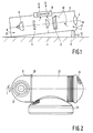
- FIG. 1 shows an embodiment of such apparatus.
- a rectangular housing 1 are provided from the rear end to the front end, and along a projection axis 14 a lamp 6, a filter 5, a converging lens 4, a liquid crystal display panel 3 and a projection lens 2.
- the housing 1 is provided with air inlet holes 7 and 8 for inhaling coolant ambient air and with a fan 9 for exhausting this air.
- the directions of the air streams are indicated by arrows 12.
- the projector housing is placed so as to have an inclination with respect to a surface 10 such as a table or the like by means of a stand 11 drawn by a dot line. Details of the stand 11 are not shown, but the upper end of the stand 11 is shifted in upward and downward direction, indicated by an arrow 13, by hand adjustment, which is a well-known technology.
- the purpose of the present invention is to solve these problems and to provide a compact projection apparatus of which the projection axis inclination angle can be set easily and accurately.
- This projection apparatus is characterized in that it comprises a first holder, for holding the projection lens and having a first optical axis, a second, tubular, holder for holding other components and having a second optical axis, the first optical axis being substantially perpendicular to the second optical axis, and a support for the second holder, and in that the first holder is rotatable around an axis parallel to the second optical axis.
- the light path is folded so that the length of the apparatus is decreased, and the projection axis inclination can be set easily by manually rotating the first holder.
- This apparatus may be further characterized in that the first holder comprises a reflector arranged at an angle of substantially 45° with the first optical axis and the second optical axis.
- a preferred embodiment of the apparatus according to the present invention is characterized in that the first holder is fixed to the second holder and in that the latter is rotatably arranged in a stationary case which is fixed to the support.
- the orientation of the liquid crystal display panel with respect to the projection lens is kept constant.
- a constructively preferred embodiment of the apparatus is characterized in that the second holder is provided with bearings supported in the stationary case and in that an elastic member is provided between an end portion of the second holder and the end of a neighbouring bearing.
- An embodiment of the projection apparatus wherein the liquid crystal display panel is arranged in a supporting member may be further characterized in that said member is provided on its surface with a plurality of radially arranged fins which surround the liquid crystal display panel.
- numeral 21 denotes the first holder which is arranged rotatably and comprises a projection lens 22.
- Numeral 23 denotes a tubular case which comprises other members of the optical projection system.
- the axis L of case 23 coincides with the rotation axis of holder 21.
- the case 23 may have a speaker part 24 at its end remote from the first holder 21.
- Numeral 25 denotes a support for the case 23.
- the support 25 may incorporate terminals of an electronic system, an electronic circuit, a fan, an adjustment member and the like.
- Numeral 26 denotes a coupling member which couples the first holder 21 rotatably to the case 23.
- This projection apparatus can be very compact.
- Figure 3 shows, in cross-section an embodiment of the projection apparatus in which the holder 21 of figure 2 forms a part 29b of an L-shaped holder 29, which has a second tubular holder part 29a.
- a lamp 30 In the latter a lamp 30, a filter 31, a converging lens 32 and a liquid crystal display panel 33 are accommodated.
- a reflector 34 In the holder 29b a reflector 34 is arranged which reflects the optical axis L of the beam emanating from the holder 29a over 90° so that it coincides with the axis of the projection lens 35.
- the tubular holder 29a is inserted between bearings 27 and 28 which are fitted in and fixed to the outer case 23 shown in figure 2.
- the holder 29 is fixed to the bearing 28 by means of a washer 36 and a ring shaped plate spring 37 between the rear end portion 29c of the holder and the rear side of bearing 28.
- the coupling part 26 comprises a similar spring construction which enables the holder 21 to be rotated by hand with respect to the outer case 23.
- the design of the apparatus may be such that only the holder 21 with the projection lens 35 and the reflector 34 is rotated to set the projection axis angle, it is preferred that the whole optical system, except the radiation source 30, is rotatable.
- the display panel 33 may also be accommodated in the holder 21.
- FIG 4 shows the cooling principle and figure 5 a perspective view of a heat radiating supporting member D for the display panel.
- A denotes a part containing the projection lens, the reflecting mirror and the like therein
- B denotes a fan provided in the support member 25
- C denotes another fan provided at the other end of the projector for example together with the speaker part 24
- D denotes a liquid-crystal-display-panel heat radiation supporting member arranged upwardly of the fan B.
- the supporting member carries the liquid crystal panel 33 therein and has a plurality of tapered fins d at its surface as clearly shown in Figure 5.
- Numeral 29 denotes a tube or the like and is integrally rotatable with A and D.
- E denotes an outer case containing the tubular holder 29a, the holder 21 and the like therein.
- a cooling operation according to the invention is as follows.
- the open air 40 is inhaled by the fan B and then reaches the liquid-crystal-display-panel supporting member D arranged upwardly, whereby the liquid crystal panel of which temperature is rising is cooled.
- the open air flows in a direction indicated by arrows so as to cool the other internal members, and finally is exhausted (43) by means of the fan C.
- the liquid-crystal-display-panel supporting member D is rotatable over any desired angle as described before, and a plurality of tapered fins d are arranged radially with respect to the liquid crystal device panel 33 such that the cool air reaches the liquid crystal panel 33 efficiently at any angle about which the liquid-crystal-panel-radiation member D rotates.
- a compact projector having a good operationability can be obtained.
- a complicated projection axis angle adjustment mechanism needed in the conventional projector can be omitted, whereby a considerable cost reduction can be obtained.
- the projector Since the projector is compact, it can easily be carried to any place. Especially, if the compact projector is used in a car or in a plane in which space is very limited, projection can easily be performed by using a ceiling, wall or the like as a screen since the projection lens holding part is rotatable.
- cooling of the liquid crystal device panel can be performed efficiently only by providing a plurality of fins arranged radially on the panel supporting member in compliance with the rotation construction according to the invention, without having a complicated construction like before.
Abstract
Description
- The present invention relates to an optical projection apparatus comprising, in this order, a light source, a liquid crystal display panel and a projection lens for projecting an image generated by said panel onto a projection screen.
- Such apparatus is widely known, and figure 1 shows an embodiment of such apparatus. In a
rectangular housing 1 are provided from the rear end to the front end, and along a projection axis 14 a lamp 6, a filter 5, a converging lens 4, a liquid crystal display panel 3 and aprojection lens 2. Thehousing 1 is provided with air inlet holes 7 and 8 for inhaling coolant ambient air and with afan 9 for exhausting this air. The directions of the air streams are indicated byarrows 12. - The projector housing is placed so as to have an inclination with respect to a
surface 10 such as a table or the like by means of astand 11 drawn by a dot line. Details of thestand 11 are not shown, but the upper end of thestand 11 is shifted in upward and downward direction, indicated by anarrow 13, by hand adjustment, which is a well-known technology. - It is difficult to make the conventional projector compact due to its construction. Furthermore a complicated angle adjustment mechanism for adjusting the inclination of the body is required in order to project an image onto a screen.
- The purpose of the present invention is to solve these problems and to provide a compact projection apparatus of which the projection axis inclination angle can be set easily and accurately. This projection apparatus is characterized in that it comprises a first holder, for holding the projection lens and having a first optical axis, a second, tubular, holder for holding other components and having a second optical axis, the first optical axis being substantially perpendicular to the second optical axis, and a support for the second holder, and in that the first holder is rotatable around an axis parallel to the second optical axis.
- In this projection apparatus the light path is folded so that the length of the apparatus is decreased, and the projection axis inclination can be set easily by manually rotating the first holder.
- This apparatus may be further characterized in that the first holder comprises a reflector arranged at an angle of substantially 45° with the first optical axis and the second optical axis.
- By the 45° reflector folding of the light path is achieved in the most simple way.
- A preferred embodiment of the apparatus according to the present invention is characterized in that the first holder is fixed to the second holder and in that the latter is rotatably arranged in a stationary case which is fixed to the support.
- As the second holder rotates with the first holder, the orientation of the liquid crystal display panel with respect to the projection lens is kept constant.
- A constructively preferred embodiment of the apparatus is characterized in that the second holder is provided with bearings supported in the stationary case and in that an elastic member is provided between an end portion of the second holder and the end of a neighbouring bearing.
- An embodiment of the projection apparatus wherein the liquid crystal display panel is arranged in a supporting member, may be further characterized in that said member is provided on its surface with a plurality of radially arranged fins which surround the liquid crystal display panel.
- The invention will now be described more in detail by referring to the accompanying drawings, in which
- Figure 1 shows a conventional projection apparatus,
- Figure 2 shows a view of the apparatus according to the invention,
- Figure 3 shows an embodiment of this apparatus in cross-section,
- Figure 4 illustrates how cooling is performed in this apparatus, and
- Figure 5 shows a liquid crystal panel supporting member for use in this apparatus.
- In figure 1
numeral 21 denotes the first holder which is arranged rotatably and comprises aprojection lens 22. Numeral 23 denotes a tubular case which comprises other members of the optical projection system. The axis L ofcase 23 coincides with the rotation axis ofholder 21. Thecase 23 may have aspeaker part 24 at its end remote from thefirst holder 21. Numeral 25 denotes a support for thecase 23. Thesupport 25 may incorporate terminals of an electronic system, an electronic circuit, a fan, an adjustment member and the like. Numeral 26 denotes a coupling member which couples thefirst holder 21 rotatably to thecase 23. This projection apparatus can be very compact. - Figure 3 shows, in cross-section an embodiment of the projection apparatus in which the
holder 21 of figure 2 forms apart 29b of an L-shaped holder 29, which has a secondtubular holder part 29a. In the latter alamp 30, afilter 31, a converginglens 32 and a liquidcrystal display panel 33 are accommodated. In theholder 29b areflector 34 is arranged which reflects the optical axis L of the beam emanating from theholder 29a over 90° so that it coincides with the axis of theprojection lens 35. - The
tubular holder 29a is inserted betweenbearings outer case 23 shown in figure 2. Theholder 29 is fixed to thebearing 28 by means of awasher 36 and a ring shapedplate spring 37 between therear end portion 29c of the holder and the rear side ofbearing 28. Thecoupling part 26 comprises a similar spring construction which enables theholder 21 to be rotated by hand with respect to theouter case 23. - Although the design of the apparatus may be such that only the
holder 21 with theprojection lens 35 and thereflector 34 is rotated to set the projection axis angle, it is preferred that the whole optical system, except theradiation source 30, is rotatable. Thedisplay panel 33 may also be accommodated in theholder 21. - In order to ensure that in the case of a rotatable display panel this panel is efficiently cooled at any angle position of the panel, according to the invention special cooling means are provided as illustrated in figures 4 and 5. Figure 4 shows the cooling principle and figure 5 a perspective view of a heat radiating supporting member D for the display panel. In these figures A denotes a part containing the projection lens, the reflecting mirror and the like therein, B denotes a fan provided in the
support member 25, C denotes another fan provided at the other end of the projector for example together with thespeaker part 24 and D denotes a liquid-crystal-display-panel heat radiation supporting member arranged upwardly of the fan B. The supporting member carries theliquid crystal panel 33 therein and has a plurality of tapered fins d at its surface as clearly shown in Figure 5. - Numeral 29 denotes a tube or the like and is integrally rotatable with A and D. E denotes an outer case containing the
tubular holder 29a, theholder 21 and the like therein. - With the above-described construction, a cooling operation according to the invention is as follows. The
open air 40 is inhaled by the fan B and then reaches the liquid-crystal-display-panel supporting member D arranged upwardly, whereby the liquid crystal panel of which temperature is rising is cooled. Then the open air flows in a direction indicated by arrows so as to cool the other internal members, and finally is exhausted (43) by means of the fan C. The liquid-crystal-display-panel supporting member D is rotatable over any desired angle as described before, and a plurality of tapered fins d are arranged radially with respect to the liquidcrystal device panel 33 such that the cool air reaches theliquid crystal panel 33 efficiently at any angle about which the liquid-crystal-panel-radiation member D rotates. - An explanation on the operation of the liquid crystal display projector is omitted since it is well-known.
- The above-described embodiments are only examples and various embodiments can be adopted within the scope of the invention without deviating from the invention.
- According to the invention as described above, a compact projector having a good operationability can be obtained. In such a projector, a complicated projection axis angle adjustment mechanism needed in the conventional projector can be omitted, whereby a considerable cost reduction can be obtained.
- Since the projector is compact, it can easily be carried to any place. Especially, if the compact projector is used in a car or in a plane in which space is very limited, projection can easily be performed by using a ceiling, wall or the like as a screen since the projection lens holding part is rotatable.
- Furthermore, according to the invention, cooling of the liquid crystal device panel can be performed efficiently only by providing a plurality of fins arranged radially on the panel supporting member in compliance with the rotation construction according to the invention, without having a complicated construction like before.
Claims (6)
- An optical projection apparatus comprising in this order, a light source, a liquid crystal display panel and a projection lens for projecting an image generated by said panel onto a projection screen, characterized in that it comprises a first holder, for holding the projection lens and having a first optical axis, a second, tubular, holder for holding other components and having a second optical axis, the first optical axis being substantially perpendicular to the second optical axis, and a support for the second holder, and in that the first holder is rotatable around an axis parallel to the second optical axis.
- An optical projection apparatus as claimed in Claim 1, characterized in that the first holder comprises a reflector arranged at an angle of substantially 45° with the first optical axis and the second optical axis.
- An optical projection apparatus as claimed in Claim 1 or 2, characterized in that the first holder is fixed to the second holder and in that the latter is rotatably arranged in a stationary case which is fixed to the support.
- An optical projection apparatus as claimed in Claim 3, characterized in that the second holder is provided with bearings supported in the stationary case and in that an elastic member is provided between an end portion of the second holder and the end of a neighbouring bearing.
- An optical projection apparatus as claimed in Claim 1, 2, 3 or 4, characterized in that the liquid crystal display panel is rotatable with the first holder.
- An optical projection apparatus as claimed in Claim 5, having a supporting member for the liquid crystal display panel, characterized in that said member is provided on its surface with a plurality of radially arranged fins which surround the panel.
Applications Claiming Priority (4)
| Application Number | Priority Date | Filing Date | Title |
|---|---|---|---|
| JP8854292U JPH0647922U (en) | 1992-12-02 | 1992-12-02 | LCD projector |
| JP345112/92 | 1992-12-02 | ||
| JP88542/92 | 1992-12-02 | ||
| JP34511292A JPH06175099A (en) | 1992-12-02 | 1992-12-02 | Liquid crystal projector |
Publications (2)
| Publication Number | Publication Date |
|---|---|
| EP0601628A1 true EP0601628A1 (en) | 1994-06-15 |
| EP0601628B1 EP0601628B1 (en) | 1998-03-18 |
Family
ID=26429911
Family Applications (1)
| Application Number | Title | Priority Date | Filing Date |
|---|---|---|---|
| EP93203319A Expired - Lifetime EP0601628B1 (en) | 1992-12-02 | 1993-11-26 | Optical projection apparatus |
Country Status (5)
| Country | Link |
|---|---|
| US (1) | US5459539A (en) |
| EP (1) | EP0601628B1 (en) |
| KR (1) | KR100369087B1 (en) |
| DE (1) | DE69317520T2 (en) |
| TW (1) | TW249847B (en) |
Cited By (4)
| Publication number | Priority date | Publication date | Assignee | Title |
|---|---|---|---|---|
| US5606436A (en) * | 1994-11-21 | 1997-02-25 | Proxima Corporation | Liquid crystal projection panel construction and method of making same |
| GB2306266A (en) * | 1995-10-13 | 1997-04-30 | Grunwald Projektoren Ag | LCD projector with uniform cooling of the LCD |
| EP0847206A1 (en) * | 1996-11-29 | 1998-06-10 | Gi-Zeta di Giuseppe Zacché | Method for projecting and moving images |
| WO2005060269A1 (en) * | 2003-12-16 | 2005-06-30 | Koninklijke Philips Electronics, N.V. | Rotatable projection lens for rear-projection applications |
Families Citing this family (32)
| Publication number | Priority date | Publication date | Assignee | Title |
|---|---|---|---|---|
| EP0675476B1 (en) * | 1994-03-30 | 1998-06-03 | Denso Corporation | Liquid crystal display device |
| KR0140672B1 (en) * | 1994-09-15 | 1998-06-15 | 이헌조 | L.c.d projector with deflection apparatus |
| US5820242A (en) * | 1996-03-29 | 1998-10-13 | Minnesota Mining And Manufacturing Company | Compact integrated LCD projector |
| JP3371190B2 (en) * | 1996-05-24 | 2003-01-27 | ソニー株式会社 | Projection type liquid crystal display |
| US6046858A (en) * | 1997-10-16 | 2000-04-04 | Aurora Systems, Inc. | Light separation and recombination system for an off-axis projector |
| US6375330B1 (en) | 1999-12-30 | 2002-04-23 | Gain Micro-Optics, Inc. | Reflective liquid-crystal-on-silicon projection engine architecture |
| US20020176054A1 (en) * | 1999-12-30 | 2002-11-28 | Mihalakis George M. | Reflective liquid-crystal-on-silicon projection engine architecture |
| US6508085B1 (en) | 2000-08-23 | 2003-01-21 | American Trim, Llc | Horizontal axis washer or dryer door with viewing system |
| US7182472B2 (en) * | 2001-10-22 | 2007-02-27 | Emerald Innovations, L.L.C. | Image projection apparatus |
| US6695452B2 (en) * | 2000-10-27 | 2004-02-24 | Emerald Innovations, Llc | Image projection apparatus |
| US6505940B1 (en) * | 2000-10-31 | 2003-01-14 | Eastman Kodak Company | Digital projector |
| GB2382881A (en) * | 2001-12-10 | 2003-06-11 | Wynne Willson Gottelier Ltd | Digital image projector with deflector array |
| US7018053B2 (en) * | 2003-10-23 | 2006-03-28 | Hewlett-Packard Development Company, L.P. | Projector |
| US7271964B2 (en) * | 2003-12-05 | 2007-09-18 | 3M Innovative Properties Company | Projection display device for multimedia and wall display systems |
| TW200528757A (en) * | 2003-12-05 | 2005-09-01 | 3M Innovative Properties Co | Wide-angle projection lens and optical engine for a projection display device |
| DE102004031700B4 (en) * | 2004-06-30 | 2010-02-18 | Airbus Deutschland Gmbh | Airplane with information display system |
| US7320521B2 (en) * | 2004-07-12 | 2008-01-22 | Next Wave Optics, Inc. | Optical engine architectures |
| US7530693B2 (en) * | 2005-05-31 | 2009-05-12 | Next Wave Optics Inc. | Single MEMS imager optical engine |
| CN101140411B (en) * | 2006-09-05 | 2010-09-29 | 深圳华强三洋技术设计有限公司 | Projection device |
| US9752761B2 (en) | 2014-07-16 | 2017-09-05 | Telebrands Corp. | Landscape light |
| USD773707S1 (en) | 2014-10-30 | 2016-12-06 | Telebrands Corp. | Landscape light |
| USD766483S1 (en) | 2015-05-11 | 2016-09-13 | Telebrands Corp. | Light projector |
| USD766484S1 (en) | 2015-05-11 | 2016-09-13 | Telebrands Corp. | Light projector |
| USD816890S1 (en) | 2015-05-11 | 2018-05-01 | Telebrands Corp. | Light projector |
| USD824066S1 (en) | 2015-05-11 | 2018-07-24 | Telebrands Corp. | Light projector |
| USD778478S1 (en) | 2015-05-11 | 2017-02-07 | Telebrands Corp. | Light projector |
| US9546775B1 (en) | 2015-12-03 | 2017-01-17 | Telebrands Corp. | Decorative lighting apparatus having two laser light sources |
| US9879847B2 (en) | 2015-12-03 | 2018-01-30 | Telebrands Corp. | Decorative lighting apparatus having two laser light sources |
| US9458994B1 (en) | 2015-12-03 | 2016-10-04 | Telebrands Corp. | Decorative lighting apparatus having two laser light sources and a switch |
| US9562673B1 (en) | 2015-12-03 | 2017-02-07 | Telebrands Corp. | Decorative lighting apparatus having an attenuation assembly |
| USD797975S1 (en) | 2016-09-29 | 2017-09-19 | Telebrands Corp. | Landscape light |
| USD798484S1 (en) | 2016-09-29 | 2017-09-26 | Telebrands Corp. | Landscape light |
Citations (4)
| Publication number | Priority date | Publication date | Assignee | Title |
|---|---|---|---|---|
| FR2279127A1 (en) * | 1974-07-18 | 1976-02-13 | Grivelet Etienne | Projector appts. for simultaneous images on different surfaces - has projectors in housings rotatably stacked on common axis |
| US4735499A (en) * | 1983-11-28 | 1988-04-05 | Fuji Photo Film Co., Ltd. | Film carrier support mechanism for film projector |
| EP0421628A2 (en) * | 1989-10-05 | 1991-04-10 | Seiko Epson Corporation | Projection type liquid crystal display device |
| EP0492721A2 (en) * | 1990-12-27 | 1992-07-01 | Koninklijke Philips Electronics N.V. | Color display device and circuitry for addressing the light valve of said device |
Family Cites Families (3)
| Publication number | Priority date | Publication date | Assignee | Title |
|---|---|---|---|---|
| EP0192023A3 (en) * | 1985-02-21 | 1986-10-08 | Casio Computer Company Limited | Liquid crystal projector |
| US5037196A (en) * | 1987-10-21 | 1991-08-06 | Sharp Kabushiki Kaisha | Projection-type color display apparatus |
| JPH04306629A (en) * | 1991-04-04 | 1992-10-29 | Matsushita Electric Ind Co Ltd | Projector |
-
1993
- 1993-11-26 DE DE69317520T patent/DE69317520T2/en not_active Expired - Fee Related
- 1993-11-26 EP EP93203319A patent/EP0601628B1/en not_active Expired - Lifetime
- 1993-12-02 KR KR1019930026200A patent/KR100369087B1/en not_active IP Right Cessation
- 1993-12-02 US US08/161,957 patent/US5459539A/en not_active Expired - Fee Related
- 1993-12-15 TW TW082110637A patent/TW249847B/zh active
Patent Citations (4)
| Publication number | Priority date | Publication date | Assignee | Title |
|---|---|---|---|---|
| FR2279127A1 (en) * | 1974-07-18 | 1976-02-13 | Grivelet Etienne | Projector appts. for simultaneous images on different surfaces - has projectors in housings rotatably stacked on common axis |
| US4735499A (en) * | 1983-11-28 | 1988-04-05 | Fuji Photo Film Co., Ltd. | Film carrier support mechanism for film projector |
| EP0421628A2 (en) * | 1989-10-05 | 1991-04-10 | Seiko Epson Corporation | Projection type liquid crystal display device |
| EP0492721A2 (en) * | 1990-12-27 | 1992-07-01 | Koninklijke Philips Electronics N.V. | Color display device and circuitry for addressing the light valve of said device |
Cited By (4)
| Publication number | Priority date | Publication date | Assignee | Title |
|---|---|---|---|---|
| US5606436A (en) * | 1994-11-21 | 1997-02-25 | Proxima Corporation | Liquid crystal projection panel construction and method of making same |
| GB2306266A (en) * | 1995-10-13 | 1997-04-30 | Grunwald Projektoren Ag | LCD projector with uniform cooling of the LCD |
| EP0847206A1 (en) * | 1996-11-29 | 1998-06-10 | Gi-Zeta di Giuseppe Zacché | Method for projecting and moving images |
| WO2005060269A1 (en) * | 2003-12-16 | 2005-06-30 | Koninklijke Philips Electronics, N.V. | Rotatable projection lens for rear-projection applications |
Also Published As
| Publication number | Publication date |
|---|---|
| DE69317520T2 (en) | 1998-09-24 |
| US5459539A (en) | 1995-10-17 |
| KR100369087B1 (en) | 2003-12-11 |
| KR940015572A (en) | 1994-07-21 |
| TW249847B (en) | 1995-06-21 |
| DE69317520D1 (en) | 1998-04-23 |
| EP0601628B1 (en) | 1998-03-18 |
Similar Documents
| Publication | Publication Date | Title |
|---|---|---|
| US5459539A (en) | Optical projection apparatus | |
| US5343262A (en) | Portable LCD projector | |
| US9423676B2 (en) | Lighting unit and image projector | |
| EP0192023A2 (en) | Liquid crystal projector | |
| US5208891A (en) | Fiber-optic viewgraph projector | |
| JP2006511839A (en) | Compact integrated reflective projection system | |
| US5664859A (en) | Projection display docking system | |
| JP2004085752A (en) | Image projector | |
| EP2824922B1 (en) | Projector comprising a cooling system | |
| US3711194A (en) | Overhead projection apparatus | |
| JPH07295097A (en) | Heat radiation mechanism of apparatus | |
| US20030202224A1 (en) | Image pick-up device | |
| US2501469A (en) | Photographic enlarger and camera | |
| JP2935214B2 (en) | liquid crystal television | |
| JP5051416B2 (en) | Moving lens mechanism with movable diaphragm and projector equipped with this lens mechanism | |
| JPH02267535A (en) | Liquid crystal display device | |
| JPH0749533A (en) | Projector device | |
| JP2540833B2 (en) | Display device | |
| JPS6232431A (en) | Projecting device | |
| JPH0667143A (en) | Liquid crystal type projector | |
| JPH06175099A (en) | Liquid crystal projector | |
| JP3324293B2 (en) | LCD projector | |
| US3314330A (en) | Overhead projector | |
| JP3467032B2 (en) | projector | |
| JPS6333218Y2 (en) |
Legal Events
| Date | Code | Title | Description |
|---|---|---|---|
| PUAI | Public reference made under article 153(3) epc to a published international application that has entered the european phase |
Free format text: ORIGINAL CODE: 0009012 |
|
| AK | Designated contracting states |
Kind code of ref document: A1 Designated state(s): DE FR GB IT |
|
| RAP1 | Party data changed (applicant data changed or rights of an application transferred) |
Owner name: N.V. PHILIPS' GLOEILAMPENFABRIEKEN |
|
| 17P | Request for examination filed |
Effective date: 19941215 |
|
| 17Q | First examination report despatched |
Effective date: 19951218 |
|
| GRAG | Despatch of communication of intention to grant |
Free format text: ORIGINAL CODE: EPIDOS AGRA |
|
| GRAH | Despatch of communication of intention to grant a patent |
Free format text: ORIGINAL CODE: EPIDOS IGRA |
|
| GRAH | Despatch of communication of intention to grant a patent |
Free format text: ORIGINAL CODE: EPIDOS IGRA |
|
| GRAA | (expected) grant |
Free format text: ORIGINAL CODE: 0009210 |
|
| AK | Designated contracting states |
Kind code of ref document: B1 Designated state(s): DE FR GB IT |
|
| REF | Corresponds to: |
Ref document number: 69317520 Country of ref document: DE Date of ref document: 19980423 |
|
| ITF | It: translation for a ep patent filed |
Owner name: ING. C. GREGORJ S.P.A. |
|
| ET | Fr: translation filed | ||
| RAP4 | Party data changed (patent owner data changed or rights of a patent transferred) |
Owner name: KONINKLIJKE PHILIPS ELECTRONICS N.V. |
|
| REG | Reference to a national code |
Ref country code: FR Ref legal event code: CD |
|
| PLBE | No opposition filed within time limit |
Free format text: ORIGINAL CODE: 0009261 |
|
| STAA | Information on the status of an ep patent application or granted ep patent |
Free format text: STATUS: NO OPPOSITION FILED WITHIN TIME LIMIT |
|
| 26N | No opposition filed | ||
| REG | Reference to a national code |
Ref country code: GB Ref legal event code: IF02 |
|
| REG | Reference to a national code |
Ref country code: GB Ref legal event code: 746 Effective date: 20020917 |
|
| REG | Reference to a national code |
Ref country code: FR Ref legal event code: D6 |
|
| PGFP | Annual fee paid to national office [announced via postgrant information from national office to epo] |
Ref country code: DE Payment date: 20050118 Year of fee payment: 12 |
|
| PGFP | Annual fee paid to national office [announced via postgrant information from national office to epo] |
Ref country code: GB Payment date: 20051129 Year of fee payment: 13 Ref country code: FR Payment date: 20051129 Year of fee payment: 13 |
|
| PG25 | Lapsed in a contracting state [announced via postgrant information from national office to epo] |
Ref country code: DE Free format text: LAPSE BECAUSE OF NON-PAYMENT OF DUE FEES Effective date: 20060601 |
|
| PGFP | Annual fee paid to national office [announced via postgrant information from national office to epo] |
Ref country code: IT Payment date: 20061130 Year of fee payment: 14 |
|
| GBPC | Gb: european patent ceased through non-payment of renewal fee |
Effective date: 20061126 |
|
| REG | Reference to a national code |
Ref country code: FR Ref legal event code: ST Effective date: 20070731 |
|
| PG25 | Lapsed in a contracting state [announced via postgrant information from national office to epo] |
Ref country code: GB Free format text: LAPSE BECAUSE OF NON-PAYMENT OF DUE FEES Effective date: 20061126 |
|
| PG25 | Lapsed in a contracting state [announced via postgrant information from national office to epo] |
Ref country code: FR Free format text: LAPSE BECAUSE OF NON-PAYMENT OF DUE FEES Effective date: 20061130 |
|
| PG25 | Lapsed in a contracting state [announced via postgrant information from national office to epo] |
Ref country code: IT Free format text: LAPSE BECAUSE OF NON-PAYMENT OF DUE FEES Effective date: 20071126 |