EP0601338A1 - Electrode system for a defibrillator - Google Patents
Electrode system for a defibrillator Download PDFInfo
- Publication number
- EP0601338A1 EP0601338A1 EP93118002A EP93118002A EP0601338A1 EP 0601338 A1 EP0601338 A1 EP 0601338A1 EP 93118002 A EP93118002 A EP 93118002A EP 93118002 A EP93118002 A EP 93118002A EP 0601338 A1 EP0601338 A1 EP 0601338A1
- Authority
- EP
- European Patent Office
- Prior art keywords
- electrode
- electrodes
- heart
- vena cava
- electrode system
- Prior art date
- Legal status (The legal status is an assumption and is not a legal conclusion. Google has not performed a legal analysis and makes no representation as to the accuracy of the status listed.)
- Granted
Links
Images

Classifications
-
- A—HUMAN NECESSITIES
- A61—MEDICAL OR VETERINARY SCIENCE; HYGIENE
- A61N—ELECTROTHERAPY; MAGNETOTHERAPY; RADIATION THERAPY; ULTRASOUND THERAPY
- A61N1/00—Electrotherapy; Circuits therefor
- A61N1/02—Details
- A61N1/04—Electrodes
- A61N1/05—Electrodes for implantation or insertion into the body, e.g. heart electrode
- A61N1/056—Transvascular endocardial electrode systems
- A61N1/0563—Transvascular endocardial electrode systems specially adapted for defibrillation or cardioversion
-
- A—HUMAN NECESSITIES
- A61—MEDICAL OR VETERINARY SCIENCE; HYGIENE
- A61N—ELECTROTHERAPY; MAGNETOTHERAPY; RADIATION THERAPY; ULTRASOUND THERAPY
- A61N1/00—Electrotherapy; Circuits therefor
- A61N1/18—Applying electric currents by contact electrodes
- A61N1/32—Applying electric currents by contact electrodes alternating or intermittent currents
- A61N1/38—Applying electric currents by contact electrodes alternating or intermittent currents for producing shock effects
- A61N1/39—Heart defibrillators
- A61N1/3918—Heart defibrillators characterised by shock pathway, e.g. by electrode configuration
-
- A—HUMAN NECESSITIES
- A61—MEDICAL OR VETERINARY SCIENCE; HYGIENE
- A61N—ELECTROTHERAPY; MAGNETOTHERAPY; RADIATION THERAPY; ULTRASOUND THERAPY
- A61N1/00—Electrotherapy; Circuits therefor
- A61N1/02—Details
- A61N1/04—Electrodes
- A61N1/05—Electrodes for implantation or insertion into the body, e.g. heart electrode
- A61N1/056—Transvascular endocardial electrode systems
- A61N2001/0585—Coronary sinus electrodes
Definitions
- This invention relates generally to an electrode system intended for proximal connection to a cardioverter/defibrillator and for distal placement in the heart region to deliver electrical energy from the cardioverter/defibrillator to the heart so an arrhythmia in the heart can be terminated. More specifically, the invention relates to a system with three electrodes, at least two of which intravascular as stated in the preambula of claim 1.
- defibrillation/cardioversion in this context refers to defibrillation using lower energy; the collective designation “defibrillation” will henceforth be used below
- defibrillation/cardioversion using a three-electrode system with two intravascular electrodes, one of the intravascular electrodes is normally placed in the right ventricle and the other either in the superior vena cava or, less commonly, in the inferior vena cava or even in the coronary sinus and its prolongation along the base of the heart.
- the third electrode is arranged as a subcutaneous electrode with a large area, i.e.
- a patch electrode for the purpose of achieving efficient utilization of the energy stored in the heart and good distribution of current in the heart while simultaneously avoiding major surgery (opening of the thorax).
- the subcutaneous patch electrode is usually placed in the vicinity of the left ventricle between the patient's thorax and skin.
- Electrode systems with the above-described locations are shown among a plurality of others in US-A-4 708 145.
- intravascular electrodes shown there with a common electrode cable for a plurality of electrodes in the right ventricle and superior vena cava, separate electrode cables for different electrodes, as well as a separate sensing electrode for detecting cardiac events, are also possible. This is shown in US-A-4 727 877, EP-A-0 373 953 and US-A-5 044 375 respectively.
- a common feature of placements in the prior art systems is an electrode in the right electrode.
- an endocardiac electrode shown in the applicant's previous application, EP 92 104 098, applicant reference GR 92 P 7303, imposes strain on the heart in the form of irritation of the musculature of the heart wall and the valves between the atrium and ventricle.
- the previously cited application proposed an electrode placement in which the endocardiac electrode is avoided and replaced by an electrode in the inferior vena cava.
- the purpose of the invention is to achieve an electrode system, without the ventricular electrode, in which efficient utilization of the energy stored in the defibrillator is combined with favorable distribution of current in the heart.
- a three-electrode system is therefore attained, without a ventricular electrode, for defibrillation with at least two intravascular electrodes, one of which placeable in the coronary sinus including its prolongation along the base of the heart.
- the venous electrodes can be arranged along a common electrode cable and/or have means for fixation to the inner venous wall.
- the fixation means can be in the form of a hollow, resilient cylinder, fixation being achieved through the cylinder's radial expansion.
- the hollow cylindrical shape of the electrode enables blood to flow unimpeded through the electrode.
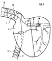
- FIG. 1 and 2 Identical reference designations designate the same or similar parts in the FIGURES.
- hidden electrode parts in the inferior vena cava and the vein itself are dashed.
- FIG. 1 shows a cross-section of a heart and a number of vessels of relevance to the invention.
- a first electrode cable 10 is introduced through the superior vena cava 2, passes through the right atrium 4 and exits into the inferior vena cava 6. At its distal end, the cable 10 bears an electrode 12 anchored in the inferior vena cava (6).
- the cable also has an additional electrode 14 anchored in the superior vena cava 2 proximal to the electrode 12.
- a second electrode cable 16 is also introduced through the superior vena cava 2 but passes through the right atrium 4, in contrast to the cable 10, in such a way that it exits into the coronary sinus 8 and its prolongation, the great cardiac vein, along the base of the heart.
- the cable 16 bears an electrode 18 anchored in the coronary sinus/great cardiac vein 8.
- the electrode 18 is connectable to the defibrillator by a conductor present in the cable 16.
- the electrodes 12 and 14 are also individually connectable to the defibrillator by separate conductors present in the cable 10.
- the electrode system according to FIG. 2 differs from the system shown in FIG. 1 by replacement of the electrode 14 sited in the superior vena cava 2 with a subcutaneous patch electrode 17 near the left ventricle 7, the patch electrode connectable to the defibrillator by an existing conductor in the cable 19.
- subcutaneous placement means placement between the thorax (including the ribs) and skin.
- the defibrillator's enclosure can alternately be used as a patch electrode.
- connection of the electrodes to the defibrillator according to FIG. 1 and FIG. 2 and between one another can be achieved in different ways.
- the electrodes 14, 18 in FIG. 1 can be interconnected so the defibrillation impulse is emitted between these electrodes, on the one hand, and the electrode 12 in the inferior vena cava 6, on the other hand.
- the electrodes 17, 18 in FIG. 2 can be interconnected so the defibrillation pulse is emitted between these electrodes, on the one hand, and the electrode 12, on the other hand.
- the electrodes 12, 14, 18 and 12, 17, 18 respectively can be interconnected in such a way that the defibrillation pulse is emitted between another one of these electrodes, on the one hand, and the other two electrodes, on the other hand.
- the electrodes 12, 14, 18 and 12, 17, 18 respectively can be supplied with different defibrillation voltages or, as an additional alternative, pairs can deliver defibrillation pulses sequentially. Mono-, bi- or multiphasic defibrillation pulses can be used.
- the cable 10 shown in FIG. 1 common to the two electrodes 12, 14 can be replaced with separate electrode cables for these two electrodes 12, 14.
- Introduction through the inferior vena cava 6 can be an alternative for the described introduction of intravascular electrodes through the superior vena cava 2.
- the intravascular electrodes can have a common electrode cable or separate electrode cables also in the latter introduction route.
- the electrodes 12, 18 can alternately have a common electrode cable in the configurations shown in both FIG. 1 and FIG. 2.
- the described electrode configurations can also be complemented with a separate stimulation/sensing electrode for stimulating/sensing cardiac events and/or a sensor for different parameters related to e.g. cardiac hemodynamics.
- the sensing electrode cable can also contain a stimulation electrode for pacing functions.
- the intravascular electrodes 12, 14, 18 are kept in place in the respective vein by being constructed in a way making them radially expandable, then forming at least the contours of a hollow cylinder in the expanded state. Defibrillation electrodes of this type are described in detail in the applicant's simultaneously filed patent application entitled "Defibrillation electrode", applicant reference GR 92 P 7364, this reference forming a part of the present application so as to avoid repetition.
- the intravascular electrodes 12, 14, 18 are therefore e.g. kept in place in the respective vein by being shaped in the form of helices which apply pressure to the inner wall of the vein by being biased perpendicular to the longitudinal axis of the helix.
- the helical electrode 12 can be envisaged as being coiled around an imaginary cylinder whose external diameter is somewhat larger than the caliber of the inferior vena cava 6.
- the helix can be made of an electrically conductive, biocompatible material.
- the electrode 12 is connected to the electrode cable 10 in such a way that they jointly form a single unit.
- a centrally arranged longitudinal channel through which a stylet can be introduced runs through the electrode 12 and electrode cable 10.
- the electrode 12 In implantation, the electrode 12 is straightened out with the aid of the stylet, the diameter of the electrode 12 thereby becoming smaller than the diameter of the blood vessels it is to traverse and enabling it to be advanced into the inferior vena cava 6.
- the stylet can be withdrawn, causing the electrode 12 to resume its preshaped helical configuration.
- the pressure of the helix against the venous wall keeps the helix in the desired position.
- the electrode 12 forms a relatively large electrode surface pressing on the vascular wall.
- the helical electrode 12 has the advantage of enabling blood in the vessel to flow unobstructed through the interior of the helix.
- the electrode 12 can also be readily repositioned by reintroduction of the stylet into the central channel to straighten out the electrode 12. The implanting physician can therefore easily find a site for the electrode 12 which, with the other electrodes, achieves a favorable distribution of current in heart tissue.
- the physician can employ an introductory catheter instead of a stylet.
- the electrode cable 10 with the straightened electrode 12 is inserted into the introductory catheter, the latter being sufficiently stiff to keep the electrode 12 straightened out during implantation.
- the introductory catheter can be withdrawn so the electrode resumes its preformed configuration.
- the implantation can be performed with the aid of a single stylet in a central channel running along the length of the electrodes 12, 14 and the catheter 10. Both electrodes 12 and 14 are then straightened out for implantation.
- the stylet is withdrawn enough for the electrode 12 to resume its helical configuration.
- the electrode 14 is then positioned at the desired site in the superior vena cava 2.
- the stylet is completely withdrawn so the electrode 14 also resumes its original, preshaped configuration.
- An introductory catheter can also be used instead of the stylet.
- the electrode 18 intended for location in the coronary sinus 8 and its prolongation along the base of the heart can consist of e.g. two sub-electrodes placed in the coronary sinus 8 and its prolongation respectively.
- the two sub-electrodes can be arranged on a common prolongation of e.g. the electrode cable 16.
- the two sub-electrodes are placed in the coronary sinus 8 and its prolongation in such a way that an individually adapted, additionally improved distribution of current in the heart is achieved.
- implantation is performed in the same way as described above. More than two sub-electrodes can be used.
Abstract
Description
- This invention relates generally to an electrode system intended for proximal connection to a cardioverter/defibrillator and for distal placement in the heart region to deliver electrical energy from the cardioverter/defibrillator to the heart so an arrhythmia in the heart can be terminated. More specifically, the invention relates to a system with three electrodes, at least two of which intravascular as stated in the preambula of
claim 1. - In defibrillation/cardioversion ("cardioversion" in this context refers to defibrillation using lower energy; the collective designation "defibrillation" will henceforth be used below) using a three-electrode system with two intravascular electrodes, one of the intravascular electrodes is normally placed in the right ventricle and the other either in the superior vena cava or, less commonly, in the inferior vena cava or even in the coronary sinus and its prolongation along the base of the heart. The third electrode is arranged as a subcutaneous electrode with a large area, i.e. a patch electrode, for the purpose of achieving efficient utilization of the energy stored in the heart and good distribution of current in the heart while simultaneously avoiding major surgery (opening of the thorax). The subcutaneous patch electrode is usually placed in the vicinity of the left ventricle between the patient's thorax and skin.
- Electrode systems with the above-described locations are shown among a plurality of others in US-A-4 708 145. In addition to the intravascular electrodes shown there with a common electrode cable for a plurality of electrodes in the right ventricle and superior vena cava, separate electrode cables for different electrodes, as well as a separate sensing electrode for detecting cardiac events, are also possible. This is shown in US-A-4 727 877, EP-A-0 373 953 and US-A-5 044 375 respectively.
- A common feature of placements in the prior art systems is an electrode in the right electrode. However, such an endocardiac electrode, shown in the applicant's previous application, EP 92 104 098, applicant reference GR 92 P 7303, imposes strain on the heart in the form of irritation of the musculature of the heart wall and the valves between the atrium and ventricle. There is a concomitant increased risk of blood clot formation. So the previously cited application proposed an electrode placement in which the endocardiac electrode is avoided and replaced by an electrode in the inferior vena cava.
- The purpose of the invention is to achieve an electrode system, without the ventricular electrode, in which efficient utilization of the energy stored in the defibrillator is combined with favorable distribution of current in the heart.
- This purpose is achieved with an electrode system of the above-described type with the features specified in
patent claim 1. - With a design according to the invention, a three-electrode system is therefore attained, without a ventricular electrode, for defibrillation with at least two intravascular electrodes, one of which placeable in the coronary sinus including its prolongation along the base of the heart.
- In the advantageous embodiments according to the invention described in the sub-claims, at least some of the venous electrodes can be arranged along a common electrode cable and/or have means for fixation to the inner venous wall. The fixation means can be in the form of a hollow, resilient cylinder, fixation being achieved through the cylinder's radial expansion. The hollow cylindrical shape of the electrode enables blood to flow unimpeded through the electrode. Other advantageous embodiments are also described in the sub-claims.
- The electrode system according to the invention will be described below, referring to an attached drawing in which
- FIG. 1 schematically shows a cross-section of a heart (frontalplane) with the electrode system connected to the heart according to a first embodiment of the invention; and
- FIG. 2 schematically shows a cross-section of a heart (frontal plane) with the electrode system connected to the heart according to a second embodiment of the invention.
- Identical reference designations designate the same or similar parts in the FIGURES. In FIG. 1 and 2, hidden electrode parts in the inferior vena cava and the vein itself are dashed.
- FIG. 1 shows a cross-section of a heart and a number of vessels of relevance to the invention. A
first electrode cable 10 is introduced through thesuperior vena cava 2, passes through the right atrium 4 and exits into the inferior vena cava 6. At its distal end, thecable 10 bears anelectrode 12 anchored in the inferior vena cava (6). The cable also has anadditional electrode 14 anchored in thesuperior vena cava 2 proximal to theelectrode 12. Asecond electrode cable 16 is also introduced through thesuperior vena cava 2 but passes through the right atrium 4, in contrast to thecable 10, in such a way that it exits into the coronary sinus 8 and its prolongation, the great cardiac vein, along the base of the heart. At its distal end, thecable 16 bears anelectrode 18 anchored in the coronary sinus/great cardiac vein 8. Theelectrode 18 is connectable to the defibrillator by a conductor present in thecable 16. Theelectrodes cable 10. - The electrode system according to FIG. 2 differs from the system shown in FIG. 1 by replacement of the
electrode 14 sited in thesuperior vena cava 2 with asubcutaneous patch electrode 17 near the left ventricle 7, the patch electrode connectable to the defibrillator by an existing conductor in thecable 19. Here, "subcutaneous placement" means placement between the thorax (including the ribs) and skin. The defibrillator's enclosure can alternately be used as a patch electrode. - Connection of the electrodes to the defibrillator according to FIG. 1 and FIG. 2 and between one another can be achieved in different ways. For example, the
electrodes electrode 12 in the inferior vena cava 6, on the other hand. In the corresponding manner, theelectrodes electrode 12, on the other hand. - However, the
electrodes electrodes - The
cable 10 shown in FIG. 1 common to the twoelectrodes electrodes superior vena cava 2. The intravascular electrodes can have a common electrode cable or separate electrode cables also in the latter introduction route. Thus, theelectrodes - The described electrode configurations can also be complemented with a separate stimulation/sensing electrode for stimulating/sensing cardiac events and/or a sensor for different parameters related to e.g. cardiac hemodynamics. The sensing electrode cable can also contain a stimulation electrode for pacing functions.
- The
intravascular electrodes intravascular electrodes electrode 12 in the inferior vena cava 6 will henceforth be described, but the description obviously covers other intravascular electrodes. In its preshaped state, thehelical electrode 12 can be envisaged as being coiled around an imaginary cylinder whose external diameter is somewhat larger than the caliber of the inferior vena cava 6. The helix can be made of an electrically conductive, biocompatible material. Theelectrode 12 is connected to theelectrode cable 10 in such a way that they jointly form a single unit. A centrally arranged longitudinal channel through which a stylet can be introduced runs through theelectrode 12 andelectrode cable 10. In implantation, theelectrode 12 is straightened out with the aid of the stylet, the diameter of theelectrode 12 thereby becoming smaller than the diameter of the blood vessels it is to traverse and enabling it to be advanced into the inferior vena cava 6. When the implanting physician has decided on an appropriate site for theelectrode 12 in the inferior vena cava 6, the stylet can be withdrawn, causing theelectrode 12 to resume its preshaped helical configuration. The pressure of the helix against the venous wall keeps the helix in the desired position. In the affixed position, theelectrode 12 forms a relatively large electrode surface pressing on the vascular wall. At the same time, thehelical electrode 12 has the advantage of enabling blood in the vessel to flow unobstructed through the interior of the helix. The risk of clot formation is thereby minimized. Theelectrode 12 can also be readily repositioned by reintroduction of the stylet into the central channel to straighten out theelectrode 12. The implanting physician can therefore easily find a site for theelectrode 12 which, with the other electrodes, achieves a favorable distribution of current in heart tissue. - In implantation, the physician can employ an introductory catheter instead of a stylet. The
electrode cable 10 with the straightenedelectrode 12 is inserted into the introductory catheter, the latter being sufficiently stiff to keep theelectrode 12 straightened out during implantation. When theelectrode 12 has been advanced to the desired position in the inferior vena cava 6, the introductory catheter can be withdrawn so the electrode resumes its preformed configuration. - In instances in which the electrodes are located on a common electrode cable,
e.g. electrodes electrodes catheter 10. Bothelectrodes electrode 12 has reached the desired position, the stylet is withdrawn enough for theelectrode 12 to resume its helical configuration. Theelectrode 14 is then positioned at the desired site in thesuperior vena cava 2. When theelectrode 14 is in the correct
position, the stylet is completely withdrawn so theelectrode 14 also resumes its original, preshaped configuration. An introductory catheter can also be used instead of the stylet. - The
electrode 18 intended for location in the coronary sinus 8 and its prolongation along the base of the heart can consist of e.g. two sub-electrodes placed in the coronary sinus 8 and its prolongation respectively. The two sub-electrodes can be arranged on a common prolongation of e.g. theelectrode cable 16. The two sub-electrodes are placed in the coronary sinus 8 and its prolongation in such a way that an individually adapted, additionally improved distribution of current in the heart is achieved. Here, implantation is performed in the same way as described above. More than two sub-electrodes can be used. -
- 2
- Superior vena cava
- 4
- Right atrium
- 6
- Inferior vena cava
- 8
- Coronary sinus
- 10, 16, 19
- Electrode cable
- 7
- Left ventricle
- 12, 14, 18
- Electrodes
- 17
- Patch electrode
Claims (7)
- An electrode system for a defibrillator with three electrodes, at least two (12, 18) of which being intravascular and one (12) of said at least two electrodes adapted to be placeable in the inferior vena cava (6), the third electrode consisting either of a patch electrode (17) placeable in the region of the left ventricle (7) or of an additional intravascular electrode (14) adapted to be placeable in the superior vena cava (2), wherein the second (18) of the at least two electrodes (12, 18) is adapted to be placeable in the coronary sinus (8) including its prolongation along the base of the heart.
- An electrode system of claim 1, wherein at least two, of the electrodes (12, 14, 18) intended for placement in the inferior vena cava (6), superior vena cava (2) the coronary sinus (8) including its prolongation along the base of the heart respectively, are arranged on a common electrode cable.
- An electrode system of claim 1 or 2, wherein the intravascular electrodes (12, 14, 18) in the electrode system have means for affixation to the inner wall of the vein in which they are sited.
- An electrode system of claim 3, wherein the fixation means is achieved when the electrode (12, 14, 18) in the affixed position has the shape of hollow, resilient cylinder whose diameter exceeds the diameter of the vein enough for the electrode to press against and affix the electrode to the inner wall of the vein.
- An electrode system of claim 4, wherein the electrode consists of a helix whose windings form at least part of the cylinder's mantle surface.
- An electrode system of any of the above claims, wherein the patch electrode (17) can consist at least in part of the defibrillator's enclosure.
- An electrode system of any of the above claims, wherein the electrode intended for placement in the coronary sinus (8) and its prolongation along the base of the heart consists of at least two sub-electrodes, the distal of the at least two sub-electrodes being connected to the proximal sub-electrode by a prolongation of the electrode cable (16), the sub-electrodes being placeable at separate sites on the coronary sinus (8) including its prolongation along the base of the heart.
Applications Claiming Priority (2)
| Application Number | Priority Date | Filing Date | Title |
|---|---|---|---|
| SE9203732A SE9203732D0 (en) | 1992-12-11 | 1992-12-11 | ELECTRIC SYSTEM FOR DEFIBRILLATOR |
| SE9203732 | 1992-12-11 |
Publications (3)
| Publication Number | Publication Date |
|---|---|
| EP0601338A1 true EP0601338A1 (en) | 1994-06-15 |
| EP0601338B1 EP0601338B1 (en) | 1998-10-21 |
| EP0601338B2 EP0601338B2 (en) | 2005-09-21 |
Family
ID=20388097
Family Applications (1)
| Application Number | Title | Priority Date | Filing Date |
|---|---|---|---|
| EP93118002A Expired - Lifetime EP0601338B2 (en) | 1992-12-11 | 1993-11-05 | Electrode system for a defibrillator |
Country Status (5)
| Country | Link |
|---|---|
| US (1) | US5423865A (en) |
| EP (1) | EP0601338B2 (en) |
| JP (1) | JPH06210008A (en) |
| DE (1) | DE69321690T3 (en) |
| SE (1) | SE9203732D0 (en) |
Cited By (28)
| Publication number | Priority date | Publication date | Assignee | Title |
|---|---|---|---|---|
| US5476498A (en) * | 1994-08-15 | 1995-12-19 | Incontrol, Inc. | Coronary sinus channel lead and method |
| DE19654491A1 (en) * | 1996-12-17 | 1998-06-18 | Biotronik Mess & Therapieg | Stimulation electrode arrangement |
| WO1998042403A1 (en) * | 1997-03-25 | 1998-10-01 | Intermedics Inc. | Cardiac lead for pacing or defibrillating the heart through the coronary sinus |
| WO1999011320A1 (en) * | 1997-09-02 | 1999-03-11 | Medtronic, Inc. | Single pass lead and method of use |
| WO1999015230A1 (en) * | 1997-09-25 | 1999-04-01 | Medtronic, Inc. | Medical electrical lead |
| EP0951920A2 (en) | 1998-04-22 | 1999-10-27 | BIOTRONIK Mess- und Therapiegeräte GmbH & Co Ingenieurbüro Berlin | Electrode cable for attachement to a vessel wall |
| FR2784300A1 (en) * | 1998-10-13 | 2000-04-14 | Ela Medical Sa | IMPLANTABLE LEFT VENTRICLE STIMULATION PROBE IN THE CORONARY VENOUS NETWORK FOR ACTIVE IMPLANTABLE MEDICAL DEVICE, IN PARTICULAR "MULTI-SITE" STIMULATOR |
| US6094596A (en) * | 1998-06-19 | 2000-07-25 | Angeron Corporation | Transvenous defibrillation lead system for use in middle cardiac vein |
| EP0979664A3 (en) * | 1998-08-10 | 2000-09-13 | Medtronic, Inc. | Atrial fixation/stimulation loop |
| DE19925853A1 (en) * | 1999-06-02 | 2000-12-07 | Biotronik Mess & Therapieg | Cardioversion arrangement |
| WO2001037931A1 (en) * | 1999-11-24 | 2001-05-31 | Cardiac Pacemakers, Inc. | Method and apparatus for termination of cardiac tachyarrhythmias |
| EP0892653B1 (en) * | 1996-03-01 | 2003-07-02 | BIOTRONIK Mess- und Therapiegeräte GmbH & Co Ingenieurbüro Berlin | Electrode arrangement |
| US6625496B1 (en) | 2000-05-16 | 2003-09-23 | Ela Medical S.A. | Kit and method for installation of a probe implantable in the coronary network for stimulation of a cardiac cavity |
| US6697677B2 (en) | 2000-12-28 | 2004-02-24 | Medtronic, Inc. | System and method for placing a medical electrical lead |
| US6697676B2 (en) | 2000-12-21 | 2004-02-24 | Medtronic, Inc. | Medical electrical lead having an expandable electrode assembly |
| US7097643B2 (en) | 2003-03-03 | 2006-08-29 | Sinus Rhythm Technologies, Inc. | Electrical block positioning devices and methods of use therefor |
| US7266414B2 (en) | 2003-10-24 | 2007-09-04 | Syntach, Ag | Methods and devices for creating electrical block at specific sites in cardiac tissue with targeted tissue ablation |
| US7734343B2 (en) | 2003-06-04 | 2010-06-08 | Synecor, Llc | Implantable intravascular device for defibrillation and/or pacing |
| US7747335B2 (en) | 2003-12-12 | 2010-06-29 | Synecor Llc | Implantable medical device having pre-implant exoskeleton |
| US7840282B2 (en) | 2003-06-04 | 2010-11-23 | Synecor Llc | Method and apparatus for retaining medical implants within body vessels |
| US7899554B2 (en) | 2003-06-04 | 2011-03-01 | Synecor Llc | Intravascular System and Method |
| US8239045B2 (en) | 2003-06-04 | 2012-08-07 | Synecor Llc | Device and method for retaining a medical device within a vessel |
| US8257376B2 (en) | 2003-11-17 | 2012-09-04 | Syntach Ag | Device, a kit and a method for treatment of disorders in the heart rhythm regulation system |
| US8409268B2 (en) | 2003-03-03 | 2013-04-02 | Syntach Ag | Electrical conduction block implant device |
| US8579955B2 (en) | 2001-07-06 | 2013-11-12 | Syntach Ag | Anti-arrhythmia devices and methods of use |
| US9398967B2 (en) | 2004-03-02 | 2016-07-26 | Syntach Ag | Electrical conduction block implant device |
| US9526572B2 (en) | 2011-04-26 | 2016-12-27 | Aperiam Medical, Inc. | Method and device for treatment of hypertension and other maladies |
| WO2018108901A1 (en) * | 2016-12-12 | 2018-06-21 | Sorin Crm Sas | System for extra cardiac defibrillation |
Families Citing this family (44)
| Publication number | Priority date | Publication date | Assignee | Title |
|---|---|---|---|---|
| US5697928A (en) * | 1996-09-23 | 1997-12-16 | Uab Research Foundation | Cardic electrode catheter |
| US5871531A (en) * | 1997-09-25 | 1999-02-16 | Medtronic, Inc. | Medical electrical lead having tapered spiral fixation |
| US5931863A (en) * | 1997-12-22 | 1999-08-03 | Procath Corporation | Electrophysiology catheter |
| US6243603B1 (en) | 1998-09-15 | 2001-06-05 | Uab Research Foundation | Methods and apparatus for detecting medical conditions of the heart |
| US7313444B2 (en) * | 1998-11-20 | 2007-12-25 | Pacesetter, Inc. | Self-anchoring coronary sinus lead |
| EP1149085A1 (en) | 1999-01-27 | 2001-10-31 | Eli Lilly And Company | Aminoalkylbenzofurans as serotonin (5-ht(2c)) agonists |
| US6161029A (en) * | 1999-03-08 | 2000-12-12 | Medtronic, Inc. | Apparatus and method for fixing electrodes in a blood vessel |
| US6321123B1 (en) | 1999-03-08 | 2001-11-20 | Medtronic Inc. | J-shaped coronary sinus lead |
| US6408213B1 (en) * | 1999-09-29 | 2002-06-18 | Cardiac Pacemakers, Inc. | Low profile, ventricular, transvenous, epicardial defibrillation lead |
| US6445953B1 (en) * | 2001-01-16 | 2002-09-03 | Kenergy, Inc. | Wireless cardiac pacing system with vascular electrode-stents |
| US6721598B1 (en) | 2001-08-31 | 2004-04-13 | Pacesetter, Inc. | Coronary sinus cardiac lead for stimulating and sensing in the right and left heart and system |
| US6748268B1 (en) | 2001-08-31 | 2004-06-08 | Pacesetter, Inc. | Three lead universal pacing and shocking system |
| US6745081B1 (en) | 2001-08-31 | 2004-06-01 | Pacesetter, Inc. | Coronary Sinus Cardiac Lead For Stimulating and Sensing The Atria of the Right and Left Heart and System |
| US6760619B1 (en) | 2001-08-31 | 2004-07-06 | Pacesetter, Inc. | Two lead universal defibrillation, pacing and sensing system |
| US6748277B1 (en) | 2001-10-11 | 2004-06-08 | Pacesetter, Inc. | Medical catheter/lead body design and means of manufacture thereof |
| US7486994B2 (en) * | 2002-09-13 | 2009-02-03 | Cardiac Pacemakers, Inc. | Method and device for supporting or strengthening a portion of a lead |
| US7392094B2 (en) | 2002-12-19 | 2008-06-24 | Cardiac Pacemakers, Inc. | Implantable lead for septal placement of pacing electrodes |
| US20040260374A1 (en) * | 2002-12-19 | 2004-12-23 | Cardiac Pacemakers, Inc. | Implantable lead with fixation mechanism in the pulmonary artery |
| US7890188B2 (en) * | 2002-12-19 | 2011-02-15 | Cardiac Pacemakers, Inc. | Implantable lead for septal placement of electrode with fixation mechanism in the pulmonary artery |
| US7555351B2 (en) * | 2002-12-19 | 2009-06-30 | Cardiac Pacemakers, Inc. | Pulmonary artery lead for atrial therapy and atrial pacing and sensing |
| US20040122498A1 (en) * | 2002-12-19 | 2004-06-24 | Yongxing Zhang | Pulmonary artery lead for atrial therapy |
| US20070106357A1 (en) * | 2005-11-04 | 2007-05-10 | Stephen Denker | Intravascular Electronics Carrier Electrode for a Transvascular Tissue Stimulation System |
| US7308319B2 (en) * | 2004-10-21 | 2007-12-11 | Cardiac Pacemakers, Inc. | Delivery system and method using pulmonary artery for placement of RV leads |
| US20060089694A1 (en) * | 2004-10-21 | 2006-04-27 | Cardiac Pacemakers, Inc. | Delivery system and method for pulmonary artery leads |
| US20060276869A1 (en) * | 2005-06-03 | 2006-12-07 | Seth Worley | Coronary sinus lead for pacing the left atrium |
| US20060276868A1 (en) * | 2005-06-03 | 2006-12-07 | Seth Worley | Coronary sinus lead for pacing the left atrium |
| US7546165B2 (en) * | 2005-12-19 | 2009-06-09 | Cardiac Pacemakers, Inc. | Interconnections of implantable lead conductors and electrodes and reinforcement therefor |
| US7747334B2 (en) * | 2006-03-23 | 2010-06-29 | Cardiac Pacemakers, Inc. | Left ventricular lead shapes |
| US20080046059A1 (en) * | 2006-08-04 | 2008-02-21 | Zarembo Paul E | Lead including a heat fused or formed lead body |
| US7917229B2 (en) * | 2006-08-31 | 2011-03-29 | Cardiac Pacemakers, Inc. | Lead assembly including a polymer interconnect and methods related thereto |
| US8909341B2 (en) * | 2007-01-22 | 2014-12-09 | Respicardia, Inc. | Device and method for the treatment of breathing disorders and cardiac disorders |
| US8244378B2 (en) * | 2007-01-30 | 2012-08-14 | Cardiac Pacemakers, Inc. | Spiral configurations for intravascular lead stability |
| US20080183187A1 (en) * | 2007-01-30 | 2008-07-31 | Cardiac Pacemakers, Inc. | Direct delivery system for transvascular lead |
| US20080183255A1 (en) * | 2007-01-30 | 2008-07-31 | Cardiac Pacemakers, Inc. | Side port lead delivery system |
| US7917230B2 (en) * | 2007-01-30 | 2011-03-29 | Cardiac Pacemakers, Inc. | Neurostimulating lead having a stent-like anchor |
| US20080183265A1 (en) * | 2007-01-30 | 2008-07-31 | Cardiac Pacemakers, Inc. | Transvascular lead with proximal force relief |
| US7949409B2 (en) * | 2007-01-30 | 2011-05-24 | Cardiac Pacemakers, Inc. | Dual spiral lead configurations |
| US20080183264A1 (en) * | 2007-01-30 | 2008-07-31 | Cardiac Pacemakers, Inc. | Electrode configurations for transvascular nerve stimulation |
| US9987488B1 (en) | 2007-06-27 | 2018-06-05 | Respicardia, Inc. | Detecting and treating disordered breathing |
| US9199075B1 (en) | 2008-02-07 | 2015-12-01 | Respicardia, Inc. | Transvascular medical lead |
| US8219209B2 (en) | 2008-08-15 | 2012-07-10 | Cardiac Pacemakers, Inc. | Implantable medical lead having reduced dimension tubing transition |
| US8233987B2 (en) | 2009-09-10 | 2012-07-31 | Respicardia, Inc. | Respiratory rectification |
| US20130184801A1 (en) * | 2012-01-13 | 2013-07-18 | Pacesetter, Inc. | Lead shaped for stimulation at the base left ventricle |
| US10905884B2 (en) | 2012-07-20 | 2021-02-02 | Cardialen, Inc. | Multi-stage atrial cardioversion therapy leads |
Citations (2)
| Publication number | Priority date | Publication date | Assignee | Title |
|---|---|---|---|---|
| US5014696A (en) * | 1987-01-14 | 1991-05-14 | Medtronic, Inc. | Endocardial defibrillation electrode system |
| WO1992011898A1 (en) * | 1991-01-07 | 1992-07-23 | Medtronic, Inc. | Implantable electrode for location within a blood vessel |
Family Cites Families (8)
| Publication number | Priority date | Publication date | Assignee | Title |
|---|---|---|---|---|
| US4708145A (en) * | 1982-06-01 | 1987-11-24 | Medtronic, Inc. | Sequential-pulse, multiple pathway defibrillation method |
| FR2561929B1 (en) * | 1984-03-27 | 1989-02-03 | Atesys | IMPLANTED AUTOMATIC APPARATUS FOR VENTRICULAR DEFIBRILLATION |
| US4727877A (en) * | 1984-12-18 | 1988-03-01 | Medtronic, Inc. | Method and apparatus for low energy endocardial defibrillation |
| US5044375A (en) * | 1989-12-08 | 1991-09-03 | Cardiac Pacemakers, Inc. | Unitary intravascular defibrillating catheter with separate bipolar sensing |
| US5221261A (en) * | 1990-04-12 | 1993-06-22 | Schneider (Usa) Inc. | Radially expandable fixation member |
| US5107834A (en) * | 1991-01-30 | 1992-04-28 | Cardiac Pacemakers, Inc. | Low energy multiple shock defibrillation/cardioversion discharge technique and electrode configuration |
| US5256146A (en) * | 1991-10-11 | 1993-10-26 | W. D. Ensminger | Vascular catheterization system with catheter anchoring feature |
| EP0559933A1 (en) * | 1992-03-10 | 1993-09-15 | Pacesetter AB | Electrode assembly for an implantable defibrillator/cardioverter |
-
1992
- 1992-12-11 SE SE9203732A patent/SE9203732D0/en unknown
-
1993
- 1993-11-05 DE DE69321690T patent/DE69321690T3/en not_active Expired - Fee Related
- 1993-11-05 EP EP93118002A patent/EP0601338B2/en not_active Expired - Lifetime
- 1993-12-06 US US08/161,408 patent/US5423865A/en not_active Expired - Lifetime
- 1993-12-10 JP JP5310814A patent/JPH06210008A/en active Pending
Patent Citations (2)
| Publication number | Priority date | Publication date | Assignee | Title |
|---|---|---|---|---|
| US5014696A (en) * | 1987-01-14 | 1991-05-14 | Medtronic, Inc. | Endocardial defibrillation electrode system |
| WO1992011898A1 (en) * | 1991-01-07 | 1992-07-23 | Medtronic, Inc. | Implantable electrode for location within a blood vessel |
Cited By (42)
| Publication number | Priority date | Publication date | Assignee | Title |
|---|---|---|---|---|
| US5476498A (en) * | 1994-08-15 | 1995-12-19 | Incontrol, Inc. | Coronary sinus channel lead and method |
| EP0892653B1 (en) * | 1996-03-01 | 2003-07-02 | BIOTRONIK Mess- und Therapiegeräte GmbH & Co Ingenieurbüro Berlin | Electrode arrangement |
| EP1364678A1 (en) | 1996-12-17 | 2003-11-26 | BIOTRONIK Mess- und Therapiegeräte GmbH & Co Ingenieurbüro Berlin | Lead system |
| DE19654491A1 (en) * | 1996-12-17 | 1998-06-18 | Biotronik Mess & Therapieg | Stimulation electrode arrangement |
| WO1998026836A1 (en) | 1996-12-17 | 1998-06-25 | BIOTRONIK MESS- UND THERAPIEGERäTE GMBH & CO. INGENIEURBüRO BERLIN | Pacing lead system |
| US6219581B1 (en) | 1996-12-17 | 2001-04-17 | Biotronik Mess-Und Therapiegeraete Gmbh & Co. Ingenieurbuero Berlin | Pacing lead system |
| WO1998042403A1 (en) * | 1997-03-25 | 1998-10-01 | Intermedics Inc. | Cardiac lead for pacing or defibrillating the heart through the coronary sinus |
| US5922014A (en) * | 1997-09-02 | 1999-07-13 | Medtronic, Inc. | Single pass lead and method of use |
| WO1999011320A1 (en) * | 1997-09-02 | 1999-03-11 | Medtronic, Inc. | Single pass lead and method of use |
| WO1999015230A1 (en) * | 1997-09-25 | 1999-04-01 | Medtronic, Inc. | Medical electrical lead |
| EP0951920A2 (en) | 1998-04-22 | 1999-10-27 | BIOTRONIK Mess- und Therapiegeräte GmbH & Co Ingenieurbüro Berlin | Electrode cable for attachement to a vessel wall |
| US6882886B1 (en) | 1998-04-22 | 2005-04-19 | Therapiegeraete Gmbh & Co. Ingenieurbuero Berlin | Vessel electrode line |
| EP0951920A3 (en) * | 1998-04-22 | 2000-08-02 | BIOTRONIK Mess- und Therapiegeräte GmbH & Co Ingenieurbüro Berlin | Electrode cable for attachement to a vessel wall |
| US6094596A (en) * | 1998-06-19 | 2000-07-25 | Angeron Corporation | Transvenous defibrillation lead system for use in middle cardiac vein |
| EP0979664A3 (en) * | 1998-08-10 | 2000-09-13 | Medtronic, Inc. | Atrial fixation/stimulation loop |
| FR2784300A1 (en) * | 1998-10-13 | 2000-04-14 | Ela Medical Sa | IMPLANTABLE LEFT VENTRICLE STIMULATION PROBE IN THE CORONARY VENOUS NETWORK FOR ACTIVE IMPLANTABLE MEDICAL DEVICE, IN PARTICULAR "MULTI-SITE" STIMULATOR |
| US6385492B1 (en) | 1998-10-13 | 2002-05-07 | Ela Medical, S.A. | Probe implantable in the coronary venus system for stimulating the left heart |
| EP0993840A1 (en) * | 1998-10-13 | 2000-04-19 | ELA MEDICAL (Société anonyme) | Lead implantable in the coronary veins for stimulating a left cavity of the heart |
| US6516231B1 (en) | 1999-06-02 | 2003-02-04 | Daniel Flammang | Endocardial electrode lead with multiple branches |
| DE19925853A1 (en) * | 1999-06-02 | 2000-12-07 | Biotronik Mess & Therapieg | Cardioversion arrangement |
| WO2001037931A1 (en) * | 1999-11-24 | 2001-05-31 | Cardiac Pacemakers, Inc. | Method and apparatus for termination of cardiac tachyarrhythmias |
| US6625496B1 (en) | 2000-05-16 | 2003-09-23 | Ela Medical S.A. | Kit and method for installation of a probe implantable in the coronary network for stimulation of a cardiac cavity |
| US6697676B2 (en) | 2000-12-21 | 2004-02-24 | Medtronic, Inc. | Medical electrical lead having an expandable electrode assembly |
| US6697677B2 (en) | 2000-12-28 | 2004-02-24 | Medtronic, Inc. | System and method for placing a medical electrical lead |
| US8579955B2 (en) | 2001-07-06 | 2013-11-12 | Syntach Ag | Anti-arrhythmia devices and methods of use |
| US7097643B2 (en) | 2003-03-03 | 2006-08-29 | Sinus Rhythm Technologies, Inc. | Electrical block positioning devices and methods of use therefor |
| US8840658B2 (en) | 2003-03-03 | 2014-09-23 | Syntach Ag | Electrical conduction block implant device |
| US8409268B2 (en) | 2003-03-03 | 2013-04-02 | Syntach Ag | Electrical conduction block implant device |
| US7840282B2 (en) | 2003-06-04 | 2010-11-23 | Synecor Llc | Method and apparatus for retaining medical implants within body vessels |
| US8239045B2 (en) | 2003-06-04 | 2012-08-07 | Synecor Llc | Device and method for retaining a medical device within a vessel |
| US7899554B2 (en) | 2003-06-04 | 2011-03-01 | Synecor Llc | Intravascular System and Method |
| US7734343B2 (en) | 2003-06-04 | 2010-06-08 | Synecor, Llc | Implantable intravascular device for defibrillation and/or pacing |
| US7266414B2 (en) | 2003-10-24 | 2007-09-04 | Syntach, Ag | Methods and devices for creating electrical block at specific sites in cardiac tissue with targeted tissue ablation |
| US9295484B2 (en) | 2003-11-17 | 2016-03-29 | Syntach Ag | Device, a kit and a method for treatment of disorders in the heart rhythm regulation system |
| US8257376B2 (en) | 2003-11-17 | 2012-09-04 | Syntach Ag | Device, a kit and a method for treatment of disorders in the heart rhythm regulation system |
| US7747335B2 (en) | 2003-12-12 | 2010-06-29 | Synecor Llc | Implantable medical device having pre-implant exoskeleton |
| US9398967B2 (en) | 2004-03-02 | 2016-07-26 | Syntach Ag | Electrical conduction block implant device |
| US9526572B2 (en) | 2011-04-26 | 2016-12-27 | Aperiam Medical, Inc. | Method and device for treatment of hypertension and other maladies |
| WO2018108901A1 (en) * | 2016-12-12 | 2018-06-21 | Sorin Crm Sas | System for extra cardiac defibrillation |
| CN110049801A (en) * | 2016-12-12 | 2019-07-23 | 索林Crm联合股份公司 | System for defibrillation outside the heart |
| US10688308B2 (en) | 2016-12-12 | 2020-06-23 | Sorin Crm Sas | System and method for extra cardiac defibrillation |
| US11357996B2 (en) | 2016-12-12 | 2022-06-14 | Sorin Crm Sas | System and method for extra cardiac defibrillation |
Also Published As
| Publication number | Publication date |
|---|---|
| DE69321690T3 (en) | 2006-08-03 |
| US5423865A (en) | 1995-06-13 |
| SE9203732D0 (en) | 1992-12-11 |
| EP0601338B1 (en) | 1998-10-21 |
| DE69321690T2 (en) | 1999-03-18 |
| DE69321690D1 (en) | 1998-11-26 |
| JPH06210008A (en) | 1994-08-02 |
| EP0601338B2 (en) | 2005-09-21 |
Similar Documents
| Publication | Publication Date | Title |
|---|---|---|
| EP0601338B2 (en) | Electrode system for a defibrillator | |
| EP0601340B1 (en) | Electrode system for a defibrillator | |
| EP0428279B1 (en) | Braid electrode leads and catheters for using the same | |
| US6574514B2 (en) | System and assembly having conductive fixation features | |
| CA1323666C (en) | Implantable defibrillation electrode | |
| US5545205A (en) | Unitary intravascular defibrillating catheter with bipolar sensing | |
| US5954761A (en) | Implantable endocardial lead assembly having a stent | |
| EP1056507B1 (en) | Intravenous cardiac lead with positive fixation segment | |
| EP1363697B1 (en) | Coronary veins lead for pacing or sensing | |
| US5755764A (en) | Implantable cardiac stimulation catheter | |
| US5683447A (en) | Lead with septal defibrillation and pacing electrodes | |
| US6094596A (en) | Transvenous defibrillation lead system for use in middle cardiac vein | |
| EP0661078B1 (en) | Cardiac defibrillation lead having at least ventricular defibrillation and atrial sensing electrodes | |
| EP0479435A2 (en) | Multiple electrode deployable lead | |
| US20030199958A1 (en) | Lead system with main lead and transverse lead | |
| US5964793A (en) | Lead introducer with defibrillation electrode and method of atrial defibrillation | |
| US5713944A (en) | Cardioversion-defibrillation catheter lead having selectively exposable outer conductors | |
| EP1071492A1 (en) | Endocardial lead system |
Legal Events
| Date | Code | Title | Description |
|---|---|---|---|
| PUAI | Public reference made under article 153(3) epc to a published international application that has entered the european phase |
Free format text: ORIGINAL CODE: 0009012 |
|
| AK | Designated contracting states |
Kind code of ref document: A1 Designated state(s): DE FR GB IT NL |
|
| 17P | Request for examination filed |
Effective date: 19940707 |
|
| RAP1 | Party data changed (applicant data changed or rights of an application transferred) |
Owner name: PACESETTER AB |
|
| 17Q | First examination report despatched |
Effective date: 19960223 |
|
| GRAG | Despatch of communication of intention to grant |
Free format text: ORIGINAL CODE: EPIDOS AGRA |
|
| GRAG | Despatch of communication of intention to grant |
Free format text: ORIGINAL CODE: EPIDOS AGRA |
|
| GRAH | Despatch of communication of intention to grant a patent |
Free format text: ORIGINAL CODE: EPIDOS IGRA |
|
| GRAH | Despatch of communication of intention to grant a patent |
Free format text: ORIGINAL CODE: EPIDOS IGRA |
|
| GRAA | (expected) grant |
Free format text: ORIGINAL CODE: 0009210 |
|
| AK | Designated contracting states |
Kind code of ref document: B1 Designated state(s): DE FR GB IT NL |
|
| REF | Corresponds to: |
Ref document number: 69321690 Country of ref document: DE Date of ref document: 19981126 |
|
| ET | Fr: translation filed | ||
| ITF | It: translation for a ep patent filed |
Owner name: STUDIO JAUMANN P. & C. S.N.C. |
|
| PG25 | Lapsed in a contracting state [announced via postgrant information from national office to epo] |
Ref country code: GB Free format text: LAPSE BECAUSE OF NON-PAYMENT OF DUE FEES Effective date: 19990121 |
|
| PLBQ | Unpublished change to opponent data |
Free format text: ORIGINAL CODE: EPIDOS OPPO |
|
| PLBI | Opposition filed |
Free format text: ORIGINAL CODE: 0009260 |
|
| PLBF | Reply of patent proprietor to notice(s) of opposition |
Free format text: ORIGINAL CODE: EPIDOS OBSO |
|
| GBPC | Gb: european patent ceased through non-payment of renewal fee |
Effective date: 19990121 |
|
| 26 | Opposition filed |
Opponent name: BIOTRONIK MESS- UND THERAPIEGERAETE GMBH & CO INGE Effective date: 19990720 |
|
| RAP2 | Party data changed (patent owner data changed or rights of a patent transferred) |
Owner name: PACESETTER AB |
|
| PGFP | Annual fee paid to national office [announced via postgrant information from national office to epo] |
Ref country code: NL Payment date: 19991130 Year of fee payment: 7 |
|
| NLT2 | Nl: modifications (of names), taken from the european patent patent bulletin |
Owner name: PACESETTER AB |
|
| PLBF | Reply of patent proprietor to notice(s) of opposition |
Free format text: ORIGINAL CODE: EPIDOS OBSO |
|
| RAP2 | Party data changed (patent owner data changed or rights of a patent transferred) |
Owner name: ST. JUDE MEDICAL AB |
|
| NLT2 | Nl: modifications (of names), taken from the european patent patent bulletin |
Owner name: ST. JUDE MEDICAL AB |
|
| PG25 | Lapsed in a contracting state [announced via postgrant information from national office to epo] |
Ref country code: NL Free format text: LAPSE BECAUSE OF NON-PAYMENT OF DUE FEES Effective date: 20010601 |
|
| NLV4 | Nl: lapsed or anulled due to non-payment of the annual fee |
Effective date: 20010601 |
|
| PLBO | Opposition rejected |
Free format text: ORIGINAL CODE: EPIDOS REJO |
|
| APAC | Appeal dossier modified |
Free format text: ORIGINAL CODE: EPIDOS NOAPO |
|
| APAC | Appeal dossier modified |
Free format text: ORIGINAL CODE: EPIDOS NOAPO |
|
| PLAB | Opposition data, opponent's data or that of the opponent's representative modified |
Free format text: ORIGINAL CODE: 0009299OPPO |
|
| R26 | Opposition filed (corrected) |
Opponent name: BIOTRONIK GMBH & CO. KG Effective date: 19990720 |
|
| APAA | Appeal reference recorded |
Free format text: ORIGINAL CODE: EPIDOS REFN |
|
| APBU | Appeal procedure closed |
Free format text: ORIGINAL CODE: EPIDOSNNOA9O |
|
| PUAH | Patent maintained in amended form |
Free format text: ORIGINAL CODE: 0009272 |
|
| STAA | Information on the status of an ep patent application or granted ep patent |
Free format text: STATUS: PATENT MAINTAINED AS AMENDED |
|
| 27A | Patent maintained in amended form |
Effective date: 20050921 |
|
| AK | Designated contracting states |
Kind code of ref document: B2 Designated state(s): DE FR GB IT NL |
|
| APAH | Appeal reference modified |
Free format text: ORIGINAL CODE: EPIDOSCREFNO |
|
| PG25 | Lapsed in a contracting state [announced via postgrant information from national office to epo] |
Ref country code: IT Free format text: LAPSE BECAUSE OF NON-PAYMENT OF DUE FEES;WARNING: LAPSES OF ITALIAN PATENTS WITH EFFECTIVE DATE BEFORE 2007 MAY HAVE OCCURRED AT ANY TIME BEFORE 2007. THE CORRECT EFFECTIVE DATE MAY BE DIFFERENT FROM THE ONE RECORDED. Effective date: 20051105 |
|
| ET3 | Fr: translation filed ** decision concerning opposition | ||
| PGFP | Annual fee paid to national office [announced via postgrant information from national office to epo] |
Ref country code: FR Payment date: 20061031 Year of fee payment: 14 |
|
| REG | Reference to a national code |
Ref country code: FR Ref legal event code: ST Effective date: 20080930 |
|
| PGFP | Annual fee paid to national office [announced via postgrant information from national office to epo] |
Ref country code: DE Payment date: 20081124 Year of fee payment: 16 |
|
| PG25 | Lapsed in a contracting state [announced via postgrant information from national office to epo] |
Ref country code: FR Free format text: LAPSE BECAUSE OF NON-PAYMENT OF DUE FEES Effective date: 20071130 |
|
| PG25 | Lapsed in a contracting state [announced via postgrant information from national office to epo] |
Ref country code: DE Free format text: LAPSE BECAUSE OF NON-PAYMENT OF DUE FEES Effective date: 20100601 |