EP0600541A1 - Spatial light modulator - Google Patents
Spatial light modulator Download PDFInfo
- Publication number
- EP0600541A1 EP0600541A1 EP93203289A EP93203289A EP0600541A1 EP 0600541 A1 EP0600541 A1 EP 0600541A1 EP 93203289 A EP93203289 A EP 93203289A EP 93203289 A EP93203289 A EP 93203289A EP 0600541 A1 EP0600541 A1 EP 0600541A1
- Authority
- EP
- European Patent Office
- Prior art keywords
- liquid crystal
- layer
- crystal layer
- light
- crystal molecules
- Prior art date
- Legal status (The legal status is an assumption and is not a legal conclusion. Google has not performed a legal analysis and makes no representation as to the accuracy of the status listed.)
- Granted
Links
Images


Classifications
-
- G—PHYSICS
- G02—OPTICS
- G02F—OPTICAL DEVICES OR ARRANGEMENTS FOR THE CONTROL OF LIGHT BY MODIFICATION OF THE OPTICAL PROPERTIES OF THE MEDIA OF THE ELEMENTS INVOLVED THEREIN; NON-LINEAR OPTICS; FREQUENCY-CHANGING OF LIGHT; OPTICAL LOGIC ELEMENTS; OPTICAL ANALOGUE/DIGITAL CONVERTERS
- G02F1/00—Devices or arrangements for the control of the intensity, colour, phase, polarisation or direction of light arriving from an independent light source, e.g. switching, gating or modulating; Non-linear optics
- G02F1/01—Devices or arrangements for the control of the intensity, colour, phase, polarisation or direction of light arriving from an independent light source, e.g. switching, gating or modulating; Non-linear optics for the control of the intensity, phase, polarisation or colour
- G02F1/13—Devices or arrangements for the control of the intensity, colour, phase, polarisation or direction of light arriving from an independent light source, e.g. switching, gating or modulating; Non-linear optics for the control of the intensity, phase, polarisation or colour based on liquid crystals, e.g. single liquid crystal display cells
- G02F1/137—Devices or arrangements for the control of the intensity, colour, phase, polarisation or direction of light arriving from an independent light source, e.g. switching, gating or modulating; Non-linear optics for the control of the intensity, phase, polarisation or colour based on liquid crystals, e.g. single liquid crystal display cells characterised by the electro-optical or magneto-optical effect, e.g. field-induced phase transition, orientation effect, guest-host interaction or dynamic scattering
- G02F1/139—Devices or arrangements for the control of the intensity, colour, phase, polarisation or direction of light arriving from an independent light source, e.g. switching, gating or modulating; Non-linear optics for the control of the intensity, phase, polarisation or colour based on liquid crystals, e.g. single liquid crystal display cells characterised by the electro-optical or magneto-optical effect, e.g. field-induced phase transition, orientation effect, guest-host interaction or dynamic scattering based on orientation effects in which the liquid crystal remains transparent
- G02F1/1393—Devices or arrangements for the control of the intensity, colour, phase, polarisation or direction of light arriving from an independent light source, e.g. switching, gating or modulating; Non-linear optics for the control of the intensity, phase, polarisation or colour based on liquid crystals, e.g. single liquid crystal display cells characterised by the electro-optical or magneto-optical effect, e.g. field-induced phase transition, orientation effect, guest-host interaction or dynamic scattering based on orientation effects in which the liquid crystal remains transparent the birefringence of the liquid crystal being electrically controlled, e.g. ECB-, DAP-, HAN-, PI-LC cells
-
- G—PHYSICS
- G02—OPTICS
- G02F—OPTICAL DEVICES OR ARRANGEMENTS FOR THE CONTROL OF LIGHT BY MODIFICATION OF THE OPTICAL PROPERTIES OF THE MEDIA OF THE ELEMENTS INVOLVED THEREIN; NON-LINEAR OPTICS; FREQUENCY-CHANGING OF LIGHT; OPTICAL LOGIC ELEMENTS; OPTICAL ANALOGUE/DIGITAL CONVERTERS
- G02F1/00—Devices or arrangements for the control of the intensity, colour, phase, polarisation or direction of light arriving from an independent light source, e.g. switching, gating or modulating; Non-linear optics
- G02F1/01—Devices or arrangements for the control of the intensity, colour, phase, polarisation or direction of light arriving from an independent light source, e.g. switching, gating or modulating; Non-linear optics for the control of the intensity, phase, polarisation or colour
- G02F1/13—Devices or arrangements for the control of the intensity, colour, phase, polarisation or direction of light arriving from an independent light source, e.g. switching, gating or modulating; Non-linear optics for the control of the intensity, phase, polarisation or colour based on liquid crystals, e.g. single liquid crystal display cells
- G02F1/133—Constructional arrangements; Operation of liquid crystal cells; Circuit arrangements
- G02F1/135—Liquid crystal cells structurally associated with a photoconducting or a ferro-electric layer, the properties of which can be optically or electrically varied
-
- G—PHYSICS
- G02—OPTICS
- G02F—OPTICAL DEVICES OR ARRANGEMENTS FOR THE CONTROL OF LIGHT BY MODIFICATION OF THE OPTICAL PROPERTIES OF THE MEDIA OF THE ELEMENTS INVOLVED THEREIN; NON-LINEAR OPTICS; FREQUENCY-CHANGING OF LIGHT; OPTICAL LOGIC ELEMENTS; OPTICAL ANALOGUE/DIGITAL CONVERTERS
- G02F1/00—Devices or arrangements for the control of the intensity, colour, phase, polarisation or direction of light arriving from an independent light source, e.g. switching, gating or modulating; Non-linear optics
- G02F1/01—Devices or arrangements for the control of the intensity, colour, phase, polarisation or direction of light arriving from an independent light source, e.g. switching, gating or modulating; Non-linear optics for the control of the intensity, phase, polarisation or colour
- G02F1/13—Devices or arrangements for the control of the intensity, colour, phase, polarisation or direction of light arriving from an independent light source, e.g. switching, gating or modulating; Non-linear optics for the control of the intensity, phase, polarisation or colour based on liquid crystals, e.g. single liquid crystal display cells
- G02F1/137—Devices or arrangements for the control of the intensity, colour, phase, polarisation or direction of light arriving from an independent light source, e.g. switching, gating or modulating; Non-linear optics for the control of the intensity, phase, polarisation or colour based on liquid crystals, e.g. single liquid crystal display cells characterised by the electro-optical or magneto-optical effect, e.g. field-induced phase transition, orientation effect, guest-host interaction or dynamic scattering
- G02F1/139—Devices or arrangements for the control of the intensity, colour, phase, polarisation or direction of light arriving from an independent light source, e.g. switching, gating or modulating; Non-linear optics for the control of the intensity, phase, polarisation or colour based on liquid crystals, e.g. single liquid crystal display cells characterised by the electro-optical or magneto-optical effect, e.g. field-induced phase transition, orientation effect, guest-host interaction or dynamic scattering based on orientation effects in which the liquid crystal remains transparent
- G02F1/1396—Devices or arrangements for the control of the intensity, colour, phase, polarisation or direction of light arriving from an independent light source, e.g. switching, gating or modulating; Non-linear optics for the control of the intensity, phase, polarisation or colour based on liquid crystals, e.g. single liquid crystal display cells characterised by the electro-optical or magneto-optical effect, e.g. field-induced phase transition, orientation effect, guest-host interaction or dynamic scattering based on orientation effects in which the liquid crystal remains transparent the liquid crystal being selectively controlled between a twisted state and a non-twisted state, e.g. TN-LC cell
Definitions
- the present invention relates to a spatial light modulator having a photoconductive layer and a photomodulator layer and particularly relates to improvements of a spatial light modulator having a high speed response characteristic and suitable characteristics for projectors.
- a display device there are typically two types, i.e., a direct viewing-type and a projection-type, and the latter is now utilized by employing a spatial light modulator having a liquid crystal as a photomodulator.
- Fig. 1 is a diagram, partially pictorial and partially schematic, of a projector employing a spatial light modulator.
- an image information is written in a spatial light modulator 10 by a writing light 11 generated by a writing light system (not shown).
- a light generated by a light source 13 is transformed to a parallel by a condenser lens 14, the parallel light impinges on a polarizing beam splitter 15.
- An S-polarized light component of the parallel light is reflected at a right angle by a joint surface (boundary pane) of the polarizing beam splitter 15 and impinges on a liquid crystal layer of the spatial light modulator 10 as a reading light 12.
- the reading light 12 reflected by the the spatial light modulator 10 contains a P-polarized light component by being modulated in the liquid crystal layer in accordance with the brightness and darkness gradation of the information image.
- the P-polarized light component of the reflected reading light 12 passes through the polarizing beam splitter 15 and projected on a screen 17 as the information image, i.e., the information image, written in the spatial light modulator 10 is projected on the screen 17.
- Fig. 2 is a cross-sectional view showing a spatial light modulator employed in a projector of a prior art.
- spacers 8a and 8b are provided to form a chamber for a liquid crystal layer 9, and liquid crystal aligning layers 6a, 6b are provided at respective sides of the liquid crystal layer 9.
- a reflecting layer 5 of dielectric material are provided at an outside surface of the aligning layer 6b and a photoconductive layer 4, for instance, being made of hydrogenerated amorphous silicon (a-Si: H).
- Transparent electrodes 3a, 3b, for instance, being made of SnO2 or In2O3 are provided at outsides of the alining layer 6a and the photoconductive layer 4.
- the overall spatial light modulator 10 has a structure sealed by the transparent substrates 2a and 2b.
- an AC driving voltage is applied across the transparent electrodes 3a, 3b onto the liquid crystal layer 9 and the photoconductive layer 4.
- the driving voltage is mainly applied to the photoconductive layer 4 by causing an internal impedance of the photoconductive layer 4 to be larger than that of the liquid crystal layer 9 in a state where the writing light 11 is not irradiated.
- the internal impedance of the photoconductive layer 4 is partially reduced in accordance with the brightness distribution of the information image, so that the information image is written in the liquid crystal layer 9 in such a manner that the driving voltage applied onto the liquid crystal 9 is changed in accordance with the reduction of the internal impedance of the photoconductive layer 4, which causes a change of aligning directions of liquid crystal molecules in the liquid crystal layer 9, thus, the reading light 12 passing through the liquid crystal layer 9 is spatially modulated by the liquid crystal layer 9.
- a spatial light modulator as using a hybrid field effect mode of a liquid crystal layer 9 having a 45° twist angle alignment and using an ECB (electrically controlled bifringence) effect by aligning the liquid crystal molecules in a vertical direction or in a horizontal direction in an initial state.
- a long axis of each of the horizontally aligned liquid crystal molecules in the liquid crystal layer 9 is approximately aligned in parallel to or to have a little pre-tilt angle inclined to the substrates 2a, 2b.
- the liquid crystal molecules of the liquid crystal layer 9 are aligned on the liquid crystal aligning layers 6a, 6b so as to be parallel each other.
- the spatial light modulator 10 is constructed so that the intensity (J) of the transmission light passing through the polarizing beam splitter 15 is made small by considering the equation (1) when the driving voltage is not applied to the spatial light modulator 10.
- the liquid crystal molecules each having a positive anisotropy of dielectric characteristic are aligned in an inclined state approximately perpendicular to the transparent substrates 2a, 2b.
- the retardation R is changed because an effective anisotropy of refractive index changes together with the changes of the long axis directions of the liquid crystal molecules of the liquid crystal layer 9, by which the index of birefringence of the liquid crystal layer 9 is changed in accordance with a strength of the electric field of the liquid crystal layer 9, so that a ratio of the P-polarized light to the S-polarized light can be controlled, thus, the intensity of the transmission light passing through the polarizing beam splitter 15 is controlled or changed so as to reproduce and project the image information on the screen 17.
- Fig. 3(A) is a graph showing a response characteristic of a comparative example 1 of a spatial light modulator in a prior art when an electric field is applied to the spatial light modulator.
- a horizontal axis shows a time lapse and a vertical axis shows a ratio of an output light amount to an input light amount, wherein the input light amount designates an amount of a light which impinges on the polarizing beam splitter 15 and the output light amount designates an amount of a light which is outputted from the polarizing beam splitter 15.
- each of the liquid crystal molecules of the liquid crystal layer 9 comes to a predetermined inclined state to the transparent substrates 2a, 2b by increasing an angle made by a line of the long axis thereof and the transparent substrates 2a, 2b.
- it takes 53 ms in other words, a writing time requires 53 ms, as shown in Fig. 3(A), which poses a difficulty to respond to or follow a speedy motion of a motion picture in a case of displaying the motion picture.
- a 45° twist aligning state of the liquid crystal layer 9 can be obtained by causing the the liquid crystal aligning layer 6a, 6b to be aligned so that the aligning directions of liquid crystal molecules on the liquid crystal aligning layers 6a, 6b make an angle of 45°.
- axes of the liquid crystal molecules are continuously twisted in the liquid crystal layer 9.
- the polarizing beam splitter 15 When the polarizing beam splitter 15 is disposed between the spatial light modulator 10 and the light source 13 in such a manner that a polarizing axis of of the polarizing beam splitter 15 is to be parallel to the long axis of each of liquid crystal molecules of the liquid crystal layer 9, an incident light lineally polarized is rotated at an angle of 45° upon passing through the liquid crystal layer 9. However, when the light again passes through the liquid crystal layer 9 by being reflected with the reflecting layer 5, the reflected light is rotated at an angle of 45° in a reverse direction and resultantly it is polarized in the same polarizing direction as well as the initial incident light, thus the reflected light returns to the light source 13 by being reflected at a right angle with the joint surface of the polarizing beam splitter 15.
- the aligned directions of the liquid crystal molecules having a positive anisotropy of dielectric constant are changed so as to approach the transparent substrates 2a, 2b in a vertical direction thereof, i.e., the liquid crystal molecules are obliquely aligned with the transparent substrates 2a, 2b in correspondence with a strength of the electric field.
- the aligned direction thereof is changed like this, the effective anisotropy of refractive index thereof is changed, which greatly affects the polarization of the polarized light.
- the reflected light has no longer the same polarization as that of the initial incident light, and a light image is projected on the screen 17 because a transmission light passing through the polarization beam splitter 15 has a distribution of light intensity correspondingly with changed amounts of aligning directions of the liquid crystal molecules.
- Fig. 3(B) is a graph showing a response characteristic of a comparative example 2 of a spatial light modulator in the prior art when an electric field is applied to the spatial light modulator.
- a horizontal axis shows a time lapse and a vertical axis shows a ratio of an output light amount to an outputted light amount, wherein the input light amount designates an amount of a light which impinges on the polarizing beam splitter 15 and the outputted light amount designates an amount of a light which is outputted from the polarizing beam splitter 15.
- each of the liquid crystal molecules of the liquid crystal layer 9 comes to a predetermined inclined state by increasing an angle made by the long axis of the liquid crystal molecules and the transparent substrates 2a, 2b.
- each of the liquid crystal molecules comes to a desired inclined state where a maximum contrast ratio is obtained, it takes 32 ms, i.e., a writing time requires 32 ms, as shown in Fig 3(B), which poses a difficulty to respond to or to follow a speedy motion of a motion picture in a case of displaying the motion picture as mentioned in the foregoing.
- a general object of the present invention is to provide a spatial light modulator (valve) in which the above disadvantages have been eliminated.
- More specific object of the present invention is to provide a spatial light modulator having a high speed response characteristic by aligning the liquid crystal molecules in a different way from that of the prior art.
- Another and more specific object of the present invention is to provide a spatial light modulator comprising, a liquid crystal layer interposed between a first and second liquid crystal aligning layer, a light reflecting layer and a photoconductive layer being provided on an outside of the second liquid crystal aligning layer in this order, a pair of transparent electrodes opposing parallel each other provided at outside of the first liquid crystal aligning layer and the photoconductive layer respectively, a pair of transparent substrates opposing parallel each other provided at outsides of the pair of transparent electrodes respectively a first group of liquid crystal molecules in the liquid crystal layer, each having a long-axis, disposed in adjacent to the first liquid crystal aligning layer, a second group of liquid crystal molecules in the liquid crystal layer, each having a long-axis, disposed in adjacent to the second liquid crystal aligning layer, the photoconductive layer being irradiated by a writing light carrying an image information through one of the transparent electrodes for writing the image information thereon, the liquid crystal layer being irradiated by a polarized reading light having a polarizing direction through
- a spatial light modulator comprising, a liquid crystal layer interposed between a first and second liquid crystal aligning layer, a light reflecting layer and a photoconductive layer being provided on a outside of the second liquid crystal aligning layer in this order, a pair of transparent electrodes opposing parallel each other provided at outside of the first liquid crystal aligning layer and the photoconductive layer respectively, a pair of transparent substrates opposing parallel each other provided at outsides of the pair of transparent electrodes respectively, a first group of liquid crystal molecules in the liquid crystal layer, each having a long-axis, disposed in adjacent to the first liquid crystal aligning layer, a second group of liquid crystal molecules in the liquid crystal layer, each having a long-axis, disposed in adjacent to the second liquid crystal aligning layer, the photoconductive layer being irradiated by a writing light carrying an image information through one of the transparent electrodes for writing the image information thereon, the liquid crystal layer being irradiated by a polarized reading light having a polarizing direction through the
- Fig. 1 is a diagram, partially pictorial and partially schematic, of a projector employing a spatial light modulator.
- Fig. 2 is a cross-sectional view showing a spatial light modulator employed in a projector of a prior art.
- Fig. 3(A) is a graph showing a response characteristic of a comparative example 1 of a spatial light modulator in a prior art when an electric field is applied to the spatial light modulator.
- Fig. 3(B) is a graph showing a response characteristic of a comparative example 2 of a spatial light modulator in another prior art when an electric field is applied to the spatial light modulator.
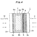
- Fig. 4 is a cross-sectional view showing a construction of the spatial light modulator according to the present invention.
- Fig. 5(A) is a perspective view for explaining aligning directions of liquid crystal molecules of a liquid crystal layer in a first embodiment.
- Fig. 5(B) is a plan view of the liquid crystal layer shown in Fig. 5(A).
- Fig. 6(A) is a graph showing a relation between a first tilt angle ⁇ 1 and a contrast ratio of a light output amount to a light input amount in the first embodiment when a driving electric field is applied and not applied.
- Fig. 6(B) is a graph showing a relation between the second tilt angle ⁇ 2 and the contrast ratio of the light output amount to the light input amount in the first embodiment when a driving electric field is applied (on) and not applied (off).
- Fig. 7 is a graph showing a relation between the contrast ratio of the output light amount to the input light amount and an aligning direction of the first liquid crystal molecule to a polarizing direction of the reading light in the first embodiment, when the driving electric field is varied "on" and "off".
- Fig, 8 is a graph showing a relation between a value of ⁇ n ⁇ d and the contrast ratio of the output light amount to the input light amount in the first embodiment when the supplied electric field is varied on or off.
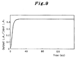
- Fig. 9 is a graph showing a response characteristic of the spatial light modulator 1 of the first embodiment of the present invention, when an electric field is applied to the spatial light modulator.
- Fig. 10(A) is a perspective view for explaining aligning directions of the liquid crystal molecules of a liquid crystal layer in a second embodiment.
- Fig. 10(B) is a plan view the liquid crystal layer shown in of Fig. 10(A).
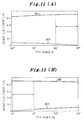
- Fig. 11(A) is a graph showing a relation between the first tilt angle 81 and a contrast ratio of a light output amount to a light input amount in the second embodiment when a driving electric field is applied (on) and not applied (off).
- Fig. 11(B) is a graph showing a relation between the second tilt angle ⁇ 2 and the contrast ratio of the light output amount to the light input amount in the second embodiment when a driving electric field is applied (on) and not applied (off).
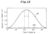
- Fig. 12 is a graph showing a relation between a twisted angel ⁇ and the contrast ratio of the light output amount to the light input amount in the second embodiment when a driving electric field is applied (on) and not applied (off).
- Fig. 13 is a graph showing a relation between the contrast ratio of the output light amount to the input light amount and an angel ⁇ between a polarizing direction of the reading light and an aligning direction ( a long axis direction) of the first liquid crystal molecules 7a in the second embodiment when a driving electric field is varied "on" and "off".
- Fig. 14 is a graph showing a relation between a value of ⁇ n ⁇ d and the contact ratio of the output light amount to the input light amount in the second embodiment when the supplied electric field is varied "on” or “off”, wherein ⁇ n: birefringence anisotropy of the liquid crystal layer and “d" ( ⁇ m): thickness of the liquid crystal layer of the spatial light modulator.
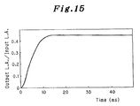
- Fig, 15 is a graph showing a response characteristic of the second embodiment of the present invention when an electric field is applied to the spatial light modulator.
- Fig. 4 is a cross-sectional view showing a construction of the spatial light modulator 1 according to the present invention, wherein like reference characters designate like parts in Fig. 2.
- a first embodiment of a spatial light modulator 1 of the present invention has the same construction as that of the spatial light modulator 10 of the prior art, however, aligning directions of the liquid crystal molecules of the liquid crystal layer 7 are different therefrom. The aligning directions of the liquid crystal molecules will be described thereafter.
- a numeral 1 designates a spatial light modulator according to the present invention, 2a, 2b, transparent substrates disposed in parallel to each other, and 3a, 3b, transparent electrodes disposed between the glass substrates 2a, 2b.
- a photoconductive layer 4 and a reflecting layer 5 are laminated in the order.
- a liquid crystal layer 7 is formed as a cell confined by liquid crystal alignment layers 6a, 6b and spacers 8a, 8b.
- a liquid crystal molecules thereof is filled so as to have different aligning directions from those of the prior art mentioned in the foregoing.
- transparent glass plates are employed as the transparent substrates 2a, 2b, however, transparent resin can be also employed instead of the transparent glass plates.
- the transparent electrodes 3a, 3b are formed of IO2 or SnO2.
- the photoconductive layer 4 formed on the transparent electrode 3b is provided by using such a photoconductive material as hydrogenated amorphous silicon, CdSe, PbS or a compound thereof.
- liquid crystal aligning layers 6a, 6b conventional ones to be used in liquid crystal display elements can be optionally employed considering aligning directions of the liquid crystal molecules of the liquid crystal layer 7.
- a polymer layer as polyimid, polyamid and polyvinyle which cause the liquid crystal molecules to align in a parallel direction to the liquid crystal aligning layer 6a.
- liquid crystal aligning layer 6b provided on the side of the transparent substrate 2b, there is employed long-chain alcohol, silane coupling agent or chromium complex which causes the liquid crystal molecules thereof to align in a perpendicular direction to the liquid crystal aligning layer 6b together with SiO or SiO2 layer previously provided for giving a predetermined pre-tilt angle to the liquid crystal molecules of the liquid crystal layer 7.
- a nematic liquid crystal having a positive or a negative anisotropy of dielectric is used in the present invention.
- fluoro, schiff's base, azo, azoxy, ester, biphenyl, phenyl, cyclohexyl, pyrimidinyl, dioxane fragment and so on are used independently or in a mixed state.
- Fig. 5(A) is a perspective view for explaining aligning directions of the liquid crystal molecules of the liquid crystal layer 7 in the first embodiment.
- Fig. 5(B) is a plan view of Fig. 5(A).
- parts of liquid crystal molecules contacting with the liquid crystal aligning layer 6a in the liquid crystal layer 7 are referred to as a first group of liquid crystal molecules 7a, on the other hand, parts of liquid crystal molecules contacting with the liquid crystal aligning layer 6b is referred to as a second group of liquid crystal molecules 7b.
- a first tilt angle ⁇ 1 made by a long-axis of the liquid crystal molecule in the first group of liquid crystal molecules and the surface of the liquid crystal aligning layer 6a is determined to be within a range from 0° ⁇ 10°
- a second tilt angle ⁇ 2 made by a long-axis of the liquid crystal molecules in the second group of liquid crystal molecules 7b and the surface of the liquid crystal aligning layer 6b is determined to be within a range from 80° ⁇ 90°, wherein the liquid crystal molecules 7a of the first group are aligned in parallel to each other as well as the liquid crystal molecules of the second group.
- a reference character X designates a polarizing direction (or a perpendicular direction to the polarizing direction ) of the polarizing beam splitter 15 and a reference character Y designates the perpendicular direction to the polarizing direction ( or the polarizing direction ) of the polarizing beam splitter 15.
- Fig. 6(A) is a graph showing a relation between a first tilt angle ⁇ 1 and a contrast ratio of a light output amount to a light input amount in the first embodiment when a driving electric field is applied (on) and not applied (off).
- Fig 6(B) is a graph showing a relation between a second tilt angle ⁇ 2 and the contrast ratio of the light output amount to the light input amount when a driving electric field is applied (on) and not applied (off).
- the contrast ratio of the light output amount to the light input amount becomes larger when a range of the first tilt angle ⁇ 1 is made within 0°-10° and a range of the second tilt angle ⁇ 2 is made within 80°-90°. Further, the closer the first and second tilt angles ⁇ 1 and ⁇ 2 respectively come to 0° and 90°, the larger the contrast ratios of them become, however, which poses a reduction of the response speed and invites disclination of liquid crystal molecules.
- the first and second group of liquid crystal molecules 7a and 7b are respectively aligned in parallel in a plan view as shown in Fig. 5(B).
- the liquid crystal layer 7 of the first embodiment has no twisted structure in a thickness direction thereof, i.e, a twist angle ⁇ is approximately 0°, which improves the optical characteristic of the spatial light modulator 1.
- a direction of a polarizing light axis of an incident light which is corresponding to the polarizing axis direction X of the polarizing beam splitter 15 is preferably to be 45° to the long axis of the first group of liquid crystal molecule 7a or is determined at least to be within a range of 30°-60° taking account of the contrast ratio.
- Fig. 7 is a graph showing a relation between the contrast ratio of the output light amount to the input light amount and an angel ⁇ between a polarizing direction of the reading light and an aligning direction ( a long axis direction) of the first group of liquid crystal molecules 7a in the first embodiment when a driving electric field is varied "on" and "off".
- an aligning direction of the first liquid crystal molecule to a polarizing direction of the reading light is preferable to be determined to be within 30° - 60°.
- Fig. 8 is a graph showing a relation between a value of ⁇ n ⁇ d and the contrast ratio of the output light amount to the input light amount in the first embodiment when the supplied electric field is varied on or off, wherein ⁇ n: birefringence anisotropy of the liquid crystal layer 7 and d ( ⁇ m): thickness of the liquid crystal layer 7 of the spatial light modulator 1.
- the ratio of the output light amount to the input light amount shows a high dependency on the value of ⁇ n ⁇ d in the spatial light modulator 1, and it is desirable for the value of ⁇ n ⁇ d to be determined within a range of 0.45 ⁇ m ⁇ 0.75 ⁇ m taking account of the contrast ratio and brightness.
- the second embodiment of the spatial light modulator 1 provided with the liquid crystal layer 7 having features that the value of ⁇ n ⁇ d is made to be within a range of 0.45 ⁇ m - 0.75 ⁇ m, the first tilt angle ⁇ 1 of the first liquid crystal molecules 7a (7b) is made to be within a range of 0°-10°, and the second tilt angle ⁇ 2 of the second liquid crystal molecules 7b (7a) is made to be within a range of 80° ⁇ 90°, when the polarizing direction of the incident light (the reading light 12) is inclined to the aligning direction of the first group of the liquid crystal molecules 7a by an angle within a range of 30° ⁇ 60°.
- a light image generated by, for instance, a CRT impinges on the spatial light modulator 1 as a writing light 11.
- the reading light is irradiated on the spatial light modulator 1 through the polarizing beam splitter 15.
- the reading light which is spatially modulated by the liquid crystal layer 7 passes through the polarizing beam splitter 15 and displayed on the screen 17 through the projection lens 16 as an light image.
- an eternal electric source (not shown) is connected across the transparent electrodes 3a, 3b and an optimum AC driving voltage is applied, wherein the internal impedance of the photoconductive layer 4 is made large enough compared with that of the liquid crystal layer 7, so that the driving voltage is mainly applied to the photoconductive layer 4.
- the internal impedance of the photoconductive layer 4 is partially decreased in correspondence with the brightness and the darkness of the information image, so that the driving voltage is applied to the liquid crystal layer 7 in such a manner that portions of the liquid crystal layer 7 which portions are adjacent to the internal impedance decreased portions thereof are spatially modulated in correspondence with the brightness of the light image, thus, the aligning state of liquid crystal molecules in the liquid crystal layer 7 is changed in correspondence with the voltage increased portions of the liquid crystal layer 7.
- the long-axis directions of the liquid crystal molecules having a positive dielectric anisotropy are aligned to be approximately perpendicular to the liquid crystal aligning layers 6a, 6b.
- the first tilt angle ⁇ 1 initially given to the long-axis of the fist group of liquid crystal molecules 7a is made as small as 0° ⁇ 10°, thus, the change of tile first tilt angle ⁇ 1 becomes large even though a small voltage is applied to the liquid crystal layer 7, and the tilt angle ⁇ 2 initially given to the long-axis of the fist group of liquid crystal molecules 7b is made as large as 80° ⁇ 90°, thus, the change of the first tilt angle ⁇ 1 becomes small when a small voltage is applied to the liquid crystal layer 7.
- the effective anisotropy of birefringence of the liquid crystal layer 7 changes together with the change of direction of the long axis of the liquid crystal molecule, so that the index of the birefringence of the liquid crystal layer 7 is changed, thus, an output reading light reflected by the reflecting layer 5 and returned through the liquid crystal layer 7 has a different polarization from that of the initial linear polarizing light which is obtained by causing the initial reading light 12 to reflect at right angle by the polarizing beam splitter 15.
- the change of polarization of the reading light allows to obtain a transmitting light passing through the polarizing beam splitter 15.
- a light image having an excellent contrast ratio is projected on the screen 17.
- the information image written in the photoconductive layer 4 diminishes as a time lapses because the alignment state of liquid crystal molecules returns by itself to the initial state when the writing light is removed from irradiation, i.e., utilizing reversible change of alignment of the liquid crystal molecules.
- Table 1 shows exemplary physical conditions and experimental results of the spatial light modulator 1 of the present invention regarding examples 1-4 of the embodiment 1 of the present invention together with the comparative example 1 of the prior art.
- a horizontal axis shows a time lapse and a vertical axis shows the ratio of an output light amount to the incident light amount as mentioned in Fig. 3(A).
- the spatial light modulator 1 of the present invention has a very high speed response characteristic because a required time lapse to obtain a maximum contrast ratio from the initial state, i.e., a writing time is approximately 10 ms.
- a spatial light modulator 1 of the second embodiment of the present invention has basically the same construction as that of the spatial light modulator 1 of the first embodiment as shown in Fig. 4, however, aligning directions of the liquid crystal molecules of the liquid crystal layer 7 in the second embodiment are different from those of the first embodiment, thus, like reference characters designate like parts in Fig. 4 and a detailed description of the construction thereof is omitted for simplicity. Then, the aligning directions of the liquid crystal molecules and differences of the construction will be described hereafter together with the operation and the advantage thereof.
- a nematic liquid crystal having a positive dielectric anisotropy are used in the second embodiment.
- fluoro, schiff's base, azo, azoxy, ester, biphenyl, phenyl, cyclohexyl, pyrimidinyl, dioxane fragment and so on are used indivdually or in a mixed state.
- liquid crystal alignment layers 6a, 6b conventional ones to be used in liquid crystal display elements are optionally used considering aligning directions of the liquid crystal molecules of the liquid crystal layer 7.
- liquid crystal aligning layer 6a provided on the side of the glass substrate 2a
- long-chain alcohol, silane coupling agent or chromium complex which causes the liquid crystal molecules thereof to align in a perpendicular direction to the liquid crystal aligning layer 6a together with SiO or SiO2 layer previously provided for giving a predetermined pre-tilt angle to the liquid crystal molecules of the liquid crystal layer 7.
- liquid crystal aligning layer 6b provided on the side of the glass substrate 2b
- a polymer layer as polyimid, polyamid or polyvinyle which causes the liquid crystal molecules to align in a parallel direction to the liquid crystal aligning layer 6b.
- Fig. 10(A) is a perspective view for explaining aligning directions of the liquid crystal molecules in the second embodiment.
- Fig. 10(B) is a plan view of Fig. 10(A).
- parts of liquid crystal molecules contacting with the liquid crystal aligning layer 6a in the liquid crystal layer 7 is referred to as a first group of liquid crystal molecules 7a on the liquid crystal aligning layer 6a
- parts of liquid crystal molecules contacting with the liquid crystal aligning layer 6b is referred to as a second group of liquid crystal molecules 7b on the liquid crystal aligning layer 6b as mentioned in the foregoing.
- a first tilt angle ⁇ 1 made by a long-axis of each of the first group of liquid crystal molecules 7a and the surface of the liquid crystal aligning layer 6a is determined to be within a range of 80° ⁇ 90° and a second tilt angle ⁇ 2 made by a long-axis of each of the second group of liquid crystal molecules 7b and the surface of the liquid crystal aligning layer 6b is determined within a range from 0° ⁇ 10°, wherein the liquid crystal molecules 7a of the first group are aligned in parallel to each other as well as the liquid crystal molecules of the second group.
- a reference character X designates a polarizing direction (or a direction perpendicular to the polarizing direction) of the polarizing beam splitter 15 and a reference character Y designates a direction perpendicular to the polarizing direction (or a polarizing direction) of the polarizing beam splitter 15.
- Fig. 11(A) is a graph showing a relation between a first tilt angle ⁇ 1 and the contrast ratio of the light output amount to the light input amount in the second embodiment when a driving electric field is applied and not applied.
- Fig. 11(B) is a graph showing a relation between the second tilt angle ⁇ 2 and the contrast ratio of the light output amount to the light input amount when a driving electric field is applied (on) and not applied (off).
- the contrast ratio of the light output amount to the light input amount becomes larger when a range of the first tilt angle ⁇ 1 is made within a range of 80° ⁇ 90° and a range of the second tilt angle ⁇ 2 is made within a range of 0° ⁇ 10°. Further, the contrast ratio of the light output amount to the light input amount becomes larger when a rage of the first tilt angle ⁇ 1 is made within a range of 0° ⁇ 10° and a range of the second tilt angle ⁇ 2 is made within a range from 80° ⁇ 90°. Furthermore, when the closer the first and second tilt angles ⁇ 1 and ⁇ 2 respectively comes to 90° and 0°, the larder the contrast ratios of them become, however, it poses a reduction of the response speed and inviting disclinations of liquid crystal molecules.
- the liquid crystal molecules of the liquid crystal layer 7 form a spiral structure having a twist angle ⁇ in a counterclockwise direction in the thickness direction of the liquid crystal layer 7.
- Fig. 12 is a graph showing a relation between a twisted angel ⁇ and the contrast ratio of the light output amount to the light input amount in the second embodiment when a driving electric field is applied (on) and not applied (off).
- the contrast ratio of the light output amount to a light input amount becomes larger by causing the twisted angle ⁇ to be 40°-50°.
- the liquid crystal aligning layer 6a and the liquid crystal aligning layer 6b is respectively provided on the transparent substrates 2a and 2b in such a manner that an angle made by two lines of aligned directions of the liquid crystal molecules on the liquid crystal aligning layers 6a and 6b becomes within 40° ⁇ 50° on a plan view as shown in Fig. 10 (B).
- axes of the liquid crystal molecules is continuously twisted in the liquid crystal layer 7.
- the twisted angle ⁇ of the liquid crystal molecules can be made stable by an amount and a kind of additives applied in the liquid crystal layer 7.
- Fig. 13 is a graph showing a relation between the ratio of the output light amount to the input light amount and an angel ⁇ between a polarizing direction of the reading light and a aligning direction ( a long axis direction) of the first liquid crystal molecules 7a in the second embodiment when a driving electric field is varied "on" and "off".
- the abovementioned angle ⁇ is defined as an angle made by both lines of directions, the aligning direction of the first liquid crystal molecules 7a on the liquid aligning layer 6a provided on the transparent substrate 2a and the polarizing direction X of a polarized reading light.
- the polarizing direction X of the incident reading light is preferably determined to be parallel to the aligning direction of the first liquid crystal molecules 7a of the first liquid crystal aligning layer 6a or at least within a range of 0° ⁇ ⁇ 5° and a range of 90° ⁇ ⁇ 5° taking account of the contrast ratio and colors of the image.
- the angle ⁇ defined in the foregoing is determined to be at least within a range of 0° ⁇ 5° and a range of 90° ⁇ ⁇ 5°.
- Fig. 14 is a graph showing a relation between a value of ⁇ n ⁇ d and the contrast ratio of the output light amount to the input light amount in the second embodiment when the supplied electric field is varied "on” or "off", wherein ⁇ n: birefringence anisotropy of the liquid crystal layer 7 and d ( ⁇ m): thickness of the liquid crystal layer 7 of the spatial light modulator 1.
- the ratio of the output light amount to the input light amount shows a high dependency on the value of ⁇ n ⁇ d in the spatial light modulator 1, and it is desirable for the value of ⁇ n ⁇ d to be determined within 0.45 ⁇ m ⁇ 0.75 ⁇ m taking account of the contrast ratio and brightness of the light image.
- the second embodiment of the spatial light modulator 1 provided with the liquid crystal layer 7 having features that the value of ⁇ n ⁇ d is made to be within a range of 0.45 ⁇ m ⁇ 0.75 ⁇ m and the first tilt angle ⁇ 1 of the first group of liquid crystal molecules 7a (7b) is made to be within the range of 0°-10° and the second tilt angle ⁇ 2 of the second group of liquid crystal molecules 7b (7a) is made to be within the range of 80° ⁇ 90°, of which the spatial light modulator 1 is irradiated by a polarized reading light by causing a polarizing direction of the reading light ( an incident light)to be inclined to the aligning direction of the first liquid crystal molecules 7a within a range of 0° ⁇ 5°.
- the second embodiment of the spatial light modulator 1 is used in the projector shown in Fig.1 in a the same mariner as that of the first embodiment of the spatial light modulator 1 thus, a description is given only to the operation of the liquid crystal layer 7.
- the long-axis directions of the liquid crystal molecules are aligned to be nearly perpendicular to the transparent substrates 2a, 2b maintaining twisting angles in a range of 40° ⁇ 50°.
- the first tilt angle ⁇ 1 initially given to the long-axis of the fist crystal molecules 7a is made as larger as 80°-90° as mentioned in the foregoing, thus, the change of the first tilt angle ⁇ 1 becomes small even though a large voltage is applied to the liquid crystal layer 7, on the other hand, the second tilt angle ⁇ 2 initially given to the long-axis of the fist crystal molecules 7b is made as small as 0° ⁇ 10°, thus, the change of the second tilt angle ⁇ 2 becomes larger when a small voltage is applied to the liquid crystal layer 7.
- the spatial light modulator 1 loses an initial optical rotary power in accordance with the change of direction of the long axis of the liquid crystal molecule, so that influence of the birefringence is increased, thus, an output reading light reflected by the reflecting layer 5 and returned through the liquid crystal layer 7 is different from the initial linear polarizing light which is obtained by causing the initial reading light 12 to reflect at right angle by the polarizing beam splitter 15, which allows to obtain lights passing through the polarizing beam splitter 15.
- the information image written in the photoconductive layer 4 diminishes as a time lapses because the alignment state of the liquid crystal molecules returns by itself to the initial state when the writing light is removed, i.e., utilizing reversible change of alignment of the liquid crystal molecules.
- Table 2 shows exemplary physical conditions and experimental results of the second embodiment of the spatial light modulator 1 of the present invention regarding examples 5 of the embodiment 2 of the present invention together with the comparative example 2 of the prior art.
- a horizontal axis shows a time lapse and a vertical axis shows the ratio of an output light amount to the incident light amount as mentioned in Fig. 3.
- the second embodiment of the spatial light modulator 1 of the present invention has a very high speed response characteristic because a required time lapse to obtain a maximum contrast ratio from the initial state, i.e., a writing time, is approximately 11 ms.
- the spatial light modulator has a high speed response characteristic, thus, it is advantageous when the spatial light modulator is used for displaying motion image pictures because of enabling to shorten a writing time of the light image therein.
Abstract
Description
- The present invention relates to a spatial light modulator having a photoconductive layer and a photomodulator layer and particularly relates to improvements of a spatial light modulator having a high speed response characteristic and suitable characteristics for projectors.
- Presently, as a display device, there are typically two types, i.e., a direct viewing-type and a projection-type, and the latter is now utilized by employing a spatial light modulator having a liquid crystal as a photomodulator.
- Fig. 1 is a diagram, partially pictorial and partially schematic, of a projector employing a spatial light modulator.
- Referring to Fig. 1. an image information is written in a
spatial light modulator 10 by awriting light 11 generated by a writing light system (not shown). On the other hand, after a light generated by alight source 13 is transformed to a parallel by acondenser lens 14, the parallel light impinges on a polarizingbeam splitter 15. An S-polarized light component of the parallel light is reflected at a right angle by a joint surface (boundary pane) of the polarizingbeam splitter 15 and impinges on a liquid crystal layer of thespatial light modulator 10 as areading light 12. When the information image is written in thespatial light modulator 10, thereading light 12 reflected by the thespatial light modulator 10 contains a P-polarized light component by being modulated in the liquid crystal layer in accordance with the brightness and darkness gradation of the information image. The P-polarized light component of thereflected reading light 12 passes through the polarizingbeam splitter 15 and projected on ascreen 17 as the information image, i.e., the information image, written in thespatial light modulator 10 is projected on thescreen 17. - Fig. 2 is a cross-sectional view showing a spatial light modulator employed in a projector of a prior art.
- Referring to Fig. 2,
spacers 8a and 8b are provided to form a chamber for aliquid crystal layer 9, and liquidcrystal aligning layers 6a, 6b are provided at respective sides of theliquid crystal layer 9. A reflectinglayer 5 of dielectric material are provided at an outside surface of the aligninglayer 6b and aphotoconductive layer 4, for instance, being made of hydrogenerated amorphous silicon (a-Si: H).Transparent electrodes 3a, 3b, for instance, being made of SnO₂ or In₂O₃ are provided at outsides of the alining layer 6a and thephotoconductive layer 4. The overallspatial light modulator 10 has a structure sealed by thetransparent substrates 2a and 2b. - In the
spatial light modulator 10 having such a structure, an AC driving voltage is applied across thetransparent electrodes 3a, 3b onto theliquid crystal layer 9 and thephotoconductive layer 4. The driving voltage is mainly applied to thephotoconductive layer 4 by causing an internal impedance of thephotoconductive layer 4 to be larger than that of theliquid crystal layer 9 in a state where thewriting light 11 is not irradiated. - When the information image is written on the
photoconductive layer 4 by irradiating thewriting light 11, the internal impedance of thephotoconductive layer 4 is partially reduced in accordance with the brightness distribution of the information image, so that the information image is written in theliquid crystal layer 9 in such a manner that the driving voltage applied onto theliquid crystal 9 is changed in accordance with the reduction of the internal impedance of thephotoconductive layer 4, which causes a change of aligning directions of liquid crystal molecules in theliquid crystal layer 9, thus, thereading light 12 passing through theliquid crystal layer 9 is spatially modulated by theliquid crystal layer 9. - Next, a description is given to an aligning direction of the liquid crystal molecules and a polarizing direction of the
reading light 12 in theliquid crystal layer 9 employed in thespatial light modulator 10 of the prior art, - It is well known such a spatial light modulator as using a hybrid field effect mode of a
liquid crystal layer 9 having a 45° twist angle alignment and using an ECB (electrically controlled bifringence) effect by aligning the liquid crystal molecules in a vertical direction or in a horizontal direction in an initial state. A long axis of each of the horizontally aligned liquid crystal molecules in theliquid crystal layer 9 is approximately aligned in parallel to or to have a little pre-tilt angle inclined to thesubstrates 2a, 2b. Further, the liquid crystal molecules of theliquid crystal layer 9 are aligned on the liquidcrystal aligning layers 6a, 6b so as to be parallel each other. - Next, a description is given to a case where the
spatial light modulator 10 having theliquid crystal layer 9 of which molecules are aligned in the horizontal direction is employed in the projector shown in Fig. 1. - When the polarizing
beam splitter 15 is disposed between thespatial light modulator 10 and thelight source 13 in such a manner that a polarizing axis of of the polarizing beam splitter 15 intersects at 45° with the long axis of each of liquid crystal molecules of theliquid crystal layer 9. a retardation (phase delay) R and a phase difference δ occur between an ordinary ray and an extraordinary ray while a lineally polarized incident light passes through theliquid crystal layer 9, which are respectively expressed as

reflected layer 5 and returns back through theliquid crystal layer 9, the retardation R and the phase difference δ occurs again. An intensity (J) of a transmitted light passing through the polarizingbeam splitter 15, which is to be projected on thescreen 17, is expressed using the retardation R and the phase difference δ as follows:
Thus, thespatial light modulator 10 is constructed so that the intensity (J) of the transmission light passing through the polarizingbeam splitter 15 is made small by considering the equation (1) when the driving voltage is not applied to thespatial light modulator 10. - On the other hand, when an electric field is applied across the
transparent electrodes 3a, 3b of thespatial light modulator 10, the liquid crystal molecules each having a positive anisotropy of dielectric characteristic are aligned in an inclined state approximately perpendicular to thetransparent substrates 2a, 2b. Thus, the retardation R is changed because an effective anisotropy of refractive index changes together with the changes of the long axis directions of the liquid crystal molecules of theliquid crystal layer 9, by which the index of birefringence of theliquid crystal layer 9 is changed in accordance with a strength of the electric field of theliquid crystal layer 9, so that a ratio of the P-polarized light to the S-polarized light can be controlled, thus, the intensity of the transmission light passing through the polarizingbeam splitter 15 is controlled or changed so as to reproduce and project the image information on thescreen 17. - Conditions of the abovementioned
spatial light modulator 10 in the prior art are shown in Table 1 as a comparative example 1 (com. 1). - Fig. 3(A) is a graph showing a response characteristic of a comparative example 1 of a spatial light modulator in a prior art when an electric field is applied to the spatial light modulator.
- Referring to Fig. 3(A), a horizontal axis shows a time lapse and a vertical axis shows a ratio of an output light amount to an input light amount, wherein the input light amount designates an amount of a light which impinges on the polarizing
beam splitter 15 and the output light amount designates an amount of a light which is outputted from the polarizingbeam splitter 15. - As mentioned in the foregoing, when an electric field is applied to the
spatial light modulator 10, each of the liquid crystal molecules of theliquid crystal layer 9 comes to a predetermined inclined state to thetransparent substrates 2a, 2b by increasing an angle made by a line of the long axis thereof and thetransparent substrates 2a, 2b. However, until each of the liquid crystal molecules comes to a desired inclined state where a maximum contrast ratio is obtained, it takes 53 ms, in other words, a writing time requires 53 ms, as shown in Fig. 3(A), which poses a difficulty to respond to or follow a speedy motion of a motion picture in a case of displaying the motion picture. - Further, regarding the aligning directions of the liquid crystal molecules in the
liquid crystal layer 9 used in thespatial light modulator 10 and the polarizing direction of the reading light in the prior art, there disclosed in USP 4019807, anotherspatial light modulator 10 using the hybrid field effect mode of theliquid crystal layer 9 employing a 45° twist angle alignment. The liquid crystal molecules of theliquid crystal layer 9 are aligned in such a manner that long-axes of the liquid crystal molecule have slight pre-tilt angles to thetransparent substrates 2a, 2b and to be approximately in parallel to each other in a cross sectional view, taken along a thickness direction of theliquid crystal layer 9. Further the liquid crystal molecules of theliquid crystal layer 9 on the liquidcrystal aligning layer 6a, 6b are respectively aligned in parallel to each other. A 45° twist aligning state of theliquid crystal layer 9 can be obtained by causing the the liquidcrystal aligning layer 6a, 6b to be aligned so that the aligning directions of liquid crystal molecules on the liquidcrystal aligning layers 6a, 6b make an angle of 45°. Thus, axes of the liquid crystal molecules are continuously twisted in theliquid crystal layer 9. - Therefore, when a linear polarized light impinges on the
liquid crystal layer 9 in such a manner that the polarized direction of the polarized light is to be parallel to the long-axes of the liquid crystal molecules, the linear polarization light is rotated by 45° of the twist angle by an optical rotatory power of thecrystal liquid layer 9. - Next, a description is given to a case where the
spatial light modulator 10 having the abovementionedliquid crystal layer 9 having the twist angle of 45° is employed in the projector shown in Fig. 1. - When the polarizing
beam splitter 15 is disposed between thespatial light modulator 10 and thelight source 13 in such a manner that a polarizing axis of of the polarizingbeam splitter 15 is to be parallel to the long axis of each of liquid crystal molecules of theliquid crystal layer 9, an incident light lineally polarized is rotated at an angle of 45° upon passing through theliquid crystal layer 9. However, when the light again passes through theliquid crystal layer 9 by being reflected with the reflectinglayer 5, the reflected light is rotated at an angle of 45° in a reverse direction and resultantly it is polarized in the same polarizing direction as well as the initial incident light, thus the reflected light returns to thelight source 13 by being reflected at a right angle with the joint surface of the polarizingbeam splitter 15. - On the other hand, when an electric field is applied to the
liquid crystal layer 9 across thetransparent electrodes 3a, 3b, the aligned directions of the liquid crystal molecules having a positive anisotropy of dielectric constant are changed so as to approach thetransparent substrates 2a, 2b in a vertical direction thereof, i.e., the liquid crystal molecules are obliquely aligned with thetransparent substrates 2a, 2b in correspondence with a strength of the electric field. When the aligned direction thereof is changed like this, the effective anisotropy of refractive index thereof is changed, which greatly affects the polarization of the polarized light. Thus, the reflected light has no longer the same polarization as that of the initial incident light, and a light image is projected on thescreen 17 because a transmission light passing through thepolarization beam splitter 15 has a distribution of light intensity correspondingly with changed amounts of aligning directions of the liquid crystal molecules. - Conditions of the abovementioned
spatial light modulator 10 in the prior art are shown in Table 2 as a comparative example 2. - Fig. 3(B) is a graph showing a response characteristic of a comparative example 2 of a spatial light modulator in the prior art when an electric field is applied to the spatial light modulator.
- Referring to Fig. 3(b), a horizontal axis shows a time lapse and a vertical axis shows a ratio of an output light amount to an outputted light amount, wherein the input light amount designates an amount of a light which impinges on the polarizing
beam splitter 15 and the outputted light amount designates an amount of a light which is outputted from the polarizingbeam splitter 15. - As mentioned in the foregoing, when an electric field is applied to the
spatial light modulator 10, each of the liquid crystal molecules of theliquid crystal layer 9 comes to a predetermined inclined state by increasing an angle made by the long axis of the liquid crystal molecules and thetransparent substrates 2a, 2b. - However, until each of the liquid crystal molecules comes to a desired inclined state where a maximum contrast ratio is obtained, it takes 32 ms, i.e., a writing time requires 32 ms, as shown in Fig 3(B), which poses a difficulty to respond to or to follow a speedy motion of a motion picture in a case of displaying the motion picture as mentioned in the foregoing.
- Accordingly, a general object of the present invention is to provide a spatial light modulator (valve) in which the above disadvantages have been eliminated.
- More specific object of the present invention is to provide a spatial light modulator having a high speed response characteristic by aligning the liquid crystal molecules in a different way from that of the prior art.
- Another and more specific object of the present invention is to provide a spatial light modulator comprising, a liquid crystal layer interposed between a first and second liquid crystal aligning layer, a light reflecting layer and a photoconductive layer being provided on an outside of the second liquid crystal aligning layer in this order, a pair of transparent electrodes opposing parallel each other provided at outside of the first liquid crystal aligning layer and the photoconductive layer respectively, a pair of transparent substrates opposing parallel each other provided at outsides of the pair of transparent electrodes respectively a first group of liquid crystal molecules in the liquid crystal layer, each having a long-axis, disposed in adjacent to the first liquid crystal aligning layer, a second group of liquid crystal molecules in the liquid crystal layer, each having a long-axis, disposed in adjacent to the second liquid crystal aligning layer, the photoconductive layer being irradiated by a writing light carrying an image information through one of the transparent electrodes for writing the image information thereon, the liquid crystal layer being irradiated by a polarized reading light having a polarizing direction through the other of the transparent electrodes and the first liquid crystal aligning layer, for reading out the image information, the light reflecting layer reflecting the polarized reading light projected out of the liquid crystal layer, wherein the liquid crystal layer comprises, the first group of the liquid crystal molecules being aligned in such a manner that the line of long-axis of the liquid crystal layer intersects, at an angle defined within a range of 30°∼60°, a line of the polarizing direction of the polarized reading light, the liquid crystal layer having a value of Δn · d within a range of 0.45∼0.75 µm, where "Δn" and "d" respectively designates an anisotropy of birefringence of the liquid crystal layer and a thickness of the liquid crystal layer, and one of the first and second groups of the liquid crystal molecules having a tilt angle to the transparent substrates within a range of 0°∼10° and the other thereof have a twist angle thereto within a range of 80°∼90°.
- Other specific object of the present invention is to provide a spatial light modulator comprising, a liquid crystal layer interposed between a first and second liquid crystal aligning layer, a light reflecting layer and a photoconductive layer being provided on a outside of the second liquid crystal aligning layer in this order, a pair of transparent electrodes opposing parallel each other provided at outside of the first liquid crystal aligning layer and the photoconductive layer respectively, a pair of transparent substrates opposing parallel each other provided at outsides of the pair of transparent electrodes respectively, a first group of liquid crystal molecules in the liquid crystal layer, each having a long-axis, disposed in adjacent to the first liquid crystal aligning layer, a second group of liquid crystal molecules in the liquid crystal layer, each having a long-axis, disposed in adjacent to the second liquid crystal aligning layer, the photoconductive layer being irradiated by a writing light carrying an image information through one of the transparent electrodes for writing the image information thereon, the liquid crystal layer being irradiated by a polarized reading light having a polarizing direction through the other of the transparent electrodes and the first liquid crystal aligning layer, for reading out the image information, the light reflecting layer reflecting the polarized reading light projected out of the liquid crystal layer, wherein the liquid crystal layer comprises, the first group of the liquid crystal molecules being aligned in such a manner that the line of long-axis of the liquid crystal layer intersects, at an angle defined within a range of 0°∼ ±5° and a range of 90°- ±5°, a line of the polarizing direction of the polarized reading light, the liquid crystal layer having a value of Δn · d within a range of 0.45∼0.75 µm, where "Δn" and "d" respectively designates an anisotropy of birefringence and a thickness of the liquid crystal layer, one of the first and second group of the liquid crystal molecules having a tilt angle to the transparent substrates within a range of 80°∼90° and the other thereof have a twist angle thereto within a range of 0°∼10°, and the liquid crystal layer having a twisted structure in a direction of the thickness thereof having a twist angle within a range of 40°∼50°.
- Other objects and further features of the present invention will be apparent from the following detailed description.
- Fig. 1 is a diagram, partially pictorial and partially schematic, of a projector employing a spatial light modulator.
- Fig. 2 is a cross-sectional view showing a spatial light modulator employed in a projector of a prior art.
- Fig. 3(A) is a graph showing a response characteristic of a comparative example 1 of a spatial light modulator in a prior art when an electric field is applied to the spatial light modulator.
- Fig. 3(B) is a graph showing a response characteristic of a comparative example 2 of a spatial light modulator in another prior art when an electric field is applied to the spatial light modulator.
- Fig. 4 is a cross-sectional view showing a construction of the spatial light modulator according to the present invention.
- Fig. 5(A) is a perspective view for explaining aligning directions of liquid crystal molecules of a liquid crystal layer in a first embodiment.
- Fig. 5(B) is a plan view of the liquid crystal layer shown in Fig. 5(A).
- Fig. 6(A) is a graph showing a relation between a first tilt angle ϑ1 and a contrast ratio of a light output amount to a light input amount in the first embodiment when a driving electric field is applied and not applied.
- Fig. 6(B) is a graph showing a relation between the second tilt angle ϑ2 and the contrast ratio of the light output amount to the light input amount in the first embodiment when a driving electric field is applied (on) and not applied (off).
- Fig. 7 is a graph showing a relation between the contrast ratio of the output light amount to the input light amount and an aligning direction of the first liquid crystal molecule to a polarizing direction of the reading light in the first embodiment, when the driving electric field is varied "on" and "off".
- Fig, 8 is a graph showing a relation between a value of Δn·d and the contrast ratio of the output light amount to the input light amount in the first embodiment when the supplied electric field is varied on or off.
- Fig. 9 is a graph showing a response characteristic of the spatial
light modulator 1 of the first embodiment of the present invention, when an electric field is applied to the spatial light modulator. - Fig. 10(A) is a perspective view for explaining aligning directions of the liquid crystal molecules of a liquid crystal layer in a second embodiment.
- Fig. 10(B) is a plan view the liquid crystal layer shown in of Fig. 10(A).
- Fig. 11(A) is a graph showing a relation between the
first tilt angle 81 and a contrast ratio of a light output amount to a light input amount in the second embodiment when a driving electric field is applied (on) and not applied (off). - Fig. 11(B) is a graph showing a relation between the second tilt angle ϑ2 and the contrast ratio of the light output amount to the light input amount in the second embodiment when a driving electric field is applied (on) and not applied (off).
- Fig. 12 is a graph showing a relation between a twisted angel φ and the contrast ratio of the light output amount to the light input amount in the second embodiment when a driving electric field is applied (on) and not applied (off).
- Fig. 13 is a graph showing a relation between the contrast ratio of the output light amount to the input light amount and an angel Ψ between a polarizing direction of the reading light and an aligning direction ( a long axis direction) of the first
liquid crystal molecules 7a in the second embodiment when a driving electric field is varied "on" and "off". - Fig. 14 is a graph showing a relation between a value of Δn·d and the contact ratio of the output light amount to the input light amount in the second embodiment when the supplied electric field is varied "on" or "off", wherein Δn: birefringence anisotropy of the liquid crystal layer and "d" (µm): thickness of the liquid crystal layer of the spatial light modulator.
- Fig, 15 is a graph showing a response characteristic of the second embodiment of the present invention when an electric field is applied to the spatial light modulator.
- A first and second embodiments of a spatial light modulator according to the present invention will be described with reference to the
drawings 4 through 15. - Fig. 4 is a cross-sectional view showing a construction of the spatial
light modulator 1 according to the present invention, wherein like reference characters designate like parts in Fig. 2. - A first embodiment of a spatial
light modulator 1 of the present invention has the same construction as that of the spatiallight modulator 10 of the prior art, however, aligning directions of the liquid crystal molecules of theliquid crystal layer 7 are different therefrom. The aligning directions of the liquid crystal molecules will be described thereafter. - Referring to Fig. 4, a
numeral 1 designates a spatial light modulator according to the present invention, 2a, 2b, transparent substrates disposed in parallel to each other, and 3a, 3b, transparent electrodes disposed between theglass substrates 2a, 2b. At a side of thetransparent electrode 3b through which awriting light 11 impinges in a direction of an arrow F1, aphotoconductive layer 4 and a reflectinglayer 5 are laminated in the order. - At another side of the transparent electrode 2a on which a
reading light 12 impinges in a direction of an arrow F2, aliquid crystal layer 7 is formed as a cell confined by liquidcrystal alignment layers 6a, 6b andspacers 8a, 8b. In theliquid crystal layer 7, a liquid crystal molecules thereof is filled so as to have different aligning directions from those of the prior art mentioned in the foregoing. - In this embodiment, transparent glass plates are employed as the
transparent substrates 2a, 2b, however, transparent resin can be also employed instead of the transparent glass plates. - Generally, the
transparent electrodes 3a, 3b are formed of IO₂ or SnO₂. Thephotoconductive layer 4 formed on thetransparent electrode 3b is provided by using such a photoconductive material as hydrogenated amorphous silicon, CdSe, PbS or a compound thereof. As the reflectinglayer 5 stacked on thephotoconductive layer 4, such a multiple layer as zinc sulfide (ZnS), magnesium fluoride (MgF₂), silicon oxide (SiO) or silicon dioxide (SiO₂) is employed. - Further, as the liquid
crystal aligning layers 6a, 6b, conventional ones to be used in liquid crystal display elements can be optionally employed considering aligning directions of the liquid crystal molecules of theliquid crystal layer 7. In this embodiment, as the liquid crystal aligning layer 6a provided on the side of the transparent substrate 2a, there is employed such a polymer layer as polyimid, polyamid and polyvinyle which cause the liquid crystal molecules to align in a parallel direction to the liquid crystal aligning layer 6a. On the other hand, as the liquidcrystal aligning layer 6b provided on the side of thetransparent substrate 2b, there is employed long-chain alcohol, silane coupling agent or chromium complex which causes the liquid crystal molecules thereof to align in a perpendicular direction to the liquidcrystal aligning layer 6b together with SiO or SiO₂ layer previously provided for giving a predetermined pre-tilt angle to the liquid crystal molecules of theliquid crystal layer 7. - Next, a detailed description is given to the
liquid crystal layer 7 of the present invention. - As a material of the
liquid crystal layer 7, a nematic liquid crystal having a positive or a negative anisotropy of dielectric is used in the present invention. For instance, fluoro, schiff's base, azo, azoxy, ester, biphenyl, phenyl, cyclohexyl, pyrimidinyl, dioxane fragment and so on are used independently or in a mixed state. - Further, a description is given to the aligning direction of the
liquid crystal layer 7 in accompany with Figs. 5(A) and 5(B). - Fig. 5(A) is a perspective view for explaining aligning directions of the liquid crystal molecules of the
liquid crystal layer 7 in the first embodiment. - Fig. 5(B) is a plan view of Fig. 5(A).
- Referring to Fig.5 (A), parts of liquid crystal molecules contacting with the liquid crystal aligning layer 6a in the
liquid crystal layer 7 are referred to as a first group ofliquid crystal molecules 7a, on the other hand, parts of liquid crystal molecules contacting with the liquidcrystal aligning layer 6b is referred to as a second group ofliquid crystal molecules 7b. - In this embodiment, a first tilt angle ϑ1 made by a long-axis of the liquid crystal molecule in the first group of liquid crystal molecules and the surface of the liquid crystal aligning layer 6a is determined to be within a range from 0°∼ 10°,and a second tilt angle ϑ2 made by a long-axis of the liquid crystal molecules in the second group of
liquid crystal molecules 7b and the surface of the liquidcrystal aligning layer 6b is determined to be within a range from 80°∼ 90°, wherein theliquid crystal molecules 7a of the first group are aligned in parallel to each other as well as the liquid crystal molecules of the second group. - It is noted that in Figs, 5 (A) and 5 (B), a reference character X designates a polarizing direction (or a perpendicular direction to the polarizing direction ) of the
polarizing beam splitter 15 and a reference character Y designates the perpendicular direction to the polarizing direction ( or the polarizing direction ) of thepolarizing beam splitter 15. - Fig. 6(A) is a graph showing a relation between a first tilt angle ϑ1 and a contrast ratio of a light output amount to a light input amount in the first embodiment when a driving electric field is applied (on) and not applied (off).
- Fig 6(B) is a graph showing a relation between a second tilt angle ϑ2 and the contrast ratio of the light output amount to the light input amount when a driving electric field is applied (on) and not applied (off).
- As will be understood from Figs. 6(A) and 6(B), the contrast ratio of the light output amount to the light input amount becomes larger when a range of the first tilt angle ϑ1 is made within 0°-10° and a range of the second tilt angle ϑ2 is made within 80°-90°. Further, the closer the first and second tilt angles ϑ1 and ϑ2 respectively come to 0° and 90°, the larger the contrast ratios of them become, however, which poses a reduction of the response speed and invites disclination of liquid crystal molecules.
- Further, the first and second group of
liquid crystal molecules liquid crystal layer 7 of the first embodiment has no twisted structure in a thickness direction thereof, i.e, a twist angle φ is approximately 0°, which improves the optical characteristic of the spatiallight modulator 1. Further, a direction of a polarizing light axis of an incident light which is corresponding to the polarizing axis direction X of thepolarizing beam splitter 15 is preferably to be 45° to the long axis of the first group ofliquid crystal molecule 7a or is determined at least to be within a range of 30°-60° taking account of the contrast ratio. - Fig. 7 is a graph showing a relation between the contrast ratio of the output light amount to the input light amount and an angel Ψ between a polarizing direction of the reading light and an aligning direction ( a long axis direction) of the first group of
liquid crystal molecules 7a in the first embodiment when a driving electric field is varied "on" and "off". - Referring to Fig. 7, it will be understood that in order to obtain the large contrast ratio, an aligning direction of the first liquid crystal molecule to a polarizing direction of the reading light is preferable to be determined to be within 30° - 60°.
- Fig. 8 is a graph showing a relation between a value of Δn·d and the contrast ratio of the output light amount to the input light amount in the first embodiment when the supplied electric field is varied on or off, wherein Δn: birefringence anisotropy of the
liquid crystal layer 7 and d (µm): thickness of theliquid crystal layer 7 of the spatiallight modulator 1. - As clearly understood from Fig. 8, the ratio of the output light amount to the input light amount shows a high dependency on the value of Δn·d in the spatial
light modulator 1, and it is desirable for the value of Δn·d to be determined within a range of 0.45 µm ∼ 0.75 µm taking account of the contrast ratio and brightness. - As a component of the projector shown in Fig. 1, there is employed in the projector the second embodiment of the spatial
light modulator 1 provided with theliquid crystal layer 7 having features that the value of Δn·d is made to be within a range of 0.45 µm - 0.75 µm, the first tilt angle ϑ1 of the firstliquid crystal molecules 7a (7b) is made to be within a range of 0°-10°, and the second tilt angle ϑ2 of the secondliquid crystal molecules 7b (7a) is made to be within a range of 80°∼90°, when the polarizing direction of the incident light (the reading light 12) is inclined to the aligning direction of the first group of theliquid crystal molecules 7a by an angle within a range of 30°∼60°. - Next, a description is given to an operation of the spatial
light modulator 1. - Generally, in the abovementioned projector, a light image generated by, for instance, a CRT impinges on the spatial
light modulator 1 as a writinglight 11. On the other hand, after a light generated by thelight source 13 is made a parallel light through thecondenser lens 14 as the reading light, the reading light is irradiated on the spatiallight modulator 1 through thepolarizing beam splitter 15. After reflected by the reflectinglayer 5, the reading light which is spatially modulated by theliquid crystal layer 7 passes through thepolarizing beam splitter 15 and displayed on thescreen 17 through theprojection lens 16 as an light image. - Further, referring to Fig, 4, an eternal electric source (not shown) is connected across the
transparent electrodes 3a, 3b and an optimum AC driving voltage is applied, wherein the internal impedance of thephotoconductive layer 4 is made large enough compared with that of theliquid crystal layer 7, so that the driving voltage is mainly applied to thephotoconductive layer 4. - When the writing
light 11 caring image information is irradiated on the spatiallight modulator 1 and the information image is written on thephotoconductive layer 4 by the writinglight 11, the internal impedance of thephotoconductive layer 4 is partially decreased in correspondence with the brightness and the darkness of the information image, so that the driving voltage is applied to theliquid crystal layer 7 in such a manner that portions of theliquid crystal layer 7 which portions are adjacent to the internal impedance decreased portions thereof are spatially modulated in correspondence with the brightness of the light image, thus, the aligning state of liquid crystal molecules in theliquid crystal layer 7 is changed in correspondence with the voltage increased portions of theliquid crystal layer 7. - When the applied voltage to the
liquid crystal layer 7 is increased, the long-axis directions of the liquid crystal molecules having a positive dielectric anisotropy are aligned to be approximately perpendicular to the liquidcrystal aligning layers 6a, 6b. In other words, the first tilt angle ϑ1 initially given to the long-axis of the fist group ofliquid crystal molecules 7a is made as small as 0°∼10°, thus, the change of tile first tilt angle ϑ1 becomes large even though a small voltage is applied to theliquid crystal layer 7, and the tilt angle ϑ2 initially given to the long-axis of the fist group ofliquid crystal molecules 7b is made as large as 80°∼90°, thus, the change of the first tilt angle ϑ1 becomes small when a small voltage is applied to theliquid crystal layer 7. In this state of the spatiallight modulator 1, the effective anisotropy of birefringence of theliquid crystal layer 7 changes together with the change of direction of the long axis of the liquid crystal molecule, so that the index of the birefringence of theliquid crystal layer 7 is changed, thus, an output reading light reflected by the reflectinglayer 5 and returned through theliquid crystal layer 7 has a different polarization from that of the initial linear polarizing light which is obtained by causing theinitial reading light 12 to reflect at right angle by thepolarizing beam splitter 15. The change of polarization of the reading light allows to obtain a transmitting light passing through thepolarizing beam splitter 15. Thus, a light image having an excellent contrast ratio is projected on thescreen 17. - In this spatial
light modulator 1, the information image written in thephotoconductive layer 4 diminishes as a time lapses because the alignment state of liquid crystal molecules returns by itself to the initial state when the writing light is removed from irradiation, i.e., utilizing reversible change of alignment of the liquid crystal molecules. - Table 1 shows exemplary physical conditions and experimental results of the spatial
light modulator 1 of the present invention regarding examples 1-4 of theembodiment 1 of the present invention together with the comparative example 1 of the prior art.
- Wherein (1)-(10) denote as follows:
- (1) thickness (d) of the liquid crystal layer (µm)
- (2) anisotropy of the refractive index of liquid crystal molecule (Δn)
- (3) anisotropy of the dielectricity of liquid crystal molecule (Δε)
- (4) tilt angle ϑ1 (degree) of the first
liquid crystal molecules 7a on the transparent substrate 2a - (5) tilt angle ϑ2 (degree) of the second
liquid crystal molecules 7a on thetransparent substrate 2b - (6) twist angle ψ (degree) of the liquid crystal molecules
- (7) angel φ (degree) between the polarizing direction of the reading light and an aligning direction (a long axis direction) of the first
liquid crystal molecules 7a - (8) applied voltage (V) to the liquid crystal layer
- (9) response time (ms) of the spatial light modulator
- (10) corresponding Figures
- Referring to Fig. 9, a horizontal axis shows a time lapse and a vertical axis shows the ratio of an output light amount to the incident light amount as mentioned in Fig. 3(A).
- As clearly understood from Fig. 9, the spatial
light modulator 1 of the present invention has a very high speed response characteristic because a required time lapse to obtain a maximum contrast ratio from the initial state, i.e., a writing time is approximately 10 ms. - A second embodiment of a spatial
light modulator 1 according to the present invention will be described with reference to the drawings. - A spatial
light modulator 1 of the second embodiment of the present invention has basically the same construction as that of the spatiallight modulator 1 of the first embodiment as shown in Fig. 4, however, aligning directions of the liquid crystal molecules of theliquid crystal layer 7 in the second embodiment are different from those of the first embodiment, thus, like reference characters designate like parts in Fig. 4 and a detailed description of the construction thereof is omitted for simplicity. Then, the aligning directions of the liquid crystal molecules and differences of the construction will be described hereafter together with the operation and the advantage thereof. - At first, a detailed description is given to the
liquid crystal layer 7 of the second embodiment. - As materials of the
liquid crystal layer 7, a nematic liquid crystal having a positive dielectric anisotropy are used in the second embodiment. For instance, fluoro, schiff's base, azo, azoxy, ester, biphenyl, phenyl, cyclohexyl, pyrimidinyl, dioxane fragment and so on are used indivdually or in a mixed state. - Further, as the liquid
crystal alignment layers 6a, 6b, conventional ones to be used in liquid crystal display elements are optionally used considering aligning directions of the liquid crystal molecules of theliquid crystal layer 7. - In this embodiment, as the liquid crystal aligning layer 6a provided on the side of the glass substrate 2a, there is employed long-chain alcohol, silane coupling agent or chromium complex which causes the liquid crystal molecules thereof to align in a perpendicular direction to the liquid crystal aligning layer 6a together with SiO or SiO₂ layer previously provided for giving a predetermined pre-tilt angle to the liquid crystal molecules of the
liquid crystal layer 7. On the other hand, as the liquidcrystal aligning layer 6b provided on the side of theglass substrate 2b, there is employed such a polymer layer as polyimid, polyamid or polyvinyle which causes the liquid crystal molecules to align in a parallel direction to the liquidcrystal aligning layer 6b. - Further, a description is given to the aligning direction of the
liquid crystal layer 7 by accompanying Figs. 10(A) and 10(B). - Fig. 10(A) is a perspective view for explaining aligning directions of the liquid crystal molecules in the second embodiment.
- Fig. 10(B) is a plan view of Fig. 10(A).
- Referring to Fig. 10(A), parts of liquid crystal molecules contacting with the liquid crystal aligning layer 6a in the
liquid crystal layer 7 is referred to as a first group ofliquid crystal molecules 7a on the liquid crystal aligning layer 6a, on the other hand, parts of liquid crystal molecules contacting with the liquidcrystal aligning layer 6b is referred to as a second group ofliquid crystal molecules 7b on the liquidcrystal aligning layer 6b as mentioned in the foregoing. Thus, a first tilt angle ϑ1 made by a long-axis of each of the first group ofliquid crystal molecules 7a and the surface of the liquid crystal aligning layer 6a is determined to be within a range of 80°∼90° and a second tilt angle ϑ2 made by a long-axis of each of the second group ofliquid crystal molecules 7b and the surface of the liquidcrystal aligning layer 6b is determined within a range from 0°∼10°, wherein theliquid crystal molecules 7a of the first group are aligned in parallel to each other as well as the liquid crystal molecules of the second group. - It is noted that in Figs. 10 (A) and 10 (B), a reference character X designates a polarizing direction (or a direction perpendicular to the polarizing direction) of the
polarizing beam splitter 15 and a reference character Y designates a direction perpendicular to the polarizing direction (or a polarizing direction) of thepolarizing beam splitter 15. - Fig. 11(A) is a graph showing a relation between a first tilt angle ϑ1 and the contrast ratio of the light output amount to the light input amount in the second embodiment when a driving electric field is applied and not applied.
- Fig. 11(B) is a graph showing a relation between the second tilt angle ϑ2 and the contrast ratio of the light output amount to the light input amount when a driving electric field is applied (on) and not applied (off).
- As will be understood from Figs. 11(A) and 11(B), the contrast ratio of the light output amount to the light input amount becomes larger when a range of the first tilt angle ϑ1 is made within a range of 80°∼90° and a range of the second tilt angle ϑ2 is made within a range of 0°∼10°. Further, the contrast ratio of the light output amount to the light input amount becomes larger when a rage of the first tilt angle ϑ1 is made within a range of 0°∼10° and a range of the second tilt angle ϑ2 is made within a range from 80°∼90°. Furthermore, when the closer the first and second tilt angles ϑ1 and ϑ2 respectively comes to 90° and 0°, the larder the contrast ratios of them become, however, it poses a reduction of the response speed and inviting disclinations of liquid crystal molecules.
- Referring to Fig. 10(B), there is shown a twisted angle φ between the first group of the
liquid crystal molecules 7a on the liquid crystal aligning layer 6a and the second group ofliquid crystal molecules 7b on the liquidcrystal aligning layer 6b. In other words, the liquid crystal molecules of theliquid crystal layer 7 form a spiral structure having a twist angle φ in a counterclockwise direction in the thickness direction of theliquid crystal layer 7. - Fig. 12 is a graph showing a relation between a twisted angel φ and the contrast ratio of the light output amount to the light input amount in the second embodiment when a driving electric field is applied (on) and not applied (off).
- Referring to Fig. 12, it will be understood that the contrast ratio of the light output amount to a light input amount becomes larger by causing the twisted angle φ to be 40°-50°. In order to make the twisted angle φ to be 40°-50°, the liquid crystal aligning layer 6a and the liquid
crystal aligning layer 6b is respectively provided on thetransparent substrates 2a and 2b in such a manner that an angle made by two lines of aligned directions of the liquid crystal molecules on the liquidcrystal aligning layers 6a and 6b becomes within 40°∼50° on a plan view as shown in Fig. 10 (B). Thus, axes of the liquid crystal molecules is continuously twisted in theliquid crystal layer 7. The twisted angle φ of the liquid crystal molecules can be made stable by an amount and a kind of additives applied in theliquid crystal layer 7. - Fig. 13 is a graph showing a relation between the ratio of the output light amount to the input light amount and an angel Ψ between a polarizing direction of the reading light and a aligning direction ( a long axis direction) of the first
liquid crystal molecules 7a in the second embodiment when a driving electric field is varied "on" and "off". - Referring to Fig, 10(B), the abovementioned angle ψ is defined as an angle made by both lines of directions, the aligning direction of the first
liquid crystal molecules 7a on the liquid aligning layer 6a provided on the transparent substrate 2a and the polarizing direction X of a polarized reading light. - In this embodiment, as will be understood from Fig. 13, the polarizing direction X of the incident reading light is preferably determined to be parallel to the aligning direction of the first
liquid crystal molecules 7a of the first liquid crystal aligning layer 6a or at least within a range of 0°∼ ± 5° and a range of 90°∼ ± 5° taking account of the contrast ratio and colors of the image. In other words, the angle ψ defined in the foregoing is determined to be at least within a range of 0°∼± 5° and a range of 90°∼ ± 5°. - Fig. 14 is a graph showing a relation between a value of Δn·d and the contrast ratio of the output light amount to the input light amount in the second embodiment when the supplied electric field is varied "on" or "off", wherein Δn: birefringence anisotropy of the
liquid crystal layer 7 and d (µm): thickness of theliquid crystal layer 7 of the spatiallight modulator 1. - As clearly understood from Fig. 14, the ratio of the output light amount to the input light amount shows a high dependency on the value of Δn·d in the spatial
light modulator 1, and it is desirable for the value of Δn·d to be determined within 0.45 µm ∼ 0.75 µm taking account of the contrast ratio and brightness of the light image. - As a component of the projector shown in Fig. 1, there is employed in the projector the second embodiment of the spatial
light modulator 1 provided with theliquid crystal layer 7 having features that the value of Δn·d is made to be within a range of 0.45 µm ∼ 0.75 µm and the first tilt angle ϑ1 of the first group ofliquid crystal molecules 7a (7b) is made to be within the range of 0°-10° and the second tilt angle ϑ2 of the second group ofliquid crystal molecules 7b (7a) is made to be within the range of 80°∼90°, of which the spatiallight modulator 1 is irradiated by a polarized reading light by causing a polarizing direction of the reading light ( an incident light)to be inclined to the aligning direction of the firstliquid crystal molecules 7a within a range of 0°∼± 5°. - Next, a description is given to an operation of the second embodiment of the spatial
light modulator 1. - Basically, the second embodiment of the spatial
light modulator 1 is used in the projector shown in Fig.1 in a the same mariner as that of the first embodiment of the spatiallight modulator 1 thus, a description is given only to the operation of theliquid crystal layer 7. - When the applied voltage to the
liquid crystal layer 7 is increased, the long-axis directions of the liquid crystal molecules, each having positive dielectric anisotropy, are aligned to be nearly perpendicular to thetransparent substrates 2a, 2b maintaining twisting angles in a range of 40°∼50°. In other words, the first tilt angle ϑ1 initially given to the long-axis of thefist crystal molecules 7a is made as larger as 80°-90° as mentioned in the foregoing, thus, the change of the first tilt angle ϑ1 becomes small even though a large voltage is applied to theliquid crystal layer 7, on the other hand, the second tilt angle ϑ2 initially given to the long-axis of thefist crystal molecules 7b is made as small as 0°∼10°, thus, the change of the second tilt angle ϑ2 becomes larger when a small voltage is applied to theliquid crystal layer 7. In this state, the spatiallight modulator 1 loses an initial optical rotary power in accordance with the change of direction of the long axis of the liquid crystal molecule, so that influence of the birefringence is increased, thus, an output reading light reflected by the reflectinglayer 5 and returned through theliquid crystal layer 7 is different from the initial linear polarizing light which is obtained by causing theinitial reading light 12 to reflect at right angle by thepolarizing beam splitter 15, which allows to obtain lights passing through thepolarizing beam splitter 15. - In this spatial
light modulator 1, the information image written in thephotoconductive layer 4 diminishes as a time lapses because the alignment state of the liquid crystal molecules returns by itself to the initial state when the writing light is removed, i.e., utilizing reversible change of alignment of the liquid crystal molecules. - Table 2 shows exemplary physical conditions and experimental results of the second embodiment of the spatial
light modulator 1 of the present invention regarding examples 5 of the embodiment 2 of the present invention together with the comparative example 2 of the prior art.
- Wherein (1)-(10) denote as follows:
- (1) thickness (d) of the liquid crystal layer (µm)
- (2) anisotropy of the refractive index of liquid crystal molecule (Δn)
- (3) anisotropy of dielectricity of the liquid crystal molecule (Δε)
- (4) tilt angle ϑ1 (degree) of the first
liquid crystal molecules 7a on the transparent substrate 2a - (5) tilt angle ϑ2 (degree) of the second
liquid crystal molecules 7a on thetransparent substrate 2b - (6) twist angle ψ (degree) of the liquid crystal molecules
- (7) angel φ (degree) between the polarizing direction of the reading light and the aligning direction (a long axis direction) of the first
liquid crystal molecules 7a - (8) applied voltage (V) to the liquid crystal layer
- (9) response time (ms) of the spatial light modulator
- (10) corresponding Figures
- Referring to Fig. 15. a horizontal axis shows a time lapse and a vertical axis shows the ratio of an output light amount to the incident light amount as mentioned in Fig. 3.
- As clearly understood from Fig. 15, the second embodiment of the spatial
light modulator 1 of the present invention has a very high speed response characteristic because a required time lapse to obtain a maximum contrast ratio from the initial state, i.e., a writing time, is approximately 11 ms. - In the second embodiment, the description is given to an example in which liquid crystal molecules of the
liquid crystal layer 7 have a spiral structure of the twist angle φ in a counterclockwise direction, however, other example having a spiral structure of the twist angle φ in a clockwise direction can be employed as well as the former example. - According to the present invention, the spatial light modulator has a high speed response characteristic, thus, it is advantageous when the spatial light modulator is used for displaying motion image pictures because of enabling to shorten a writing time of the light image therein.
- While the presently preferred embodiments of the present invention have been shown and described, it is to be understood these disclosures are for the purpose of illustration and that various changes and modification may be made without departing from the scope of the invention as set forth in the appended claims.
Claims (2)
- A spatial light modulator comprising:
a liquid crystal layer interposed between a first and second liquid crystal aligning layer;
a light reflecting layer and a photoconductive layer being provided on a outside of the second liquid crystal aligning layer in this order;
a pair of transparent electrodes opposing parallel each other provided at outside of the first liquid crystal aligning layer and the photoconductive layer respectively;
a pair of transparent substrates opposing parallel each other provided at outsides of the pair of transparent electrodes respectively;
a first group of liquid crystal molecules in the liquid crystal layer, each having a long-axis, disposed in adjacent to the first liquid crystal aligning layer:
a second group of liquid crystal molecules in the liquid crystal layer, each having a long-axis, disposed in adjacent to the second liquid crystal aligning layer, the photoconductive layer being irradiated by a writing light carrying an image information through one of the transparent electrodes for writing the image information thereon, the liquid crystal layer being irradiated by a polarized reading light having a polarizing direction through the other of the transparent electrodes and the first liquid crystal aligning layer for reading out the image information, the light reflecting layer reflecting the polarized reading light projected out of the liquid crystal layer,
wherein the liquid crystal layer comprises:
the first group of the liquid crystal molecules being aligned in such a manner that the line of long-axis of the liquid crystal layer intersects, at an angle defined within a range of 30°-60°, a line of the polarizing direction of the polarized reading light;
the liquid crystal layer having a value of Δn · d within a range of 0.45∼0.75 µm, where "Δn" and "d" respectively designates an anisotropy of birefringence of the liquid crystal layer and a thickness of the liquid crystal layer; and
one of the first and second groups of the liquid crystal molecules having a tilt angle to the transparent substrates within a range of 0°∼10° and the other thereof have a twist angle thereto within a range of 80°∼90°. - A spatial light modulator comprising:
a liquid crystal layer interposed between a first and second liquid crystal aligning layer;
a light reflecting layer and a photoconductive layer being provided on a outside of the second liquid crystal aligning layer in this order;
a pair of transparent electrodes opposing parallel each other provided at outside of the first liquid crystal aligning layer and the photoconductive layer respectively;
a pair of transparent substrates opposing parallel each other provided at outsides of the pair of transparent electrodes respectively;
a first group of liquid crystal molecules in the liquid crystal layer, each having a long-axis, disposed in adjacent to the first liquid crystal aligning layer;
a second group of liquid crystal molecules in the liquid crystal layer, each having a long-axis, disposed in adjacent to the second liquid crystal aligning layer, the photoconductive layer being irradiated by a writing light carrying an image information through one of the transparent electrodes for writing the image information thereon, the liquid crystal layer being irradiated by a polarized reading light having a polarizing direction through the other of the transparent electrodes and the first liquid crystal aligning layer for reading out the image information, the light reflecting layer reflecting the polarized reading light projected out of the liquid crystal layer,
wherein the liquid crystal layer comprises;
the first group of the liquid crystal molecules being aligned in such a manner that the line of long-axis of the liquid crystal layer intersects, at an angle defined within a range of 0°∼ ±5° and a range of 90°∼±5°, a line of the polarizing direction of the polarized reading light;
the liquid crystal layer having a value of Δn · d within a range of 0.45∼0.75 µm, where "Δn" and "d" respectively designates an anisotropy of birefringence and a thickness of the liquid crystal layer;
one of the first and second group of the liquid crystal molecules having a tilt angle to the transparent substrates within a range of 80°-90° and the other thereof have a twist angle thereto within a range of 0°∼10°; and
the liquid crystal layer having a twisted structure in a direction of the thickness thereof having a twist angle within a range of 40°-50°.
Applications Claiming Priority (4)
| Application Number | Priority Date | Filing Date | Title |
|---|---|---|---|
| JP338161/92 | 1992-11-25 | ||
| JP33816192A JPH06160890A (en) | 1992-11-25 | 1992-11-25 | Optical modulation element |
| JP32710/93 | 1993-01-28 | ||
| JP3271093A JPH06230409A (en) | 1993-01-28 | 1993-01-28 | Optical modulation element |
Publications (2)
| Publication Number | Publication Date |
|---|---|
| EP0600541A1 true EP0600541A1 (en) | 1994-06-08 |
| EP0600541B1 EP0600541B1 (en) | 1997-07-30 |
Family
ID=26371294
Family Applications (1)
| Application Number | Title | Priority Date | Filing Date |
|---|---|---|---|
| EP19930203289 Expired - Lifetime EP0600541B1 (en) | 1992-11-25 | 1993-11-24 | Spatial light modulator |
Country Status (2)
| Country | Link |
|---|---|
| EP (1) | EP0600541B1 (en) |
| DE (1) | DE69312650T2 (en) |
Cited By (2)
| Publication number | Priority date | Publication date | Assignee | Title |
|---|---|---|---|---|
| GB2314640A (en) * | 1996-06-26 | 1998-01-07 | Sharp Kk | Liquid crystal devices |
| GB2314641A (en) * | 1996-06-26 | 1998-01-07 | Sharp Kk | Liquid crystal devices |
Citations (3)
| Publication number | Priority date | Publication date | Assignee | Title |
|---|---|---|---|---|
| GB227853A (en) * | 1924-01-17 | 1925-08-06 | Georges Leon Emile Patart | Improvements in devices for simultaneously effecting the compression and the circulation of gaseous mixtures |
| US4019807A (en) * | 1976-03-08 | 1977-04-26 | Hughes Aircraft Company | Reflective liquid crystal light valve with hybrid field effect mode |
| WO1989008862A1 (en) * | 1988-03-14 | 1989-09-21 | Hughes Aircraft Company | Light valves with positive dielectric anisotropy liquid crystal and highly tilted off-perpendicular surface alignment, and associated operating method |
-
1993
- 1993-11-24 DE DE1993612650 patent/DE69312650T2/en not_active Expired - Fee Related
- 1993-11-24 EP EP19930203289 patent/EP0600541B1/en not_active Expired - Lifetime
Patent Citations (3)
| Publication number | Priority date | Publication date | Assignee | Title |
|---|---|---|---|---|
| GB227853A (en) * | 1924-01-17 | 1925-08-06 | Georges Leon Emile Patart | Improvements in devices for simultaneously effecting the compression and the circulation of gaseous mixtures |
| US4019807A (en) * | 1976-03-08 | 1977-04-26 | Hughes Aircraft Company | Reflective liquid crystal light valve with hybrid field effect mode |
| WO1989008862A1 (en) * | 1988-03-14 | 1989-09-21 | Hughes Aircraft Company | Light valves with positive dielectric anisotropy liquid crystal and highly tilted off-perpendicular surface alignment, and associated operating method |
Non-Patent Citations (3)
| Title |
|---|
| E.ANTOLINI & AL: "ELECTRO-OPTICS OF THE HYBRID NEMATIC CELL", MOLECULAR CRYSTALS AND LIQUID CRYSTALS, LETTERS - SERIES 2, vol. 127, no. 1/4, 1985, READING GB, pages 215 - 227 * |
| M.R.LEWIS: "HYBRID ALIGNED CHOLESTERIC ...", APPLIED PHYSICS LETTERS., vol. 51, no. 15, October 1987 (1987-10-01), NEW YORK US, pages 1197 - 1199 * |
| T.SONEHARA: "PHOTO-ADDRESSED LIQUID CRYSTAL SLM WITH TWISTED NEMATIC...", JAPANESE JOURNAL OF APPLIED PHYSICS, vol. 29, no. 7, July 1990 (1990-07-01), TOKYO JP, pages L1231 - L1234, XP000151615, DOI: doi:10.1143/JJAP.29.L1231 * |
Cited By (8)
| Publication number | Priority date | Publication date | Assignee | Title |
|---|---|---|---|---|
| GB2314640A (en) * | 1996-06-26 | 1998-01-07 | Sharp Kk | Liquid crystal devices |
| EP0816906A2 (en) * | 1996-06-26 | 1998-01-07 | Sharp Kabushiki Kaisha | Liquid crystal devices |
| GB2314641A (en) * | 1996-06-26 | 1998-01-07 | Sharp Kk | Liquid crystal devices |
| EP0816904A2 (en) * | 1996-06-26 | 1998-01-07 | Sharp Kabushiki Kaisha | Liquid crystal devices |
| EP0816906A3 (en) * | 1996-06-26 | 1998-10-07 | Sharp Kabushiki Kaisha | Liquid crystal devices |
| EP0816904A3 (en) * | 1996-06-26 | 1998-12-30 | Sharp Kabushiki Kaisha | Liquid crystal devices |
| US5990991A (en) * | 1996-06-26 | 1999-11-23 | Sharp Kabushiki Kaisha | Twisted liquid crystal surface mode device |
| US6144433A (en) * | 1996-06-26 | 2000-11-07 | Sharp Kabushiki Kaisha | LCD in which two regions of liquid crystal layer act as two optical retarders having inclined optic axes |
Also Published As
| Publication number | Publication date |
|---|---|
| DE69312650T2 (en) | 1998-01-08 |
| DE69312650D1 (en) | 1997-09-04 |
| EP0600541B1 (en) | 1997-07-30 |
Similar Documents
| Publication | Publication Date | Title |
|---|---|---|
| US5684551A (en) | Reflective type liquid crystal display device with phase compensator and reflector with undulating surface | |
| JP3022463B2 (en) | Liquid crystal display device and method of manufacturing the same | |
| US4664482A (en) | Liquid crystal display device having a chiral additive and angularly displaced polarizers | |
| US5748275A (en) | Liquid crystal display device and liquid crystal display apparatus | |
| US5532854A (en) | Folded variable birefringerence zeroth order hybrid aligned liquid crystal apparatus | |
| JPH0349412B2 (en) | ||
| JPH05203915A (en) | Display device | |
| JPS63115137A (en) | Liquid crystal display device | |
| US6144432A (en) | Reflective liquid crystal display device | |
| TW574518B (en) | Liquid crystal display element and a display device using the same | |
| US5870164A (en) | Polarization dependent twisted nematic liquid crystal devices for reflective spatial light modulators | |
| US5082353A (en) | Liquid-crystal display apparatus | |
| JPH0365926A (en) | Liquid crystal display | |
| EP1298484B1 (en) | Liquid crystal display | |
| EP0600541B1 (en) | Spatial light modulator | |
| JP3322397B2 (en) | Laminated retarder | |
| JP3007524B2 (en) | Liquid crystal display device and liquid crystal element | |
| JPS60189730A (en) | Liquid crystal display device | |
| JP2828156B2 (en) | Light modulation element | |
| JPH0792487A (en) | Optical modulation element | |
| JP3284422B2 (en) | Light modulation element | |
| JP2755428B2 (en) | Reflective liquid crystal display | |
| JPH0364850B2 (en) | ||
| JPH06230409A (en) | Optical modulation element | |
| Yuan et al. | Demonstration of the waveguide‐based LCD |
Legal Events
| Date | Code | Title | Description |
|---|---|---|---|
| PUAI | Public reference made under article 153(3) epc to a published international application that has entered the european phase |
Free format text: ORIGINAL CODE: 0009012 |
|
| AK | Designated contracting states |
Kind code of ref document: A1 Designated state(s): DE FR GB |
|
| 17P | Request for examination filed |
Effective date: 19940705 |
|
| GRAG | Despatch of communication of intention to grant |
Free format text: ORIGINAL CODE: EPIDOS AGRA |
|
| 17Q | First examination report despatched |
Effective date: 19960806 |
|
| GRAH | Despatch of communication of intention to grant a patent |
Free format text: ORIGINAL CODE: EPIDOS IGRA |
|
| GRAH | Despatch of communication of intention to grant a patent |
Free format text: ORIGINAL CODE: EPIDOS IGRA |
|
| GRAA | (expected) grant |
Free format text: ORIGINAL CODE: 0009210 |
|
| AK | Designated contracting states |
Kind code of ref document: B1 Designated state(s): DE FR GB |
|
| REF | Corresponds to: |
Ref document number: 69312650 Country of ref document: DE Date of ref document: 19970904 |
|
| ET | Fr: translation filed | ||
| PLBE | No opposition filed within time limit |
Free format text: ORIGINAL CODE: 0009261 |
|
| STAA | Information on the status of an ep patent application or granted ep patent |
Free format text: STATUS: NO OPPOSITION FILED WITHIN TIME LIMIT |
|
| 26N | No opposition filed | ||
| PGFP | Annual fee paid to national office [announced via postgrant information from national office to epo] |
Ref country code: FR Payment date: 20011113 Year of fee payment: 9 |
|
| PGFP | Annual fee paid to national office [announced via postgrant information from national office to epo] |
Ref country code: GB Payment date: 20011128 Year of fee payment: 9 |
|
| PGFP | Annual fee paid to national office [announced via postgrant information from national office to epo] |
Ref country code: DE Payment date: 20011210 Year of fee payment: 9 |
|
| REG | Reference to a national code |
Ref country code: GB Ref legal event code: IF02 |
|
| PG25 | Lapsed in a contracting state [announced via postgrant information from national office to epo] |
Ref country code: GB Free format text: LAPSE BECAUSE OF NON-PAYMENT OF DUE FEES Effective date: 20021124 |
|
| PG25 | Lapsed in a contracting state [announced via postgrant information from national office to epo] |
Ref country code: DE Free format text: LAPSE BECAUSE OF NON-PAYMENT OF DUE FEES Effective date: 20030603 |
|
| GBPC | Gb: european patent ceased through non-payment of renewal fee | ||
| PG25 | Lapsed in a contracting state [announced via postgrant information from national office to epo] |
Ref country code: FR Free format text: LAPSE BECAUSE OF NON-PAYMENT OF DUE FEES Effective date: 20030731 |
|
| REG | Reference to a national code |
Ref country code: FR Ref legal event code: ST |