EP0596645B1 - Frame-based transmission of data - Google Patents
Frame-based transmission of data Download PDFInfo
- Publication number
- EP0596645B1 EP0596645B1 EP93308555A EP93308555A EP0596645B1 EP 0596645 B1 EP0596645 B1 EP 0596645B1 EP 93308555 A EP93308555 A EP 93308555A EP 93308555 A EP93308555 A EP 93308555A EP 0596645 B1 EP0596645 B1 EP 0596645B1
- Authority
- EP
- European Patent Office
- Prior art keywords
- data
- output
- packet
- bits
- isochronous
- Prior art date
- Legal status (The legal status is an assumption and is not a legal conclusion. Google has not performed a legal analysis and makes no representation as to the accuracy of the status listed.)
- Expired - Lifetime
Links
Images


Classifications
-
- H—ELECTRICITY
- H04—ELECTRIC COMMUNICATION TECHNIQUE
- H04L—TRANSMISSION OF DIGITAL INFORMATION, e.g. TELEGRAPHIC COMMUNICATION
- H04L12/00—Data switching networks
- H04L12/64—Hybrid switching systems
- H04L12/6418—Hybrid transport
-
- H—ELECTRICITY
- H04—ELECTRIC COMMUNICATION TECHNIQUE
- H04L—TRANSMISSION OF DIGITAL INFORMATION, e.g. TELEGRAPHIC COMMUNICATION
- H04L12/00—Data switching networks
- H04L12/28—Data switching networks characterised by path configuration, e.g. LAN [Local Area Networks] or WAN [Wide Area Networks]
- H04L12/44—Star or tree networks
-
- H—ELECTRICITY
- H04—ELECTRIC COMMUNICATION TECHNIQUE
- H04L—TRANSMISSION OF DIGITAL INFORMATION, e.g. TELEGRAPHIC COMMUNICATION
- H04L12/00—Data switching networks
- H04L12/64—Hybrid switching systems
- H04L12/6418—Hybrid transport
- H04L2012/6432—Topology
- H04L2012/6437—Ring
-
- H—ELECTRICITY
- H04—ELECTRIC COMMUNICATION TECHNIQUE
- H04L—TRANSMISSION OF DIGITAL INFORMATION, e.g. TELEGRAPHIC COMMUNICATION
- H04L12/00—Data switching networks
- H04L12/64—Hybrid switching systems
- H04L12/6418—Hybrid transport
- H04L2012/6445—Admission control
- H04L2012/6448—Medium Access Control [MAC]
-
- H—ELECTRICITY
- H04—ELECTRIC COMMUNICATION TECHNIQUE
- H04L—TRANSMISSION OF DIGITAL INFORMATION, e.g. TELEGRAPHIC COMMUNICATION
- H04L12/00—Data switching networks
- H04L12/64—Hybrid switching systems
- H04L12/6418—Hybrid transport
- H04L2012/6445—Admission control
- H04L2012/6459—Multiplexing, e.g. TDMA, CDMA
Definitions
- the present invention relates to a data communication network, such as a local area network or wide area network, and in particular to a network for transferring packet data preferably mixed with isochronous data.
- isochronous data is data which is non-packetized and of indeterminate, potentially continuous duration.
- An isochronous data source is a device which outputs data in a continuous stream, usually at a substantially constant average data rate. Examples include video cameras, which output a substantially continuous stream of data representing images and associated sounds, and telephone output, which can be a substantially continuous output of voice data (either analog or digitized).
- An example of an isochronous data sink is a video monitor which can receive a substantially continuous stream of video data for display.
- Non-isochronous data transfer is a packet-type transfer.
- data can be transferred in a plurality of packets 12a, 12b which can be either constant-sized or variable-sized.
- Each packet includes a field of data 14a, 14b which may be preceded and/or followed by non-data information such as preamble information 16a, 16b housekeeping information such as data source information, data destination information, and the like 18a, 18b, in some packet schemes, a frame end marker 20a is provided.
- a typical packet system there is no signal on the medium during the periods between packet transmissions which are of varying, indeterminant length.
- the packetized scheme of Fig. 1A is not isochronous but is "bursty" in nature.
- the timing of packet transmissions is irregular, and generally determined by data needs.
- An example of packetized data transfer is the commonly-used ethernet system, one implementation of which, known as 10BASE-T is described in the draft Nine supplement to IEEE standard 802.3, dated November 15, 1989.
- a token ring system Another type of non-isochronous data transfer is a token ring system.
- a node is permitte to transmit data only after receipt of an electronic "token.”
- a first station may transmit a token 22a which is received 24a by a second station whereupon the second station may begin transmission of data 26a.
- the second station transmits the token 22b which is received by a third station 24b that can then begin its own transmission of data 26b.
- the token ring system is not an isochronous data transfer system.
- One commonly used token ring Network is described in IEEE standard 802.5.
- Fig. 1C schematically depicts isochronous data transfer.
- the data transfer or "connection" is initiated, such as by initiating a telephone conversation or beginning a video camera transmission 30.
- transmission of the data possibly accompanied by transmission of housekeeping information (such as destinations, audio or video timing, and the like) is provided substantially continuously for an indeterminate period, such as until termination of the connection.
- housekeeping information such as destinations, audio or video timing, and the like
- the transfer of data is substantially continuous in the sense that there are no substantial periods during which no data bits are transferred. It is possible that the data being transferred is "null" data such as silence during a telephone conversation or transfer of a blank video image.
- isochronous data transfer is the Fiber Distributed Data Interface-II (FDDI-II) as described, for example, in FFDI-II Hybrid Multiplexer, Revision 2.4, dated March 25, 1991.
- FDDI-II Fiber Distributed Data Interface-II
- the frame structure could accommodate both the packet-source data and non-packet-sourced data such as isochronous data.
- the system would be substantially backwards-compatible for example with an existing ethernet system so that existing nodes, e.g. non-isochronous nodes, could be put on the isochronous network and would be able to operate normally.
- the non-isochronous nodes could later be upgraded to take advantage of isochronous capability, as desired.
- the present invention is defined in the claims. In essence, it provides for transmitting packet-source data in a frame structure by re-timing the data, such as using a buffer to position bit groups of the data in predetermined time slots of recurring time frames or templates. In this way, data which is received in a packetized form is transmitted across the physical media in a frame form which is not itself packetized.
- other time slots in each frame are used to transmit non-packet-source data such as isochronous data.
- other time slots can be used for frame start information, "D channel" information and/or M channel information.
- one portion of bandwidth on the link is dedicated to conveying the packet-source data and another portion of the bandwidth portion on the link can be dedicated to conveying non-packet-source data such as data to and from isochronous sources and sinks.
- the various types of data have dedicated bandwidths available to them, the transmission of one type of data, and particularly the effective data rate of the transmission, is independent of changes which occur in the other types of data.
- the effective data rate of the isochronous data is unchanged by changes in demand or traffic in the non-isochronous data or by interruptions in the non-isochronous data (such as data collisions in the case of ethernet data or a token loss in the case of token ring data).
- the system of the present invention can be provided so that it is transparent to previously-available Media Access Controllers ("MACs") such as ethernet MACs and token ring MACs.
- MACs Media Access Controllers
- a system of buffering can be provided to convert between the packetized or token ring non-isochronous data which is output from or input to the MAC, and the frame-based data stream.
- a new media access controller can be provided which receives data, source and destination information in the same fashion as previously available media access controllers, and outputs data at the proper time and rates needed for filling the predetermined time slots.
- previously available physical media such as twisted pair media
- functionality of previously available physical media is preserved by using an efficient coding scheme permitting a given amount of bandwidth to convey both isochronous traffic and previous types of data traffic such as ethernet or token ring-type traffic.
- data from an isochronous data source is time-division multiplexed with the data output from a packet source such as the data output from the media access controller from a previously available packet-form network node.
- a packet source such as the data output from the media access controller from a previously available packet-form network node.
- These two data streams are preferably also multiplexed with maintenance data ("M channel") and connection control (“D channel”) data (such as destination, source bandwidth and status information).
- M channel maintenance data
- D channel connection control
- the various types of data are time-division-multiplexed in a repeating frame structure or template.
- the template is constructed to satisfy the data rate requirements of the various data sources and sinks. For example, a typical ethernet source/sink requires that no more than 800 ns separate two contiguous data bytes.
- services provided over each link include a transparent full duplex isochronous channel of 6.144 Mb/s (which is switchable at 64Kb/s granularity), a 64Kb/s D channel, a 96Kb/s M channel a 10 Mb/s packet channel for bandwidth sharing between nodes and 80Kb/s bandwidth for transmitting additional information.
- the data streams are encoded for transmission using an efficient coding scheme which permits packet-sourced data to be transmitted at a rate not substantially smaller than, preferably substantially equal to, the data rate at which the packet-sourced data was transmitted according to previously available network systems.
- a four/five encoding scheme is used.
- the four/five encoding scheme provides for a number of non-data symbols.
- the extra data symbols can be used in emulating aspects of the packet data sources and sinks to permit transmission of packet-sourced data embedded in a frame-based data transfer system.
- the data which is transferred across the physical media includes both data which originated in packet form, i.e., packet-sourced data, and data which did not originate in a packet-sourced form, e.g., isochronous data.
- Both types of data are transferred in substantially similar ways across the physical media, i.e., in predetermined time slots of recurring time frames.
- the two types of data are in a similar form as they travel cross physical media, the two types of data will be separated upon arrival at the far end (such as a hub and/or nodes). Since only predetermined positions of the time slots in each time frame are used for each of the various types of data, it is possible to separate the packet-sourced data from the isochronous-sourced data even though the form of the two types of data, as they travel across the physical medium, appears identical.
- the present system is implemented as a star-topology network with data sources transmitting to a central hub which, in turn, transmits the data to data sinks.
- a single node can act as both a source and a sink.
- Several such star-topology systems can be connected by providing interconnection of the hubs, for example, in a ring structure (Fig. 3) or a tree structure.
- the multiplexed data which arrives at the hub is de-multiplexed to separate the isochronous-source data, the packet-sourced data, the D channel, M channel and any other time-multiplexed data.
- the packet-sourced data can be provided to hub circuitry specialized for handling the packet-sourced data stream.
- circuitry in the hub will convert the separated packet-sourced data stream into a form substantially similar to the form the data stream would have after arrival over a previously available packet network.
- the hub will convert the separated non-isochronous data to a form such that it can be properly handled by standard ethernet hub repeater circuitry.
- the separated isochronous data is conveyed to locations where it can be transmitted to the destination nodes of the network.
- the separated packet-sourced data is first conveyed to those locations where it will be transmitted to the destination nodes without first converting it into a form similar to the form it would have had after arrival over a previously-available packet network.
- the separate packet-sourced data can be bridged to the destination using address filtering, i.e., by extracting destination data from the packet information and using this information to route packets to the destination.
- the hub contains multiplexers for combining both isochronous-sourced data and packet data, e.g., from ethernet hub repeater circuitry. These data sources, along with M channel, D channel data, and any other desired data, are multiplexed in a fashion similar to the multiplexing which occurred at the nodes and the multiplexed data is transmitted back to the nodes, preferably over a separate set of one-way twisted pair media.
- the nodes contain de-multiplexers, similar to those found in the hub, for separating the isochronous-sourced data, packet-sourced data and D channel, M channel and other data streams.
- the separated packet-sourced data is preferably converted to a form compatible with previously available media access controllers, such as the media access controllers which sourced the packet-sourced data.
- the isochronous data may be provided to isochronous data sinks connected to the node.
- the amount of buffering is selected to reduce or minimize delay and jitter.
- delay is reduced by pre-filling buffers, e.g., by partially filling buffers with preamble symbols.
- the frame structure used for transmission over the media provides a data rate which, while substantially constant over a long time frame, is variable over a short time frame (such as less than one template) and buffering can be used for smoothing the varying data rate to provide compatibility with, e.g. previously available MACs.
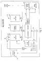
- a data communication system for packet-sourced data preferably mixed with isochronous-sourced data
- the number of nodes can be adjusted depending on the data transmission needs and objectives of the system.
- each hub is configured to accommodate connection with up to 16 nodes.
- Each node 42a, 42b, 42c includes circuitry 50a, 50b, 50c for receiving data, converting it to a form suitable for transmission onto the physical media 46a, 46c, 46e and receipt of signals from the physical media 46b, 46d, 46f and conversion to a form suitable for use by the data sinks.
- Each of the nodes 42a, 42b, 42c includes data sources and sinks 48a-48g.
- the data sources and sinks can be isochronous sources and sinks such as video cameras 48a, 48d and monitors 48b, 48e, packet sources and sinks such as an ethernet media access controller 48c, 48g, and control signaling or D channel sources and sinks such as an emulated or virtual key pad 48f provided, for example, on a personal computer (PC) terminal.
- Each of the nodes 42a, 42b, 42c can include various types of sources and sinks, e.g., strictly isochronous sources and sinks, such as depicted for node 42a, strictly packet-based sources/sinks as depicted for node 42c or both isochronous and packet sources and sinks as depicted for node 42b.
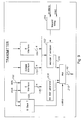
- the physical layer 52 of the network system depicted in Fig. 2 includes the node data receivers and converters 50a, 50b, 50c, the physical media 46a-46f and the hub 44a.
- the hub 44a includes circuitry 54a, 54b, 54c for receiving data from the physical media 46a, 46c, 46e separating the isochronous-sourced data from the packet-sourced data, the D channel and M channel data and converting separated data into a form suitable for handling by downstream hub circuitry 56.
- the separated isochronous-sourced data is provided to a time slot interchange controller for placing the data on a high-bandwidth bus so that it can be transported to and retrieved by hub circuitry 54a, 54b, 54c for transmission to various destination nodes 42a, 42b, 42c.
- the separated packet-sourced data is provided to circuitry 60 configured to convey the non-isochronous data to the hub circuitry 54a, 54b, 54c for transmission to destination nodes 42a, 42b, 42c.
- the hub circuitry 60 can be a standard ethernet repeater processor. In this way, a system which incorporates the present invention can be at least partially backwards-compatible with previous ethernet hub systems.
- the D channel and M channel data is provided to a signaling processor 62 which performs various maintenance and control functions such as identifying and alerting users of error conditions, and setting up requested connections, i.e. source/destination paths e.g. by communicating with the isochronous and non-isochronous controllers 58, 60, e.g. over data path 64.
- Data sent from isochronous device, e.g., 48d is a continuous stream of digitized data from e.g. a video camera.
- the data from isochronous device 48d will be taken as having a data rate equal to the American "T1" standard of 1.544Mb/s.
- Data output from the ethernet MAC 48c is provided at the standard 10BASE-T ethernet rate of 10Mb/sec.
- D channel information is provided from a D channel data stream source, preferably contained in a MAC or other circuitry in the system or, for example, from the virtual keypad 48f at a variable data rate, such as a rate not exceeding about 64Kb/sec.
- incoming data streams are provided over lines 66a, 66b, 66c to node circuitry 50b (Fig. 4).
- the incoming data from the various sources is provided to a multiplexer 70 which performs time-division multiplexing on a four-bit basis.
- the pattern for the time-division multiplexing is a repeating series of frames or templates. In this embodiment of the invention, the frames are repeated every 125 microseconds.
- the initial portion of the frame includes a number of preamble bytes 462a, 462b.
- the frame also includes destination address information 464a,464b, source information 466a,466b, and data fields 468a, 468b.
- the data field could be between 46 and 1500 bytes in length (468a) or between 0 and n bytes (468b).
- Additional frame fields which may be provided, depending on the ethernet system implementation include type fields 470, starting delimiters 472, length fields 474, and frame check sequence fields 476a, 476b.
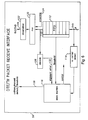
- a media access controller would not output any carrier for an amount of time then (depending on the particular collision avoidance system implemented for the ethernet system) would output a frame such as those depicted in Figs. 10A and 10B which would be accompanied by the presence of a carrier signal on the medium.
- circuitry 412 is connected to the output 414 from the media access controller 48 c which detects the presence or absence of a carrier.
- the frame structure for transmitting the packet-sourced data is a continuously repeating frame structure so that there will always be a carrier signal on the physical medium 46 while the system is in operation. Since the presence or absence of a carrier, is important to the destination (i.e., both the hub repeater 60 and the ultimate node destination 48c) the carrier/no-carrier information should be preserved. In the embodiment depicted in Fig. 7A, this is achieved by instructing a decoder/encoder 416 to output a bit group which is reserved for indicating the absence of a carrier. This "no-carrier" bit group will be inserted in the time slots reserved for the packet-sourced data until such time as a packet is output from the media access controller.
- the packet of data is input to a first-in-first-out (“FIFO") memory 418.
- the FIFO 418 is needed for re-timing the data.
- a packet output by the media access controller will contain a member of 8-bit bytes of data, e.g., between 72 and 1526 bytes per frame. These will be output by the MAC at a predetermined data rate. For example, during transmission of a given frame of ethernet data, one byte will be transmitted every 800 nanoseconds. However, this data rate, on a small time frame, is different from the rate at which the packet data will be placed on the physical medium 46. The data is output on physical medium 46 in 125 microsecond frames, each frame having 256 bytes.
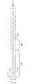
- a 4 bit nibble is output every 0.2441 sec, 450. However, not every time slot is used for packet-sourced data. Referring to Table I, and Fig. 11 after the output of the first 4 bits of ethernet data 452, there will be a wait of 0.2441 sec (during which, isochronous data 454 will be output). This pattern will be repeated six times 456, after which, there will be a transmission of five nibbles of ethernet data contiguously 458. Thereafter, there will be another wait of 0.2441 sec 460 and so forth.
- a given ethernet packet of data will be output from the MAC at a substantially continuous rate (during the packet transmission) of one byte every 800 nanoseconds.
- the data will be placed onto the medium 46 in a discontinuous "lumpy" fashion with several contiguous time slots devoted to transmission of packet-data, but with other packet-data nibbles requiring delays between transmission.
- the FIFO 418 is provided to accommodate this pattern so that the packet data can be input in a continuous fashion (during a packet output from the MAC) and output from the FIFO, as needed, in a discontinuous nibble-wise fashion.
- One of the costs of using a FIFO is the introduction of latency, which is preferably reduced or minimized.
- Certain parameters of the network system are based on the apparent size of the system, i.e., the size that the system appears to have, based on the amount of delay or latency observed.
- An increase in latency in this system increases the apparent size of the system without providing any actual increase in size.
- increase in latency of this system effectively decreases the maximum length the physical wires can have.
- the increased latency introduced by the FIFO can be particularly undesirable since it increases the apparent size of the network, therefore limiting the maximum physical size of the network.
- the FIFO 418 is configured so that it must be filled to a predetermined threshold before any data is output. For example, if the FIFO 418 holds 10 4-bit nibbles of data, in one embodiment the FIFO must contain at least 5 nibbles of data before output can commence. Because of the threshold requirement for the FIFO 418, there is a certain latency, i.e., there is a delay between the time the data is initially input into the FIFO and the time when the threshold is reached, to permit output from the FIFO. According to one embodiment, the delay from the FIFO is reduced by partially filling the FIFO with preamble symbols.
- the preamble generator 420 fills the FIFO 418 half-full of preamble bytes. This immediately meets the threshold requirement of the FIFO so that output can begin, reducing the latency of the FIFO. This reduction in latency is achieved at the cost of increasing the length of the preamble.
- Another latency introduced by the FIFO is a propagation latency, i.e., even in the absence of a threshold latency, there is a certain amount of time required between the time a bit of data is input into the FIFO and the time it has propagated into the point where it can be output from the FIFO.
- the presence of a preamble byte is detected before or as the frame enters the FIFO.
- Circuitry 422 is added to by-pass some of the propagation of ordinary data through the FIFO, to propagate the preamble through the FIFO with a latency shorter than the propagation latency of normal data.
- Timing circuitry 426 controls the rate at which nibbles are output from 418. The timing is configured as to convey data to the transmitter 78 at the proper time slots in accordance with a predetermined template, such as that shown in Table I. Timing circuitry 426 also controls the flow of isochronous data through the decoder/encoder 416, preferably by controlling the output buffer 428 which receives data from isochronous source 48d.
- Table I depicts the manner in which the various data streams, and additional data and control bytes are time-division multiplexed.
- Each symbol in Table I represents four bits of data so that every group of two symbols represents one 8-bit byte of data.
- E represents four bits of data from the ethernet stream 16b
- B designates four bits of data from the isochronous stream 66a
- D represents four bits of data from the control signaling or D channel stream 66c
- M represents four bits of maintenance data as described below.
- certain byte-length patterns are provided.
- JK represents a frame synchronization pattern
- EM the first two bytes of block three in Table I
- each frame contains 256 bytes which can be considered in thirty-two groups of eight bytes each, or four blocks of sixty-four bytes each.
- the frame structure is described more thoroughly in EP-A-0 596 652.
- the described frame structure and frame transmission rate provides data rates for the isochronous and non-isochronous data which are compatible with, e.g., 10BASE-T ethernet data rates.
- the placement of different channels was chosen to minimize the amount of fifoing needed by the packet and isochronous data streams to provide a continuous flow of data.
- Other types of frame structures could be used in connection with other isochronous and/or non-isochronous data sources and sinks such as other types of packet-based systems, or token ring sources and sinks, in which case a different frame structure or template can be used to provide an allocation of bandwidth suited for the particular purpose.
- the frame has one or more time slots which can be used for adjusting the data rate to the particular data rate requirements of various data sources and sinks.
- one or more time slots can be designated as rate-adjustment slots.
- the rate adjustment slots can be used to carry the specified type of data during some time frames but do not carry that specified type of data during other time frames.
- the first symbol of Block 3 can be designated as an ethernet "pad”. By alternating this time slot so that it is used to carry ethernet data during even-numbered time frames and to carry a "no data" symbol during odd-numbered time slots, a data rate adjustment which is, on average, equal to one half of the bandwidth represented by a single time slot can be achieved.
- the transmitter will have its own clock which is preferably used to transmit frames at times determined by a reference clock.
- the frame length can be adjusted to accommodate differences (usually, small differences) in clock rates between the transmit clock and the reference clock. This causes loss of a packet slot which is re-inserted in the next available "pad” time slot.
- the time-multiplexed data is then encoded by a decoder/encoder.
- the purpose of the decoder/encoder 416 is to place the nibble/wise data received from the FIFO 418 and the buffer 428 into a 4/5 encoded form.
- the five bit code symbols of the particular four/five implementation have been chosen so as to maintain the AC balance of the physical medium, and to minimize the frequency spectrum of wave forms as they are transmitted along the physical medium. This eases the task of the data decoder, which is typically a phase lock loop device, in recovering the data and the transmission clock.
- the circuitry 416 and encodes four bits of data from the MAC 48c using the four/five encoding scheme. Circuitry 416 will also encode the data received from the buffer 428.
- the results of the four/five encoding is then further encoded by encoder 74 (Fig. 4) using a non-return to zero, inverted (NRZI) scheme.
- the NRZI encoder modifies the bit stream by inverting the state of the output whenever a logic 1 is to be transmitted. Logic 0 produces no change in output state.
- Four/five-NRZI encoding is particularly useful in networks in which the packet data source is a 10BASE-T ethernet source. This is because the four/five-NRZI encoding allows for transmission at a signaling rate such that the data rate for the packet-sourced portion of the data is substantially compatible with the data rates provided and expected by the ethernet MAC.
- a data rate of 10Mb/sec is provided.
- the data provided at this rate is encoded using two transition times to transfer one bit of data. On average, this scheme provides one clock bit per every bit of data.
- the standard ethernet data rate of 10Mbit/sec after manchester encoding, results in a signalling rate of 20Mbit/sec.
- a frame of data contains 313 "E" symbols or 1252 E bits.
- the present scheme has a capacity for transmitting 10.016Mbits/sec of ethernet-sourced data interspersed with 6144 Kbits/sec of isochronous data.
- the data rate and signaling rate is within two and one-half percent of the signaling and data rate used by 10BASE-T, allowing both isochronous traffic and ethernet traffic to travel over existing physical media 46 without seriously degrading the data rate of the ethernet traffic, compared to previous standard ethernet systems.
- provision of substantially standard ethernet data rates contributes to the ability to implement the present invention without the necessity for replacing in-place MACs or repeater circuitry.
- the ability to convey data frames substantially at the signaling rate used by previously-available systems, such as standard ethernet contributes to the ability to implement the present invention without the necessity to replace in-place physical media, such as twisted pair media.
- the encoding scheme preferably has sufficient efficiency that the bandwidths of both the incoming non-isochronous data 66b and the incoming isochronous data 66a can be accommodated on the physical media 46 without serious degrading, preferably without any degrading, of bandwidth formerly available for the non-isochronous data.
- the four/five encoding scheme is more efficient than differential manchester encoding scheme, in this regard, since it provides four bits of data for every five potential transitions so that, on average, one clock bit is provided for every four bits of data (as opposed to one clock bit for every data bit in differential manchester encoding).
- the differential manchester encoded data took up substantially the entire bandwidth of the twisted pair media, which has a maximum effective signalling rate of about 20Mb/sec
- the four/five-NRZI encoding permits physical media having the same bandwidth to accommodate the 10Mbit/sec ethernet data stream and a 6144Kbit/sec isochronous stream, as well as a 64Kbit/sec control signaling D channel, a 96Kbit/sec maintenance M channel, and 64Kb/sec for the frame synchronization pattern.
- 80Kb/s 64Kb/s + 16Kb/s
- the four/five-NRZI encoding in particularly useful in connection with an ethernet non-isochronous source, other types of encoding or decoding can also be used in the present systems, including a scheme encoding 8 bits into 10 bits or a scrambling scheme.
- the output from the encoding devices is sent to pre-emphasis circuitry 76.
- the pre-emphasis circuitry compensates the signal transmitted onto the physical medium to reduce the jitter.
- the pre-emphasis stage is optimized for the frequency spectrum employed by the present system.
- the data output by the pre-emphasis circuitry 76 is sent to a transmitter or driver 78a and the signal is transmitted over the physical medium 46.
- the physical medium 46 can be any of a number of media types including twisted pair, coaxial or fiber optic cable.
- the data sent over the physical media 46a is received in the hub 44.
- the hub contains a plurality of circuit devices 54a, 54b, 54c, each one coupled to one of the nodes 42a, 42b, 42c by the physical media 46.
- the data transmitted over the physical media 46 arrives serially at a de-serializer/decoder 80.
- Link detect circuitry 82 (Fig. 5) also receives the data from the physical media 46 for detection of the mode in which the node is operating (e.g. 10BASE-T or isochronous ethernet) and outputting a mode select signal, as described more fully in EP-A-0 596 648.
- the de-serializer/decoder includes circuitry which is functionally an inverse of the multiplexing/encoding circuitry described above.
- the de-serializer/decoder includes phase lock decode circuitry 86, the results of which are provided to NRZI decode circuitry 88 which, in turn, provides the decode results to four/five decode circuitry 90, in turn providing results to a de-multiplexer 92 which separates the received data into the isochronous-sourced data 94a the packet-sourced data 94b.
- Signaling data such as D channel 94c and maintenance data 94d, if present, can also be separated at this point.
- Both the packet-sourced data 94b and the isochronous-sourced data 94a are made available to the various hub circuitry components 54a, 54b, 54c, as needed for transmission back to destination nodes or to connected hubs.
- the separated isochronous data 94a and packet-sourced data 94b are reconfigured by the respective interfaces 58, 60 to provide isochronous output 102 and packetized output 104 in a form suitable for processing so as to provide the data as needed for transmission to the destination nodes.
- Fig. 7B depicts only a single incoming twisted pair and a single outgoing twisted pair, there typically will be many sets of twisted pairs, each connected to a different node.
- Each set of outgoing twisted pairs will be connected to its own transmitter, decoder/encoder and E transmit interface.
- data 102 from the non-packet circuitry 58 and data 166 from the repeater 60 are first conveyed to the proper set of output circuitry 54, i.e., the output circuitry which is connected to the destination node for that data.
- the packet-sourced data 94b is configured by the E interface so that the output data 104 can be processed by a repeater device 60 for provision to hub circuitry 54 and eventual transmission to destination nodes.
- packet connections may be linked through media access control layer bridges.
- the output data 104 is in a form such that it can be handled by repeater circuitry of types previously available.
- the packet-sourced data 94b is data which originated at the node 42b from an ethernet MAC 48c and the output data 104 is in a form such that it can be handled by a standard ethernet hub repeater 60 such as a DP83950 "Repeater Interface Controller” (RIC) available from National Semiconductor Corporation, Santa Clara, California.
- a standard ethernet hub repeater 60 such as a DP83950 "Repeater Interface Controller” (RIC) available from National Semiconductor Corporation, Santa Clara, California.
- RIC Remote Interface Controller
- Circuitry 59 can be used to re-time the date in a form appropriate for the repeater 60. Re-timing is necessary, at least for packet-sourced data, for reasons similar to that discussed above in connection with the necessity for the FIFO 418.
- the data received from the media 46 is provided in a discontinuous "lumpy" fashion. This "lumpy" data form is not acceptable for sending to repeater 60 which is configured to receive packets of data similar to the packets output by media access controller 48c. Accordingly, circuitry 59 re-times the discontinuous data to place them to a packet form.
- Circuitry 59 includes a FIFO 432. Circuitry can be provided to reduce the propagation latency of a FIFO, for example, by detecting the input of preamble 422 and propagating the preamble with a latency less than the normal latency of the FIFO for ordinary data.
- repeater circuitry 60 is not of a type previously available, it would be possible to construct a repeater which can handle "lumpy" data arrival rates, and thus the need for buffering the packet data at the hub could be reduced or eliminated.
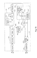
- Fig. 6 depicts one implementation of an E interface 59 of a type which will receive the non-isochronous data 94b and provide outputs 106, 108 of a type that can be processed by previously-available repeater circuitry 60.
- the non-isochronous data is received in a first-in-first-out (FIFO) buffer 432 to smooth out data rates.
- Circuitry 114 detects "no carrier" symbols, provided to emulate ethernet data packets, which will be used by logic circuitry or state machine 116 to output carrier detect signals.
- the output 118 from the FIFO 112 is provided to a multiplexer 120 and a de-serializer 122 to produce data output 106.
- the multiplexer 120 can receive a preamble stream 124 from a preamble generator 125 to provide the proper preamble bits in the output data 106 in a fashion similar to that discussed or the preamble generator 420.
- Output from the FIFO 432 is also provided to decode circuitry 128 to recognize alignment error symbols and output appropriate signals 132 to state machine 116.
- Circuitry 58 can also be provided with a local loop-back capability, as described in EP-A-0 596 452.
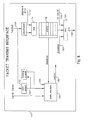
- data 166 output by an ethernet repeater 60 is transformed by an E transmit-interface 168 into a form suitable for supply to the encoder and transmitter.
- An example of an E transmit interface 168 is depicted in Fig. 8.
- the transmit interface depicted in Fig. 8 is, in general, the functional inverse of the E receive interface 60 depicted in Fig. 6.
- the data 166 can be provided in serial form or parallel form.
- the data 166 is de-serialized and is then combined with any necessary alignment error bits 172 (from carrier and frame align detect circuitry 173) in a multiplexer 174, the output of which is conveyed to a FIFO 176.
- the FIFO 176 can be provided with circuitry for reducing latency such as a preamble generator 420'
- a sync detect circuit 178 extracts synchronization information from the repeater output 166 for conveying to a state machine 180.
- the state machine 180 also receives carrier detect information 184, framing counter information 186, and provides control signals 188 to the FIFO 176.
- Data is extracted from the FIFO 176 as needed to make up a frame for transmission over the media 46 as described below.
- the data output from the FIFO 176 is multiplexed with preamble bits 190 and "no carrier" bits 194 by a multiplexer 196.
- the data 198 output from the E transmit interface 168 is provided along with isochronous data output 164 and maintenance and D channel data 172 to encoder serializer circuitry 202, as depicted in Fig. 9.
- the encoder/serializer 202 is configured substantially like the encoding circuitry found in the node and depicted in Fig. 4. Specifically, the encoder/serializer 202 provides a multiplexer for combining the three streams of data 198, 170, 164, a four/five encoder, an NRZI encoder, and pre-emphasis circuitry. The timing of transmission is controlled by transmit timing circuitry 204.
- the data sent from the hub 44a to the nodes 42 is sent in a frame format which is preferably substantially the same as the frame format used for the data sent from the nodes 48 to the hub 44a as described above.
- the circuitry 50 includes devices (Fig. 4) for decoding and de-multiplexing data, similar to that described for performing these functions in the hub, mainly a phase lock decode 86, and NRZI decode 88, a four/five decode 90, and a de-multiplexer 92. Decoded and de-multiplexed data is then delivered to the various data sinks in the nodes 42.
- a buffer circuit 440 substantially similar to buffer circuits 424, 59, 158 receives the separated packet-sourced data and re-times it to convert the "lumpy" discontinuous data defined by the frame structure to a packet form similar to the packet form output by the media access controller 48c.
- the present invention receives packetized data and transmits it over a physical medium in a frame format.
- the frame format permits both packet-sourced data and non-packet-sourced data to be transmitted during each time frame. Both packet-sourced data and non-packet-source data can have dedicated bandwidths available for transmission. The bandwidth available for the packet-sourced data is large enough to achieve a data rate similar to that obtained in previous packetized networks by using an efficient 4/5 encoding scheme.
- the 4/5 encoding scheme contains symbols in addition to those which are available for transmitting information from prior devices for handling for packet data, including "no carrier" information and frame alignment information.
- a FIFO is used to re-time the packet-sourced data for use in the frame structure. Latencies of the FIFOs are reduced by pre-filling all or a portion of the FIFO with packet preamble symbols. In one embodiment, the media access controller does not output preamble symbols and preamble symbols are generated in the buffer circuitry.
- the present invention could be used for transmitting only packet-sourced data without the need for connection to isochronous or other packet sources or sinks. Packet-based data other than Ethernet data can be accommodated by the present invention with appropriate changes to the frame template, including token ring or token bus.
- the network circuitry can be provided in a form which is compatible with previous media access controllers and/or previous hub repeater circuitry, is also possible to provide the present invention in a form where it is not necessary to assure compatibility with previously available media access controllers or hub repeater circuitry.
- the encoder/decoder/NRZI circuitry can be placed either before or after the buffer circuitry.
Description
| BLOCK 0: | ||||||||||||||||
| J | K | E | B | E | B | E | B | E | B | E | B | E | B | E | E | Group0 |
| E | E | E | B | E | B | E | B | E | B | E | B | E | B | E | E | Group1 |
| E | E | E | B | E | B | E | B | E | B | E | B | E | B | E | E | Group2 |
| E | E | E | B | E | B | E | B | E | B | E | B | E | B | E | E | Group3 |
| E | E | E | B | E | B | E | B | E | B | E | B | E | B | E | E | Group4 |
| E | E | E | B | E | B | E | B | E | B | E | B | E | B | E | E | Group5 |
| E | E | E | B | E | B | E | B | E | B | E | B | E | B | E | E | Group6 |
| E | E | E | B | E | B | E | B | E | B | E | B | E | B | E | E | Group7 |
| BLOCK 1: | ||||||||||||||||
| M | M | E | B | E | B | E | B | E | B | E | B | E | B | E | E | Group8 |
| E | E | E | B | E | B | E | B | E | B | E | B | E | B | E | E | Group9 |
| E | E | E | B | E | B | E | B | E | B | E | B | E | B | E | E | Group10 |
| E | E | E | B | E | B | E | B | E | B | E | B | E | B | E | E | Group11 |
| E | E | E | B | E | B | E | B | E | B | E | B | E | B | E | E | Group12 |
| E | E | E | B | E | B | E | B | E | B | E | B | E | B | E | E | Group13 |
| E | E | E | B | E | B | E | B | E | B | E | B | E | B | E | E | Group14 |
| E | E | E | B | E | B | E | B | E | B | E | B | E | B | E | E | Group15 |
| BLOCK 2: | ||||||||||||||||
| D | D | E | B | E | B | E | B | E | B | E | B | E | B | E | E | Group16 |
| E | E | E | B | E | B | E | B | E | B | E | B | E | B | E | E | Group17 |
| E | E | E | B | E | B | E | B | E | B | E | B | E | B | E | E | Group18 |
| E | E | E | B | E | B | E | B | E | B | E | B | E | B | E | E | Group19 |
| E | E | E | B | E | B | E | B | E | B | E | B | E | B | E | E | Group20 |
| E | E | E | B | E | B | E | B | E | B | E | B | E | B | E | E | Group21 |
| E | E | E | B | E | B | E | B | E | B | E | B | E | B | E | E | Group22 |
| E | E | E | B | E | B | E | B | E | B | E | B | E | B | E | E | Group23 |
| BLOCK 3: | ||||||||||||||||
| E | M | E | B | E | B | E | B | E | B | E | B | E | B | E | E | Group24 |
| E | E | E | B | E | B | E | B | E | B | E | B | E | B | E | E | Group25 |
| E | E | E | B | E | B | E | B | E | B | E | B | E | B | E | E | Group26 |
| E | E | E | B | E | B | E | B | E | B | E | B | E | B | E | E | Group27 |
| E | E | E | B | E | B | E | B | E | B | E | B | E | B | E | E | Group28 |
| E | E | E | B | E | B | E | B | E | B | E | B | E | B | E | E | Group29 |
| E | E | E | B | E | B | E | B | E | B | E | B | E | B | E | E | Group30 |
| E | E | E | B | E | B | E | B | E | B | E | B | E | B | E | E | Group31 |
| JK = Frame Synchronization Pattern | ||||||||||||||||
| MM = 8 Maintenance Bits | ||||||||||||||||
| D = D Channel | ||||||||||||||||
| EM = Ethernet Pad & 4 Maintenance Bits | ||||||||||||||||
| E = Ethernet Packet Channel | ||||||||||||||||
| B = Isochronous Channel |
| Symbol | Encoded (5 bit) | Decoded (4 bit) | |
| 0 | 11110 | 0000 | |
| 1 | 01001 | 0001 | |
| 2 | 10100 | 0010 | |
| 3 | 10101 | 0011 | |
| 4 | 01010 | 0100 | |
| 5 | 01011 | 0101 | Data 5 |
| 6 | 01110 | 0110 | |
| 7 | 01111 | 0111 | |
| 8 | 10010 | 1000 | |
| 9 | 10011 | 1001 | Data 9 |
| A | 10110 | 1010 | Data A |
| B | 10111 | 1011 | Data B |
| C | 11010 | 1100 | Data C |
| D | 11011 | 1101 | Data D |
| E | 11100 | 1110 | Data E |
| F | 11101 | 1111 | Data F |
| I | 11111 | 1010 | No Ethernet Carrier |
| S | 11001 | 0111 | No Ethernet Data |
| V | 01100 | 0010 | Unaligned Data |
| T | 01101 | 0101 | Unassigned |
| J | 11000 | 1101 | Frame Sync Part 1 |
| K | 10001 | 1101 | Frame Sync Part 2 |
| Q | 00000 | 0010 | Invalid |
| H | 00100 | 0001 | Invalid |
| R | 00111 | 0110 | Invalid |
| V | 00001 | 0110 | Invalid |
| V | 00010 | 0010 | Invalid |
| V | 00011 | 0010 | Invalid |
| V | 00101 | 0010 | Invalid |
| V | 00110 | 0010 | Invalid |
| V | 01000 | 0010 | Invalid |
| V | 10000 | 0010 | Invalid |
| Channel | Bytes/Frame | Bits/Frame | Kbits/sec | Usage |
| JK | 1.0 | 8 | 64 | Frame Synchronization |
| B | 96.0 | 768 | 6,144 | Isochronous |
| E | 156.5 | 1,252 | 10,016 | Ethernet Packet |
| D | 1.0 | 8 | 64 | D channel |
| M | 1.5 | 12 | 96 | Maintenance |
| 256.0 | 2,048 | 16.384 | Mbits/sec |
Claims (27)
- Apparatus for conveying data from a data source, over physical media, to a data sink, said data source including a media access controller which is adapted to output first data in a packet form, the apparatus comprising:a first buffer (424), coupled to said media access controller (48c) for receiving said first data in packet form and outputting at least said first data as a first plurality of groups of bits of said first data;a transmitter (78) coupled to said first buffer for receiving said first plurality of groups of bits of said first data and coupled to said physical media for transmitting said first plurality of groups of bits of said first data onto said physical media,a reference clock, coupled to said transmitter, for establishing the beginning times of a plurality of contiguous time frames, each time frame having a plurality of time slots, wherein each of said first plurality of groups of bits is transmitted by said transmitter during a first set of predetermined ones of said time slots, at least some of said first set of predetermined ones of said time slots being non-contiguous.
- Apparatus, as claimed in claim 1, further comprising:an isochronous data source (48d) outputting isochronous data;said transmitter being coupled to said isochronous data source for receiving a second plurality of groups of bits of said isochronous data wherein each of said second plurality of groups of bits is transmitted by said transmitter onto said physical media during a second set of predetermined ones of said time slots, said second set being different from said first set.
- Apparatus, as claimed in claim 1, wherein said media access controller (48c) is an ethernet media access controller.
- Apparatus, as claimed in claim 1, further comprising an encoder (416) for receiving at least said first data and outputting encoded data in a first encoded form according to a 4/5 encoding scheme wherein 4 bits of data are encoded into a 5-bit group.
- Apparatus, as claimed in claim 4, further comprising a deserializer for receiving serial data and providing data, four bits at a time, to said encoder.
- Apparatus, as claimed in claim 4, wherein said deserializer receives said first data from said media access controller and said encoder outputs said encoded data to said first buffer.
- Apparatus, as claimed in claim 4, wherein said deserializer receives said first data from said first buffer and said encoder outputs said encoded data to said transmitter.
- Apparatus, as claimed in claim 4, wherein said encoder includes an NRZI encoder.
- Apparatus, as claimed in claim 4, wherein said data sink includes a repeater (60) for said first data, configured to receive said first data in a second encoded form and further comprising:an encoder in said data sink for placing said data in said second encoded form.
- Apparatus, as claimed in claim 9, wherein said second encoded form is differential manchester encoding.
- Apparatus, as claimed in claim 1, wherein each of said first plurality of groups of data bits includes the same number of bits.
- Apparatus, as claimed in claim 11, wherein said number of bits is 4.
- Apparatus, as claimed in claim 1, wherein said transmitter transmits said first data at a first effective bandwidth of about 10Mb/sec.
- Apparatus, as claimed in claim 2, wherein said transmitter transmits said isochronous data at a second effective bandwidth of about 6.144Mb/sec.
- Apparatus, as claimed in claim 1, wherein said first buffer (424) comprises a first-in-first-out memory (418).
- Apparatus, as claimed in claim 1, wherein:
said encoder output includes a third plurality of bit groups and at least a fourth bit group different from the bit groups in said third plurality of bit groups. - Apparatus, as claimed in claim 16, whereinsaid media access controller (48c) is adapted to output a carrier signal during at least a first time period, to not output said carrier signal during at least a second time period which occurs after said first time period and to output said carrier signal during a third time period which occurs after said second time period, and whereinsaid encoder (416) is adapted to output one or more bit groups from said third plurality of bit groups in response to receipt of the media access controller output which occurs during said first time period, to output at least said fourth bit group in response to receipt of the media access controller output which occurs during said second time period and to output one or more bit groups from said third plurality of bit groups in response to receipt of the media access controller output which occurs during said third time period.
- Apparatus, as claimed in claim 1, wherein said media access controller (48c) which is adapted to output said first data in a packet form is adapted to output a first indication of the beginning of a packet, to output a first number of data bits after said output of said first indication and outputs an indication of the end of a packet, after said output of said first number of data bits and further comprising:circuitry for determining whether said first number of data bits is divisible evenly by a predetermined integer and for outputting a frame alignment signal if said first number of data bits is not divisible evenly by said predetermined integer.
- Apparatus, as claimed in claim 18, wherein said predetermined integer is 4.
- Apparatus, as claimed in claim 18, wherein said frame alignment signal is transmitted during one of said first set of said predetermined ones of said time slots.
- Apparatus, as claimed in claim 1, wherein said data sink includes a repeater (60) for said first data, configured to receive said first data at a first data rate and further comprising:a buffer in said data sink for receiving said first data from said physical media, and outputting said first data at said first data rate to said repeater.
- Apparatus, as claimed in claim 1 wherein said media access controller (48c) is adapted to output a preamble comprising at least one preamble symbol prior to outputting at least said first data and, and wherein said first buffer is adapted to require at least a first latency period between initial receipt of said first data and beginning output of said first data; andsaid first buffer (424) includes circuitry for distinguishing said preamble symbol from said first data and for outputting said preamble symbol a second period after receipt of said preamble symbol, said second period being less than said first latency period.
- Apparatus, as claimed in claim 1 wherein said media access controller (48c) is adapted to output a preamble comprising at least one preamble symbol prior to outputting at least said first data and, and wherein said buffer is adapted to require at least a first length of data to be input before beginning output of said data; andsaid buffer (424) includes circuitry for extending said preamble by repeating the output of said preamble symbol at least until said first length of said first data has been input into said buffer.
- Apparatus, as claimed in claim 1 wherein said media access controller (48c) is adapted so as not to output a preamble prior to outputting said first data; andsaid buffer includes circuitry for generating and outputting at least one preamble symbol prior to outputting said first data.
- Apparatus, as claimed in claim 1, wherein said data sink is a hub of a star-topology network and said data source is a node of said star-topology network.
- A method for transmitting both data from a packet source and data from an isochronous source onto a physical medium comprising:transmitting signals onto said physical medium during a first time frame, said frame comprising a predetermined number of time slots, according to a first template whereinrepeating said step of transmitting, during subsequent time frames, at regular time intervals, according to said first template.a first plurality of said time slots (454) is used for transmission of a first plurality of symbols in response to said isochronous data source, each of said first plurality of symbols comprising a plurality of bit-groups, each for conveying a first predetermined number of data bits, anda second plurality of said time slots (452) is used for transmission of a second plurality of symbols in response to said packet source, said second plurality of symbols comprising at least a first bit-group for transmission in response to a period of non-output of a packet from said packet source and a plurality of bit-groups, different from said first bit-group, each for conveying a first predetermined number of data bits in response to output of a packet from said packet source; and
- Apparatus for transmitting both data from a packet source and data from an isochronous source onto a physical medium comprising:means for transmitting signals onto said physical medium during a first time frame, said frame comprising a predetermined number of time slots, according to a first template whereina first plurality of said time slots (454) is used for transmission of a first plurality of symbols in response to said isochronous data source, each of said first plurality of symbols comprising a plurality of bit-groups, each for conveying a first predetermined number of data bits, anda second plurality of said time slots (452) is used for transmission of a second plurality of symbols in response to said packet source, said second plurality of symbols comprising at least a first bit-group for transmission in response to a period of non-output of a packet from said packet source and a plurality of bit-groups, different from said first bit-group, each for conveying a first predetermined number of data bits in response to output of a packet from said packet source; andmeans for repeating said step of transmitting, during subsequent time frames, at regular time intervals, according to said first template.
Applications Claiming Priority (2)
| Application Number | Priority Date | Filing Date | Title |
|---|---|---|---|
| US07/970,329 US5361261A (en) | 1992-11-02 | 1992-11-02 | Frame-based transmission of data |
| US970329 | 1992-11-02 |
Publications (2)
| Publication Number | Publication Date |
|---|---|
| EP0596645A1 EP0596645A1 (en) | 1994-05-11 |
| EP0596645B1 true EP0596645B1 (en) | 1998-08-05 |
Family
ID=25516777
Family Applications (1)
| Application Number | Title | Priority Date | Filing Date |
|---|---|---|---|
| EP93308555A Expired - Lifetime EP0596645B1 (en) | 1992-11-02 | 1993-10-27 | Frame-based transmission of data |
Country Status (5)
| Country | Link |
|---|---|
| US (1) | US5361261A (en) |
| EP (1) | EP0596645B1 (en) |
| JP (1) | JP3448086B2 (en) |
| KR (1) | KR100283462B1 (en) |
| DE (1) | DE69320143T2 (en) |
Cited By (1)
| Publication number | Priority date | Publication date | Assignee | Title |
|---|---|---|---|---|
| US8800059B2 (en) | 1999-03-19 | 2014-08-05 | Broadcom Corporation | System and method for processing and protecting content |
Families Citing this family (121)
| Publication number | Priority date | Publication date | Assignee | Title |
|---|---|---|---|---|
| EP0596651A1 (en) | 1992-11-02 | 1994-05-11 | National Semiconductor Corporation | Network for data communication with isochronous capability |
| EP0596648A1 (en) | 1992-11-02 | 1994-05-11 | National Semiconductor Corporation | Network link endpoint capability detection |
| USRE39116E1 (en) | 1992-11-02 | 2006-06-06 | Negotiated Data Solutions Llc | Network link detection and generation |
| US5548790A (en) * | 1993-02-10 | 1996-08-20 | Capital Equipment Corporation | High speed IEEE 488 bus data transfer system |
| US5550982A (en) * | 1993-06-24 | 1996-08-27 | Starlight Networks | Video application server |
| US5625624A (en) * | 1993-10-21 | 1997-04-29 | Hughes Aircraft Company | High data rate satellite communication system |
| CA2118278C (en) * | 1993-12-21 | 1999-09-07 | J. David Garland | Multimedia system |
| US5577069A (en) * | 1994-08-02 | 1996-11-19 | National Semiconductor Corporation | Signalling method and structure suitable for out-of-band information transfer in communication network |
| US5553071A (en) * | 1994-10-14 | 1996-09-03 | Lucent Technologies Inc. | Communication system topology providing dynamic allocation of B-channels |
| US5742847A (en) * | 1994-10-31 | 1998-04-21 | Intel Corporation | M&A for dynamically generating and maintaining frame based polling schedules for polling isochronous and asynchronous functions that guaranty latencies and bandwidths to the isochronous functions |
| US5615404A (en) * | 1994-10-31 | 1997-03-25 | Intel Corporation | System having independently addressable bus interfaces coupled to serially connected multi-ported signal distributors generating and maintaining frame based polling schedule favoring isochronous peripherals |
| US5623610A (en) * | 1994-10-31 | 1997-04-22 | Intel Corporation | System for assigning geographical addresses in a hierarchical serial bus by enabling upstream port and selectively enabling disabled ports at power on/reset |
| US5621901A (en) * | 1994-10-31 | 1997-04-15 | Intel Corporation | Method and apparatus for serial bus elements of an hierarchical serial bus assembly to electrically represent data and control states to each other |
| GB2308533B (en) * | 1994-10-31 | 1999-04-07 | Intel Corp | M & A for exchanging data, status, and commands over a hierarchical |
| US5533018A (en) * | 1994-12-21 | 1996-07-02 | National Semiconductor Corporation | Multi-protocol packet framing over an isochronous network |
| JP2944440B2 (en) * | 1994-12-27 | 1999-09-06 | 日本電気株式会社 | Time division multiplex transmission equipment |
| WO1996024993A1 (en) * | 1995-02-10 | 1996-08-15 | National Semiconductor Corporation | Method and apparatus for transmitting data isochronously at a rate less than the isochronous data rate |
| US5862343A (en) * | 1995-02-10 | 1999-01-19 | National Semiconductor Corporation | Circuit for logical stream sorting at CPU transfer time division for multiplexed (TDM) including bus interface circuitry |
| US5790786A (en) * | 1995-06-28 | 1998-08-04 | National Semiconductor Corporation | Multi-media-access-controller circuit for a network hub |
| US5822325A (en) * | 1995-07-10 | 1998-10-13 | National Semiconductor Corporation | Integrated twisted pair filter with a secure RIC function |
| US5996018A (en) * | 1995-12-06 | 1999-11-30 | International Business Machines Corporation | Method and apparatus to reduce jitter and end-to-end delay for multimedia data signalling |
| US5790538A (en) * | 1996-01-26 | 1998-08-04 | Telogy Networks, Inc. | System and method for voice Playout in an asynchronous packet network |
| US7577782B2 (en) | 1996-02-02 | 2009-08-18 | Sony Corporation | Application programming interface for data transfer and bus management over a bus structure |
| US6631435B1 (en) | 1996-02-02 | 2003-10-07 | Sony Corporation | Application programming interface for data transfer and bus management over a bus structure |
| US5878221A (en) * | 1996-02-05 | 1999-03-02 | Xinex Networks Inc. | Network for multimedia asynchronous transfer mode digital signal transmission and components thereof |
| US5799041A (en) * | 1996-02-05 | 1998-08-25 | Xinex Networks Inc. | Network for multimedia asynchronous transfer mode digital signal transmission and components thereof |
| US6519268B1 (en) | 1996-03-07 | 2003-02-11 | Sony Corporation | Asynchronous data pipe for automatically managing asynchronous data transfers between an application and a bus structure |
| US6233637B1 (en) | 1996-03-07 | 2001-05-15 | Sony Corporation | Isochronous data pipe for managing and manipulating a high-speed stream of isochronous data flowing between an application and a bus structure |
| US5761430A (en) * | 1996-04-12 | 1998-06-02 | Peak Audio, Inc. | Media access control for isochronous data packets in carrier sensing multiple access systems |
| US6339584B1 (en) | 1996-04-12 | 2002-01-15 | Cirrus Logic, Inc. | Media access control for isochronous data packets in carrier sensing multiple access systems |
| US5805597A (en) * | 1996-06-04 | 1998-09-08 | National Semiconductor Corporation | Method and apparatus for providing low power basic telephony type service over a twisted pair ethernet physical layer |
| CA2232624A1 (en) | 1996-07-19 | 1998-01-29 | Sony Corporation | Transmission apparatus and transmission method for digital data |
| US6122281A (en) * | 1996-07-22 | 2000-09-19 | Cabletron Systems, Inc. | Method and apparatus for transmitting LAN data over a synchronous wide area network |
| DE19642258C1 (en) * | 1996-10-11 | 1998-03-26 | Becker Gmbh | Digital data transmission method e.g. for audio data |
| DE19641930C1 (en) * | 1996-10-11 | 1998-03-05 | Becker Gmbh | Communication system |
| US5901148A (en) * | 1997-03-06 | 1999-05-04 | Lockheed Martin Corporation | Ring domains for bandwidth sharing |
| US5892767A (en) * | 1997-03-11 | 1999-04-06 | Selsius Systems Inc. | Systems and method for multicasting a video stream and communications network employing the same |
| US6115386A (en) * | 1997-03-11 | 2000-09-05 | Cisco Systems, Inc. | Systems and methods for transferring a bonded call |
| CN100385887C (en) * | 1997-05-07 | 2008-04-30 | 西门子公司 | Method and device for coding, transmitting and decoding digital data |
| US5946327A (en) * | 1997-09-09 | 1999-08-31 | 3Com Corporation | Method and apparatus for converting between a multi-bit TDM bus and a single-bit TDM bus using digital logic |
| US6697385B1 (en) * | 1997-09-23 | 2004-02-24 | Cypress Semiconductor Corp. | Circuit(s), method(s) and architecture for configurable packet re-timing in network repeater hubs |
| US6504840B1 (en) * | 1997-09-24 | 2003-01-07 | Net Insight Ab | Method, system and apparatus for transferring information between nodes in a circuit switched time division multiplexed method |
| US7272298B1 (en) | 1998-05-06 | 2007-09-18 | Burst.Com, Inc. | System and method for time-shifted program viewing |
| US6577631B1 (en) | 1998-06-10 | 2003-06-10 | Merlot Communications, Inc. | Communication switching module for the transmission and control of audio, video, and computer data over a single network fabric |
| US6295010B1 (en) * | 1998-07-02 | 2001-09-25 | Seagate Technology, Llc | 8B/10B encoder system and method |
| US6233389B1 (en) | 1998-07-30 | 2001-05-15 | Tivo, Inc. | Multimedia time warping system |
| US8380041B2 (en) | 1998-07-30 | 2013-02-19 | Tivo Inc. | Transportable digital video recorder system |
| US7558472B2 (en) | 2000-08-22 | 2009-07-07 | Tivo Inc. | Multimedia signal processing system |
| US8577205B2 (en) | 1998-07-30 | 2013-11-05 | Tivo Inc. | Digital video recording system |
| US6584118B1 (en) * | 1998-08-27 | 2003-06-24 | Nortel Networks Limited | Payload mapping in synchronous networks |
| US6167471A (en) | 1998-10-14 | 2000-12-26 | Sony Corporation | Method of and apparatus for dispatching a processing element to a program location based on channel number of received data |
| US6760308B1 (en) | 1999-02-26 | 2004-07-06 | Bitbytebit Information Services, Inc. | Adaptive transmission in multi-access asynchronous channels |
| US6868072B1 (en) | 1999-03-19 | 2005-03-15 | Broadcom Corporation | Home phone line network architecture |
| WO2000056928A2 (en) * | 1999-03-19 | 2000-09-28 | Broadcom Corporation | Home phone line network architecture |
| US6247069B1 (en) | 1999-05-12 | 2001-06-12 | Sony Corporation | Automatically configuring storage array including a plurality of media storage devices for storing and providing data within a network of devices |
| US6859846B2 (en) | 1999-05-12 | 2005-02-22 | Sony Corporation | Method of distributed recording whereby the need to transition to a second recording device from a first recording device is broadcast by the first recording device |
| DE19941742A1 (en) * | 1999-09-02 | 2001-03-08 | Vitronic Dr Ing Stein Bildvera | Circuit for generating image data for a PC and corresponding method for data transfer |
| EP1214842B1 (en) | 1999-09-20 | 2010-11-17 | TiVo, Inc. | Closed caption tagging system |
| US6721859B1 (en) | 1999-10-21 | 2004-04-13 | Sony Corporation | Multi-protocol media storage device implementing protocols optimized for storing and retrieving both asynchronous and isochronous data |
| US6523108B1 (en) | 1999-11-23 | 2003-02-18 | Sony Corporation | Method of and apparatus for extracting a string of bits from a binary bit string and depositing a string of bits onto a binary bit string |
| US6574225B2 (en) * | 2000-04-07 | 2003-06-03 | Omneon Video Networks | Clock recovery in a packet-based data network |
| US6813729B1 (en) | 2000-06-15 | 2004-11-02 | Advanced Micro Devices, Inc. | Programmable bi-directional MII testing methodology and device including same |
| US6978318B1 (en) | 2000-06-19 | 2005-12-20 | Advanced Micro Devices, Inc. | Network interface apparatus and method of internal communication within the same |
| US6937571B1 (en) | 2000-06-19 | 2005-08-30 | Advanced Micro Devices, Inc. | Method of testing a network device through a medium independent interface (MII) |
| US7720821B1 (en) | 2000-06-30 | 2010-05-18 | Sony Corporation | Method of and apparatus for writing and reading time sensitive data within a storage device |
| US6975652B1 (en) | 2000-10-18 | 2005-12-13 | 3Com Corporation | Clock synchronization of HFC telephone equipment |
| US6904475B1 (en) | 2000-11-06 | 2005-06-07 | Sony Corporation | Programmable first-in first-out (FIFO) memory buffer for concurrent data stream handling |
| GB2377865B (en) * | 2001-04-07 | 2004-04-28 | Bob Tang | Eliminating latency introduced by IP packet/ATM cell/Ethernet frame (etc..) header in transmitting periodic data over the internet |
| US7124292B2 (en) | 2001-05-21 | 2006-10-17 | Sony Corporation | Automatically configuring storage array including a plurality of media storage devices for storing and providing data within a network of devices |
| DE10149332A1 (en) | 2001-10-06 | 2003-04-30 | Bosch Gmbh Robert | Method for transmitting data from at least one sensor to a control device |
| US6990109B2 (en) * | 2001-10-31 | 2006-01-24 | Adtran, Inc. | Method and apparatus for providing reliable voice and voice-band data transmission over asynchronous transfer mode (ATM) network |
| JP4477877B2 (en) * | 2001-12-03 | 2010-06-09 | エヌエックスピー ビー ヴィ | Communication bus system |
| JP3947424B2 (en) | 2002-05-02 | 2007-07-18 | 株式会社エヌ・ティ・ティ・ドコモ | Packet transmission control device, mobile node, control node, packet communication method, and packet communication system |
| US7499403B2 (en) * | 2003-05-07 | 2009-03-03 | Alcatel-Lucent Usa Inc. | Control component removal of one or more encoded frames from isochronous telecommunication stream based on one or more code rates of the one or more encoded frames to create non-isochronous telecommunications stream |
| US20050117571A1 (en) * | 2003-12-01 | 2005-06-02 | Dyke Robert G. | Distribution of time division multiplexed data through packet connections |
| US7277031B1 (en) | 2003-12-15 | 2007-10-02 | Marvell International Ltd. | 100Base-FX serializer/deserializer using 10000Base-X serializer/deserializer |
| US7379453B1 (en) * | 2004-03-29 | 2008-05-27 | Sun Microsystems, Inc. | Method and apparatus for transferring multiple packets from hardware |
| CN1691666B (en) * | 2004-04-21 | 2010-04-14 | 华为技术有限公司 | Method of multi-protocol universal line transmission and device therefor |
| AU2005306361B2 (en) | 2004-11-19 | 2011-02-10 | Tivo Inc. | Method and apparatus for secure transfer of previously broadcasted content |
| US20060133415A1 (en) * | 2004-12-21 | 2006-06-22 | Mueller Peter D | Wireless internetwork transfer apparatus, systems, and methods |
| US7675945B2 (en) * | 2006-09-25 | 2010-03-09 | Futurewei Technologies, Inc. | Multi-component compatible data architecture |
| US7986700B2 (en) * | 2006-09-25 | 2011-07-26 | Futurewei Technologies, Inc. | Multiplexed data stream circuit architecture |
| US8340101B2 (en) * | 2006-09-25 | 2012-12-25 | Futurewei Technologies, Inc. | Multiplexed data stream payload format |
| US8660152B2 (en) | 2006-09-25 | 2014-02-25 | Futurewei Technologies, Inc. | Multi-frame network clock synchronization |
| US8494009B2 (en) * | 2006-09-25 | 2013-07-23 | Futurewei Technologies, Inc. | Network clock synchronization timestamp |
| US8976796B2 (en) * | 2006-09-25 | 2015-03-10 | Futurewei Technologies, Inc. | Bandwidth reuse in multiplexed data stream |
| US8295310B2 (en) | 2006-09-25 | 2012-10-23 | Futurewei Technologies, Inc. | Inter-packet gap network clock synchronization |
| US7813271B2 (en) * | 2006-09-25 | 2010-10-12 | Futurewei Technologies, Inc. | Aggregated link traffic protection |
| US7809027B2 (en) | 2006-09-25 | 2010-10-05 | Futurewei Technologies, Inc. | Network clock synchronization floating window and window delineation |
| US8588209B2 (en) * | 2006-09-25 | 2013-11-19 | Futurewei Technologies, Inc. | Multi-network compatible data architecture |
| US7961751B2 (en) * | 2006-09-25 | 2011-06-14 | Futurewei Technologies, Inc. | Multiplexed data stream timeslot map |
| CN101578794B (en) * | 2007-01-26 | 2012-12-12 | 华为技术有限公司 | Multiplexed data stream circuit architecture |
| US8085858B2 (en) | 2007-02-07 | 2011-12-27 | Valens Semiconductor Ltd. | Power saving techniques for a partial functionality communication link |
| US9426006B2 (en) * | 2007-02-07 | 2016-08-23 | Valens Semiconductor Ltd. | Low power partial functionality communication link |
| US20080291986A1 (en) * | 2007-02-07 | 2008-11-27 | Valens Semiconductor Ltd. | Low power partial functionality modems |
| US8364991B2 (en) * | 2007-02-07 | 2013-01-29 | Valens Semiconductor Ltd. | Ethernet low power partial functionality communication link |
| US7835382B2 (en) * | 2007-02-07 | 2010-11-16 | Valens Semiconductor Ltd. | High definition and low power partial functionality communication link |
| US8355327B2 (en) * | 2007-02-07 | 2013-01-15 | Valens Semiconductor Ltd. | Methods and devices for daisy chain CE device power save modes |
| US7835289B2 (en) * | 2007-02-07 | 2010-11-16 | Valens Semiconductor Ltd. | Methods for managing a multi data type communication link |
| FR2915338A1 (en) * | 2007-04-17 | 2008-10-24 | Canon Kk | METHOD FOR TRANSMITTING AND RECEIVING DATA CONTENTS IN A COMMUNICATION NETWORK, COMPUTER PROGRAM PRODUCT, STORAGE MEDIUM AND DEVICES THEREOF |
| WO2009003518A1 (en) * | 2007-07-04 | 2009-01-08 | Airbus Operations Gmbh | Deterministic communication system |
| US8136140B2 (en) | 2007-11-20 | 2012-03-13 | Dish Network L.L.C. | Methods and apparatus for generating metadata utilized to filter content from a video stream using text data |
| US8165451B2 (en) | 2007-11-20 | 2012-04-24 | Echostar Technologies L.L.C. | Methods and apparatus for displaying information regarding interstitials of a video stream |
| US8165450B2 (en) | 2007-11-19 | 2012-04-24 | Echostar Technologies L.L.C. | Methods and apparatus for filtering content in a video stream using text data |
| US8606085B2 (en) | 2008-03-20 | 2013-12-10 | Dish Network L.L.C. | Method and apparatus for replacement of audio data in recorded audio/video stream |
| US8156520B2 (en) | 2008-05-30 | 2012-04-10 | EchoStar Technologies, L.L.C. | Methods and apparatus for presenting substitute content in an audio/video stream using text data |
| US20100036805A1 (en) * | 2008-08-05 | 2010-02-11 | International Business Machines Corporation | System Maintainable and Reusable I/O Value Caches |
| US8407735B2 (en) | 2008-12-24 | 2013-03-26 | Echostar Technologies L.L.C. | Methods and apparatus for identifying segments of content in a presentation stream using signature data |
| US8510771B2 (en) | 2008-12-24 | 2013-08-13 | Echostar Technologies L.L.C. | Methods and apparatus for filtering content from a presentation stream using signature data |
| US8588579B2 (en) | 2008-12-24 | 2013-11-19 | Echostar Technologies L.L.C. | Methods and apparatus for filtering and inserting content into a presentation stream using signature data |
| US8437617B2 (en) | 2009-06-17 | 2013-05-07 | Echostar Technologies L.L.C. | Method and apparatus for modifying the presentation of content |
| CN102792741B (en) * | 2009-12-14 | 2015-12-16 | 法国电信 | The method of the transmit communications signals improved |
| US8934758B2 (en) | 2010-02-09 | 2015-01-13 | Echostar Global B.V. | Methods and apparatus for presenting supplemental content in association with recorded content |
| US8555065B2 (en) | 2011-08-24 | 2013-10-08 | Jeffrey Thomas CESNIK | Method and apparatus for transmitting, receiving and decoding data using encoded patterns of changing colors |
| US9787404B2 (en) * | 2013-09-16 | 2017-10-10 | Clutch Authentication Systems, Llc | System and method for communication over color encoded light patterns |
| US20150155937A1 (en) * | 2013-09-16 | 2015-06-04 | Clutch Authentication Systems, Llc | System and method for communication over color encoded light patterns |
| US9548814B2 (en) * | 2013-09-16 | 2017-01-17 | Clutch Authentication Systems, Llc | System and method for communication over color encoded light patterns |
| US20150104184A1 (en) * | 2013-09-16 | 2015-04-16 | Clutch Authentication Systems, Llc | System and method for communication over color encoded light patterns |
| US20150155938A1 (en) * | 2013-09-16 | 2015-06-04 | Clutch Authentication Systems, Llc | System and method for communication over color encoded light patterns |
| WO2020075228A1 (en) | 2018-10-10 | 2020-04-16 | Sumitomo Electric Hardmetal Corp. | Cutting insert and cutting tool |
| US11172269B2 (en) | 2020-03-04 | 2021-11-09 | Dish Network L.L.C. | Automated commercial content shifting in a video streaming system |
Family Cites Families (16)
| Publication number | Priority date | Publication date | Assignee | Title |
|---|---|---|---|---|
| GB1566223A (en) * | 1978-01-17 | 1980-04-30 | Standard Telephones Cables Ltd | Digital duplex transmission system |
| FR2430141A1 (en) * | 1978-06-29 | 1980-01-25 | Glowinski Albert | BIT-TO-BIT DIGITAL TIME-SWITCHING NETWORK |
| FR2483145A2 (en) * | 1980-05-23 | 1981-11-27 | France Etat | IMPROVEMENTS TO DIGITAL SWITCHING NETWORKS WITH TIME DIVISION BIT AT BIT |
| US4530088A (en) * | 1983-02-15 | 1985-07-16 | Sperry Corporation | Group coding system for serial data transmission |
| US4637014A (en) * | 1984-02-17 | 1987-01-13 | Burroughs Corporation | Method of inserting and removing isochronous data into a sequence of nonisochronous data characters without slot allocation on a computer network |
| US4549292A (en) * | 1984-02-17 | 1985-10-22 | Burroughs Corporation | Method of efficiently and simultaneously transmitting both isochronous and nonisochronous data in a computer network |
| US4587650A (en) * | 1984-10-30 | 1986-05-06 | Burroughs Corporation | Method of simultaneously transmitting isochronous and nonisochronous data on a local area network |
| IL79775A (en) * | 1985-08-23 | 1990-06-10 | Republic Telcom Systems Corp | Multiplexed digital packet telephone system |
| US4845609A (en) * | 1986-07-25 | 1989-07-04 | Systech Corporation | Computer communications subsystem using an embedded token-passing network |
| JPH0642663B2 (en) * | 1988-03-16 | 1994-06-01 | 富士通株式会社 | Intermediate relay station of digital communication system |
| JP2845889B2 (en) * | 1988-05-16 | 1999-01-13 | 株式会社日立製作所 | Satellite communication system and satellite communication system |
| US4858232A (en) * | 1988-05-20 | 1989-08-15 | Dsc Communications Corporation | Distributed switching system |
| JPH0813057B2 (en) * | 1989-02-03 | 1996-02-07 | 日本電気株式会社 | Mixed transfer method of HDLC variable length packet and non-HDLC fixed length packet |
| US4961188A (en) * | 1989-09-07 | 1990-10-02 | Bell Communications Research, Inc. | Synchronous frequency encoding technique for clock timing recovery in a broadband network |
| US5001707A (en) * | 1989-11-02 | 1991-03-19 | Northern Telecom Limited | Method of providing reserved bandwidth in a dual bus system |
| US5138440A (en) * | 1990-10-29 | 1992-08-11 | General Instrument Corporation | Method and apparatus for communicating a plurality of asynchronous signals over a digital communication path |
-
1992
- 1992-11-02 US US07/970,329 patent/US5361261A/en not_active Expired - Lifetime
-
1993
- 1993-10-27 DE DE69320143T patent/DE69320143T2/en not_active Expired - Lifetime
- 1993-10-27 EP EP93308555A patent/EP0596645B1/en not_active Expired - Lifetime
- 1993-11-01 KR KR1019930022994A patent/KR100283462B1/en not_active IP Right Cessation
- 1993-11-01 JP JP27358793A patent/JP3448086B2/en not_active Expired - Fee Related
Cited By (1)
| Publication number | Priority date | Publication date | Assignee | Title |
|---|---|---|---|---|
| US8800059B2 (en) | 1999-03-19 | 2014-08-05 | Broadcom Corporation | System and method for processing and protecting content |
Also Published As
| Publication number | Publication date |
|---|---|
| DE69320143T2 (en) | 1999-04-08 |
| JPH077506A (en) | 1995-01-10 |
| KR100283462B1 (en) | 2001-03-02 |
| EP0596645A1 (en) | 1994-05-11 |
| US5361261A (en) | 1994-11-01 |
| JP3448086B2 (en) | 2003-09-16 |
| DE69320143D1 (en) | 1998-09-10 |
| KR940012968A (en) | 1994-06-24 |
Similar Documents
| Publication | Publication Date | Title |
|---|---|---|
| EP0596645B1 (en) | Frame-based transmission of data | |
| US5559796A (en) | Delay control for frame-based transmission of data | |
| EP0596652B1 (en) | Network for transmitting isochronous-source data with a frame structure | |
| EP0596452B1 (en) | Local loopback of isochronous data in a switching mechanism | |
| US5440556A (en) | Low power isochronous networking mode | |
| US5521928A (en) | Time slot exchanger mechanism in a network for data communication having isochronous capability | |
| US5550802A (en) | Data communication network with management port for isochronous switch | |
| US5687174A (en) | Network link endpoint capability detection | |
| US5054020A (en) | Apparatus for high speed data communication with asynchronous/synchronous and synchronous/asynchronous data conversion | |
| JPH0365063B2 (en) | ||
| EP0596650A1 (en) | Apparatus & method for accommodating cable length delays using isochronous fifoing | |
| USRE39395E1 (en) | Data communication network with transfer port, cascade port and/or frame synchronizing signal | |
| JP2002217933A (en) | Optical access network system and its center side devices, and optical subscriber line terminating equipment |
Legal Events
| Date | Code | Title | Description |
|---|---|---|---|
| PUAI | Public reference made under article 153(3) epc to a published international application that has entered the european phase |
Free format text: ORIGINAL CODE: 0009012 |
|
| AK | Designated contracting states |
Kind code of ref document: A1 Designated state(s): DE FR GB IT NL |
|
| 17P | Request for examination filed |
Effective date: 19941109 |
|
| 17Q | First examination report despatched |
Effective date: 19961211 |
|
| GRAG | Despatch of communication of intention to grant |
Free format text: ORIGINAL CODE: EPIDOS AGRA |
|
| GRAG | Despatch of communication of intention to grant |
Free format text: ORIGINAL CODE: EPIDOS AGRA |
|
| GRAG | Despatch of communication of intention to grant |
Free format text: ORIGINAL CODE: EPIDOS AGRA |
|
| GRAH | Despatch of communication of intention to grant a patent |
Free format text: ORIGINAL CODE: EPIDOS IGRA |
|
| GRAH | Despatch of communication of intention to grant a patent |
Free format text: ORIGINAL CODE: EPIDOS IGRA |
|
| GRAA | (expected) grant |
Free format text: ORIGINAL CODE: 0009210 |
|
| AK | Designated contracting states |
Kind code of ref document: B1 Designated state(s): DE FR GB IT NL |
|
| REF | Corresponds to: |
Ref document number: 69320143 Country of ref document: DE Date of ref document: 19980910 |
|
| ET | Fr: translation filed | ||
| PLBE | No opposition filed within time limit |
Free format text: ORIGINAL CODE: 0009261 |
|
| STAA | Information on the status of an ep patent application or granted ep patent |
Free format text: STATUS: NO OPPOSITION FILED WITHIN TIME LIMIT |
|
| REG | Reference to a national code |
Ref country code: GB Ref legal event code: 732E |
|
| 26N | No opposition filed | ||
| NLS | Nl: assignments of ep-patents |
Owner name: VERTICAL NETWORKS INC |
|
| REG | Reference to a national code |
Ref country code: FR Ref legal event code: TP |
|
| REG | Reference to a national code |
Ref country code: GB Ref legal event code: IF02 |
|
| PGFP | Annual fee paid to national office [announced via postgrant information from national office to epo] |
Ref country code: DE Payment date: 20121029 Year of fee payment: 20 Ref country code: FR Payment date: 20121107 Year of fee payment: 20 |
|
| PGFP | Annual fee paid to national office [announced via postgrant information from national office to epo] |
Ref country code: IT Payment date: 20121024 Year of fee payment: 20 Ref country code: GB Payment date: 20121025 Year of fee payment: 20 |
|
| PGFP | Annual fee paid to national office [announced via postgrant information from national office to epo] |
Ref country code: NL Payment date: 20121024 Year of fee payment: 20 |
|
| REG | Reference to a national code |
Ref country code: DE Ref legal event code: R071 Ref document number: 69320143 Country of ref document: DE |
|
| REG | Reference to a national code |
Ref country code: NL Ref legal event code: V4 Effective date: 20131027 |
|
| REG | Reference to a national code |
Ref country code: GB Ref legal event code: PE20 Expiry date: 20131026 |
|
| PG25 | Lapsed in a contracting state [announced via postgrant information from national office to epo] |
Ref country code: DE Free format text: LAPSE BECAUSE OF EXPIRATION OF PROTECTION Effective date: 20131029 Ref country code: GB Free format text: LAPSE BECAUSE OF EXPIRATION OF PROTECTION Effective date: 20131026 |