EP0595658A2 - Ink jet recording apparatus - Google Patents
Ink jet recording apparatus Download PDFInfo
- Publication number
- EP0595658A2 EP0595658A2 EP93308687A EP93308687A EP0595658A2 EP 0595658 A2 EP0595658 A2 EP 0595658A2 EP 93308687 A EP93308687 A EP 93308687A EP 93308687 A EP93308687 A EP 93308687A EP 0595658 A2 EP0595658 A2 EP 0595658A2
- Authority
- EP
- European Patent Office
- Prior art keywords
- discharge port
- ink jet
- jet recording
- discharge
- recording apparatus
- Prior art date
- Legal status (The legal status is an assumption and is not a legal conclusion. Google has not performed a legal analysis and makes no representation as to the accuracy of the status listed.)
- Granted
Links
Images


Classifications
-
- B—PERFORMING OPERATIONS; TRANSPORTING
- B41—PRINTING; LINING MACHINES; TYPEWRITERS; STAMPS
- B41J—TYPEWRITERS; SELECTIVE PRINTING MECHANISMS, i.e. MECHANISMS PRINTING OTHERWISE THAN FROM A FORME; CORRECTION OF TYPOGRAPHICAL ERRORS
- B41J2/00—Typewriters or selective printing mechanisms characterised by the printing or marking process for which they are designed
- B41J2/005—Typewriters or selective printing mechanisms characterised by the printing or marking process for which they are designed characterised by bringing liquid or particles selectively into contact with a printing material
- B41J2/01—Ink jet
- B41J2/21—Ink jet for multi-colour printing
- B41J2/2132—Print quality control characterised by dot disposition, e.g. for reducing white stripes or banding
-
- B—PERFORMING OPERATIONS; TRANSPORTING
- B41—PRINTING; LINING MACHINES; TYPEWRITERS; STAMPS
- B41J—TYPEWRITERS; SELECTIVE PRINTING MECHANISMS, i.e. MECHANISMS PRINTING OTHERWISE THAN FROM A FORME; CORRECTION OF TYPOGRAPHICAL ERRORS
- B41J2/00—Typewriters or selective printing mechanisms characterised by the printing or marking process for which they are designed
- B41J2/005—Typewriters or selective printing mechanisms characterised by the printing or marking process for which they are designed characterised by bringing liquid or particles selectively into contact with a printing material
- B41J2/01—Ink jet
- B41J2/135—Nozzles
- B41J2/145—Arrangement thereof
- B41J2/15—Arrangement thereof for serial printing
Landscapes
- Engineering & Computer Science (AREA)
- Quality & Reliability (AREA)
- Ink Jet (AREA)
- Particle Formation And Scattering Control In Inkjet Printers (AREA)
- Optical Head (AREA)
- Laser Beam Printer (AREA)
- Photographic Developing Apparatuses (AREA)
Abstract
Description
- The present invention relates to an ink jet recording apparatus which discharges color ink to effect color recording.
- In the art of a color recording apparatus, thermal transfer, electro-photographic and ink jet recording methods have been used. Among others, the ink jet recording method has recently been attracting notice because it can offer a highly fine image with a low cost.
- In a color ink jet recording apparatus, a plurality of heads for jetting (discharging) inks of three primary colors are arranged and they are repeatedly scanned over a record sheet to effect recording. In USP 4,320,406, USP 4,855,752 and EP 481,829 (US S.N.600,640) disclose a method for jetting inks of a plurality of colors from a single head.
- However, the prior art apparatus has the following disadvantages. Where a plurality of discharge ports, for example, discharge nozzles are formed in one head, the volumes of droplet discharged from the nozzle at an end and the nozzle at a center are different because of a difference in the diameters of the nozzles due to the difference in the flow of etchant in forming the nozzle by etching, or a difference of propagation of pressure to discharge the droplets. Such difference in the volumes of the droplets appears as ununiform density on a record sheet and lowers the image quality.
- In the prior art apparatus, when recording is to be effected by using three primary colors (yellow, magenta and cyan), the ends of the respective colors overlap so that the ununiformity of colors is amplified and they appear in stripe.
- It is a concern of the present invention to provide an ink jet recording apparatus which may record a color image with less ununiformity of density.
- It is another concern of the present invention to provide an ink jet recording apparatus which is of small circuit scale and easy to control the recording.
- Accordingly the present invention provides an ink jet recording apparatus for discharging inks of at least three primary colors to repeatedly form swaths of respective colors on a recording medium to complete a record, comprising:
at least three groups of discharge ports (or ejection orifice) each having a plurality of discharge ports for discharging the inks of at least the three primary colors; and
scan means for scanning said discharge port groups to the recording medium;
said discharge port groups being spaced from each other by a distance L in a direction different from the scan direction by said scan means;
said distance L between said discharge port groups being 8n (n is a positive integer) times of a discharge port pitch P and selected such that joints of swaths of each color are spaced from joints of swaths of other two colors by a substantially equal distance. - Further, the present invention provides a method of ink jet recording by discharging inks of at least three primary colors to repeatedly form swaths of colors on a recording medium to complete a record, comprising the steps of:
providing at least three discharge port groups each having a plurality of discharge ports for discharging the inks of at least three primary colors;
said discharge port groups being arranged with a spacing L from each other with the distance L between the discharge port groups being 8n (n is a positive integer) times of a discharge port pitch P;
scanning said discharge port groups to the recording medium in a direction different from the direction of arrangement of said discharge port groups; and
supplying image data corresponding to said discharge port groups from an image memory on 8 bits basis. -
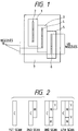
- Fig. 1 shows a construction of a head in a first embodiment of the present invention,
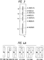
- Fig. 2 illustrates recording by the first embodiment,
- Fig. 3 shows a construction of a head in a second embodiment of the present invention,
- Figs. 4A and 4B illustrate recording by the second embodiment,
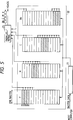
- Fig. 5 shows a conceptual view of a circuit of the second embodiment,
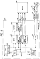
- Fig. 6 shows a circuit diagram of the second embodiment,
- Fig. 7 shows a drive circuit of the head of the second embodiment,
- Fig. 8 shows the second embodiment having a cap applied thereto,
- Fig. 9 shows a perspective view of a recording apparatus to which the present invention may be applied,
- Fig. 10 shows a construction of a head to which the present invention may be applied.
- An embodiment of the present invention is now explained with reference to the drawings.
- A first embodiment of the present invention is shown in Fig. 1. Numeral 1 denotes a head for discharging yellow ink,
numeral 2 denotes a group of discharge port (or ejection orifices) of yellow ink,numeral 3 denotes a head for discharging magenta ink, numeral 4 denotes a group of discharge ports of magenta ink,numeral 5 denotes a head for discharging cyan ink, andnumeral 6 denotes a group of discharge port of cyan ink. 48 nozzles are arranged in each of the heads. As seen from Fig. 1, themagenta head 3 is spaced from thecyan head 5 by 16 nozzle positions along the nozzles. The yellow head 1 is spaced from themagenta head 3 by 16 nozzle position along the nozzles. - A printed result by the above construction is shown in Fig. 2. As seen from Fig. 2, as a carriage on which the heads are mounted scans over a record sheet, swaths of the respective colors appear on the record sheet. The joint of the swaths, that is, the portion recorded by the nozzles at the ends of the nozzle groups of the respective colors is spaced from the joints of other two colors by the same distance so that the ununiformity of density is evenly distributed on the record sheet and it is hard to be noticed. For example, when a nozzle density is set to 360 dpi which is required for fine color recording, the nozzle pitch is 70.5 µm. In the prior art apparatus, significant ununiformity of density appears at a period of 70.5 x 48 = 3.384 mm, but in the present embodiment, slight ununiformity appears at a short period of 70.5 x 16 = 1.128 mm and an overall quality is not substantially lowered.
- An image was formed with shifts of 4 nozzle positions and 8 nozzle positions, but the ununiformity of the colors appeared closely and sharp ununiformity of density appeared at a pitch of approximately 48 nozzles. When the shifts were increased to 14-18 nozzle positions, the ununiformity was substantially not observed. Thus, the overall image quality can be kept by evenly distributing the joints of the colors.
- Further, in order to improve the image quality and the character grade, a head for discharging black ink may be added to the above three heads. In this case, the amount of implantation (discharge) of the black ink to the image is smaller than those of other three inks and the ununiformity is hard to be noticed. Accordingly, a positional relation with the heads of other colors may be arbitrarily.
- In the present embodiment, since the heads are arranged by shifting 16 nozzle positions along the nozzles, that is, a multiple of 8 nozzle positions, a circuit scale may be small and the control is facilitated as will be explained in a second embodiment.
- A second embodiment of the present invention is shown in Fig. 3. Numeral 11 denotes a single recording head,
numeral 12 denotes a group of discharge ports for discharging yellow (Y) ink,numeral 13 denotes a group of discharge ports for discharging magenta (M) ink,numeral 14 denotes a group of discharge ports for discharging cyan (C) ink andnumeral 15 denotes a group of discharge ports for discharging black (Bk) ink. The number of nozzles of each of the Y, M and C nozzle groups is 24, and that for the Bk nozzle group is 64. A spacing between the Y and M, and M and C nozzle groups corresponds to 8-nozzle pitch, and that between the C and Bk nozzle groups corresponds to 16-nozzle pitch. - A printed result by the above construction is shown in Figs. 4A and 4B. In the drawings, a unit of sub-scan is 24 dots and 24 of 64 nozzles are black nozzles. Fig. 4A shows a print process of a first line of Fig. 4B. As seen from Figs. 4A and 4B, the present embodiment attains the same effect as that of the first embodiment. As shown in Japanese Laid-Open Patent Application No. 1-208143, by spacing the nozzle groups from each other by one dot or more, the contact of inks of different colors on the record sheet in one carriage scan is prevented and the deterioration of the image quality due to the mixture of unfixed inks is prevented.
- Further, since the single head is used, the apparatus is of low cost. The 64 black nozzles are provided to permit high speed printing for continuous black-only image by using all black nozzles.
- A conceptual view of the circuit of the present embodiment is shown in Fig. 5. Image data sent from a host computer is normally raster data, but in order to record it by the head of the present embodiment, the data along the raster (line) must be converted to data along the nozzle line. Thus, when it is transferred from a
reception buffer 21 to adrawing buffer 22, the data for 8 nozzles in the raster (line direction) are collectively stored in the buffer for each unit (byte) of data for 8 nozzles. Theprint buffer 22 has a predetermined number of such one-raster (line) buffers, and in printing, three bytes (24 nozzles) are sequentially read from three Y buffers, and the bytes are sequentially read from the M, C and Bk buffers. The plurality of line buffers may be formed by a memory. - The Y, M, C and Bk 8-bit (1 byte) data read from the
print buffer 22 are converted to serial data (bit by bit) by a parallel to-serial converter 23 and they are supplied to the recording head. Since the data of the respective colors are supplied to the head serially, the number of wires of the head is reduced. The data may be supplied to the head parallelly without the parallel-to-serial conversion. - Since the nozzles for the respective colors are arranged offset to the record sheet, the signals to be simultaneously recorded in one scan is read from different portions of the draw data of the respective colors. Namely, the data in the hatched area in Fig. 5 is recorded. In order to simply implement it, it is desirable that a difference between the data read positions of the respective colors is one byte, that is, the spacing between the nozzle groups of the respective colors corresponds to 8 nozzles.
- If it corresponds to 4 nozzles, it is necessary to use a 4-bit organized buffer in a circuit configuration or add a circuit to shift data four bits after it reads the data. In the former case, the number of buffers increases and in the latter case, the number of circuits increases. Thus, both are not desirable. Accordingly, the 24 nozzles and the 8-nozzle spacing in the present embodiment is a most preferable configuration. From the standpoint of circuit configuration, the effect is same so long as the spacing of the nozzle groups is selected by bytes. In other words, the spacing of the nozzle groups may be a multiple of 8-nozzle pitch.
- Fig. 6 shows a block diagram of a configuration of a printer in the present embodiment.
- In Fig. 6, numeral 601 denotes a control unit which controls the overall printer.
Numeral 602 denotes a CPU such as a microprocessor, numeral 603 denotes a ROM which stores a control program to be executed by theCPU 602 and various data, and numeral 604 denotes a RAM which is used as a work area when theCPU 602 executes various processes and temporarily stores various data.Numeral 605 denotes a frequency divider which has a clock source of 16 MHz and supplies various clock signals 1T-32T having periods of 125 ns to 4µs. When theCPU 602 outputs a print section signal S₁, a timing signal having an ink discharge period during the high level period of the signal S₁ is outputted from anoscillator 606. In the present embodiment, since the discharge period of thehead 600 is 185 µs (5.405 KHz), theoscillator 606 receives the clock 8T (1 µs period) from thefrequency divider 605 and outputs the clock signal of 5.405 KHz in the high level period. -
Numeral 607 denotes a DMCA (DMA controller). When start of DMA transfer is commanded from theCPU 602, it reads data from a memory (DRAM) 608 at every 185 µs and supplies it to a parallel-to-serial converter 609, which converts the parallel data transferred from thememory 608 to the DMA to serial data and transfers it to a shift register of thehead 2.Numeral 610 denotes a data transfer control unit which outputs a latch signal (LATCH) to a latch circuit of thehead 2. Atiming control circuit 611 provides a drive pulse for thehead 2 and a block signal (3 bits) to be driven. -
Numeral 613 denotes an input/output port (I/O), and corresponding motors (aCR motor 616 and an LF motor 617) are driven bydrivers port 613. While not shown in Fig. 6, a temperature control heater may be provided with thehead 600 and an appropriate power may be supplied thereto to keep the temperature of thehead 600 constant. - Fig. 7 shows a block diagram of the
head 600. -
Numeral 700 shows a 72-bit shift register which sores serial data (SD) transferred in synchronism with a serial clock (CLK).Numeral 701 denotes a latch circuit which latches the 72-bit data outputted from theshift register 700 by a latch signal (LATCH).Numeral 703 denotes a driver for driving the nozzles for 72 bits.Numeral 710 denotes a decoder which receives a 3-bit signal S11 from atiming control unit 111 and selectively outputs Q₁ to Q₈ in accordance with the three bits to determine the block to be driven. - The
head 600 is constructed by three-color nozzles, that is, 72 nozzles (24 x 3) are constructed by 8 blocks with each block having 9 nozzles (for example, 1, 9, ...65). When the signal S₁₁ is applied to the decoder 10, the block to be activated is determined in accordance with the content thereof. On the other hand, a drive pulse corresponding to the color is applied as a signal S₁₂ and the amount of discharge of the ink of the corresponding color is determined in accordance with a pulse width of the signal S₁₂. For the Bk ink, the circuit configuration of the head is identical to that of the head shown in Fig. 7 except that the shift register is modified from 72 bits to 64 bits. The Bk circuit is serially connected in front of the Y, M and C circuits. - In the present embodiment, the spacing between C and Bk is 16 nozzle positions. Since the implantation of Bk to the image is smaller than those of other colors as described above, the positional relation to other Y, M, and C nozzle groups is not sensitive on the image. A feature of the present construction permits the provision of two nozzle caps. Namely, when the nozzle pitch is 70.5 µm (360 dpi), the 8-nozzle spacing corresponds to 70.5 x 8 = 0.564 mm and it is not easy to provide a partition therebetween while maintaining airtight. However, 16-nozzle spacing corresponds to 70.5 x 16 = 1.128 mm and it is possible to provide a partition between Bk and the color as shown in Fig. 8. In Fig. 8, numeral 31 denotes a cap and numeral 32 denotes a sponge. Other numerals denote like elements to those of Fig. 3.
- Where the spacings between Y and M, and M and C are 16 nozzle positions, a nozzle cap may be used for each color. Since the ununiformity is evenly distributed in this case, the image quality is not lowered.
- Fig. 9 shows a perspective view of an ink jet printer to which the present invention may be applied.
- A
carriage 101 carries aprint head 102 and acartridge 103 and is scanned over aguide shaft 104 and aguide shaft 105. Arecord sheet 106 is fed into the apparatus by afeed roller 107 and fed to a front of afeed roller 108 while it is pinched by thefeed roller 108, a pinch roller (not shown) and asheet retainer 109. Acolor ink cartridge 110 which accommodates three colors, yellow, magenta and cyan and ablack ink cartridge 111 are separately loaded in acartridge 103 which is linked to theprint head 102. - The
print head 102 is explained in more detail with reference to Fig. 10. The yellow, magenta, cyan and black discharging port groups are arranged in a line on the front of theprint head 102. Each group has 24 discharge ports for each of yellow, magenta and cyan, and 64 discharge ports for black. The spacing between the color groups is 8 nozzle positions, and the spacing between the color group and the black group is 16 nozzle positions. Those nozzles are arranged at a density of 360 per inch (360 dpi). - An ink path connected to the discharge port is provided for each of the discharge ports, and a common liquid chamber for supplying ink to the liquid path is provided on the rear of the ink paths. An electro-thermal transducer for generating thermal energy to be used to discharge the ink droplet from the discharge port and an electrode wiring for supplying a power thereto are provided to the ink path corresponding to each discharge port. The electro-thermal transducers and the electrode wirings are formed on a
silicon substrate 201 by film forming technique. Resin, an isolation layer made of glass and a top layer are laminated on the substrate to form the discharge ports, ink paths and common liquid chamber. A drive circuit for driving the electro-thermal transducers in accordance with an electrical signal is provided in a form of a printed circuit board on the rear thereof. - The
silicon substrate 202 and the printed circuit board are parallel to analuminum plate 203, and pipes 204 - 207 project from aplastic member 208 called a distributor which is extended normally to the silicon substrate and they communicate with the flow paths which communicate with the common liquid chamber. - The four flow paths for yellow, magenta, cyan and black are provided in the distributor and they communicate with the respective common liquid chambers through pipes.
- Ink of approximately 40 ng is discharged from each of the yellow, magenta and cyan discharge ports provided in the
print head 102 and ink of approximately 80 ng is discharged from the black discharge port at a frequency of 5.4 KHz. - The
print head 102 is provided with 24 discharge ports for each of yellow, magenta and cyan, and 64 discharge ports for black. This permits high speed printing by using all black nozzles when a black-only image continues. Where a color image is mixedly present, 24 nozzles which are same in number to that of the color discharge ports are used for printing. - The present invention is particularly suitably usable in an ink jet recording head and a recording apparatus in which thermal energy by an electro-thermal transducer, a laser beam or the like is used to cause a change of state of the ink to eject or discharge the ink, because the high density of pixels and high resolution of recording are attained.
- The typical construction and the operational principles are preferably the ones disclosed in USP 4,723,129 and USP 4,740,796. The principle and the structure are applicable to a so-called on-demand type recording system and a continuous type recording system. Particularly, however, it is suitable for the on-demand type because the principle is such that at least one driving signal is applied to an electro-thermal transducer disposed on a liquid (ink) retaining sheet or liquid passage, the driving signal being large enough to provide such a quick temperature rise beyond a departure from nucleation boiling point, by which the thermal energy is provided by the electro-thermal transducer to produce film boiling on the heating portion of the recording head, whereby a bubble can be formed in the liquid (ink) corresponding to each of the driving signals. By the generation, development and contraction of the bubbles, the liquid (ink) is ejected through a discharge port to produce at least one droplet. The driving signal is preferably in the form of pulse because the development and the contraction of the bubbles can be effected instantaneously, and therefore the liquid (ink) is ejected with fast response. The driving signal is preferably such as those disclosed in USP 4,463,359 and USP 4,345,262. In addition, the temperature rise rate of the heating surface is preferably such as those disclosed in USP 4,313,124.
- The structure of the recording head may be those shown in USP 4,558,333 and USP 4,459,600 in which the heating portion is disposed at a bent portion, as well as the structure of the combination of the ejection outlet, liquid passage and the electro-thermal transducer disclosed in the above-mentioned patents. In addition, the present invention is applicable to the structure disclosed in Japanese Laid-Open Patent Application No. 59-123670 in which a common slit is used as the discharge port for a plurality of electro-thermal transducers, and the structure disclosed in Japanese Laid-Open Patent Application No. 59-138461 in which an opening for absorbing a pressure wave of thermal energy is formed corresponding to the discharge port. This is because the present invention is effective to preform the recording with certainty and high efficiency irrespective of the type of the recording head.
- Further, the present invention is applicable to a serial type recording head in which the recording head is fixed on a main assembly, to a replaceable chip type recording head which is connected electrically with the apparatus and can be supplied with the ink when it is mounted in the main assembly, or to a cartridge type recording head having an integral ink container.
- The provision of the recovery means and/or the auxiliary means for the preliminary operation are preferable because they further stabilize the effects of the present invention. As for such means, there are capping means for the recording head, cleaning means therefor, pressing or sucking means, preliminary heating means which may be an electro-thermal transducer, an additional heating element or a combination thereof. Also, means for effecting preliminary discharge (not for the recording) may stabilize the recording operation.
- As regards the variation of the recording head mountable, it may be a single for a single color or plural for a plurality of inks having different colors or densities. The present invention is effectively applicable to an apparatus having at least one of a monochromatic mode mainly with black, a multi-color mode with different color inks and/or full color mode using the mixture of colors, which may be an integrally formed recording unit or a combination of a plurality of recording heads.
- Furthermore, in the foregoing embodiment, the ink is liquid. Alternatively, ink which is solidified below a room temperature and liquefied at a room temperature may be used. Since the ink is controlled within a temperature range of not lower than 30°C and not higher than 70°C to stabilize the viscosity of the ink to provide the stable discharge in a conventional recording apparatus of this type, the ink may be such that it is liquid within the temperature range when the recording signal is supplied. The present invention is applicable to other type of ink. In one of them, the temperature rise due to the thermal energy is positively prevented by consuming it for the state change of the ink from the solid state to the liquid state. Other ink which is solidified when it is left is used to prevent the evaporation of the ink. In any case, by the application of the recording signal producing thermal energy, the ink is liquefied and the liquefied ink may be discharged. Other ink may start to be solidified at the time when it reaches the recording sheet. The present invention is also applicable to the ink which is liquefied by the application of the thermal energy. Such ink may be retained in liquid state or solid state in holes or recesses formed in a porous sheet as disclosed in Japanese Laid-Open Paten Application No. 54-56,847 and Japanese Laid-Open Patent Application No. 60-71,260. The sheet is face to the electro-thermal transducers. The most effective one of the inks described above is the film boiling system.
- The ink jet recording apparatus may be used as an output terminal of an information processing apparatus such as a computer or the like, as a copying machine combined with an image reader or the like, or as a facsimile machine having information sending and receiving functions.
- While the invention has been described with reference to the structures disclosed herein, it is not confined to the details set forth and the present invention is intended to cover such modifications or changes as may come within the objects of the improvements or the scope of the claims.
- In accordance with the present invention, the joints of colors are arranged at a constant interval so that a high grade color image is attained with a minimum cost.
- Since the discharge port groups of the respective colors are shifted form each other by 8n times of the discharge port pitch, the control to reading data is facilitated.
Claims (15)
- An ink jet recording apparatus for discharging inks of at least three primary colors to repeatedly form swaths of respective colors on a recording medium to complete a record, comprising:
at least three groups of discharge ports each having a plurality of discharge ports for discharging the inks of at least the three primary colors; and
scan means for scanning said discharge port groups to the recording medium;
said discharge port groups being spaced from each other by a distance L in a direction different from the scan direction by said scan means;
said distance L between said discharge port groups being 8n (n is a positive integer) times of a discharge port pitch P and selected such that joints of swaths of each color are spaced from joints of swaths of other two colors by a substantially equal distance. - An ink jet recording apparatus according to Claim 1 wherein said discharge port groups and said discharge ports are arranged on one line.
- An ink jet recording apparatus according to Claim 1 wherein said distance L is substantially equal to (3m-1)/3 or (3m-2)/3 of the width of each discharge port group (the number of discharge ports x the discharge port pitch P).
- An ink jet recording apparatus according to Claim 1 wherein said discharge port groups are formed in one recording head.
- An ink jet recording apparatus according to Claim 1 further comprising:
a discharge port group having a plurality of discharge ports for discharging black ink other than said three primary colors;
a distance L2 between said black discharge port group and the discharge port group of other color closest to said black discharge port group having the following relation with the distance L;
- An ink jet recording apparatus according to Claim 5 wherein the number of discharge ports of said black discharge port group is larger than the number of discharge ports of each of discharge port groups of other colors.
- An ink jet recording apparatus according to Claim 6 wherein said discharge port groups are formed in one recording head.
- An ink jet recording apparatus according to Claim 7 wherein said discharge port groups and said discharge ports are arranged on one line.
- An ink jet recording apparatus according to Claim 1 further comprising:
an image memory for storing image data corresponding to said discharge port groups;
said image memory supplying image data to the corresponding discharge port groups on 8 bits basis. - An ink jet recording apparatus according to any one of Claims 1 to 9 wherein said discharge ports discharge inks by using thermal energy.
- Amethod of ink jet recording by discharging inks of at least three primary colors to repeatedly form swaths of colors on a recording medium to complete a record, comprising the steps of:
providing at least three discharge port groups each having a plurality of discharge ports for discharging the inks of at least three primary colors;
said discharge port groups being arranged with a spacing L from each other with the distance L between the discharge port groups being 8n (n is a positive integer) times of a discharge port pitch P;
scanning said discharge port groups to the recording medium in a direction different from the direction of arrangement of said discharge port groups; and
supplying image data corresponding to said discharge port groups from an image memory on 8 bits basis. - A method of ink jet recording apparatus according to Claim 11 wherein said discharge port groups and said discharge ports are arranged on one line.
- A method of ink jet recording apparatus according to Claim 11 wherein said distance L is substantially equal to (3m-1)/3 or (3m-2)/3 of the width of each discharge port group (the number of discharge ports x the discharge port pitch P).
- A method of ink jet recording apparatus according to Claim 11 wherein said discharge port groups are arranged on one line.
- An ink jet recording apparatus according to any one of Claims 11 to 14 wherein said discharge ports discharge inks by using thermal energy.
Applications Claiming Priority (3)
| Application Number | Priority Date | Filing Date | Title |
|---|---|---|---|
| JP293006/92 | 1992-10-30 | ||
| JP29300692A JP3210098B2 (en) | 1992-10-30 | 1992-10-30 | Ink jet recording apparatus and ink jet recording method |
| JP29300692 | 1992-10-30 |
Publications (3)
| Publication Number | Publication Date |
|---|---|
| EP0595658A2 true EP0595658A2 (en) | 1994-05-04 |
| EP0595658A3 EP0595658A3 (en) | 1994-08-17 |
| EP0595658B1 EP0595658B1 (en) | 1999-09-29 |
Family
ID=17789261
Family Applications (1)
| Application Number | Title | Priority Date | Filing Date |
|---|---|---|---|
| EP93308687A Expired - Lifetime EP0595658B1 (en) | 1992-10-30 | 1993-10-29 | Ink jet recording apparatus |
Country Status (6)
| Country | Link |
|---|---|
| US (1) | US5956056A (en) |
| EP (1) | EP0595658B1 (en) |
| JP (1) | JP3210098B2 (en) |
| AT (1) | ATE185109T1 (en) |
| DE (1) | DE69326591T2 (en) |
| ES (1) | ES2137229T3 (en) |
Cited By (12)
| Publication number | Priority date | Publication date | Assignee | Title |
|---|---|---|---|---|
| EP0608105A2 (en) * | 1993-01-19 | 1994-07-27 | Canon Kabushiki Kaisha | Colour ink-jet recording apparatus |
| EP0730968A1 (en) * | 1995-03-06 | 1996-09-11 | Hewlett-Packard Company | Resolution-dependent and color-dependent print masking |
| EP0730970A2 (en) * | 1995-03-07 | 1996-09-11 | OLIVETTI-CANON INDUSTRIALE S.p.A. | Ink-jet colour printer |
| EP0754553A2 (en) * | 1995-07-19 | 1997-01-22 | Canon Kabushiki Kaisha | Color filter manufacturing method and apparatus |
| US5754198A (en) * | 1994-12-06 | 1998-05-19 | Olympus Optical Co., Ltd. | Ink jet printer |
| US5808635A (en) * | 1996-05-06 | 1998-09-15 | Xerox Corporation | Multiple die assembly printbar with die spacing less than an active print length |
| WO1999011461A1 (en) * | 1997-08-29 | 1999-03-11 | Topaz Technologies, Inc. | Integrated head assembly for an ink jet printer |
| US5949454A (en) * | 1994-07-29 | 1999-09-07 | Canon Kabushiki Kaisha | Ink jet head, ink jet head cartridge, ink jet recording apparatus and method for making ink jet head |
| GB2352211A (en) * | 1999-05-14 | 2001-01-24 | Hewlett Packard Co | Simultaneous inkjet printing on two separate sequentially fed sheets of paper |
| US6257699B1 (en) | 1999-10-13 | 2001-07-10 | Xerox Corporation | Modular carriage assembly for use with high-speed, high-performance, printing device |
| GB2357997A (en) * | 2000-01-07 | 2001-07-11 | Hewlett Packard Co | Printhead arrangement to eliminate bi-directional hue shifting |
| EP1228880A2 (en) * | 2001-02-06 | 2002-08-07 | Canon Kabushiki Kaisha | Ink-jet printing apparatus and ink-jet printing method |
Families Citing this family (16)
| Publication number | Priority date | Publication date | Assignee | Title |
|---|---|---|---|---|
| JP3313884B2 (en) * | 1994-05-31 | 2002-08-12 | キヤノン株式会社 | Inkjet recording method |
| US6323890B1 (en) * | 1997-05-13 | 2001-11-27 | Canon Kabushiki Kaisha | Print head and image formation apparatus |
| JPH1142769A (en) * | 1997-07-25 | 1999-02-16 | Brother Ind Ltd | Printer |
| JP3595743B2 (en) | 1998-10-27 | 2004-12-02 | キヤノン株式会社 | Ink tank, cartridge including the ink tank, and recording apparatus using the cartridge |
| JP2001171119A (en) | 1999-12-22 | 2001-06-26 | Canon Inc | Liquid ejection recording head |
| US7014286B2 (en) * | 2000-04-11 | 2006-03-21 | Seiko Epson Corporation | Liquid jetting apparatus |
| JP2002086732A (en) | 2000-09-12 | 2002-03-26 | Canon Inc | Ink jet recording head, ink jet recorder and electronic device |
| US6582055B1 (en) | 2001-08-07 | 2003-06-24 | Lexmark International, Inc. | Method for operating a printer having vertically offset printheads |
| EP1607912B1 (en) * | 2001-10-02 | 2013-03-20 | Francotyp-Postalia GmbH | Method and device for opening a security housing |
| JP4236251B2 (en) * | 2002-04-23 | 2009-03-11 | キヤノン株式会社 | Inkjet head |
| US7118191B2 (en) * | 2004-06-28 | 2006-10-10 | Lexmark International, Inc. | Apparatus and method for ink jet printing using variable interlacing |
| JP4724490B2 (en) * | 2005-08-09 | 2011-07-13 | キヤノン株式会社 | Liquid discharge head |
| JP2008018556A (en) * | 2006-07-11 | 2008-01-31 | Canon Inc | Inkjet recording head |
| US8400676B2 (en) * | 2009-09-30 | 2013-03-19 | Konica Minolta Laboratory U.S.A., Inc. | In place line splitting process and method for multiple beam printers |
| US8931869B2 (en) * | 2011-08-18 | 2015-01-13 | Canon Kabushiki Kaisha | Inkjet printing apparatus and inkjet printing method |
| DE202018102465U1 (en) | 2018-05-03 | 2018-05-14 | Francotyp-Postalia Gmbh | Good processing device with an inkjet printhead |
Citations (4)
| Publication number | Priority date | Publication date | Assignee | Title |
|---|---|---|---|---|
| JPH01208143A (en) * | 1988-02-17 | 1989-08-22 | Canon Inc | Head arrangement structure of color ink jet printer |
| EP0396982A2 (en) * | 1989-04-28 | 1990-11-14 | Canon Kabushiki Kaisha | Recording device and recording method |
| EP0401575A1 (en) * | 1989-06-05 | 1990-12-12 | Siemens Aktiengesellschaft | Print head for ink jet recording apparatus |
| EP0481829A2 (en) * | 1990-10-19 | 1992-04-22 | Hewlett-Packard Company | High definition thermal ink-jet printer |
Family Cites Families (21)
| Publication number | Priority date | Publication date | Assignee | Title |
|---|---|---|---|---|
| CA1127227A (en) * | 1977-10-03 | 1982-07-06 | Ichiro Endo | Liquid jet recording process and apparatus therefor |
| JPS5936879B2 (en) * | 1977-10-14 | 1984-09-06 | キヤノン株式会社 | Thermal transfer recording medium |
| US4330787A (en) * | 1978-10-31 | 1982-05-18 | Canon Kabushiki Kaisha | Liquid jet recording device |
| US4345262A (en) * | 1979-02-19 | 1982-08-17 | Canon Kabushiki Kaisha | Ink jet recording method |
| US4463359A (en) * | 1979-04-02 | 1984-07-31 | Canon Kabushiki Kaisha | Droplet generating method and apparatus thereof |
| US4313124A (en) * | 1979-05-18 | 1982-01-26 | Canon Kabushiki Kaisha | Liquid jet recording process and liquid jet recording head |
| DE2925812C2 (en) * | 1979-06-26 | 1982-10-21 | Siemens AG, 1000 Berlin und 8000 München | Ink printing device for multi-colored printing on a recording medium |
| US4558333A (en) * | 1981-07-09 | 1985-12-10 | Canon Kabushiki Kaisha | Liquid jet recording head |
| US4528576A (en) * | 1982-04-15 | 1985-07-09 | Canon Kabushiki Kaisha | Recording apparatus |
| JPS59123670A (en) * | 1982-12-28 | 1984-07-17 | Canon Inc | Ink jet head |
| JPS59138461A (en) * | 1983-01-28 | 1984-08-08 | Canon Inc | Liquid jet recording apparatus |
| JPS6071260A (en) * | 1983-09-28 | 1985-04-23 | Erumu:Kk | Recorder |
| JPS60120066A (en) * | 1983-12-02 | 1985-06-27 | Ricoh Co Ltd | Charge control type color inkjet printer |
| DE3412531A1 (en) * | 1984-04-04 | 1985-10-17 | Olympia Werke Ag, 2940 Wilhelmshaven | Ink jet printing mechanism for multicolour printing on a recording medium |
| JPS61237648A (en) * | 1985-04-15 | 1986-10-22 | Sharp Corp | Printing head of ink jet printer |
| US4855752A (en) * | 1987-06-01 | 1989-08-08 | Hewlett-Packard Company | Method of improving dot-on-dot graphics area-fill using an ink-jet device |
| JP2731908B2 (en) * | 1988-05-27 | 1998-03-25 | セイコーインスツルメンツ株式会社 | Printer driving method |
| US4908638A (en) * | 1988-12-15 | 1990-03-13 | Xerox Corporation | Ink jet marking head having multicolor capability |
| US5012257A (en) * | 1990-03-16 | 1991-04-30 | Hewlett-Packard Company | Ink jet color graphics printing |
| EP0455467B1 (en) * | 1990-05-02 | 1997-08-20 | Canon Kabushiki Kaisha | Color printer |
| US5208605A (en) * | 1991-10-03 | 1993-05-04 | Xerox Corporation | Multi-resolution roofshooter printheads |
-
1992
- 1992-10-30 JP JP29300692A patent/JP3210098B2/en not_active Expired - Fee Related
-
1993
- 1993-10-29 EP EP93308687A patent/EP0595658B1/en not_active Expired - Lifetime
- 1993-10-29 AT AT93308687T patent/ATE185109T1/en not_active IP Right Cessation
- 1993-10-29 DE DE69326591T patent/DE69326591T2/en not_active Expired - Lifetime
- 1993-10-29 US US08/143,131 patent/US5956056A/en not_active Expired - Lifetime
- 1993-10-29 ES ES93308687T patent/ES2137229T3/en not_active Expired - Lifetime
Patent Citations (4)
| Publication number | Priority date | Publication date | Assignee | Title |
|---|---|---|---|---|
| JPH01208143A (en) * | 1988-02-17 | 1989-08-22 | Canon Inc | Head arrangement structure of color ink jet printer |
| EP0396982A2 (en) * | 1989-04-28 | 1990-11-14 | Canon Kabushiki Kaisha | Recording device and recording method |
| EP0401575A1 (en) * | 1989-06-05 | 1990-12-12 | Siemens Aktiengesellschaft | Print head for ink jet recording apparatus |
| EP0481829A2 (en) * | 1990-10-19 | 1992-04-22 | Hewlett-Packard Company | High definition thermal ink-jet printer |
Non-Patent Citations (1)
| Title |
|---|
| PATENT ABSTRACTS OF JAPAN vol. 13, no. 514 (M-894)17 November 1989 & JP-A-01 208 143 (CANON INC.) * |
Cited By (27)
| Publication number | Priority date | Publication date | Assignee | Title |
|---|---|---|---|---|
| EP0608105A2 (en) * | 1993-01-19 | 1994-07-27 | Canon Kabushiki Kaisha | Colour ink-jet recording apparatus |
| EP0608105B1 (en) * | 1993-01-19 | 1999-10-27 | Canon Kabushiki Kaisha | Colour ink-jet recording apparatus |
| US5903289A (en) * | 1993-01-19 | 1999-05-11 | Canon Kabushiki Kaisha | Control circuit of a compact recording apparatus |
| US5883644A (en) * | 1993-10-29 | 1999-03-16 | Hewlett-Packard Company | Resolution-dependent and color-dependent print masking |
| EP0694400B1 (en) * | 1994-07-29 | 2003-01-08 | Canon Kabushiki Kaisha | Ink jet head, ink jet head cartridge, ink jet recording apparatus and method for making ink jet head |
| US5949454A (en) * | 1994-07-29 | 1999-09-07 | Canon Kabushiki Kaisha | Ink jet head, ink jet head cartridge, ink jet recording apparatus and method for making ink jet head |
| US5754198A (en) * | 1994-12-06 | 1998-05-19 | Olympus Optical Co., Ltd. | Ink jet printer |
| EP0730968A1 (en) * | 1995-03-06 | 1996-09-11 | Hewlett-Packard Company | Resolution-dependent and color-dependent print masking |
| EP0730970A3 (en) * | 1995-03-07 | 1997-09-03 | Olivetti Canon Ind Spa | Ink-jet colour printer |
| EP0730970A2 (en) * | 1995-03-07 | 1996-09-11 | OLIVETTI-CANON INDUSTRIALE S.p.A. | Ink-jet colour printer |
| EP0754553A3 (en) * | 1995-07-19 | 1997-10-08 | Canon Kabushiki Kaisha | Color filter manufacturing method and apparatus, ink-jet device, color filter, display device, and apparatus having display device |
| EP0754553A2 (en) * | 1995-07-19 | 1997-01-22 | Canon Kabushiki Kaisha | Color filter manufacturing method and apparatus |
| US6874883B1 (en) | 1995-07-19 | 2005-04-05 | Canon Kabushiki Kaisha | Color filter manufacturing method and apparatus, ink jet device, color filter, display device, and apparatus having display device |
| US7381444B2 (en) | 1995-07-19 | 2008-06-03 | Canon Kabushiki Kaisha | Color filter manufacturing method and apparatus, ink-jet device, color filter, display device, and apparatus having display device |
| US7270846B2 (en) | 1995-07-19 | 2007-09-18 | Canon Kabushiki Kaisha | Color filter manufacturing method and apparatus, ink-jet device, color filter, display device, and apparatus having display device |
| US5808635A (en) * | 1996-05-06 | 1998-09-15 | Xerox Corporation | Multiple die assembly printbar with die spacing less than an active print length |
| WO1999011461A1 (en) * | 1997-08-29 | 1999-03-11 | Topaz Technologies, Inc. | Integrated head assembly for an ink jet printer |
| GB2352211A (en) * | 1999-05-14 | 2001-01-24 | Hewlett Packard Co | Simultaneous inkjet printing on two separate sequentially fed sheets of paper |
| US6260947B1 (en) | 1999-05-14 | 2001-07-17 | Hewlett-Packard Company | Method and apparatus for multiplexed wet-dye printing |
| GB2352211B (en) * | 1999-05-14 | 2003-02-12 | Hewlett Packard Co | Method and apparatus for multiplexed wet-dye printing |
| US6257699B1 (en) | 1999-10-13 | 2001-07-10 | Xerox Corporation | Modular carriage assembly for use with high-speed, high-performance, printing device |
| US6299287B1 (en) | 2000-01-07 | 2001-10-09 | Hewlett-Packard Company | Printhead arrangement to eliminate bi-directional hue shifting |
| GB2357997B (en) * | 2000-01-07 | 2003-09-10 | Hewlett Packard Co | Printhead arrangement to eliminate bi-directional hue shifting |
| GB2357997A (en) * | 2000-01-07 | 2001-07-11 | Hewlett Packard Co | Printhead arrangement to eliminate bi-directional hue shifting |
| US6764154B2 (en) | 2001-02-06 | 2004-07-20 | Canon Kabushiki Kaisha | Ink-jet printing apparatus and ink-jet printing method |
| EP1228880A3 (en) * | 2001-02-06 | 2003-07-30 | Canon Kabushiki Kaisha | Ink-jet printing apparatus and ink-jet printing method |
| EP1228880A2 (en) * | 2001-02-06 | 2002-08-07 | Canon Kabushiki Kaisha | Ink-jet printing apparatus and ink-jet printing method |
Also Published As
| Publication number | Publication date |
|---|---|
| DE69326591T2 (en) | 2000-05-04 |
| ES2137229T3 (en) | 1999-12-16 |
| JPH06135007A (en) | 1994-05-17 |
| EP0595658B1 (en) | 1999-09-29 |
| US5956056A (en) | 1999-09-21 |
| DE69326591D1 (en) | 1999-11-04 |
| EP0595658A3 (en) | 1994-08-17 |
| ATE185109T1 (en) | 1999-10-15 |
| JP3210098B2 (en) | 2001-09-17 |
Similar Documents
| Publication | Publication Date | Title |
|---|---|---|
| EP0595658B1 (en) | Ink jet recording apparatus | |
| US6312102B1 (en) | Color ink jet recording method and apparatus using black ink and color-mixed black ink | |
| EP0517543B1 (en) | Ink jet recording method | |
| US5896146A (en) | Time division drive recording apparatus and method | |
| EP0595657B1 (en) | Ink jet recording method and ink jet recording apparatus | |
| EP0595651B1 (en) | Ink jet recording system | |
| EP0864424B1 (en) | Ink jet recording apparatus and method for controlling an amount of ink discharged after an inperruption in recording | |
| EP0517520B1 (en) | Ink-jet recording method and ink-jet recording apparatus | |
| US6752485B2 (en) | Printing apparatus and suction recovery control method | |
| US7758154B2 (en) | Inkjet printing apparatus and inkjet printing method | |
| US6655772B2 (en) | Printing apparatus and printhead temperature management method | |
| US6142599A (en) | Method for ink-jet recording and an ink-jet recording apparatus | |
| US6646756B2 (en) | Printing apparatus and method which controls driving of a printing head according to received data | |
| US7126715B2 (en) | Ink jet recording apparatus and control method therefor | |
| JP3483444B2 (en) | Printing apparatus, printing system, and printing method | |
| EP0576285B1 (en) | Ink jet recording method and apparatus | |
| US7315393B2 (en) | Printing system, printer driver, and printing method | |
| JP3297530B2 (en) | Ink jet recording apparatus and ink jet recording method | |
| JP2994884B2 (en) | Inkjet recording method | |
| US6652065B2 (en) | Printing apparatus and control method therefor | |
| JP4532684B2 (en) | Inkjet recording device | |
| US5949449A (en) | Printing apparatus and printing method | |
| JPH07323580A (en) | Ink jet recording method | |
| JP2875641B2 (en) | Inkjet recording method | |
| JPH06191039A (en) | Ink jet recording apparatus |
Legal Events
| Date | Code | Title | Description |
|---|---|---|---|
| PUAI | Public reference made under article 153(3) epc to a published international application that has entered the european phase |
Free format text: ORIGINAL CODE: 0009012 |
|
| AK | Designated contracting states |
Kind code of ref document: A2 Designated state(s): AT BE CH DE DK ES FR GB GR IE IT LI LU NL PT SE |
|
| PUAL | Search report despatched |
Free format text: ORIGINAL CODE: 0009013 |
|
| AK | Designated contracting states |
Kind code of ref document: A3 Designated state(s): AT BE CH DE DK ES FR GB GR IE IT LI LU NL PT SE |
|
| 17P | Request for examination filed |
Effective date: 19950110 |
|
| 17Q | First examination report despatched |
Effective date: 19951206 |
|
| GRAG | Despatch of communication of intention to grant |
Free format text: ORIGINAL CODE: EPIDOS AGRA |
|
| GRAG | Despatch of communication of intention to grant |
Free format text: ORIGINAL CODE: EPIDOS AGRA |
|
| GRAG | Despatch of communication of intention to grant |
Free format text: ORIGINAL CODE: EPIDOS AGRA |
|
| GRAH | Despatch of communication of intention to grant a patent |
Free format text: ORIGINAL CODE: EPIDOS IGRA |
|
| GRAH | Despatch of communication of intention to grant a patent |
Free format text: ORIGINAL CODE: EPIDOS IGRA |
|
| GRAA | (expected) grant |
Free format text: ORIGINAL CODE: 0009210 |
|
| AK | Designated contracting states |
Kind code of ref document: B1 Designated state(s): AT BE CH DE DK ES FR GB GR IE IT LI LU NL PT SE |
|
| PG25 | Lapsed in a contracting state [announced via postgrant information from national office to epo] |
Ref country code: SE Free format text: THE PATENT HAS BEEN ANNULLED BY A DECISION OF A NATIONAL AUTHORITY Effective date: 19990929 Ref country code: LI Free format text: LAPSE BECAUSE OF FAILURE TO SUBMIT A TRANSLATION OF THE DESCRIPTION OR TO PAY THE FEE WITHIN THE PRESCRIBED TIME-LIMIT Effective date: 19990929 Ref country code: GR Free format text: LAPSE BECAUSE OF NON-PAYMENT OF DUE FEES Effective date: 19990929 Ref country code: CH Free format text: LAPSE BECAUSE OF FAILURE TO SUBMIT A TRANSLATION OF THE DESCRIPTION OR TO PAY THE FEE WITHIN THE PRESCRIBED TIME-LIMIT Effective date: 19990929 Ref country code: BE Free format text: LAPSE BECAUSE OF FAILURE TO SUBMIT A TRANSLATION OF THE DESCRIPTION OR TO PAY THE FEE WITHIN THE PRESCRIBED TIME-LIMIT Effective date: 19990929 Ref country code: AT Free format text: LAPSE BECAUSE OF FAILURE TO SUBMIT A TRANSLATION OF THE DESCRIPTION OR TO PAY THE FEE WITHIN THE PRESCRIBED TIME-LIMIT Effective date: 19990929 |
|
| REF | Corresponds to: |
Ref document number: 185109 Country of ref document: AT Date of ref document: 19991015 Kind code of ref document: T |
|
| REG | Reference to a national code |
Ref country code: CH Ref legal event code: EP |
|
| PG25 | Lapsed in a contracting state [announced via postgrant information from national office to epo] |
Ref country code: LU Free format text: LAPSE BECAUSE OF NON-PAYMENT OF DUE FEES Effective date: 19991029 |
|
| REF | Corresponds to: |
Ref document number: 69326591 Country of ref document: DE Date of ref document: 19991104 |
|
| ET | Fr: translation filed | ||
| PG25 | Lapsed in a contracting state [announced via postgrant information from national office to epo] |
Ref country code: IE Free format text: LAPSE BECAUSE OF NON-PAYMENT OF DUE FEES Effective date: 19991129 |
|
| REG | Reference to a national code |
Ref country code: IE Ref legal event code: FG4D |
|
| REG | Reference to a national code |
Ref country code: ES Ref legal event code: FG2A Ref document number: 2137229 Country of ref document: ES Kind code of ref document: T3 |
|
| ITF | It: translation for a ep patent filed |
Owner name: SOCIETA' ITALIANA BREVETTI S.P.A. |
|
| PG25 | Lapsed in a contracting state [announced via postgrant information from national office to epo] |
Ref country code: PT Free format text: LAPSE BECAUSE OF FAILURE TO SUBMIT A TRANSLATION OF THE DESCRIPTION OR TO PAY THE FEE WITHIN THE PRESCRIBED TIME-LIMIT Effective date: 19991229 Ref country code: DK Free format text: LAPSE BECAUSE OF FAILURE TO SUBMIT A TRANSLATION OF THE DESCRIPTION OR TO PAY THE FEE WITHIN THE PRESCRIBED TIME-LIMIT Effective date: 19991229 |
|
| REG | Reference to a national code |
Ref country code: CH Ref legal event code: PL |
|
| PLBE | No opposition filed within time limit |
Free format text: ORIGINAL CODE: 0009261 |
|
| STAA | Information on the status of an ep patent application or granted ep patent |
Free format text: STATUS: NO OPPOSITION FILED WITHIN TIME LIMIT |
|
| 26N | No opposition filed | ||
| REG | Reference to a national code |
Ref country code: IE Ref legal event code: MM4A |
|
| REG | Reference to a national code |
Ref country code: GB Ref legal event code: IF02 |
|
| PGFP | Annual fee paid to national office [announced via postgrant information from national office to epo] |
Ref country code: ES Payment date: 20070910 Year of fee payment: 15 |
|
| PGFP | Annual fee paid to national office [announced via postgrant information from national office to epo] |
Ref country code: NL Payment date: 20071016 Year of fee payment: 15 |
|
| PGFP | Annual fee paid to national office [announced via postgrant information from national office to epo] |
Ref country code: IT Payment date: 20081020 Year of fee payment: 16 |
|
| PGFP | Annual fee paid to national office [announced via postgrant information from national office to epo] |
Ref country code: FR Payment date: 20081024 Year of fee payment: 16 |
|
| NLV4 | Nl: lapsed or anulled due to non-payment of the annual fee |
Effective date: 20090501 |
|
| PG25 | Lapsed in a contracting state [announced via postgrant information from national office to epo] |
Ref country code: NL Free format text: LAPSE BECAUSE OF NON-PAYMENT OF DUE FEES Effective date: 20090501 |
|
| REG | Reference to a national code |
Ref country code: ES Ref legal event code: FD2A Effective date: 20081030 |
|
| PG25 | Lapsed in a contracting state [announced via postgrant information from national office to epo] |
Ref country code: ES Free format text: LAPSE BECAUSE OF NON-PAYMENT OF DUE FEES Effective date: 20081030 |
|
| REG | Reference to a national code |
Ref country code: FR Ref legal event code: ST Effective date: 20100630 |
|
| PG25 | Lapsed in a contracting state [announced via postgrant information from national office to epo] |
Ref country code: FR Free format text: LAPSE BECAUSE OF NON-PAYMENT OF DUE FEES Effective date: 20091102 |
|
| PGFP | Annual fee paid to national office [announced via postgrant information from national office to epo] |
Ref country code: DE Payment date: 20101031 Year of fee payment: 18 |
|
| PG25 | Lapsed in a contracting state [announced via postgrant information from national office to epo] |
Ref country code: IT Free format text: LAPSE BECAUSE OF NON-PAYMENT OF DUE FEES Effective date: 20091029 |
|
| PGFP | Annual fee paid to national office [announced via postgrant information from national office to epo] |
Ref country code: GB Payment date: 20101019 Year of fee payment: 18 |
|
| GBPC | Gb: european patent ceased through non-payment of renewal fee |
Effective date: 20121029 |
|
| PG25 | Lapsed in a contracting state [announced via postgrant information from national office to epo] |
Ref country code: GB Free format text: LAPSE BECAUSE OF NON-PAYMENT OF DUE FEES Effective date: 20121029 Ref country code: DE Free format text: LAPSE BECAUSE OF NON-PAYMENT OF DUE FEES Effective date: 20130501 |
|
| REG | Reference to a national code |
Ref country code: DE Ref legal event code: R119 Ref document number: 69326591 Country of ref document: DE Effective date: 20130501 |