EP0595308A2 - Rapid exchange catheter - Google Patents
Rapid exchange catheter Download PDFInfo
- Publication number
- EP0595308A2 EP0595308A2 EP93117442A EP93117442A EP0595308A2 EP 0595308 A2 EP0595308 A2 EP 0595308A2 EP 93117442 A EP93117442 A EP 93117442A EP 93117442 A EP93117442 A EP 93117442A EP 0595308 A2 EP0595308 A2 EP 0595308A2
- Authority
- EP
- European Patent Office
- Prior art keywords
- lumen
- catheter
- proximal
- distal end
- distal
- Prior art date
- Legal status (The legal status is an assumption and is not a legal conclusion. Google has not performed a legal analysis and makes no representation as to the accuracy of the status listed.)
- Granted
Links
Images

Classifications
-
- A—HUMAN NECESSITIES
- A61—MEDICAL OR VETERINARY SCIENCE; HYGIENE
- A61M—DEVICES FOR INTRODUCING MEDIA INTO, OR ONTO, THE BODY; DEVICES FOR TRANSDUCING BODY MEDIA OR FOR TAKING MEDIA FROM THE BODY; DEVICES FOR PRODUCING OR ENDING SLEEP OR STUPOR
- A61M25/00—Catheters; Hollow probes
- A61M25/10—Balloon catheters
- A61M25/104—Balloon catheters used for angioplasty
-
- A—HUMAN NECESSITIES
- A61—MEDICAL OR VETERINARY SCIENCE; HYGIENE
- A61M—DEVICES FOR INTRODUCING MEDIA INTO, OR ONTO, THE BODY; DEVICES FOR TRANSDUCING BODY MEDIA OR FOR TAKING MEDIA FROM THE BODY; DEVICES FOR PRODUCING OR ENDING SLEEP OR STUPOR
- A61M25/00—Catheters; Hollow probes
- A61M25/10—Balloon catheters
- A61M25/1027—Making of balloon catheters
- A61M25/1036—Making parts for balloon catheter systems, e.g. shafts or distal ends
-
- A—HUMAN NECESSITIES
- A61—MEDICAL OR VETERINARY SCIENCE; HYGIENE
- A61M—DEVICES FOR INTRODUCING MEDIA INTO, OR ONTO, THE BODY; DEVICES FOR TRANSDUCING BODY MEDIA OR FOR TAKING MEDIA FROM THE BODY; DEVICES FOR PRODUCING OR ENDING SLEEP OR STUPOR
- A61M25/00—Catheters; Hollow probes
- A61M25/0043—Catheters; Hollow probes characterised by structural features
- A61M2025/0063—Catheters; Hollow probes characterised by structural features having means, e.g. stylets, mandrils, rods or wires to reinforce or adjust temporarily the stiffness, column strength or pushability of catheters which are already inserted into the human body
-
- A—HUMAN NECESSITIES
- A61—MEDICAL OR VETERINARY SCIENCE; HYGIENE
- A61M—DEVICES FOR INTRODUCING MEDIA INTO, OR ONTO, THE BODY; DEVICES FOR TRANSDUCING BODY MEDIA OR FOR TAKING MEDIA FROM THE BODY; DEVICES FOR PRODUCING OR ENDING SLEEP OR STUPOR
- A61M25/00—Catheters; Hollow probes
- A61M25/01—Introducing, guiding, advancing, emplacing or holding catheters
- A61M2025/0177—Introducing, guiding, advancing, emplacing or holding catheters having external means for receiving guide wires, wires or stiffening members, e.g. loops, clamps or lateral tubes
-
- A—HUMAN NECESSITIES
- A61—MEDICAL OR VETERINARY SCIENCE; HYGIENE
- A61M—DEVICES FOR INTRODUCING MEDIA INTO, OR ONTO, THE BODY; DEVICES FOR TRANSDUCING BODY MEDIA OR FOR TAKING MEDIA FROM THE BODY; DEVICES FOR PRODUCING OR ENDING SLEEP OR STUPOR
- A61M25/00—Catheters; Hollow probes
- A61M25/01—Introducing, guiding, advancing, emplacing or holding catheters
- A61M2025/0183—Rapid exchange or monorail catheters
-
- A—HUMAN NECESSITIES
- A61—MEDICAL OR VETERINARY SCIENCE; HYGIENE
- A61M—DEVICES FOR INTRODUCING MEDIA INTO, OR ONTO, THE BODY; DEVICES FOR TRANSDUCING BODY MEDIA OR FOR TAKING MEDIA FROM THE BODY; DEVICES FOR PRODUCING OR ENDING SLEEP OR STUPOR
- A61M25/00—Catheters; Hollow probes
- A61M25/10—Balloon catheters
- A61M2025/1043—Balloon catheters with special features or adapted for special applications
- A61M2025/1079—Balloon catheters with special features or adapted for special applications having radio-opaque markers in the region of the balloon
-
- A—HUMAN NECESSITIES
- A61—MEDICAL OR VETERINARY SCIENCE; HYGIENE
- A61M—DEVICES FOR INTRODUCING MEDIA INTO, OR ONTO, THE BODY; DEVICES FOR TRANSDUCING BODY MEDIA OR FOR TAKING MEDIA FROM THE BODY; DEVICES FOR PRODUCING OR ENDING SLEEP OR STUPOR
- A61M25/00—Catheters; Hollow probes
- A61M25/10—Balloon catheters
- A61M25/1027—Making of balloon catheters
- A61M25/1029—Production methods of the balloon members, e.g. blow-moulding, extruding, deposition or by wrapping a plurality of layers of balloon material around a mandril
Definitions
- This invention is directed to an angioplasty apparatus for facilitating rapid exchanges. More particularly, this invention is directed to a rapid exchange catheter system whereby a doublelumen dilatation balloon catheter has an opening in one lumen adjacent its distal end for a guidewire and a pushing wire extending through the proximal portion of that same lumen.
- the pushing force on the dilatation catheter is eccentric to the guidewire, such that there is not total responsiveness in the system as the operator attempts to manipulate the dilatation catheter along the guidewire. This can cause binding and failure to move the catheter through tortuous arterial segments and tight stenoses.
- the guidewire lumen is positioned coaxially within a balloon that is attached to the catheter shaft at the proximal and distal ends of the balloon. This arrangement allows the balloon to compress along the guidewire lumen, increasing in profile, and thereby also causing binding and failure to move the catheter.
- balloons of varying lengths may be required.
- a balloon dilatation catheter comprises an elongate, flexible, tubular shaft having two substantially longitudinal coextensive lumens wherein the distal portion of one lumen terminates in a dilatation balloon.
- the other, second lumen is open at its distal end and is interrupted near its distal end to provide an opening for a guidewire that extends distally through the open distal end.
- the second lumen comprises a pushing wire that extends from the proximal portion of the catheter to a point proximal, adjacent, or distal to the opening.
- Figure 1 depicts the distal portion of a balloon dilatation catheter 1 having coextensively extending lumens 2 and 3.
- Lumen 2 terminates in a dilatation balloon 4 which is inflated and deflated through lumen 2.
- Lumens 2 and 3 are preferably each in fluid communication with a hub or fluid communication means 32.
- Lumen 3 contains pushing wire 5, which extends from the proximal end (not shown) of catheter 1 to a position 6 proximal or adjacent to balloon 4.
- the distal portion of pushing wire 5 is secured at position 6 by closure, e.g., heat-shrinking, of lumen 3 or by insertion of a plug or other holding means.
- the distal portion 7 of pushing wire 5 is preferably tapered distally to provide a smooth transition in axial stiffness.
- the pushing wire 5 will become less stiff as the diameter of pushing wire 5 narrows in the distal direction.
- the tapering is substantially linear over the distal portion of the pushing wire 5. Such tapering can extend from about 2 to 40 cm from the distal end of the pushing wire 5.
- the tapering may be stepped, in discrete reductions, or otherwise nonlinear.
- a guidewire 8 is threaded through opening 9 into the enlarged section, i.e., guidewire lumen, 10 of lumen 2. As the guidewire 8 is threaded into section 10, it exits through distal opening 11.
- Figure 2 represents a cross-sectional view showing how lumens 2 and 3 relate to one another and how pushing wire 5 is positioned within lumen 3.
- Lumen walls 12 and 13 can each have a thickness of from about 0.3 to 20 mil, preferably from about 0.5 to 10 mil. Lumen wall 13 will most likely be slightly thicker than lumen wall 12.
- the lumen walls 12 and 13 are comprised of materials conventional to balloon dilatation catheters. Suitable materials include polyolefins such as polyethylene, polyethylene terepthalate, polyurethanes, polyesters, and various copolymers thereof.
- Pushing wire 5 can be made from any rigid, medically acceptable material suitable for such use, including, but not limited to wires or hypotubes comprised of stainless steel or other rigid materials.
- the construction according to the invention leads to flexibility in product design.
- the choice of pushing wire allows the designer to impart various features to the catheter in the form of various flexibility and pushability combinations.
- a hollow pushing wire, or deletion or removal of the pushing wire would facilitate infusion of fluids, drugs, and/or contrast media through the catheter into the distal vasculature.
- catheter 1 may have at least one additional, coextensive lumen that would similarly facilitate infusion of liquids, drugs and/or contrast media.
- a catheter 1 with a third, coextensive lumen open at its distal end could have several possible applications.
- a lubricious coating or a section of thin tubing 14 of lubricious material is sealed into enlarged section 10.
- a lubricious coating or a section of thin tubing 14 of lubricious material is sealed into enlarged section 10.
- materials suitable for this purpose such as polytetrafluoroethylene (available as TEFLON® from duPont), polyethylenes, polysiloxanes, etc.
- the tubing section 14 can hold the distal portion 7 of pushing wire 5 in position.
- a slitting means 31 is mounted proximally on guidewire 8. Then, as the catheter is withdrawn, the enlarged section 10 engages the slitter, the enlarged section 10 is slit, and catheter 1 is separated from guidewire 8. This would eliminate the requirement for the operator to change hands as catheter 1 is removed.
- the catheter 1 may have visual length markings along its shaft that would enable the operator to predict when the catheter 1 would exit the guiding catheter into the vasculature. This would reduce the fluoroscopy time.
- the preferred design would put the markings directly on the pushing wire 5 (heat shrink tubing rings, inks, paints, etc.). Since the pushing wire 5 is encapsulated within the second lumen 3, the markings would not be exposed to the patient (i.e., markings would not come off, and materials which could be toxic if exposed may be used).
- FIG. 3 to 8 The preparation of a catheter 1 according to the invention is shown in Figures 3 to 8. After a double lumen workpiece 20 is prepared, the distal end of the workpiece is sealingly clamped, and heat and inflation pressure are applied to cause the distal portion of lumen 2 to expand to form the wall of balloon 4 and the distal portion of lumen 3 to expand to form enlarged section 10. The location where heat is applied can be varied to vary the respective lengths of balloon 4 and enlarged section 10. Heat sealing or application of suitable adhesive seals the distal portion of balloon 4. Opening 9 is cut into section 10, and opening 11 is maintained or created by trimming the distal portion of the catheter 1.
- Pushing wire 5 is then inserted into lumen 3, wherein either the remaining proximal portion 18, or more, of lumen 3 is heat shrunk to cause pushing wire 5 to be positively engaged by lumen 3.
- the distal portion of pushing wire 5 could be affixed by suitable means, such as an adhesive or a plug, in lumen 3.
- Workpiece 20 can be prepared by methods well-known to those skilled in the art. In a preferred method workpiece 20 can be prepared by blowing extruded tubing 21, a cross-section of which is shown in Fig. 6.
- catheter 1 can be prepared from extruded tubing 21 by blowing said tubing 21 under pressure and heating conditions sufficient to produce a catheter piece 25, a cross-section of which is shown in Fig. 7, where the diameters of lumens 26 and 27 correspond substantially to the final diameters of balloon 4 and enlarged section 10, respectively.
- the holes or openings 22 and 23 in tubing 21 are not necessarily the same, such that the diameters of lumens 26 and 27 may also differ.
- a pushing wire 29 is inserted into lumen 27.
- Pushing wire 29 extends the length of lumen 27 to a point slightly distal of opening 28.
- a lubricious liner 30 is inserted into the distal end of lumen 27.
- the distal end of lumen 26 is sealed, and, while lumen 26 is pressurized, heat is applied to the distal portion of catheter piece 25 to cause lumen 27 to slightly shrink around liner 30, which fixedly engages the distal end of pushing wire 29.
- the portion of catheter piece 25 proximal to the balloon is heated to shrink lumen 26 and to shrink lumen 27 around pushing wire 29.
- the balloon length is determined by the location where heat is applied to lumen 26.
- the heating can be effected by a point source of heat, where the point source is moved along the exterior of the catheter or the catheter is moved across the point source.
- the heat can be applied with a broader heat source, such as a hot water bath.
- the source of and/or techniques of heating will be apparent to those skilled in the art.
- the workpiece will optionally be cross-linked prior to working.
- Such cross-linking could be effected by chemical or irradiation means.
- the workpiece can be optionally or additionally oriented by mechanical means, such as stretching during blowing.
- the catheters of the invention are prepared by use of techniques and procedures known to those skilled in the art.
- the pressure and heating conditions will vary according to the materials used and the results desired, and it is well within the skill of those skilled in the art to determine the proper pressure and heating requirements.
- an additional advantage of the design and preparation according to the invention is that the catheter can be of integral design and multiple bonding steps can be avoided.
- the balloon and both lumens can be formed from a single piece. This design permits improvements in manufacturing yields, quality, and reliability due to simplified construction.
- Guidewire 8 may be a conventional guidewire, preferably a spring guidewire, as is well known. Typical guidewires are shown in U.S. Patents Nos. 4,757,827, 4,815,478, 4,813,434, 4,619,274, 4,554,929, 4,545,390, 4,538,622, 3,906,938, 3,973,556, and 4,719,924, all of which are incorporated herein by reference.
- the shaft of guidewire 8 could be solid or hollow, such as a hypotube, with an open distal end, to facilitate drug infusion.
- a guiding catheter is inserted into the coronary artery in a conventional manner.
- the guidewire 8 is then introduced into the guiding catheter and advanced to and across the lesion.
- the balloon dilatation catheter is inserted onto the guidewire by a back loading technique, where the proximal extremity of the guidewire 8 is inserted backwardly through the tip 11 of the balloon dilatation catheter 1 through the enlarged section 10, and exits opening 9.
- the catheter 1 is then advanced along the guidewire 8 to and across the lesion.
- the balloon 4 After the balloon 4 has crossed the stenosis or lesion, the balloon 4 can be inflated in a conventional manner by introducing a radiopaque contrast liquid through the lumen 2. After the inflation has occurred and the desired operation has been performed by enlarging the opening in the stenosis, the balloon dilatation catheter 1 can be removed very rapidly by holding the guidewire 8 stationary and withdrawing the balloon dilatation catheter.
- the balloon dilatation catheter can be removed and thereafter the guiding catheter can be removed.
Abstract
Description
- This invention is directed to an angioplasty apparatus for facilitating rapid exchanges. More particularly, this invention is directed to a rapid exchange catheter system whereby a doublelumen dilatation balloon catheter has an opening in one lumen adjacent its distal end for a guidewire and a pushing wire extending through the proximal portion of that same lumen.
- During angioplasty procedures it is often necessary to exchange one dilatation catheter for another. To do so requires manipulation of lengthy exchange wires, which is time consuming and awkward to the extent that two operators are required. A current approach to dealing with this is the "monorail" system wherein a dilatation catheter has a structure such that only the distal portion of the catheter tracks a guidewire. Examples of such systems are described in Yock, U.S. Patents Nos. 5,040,548 and 5,061,273, Bonzel, U.S. Patent No. 4,762,129, and Kramer, U.S. Patent No. 5,135,535, all of which are incorporated herein by reference.
- In the known monorail systems the pushing force on the dilatation catheter is eccentric to the guidewire, such that there is not total responsiveness in the system as the operator attempts to manipulate the dilatation catheter along the guidewire. This can cause binding and failure to move the catheter through tortuous arterial segments and tight stenoses. Furthermore, in these systems/designs, the guidewire lumen is positioned coaxially within a balloon that is attached to the catheter shaft at the proximal and distal ends of the balloon. This arrangement allows the balloon to compress along the guidewire lumen, increasing in profile, and thereby also causing binding and failure to move the catheter. Dependent upon the clinical application, balloons of varying lengths may be required. In addition to the time and expense required to develop and qualify separate balloons for each application, as the balloon length increases the tendency for binding increases. Thus, there is a need for a monorail type system wherein there will be co-linear design between a push wire and the guidewire and a parallel arrangement between the balloon and the guidewire lumen, resulting in more positive tracking and facilitated passage through tortuous arterial segments and tight stenoses, as well as simplified methods of manufacture.
- It is an object of the invention to provide a balloon dilatation system capable of rapid exchange.
- It is also an object of the invention to provide a balloon dilatation system wherein a double lumen dilatation catheter has a pushing wire that extends through one lumen to a position adjacent or proximal to the dilatation balloon.
- It is a further object of the invention to provide a double lumen dilatation catheter wherein the guidewire lumen is positioned exterior to the dilatation balloon.
- It is yet a further object of the invention to provide a rapid exchange balloon dilatation catheter that is simple to manufacture.
- These and other objects of the invention will become more apparent from the description below.
-
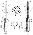
- Fig. 1 depicts a cross-sectional view of the distal portion of a balloon dilatation catheter according to the invention;
- Fig. 2 represents a cross-sectional view along the line 2-2;
- Figs. 3, 5, and 7 represent perspective views of a distal portion of the catheter of the invention as it is being formed; and
- Figs. 4, 6, and 8 represent cross-sectional views of work-pieces from which the catheter of the invention can be formed.
- According to the invention, a balloon dilatation catheter comprises an elongate, flexible, tubular shaft having two substantially longitudinal coextensive lumens wherein the distal portion of one lumen terminates in a dilatation balloon. The other, second lumen is open at its distal end and is interrupted near its distal end to provide an opening for a guidewire that extends distally through the open distal end. Moreover, the second lumen comprises a pushing wire that extends from the proximal portion of the catheter to a point proximal, adjacent, or distal to the opening.
- The invention can perhaps be better appreciated by making reference to the drawings. Figure 1 depicts the distal portion of a
balloon dilatation catheter 1 having coextensively extendinglumens Lumen 2 terminates in adilatation balloon 4 which is inflated and deflated throughlumen 2.Lumens -
Lumen 3 contains pushingwire 5, which extends from the proximal end (not shown) ofcatheter 1 to a position 6 proximal or adjacent toballoon 4. The distal portion of pushingwire 5 is secured at position 6 by closure, e.g., heat-shrinking, oflumen 3 or by insertion of a plug or other holding means. Also, the distal portion 7 of pushingwire 5 is preferably tapered distally to provide a smooth transition in axial stiffness. The pushingwire 5 will become less stiff as the diameter of pushingwire 5 narrows in the distal direction. The tapering is substantially linear over the distal portion of the pushingwire 5. Such tapering can extend from about 2 to 40 cm from the distal end of the pushingwire 5. Optionally, instead of linear tapering, the tapering may be stepped, in discrete reductions, or otherwise nonlinear. - The distal portion of a
guidewire 8 is threaded through opening 9 into the enlarged section, i.e., guidewire lumen, 10 oflumen 2. As theguidewire 8 is threaded intosection 10, it exits throughdistal opening 11. - Figure 2 represents a cross-sectional view showing how
lumens wire 5 is positioned withinlumen 3.Lumen walls Lumen wall 13 will most likely be slightly thicker thanlumen wall 12. - The
lumen walls wire 5 can be made from any rigid, medically acceptable material suitable for such use, including, but not limited to wires or hypotubes comprised of stainless steel or other rigid materials. - The construction according to the invention leads to flexibility in product design. For example, the choice of pushing wire allows the designer to impart various features to the catheter in the form of various flexibility and pushability combinations. Also, a hollow pushing wire, or deletion or removal of the pushing wire, would facilitate infusion of fluids, drugs, and/or contrast media through the catheter into the distal vasculature. Further, it is within the scope of the invention that
catheter 1 may have at least one additional, coextensive lumen that would similarly facilitate infusion of liquids, drugs and/or contrast media. For example, acatheter 1 with a third, coextensive lumen open at its distal end could have several possible applications. - In a preferred embodiment of the invention, as shown in Fig. 1, a lubricious coating or a section of
thin tubing 14 of lubricious material is sealed into enlargedsection 10. There are several known materials suitable for this purpose, such as polytetrafluoroethylene (available as TEFLON® from duPont), polyethylenes, polysiloxanes, etc. In this embodiment thetubing section 14 can hold the distal portion 7 of pushingwire 5 in position. - According to another embodiment of the invention a
slitting means 31 is mounted proximally onguidewire 8. Then, as the catheter is withdrawn, the enlargedsection 10 engages the slitter, the enlargedsection 10 is slit, andcatheter 1 is separated fromguidewire 8. This would eliminate the requirement for the operator to change hands ascatheter 1 is removed. - The
catheter 1 may have visual length markings along its shaft that would enable the operator to predict when thecatheter 1 would exit the guiding catheter into the vasculature. This would reduce the fluoroscopy time. The preferred design would put the markings directly on the pushing wire 5 (heat shrink tubing rings, inks, paints, etc.). Since the pushingwire 5 is encapsulated within thesecond lumen 3, the markings would not be exposed to the patient (i.e., markings would not come off, and materials which could be toxic if exposed may be used). - The preparation of a
catheter 1 according to the invention is shown in Figures 3 to 8. After adouble lumen workpiece 20 is prepared, the distal end of the workpiece is sealingly clamped, and heat and inflation pressure are applied to cause the distal portion oflumen 2 to expand to form the wall ofballoon 4 and the distal portion oflumen 3 to expand to formenlarged section 10. The location where heat is applied can be varied to vary the respective lengths ofballoon 4 andenlarged section 10. Heat sealing or application of suitable adhesive seals the distal portion ofballoon 4. Opening 9 is cut intosection 10, andopening 11 is maintained or created by trimming the distal portion of thecatheter 1. Pushingwire 5 is then inserted intolumen 3, wherein either the remainingproximal portion 18, or more, oflumen 3 is heat shrunk to cause pushingwire 5 to be positively engaged bylumen 3. Alternatively, the distal portion of pushingwire 5 could be affixed by suitable means, such as an adhesive or a plug, inlumen 3. -
Workpiece 20 can be prepared by methods well-known to those skilled in the art. In apreferred method workpiece 20 can be prepared by blowing extrudedtubing 21, a cross-section of which is shown in Fig. 6. - In a preferred embodiment of the invention,
catheter 1 can be prepared fromextruded tubing 21 by blowing saidtubing 21 under pressure and heating conditions sufficient to produce acatheter piece 25, a cross-section of which is shown in Fig. 7, where the diameters oflumens balloon 4 andenlarged section 10, respectively. The holes oropenings tubing 21 are not necessarily the same, such that the diameters oflumens - After an opening 28 (corresponding to opening 9) is cut into
lumen 27 at a point to define the length of the guidewire lumen orenlarged section 10, a pushingwire 29 is inserted intolumen 27. Pushingwire 29 extends the length oflumen 27 to a point slightly distal ofopening 28. Preferably alubricious liner 30 is inserted into the distal end oflumen 27. Then, the distal end oflumen 26 is sealed, and, while lumen 26 is pressurized, heat is applied to the distal portion ofcatheter piece 25 to causelumen 27 to slightly shrink aroundliner 30, which fixedly engages the distal end of pushingwire 29. Next, the portion ofcatheter piece 25 proximal to the balloon is heated to shrinklumen 26 and to shrinklumen 27 around pushingwire 29. The balloon length is determined by the location where heat is applied tolumen 26. - When portions of the catheter are heated, the heating can be effected by a point source of heat, where the point source is moved along the exterior of the catheter or the catheter is moved across the point source. Alternatively, the heat can be applied with a broader heat source, such as a hot water bath. The source of and/or techniques of heating will be apparent to those skilled in the art.
- Also, in a preferred embodiment of the invention the workpiece will optionally be cross-linked prior to working. Such cross-linking could be effected by chemical or irradiation means. The workpiece can be optionally or additionally oriented by mechanical means, such as stretching during blowing.
- The catheters of the invention are prepared by use of techniques and procedures known to those skilled in the art. For example, the pressure and heating conditions will vary according to the materials used and the results desired, and it is well within the skill of those skilled in the art to determine the proper pressure and heating requirements.
- An additional advantage of the design and preparation according to the invention is that the catheter can be of integral design and multiple bonding steps can be avoided. The balloon and both lumens can be formed from a single piece. This design permits improvements in manufacturing yields, quality, and reliability due to simplified construction.
-
Guidewire 8 may be a conventional guidewire, preferably a spring guidewire, as is well known. Typical guidewires are shown in U.S. Patents Nos. 4,757,827, 4,815,478, 4,813,434, 4,619,274, 4,554,929, 4,545,390, 4,538,622, 3,906,938, 3,973,556, and 4,719,924, all of which are incorporated herein by reference. In addition, the shaft ofguidewire 8 could be solid or hollow, such as a hypotube, with an open distal end, to facilitate drug infusion. - Operation and use of the angioplasty apparatus shown in Fig. 1 may now be briefly described as follows: A guiding catheter is inserted into the coronary artery in a conventional manner. The
guidewire 8 is then introduced into the guiding catheter and advanced to and across the lesion. Now, the balloon dilatation catheter is inserted onto the guidewire by a back loading technique, where the proximal extremity of theguidewire 8 is inserted backwardly through thetip 11 of theballoon dilatation catheter 1 through theenlarged section 10, and exits opening 9. Thecatheter 1 is then advanced along theguidewire 8 to and across the lesion. - After the
balloon 4 has crossed the stenosis or lesion, theballoon 4 can be inflated in a conventional manner by introducing a radiopaque contrast liquid through thelumen 2. After the inflation has occurred and the desired operation has been performed by enlarging the opening in the stenosis, theballoon dilatation catheter 1 can be removed very rapidly by holding theguidewire 8 stationary and withdrawing the balloon dilatation catheter. - If it is ascertained by the operator that additional dilatation of the stenosis is desired and that a larger balloon should be inserted into the stenosis, this can be accomplished very rapidly by selecting the desired size of balloon dilation catheter and repeating the aforementioned procedure. The balloon of the new dilatation catheter can be inflated in the same manner as hereinbefore described. If necessary, even another exchange procedure can be readily accomplished in the same manner as hereinbefore described utilizing a still larger balloon dilatation catheter if that turns out to be necessary.
- After the desired amount of dilation of the stenosis or lesion has been accomplished, the balloon dilatation catheter can be removed and thereafter the guiding catheter can be removed.
- The preceding specific embodiments are illustrative of the practice of the invention. It is to be understood, however, that other expedients known to those skilled in the art or disclosed herein, may be employed without departing from the spirit of the invention or the scope of the appended claims.
Claims (24)
- A balloon dilatation catheter which comprises:
an elongate flexible tubular shaft (1) having a proximal end and a distal end;
an inflatable dilatation balloon (4) forming part of the distal end of the shaft, the dilatation balloon (4) having a proximal end and a distal end;
a first, inflation lumen (2) extending through the shaft (1) and having a proximal end and a distal end, the distal end of the first lumen opening into and being in fluid communication with the dilatation balloon (4);
a second lumen (3) extending through the shaft and having a proximal end and a distal end, the distal end of the second lumen (3) being open and the second lumen (3) having a distal portion (10) defined by (i) an opening (9) proximal to the distal end of the second lumen (3) and (ii) the distal end of the second lumen (3), and a proximal portion (18) defined by the portion of the second lumen (3) proximal to said opening, said distal portion (10) being enlarged as compared to the proximal portion (18) to facilitate receiving a guidewire (8) in a sliding fit; and
a pushing wire (5) having a proximal end and a distal end and extending through the second lumen (3), the distal end (7) of the pushing wire (5) being fixed in the second lumen (3) proximal to the distal end of the second lumen (3). - The catheter of Claim 1, wherein the opening (9) of the second lumen (3) is proximal or adjacent to the distal end of the dilatation balloon (4).
- The catheter of Claim 1, wherein the distal end (7) of the pushing wire (5) is positioned at or near the opening (9) of the second lumen (3).
- The catheter of Claim 1, wherein the enlarged portion (10) of the second lumen (3) comprises lubricious material.
- The catheter of Claim 4, wherein the lubricious material is in the form of tubing (14) within the enlarged distal portion (10) of the second lumen (3).
- The catheter of Claim 5, wherein the enlarged distal portion (10) has an inner surface and the distal end (7) of the pushing wire (5) is held in position by the lubricious tubing (14) and said inner surface.
- The catheter of Claim 1, wherein the proximal portion (18) of the second lumen (3) proximal to the opening (9) has been heat shrunk around the pushing wire (5).
- The catheter of Claim 1, wherein the proximal end of the first lumen (2) is connected to a fluid communication means (32) such that the first lumen (2) is in fluid communication with an inflation source.
- The catheter of Claim 1 which comprises at least one additional lumen extending through the tubular shaft (1) and having open proximal and distal ends.
- The catheter of Claim 9, wherein there is one additional lumen.
- The catheter of Claim 10, wherein the proximal end of the additional lumen is connected to a fluid communication means (32) such that the distal end of the lumen is in fluid communication with the fluid communication means (32).
- A balloon dilatation catheter system which comprises a guidewire (8) and two or more catheters (1) of Claim 1, which catheters (1) can be sequentially exchanged over said guidewire (8).
- The system of Claim 12, wherein the guidewire (8) has a splitter (31) for splitting the enlarged portion of the second lumen (3) of each catheter (1).
- The system of Claim 12, wherein each catheter (1) has a dilatation balloon (4) of a different size.
- A method of preparing a balloon dilatation catheter which comprises the steps of:(a) blowing a length of multiple lumen tubing to produce a double lumen catheter piece (20) having distal and proximal ends and having a first lumen (2) and a second lumen (3);(b) cutting an opening (9) in the second lumen (3) proximal to the distal end of the catheter piece (20);(c) inserting a pushing wire (5) having distal (7) and proximal ends into the second lumen (3) through the proximal end of the catheter piece until the distal end (7) of the pushing wire extends distally across the opening (9);(d) inserting a piece of lubricious tubing (14) having proximal and distal ends proximally into the second lumen (3) through the distal end of the catheter piece so that the proximal end of the lubricious tubing (14) is adjacent to or proximal to the distal end (7) of the pushing wire (5);(e) sealing the distal end of the first lumen (2);(f) heating the distal portion of the catheter piece (20) to cause the distal portion of the second lumen (3) to shrink slightly to cause the lubricious tubing (14) to fixedly engage the distal end (7) of the pushing wire (5), while the first lumen (2) is pressurized; and(g) heating the catheter piece (20) proximal to its distal portion to cause the second lumen (3) to shrink around the pushing wire (5) and the first lumen (2) to shrink to define a balloon.
- The method of Claim 15, which comprises the additional step of attaching a fluid communication means (32) to the proximal end of the catheter piece (20) to enable the first lumen (2) to be in fluid communication with an inflation fluid source.
- The method of Claim 15, wherein the tubing blown in step (a) has more than two lumens.
- The method of Claim 17, wherein the tubing has at least one lumen having an open distal end.
- The method of Claim 18, which comprises the additional step of attaching fluid communication means (32) to the proximal end of the catheter (1) to enable the first lumen (2) to be in fluid communication with an inflation fluid source and to enable at least one additional lumen to be in fluid communication with the proximal end of the catheter (1).
- A method of preparing a balloon dilatation catheter which comprises the steps of:(a) blowing a length of multiple lumen tubing to produce a double lumen workpiece (21) having distal and proximal ends and having first (22) and second (23) lumens having respective proximal and distal ends;(b) sealing the distal end of the first lumen (22);(c) inflating the first lumen (22) to cause a dilatation balloon (4) to form in the first lumen (22) proximal to the distal end of the first lumen (22);(d) cutting an opening (9) in the second lumen (23) proximal to the distal end of the catheter workpiece (21);(e) inserting a pushing wire (5) having distal and proximal ends into the second lumen (23) through the proximal end of the catheter workpiece (21) until the distal end (7) of the pushing wire (7) extends distally across the opening (9);(f) inserting a piece of lubricious tubing (14) having proximal and distal ends proximally into the second lumen (23) through the distal end of the catheter workpiece (21) so that the proximal end of the lubricious tubing (14) is adjacent to or proximal to the distal end (7) of the pushing wire (5);(g) heating the distal portion of the catheter workpiece (21) to cause the distal portion of the second lumen (23) to shrink slightly to cause the lubricious tubing (14) to fixedly engage the distal end (7) of the pushing wire (5), while the first lumen (22) is pressurized; and(h) heating the catheter workpiece (21) proximal to its distal portion to cause the second lumen (23) to shrink around the pushing wire (5).
- The method of claim 20, which comprises the additional step of attaching a fluid communication means (32) to the proximal end of the catheter workpiece (21) to enable the first lumen (22) to be in fluid communication with an inflation fluid source.
- The method of Claim 20, wherein the tubing blown in step (a) has more than two lumens.
- The method of Claim 22, wherein the tubing has at least one lumen having an open distal end.
- The method of Claim 23, which comprises the additional step of attaching fluid communication means (32) to the proximal end of the catheter (1) to enable the first lumen (22) to be in fluid communication with the proximal end of the catheter (1).
Applications Claiming Priority (4)
| Application Number | Priority Date | Filing Date | Title |
|---|---|---|---|
| US96988792A | 1992-10-30 | 1992-10-30 | |
| US07/969,946 US5315747A (en) | 1992-10-30 | 1992-10-30 | Method of preparing a balloon dilatation catheter |
| US969887 | 1992-10-30 | ||
| US969946 | 1992-10-30 |
Publications (3)
| Publication Number | Publication Date |
|---|---|
| EP0595308A2 true EP0595308A2 (en) | 1994-05-04 |
| EP0595308A3 EP0595308A3 (en) | 1995-05-17 |
| EP0595308B1 EP0595308B1 (en) | 2001-12-12 |
Family
ID=27130530
Family Applications (1)
| Application Number | Title | Priority Date | Filing Date |
|---|---|---|---|
| EP93117442A Expired - Lifetime EP0595308B1 (en) | 1992-10-30 | 1993-10-27 | Rapid exchange catheter |
Country Status (6)
| Country | Link |
|---|---|
| EP (1) | EP0595308B1 (en) |
| JP (1) | JPH07533A (en) |
| AU (2) | AU5031893A (en) |
| CA (1) | CA2109476C (en) |
| DE (2) | DE4336684A1 (en) |
| ZA (1) | ZA938021B (en) |
Cited By (10)
| Publication number | Priority date | Publication date | Assignee | Title |
|---|---|---|---|---|
| EP0707501A1 (en) * | 1993-07-02 | 1996-04-24 | Ronald J. Solar | Rapid withdrawal catheter |
| EP0707865A1 (en) * | 1994-10-21 | 1996-04-24 | Cordis Europa N.V. | Catheter with guide wire channel |
| NL9401758A (en) * | 1994-10-21 | 1996-06-03 | Cordis Europ | Catheter with guide-wire passage |
| EP0746374A1 (en) * | 1993-10-07 | 1996-12-11 | Boston Scientific Corporation | Dilatation catheter |
| FR2736270A1 (en) * | 1995-07-06 | 1997-01-10 | Nycomed Lab Sa | GUIDE TYPE EXPANSION CATHETER ON A WIRE |
| EP0715531A4 (en) * | 1993-08-24 | 1997-02-05 | Ronald J Solar | Dilatation catheter with eccentric balloon |
| US5632760A (en) * | 1994-10-20 | 1997-05-27 | Cordis Corporation | Balloon catheter for stent implantation |
| EP0805702A1 (en) * | 1994-12-30 | 1997-11-12 | Jaroslav Janacek | Dilation catheter |
| EP0829269A1 (en) * | 1996-09-11 | 1998-03-18 | Schneider (Europe) Ag | Catheter system |
| CN115195130A (en) * | 2022-07-28 | 2022-10-18 | 惠州市顺美医疗科技有限公司 | Welding equipment and process for reinforcing support balloon dilatation catheter |
Families Citing this family (4)
| Publication number | Priority date | Publication date | Assignee | Title |
|---|---|---|---|---|
| US5634902A (en) * | 1995-02-01 | 1997-06-03 | Cordis Corporation | Dilatation catheter with side aperture |
| US5690642A (en) | 1996-01-18 | 1997-11-25 | Cook Incorporated | Rapid exchange stent delivery balloon catheter |
| JPH10290837A (en) * | 1997-04-18 | 1998-11-04 | Kanegafuchi Chem Ind Co Ltd | Balloon catheter and manufacture of multi-lumen shaft used therefor |
| DK1255506T3 (en) * | 2000-02-18 | 2004-01-05 | E V R Endovascular Res Es S A | Endolumenal device for delivering and placing an endolumenal expandable prosthesis |
Citations (6)
| Publication number | Priority date | Publication date | Assignee | Title |
|---|---|---|---|---|
| EP0274129A2 (en) * | 1987-01-06 | 1988-07-13 | Advanced Cardiovascular Systems, Inc. | Reinforced balloon dilatation catheter with slitted exchange sleeve and method |
| EP0365993A1 (en) * | 1988-10-20 | 1990-05-02 | Terumo Kabushiki Kaisha | Catheter equipped with expansible member and method of manufacturing the same |
| US4944745A (en) * | 1988-02-29 | 1990-07-31 | Scimed Life Systems, Inc. | Perfusion balloon catheter |
| US5059177A (en) * | 1990-04-19 | 1991-10-22 | Cordis Corporation | Triple lumen balloon catheter |
| EP0476807A1 (en) * | 1990-09-17 | 1992-03-25 | C.R. Bard, Inc. | Core wire steerable catheters |
| EP0436501B1 (en) * | 1988-10-04 | 1993-04-21 | Cordis Corporation | Balloons for medical devices and fabrication thereof |
-
1993
- 1993-10-27 DE DE4336684A patent/DE4336684A1/en not_active Withdrawn
- 1993-10-27 AU AU50318/93A patent/AU5031893A/en not_active Abandoned
- 1993-10-27 ZA ZA938021A patent/ZA938021B/en unknown
- 1993-10-27 EP EP93117442A patent/EP0595308B1/en not_active Expired - Lifetime
- 1993-10-27 DE DE69331307T patent/DE69331307T2/en not_active Expired - Lifetime
- 1993-10-28 CA CA002109476A patent/CA2109476C/en not_active Expired - Lifetime
- 1993-10-29 JP JP5292368A patent/JPH07533A/en active Pending
-
1997
- 1997-06-20 AU AU26176/97A patent/AU694389B2/en not_active Expired
Patent Citations (6)
| Publication number | Priority date | Publication date | Assignee | Title |
|---|---|---|---|---|
| EP0274129A2 (en) * | 1987-01-06 | 1988-07-13 | Advanced Cardiovascular Systems, Inc. | Reinforced balloon dilatation catheter with slitted exchange sleeve and method |
| US4944745A (en) * | 1988-02-29 | 1990-07-31 | Scimed Life Systems, Inc. | Perfusion balloon catheter |
| EP0436501B1 (en) * | 1988-10-04 | 1993-04-21 | Cordis Corporation | Balloons for medical devices and fabrication thereof |
| EP0365993A1 (en) * | 1988-10-20 | 1990-05-02 | Terumo Kabushiki Kaisha | Catheter equipped with expansible member and method of manufacturing the same |
| US5059177A (en) * | 1990-04-19 | 1991-10-22 | Cordis Corporation | Triple lumen balloon catheter |
| EP0476807A1 (en) * | 1990-09-17 | 1992-03-25 | C.R. Bard, Inc. | Core wire steerable catheters |
Cited By (20)
| Publication number | Priority date | Publication date | Assignee | Title |
|---|---|---|---|---|
| EP0707501A1 (en) * | 1993-07-02 | 1996-04-24 | Ronald J. Solar | Rapid withdrawal catheter |
| EP0707501A4 (en) * | 1993-07-02 | 1997-01-22 | Ronald J Solar | Rapid withdrawal catheter |
| EP0715531A4 (en) * | 1993-08-24 | 1997-02-05 | Ronald J Solar | Dilatation catheter with eccentric balloon |
| US5931812A (en) * | 1993-10-07 | 1999-08-03 | Boston Scientific Corporation | Dilatation catheter |
| EP0746374A1 (en) * | 1993-10-07 | 1996-12-11 | Boston Scientific Corporation | Dilatation catheter |
| EP0746374A4 (en) * | 1993-10-07 | 1997-05-21 | Boston Scient Corp | Dilatation catheter |
| US5733299A (en) * | 1994-10-20 | 1998-03-31 | Cordis Corporation | Two balloon catheter |
| US5632760A (en) * | 1994-10-20 | 1997-05-27 | Cordis Corporation | Balloon catheter for stent implantation |
| US5846246A (en) * | 1994-10-21 | 1998-12-08 | Cordis Corporation | Dual-balloon rapid-exchange stent delivery catheter with guidewire channel |
| NL9500283A (en) * | 1994-10-21 | 1996-06-03 | Cordis Europ | Catheter with guide wire channel. |
| NL9401758A (en) * | 1994-10-21 | 1996-06-03 | Cordis Europ | Catheter with guide-wire passage |
| EP0707865A1 (en) * | 1994-10-21 | 1996-04-24 | Cordis Europa N.V. | Catheter with guide wire channel |
| EP0805702A1 (en) * | 1994-12-30 | 1997-11-12 | Jaroslav Janacek | Dilation catheter |
| EP0805702A4 (en) * | 1994-12-30 | 1998-11-18 | Jaroslav Janacek | Dilation catheter |
| US5882336A (en) * | 1994-12-30 | 1999-03-16 | Janacek; Jaroslav | Dilation catheter |
| WO1997002067A1 (en) * | 1995-07-06 | 1997-01-23 | Laboratoires Nycomed S.A. | Over-the-wire inflatable catheter |
| FR2736270A1 (en) * | 1995-07-06 | 1997-01-10 | Nycomed Lab Sa | GUIDE TYPE EXPANSION CATHETER ON A WIRE |
| EP0829269A1 (en) * | 1996-09-11 | 1998-03-18 | Schneider (Europe) Ag | Catheter system |
| CN115195130A (en) * | 2022-07-28 | 2022-10-18 | 惠州市顺美医疗科技有限公司 | Welding equipment and process for reinforcing support balloon dilatation catheter |
| CN115195130B (en) * | 2022-07-28 | 2023-06-02 | 惠州市顺美医疗科技有限公司 | Welding equipment and process for reinforcing and supporting balloon dilation catheter |
Also Published As
| Publication number | Publication date |
|---|---|
| EP0595308B1 (en) | 2001-12-12 |
| DE69331307D1 (en) | 2002-01-24 |
| AU2617697A (en) | 1997-09-04 |
| CA2109476A1 (en) | 1994-05-01 |
| AU694389B2 (en) | 1998-07-16 |
| JPH07533A (en) | 1995-01-06 |
| ZA938021B (en) | 1995-01-19 |
| DE4336684A1 (en) | 1994-05-05 |
| DE69331307T2 (en) | 2002-06-13 |
| CA2109476C (en) | 2001-11-20 |
| AU5031893A (en) | 1994-05-12 |
| EP0595308A3 (en) | 1995-05-17 |
Similar Documents
| Publication | Publication Date | Title |
|---|---|---|
| US5531690A (en) | Rapid exchange catheter | |
| US5315747A (en) | Method of preparing a balloon dilatation catheter | |
| CA2166463C (en) | Rapid withdrawal catheter | |
| US5569199A (en) | Dilatation catheter with eccentric balloon | |
| US5669880A (en) | Stent delivery system | |
| US8308749B2 (en) | Catheter with disruptable guidewire channel | |
| US5334154A (en) | Perfusion type dilatation catheter having perfusion ports with depressed proximal edges | |
| US4932959A (en) | Vascular catheter with releasably secured guidewire | |
| US5807331A (en) | Active perfusion dilatation catheter | |
| USRE36857E (en) | Interlocking peel-away dilation catheter | |
| US6923788B2 (en) | Catheter having a low-friction guidewire lumen and method of manufacture | |
| US5718680A (en) | Catheter system with push rod for advancement of balloon along guidewire | |
| US4976689A (en) | Outer exchange catheter system | |
| EP0595308B1 (en) | Rapid exchange catheter | |
| WO1996040349A1 (en) | Sheath for an adjustable length balloon | |
| EP0537278B1 (en) | Ptca catheter having an optionally fixated corewire | |
| CA2197461C (en) | Stent delivery system |
Legal Events
| Date | Code | Title | Description |
|---|---|---|---|
| PUAI | Public reference made under article 153(3) epc to a published international application that has entered the european phase |
Free format text: ORIGINAL CODE: 0009012 |
|
| AK | Designated contracting states |
Kind code of ref document: A2 Designated state(s): BE CH DE ES FR GB IE IT LI NL |
|
| PUAL | Search report despatched |
Free format text: ORIGINAL CODE: 0009013 |
|
| AK | Designated contracting states |
Kind code of ref document: A3 Designated state(s): BE CH DE ES FR GB IE IT LI NL |
|
| 17P | Request for examination filed |
Effective date: 19951114 |
|
| RAP1 | Party data changed (applicant data changed or rights of an application transferred) |
Owner name: CORDIS CORPORATION |
|
| 17Q | First examination report despatched |
Effective date: 19980508 |
|
| GRAG | Despatch of communication of intention to grant |
Free format text: ORIGINAL CODE: EPIDOS AGRA |
|
| GRAG | Despatch of communication of intention to grant |
Free format text: ORIGINAL CODE: EPIDOS AGRA |
|
| GRAH | Despatch of communication of intention to grant a patent |
Free format text: ORIGINAL CODE: EPIDOS IGRA |
|
| GRAH | Despatch of communication of intention to grant a patent |
Free format text: ORIGINAL CODE: EPIDOS IGRA |
|
| GRAA | (expected) grant |
Free format text: ORIGINAL CODE: 0009210 |
|
| AK | Designated contracting states |
Kind code of ref document: B1 Designated state(s): BE CH DE ES FR GB IE IT LI NL |
|
| PG25 | Lapsed in a contracting state [announced via postgrant information from national office to epo] |
Ref country code: LI Free format text: LAPSE BECAUSE OF FAILURE TO SUBMIT A TRANSLATION OF THE DESCRIPTION OR TO PAY THE FEE WITHIN THE PRESCRIBED TIME-LIMIT Effective date: 20011212 Ref country code: CH Free format text: LAPSE BECAUSE OF FAILURE TO SUBMIT A TRANSLATION OF THE DESCRIPTION OR TO PAY THE FEE WITHIN THE PRESCRIBED TIME-LIMIT Effective date: 20011212 Ref country code: BE Free format text: LAPSE BECAUSE OF FAILURE TO SUBMIT A TRANSLATION OF THE DESCRIPTION OR TO PAY THE FEE WITHIN THE PRESCRIBED TIME-LIMIT Effective date: 20011212 |
|
| REG | Reference to a national code |
Ref country code: CH Ref legal event code: EP |
|
| REG | Reference to a national code |
Ref country code: GB Ref legal event code: IF02 |
|
| REG | Reference to a national code |
Ref country code: IE Ref legal event code: FG4D |
|
| REF | Corresponds to: |
Ref document number: 69331307 Country of ref document: DE Date of ref document: 20020124 |
|
| ET | Fr: translation filed | ||
| REG | Reference to a national code |
Ref country code: CH Ref legal event code: PL |
|
| PG25 | Lapsed in a contracting state [announced via postgrant information from national office to epo] |
Ref country code: ES Free format text: LAPSE BECAUSE OF FAILURE TO SUBMIT A TRANSLATION OF THE DESCRIPTION OR TO PAY THE FEE WITHIN THE PRESCRIBED TIME-LIMIT Effective date: 20020627 |
|
| PLBE | No opposition filed within time limit |
Free format text: ORIGINAL CODE: 0009261 |
|
| STAA | Information on the status of an ep patent application or granted ep patent |
Free format text: STATUS: NO OPPOSITION FILED WITHIN TIME LIMIT |
|
| 26N | No opposition filed | ||
| PGFP | Annual fee paid to national office [announced via postgrant information from national office to epo] |
Ref country code: IE Payment date: 20121010 Year of fee payment: 20 Ref country code: FR Payment date: 20121018 Year of fee payment: 20 Ref country code: DE Payment date: 20121024 Year of fee payment: 20 |
|
| PGFP | Annual fee paid to national office [announced via postgrant information from national office to epo] |
Ref country code: IT Payment date: 20121013 Year of fee payment: 20 Ref country code: GB Payment date: 20121024 Year of fee payment: 20 |
|
| PGFP | Annual fee paid to national office [announced via postgrant information from national office to epo] |
Ref country code: NL Payment date: 20121010 Year of fee payment: 20 |
|
| REG | Reference to a national code |
Ref country code: DE Ref legal event code: R071 Ref document number: 69331307 Country of ref document: DE |
|
| REG | Reference to a national code |
Ref country code: NL Ref legal event code: V4 Effective date: 20131027 |
|
| REG | Reference to a national code |
Ref country code: GB Ref legal event code: PE20 Expiry date: 20131026 |
|
| REG | Reference to a national code |
Ref country code: IE Ref legal event code: MK9A |
|
| PG25 | Lapsed in a contracting state [announced via postgrant information from national office to epo] |
Ref country code: GB Free format text: LAPSE BECAUSE OF EXPIRATION OF PROTECTION Effective date: 20131026 Ref country code: IE Free format text: LAPSE BECAUSE OF EXPIRATION OF PROTECTION Effective date: 20131027 Ref country code: DE Free format text: LAPSE BECAUSE OF EXPIRATION OF PROTECTION Effective date: 20131029 |