EP0593499B1 - High aspect ratio light emitter having high uniformity and directionality - Google Patents
High aspect ratio light emitter having high uniformity and directionality Download PDFInfo
- Publication number
- EP0593499B1 EP0593499B1 EP92910555A EP92910555A EP0593499B1 EP 0593499 B1 EP0593499 B1 EP 0593499B1 EP 92910555 A EP92910555 A EP 92910555A EP 92910555 A EP92910555 A EP 92910555A EP 0593499 B1 EP0593499 B1 EP 0593499B1
- Authority
- EP
- European Patent Office
- Prior art keywords
- light
- light emitter
- inner portion
- emitter
- emitted
- Prior art date
- Legal status (The legal status is an assumption and is not a legal conclusion. Google has not performed a legal analysis and makes no representation as to the accuracy of the status listed.)
- Expired - Lifetime
Links
Images


Classifications
-
- G—PHYSICS
- G02—OPTICS
- G02B—OPTICAL ELEMENTS, SYSTEMS OR APPARATUS
- G02B6/00—Light guides; Structural details of arrangements comprising light guides and other optical elements, e.g. couplings
- G02B6/0001—Light guides; Structural details of arrangements comprising light guides and other optical elements, e.g. couplings specially adapted for lighting devices or systems
-
- F—MECHANICAL ENGINEERING; LIGHTING; HEATING; WEAPONS; BLASTING
- F21—LIGHTING
- F21S—NON-PORTABLE LIGHTING DEVICES; SYSTEMS THEREOF; VEHICLE LIGHTING DEVICES SPECIALLY ADAPTED FOR VEHICLE EXTERIORS
- F21S43/00—Signalling devices specially adapted for vehicle exteriors, e.g. brake lamps, direction indicator lights or reversing lights
- F21S43/20—Signalling devices specially adapted for vehicle exteriors, e.g. brake lamps, direction indicator lights or reversing lights characterised by refractors, transparent cover plates, light guides or filters
- F21S43/235—Light guides
- F21S43/236—Light guides characterised by the shape of the light guide
- F21S43/237—Light guides characterised by the shape of the light guide rod-shaped
-
- F—MECHANICAL ENGINEERING; LIGHTING; HEATING; WEAPONS; BLASTING
- F21—LIGHTING
- F21S—NON-PORTABLE LIGHTING DEVICES; SYSTEMS THEREOF; VEHICLE LIGHTING DEVICES SPECIALLY ADAPTED FOR VEHICLE EXTERIORS
- F21S43/00—Signalling devices specially adapted for vehicle exteriors, e.g. brake lamps, direction indicator lights or reversing lights
- F21S43/20—Signalling devices specially adapted for vehicle exteriors, e.g. brake lamps, direction indicator lights or reversing lights characterised by refractors, transparent cover plates, light guides or filters
- F21S43/235—Light guides
- F21S43/242—Light guides characterised by the emission area
- F21S43/245—Light guides characterised by the emission area emitting light from one or more of its major surfaces
-
- F—MECHANICAL ENGINEERING; LIGHTING; HEATING; WEAPONS; BLASTING
- F21—LIGHTING
- F21S—NON-PORTABLE LIGHTING DEVICES; SYSTEMS THEREOF; VEHICLE LIGHTING DEVICES SPECIALLY ADAPTED FOR VEHICLE EXTERIORS
- F21S43/00—Signalling devices specially adapted for vehicle exteriors, e.g. brake lamps, direction indicator lights or reversing lights
- F21S43/20—Signalling devices specially adapted for vehicle exteriors, e.g. brake lamps, direction indicator lights or reversing lights characterised by refractors, transparent cover plates, light guides or filters
- F21S43/235—Light guides
- F21S43/247—Light guides with a single light source being coupled into the light guide
-
- F—MECHANICAL ENGINEERING; LIGHTING; HEATING; WEAPONS; BLASTING
- F21—LIGHTING
- F21V—FUNCTIONAL FEATURES OR DETAILS OF LIGHTING DEVICES OR SYSTEMS THEREOF; STRUCTURAL COMBINATIONS OF LIGHTING DEVICES WITH OTHER ARTICLES, NOT OTHERWISE PROVIDED FOR
- F21V13/00—Producing particular characteristics or distribution of the light emitted by means of a combination of elements specified in two or more of main groups F21V1/00 - F21V11/00
- F21V13/02—Combinations of only two kinds of elements
- F21V13/04—Combinations of only two kinds of elements the elements being reflectors and refractors
-
- F—MECHANICAL ENGINEERING; LIGHTING; HEATING; WEAPONS; BLASTING
- F21—LIGHTING
- F21V—FUNCTIONAL FEATURES OR DETAILS OF LIGHTING DEVICES OR SYSTEMS THEREOF; STRUCTURAL COMBINATIONS OF LIGHTING DEVICES WITH OTHER ARTICLES, NOT OTHERWISE PROVIDED FOR
- F21V5/00—Refractors for light sources
- F21V5/02—Refractors for light sources of prismatic shape
-
- F—MECHANICAL ENGINEERING; LIGHTING; HEATING; WEAPONS; BLASTING
- F21—LIGHTING
- F21V—FUNCTIONAL FEATURES OR DETAILS OF LIGHTING DEVICES OR SYSTEMS THEREOF; STRUCTURAL COMBINATIONS OF LIGHTING DEVICES WITH OTHER ARTICLES, NOT OTHERWISE PROVIDED FOR
- F21V2200/00—Use of light guides, e.g. fibre optic devices, in lighting devices or systems
- F21V2200/40—Use of light guides, e.g. fibre optic devices, in lighting devices or systems of hollow light guides
-
- F—MECHANICAL ENGINEERING; LIGHTING; HEATING; WEAPONS; BLASTING
- F21—LIGHTING
- F21W—INDEXING SCHEME ASSOCIATED WITH SUBCLASSES F21K, F21L, F21S and F21V, RELATING TO USES OR APPLICATIONS OF LIGHTING DEVICES OR SYSTEMS
- F21W2111/00—Use or application of lighting devices or systems for signalling, marking or indicating, not provided for in codes F21W2102/00 – F21W2107/00
-
- G—PHYSICS
- G02—OPTICS
- G02B—OPTICAL ELEMENTS, SYSTEMS OR APPARATUS
- G02B6/00—Light guides; Structural details of arrangements comprising light guides and other optical elements, e.g. couplings
- G02B6/10—Light guides; Structural details of arrangements comprising light guides and other optical elements, e.g. couplings of the optical waveguide type
Definitions
- This application pertains to light distribution from a single source into a comparatively large structure which redirects the light so that it is emitted from the structure in a restricted direction through a large emitting area in such a manner that an observer perceives uniform light distribution over the entire emitting area.
- a high aspect ratio light distribution structure is one in which the size of the structure's light emitting area is large compared to a characteristic cross-sectional width of the structure. Such structures commonly have a single localized light source.
- Examples of this concept are light guiding systems based on prism light guide material as described in United States Patent Nos. 4,260,220; 4,615,579; and, 4,787,708 (Whitehead); or, metallic light guides as described in United States Patent No. 4,105,293 (Aizenberg et al).
- Such prior art light guides have predominantly reflective interior surfaces. Accordingly, light rays entering one end of the guide are reflected by the guide's inner walls as the rays proceed to the other end of the guide.
- Such prior art light guides are designed to "leak" light in a controlled manner, such that the amount of light emitted from the guide per unit length is acceptably uniform along the entire length of the guide.
- an arrangement and method for providing an elongated light source which includes emitting light from an exterior light source into an inner tube having a light-transmissive opening along its length, with a diffusing medium opposite such opening and, optionally, a reflector at one end of the inner tube.
- Such prior art light guides are very useful for general light distribution purposes, they do not perform well in situations in which it is desirable to have light emitted within a narrowly restricted range of angles from a large light emitting area, while maintaining highly uniform light distribution over the entire light emitting area.
- Examples of situations in which such characteristics are desirable include linear navigational beacons, which preferably emit maximum light intensity in a substantially horizontal direction; certain backlit liquid crystal displays, which preferably emit light only within a desirec range of viewing angles; and, certain vehicle signal lights, which preferably emit maximum light intensity only in desired directions. In each situation it is necessary to efficiently restrict the emitted light to a desirec direction, while maintaining highly uniform light distribution over the entire light emitting surface.
- the present invention satisfies these requirements and thus facilitate the construction of highly directional, highly uniform high aspect ratio light emitters.
- the invention provides a hollow light emitter having a length considerably greater than its minimum cross-sectional dimension for receiving light from a partially collimated light source and emitting said light from a light emitting area of said emitter in one or more selected directions with substantially uniform light output per unit length along said light emitting area, said light emitter comprising a longitudinally specularly reflective internal surface, characterized in that the light emitting area comprises:
- the degree of longitudinal transmissivity of the inner portion is varied as a selected function of position on the inner portion to control the distribution of emitted light.
- the transmissivity variation is such that the quantity of light per unit area transmitted by the inner portion has a predetermined distribution of values as a function of position on the outer surface of the inner portion.
- the distribution of values may be substantially uniform.
- the transmissivity may be varied to yield a predetermined variation of total luminous intensity as a function of the direction of the emitted light.
- the transmissivity variation may be such that the distribution of values is substantially uniform, or it may have some other useful distribution.
- the distribution in which the total luminous intensity of the emitted light varies as 1/cos ⁇ may be used to attain uniform illumination of a plane surface in an indirect ceiling lighting application.
- the distribution in which the total luminous intensity of the emitted light is substantially uniform within a selected range of the angle ⁇ , and substantially zero outside that range, may be used to confine the effective illumination of a navigational beacon to a selected angular range.
- the prismatic outer portion of the light emitting area can be configured such that light incident at any particular point on the inside surface of the outer portion is redirected into a direction substantially perpendicular to the outer portion at the particular point.
- Figures 1A, 1B and 1C illustrate prior art techniques for distributing light from a single source within a comparatively large structure which redirects the light so that it escapes in a restricted direction through a large emitting area.
- Figure 2A is a partially fragmented pictorial illustration of a light emitter constructed in accordance with the preferred embodiment of the invention.
- Figure 2B is a cross-section illustration taken with respect to line B-B of Figure 2A.
- Figure 3 is an enlarged cross-sectional illustration of the outer optical layer of the light emitting surface of the light emitter of Figures 2A and 2B, showing light emission in a restricted direction substantially perpendicular to the light emitting surface.
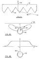
- Figure 4A is a graph of luminous intensity vs. angle for a light emitter designed to uniformly illuminate a plane surface close to the emitter. The graph is superimposed on a cross-sectional illustration of the light emitter.
- Figure 4B is a graph of surface illuminance vs. position for the light emitter of Figure 4A. The graph is superimposed on a cross-sectional illustration of the light emitter.
- Figure 1A shows a technique as disclosed in United States Patent No. 4,755,921 (Nelson) and in United States Patent No. 4,337,759 (Popovich et al).
- Light emanating in arbitrary directions 10 from light source 12 is redirected by fresnel lens 14 in such a way that the light emitted from fresnel lens 14 is substantially restricted to a single direction 16.
- fresnel lens 14 has a very low effective "f" number, due to its incorporation of a special combination of refraction and total internal reflection in the prismatic surfaces.
- fresnel lens 14 has a very low effective "f" number, due to its incorporation of a special combination of refraction and total internal reflection in the prismatic surfaces.
- the emitted light is highly directional, it is not distributed with high uniformity over the entire light emitting surface of fresnel lens 14.
- the intensity of the light output is very high at points on the light emitting surface near light source 12, and very much lower at points further from light source 12.
- Figure 1B shows another prior art approach as disclosed in United States Patent Nos. 4,984,144 and 4,989,125 (Cobb, Jr. et al).
- Light emanating in arbitrary directions from light source 20 is substantially collimated by reflector 22, which directs the light at a glancing angle a onto prismatic screen 24.
- screen 24 redirects the light in such a way that the light emitted from screen 24 is substantially restricted to a single direction 26.
- This approach can achieve higher uniformity of light distribution over the entire light emitting surface of screen 24, particularly if the light emanating from reflector 22 is very well collimated. But, in many practical situations, reflector 22 cannot collimate the light sufficiently to achieve substantially uniform light distribution over the entire light emitting surface of screen 24.
- Figure 1C shows another prior art approach as disclosed in United States Patent No. 4,799,137 (Aho) and United States Patent No. 4,874,228 (Aho et al).
- Light emanating in arbitrary directions from light source 30 is substantially collimated by reflector 32, which directs the light onto prismatic reflector 34.
- Light incident upon reflector 34 is reflected 90° away from the incident direction. Accordingly, the reflected light is substantially restricted to a single direction 36 which, within limits, is independent of the angle ⁇ at which the incident light strikes reflector 34.
- reflector 34 By carefully selecting the shape of reflector 34, one may ensure that a greater fraction of the light per unit length is incident upon reflector 34 at distances farther from light source 30 than at distances closer to light source 30, and thus attempt to overcome the intrinsic decrease in brightness as distance from source 30 increases, so as to maintain substantially uniform light distribution over the entire light emitting surface of reflector 34.
- the effectiveness of this approach also depends upon the ability of reflector 32 to collimate the light. In most practical situations reflector 32 cannot collimate the light sufficiently to achieve substantially uniform light distribution over the entire light emitting surface of reflector 34.
- FIGS 2A and 2B depict a light emitter 40 constructed in accordance with the preferred embodiment of the invention.
- Light emitter 40 takes the form of a hollow structure 42, having a length considerably greater than its minimum cross-sectional dimension.
- Reflector 44 partially collimates light emanating from light source 46 and directs the light into structure 42 in a direction approximately parallel to the longest dimension of structure 42.
- Light is emitted from structure 42 through light emitting area 48.
- substantially all of the interior surface 50 of structure 42, apart from light emitting area 48, consists of or is lined with a longitudinally specular material, as hereinafter defined.
- Light emitting area 48 has a uniform outer optical layer 52 (Figures 2A, 2B and 3).
- Outer layer 52 is designed to efficiently transmit light which is both (i) incident upon the prismatic inner surface 54 of layer 52; and, (ii) nearly parallel to the longest dimension of structure 42; such that most of the light emitted through outer layer 52 travels predominantly in a selected direction 56. More particularly, as shown in Figure 3, a light ray 58 which is nearly parallel to the longest dimension of structure 42 and incident upon inner surface 54 is subjected to both refraction and total internal reflection, resulting in the light being emitted from outer layer 52 in a restricted direction 56.
- An example of a material suitable for forming outer layer 52 is prismatic film of the type disclosed in United States Patent No. 4,984,144 (Cobb, Jr. et al). Such film can be fabricated to have the property that the emitted light is restricted to a direction substantially perpendicular to the material's emitting surface.
- Light emitting area 48 also has an inner optical layer 60, which is a partially longitudinally specular reflector and a partially longitudinally transparent light transmitter.
- the term "longitudinally specular reflector” means a material for which the z components of the unit direction vectors of the incident and reflected light rays are substantially the same, where the z direction is parallel to the surface of the material, and is also the longest direction of structure 42.
- the term “longitudinally transparent light transmitter” means a material for which the z components of the unit direction vectors of the incident and transmitted light rays are substantially the same.
- An example of a spatially variable, longitudinally specular reflective material which is also longitudinally transparent is a transparent substrate onto which a metallic film pattern is etched, such as VARALUME TM material available from TIR Systems Ltd., of Burnaby, British Columbia, Canada.
- Inner layer 60 does not have uniform longitudinal transmissivity. That is, the fractional longitudinal light transmission through inner layer 60 is not uniform over the outer surface of inner layer 60, but changes such that the intensity of the transmitted light varies in a predetermined manner as a function of position on the outer surface of inner layer 60. In many cases, it is desirable to achieve uniform light emission at all points on the outer surface of inner layer 60. Generally, to achieve such uniform emission, the transmissivity of inner layer 60 is reduced at points on inner layer 60 near light source 46 (where the incident light is brightest), and increased at points further away from light source 46 (where the incident light is dimmer). Because the reflectivity of inner layer 60 is longitudinally specular, light reflected by inner layer 60 remains collimated. Because the transmissivity through inner layer 60 is longitudinally transparent, light transmitted through inner layer 60 also remains collimated. Outer layer 52 is thus able to direct such transmitted light in the desired direction 56, as described above.
- Light emitting area 48 is not necessarily flat. If the light emitting area is curved, directional control of light emission as a function of position also facilitates directional control of the total luminous intensity of structure 42 as a function of angle.
- Figure 4A illustrates this capability in relation to a light emitter 62 having a curved light emitting area 64 designed to uniformly illuminate a plane surface 66 close to emitter 62. This is representative of indirect ceiling lighting applications.
- Superimposed on Figure 4A is a polar coordinate graph in which the luminous intensity of light emitted through area 64 is plotted as the ordinate, versus the angle ⁇ at which light is emitted from light emitting area 64.
- Figure 4B superimposes a graph of illuminance on surface 66 versus position on that surface.
- the inner and outer portions of light emitting area 64 may be suitably configured so that the intensity of the emitted light is lower at smaller incident angles and increases at larger angles.
- Figure 4B shows that the intensity of the resultant illumination is substantially uniform at all points on surface 66, irrespective of the distance between emitter 62 and any particular point on surface 66. Such uniform illumination can be attained if the inner and outer layers of light emitting area 64 are configured so that the total luminous intensity of the emitted light varies as 1/cos ⁇ over a substantial angular range.
- Reflective film of the type disclosed in United States Patent No. 4,799,137 has been used in light redirecting structures, as discussed in United States Patent No. 4,984,144 (Cobb, Jr. et al).
- the reflective film material occupies a substantial portion of the cross-sectional area of the structure, as is often necessary to achieve a large light emitting area, the structure cannot transmit light well because its interior surfaces are unable to provide sufficient longitudinally specular reflectivity.
- such structures emit light in a poorly controlled fashion, with relatively high intensity light being emitted at points on the light emitting surface near the light source, and relatively low intensity light being emitted at points farther from the light source.
- high aspect ratio light emitters constructed in accordance with the invention have the additional property of emitting highly directional light.
- the direction of light emission may be varied to suit the particular application.
- high directionality is a desired feature of linear navigational beacons, certain backlit liquid crystal displays, and certain vehicle signal lights.
- the invention also facilitates the use of a single, readily accessible light source (or a small number of such sources).
Abstract
Description
- This application pertains to light distribution from a single source into a comparatively large structure which redirects the light so that it is emitted from the structure in a restricted direction through a large emitting area in such a manner that an observer perceives uniform light distribution over the entire emitting area.
- A high aspect ratio light distribution structure is one in which the size of the structure's light emitting area is large compared to a characteristic cross-sectional width of the structure. Such structures commonly have a single localized light source.
- Examples of this concept are light guiding systems based on prism light guide material as described in United States Patent Nos. 4,260,220; 4,615,579; and, 4,787,708 (Whitehead); or, metallic light guides as described in United States Patent No. 4,105,293 (Aizenberg et al). Such prior art light guides have predominantly reflective interior surfaces. Accordingly, light rays entering one end of the guide are reflected by the guide's inner walls as the rays proceed to the other end of the guide. Such prior art light guides are designed to "leak" light in a controlled manner, such that the amount of light emitted from the guide per unit length is acceptably uniform along the entire length of the guide.
- According to International patent application WO 90/04132, on the other hand, an arrangement and method for providing an elongated light source is described which includes emitting light from an exterior light source into an inner tube having a light-transmissive opening along its length, with a diffusing medium opposite such opening and, optionally, a reflector at one end of the inner tube.
- Although such prior art light guides are very useful for general light distribution purposes, they do not perform well in situations in which it is desirable to have light emitted within a narrowly restricted range of angles from a large light emitting area, while maintaining highly uniform light distribution over the entire light emitting area. Examples of situations in which such characteristics are desirable include linear navigational beacons, which preferably emit maximum light intensity in a substantially horizontal direction; certain backlit liquid crystal displays, which preferably emit light only within a desirec range of viewing angles; and, certain vehicle signal lights, which preferably emit maximum light intensity only in desired directions. In each situation it is necessary to efficiently restrict the emitted light to a desirec direction, while maintaining highly uniform light distribution over the entire light emitting surface. The present invention satisfies these requirements and thus facilitate the construction of highly directional, highly uniform high aspect ratio light emitters.
- In accordance with the preferred embodiment, the invention provides a hollow light emitter having a length considerably greater than its minimum cross-sectional dimension for receiving light from a partially collimated light source and emitting said light from a light emitting area of said emitter in one or more selected directions with substantially uniform light output per unit length along said light emitting area, said light emitter comprising a longitudinally specularly reflective internal surface, characterized in that the light emitting area comprises:
- (i) in addition to said internal surface, an inner portion which is:
- (1) substantially longitudinally specularly reflective; and,
- (2) longitudinally transmissive, whereby most of said light is emitted in said selected directions without substantial loss of collimation;
- (ii) a refractive, prismatic outer portion positioned adjacent to, but not in optical contact with, said inner portion.
- The degree of longitudinal transmissivity of the inner portion is varied as a selected function of position on the inner portion to control the distribution of emitted light. The transmissivity variation is such that the quantity of light per unit area transmitted by the inner portion has a predetermined distribution of values as a function of position on the outer surface of the inner portion. Advantageously, the distribution of values may be substantially uniform.
- If the light emitting area is curved, then the angular distribution of the emitted light will be different at different locations. Accordingly, the transmissivity may be varied to yield a predetermined variation of total luminous intensity as a function of the direction of the emitted light. Again, the transmissivity variation may be such that the distribution of values is substantially uniform, or it may have some other useful distribution. For example, the distribution in which the total luminous intensity of the emitted light varies as 1/cosθ may be used to attain uniform illumination of a plane surface in an indirect ceiling lighting application. As another example, the distribution in which the total luminous intensity of the emitted light is substantially uniform within a selected range of the angle θ, and substantially zero outside that range, may be used to confine the effective illumination of a navigational beacon to a selected angular range.
- In many applications, the prismatic outer portion of the light emitting area can be configured such that light incident at any particular point on the inside surface of the outer portion is redirected into a direction substantially perpendicular to the outer portion at the particular point.
- Figures 1A, 1B and 1C illustrate prior art techniques for distributing light from a single source within a comparatively large structure which redirects the light so that it escapes in a restricted direction through a large emitting area.
- Figure 2A is a partially fragmented pictorial illustration of a light emitter constructed in accordance with the preferred embodiment of the invention.
- Figure 2B is a cross-section illustration taken with respect to line B-B of Figure 2A.
- Figure 3 is an enlarged cross-sectional illustration of the outer optical layer of the light emitting surface of the light emitter of Figures 2A and 2B, showing light emission in a restricted direction substantially perpendicular to the light emitting surface.
- Figure 4A is a graph of luminous intensity vs. angle for a light emitter designed to uniformly illuminate a plane surface close to the emitter. The graph is superimposed on a cross-sectional illustration of the light emitter.
- Figure 4B is a graph of surface illuminance vs. position for the light emitter of Figure 4A. The graph is superimposed on a cross-sectional illustration of the light emitter.
- Various prior art attempts have been made to construct high aspect ratio light emitters capable of distributing light from a single source in such a manner that light is emitted in a restricted direction over a large light emitting area. For example, Figure 1A shows a technique as disclosed in United States Patent No. 4,755,921 (Nelson) and in United States Patent No. 4,337,759 (Popovich et al). Light emanating in
arbitrary directions 10 fromlight source 12 is redirected byfresnel lens 14 in such a way that the light emitted fromfresnel lens 14 is substantially restricted to asingle direction 16. The technique facilitates construction of high aspect ratio light emitters becausefresnel lens 14 has a very low effective "f" number, due to its incorporation of a special combination of refraction and total internal reflection in the prismatic surfaces. Unfortunately, although the emitted light is highly directional, it is not distributed with high uniformity over the entire light emitting surface offresnel lens 14. In particular, the intensity of the light output is very high at points on the light emitting surface nearlight source 12, and very much lower at points further fromlight source 12. - Figure 1B shows another prior art approach as disclosed in United States Patent Nos. 4,984,144 and 4,989,125 (Cobb, Jr. et al). Light emanating in arbitrary directions from
light source 20 is substantially collimated byreflector 22, which directs the light at a glancing angle a ontoprismatic screen 24. Using a combination of refraction and total internal reflection,screen 24 redirects the light in such a way that the light emitted fromscreen 24 is substantially restricted to asingle direction 26. This approach can achieve higher uniformity of light distribution over the entire light emitting surface ofscreen 24, particularly if the light emanating fromreflector 22 is very well collimated. But, in many practical situations,reflector 22 cannot collimate the light sufficiently to achieve substantially uniform light distribution over the entire light emitting surface ofscreen 24. - Figure 1C shows another prior art approach as disclosed in United States Patent No. 4,799,137 (Aho) and United States Patent No. 4,874,228 (Aho et al). Light emanating in arbitrary directions from light source 30 is substantially collimated by
reflector 32, which directs the light ontoprismatic reflector 34. Light incident uponreflector 34 is reflected 90° away from the incident direction. Accordingly, the reflected light is substantially restricted to asingle direction 36 which, within limits, is independent of the angle β at which the incident light strikesreflector 34. By carefully selecting the shape ofreflector 34, one may ensure that a greater fraction of the light per unit length is incident uponreflector 34 at distances farther from light source 30 than at distances closer to light source 30, and thus attempt to overcome the intrinsic decrease in brightness as distance from source 30 increases, so as to maintain substantially uniform light distribution over the entire light emitting surface ofreflector 34. However, the effectiveness of this approach also depends upon the ability ofreflector 32 to collimate the light. In mostpractical situations reflector 32 cannot collimate the light sufficiently to achieve substantially uniform light distribution over the entire light emitting surface ofreflector 34. - Figures 2A and 2B depict a
light emitter 40 constructed in accordance with the preferred embodiment of the invention.Light emitter 40 takes the form of ahollow structure 42, having a length considerably greater than its minimum cross-sectional dimension.Reflector 44 partially collimates light emanating fromlight source 46 and directs the light intostructure 42 in a direction approximately parallel to the longest dimension ofstructure 42. Light is emitted fromstructure 42 throughlight emitting area 48. substantially all of theinterior surface 50 ofstructure 42, apart from light emittingarea 48, consists of or is lined with a longitudinally specular material, as hereinafter defined. -
Light emitting area 48 has a uniform outer optical layer 52 (Figures 2A, 2B and 3).Outer layer 52 is designed to efficiently transmit light which is both (i) incident upon the prismaticinner surface 54 oflayer 52; and, (ii) nearly parallel to the longest dimension ofstructure 42; such that most of the light emitted throughouter layer 52 travels predominantly in a selecteddirection 56. More particularly, as shown in Figure 3, alight ray 58 which is nearly parallel to the longest dimension ofstructure 42 and incident uponinner surface 54 is subjected to both refraction and total internal reflection, resulting in the light being emitted fromouter layer 52 in arestricted direction 56. An example of a material suitable for formingouter layer 52 is prismatic film of the type disclosed in United States Patent No. 4,984,144 (Cobb, Jr. et al). Such film can be fabricated to have the property that the emitted light is restricted to a direction substantially perpendicular to the material's emitting surface. -
Light emitting area 48 also has an inneroptical layer 60, which is a partially longitudinally specular reflector and a partially longitudinally transparent light transmitter. As used herein, the term "longitudinally specular reflector" means a material for which the z components of the unit direction vectors of the incident and reflected light rays are substantially the same, where the z direction is parallel to the surface of the material, and is also the longest direction ofstructure 42. Similarly, the term "longitudinally transparent light transmitter" means a material for which the z components of the unit direction vectors of the incident and transmitted light rays are substantially the same. An example of a spatially variable, longitudinally specular reflective material which is also longitudinally transparent is a transparent substrate onto which a metallic film pattern is etched, such as VARALUME™ material available from TIR Systems Ltd., of Burnaby, British Columbia, Canada. -
Inner layer 60 does not have uniform longitudinal transmissivity. That is, the fractional longitudinal light transmission throughinner layer 60 is not uniform over the outer surface ofinner layer 60, but changes such that the intensity of the transmitted light varies in a predetermined manner as a function of position on the outer surface ofinner layer 60. In many cases, it is desirable to achieve uniform light emission at all points on the outer surface ofinner layer 60. Generally, to achieve such uniform emission, the transmissivity ofinner layer 60 is reduced at points oninner layer 60 near light source 46 (where the incident light is brightest), and increased at points further away from light source 46 (where the incident light is dimmer). Because the reflectivity ofinner layer 60 is longitudinally specular, light reflected byinner layer 60 remains collimated. Because the transmissivity throughinner layer 60 is longitudinally transparent, light transmitted throughinner layer 60 also remains collimated.Outer layer 52 is thus able to direct such transmitted light in the desireddirection 56, as described above. -
Light emitting area 48 is not necessarily flat. If the light emitting area is curved, directional control of light emission as a function of position also facilitates directional control of the total luminous intensity ofstructure 42 as a function of angle. Figure 4A illustrates this capability in relation to alight emitter 62 having a curvedlight emitting area 64 designed to uniformly illuminate aplane surface 66 close toemitter 62. This is representative of indirect ceiling lighting applications. Superimposed on Figure 4A is a polar coordinate graph in which the luminous intensity of light emitted througharea 64 is plotted as the ordinate, versus the angle θ at which light is emitted from light emittingarea 64. Figure 4B superimposes a graph of illuminance onsurface 66 versus position on that surface. - As Figure 4A illustrates, the inner and outer portions of light emitting
area 64 may be suitably configured so that the intensity of the emitted light is lower at smaller incident angles and increases at larger angles. Figure 4B shows that the intensity of the resultant illumination is substantially uniform at all points onsurface 66, irrespective of the distance betweenemitter 62 and any particular point onsurface 66. Such uniform illumination can be attained if the inner and outer layers of light emittingarea 64 are configured so that the total luminous intensity of the emitted light varies as 1/cosθ over a substantial angular range. - Reflective film of the type disclosed in United States Patent No. 4,799,137 (Aho) has been used in light redirecting structures, as discussed in United States Patent No. 4,984,144 (Cobb, Jr. et al). However, if the reflective film material occupies a substantial portion of the cross-sectional area of the structure, as is often necessary to achieve a large light emitting area, the structure cannot transmit light well because its interior surfaces are unable to provide sufficient longitudinally specular reflectivity. Without the present invention, such structures emit light in a poorly controlled fashion, with relatively high intensity light being emitted at points on the light emitting surface near the light source, and relatively low intensity light being emitted at points farther from the light source.
- Generally, there are many uses for distributed light; that is, light which is emitted uniformly from long and/or wide, high aspect ratio structures. Besides having the desirable property of uniform light emission, high aspect ratio light emitters constructed in accordance with the invention have the additional property of emitting highly directional light. The direction of light emission may be varied to suit the particular application. As mentioned above, high directionality is a desired feature of linear navigational beacons, certain backlit liquid crystal displays, and certain vehicle signal lights. The invention also facilitates the use of a single, readily accessible light source (or a small number of such sources).
- As will be apparent to those skilled in the art in the light of the foregoing disclosure, many alterations and modifications are possible in the practice of this invention without departing from the scope thereof. The scope of the invention is to be construed in accordance with the substance defined by the following claims.
Claims (13)
- A hollow light emitter (40) having a length considerably greater than its minimum cross-sectional dimension for receiving light from a partially collimated light source (46) and emitting said light from a light emitting area (48) of said emitter (40) in one or more selected directions (56) with substantially uniform light output per unit length along said light emitting area (48), said light emitter (40) comprising a longitudinally specularly reflective internal surface (50), characterized in that the light emitting area (48) comprises:(i) in addition to said internal surface (50), an inner portion (60) which is:(1) substantially longitudinally specularly reflective; and,(2) longitudinally transmissive, whereby most of said light is emitted in said selected directions (56) without substantial loss of collimation;(ii) a refractive, prismatic outer portion (52) positioned adjacent to, but not in optical contact with, said inner portion (60).
- A light emitter as defined in claim 1, wherein the degree of longitudinal transmissivity of said inner portion (60) varies as a selected function of position on said inner portion (60).
- A light emitter as defined in claim 2, wherein said transmissivity varies such that the quantity of light per unit area transmitted by said inner portion (60) has a predetermined distribution of values as a function of position on the outer surface of said inner portion (60).
- A light emitter as defined in claim 3, wherein said quantity of light per unit area transmitted by said inner portion (60) is substantially uniform.
- A light emitter as defined in claim 2, wherein said light emitting area (48) is curved.
- A light emitter as defined in claim 5, wherein said transmissivity varies such that the total luminous intensity of said emitted light has a predetermined distribution of values as a function of the direction of emission of said light.
- A light emitter as defined in claim 6, wherein said total luminous intensity of said emitted light is substantially uniform.
- A light emitter as defined in claim 6, wherein said total luminous intensity of said emitted light is substantially uniform within a selected directional range, and substantially zero outside said range.
- A light emitter as defined in claim 6, wherein said transmissivity is varied such that the luminous intensity of said emitted light varies as 1/cosθ over a selected range of θ, where θ is an angle measured relative to a preselected direction of emission.
- A light emitter as defined in any one of claims 1 through 9, wherein light incident at any particular point on said outer portion (52) is redirected into a direction substantially perpendicular to said outer portion (52) at said point.
- A light emitter as defined in any one of claims 1 through 9, wherein said outer portion (52) transmits incident, collimated light in said selected direction with little or no loss of collimation.
- A light emitter as defined in any one of claims 1 through 9, wherein said outer portion (52) comprises prismatic film.
- A light emitter as defined in any one of claims 1 through 9, wherein said inner portion (60) comprises a transparent substrate bearing a metal pattern which varies as a selected function of position on said inner portion (60).
Applications Claiming Priority (3)
| Application Number | Priority Date | Filing Date | Title |
|---|---|---|---|
| US07/716,684 US5243506A (en) | 1991-06-17 | 1991-06-17 | High aspect ratio light emitter having high uniformity and directionality |
| US716684 | 1991-06-17 | ||
| PCT/CA1992/000219 WO1992022768A1 (en) | 1991-06-17 | 1992-05-26 | High aspect ratio light emitter having high uniformity and directionality |
Publications (2)
| Publication Number | Publication Date |
|---|---|
| EP0593499A1 EP0593499A1 (en) | 1994-04-27 |
| EP0593499B1 true EP0593499B1 (en) | 1996-04-10 |
Family
ID=24879006
Family Applications (1)
| Application Number | Title | Priority Date | Filing Date |
|---|---|---|---|
| EP92910555A Expired - Lifetime EP0593499B1 (en) | 1991-06-17 | 1992-05-26 | High aspect ratio light emitter having high uniformity and directionality |
Country Status (10)
| Country | Link |
|---|---|
| US (1) | US5243506A (en) |
| EP (1) | EP0593499B1 (en) |
| JP (1) | JP2711481B2 (en) |
| AU (1) | AU1785792A (en) |
| CA (1) | CA2111437C (en) |
| DE (1) | DE69209838T2 (en) |
| DK (1) | DK0593499T3 (en) |
| FI (1) | FI935681A (en) |
| NO (1) | NO303990B1 (en) |
| WO (1) | WO1992022768A1 (en) |
Families Citing this family (34)
| Publication number | Priority date | Publication date | Assignee | Title |
|---|---|---|---|---|
| CA2097109C (en) * | 1992-06-01 | 2000-01-11 | Shozo Kokawa | Liquid crystal display |
| US6712481B2 (en) | 1995-06-27 | 2004-03-30 | Solid State Opto Limited | Light emitting panel assemblies |
| US5613751A (en) | 1995-06-27 | 1997-03-25 | Lumitex, Inc. | Light emitting panel assemblies |
| US5692822A (en) * | 1995-11-29 | 1997-12-02 | Minnesota Mining & Manufacturing Co. | Uniform bi-directional dependent line light source via controlled partial reflection |
| ZA9610900B (en) * | 1995-12-27 | 1997-06-27 | Kevin D Miekis | Supporting structure for a prism light guide |
| US5661839A (en) * | 1996-03-22 | 1997-08-26 | The University Of British Columbia | Light guide employing multilayer optical film |
| US5832164A (en) * | 1996-05-24 | 1998-11-03 | Miekis; Kevin D. | Supporting structure for a prism light guide |
| GB2319877B (en) * | 1996-11-29 | 2000-07-26 | Principle Systems Limited | Illuminated sign |
| US6031958A (en) * | 1997-05-21 | 2000-02-29 | Mcgaffigan; Thomas H. | Optical light pipes with laser light appearance |
| US6079844A (en) * | 1997-06-10 | 2000-06-27 | The University Of British Columbia | High efficiency high intensity backlighting of graphic displays |
| US6024462A (en) * | 1997-06-10 | 2000-02-15 | The University Of British Columbia | High efficiency high intensity backlighting of graphic displays |
| US5901266A (en) * | 1997-09-04 | 1999-05-04 | The University Of British Columbia | Uniform light extraction from light guide, independently of light guide length |
| IT1295414B1 (en) * | 1997-10-06 | 1999-05-12 | Da Ma S R L | LINEAR LIGHTING DEVICE WITH INTERNALLY PRISMATIZED COEXTRUDED SCREENS |
| DE19851633A1 (en) * | 1998-11-10 | 2000-05-18 | Tobias Hobert | Device for forwarding and distributing electromagnetic radiation, in particular visible light |
| DE19924133A1 (en) * | 1999-05-26 | 2000-11-30 | Basler Ag | Lamp for producing a line of light with a specifiable intensity distribution along its length comprises reflectors whose position and/or surface curvature is adjustable relative to the light sources of the lamp |
| IL152459A (en) | 2000-04-25 | 2005-12-18 | Honeywell Int Inc | Hollow cavity light guide for the distribution of collimated light to a liquid crystal display |
| US6481882B1 (en) * | 2000-05-04 | 2002-11-19 | 3M Innovative Properties Company | Light pipe fixture with internal extractor |
| US6809892B2 (en) * | 2000-07-26 | 2004-10-26 | 3M Innovative Properties Company | Hollow surface illuminator |
| US6783269B2 (en) * | 2000-12-27 | 2004-08-31 | Koninklijke Philips Electronics N.V. | Side-emitting rod for use with an LED-based light engine |
| US7384173B2 (en) * | 2004-12-30 | 2008-06-10 | 3M Innovative Properties Company | Brightness enhancement article |
| US7591094B2 (en) * | 2005-05-31 | 2009-09-22 | The University Of British Columbia | Perforated multi-layer optical film luminaire |
| JP5257654B2 (en) * | 2008-03-24 | 2013-08-07 | 富士ゼロックス株式会社 | Light irradiation body, image forming structure, and image forming apparatus |
| US8224207B2 (en) | 2007-10-12 | 2012-07-17 | Fuji Xerox Co., Ltd. | Light irradiation element, image forming structure, and image forming apparatus |
| US8066405B2 (en) * | 2007-10-25 | 2011-11-29 | Simon Jerome H | Lumenairs having structurally and electrically integrated arrangements of quasi point light sources, such as LEDs |
| US8462292B2 (en) * | 2008-07-31 | 2013-06-11 | Rambus Delaware Llc | Optically transmissive substrates and light emitting assemblies and methods of making same, and methods of displaying images using the optically transmissive substrates and light emitting assemblies |
| US9657907B2 (en) * | 2010-12-14 | 2017-05-23 | Bridgelux Inc. | Side light LED troffer tube |
| WO2014070495A1 (en) | 2012-10-30 | 2014-05-08 | 3M Innovative Properties Company | Curved light duct extraction |
| US9476554B2 (en) | 2012-10-30 | 2016-10-25 | 3M Innovative Properties Company | Rectangular light duct extraction |
| US9733414B2 (en) | 2013-02-08 | 2017-08-15 | Quarkstar Llc | Illumination system based on active and passive illumination devices |
| EP3017242A1 (en) * | 2013-05-31 | 2016-05-11 | 3M Innovative Properties Company of 3M Center | Luminaire for crosswalk |
| US10302275B2 (en) | 2013-06-19 | 2019-05-28 | Bright View Technologies Corporation | Microstructure-based diffusers for creating batwing lighting patterns |
| US10072816B2 (en) | 2013-06-19 | 2018-09-11 | Bright View Technologies Corporation | Microstructure-based optical diffusers for creating batwing and other lighting patterns |
| EP3014173A4 (en) | 2013-07-26 | 2017-01-11 | Bright View Technologies Corporation | Shaped microstructure-based optical diffusers |
| US20160327241A1 (en) * | 2015-05-04 | 2016-11-10 | 3M Innovative Properties Company | Luminaire assembly |
Family Cites Families (24)
| Publication number | Priority date | Publication date | Assignee | Title |
|---|---|---|---|---|
| GB713529A (en) * | 1951-03-16 | 1954-08-11 | Edward Wasteneys Hall | Improvements in or relating to lights for vehicles and devices for preventing dazzletherefrom and assisting in the penetration of fog |
| US4105293A (en) * | 1976-08-25 | 1978-08-08 | Aizenberg Julian Borisovich | Lighting installation based on light guide |
| US4260220A (en) * | 1979-06-15 | 1981-04-07 | Canadian Patents And Development Limited | Prism light guide having surfaces which are in octature |
| US4337759A (en) * | 1979-10-10 | 1982-07-06 | John M. Popovich | Radiant energy concentration by optical total internal reflection |
| US4335421A (en) * | 1980-03-17 | 1982-06-15 | Modia Joseph W | Light fixture, light aperture and method of uniformly illuminating an optically diffusive viewing area |
| US4615579A (en) * | 1983-08-29 | 1986-10-07 | Canadian Patents & Development Ltd. | Prism light guide luminaire |
| EP0167721B1 (en) * | 1984-07-02 | 1989-10-11 | Mitsubishi Rayon Co., Ltd. | Light diffuser |
| US4805984A (en) * | 1985-11-21 | 1989-02-21 | Minnesota Mining And Manufacturing Company | Totally internally reflecting light conduit |
| CA1279783C (en) * | 1985-11-21 | 1991-02-05 | Minnesota Mining And Manufacturing Company | Totally internally reflecting thin, flexible film |
| US4755921A (en) * | 1986-04-02 | 1988-07-05 | Minnesota Mining And Manufacturing Company | Lens |
| GB2196100B (en) * | 1986-10-01 | 1990-07-04 | Mitsubishi Rayon Co | Light diffusing device |
| US4850665A (en) * | 1987-02-20 | 1989-07-25 | Minnesota Mining And Manufacturing Company | Method and apparatus for controlled emission of light from prism light guide |
| US4874228A (en) * | 1987-03-24 | 1989-10-17 | Minnesota Mining And Manufacturing Company | Back-lit display |
| US4799137A (en) * | 1987-03-24 | 1989-01-17 | Minnesota Mining And Manufacturing Company | Reflective film |
| US4834495A (en) * | 1987-05-08 | 1989-05-30 | Minnesota Mining And Manufacturing Company | Collapsible light pipe |
| US4984144A (en) * | 1987-05-08 | 1991-01-08 | Minnesota Mining And Manufacturing Company | High aspect ratio light fixture and film for use therein |
| US4787708A (en) * | 1987-05-08 | 1988-11-29 | Tir Systems Ltd. | Apparatus for continuously controlled emission of light from prism light guide |
| US4791540A (en) * | 1987-05-26 | 1988-12-13 | Minnesota Mining And Manufacturing Company | Light fixture providing normalized output |
| US4937716A (en) * | 1988-05-05 | 1990-06-26 | Tir Systems Ltd | Illuminating device having non-absorptive variable transmissivity cover |
| US4989125A (en) * | 1988-05-10 | 1991-01-29 | Minnesota Mining And Manufacturing Company | Reflector using fresnel-type structures having a plurality of active faces |
| WO1990004132A1 (en) * | 1988-10-07 | 1990-04-19 | Gulton Industries, Inc. | Illuminating system |
| US4996632A (en) * | 1988-10-07 | 1991-02-26 | Gulton Industries, Inc. | Multi-color illuminating system |
| US5054885A (en) * | 1988-10-11 | 1991-10-08 | Minnesota Mining And Manfuacturing Company | Light fixture including a partially collimated beam of light and reflective prisms having peaks lying on a curved surface |
| US5043850A (en) * | 1990-01-10 | 1991-08-27 | Minnesota Mining And Manufacturing Company | Direction dependent line light source |
-
1991
- 1991-06-17 US US07/716,684 patent/US5243506A/en not_active Expired - Lifetime
-
1992
- 1992-05-26 CA CA002111437A patent/CA2111437C/en not_active Expired - Lifetime
- 1992-05-26 DK DK92910555.9T patent/DK0593499T3/en active
- 1992-05-26 DE DE69209838T patent/DE69209838T2/en not_active Expired - Lifetime
- 1992-05-26 WO PCT/CA1992/000219 patent/WO1992022768A1/en active IP Right Grant
- 1992-05-26 JP JP4510354A patent/JP2711481B2/en not_active Expired - Fee Related
- 1992-05-26 AU AU17857/92A patent/AU1785792A/en not_active Abandoned
- 1992-05-26 EP EP92910555A patent/EP0593499B1/en not_active Expired - Lifetime
-
1993
- 1993-12-16 FI FI935681A patent/FI935681A/en unknown
- 1993-12-16 NO NO934663A patent/NO303990B1/en not_active Application Discontinuation
Also Published As
| Publication number | Publication date |
|---|---|
| NO934663L (en) | 1993-12-17 |
| DE69209838D1 (en) | 1996-05-15 |
| FI935681A0 (en) | 1993-12-16 |
| DE69209838T2 (en) | 1996-11-28 |
| US5243506A (en) | 1993-09-07 |
| JP2711481B2 (en) | 1998-02-10 |
| FI935681A (en) | 1994-02-14 |
| JPH06507996A (en) | 1994-09-08 |
| AU1785792A (en) | 1993-01-12 |
| NO303990B1 (en) | 1998-10-05 |
| EP0593499A1 (en) | 1994-04-27 |
| CA2111437C (en) | 1995-07-18 |
| NO934663D0 (en) | 1993-12-16 |
| WO1992022768A1 (en) | 1992-12-23 |
| CA2111437A1 (en) | 1992-12-23 |
| DK0593499T3 (en) | 1996-05-06 |
Similar Documents
| Publication | Publication Date | Title |
|---|---|---|
| EP0593499B1 (en) | High aspect ratio light emitter having high uniformity and directionality | |
| US4750798A (en) | Prism light guide luminaire | |
| US4615579A (en) | Prism light guide luminaire | |
| US5309544A (en) | Light pipe having optimized cross-section | |
| US6185357B1 (en) | Illumination system using edge-illuminated hollow waveguide and lenticular optical structures | |
| US5054885A (en) | Light fixture including a partially collimated beam of light and reflective prisms having peaks lying on a curved surface | |
| KR100474233B1 (en) | Optical sight optical structure | |
| CA2122819C (en) | Lighting structure having variable transmissivity internal light guide illumination | |
| EP0694146B1 (en) | Line light source | |
| JP2000011723A (en) | Sheet-like lighting system | |
| KR20020091255A (en) | Light pipe fixture with internal extractor | |
| JP2004185036A (en) | Backlighting used for display | |
| JP2001035230A (en) | Flat lighting system | |
| US20040114371A1 (en) | Luminaire comprising an elongate light source and a back reflector | |
| WO2009087587A1 (en) | Lighting system | |
| US20220034463A1 (en) | Multi-beam vehicle light | |
| US5692822A (en) | Uniform bi-directional dependent line light source via controlled partial reflection | |
| US5117478A (en) | Device for redirecting light through a hollow tubular light conduit | |
| CA1321988C (en) | Light fixture | |
| US5671306A (en) | Lighting structure for intensely illuminating narrow linear region | |
| EP1350061A2 (en) | Luminaire comprising an elongate light source and a back reflector | |
| KR100463934B1 (en) | Back-coupled lighting system to regenerate light | |
| KR19980023990A (en) | Lighting system | |
| JPH07107567B2 (en) | Surface lighting device | |
| MXPA97005276A (en) | Light directing optical structure |
Legal Events
| Date | Code | Title | Description |
|---|---|---|---|
| PUAI | Public reference made under article 153(3) epc to a published international application that has entered the european phase |
Free format text: ORIGINAL CODE: 0009012 |
|
| 17P | Request for examination filed |
Effective date: 19940103 |
|
| AK | Designated contracting states |
Kind code of ref document: A1 Designated state(s): DE DK ES FR GB IT SE |
|
| 17Q | First examination report despatched |
Effective date: 19940616 |
|
| RAP1 | Party data changed (applicant data changed or rights of an application transferred) |
Owner name: MINNESOTA MINING AND MANUFACTURING COMPANY |
|
| GRAH | Despatch of communication of intention to grant a patent |
Free format text: ORIGINAL CODE: EPIDOS IGRA |
|
| GRAA | (expected) grant |
Free format text: ORIGINAL CODE: 0009210 |
|
| AK | Designated contracting states |
Kind code of ref document: B1 Designated state(s): DE DK ES FR GB IT SE |
|
| PG25 | Lapsed in a contracting state [announced via postgrant information from national office to epo] |
Ref country code: ES Free format text: THE PATENT HAS BEEN ANNULLED BY A DECISION OF A NATIONAL AUTHORITY Effective date: 19960410 |
|
| REG | Reference to a national code |
Ref country code: DK Ref legal event code: T3 |
|
| ITF | It: translation for a ep patent filed |
Owner name: PORTA CHECCACCI E BOTTI S.R.L. |
|
| REF | Corresponds to: |
Ref document number: 69209838 Country of ref document: DE Date of ref document: 19960515 |
|
| ET | Fr: translation filed | ||
| PG25 | Lapsed in a contracting state [announced via postgrant information from national office to epo] |
Ref country code: SE Effective date: 19960710 |
|
| PLBE | No opposition filed within time limit |
Free format text: ORIGINAL CODE: 0009261 |
|
| STAA | Information on the status of an ep patent application or granted ep patent |
Free format text: STATUS: NO OPPOSITION FILED WITHIN TIME LIMIT |
|
| 26N | No opposition filed | ||
| PGFP | Annual fee paid to national office [announced via postgrant information from national office to epo] |
Ref country code: FR Payment date: 19980420 Year of fee payment: 7 |
|
| PGFP | Annual fee paid to national office [announced via postgrant information from national office to epo] |
Ref country code: DK Payment date: 19980422 Year of fee payment: 7 |
|
| PGFP | Annual fee paid to national office [announced via postgrant information from national office to epo] |
Ref country code: GB Payment date: 19980427 Year of fee payment: 7 |
|
| PG25 | Lapsed in a contracting state [announced via postgrant information from national office to epo] |
Ref country code: GB Free format text: LAPSE BECAUSE OF NON-PAYMENT OF DUE FEES Effective date: 19990526 |
|
| PG25 | Lapsed in a contracting state [announced via postgrant information from national office to epo] |
Ref country code: DK Free format text: LAPSE BECAUSE OF NON-PAYMENT OF DUE FEES Effective date: 19990531 |
|
| GBPC | Gb: european patent ceased through non-payment of renewal fee |
Effective date: 19990526 |
|
| PG25 | Lapsed in a contracting state [announced via postgrant information from national office to epo] |
Ref country code: FR Free format text: LAPSE BECAUSE OF NON-PAYMENT OF DUE FEES Effective date: 20000131 |
|
| REG | Reference to a national code |
Ref country code: FR Ref legal event code: ST |
|
| REG | Reference to a national code |
Ref country code: DK Ref legal event code: EBP |
|
| PG25 | Lapsed in a contracting state [announced via postgrant information from national office to epo] |
Ref country code: IT Free format text: LAPSE BECAUSE OF NON-PAYMENT OF DUE FEES;WARNING: LAPSES OF ITALIAN PATENTS WITH EFFECTIVE DATE BEFORE 2007 MAY HAVE OCCURRED AT ANY TIME BEFORE 2007. THE CORRECT EFFECTIVE DATE MAY BE DIFFERENT FROM THE ONE RECORDED. Effective date: 20050526 |
|
| PGFP | Annual fee paid to national office [announced via postgrant information from national office to epo] |
Ref country code: DE Payment date: 20100519 Year of fee payment: 19 |
|
| REG | Reference to a national code |
Ref country code: DE Ref legal event code: R119 Ref document number: 69209838 Country of ref document: DE Effective date: 20111201 |
|
| PG25 | Lapsed in a contracting state [announced via postgrant information from national office to epo] |
Ref country code: DE Free format text: LAPSE BECAUSE OF NON-PAYMENT OF DUE FEES Effective date: 20111201 |