EP0592196A2 - Noise eliminating circuits - Google Patents
Noise eliminating circuits Download PDFInfo
- Publication number
- EP0592196A2 EP0592196A2 EP19930307916 EP93307916A EP0592196A2 EP 0592196 A2 EP0592196 A2 EP 0592196A2 EP 19930307916 EP19930307916 EP 19930307916 EP 93307916 A EP93307916 A EP 93307916A EP 0592196 A2 EP0592196 A2 EP 0592196A2
- Authority
- EP
- European Patent Office
- Prior art keywords
- stationary
- image part
- filter
- noise eliminating
- input image
- Prior art date
- Legal status (The legal status is an assumption and is not a legal conclusion. Google has not performed a legal analysis and makes no representation as to the accuracy of the status listed.)
- Granted
Links
- 238000001514 detection method Methods 0.000 claims description 10
- 230000007704 transition Effects 0.000 abstract description 9
- 230000008030 elimination Effects 0.000 description 17
- 238000003379 elimination reaction Methods 0.000 description 17
- 238000010586 diagram Methods 0.000 description 13
- 230000000694 effects Effects 0.000 description 12
- 238000012935 Averaging Methods 0.000 description 3
- 206010047571 Visual impairment Diseases 0.000 description 3
- 238000003708 edge detection Methods 0.000 description 3
- 230000015556 catabolic process Effects 0.000 description 2
- 238000013144 data compression Methods 0.000 description 2
- 238000006731 degradation reaction Methods 0.000 description 2
- 125000004122 cyclic group Chemical group 0.000 description 1
- 230000000593 degrading effect Effects 0.000 description 1
- 238000001914 filtration Methods 0.000 description 1
- 230000000116 mitigating effect Effects 0.000 description 1
- 238000007781 pre-processing Methods 0.000 description 1
- 230000001603 reducing effect Effects 0.000 description 1
Images


Classifications
-
- H—ELECTRICITY
- H04—ELECTRIC COMMUNICATION TECHNIQUE
- H04N—PICTORIAL COMMUNICATION, e.g. TELEVISION
- H04N19/00—Methods or arrangements for coding, decoding, compressing or decompressing digital video signals
- H04N19/80—Details of filtering operations specially adapted for video compression, e.g. for pixel interpolation
-
- G—PHYSICS
- G06—COMPUTING; CALCULATING OR COUNTING
- G06T—IMAGE DATA PROCESSING OR GENERATION, IN GENERAL
- G06T7/00—Image analysis
- G06T7/20—Analysis of motion
-
- H—ELECTRICITY
- H04—ELECTRIC COMMUNICATION TECHNIQUE
- H04N—PICTORIAL COMMUNICATION, e.g. TELEVISION
- H04N5/00—Details of television systems
- H04N5/14—Picture signal circuitry for video frequency region
- H04N5/144—Movement detection
-
- H—ELECTRICITY
- H04—ELECTRIC COMMUNICATION TECHNIQUE
- H04N—PICTORIAL COMMUNICATION, e.g. TELEVISION
- H04N5/00—Details of television systems
- H04N5/14—Picture signal circuitry for video frequency region
- H04N5/21—Circuitry for suppressing or minimising disturbance, e.g. moiré or halo
Definitions
- This invention relates to noise eliminating circuits such as may be used for preprocessing immediately before encoding an input signal.
- an apparatus for compressing and decompressing an input image signal often has noise eliminating means immediately in front of an encoder provided in a data compression system of the apparatus.
- noise eliminating circuits used for the noise eliminating means a noise eliminating circuit based on three-dimensional processing is known.
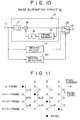
- Fig. 10 shows a block diagram of an example of the above-mentioned noise eliminating circuit.
- a terminal 11 is supplied with a digitally converted input signal (image signal) for example.
- the input signal is supplied to a noise eliminating filter for stationary image part 12 if an input image based on pixels constituting the input signal is the stationary image part and a noise eliminating filter for moving image part 13 if the input image is the moving image part.
- the filters 12 and 13 perform noise elimination processing on the input signal according to contents of the input image. Output from each of the filters is sent to a switch 20.
- the input image is also supplied to a motion detector 30 which detects a motion of the input image on a pixel basis.
- the switch 20 is adaptively operated by motion control output according to the detected motion of the input image.
- a pixel in the stationary image part is noise-eliminated by a time filter which performs filter processing relative to time and a dynamic, moving pixel is noise-eliminated through a spatial filter.
- performing noise elimination by adaptively selecting between the filters according to a movement of an input image achieves noise elimination without degrading a picture quality of the input image.
- the noise eliminating filter for stationary image 12 is a simple mean-value filter having a frame memory 15.
- a memory output value from a preceding frame is multiplied by k (0 ⁇ k ⁇ 1) in a coefficient multiplier 16 and a resulting value is added in an adder 18 to a value obtained by multiplying an input image of a current frame supplied to the input terminal 11 by (1 - k) in a coefficient multiplier 17.
- a resultant value provides a filter output.
- the noise eliminating filter for moving image part 13 is an intermediate-value filter such as a median filter, a type of a spatial filter.
- the intermediate-value filter uses a level of a pixel which is intermediate between levels of two pixels before and after a pixel in attention as a level of the pixel in attention.
- Fig. 12 describes an operation of this filter.
- noise n is introduced in pixel b in attention (an intrinsic level of the pixel is also b) for example, an intermediate value among a, n and c is selected; that is, c is selected. Since, in a next pixel, n is greater than d, the noise n is selected for the first time. Since this noise level is lower than d, even if the noise n is selected, it does not extremely stand out from pixels around it and therefore is not prominent so much.
- Fig. 13 describes detection of a motion of of an input image.
- a difference between each of 3 x 3 pixels around pixel e in attention in a current frame (nth frame) and each of the same pixel locations in a preceding frame (n - 1 frame) is obtained (a - a', b - b', ... i - i'). Then sum S of the differences is obtained.
- a value of the sum S is compared with a predetermined threshold value. If the sum S is greater than the threshold value, a pixel in attention at the time is determined to be a moving pixel (moving image part); if the sum S is smaller than the threshold value, the pixel in attention is determined to be a stationary pixel (stationary image part).
- noise of noise level a
- the noise component will not disappear several frames later. Effects of the noise will remain for long, accompanying an after-image accordingly.
- a noise eliminating circuit wherein a noise eliminating filter for moving image part to be used when an input image is the moving image part and a noise eliminating filter for stationary image part to be used when the input image is the stationary image part are adaptively switched between according to a motion of the input image; based on an output from a detector for detecting the motion of the input image, one of outputs of the above-mentioned noise eliminating filters is selected; and the above-mentioned noise eliminating filter for stationary image part outputs an input image obtained by averaging the number of input stationary continuous frames n.
- a noise eliminating circuit wherein a noise eliminating filter for moving image part to be used when an input image is the moving image part and a noise eliminating filter for stationary image part to be used when the input image is the stationary image part are adaptively selected between according to a motion of the input image; based on an output of a detector for detecting the motion of the input image, outputs of the above-mentioned noise eliminating filters are adaptively mixed to be output; and the above-mentioned noise eliminating filter for stationary image part outputs average input image information determined by the number of continuous stationary frames n in an input stationary pixel.
- a stationary counter 50 calculates the number of continuous stationary frames n in a stationary pixel (refer to Fig. 2) and, weighting factors l/n and (n-l)/n from the number of continuous stationary frames n. These weighting factors are used when the input image is the stationary image part.
- a frame memory 41 and multiplier 42 provided in the noise eliminating filter for stationary image part 40 calculate a final output signal of a previous frame on which noise averaging processing in terms of time, the processing to be determined by the number of continuous stationary frames n at a stationary pixel has been performed.
- a multiplier 43 weights an input signal of a current frame by n. Output signals of the previous and current frames are added together to be used for an output of the noise eliminating filter 40.
- n 1 at the transition point from the moving image part to the stationary image part, only a signal of the current frame is output from an adder 44, resulting in a filter output having no after-image.
- n 1 also at a transition point from the stationary image part to the moving image part, only the signal of the current frame is output from the adder 44. Consequently, a picture quality at a moving part of an image is not degraded.
- the output signal of the previous frame may be weighted by n to be output, so that an output signal with a noise suppressed is obtained.
- Embodiments of the present invention provide a noise eliminating circuit for effectively improving picture quality, especially the picture quality at a transition point between images.
- Fig. 1 shows a preferred embodiment of a noise eliminating circuit according to the invention.
- An input signal entered in a terminal 11 is supplied to the noise eliminating filter for moving image part 13 and the noise eliminating filter for stationary image part 40 at the same time.
- These filters 13 and 40 are switched between by a switch 20 and an output of a selected filter is sent to an output terminal 12.
- a conventional filter such as a median filter, one of spatial filters, may be used.
- Fig. 2 shows an example of processing of the median filter.
- noises n1 and n2 are introduced in the input signal (with a waveform p).
- Reference numeral 30 indicates a detector for detecting a motion of the input image. An embodiment of this detector will be described later. An output of this detector is sent to the switch 20 and a stationary counter 50 by which the number of continuous stationary frames n for a stationary frame is calculated.
- the stationary counter 50 calculates weighting factors l/n and (n - l)/n from this number of stationary frames n and sends the weighting factors to the filter for stationary image part 40.
- the filter for stationary image part 40 has a frame memory 41 for averaging.
- An output from the frame memory 41 (an output signal with the noise in the previous frame suppressed) is supplied to a first multiplier 42 to be multiplied by the weighting factor (n - l)/n.
- the input signal of the current frame supplied to the terminal 11 is multiplied by the weighting factor l/n in a second multiplier 43.
- These two multiplication outputs are added together in an adder 44 to be used as a final output of the filter 40.
- the output of the adder 44 is also sent to the frame memory 41.
- n 1 at such a point as the transition point from the moving image part to the stationary image part, the output of the first multiplier 42 becomes zero to cause the input signal itself to be output from the filter 40, producing no after-image.
- the embodiment is cyclically constituted to enter the output of the adder 44 into the frame memory 41, image information of the moving image part is cyclically averaged when the input image changes from moving to stationary. Consequently, as time passes, an influence of the moving image on the stationary image gets smaller, increasingly showing the noise elimination effect.
- Fig. 4 shows the embodiment of the motion detector 30.
- threshold values for motion detection are adaptively varied between an edge potion and a flat portion of an image. Consequently, the input signal is supplied to an edge detector 31.
- a Laplacian filter is used for edge detection. This Laplacian filter performs edge detection in blocks of 3 x 3 pixels including the pixel in attention set to a factor shown in Fig. 5. Corresponding input pixels are multiplied with Laplacian coefficients (-1 or 8) respectively. A sum of the multiplications is divided by 8 to provide a detection value (activity) L.
- This activity L is compared with a predetermined threshold value ⁇ .
- a threshold value ⁇ (in this embodiment, ⁇ 1 or ⁇ 2 where ⁇ 1 > ⁇ 2) for the motion detector 33 is selected.
- a coefficient ROM 32 is provided as shown in Fig. 4. This ROM stores the two threshold values ⁇ 1 and ⁇ 2. When the edge portion is detected for example, ⁇ 1, which is greater, is selected.
- a motion of the input signal is determined. That is, the motion detector 33 performs following determination processing based on the two threshold values ⁇ 1 and ⁇ 2:
- the filter for stationary image part 40 is selected.
- the filter for stationary image part 40 suppress a noise more than the filter for the moving image part 13 does, providing a higher noise elimination effect in the flat portion than the edge portion.
- the smaller ⁇ 2 is used according to the case (2), so that it is more probable that the pixel is determined to be moving rather than stationary unlike the case (1). Consequently, the noise elimination effect in the edge portion gets somewhat lower. But, since it is the edge portion, noise introduction is not so conspicuous. Therefore, using the smaller threshold value causes little influence on noise elimination.
- ⁇ 1, ⁇ 2 and ⁇ are suitably selected according to an application.
- reference values of ⁇ 1 and ⁇ 2 may be selected. Any number of threshold values can be prepared.
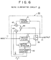
- Fig. 6 shows a variation to the embodiment of Fig. 1.
- the input to the frame memory 41 is the output itself of the adder 44.
- an output signal obtained at an output terminal 21 is used. Except it, the embodiment of Fig. 6 is the same as the embodiment of Fig. 1.
- the output signal at the output terminal 21 is an output signal with a noise in space processed by a noise eliminating filter for moving image part 13 or an output signal with a noise in time processed by a noise eliminating filter for stationary image part 40. Therefore, each of the outputs is an output of the previous frame with the noise sufficiently suppressed.
- the filter 40 comprising a first multiplier 42, a second multiplier 43, an adder 44, and a frame memory 41
- the above-mentioned output signal with the noise sufficiently suppressed is used as an input.
- An output signal of the previous frame weighted by the number of continuous stationary frames n is added to an input signal of the current frame weighted by the number of continuous stationary frames n.
- a result of the addition is used as a filter output.
- the filter output with the noise suppressed by the filter 40 can be used as an output signal, resulting in a greater noise reducing effect at the above-mentioned changing point than that of the embodiment of Fig. 1.
- Fig. 7 shows a second variation to the embodiment of Fig. 1.
- an input signal itself of the current frame is used as an input signal to the noise eliminating filter for moving image part 13.
- a filter output of a noise eliminating filter for stationary image part 40 is used as an input signal to a noise eliminating filter for moving image part 13.
- the filter output on which the noise elimination processing in terms of time has been performed is entered in the noise eliminating filter for moving image part 13, so that the noise elimination effect in the moving part is greater than that obtained by entering the input signal of the current frame for the noise processing in space.
- Fig. 8 shows a variation to the embodiment of the Fig. 7.
- a switch 60 is provided before a noise eliminating filter for moving image part 13 to adaptively switch between the input signal of the current frame and an output signal of a previous frame according to a motion.
- the input signal of the current frame is selected; in the case of the stationary image part, the output signal of the previous frame is selected.
- the noise elimination processing is performed based on the output signal of the previous frame with the noise sufficiently suppressed, providing an effective noise elimination.
- the an output of this noise elimination processing is supplied to a frame memory 41 for cyclic processing, totally providing a substantially significant noise suppressing effect.
- the filter output resulted from the noise elimination processing in time and the filter output resulted from the noise elimination processing in space are adaptively switched between according to the output of the motion detection.
- a mixer 70 is provided instead of the switch 20 as used in the above-mentioned embodiments.
- a mixing ratio in the mixer 70 is controlled according to a quantity of motion of an input image.
- X ⁇ i (k) mq x dm(k) + (1-mq) x ds(k)
- Fk an input image value at a unit pixel of 3 x 3 block in k frame
- i, j coordinates of pixel
- C constant
- adaptively controlling the mixing ratio of the outputs of both filters according to the motion of the input image improves a picture quality degradation at a transition point between the moving image part and the stationary image part.
- the mixing coefficient mq, (1 - mq) is not linearly controlled according to the motion. Rather, it may be prepared in several types, one of which being adaptively selected.
- the above-mentioned embodiments can be combined with each other in any way. Some combinations provide the noise elimination in time and space more effectively than a single embodiment does.
- a single threshold value may be used as with the previously proposed constitution.
- the embodiments of the invention described above provide a noise eliminating circuit wherein outputs of a filter in time and a filter in space are adaptively selected between according to a motion of an input signal.
- This constitution effectively suppresses a noise introduced in a moving image or a stationary image, generating an output signal with a good picture quality.
Abstract
Description
- This invention relates to noise eliminating circuits such as may be used for preprocessing immediately before encoding an input signal.
- It is known that an apparatus for compressing and decompressing an input image signal often has noise eliminating means immediately in front of an encoder provided in a data compression system of the apparatus. Of noise eliminating circuits used for the noise eliminating means, a noise eliminating circuit based on three-dimensional processing is known.
- Fig. 10 shows a block diagram of an example of the above-mentioned noise eliminating circuit. In the figure, a
terminal 11 is supplied with a digitally converted input signal (image signal) for example. The input signal is supplied to a noise eliminating filter forstationary image part 12 if an input image based on pixels constituting the input signal is the stationary image part and a noise eliminating filter for movingimage part 13 if the input image is the moving image part. Thefilters switch 20. - The input image is also supplied to a
motion detector 30 which detects a motion of the input image on a pixel basis. Theswitch 20 is adaptively operated by motion control output according to the detected motion of the input image. Thus, a pixel in the stationary image part is noise-eliminated by a time filter which performs filter processing relative to time and a dynamic, moving pixel is noise-eliminated through a spatial filter. - Thus, performing noise elimination by adaptively selecting between the filters according to a movement of an input image achieves noise elimination without degrading a picture quality of the input image.
- The noise eliminating filter for
stationary image 12 is a simple mean-value filter having aframe memory 15. In this filter, a memory output value from a preceding frame is multiplied by k (0 < k < 1) in acoefficient multiplier 16 and a resulting value is added in anadder 18 to a value obtained by multiplying an input image of a current frame supplied to theinput terminal 11 by (1 - k) in acoefficient multiplier 17. A resultant value provides a filter output. - Fig. 11 describes an operation of the
noise eliminating filter 12. If a random noise indicated by a dot is introduced in a particular pixel of each frame and k = 0.5, then noise levels a, b, c and d get smaller sequentially by the second power due to a filter effect in time of thenoise eliminating filter 12. - The noise eliminating filter for moving
image part 13 is an intermediate-value filter such as a median filter, a type of a spatial filter. The intermediate-value filter uses a level of a pixel which is intermediate between levels of two pixels before and after a pixel in attention as a level of the pixel in attention. Fig. 12 describes an operation of this filter. - For an input image variation like a curve P, if noise n is introduced in pixel b in attention (an intrinsic level of the pixel is also b) for example, an intermediate value among a, n and c is selected; that is, c is selected. Since, in a next pixel, n is greater than d, the noise n is selected for the first time. Since this noise level is lower than d, even if the noise n is selected, it does not extremely stand out from pixels around it and therefore is not prominent so much.
- In this connection, a normal output without filtering results in a pixel level of Fig. 12 and the noise n is selected when the pixel level is low, making the noise level stand out and the selected noise n prominent.
- Fig. 13 describes detection of a motion of of an input image. In the figure, a difference between each of 3 x 3 pixels around pixel e in attention in a current frame (nth frame) and each of the same pixel locations in a preceding frame (n - 1 frame) is obtained (a - a', b - b', ... i - i'). Then sum S of the differences is obtained.
- A value of the sum S is compared with a predetermined threshold value. If the sum S is greater than the threshold value, a pixel in attention at the time is determined to be a moving pixel (moving image part); if the sum S is smaller than the threshold value, the pixel in attention is determined to be a stationary pixel (stationary image part).
- However, since a noise eliminating circuit having the above-mentioned constitution uses a time filter (mean-value filter), an averaged output remains to an end.
- For example, if a noise (of noise level a) gets in a
pixel 1 of the nth frame as shown in Fig. 11, the noise component will not disappear several frames later. Effects of the noise will remain for long, accompanying an after-image accordingly. - Besides, since an influence to be given by a noise to an immediately succeeding frame is as large as 1/2, a picture quality in transition from a moving image part to a stationary image part is not improved effectively.
- According to one aspect of the invention there is provided a noise eliminating circuit wherein a noise eliminating filter for moving image part to be used when an input image is the moving image part and a noise eliminating filter for stationary image part to be used when the input image is the stationary image part are adaptively switched between according to a motion of the input image; based on an output from a detector for detecting the motion of the input image, one of outputs of the above-mentioned noise eliminating filters is selected; and the above-mentioned noise eliminating filter for stationary image part outputs an input image obtained by averaging the number of input stationary continuous frames n.
- According to another aspect of the invention there is provided a noise eliminating circuit wherein a noise eliminating filter for moving image part to be used when an input image is the moving image part and a noise eliminating filter for stationary image part to be used when the input image is the stationary image part are adaptively selected between according to a motion of the input image; based on an output of a detector for detecting the motion of the input image, outputs of the above-mentioned noise eliminating filters are adaptively mixed to be output; and the above-mentioned noise eliminating filter for stationary image part outputs average input image information determined by the number of continuous stationary frames n in an input stationary pixel.
- Respective further aspects of the invention are set forth in
claims - In a preferred embodiment of the invention shown in Fig. 1, based on motion information given by a
motion detector 30, astationary counter 50 calculates the number of continuous stationary frames n in a stationary pixel (refer to Fig. 2) and, weighting factors l/n and (n-l)/n from the number of continuous stationary frames n. These weighting factors are used when the input image is the stationary image part. - That is, a
frame memory 41 andmultiplier 42 provided in the noise eliminating filter forstationary image part 40 calculate a final output signal of a previous frame on which noise averaging processing in terms of time, the processing to be determined by the number of continuous stationary frames n at a stationary pixel has been performed. A multiplier 43 weights an input signal of a current frame by n. Output signals of the previous and current frames are added together to be used for an output of thenoise eliminating filter 40. - Thus, since n = 1 at the transition point from the moving image part to the stationary image part, only a signal of the current frame is output from an
adder 44, resulting in a filter output having no after-image. Likewise, since n = 1 also at a transition point from the stationary image part to the moving image part, only the signal of the current frame is output from theadder 44. Consequently, a picture quality at a moving part of an image is not degraded. - In other cases than mentioned above, the output signal of the previous frame may be weighted by n to be output, so that an output signal with a noise suppressed is obtained.
- Embodiments of the present invention provide a noise eliminating circuit for effectively improving picture quality, especially the picture quality at a transition point between images.
- Embodiments of the invention will now be described, by way of example, with reference to the accompanying drawings in which:
- Fig. 1 is a block diagram illustrating a noise eliminating circuit practiced as a preferred embodiment of the invention;
- Fig. 2 shows an example of processing of a median filter used as a spatial filter;
- Fig. 3 is a diagram describing the number of continuous stationary frames at particular pixels;
- Fig. 4 is a block diagram illustrating a motion detector;
- Fig. 5 is a diagram describing an example of a Laplacian filter for edge detection;
- Fig. 6 is a diagram illustrating a variation to the embodiment of Fig. 1;
- Fig. 7 is a diagram illustrating another variation to the embodiment of Fig. 1;
- Fig. 8 is a diagram illustrating a variation to the embodiment of Fig. 7;
- Fig. 9 is a diagram illustrating an embodiment of the invention wherein filter outputs are mixed rather than selected between;
- Fig. 10 is a diagram illustrating a previously proposed noise eliminating circuit;
- Fig. 11 is a diagram illustrating an operation of a filter for stationary image part;
- Fig. 12 is a diagram illustrating an operation of a filter for moving image part ; and
- Fig. 13 is a diagram describing motion detection.
- A noise eliminating circuit practiced as a preferred embodiment of this invention and as applied to a data compression system of a CODEC (Coder/Decoder) apparatus will be described in detail with reference to drawings.
- Fig. 1 shows a preferred embodiment of a noise eliminating circuit according to the invention. An input signal entered in a
terminal 11 is supplied to the noise eliminating filter for movingimage part 13 and the noise eliminating filter forstationary image part 40 at the same time. Thesefilters switch 20 and an output of a selected filter is sent to anoutput terminal 12. - For the
noise eliminating filter 13, a conventional filter such as a median filter, one of spatial filters, may be used. Fig. 2 shows an example of processing of the median filter. In this example, noises n1 and n2 are introduced in the input signal (with a waveform p). -
Reference numeral 30 indicates a detector for detecting a motion of the input image. An embodiment of this detector will be described later. An output of this detector is sent to theswitch 20 and astationary counter 50 by which the number of continuous stationary frames n for a stationary frame is calculated. - Fig. 3 describes the number of continuous stationary frames n. As shown in the figure, given M being a moving pixel and S being a stationary pixel, n is always 1 if a pixel in attention is the moving pixel; n = 1 also at a transition point from a moving image part to a stationary image part and vice versa. In the stationary image part, n is sequentially accumulated by the number of stationary frames. Fig. 3 indicates a n value obtained when the pixel in attention moves over three frames and following three frames are stationary.
- The
stationary counter 50 calculates weighting factors l/n and (n - l)/n from this number of stationary frames n and sends the weighting factors to the filter forstationary image part 40. - Referring to Fig. 1, the filter for
stationary image part 40 has aframe memory 41 for averaging. An output from the frame memory 41 (an output signal with the noise in the previous frame suppressed) is supplied to afirst multiplier 42 to be multiplied by the weighting factor (n - l)/n. The input signal of the current frame supplied to the terminal 11 is multiplied by the weighting factor l/n in asecond multiplier 43. These two multiplication outputs are added together in anadder 44 to be used as a final output of thefilter 40. The output of theadder 44 is also sent to theframe memory 41. Since the input to theframe memory 41 is:
where, Xi(k) = input data (k frame) and

memory 41,
output signal X̂i to be obtained at the terminal 21 in the stationary image part is:
where, X̂i(k) indicates the output signal with noise suppressed. - For example, in the moving image part, the
noise eliminating filter 13 is selected, so that output signal X̂(k) at the time is:
where, - med[ ] :
- median filter processing;
- Xi(k) :
- input data at current point of time;
- Xi-1(k) :
- input data immediately before; and
- Xi+1(k) :
- input data immediately after.
- As shown in Fig. 2, since the numbers of frames to be averaged by the number of continuous frames n are different, a noise elimination effect gets higher as the value n gets greater. Since n = 1 at such a point as the transition point from the moving image part to the stationary image part, the output of the
first multiplier 42 becomes zero to cause the input signal itself to be output from thefilter 40, producing no after-image. - Since the embodiment is cyclically constituted to enter the output of the
adder 44 into theframe memory 41, image information of the moving image part is cyclically averaged when the input image changes from moving to stationary. Consequently, as time passes, an influence of the moving image on the stationary image gets smaller, increasingly showing the noise elimination effect. - Fig. 4 shows the embodiment of the
motion detector 30. In motion detection in the figure, threshold values for motion detection are adaptively varied between an edge potion and a flat portion of an image. Consequently, the input signal is supplied to anedge detector 31. In this embodiment, a Laplacian filter is used for edge detection. This Laplacian filter performs edge detection in blocks of 3 x 3 pixels including the pixel in attention set to a factor shown in Fig. 5. Corresponding input pixels are multiplied with Laplacian coefficients (-1 or 8) respectively. A sum of the multiplications is divided by 8 to provide a detection value (activity) L. - Referring to a 3 x 3 block (the nth frame) shown in Fig. 13, if pixels a through i are input levels, then the activity L is:

- This activity L is compared with a predetermined threshold value β.
- If L ≧ β, then the edge portion; if L < β, then the flat portion. Based on a comparison output CA obtained by this determination, a threshold value α (in this embodiment, α1 or α2 where α1 > α2) for the
motion detector 33 is selected. - In this embodiment, a
coefficient ROM 32 is provided as shown in Fig. 4. This ROM stores the two threshold values α1 and α2. When the edge portion is detected for example, α1, which is greater, is selected. - Based on the threshold value α selected by the comparison output CA, a motion of the input signal is determined. That is, the
motion detector 33 performs following determination processing based on the two threshold values α1 and α2: - (1) L < β (the flat portion)
S ≧ α1 ... the moving image part; and
S < α1 ... the stationary image part. - (2) L ≧ β (the edge portion)
S ≧ α2 ... the moving part; and
S < α2 ... the stationary part. - According to the case (1), it is more probable that the pixel is determined to be the stationary image part rather than the moving image part. Consequently, the filter for
stationary image part 40 is selected. The filter forstationary image part 40 suppress a noise more than the filter for the movingimage part 13 does, providing a higher noise elimination effect in the flat portion than the edge portion. - In the edge portion, the smaller α2 is used according to the case (2), so that it is more probable that the pixel is determined to be moving rather than stationary unlike the case (1). Consequently, the noise elimination effect in the edge portion gets somewhat lower. But, since it is the edge portion, noise introduction is not so conspicuous. Therefore, using the smaller threshold value causes little influence on noise elimination.
- Rather, using the filter for
stationary image part 40 in the edge portion blurs the image because the filter is a time filter. In the above-mentioned constitution, it is more probable that the pixel is determined to be moving in the edge portion, so that the noise eliminating filter forstationary image part 40 is selected less often, posing no risk of blurring the image. - Thus, adaptively changing the threshold values for motion detection based on the edge information enhances the noise elimination effect in the flat portion, mitigating a picture quality degradation in the edge portion. Values for the above-mentioned α1, α2 and β are suitably selected according to an application. Instead of the
ROM 32, reference values of α1 and α2 may be selected. Any number of threshold values can be prepared. - Fig. 6 shows a variation to the embodiment of Fig. 1. In the embodiment of Fig. 1, the input to the
frame memory 41 is the output itself of theadder 44. In the embodiment of Fig. 6, an output signal obtained at anoutput terminal 21 is used. Except it, the embodiment of Fig. 6 is the same as the embodiment of Fig. 1. - Referring to Fig. 6, the output signal at the
output terminal 21 is an output signal with a noise in space processed by a noise eliminating filter for movingimage part 13 or an output signal with a noise in time processed by a noise eliminating filter forstationary image part 40. Therefore, each of the outputs is an output of the previous frame with the noise sufficiently suppressed. The output appearing at theoutput terminal 21 is expressed in an equation as follows:
- Therefore, in the
filter 40 comprising afirst multiplier 42, asecond multiplier 43, anadder 44, and aframe memory 41, the above-mentioned output signal with the noise sufficiently suppressed is used as an input. An output signal of the previous frame weighted by the number of continuous stationary frames n is added to an input signal of the current frame weighted by the number of continuous stationary frames n. A result of the addition is used as a filter output. - Consequently, if a noise gets in the moving image part immediately before a point at which the moving image part becomes the stationary image part, the filter output with the noise suppressed by the
filter 40 can be used as an output signal, resulting in a greater noise reducing effect at the above-mentioned changing point than that of the embodiment of Fig. 1. - Fig. 7 shows a second variation to the embodiment of Fig. 1. In the embodiment of Fig. 1, an input signal itself of the current frame is used as an input signal to the noise eliminating filter for moving
image part 13. In the embodiment of Fig. 7, however, a filter output of a noise eliminating filter forstationary image part 40 is used as an input signal to a noise eliminating filter for movingimage part 13. - As a result, the filter output on which the noise elimination processing in terms of time has been performed is entered in the noise eliminating filter for moving
image part 13, so that the noise elimination effect in the moving part is greater than that obtained by entering the input signal of the current frame for the noise processing in space. - Fig. 8 shows a variation to the embodiment of the Fig. 7. In this variation, a
switch 60 is provided before a noise eliminating filter for movingimage part 13 to adaptively switch between the input signal of the current frame and an output signal of a previous frame according to a motion. - In the case of the moving image part, the input signal of the current frame is selected; in the case of the stationary image part, the output signal of the previous frame is selected. In the stationary image part, the noise elimination processing is performed based on the output signal of the previous frame with the noise sufficiently suppressed, providing an effective noise elimination. In addition, the an output of this noise elimination processing is supplied to a
frame memory 41 for cyclic processing, totally providing a substantially significant noise suppressing effect. - In each of the above-mentioned embodiments, the filter output resulted from the noise elimination processing in time and the filter output resulted from the noise elimination processing in space are adaptively switched between according to the output of the motion detection.
- Referring to Fig. 9, the outputs of both filters are adaptively mixed for use without selecting one of the outputs. To implement such a constitution, a
mixer 70 is provided instead of theswitch 20 as used in the above-mentioned embodiments. A mixing ratio in themixer 70 is controlled according to a quantity of motion of an input image. - Let the quantity of motion be mq, a filter output when a median filter is used as a noise eliminating filter for moving
image part 13 be dm(k), and an output of a filter 40 (an output of an adder 41) be ds(k), then a final output signal to appear at anoutput terminal 21 will be:


where, 0 ≦ mq ≦ 1
Fk : an input image value at a unit pixel of 3 x 3 block in k frame;
i, j : coordinates of pixel; and
C : constant - Thus, adaptively controlling the mixing ratio of the outputs of both filters according to the motion of the input image improves a picture quality degradation at a transition point between the moving image part and the stationary image part.
- The mixing coefficient mq, (1 - mq) is not linearly controlled according to the motion. Rather, it may be prepared in several types, one of which being adaptively selected.The above-mentioned embodiments can be combined with each other in any way. Some combinations provide the noise elimination in time and space more effectively than a single embodiment does. For motion detection, a single threshold value may be used as with the previously proposed constitution.
- The embodiments of the invention described above provide a noise eliminating circuit wherein outputs of a filter in time and a filter in space are adaptively selected between according to a motion of an input signal.
- This constitution effectively suppresses a noise introduced in a moving image or a stationary image, generating an output signal with a good picture quality.
- Further, if outputs of the filters are adaptively mixed according to the motion of the input signal, a picture quality at a transition point between the moving image and the stationary image is substantially improved.
- While preferred embodiments of the invention have been described, such description is for illustrative purpose only, and it is to be understood that changes and variations may be made without departing from the scope of the appended claims.
If the input image is found flat, or since presence of a noise is conspicuous in an area surrounded by edges, the greater threshold value α1 is used for motion detection according to the case (1).
Claims (7)
- A noise eliminating circuit comprising:
a noise eliminating filter for moving image part to be used when an input image is of the moving image part and a noise eliminating filter for stationary image part to be used when the input image is of the station image part, said filters being adaptively selected between according to a motion of the input image;
a detecting circuit for detecting the motion of the input image; and
a selecting circuit for selecting between outputs of said filters based on an output of said detecting circuit;
wherein said noise eliminating circuit for stationary image part outputs an average input image of number of stationary frames n to be entered. - A noise eliminating circuit comprising:
a noise eliminating filter for moving image part to be used when an input image is of the moving image part and a filter for stationary image part to be used when the input image is of the stationary image part, said filters being adaptively selected between according to a motion of the input image;
a detecting circuit for detecting the motion of the input image; and
a mixing circuit for adaptively mixing outputs of said filters based on an output of said detecting circuit;
wherein said noise eliminating filter for stationary image part outputs averaged input image information determined by number of continuous stationary frames n in a stationary pixel to be entered. - A noise eliminating filter as defined in claim 1, further comprising:
first multiplying means for multiplying the input image by l/n;
second multiplying means for multiplying an output of a mean value memory by (n - 1)/n; and
an adding means for adding outputs of said first and second multiplying means;
wherein an output of said adding means is entered in said mean value memory. - A noise eliminating filter as defined in claim 2 wherein said detection output for adaptively mixing the outputs of said filters is generated with reference to a difference signal of an adjacent frame.
- A noise eliminating circuit comprising:
a noise eliminating filter for moving image part to be used when an input image is of the moving image part and a filter for stationary image part to be used when the input image is of the stationary image part, said filters being adaptively selected between according to a motion of the input image;
a detecting circuit for detecting the motion of the input image; and
a selecting circuit for selecting between outputs of said filters based on an output of said detecting circuit;
wherein said noise eliminating filter for stationary image part outputs an average input image value of number of continuous stationary frames n in a stationary pixel to be entered. - A noise eliminating circuit comprising:
a noise eliminating filter for moving image part to be used when an input image is of the moving image part and a filter for stationary image part to be used when the input image is of the stationary image part, said filters being adaptively selected between according to a motion of the input image;
a detecting circuit for detecting the motion of the input image; and
a mixing circuit for adaptively mixing outputs of said filters based on an output of said detecting circuit;
wherein said noise eliminating filter for moving image part is selectively supplied with the output of said noise eliminating filter for stationary image part and said noise eliminating filter for stationary image part outputs averaged input image information determined by number of continuous stationary frames n in a stationary pixel to be entered. - A noise eliminating circuit as defined in claim 5, further comprising:
first multiplying means for multiplying the input image by l/n;
second multiplying means for multiplying an output of mean value memory by (n - 1)/n; and
an adding means for adding outputs of said first and second multiplying means;
wherein an output of said adding means is entered in said means value memory.
Applications Claiming Priority (3)
| Application Number | Priority Date | Filing Date | Title |
|---|---|---|---|
| JP270288/92 | 1992-10-08 | ||
| JP27028892 | 1992-10-08 | ||
| JP27028892A JPH06121192A (en) | 1992-10-08 | 1992-10-08 | Noise removing circuit |
Publications (3)
| Publication Number | Publication Date |
|---|---|
| EP0592196A2 true EP0592196A2 (en) | 1994-04-13 |
| EP0592196A3 EP0592196A3 (en) | 1995-08-16 |
| EP0592196B1 EP0592196B1 (en) | 2000-05-10 |
Family
ID=17484178
Family Applications (1)
| Application Number | Title | Priority Date | Filing Date |
|---|---|---|---|
| EP19930307916 Expired - Lifetime EP0592196B1 (en) | 1992-10-08 | 1993-10-06 | Noise eliminating circuits |
Country Status (5)
| Country | Link |
|---|---|
| US (1) | US5404178A (en) |
| EP (1) | EP0592196B1 (en) |
| JP (1) | JPH06121192A (en) |
| KR (1) | KR100295562B1 (en) |
| DE (1) | DE69328602T2 (en) |
Cited By (18)
| Publication number | Priority date | Publication date | Assignee | Title |
|---|---|---|---|---|
| WO1996015625A1 (en) * | 1994-11-14 | 1996-05-23 | Philips Electronics N.V. | Video signal processing |
| EP0808067A2 (en) * | 1996-05-14 | 1997-11-19 | Sony Corporation | Noise reduction apparatus for encoded video signal |
| DE19636952A1 (en) * | 1996-09-11 | 1998-03-12 | Siemens Ag | Method for noise reduction of an image signal |
| WO2000048406A1 (en) * | 1999-02-12 | 2000-08-17 | Sony Electronics, Inc. | Multiple processing system |
| US6170074B1 (en) | 1999-02-12 | 2001-01-02 | Sony Corporation | Source coding to provide for robust error recovery |
| US6178266B1 (en) | 1999-02-12 | 2001-01-23 | Sony Corporation | Method and apparatus for the recovery of compression constants in the encoded domain |
| US6212663B1 (en) | 1997-10-23 | 2001-04-03 | Sony Corporation | Apparatus and method for recovery of quantization codes in a lossy transmission environment |
| WO2001024531A1 (en) * | 1999-09-24 | 2001-04-05 | Sony Electronics, Inc. | Classified adaptive error recovery method and apparatus |
| US6282684B1 (en) | 1997-10-23 | 2001-08-28 | Sony Corporation | Apparatus and method for recovery of data in a lossy transmission environment |
| US6418548B1 (en) | 1999-02-12 | 2002-07-09 | Sony Corporation | Method and apparatus for preprocessing for peripheral erroneous data |
| EP1223760A2 (en) * | 2000-12-21 | 2002-07-17 | Matsushita Electric Industrial Co., Ltd. | Mosquito noise reducing apparatus and method |
| US6535148B1 (en) | 1999-02-12 | 2003-03-18 | Sony Corporation | Method and apparatus for truncated decoding |
| US6549672B1 (en) | 1999-06-29 | 2003-04-15 | Sony Corporation | Method and apparatus for recovery of encoded data using central value |
| US6581170B1 (en) | 1997-10-23 | 2003-06-17 | Sony Corporation | Source coding to provide for robust error recovery during transmission losses |
| US6754371B1 (en) | 1999-12-07 | 2004-06-22 | Sony Corporation | Method and apparatus for past and future motion classification |
| WO2007042075A1 (en) * | 2005-10-12 | 2007-04-19 | Active Optics Pty Limited | Method of forming a combined image based on a plurality of image frames |
| EP2764819A4 (en) * | 2011-10-04 | 2015-05-20 | Olympus Corp | Image processing device, endoscopic device, image processing method and image processing program |
| CN108111762A (en) * | 2017-12-27 | 2018-06-01 | 努比亚技术有限公司 | A kind of image processing method, terminal and computer readable storage medium |
Families Citing this family (34)
| Publication number | Priority date | Publication date | Assignee | Title |
|---|---|---|---|---|
| JP3306671B2 (en) * | 1992-09-24 | 2002-07-24 | 日本テキサス・インスツルメンツ株式会社 | Noise reduction circuit |
| GB9307433D0 (en) * | 1993-04-08 | 1993-06-02 | Snell & Wilcox Ltd | Video signal processing |
| DE4326390C2 (en) * | 1993-08-06 | 1999-05-12 | Philips Patentverwaltung | Procedure for the elimination of interference signals from video signals |
| DE4343095C2 (en) * | 1993-12-17 | 2001-04-26 | Philips Corp Intellectual Pty | Method and circuit for eliminating interference signals from video signals |
| US5512956A (en) * | 1994-02-04 | 1996-04-30 | At&T Corp. | Adaptive spatial-temporal postprocessing for low bit-rate coded image sequences |
| GB2292282B (en) * | 1994-08-04 | 1998-08-26 | Sony Corp | Video special effect generators |
| DE19609197A1 (en) * | 1996-03-09 | 1997-09-11 | Philips Patentverwaltung | Circuit arrangement for the elimination of interference signals from video signals |
| GB9607668D0 (en) * | 1996-04-12 | 1996-06-12 | Snell & Wilcox Ltd | Video noise reducer |
| SE511733C2 (en) * | 1997-04-04 | 1999-11-15 | Limt Technology Ab | Noise reduction method and apparatus |
| JPH1169202A (en) * | 1997-08-19 | 1999-03-09 | Toshiba Corp | Video signal processing circuit |
| US6535254B1 (en) | 1997-10-31 | 2003-03-18 | Pinnacle Systems Inc. | Method and device for noise reduction |
| JP2000101874A (en) * | 1998-09-25 | 2000-04-07 | Matsushita Electric Ind Co Ltd | Video signal processing unit, processing method, and medium recording video signal processing program |
| JP2000175081A (en) * | 1998-12-01 | 2000-06-23 | Fujitsu General Ltd | Noise reduction circuit |
| US6621936B1 (en) | 1999-02-12 | 2003-09-16 | Sony Corporation | Method and apparatus for spatial class reduction |
| US6519369B1 (en) | 1999-02-12 | 2003-02-11 | Sony Corporation | Method and apparatus for filter tap expansion |
| US6473876B1 (en) | 1999-06-29 | 2002-10-29 | Sony Corporation | Method and apparatus for encoding of bitstreams using rotation |
| US6389562B1 (en) | 1999-06-29 | 2002-05-14 | Sony Corporation | Source code shuffling to provide for robust error recovery |
| US6493842B1 (en) | 1999-06-29 | 2002-12-10 | Sony Corporation | Time-varying randomization for data synchronization and implicit information transmission |
| US6522785B1 (en) | 1999-09-24 | 2003-02-18 | Sony Corporation | Classified adaptive error recovery method and apparatus |
| US6539517B1 (en) | 1999-11-09 | 2003-03-25 | Sony Corporation | Data transformation for explicit transmission of control information |
| US6377297B1 (en) * | 1999-12-07 | 2002-04-23 | Tektronix, Inc. | Detection of repeated and frozen frames in a video signal |
| JP2003520506A (en) * | 2000-01-13 | 2003-07-02 | コーニンクレッカ フィリップス エレクトロニクス エヌ ヴィ | noise reduction |
| JP2002171424A (en) * | 2000-11-30 | 2002-06-14 | Nec Corp | Moving picture processing method, moving picture processing apparatus and moving picture display device |
| EP1481541A1 (en) * | 2002-02-28 | 2004-12-01 | Koninklijke Philips Electronics N.V. | Noise filtering in images |
| JP4817000B2 (en) * | 2003-07-04 | 2011-11-16 | ソニー株式会社 | Image processing apparatus and method, and program |
| DE102004060829B4 (en) * | 2004-12-17 | 2013-02-28 | Entropic Communications, Inc. | Method and apparatus for reducing noise in an image signal |
| CN100426836C (en) * | 2005-07-19 | 2008-10-15 | 中兴通讯股份有限公司 | Video image noise reducing method based on moving detection and self adaptive filter |
| KR100781308B1 (en) | 2005-09-21 | 2007-11-30 | 주식회사 컨트롤칩스 | Image improvement method and apparatus of joint photographic in PAL mode |
| JP2007274067A (en) * | 2006-03-30 | 2007-10-18 | Mitsubishi Electric Corp | Noise eliminating apparatus, noise eliminating method, and video signal display |
| TWI423246B (en) * | 2009-08-21 | 2014-01-11 | Primax Electronics Ltd | Image processing method and apparatus thereof |
| US8711250B2 (en) * | 2011-02-09 | 2014-04-29 | Olympus Corporation | Image signal processing apparatus and image signal processing method |
| EP3001669B1 (en) * | 2013-05-22 | 2018-03-14 | Sony Semiconductor Solutions Corporation | Image processing apparatus, image processing method and program |
| JP6407686B2 (en) * | 2014-12-01 | 2018-10-17 | キヤノンメディカルシステムズ株式会社 | Noise reduction circuit |
| JP7225600B2 (en) * | 2018-08-10 | 2023-02-21 | ソニーグループ株式会社 | Information processing device, information processing method, program |
Citations (6)
| Publication number | Priority date | Publication date | Assignee | Title |
|---|---|---|---|---|
| US4090221A (en) * | 1972-03-13 | 1978-05-16 | Bell Telephone Laboratories, Incorporated | Apparatus for improving video signal-to-noise ratio |
| EP0289152A2 (en) * | 1987-04-30 | 1988-11-02 | Shimadzu Corporation | Apparatus for processing an X-ray image |
| EP0422672A1 (en) * | 1989-10-12 | 1991-04-17 | Kabushiki Kaisha Toshiba | Video signal noise reduction circuit |
| DE4031785A1 (en) * | 1990-10-08 | 1992-04-09 | Broadcast Television Syst | METHOD FOR REDUCING NOISE IN VIDEO SIGNALS |
| US5140424A (en) * | 1987-07-07 | 1992-08-18 | Canon Kabushiki Kaisha | Image signal processing apparatus with noise reduction |
| EP0502287A1 (en) * | 1991-03-04 | 1992-09-09 | Kabushiki Kaisha Toshiba | Method and apparatus for removing coding/decoding distortion from moving-picture image data |
Family Cites Families (3)
| Publication number | Priority date | Publication date | Assignee | Title |
|---|---|---|---|---|
| FR2575886B1 (en) * | 1985-01-04 | 1987-02-20 | Thomson Csf | METHOD FOR REDUCING THE VISIBILITY OF NOISE IN A SUITE OF VIDEO IMAGES AND DEVICE FOR CARRYING OUT SAID METHOD |
| JPH07101924B2 (en) * | 1987-10-26 | 1995-11-01 | パイオニア株式会社 | Video signal noise eliminator |
| JPH0213069A (en) * | 1988-06-30 | 1990-01-17 | Canon Inc | Noise removing device |
-
1992
- 1992-10-08 JP JP27028892A patent/JPH06121192A/en active Pending
-
1993
- 1993-10-06 DE DE1993628602 patent/DE69328602T2/en not_active Expired - Lifetime
- 1993-10-06 US US08/132,346 patent/US5404178A/en not_active Expired - Lifetime
- 1993-10-06 EP EP19930307916 patent/EP0592196B1/en not_active Expired - Lifetime
- 1993-10-07 KR KR1019930020708A patent/KR100295562B1/en not_active IP Right Cessation
Patent Citations (6)
| Publication number | Priority date | Publication date | Assignee | Title |
|---|---|---|---|---|
| US4090221A (en) * | 1972-03-13 | 1978-05-16 | Bell Telephone Laboratories, Incorporated | Apparatus for improving video signal-to-noise ratio |
| EP0289152A2 (en) * | 1987-04-30 | 1988-11-02 | Shimadzu Corporation | Apparatus for processing an X-ray image |
| US5140424A (en) * | 1987-07-07 | 1992-08-18 | Canon Kabushiki Kaisha | Image signal processing apparatus with noise reduction |
| EP0422672A1 (en) * | 1989-10-12 | 1991-04-17 | Kabushiki Kaisha Toshiba | Video signal noise reduction circuit |
| DE4031785A1 (en) * | 1990-10-08 | 1992-04-09 | Broadcast Television Syst | METHOD FOR REDUCING NOISE IN VIDEO SIGNALS |
| EP0502287A1 (en) * | 1991-03-04 | 1992-09-09 | Kabushiki Kaisha Toshiba | Method and apparatus for removing coding/decoding distortion from moving-picture image data |
Cited By (32)
| Publication number | Priority date | Publication date | Assignee | Title |
|---|---|---|---|---|
| WO1996015625A1 (en) * | 1994-11-14 | 1996-05-23 | Philips Electronics N.V. | Video signal processing |
| EP0808067A3 (en) * | 1996-05-14 | 2000-11-15 | Sony Corporation | Noise reduction apparatus for encoded video signal |
| EP0808067A2 (en) * | 1996-05-14 | 1997-11-19 | Sony Corporation | Noise reduction apparatus for encoded video signal |
| DE19636952A1 (en) * | 1996-09-11 | 1998-03-12 | Siemens Ag | Method for noise reduction of an image signal |
| DE19636952C2 (en) * | 1996-09-11 | 1999-11-04 | Siemens Ag | Method for noise reduction of an image signal |
| US6963999B2 (en) | 1997-10-23 | 2005-11-08 | Sony Corporation | Source coding to provide for robust error recovery during transmission losses |
| US6311297B1 (en) | 1997-10-23 | 2001-10-30 | Sony Corporation | Apparatus and method for mapping an image to blocks to provide for robust error recovery in a lossy transmission environment |
| US6581170B1 (en) | 1997-10-23 | 2003-06-17 | Sony Corporation | Source coding to provide for robust error recovery during transmission losses |
| US6212663B1 (en) | 1997-10-23 | 2001-04-03 | Sony Corporation | Apparatus and method for recovery of quantization codes in a lossy transmission environment |
| US6332042B1 (en) | 1997-10-23 | 2001-12-18 | Sony Corporation | Apparatus and method for encoding and decoding data in a lossy transmission environment |
| US6263108B1 (en) | 1997-10-23 | 2001-07-17 | Sony Corporation | Apparatus and method for recovery of lost/damaged data in a bitstream of data based on compatibility of adjacent blocks of data |
| US6282684B1 (en) | 1997-10-23 | 2001-08-28 | Sony Corporation | Apparatus and method for recovery of data in a lossy transmission environment |
| US6298085B1 (en) | 1997-10-23 | 2001-10-02 | Sony Corporation | Source encoding using shuffling of data to provide robust error recovery in a burst error-environment |
| US6535148B1 (en) | 1999-02-12 | 2003-03-18 | Sony Corporation | Method and apparatus for truncated decoding |
| US6418548B1 (en) | 1999-02-12 | 2002-07-09 | Sony Corporation | Method and apparatus for preprocessing for peripheral erroneous data |
| WO2000048406A1 (en) * | 1999-02-12 | 2000-08-17 | Sony Electronics, Inc. | Multiple processing system |
| US6170074B1 (en) | 1999-02-12 | 2001-01-02 | Sony Corporation | Source coding to provide for robust error recovery |
| US6178266B1 (en) | 1999-02-12 | 2001-01-23 | Sony Corporation | Method and apparatus for the recovery of compression constants in the encoded domain |
| US6549672B1 (en) | 1999-06-29 | 2003-04-15 | Sony Corporation | Method and apparatus for recovery of encoded data using central value |
| WO2001024531A1 (en) * | 1999-09-24 | 2001-04-05 | Sony Electronics, Inc. | Classified adaptive error recovery method and apparatus |
| GB2371938A (en) * | 1999-09-24 | 2002-08-07 | Sony Electronics Inc | Classified adaptive error recovery method and apparatus |
| GB2371938B (en) * | 1999-09-24 | 2004-04-21 | Sony Electronics Inc | Classified adaptive error recovery method and apparatus |
| US6754371B1 (en) | 1999-12-07 | 2004-06-22 | Sony Corporation | Method and apparatus for past and future motion classification |
| EP1223760A3 (en) * | 2000-12-21 | 2005-03-16 | Matsushita Electric Industrial Co., Ltd. | Mosquito noise reducing apparatus and method |
| EP1223760A2 (en) * | 2000-12-21 | 2002-07-17 | Matsushita Electric Industrial Co., Ltd. | Mosquito noise reducing apparatus and method |
| US7136538B2 (en) | 2000-12-21 | 2006-11-14 | Matsushita Electric Industrial Co., Ltd. | Noise reducing apparatus and noise reducing method |
| WO2007042075A1 (en) * | 2005-10-12 | 2007-04-19 | Active Optics Pty Limited | Method of forming a combined image based on a plurality of image frames |
| US8150209B2 (en) | 2005-10-12 | 2012-04-03 | Active Optics Pty Limited | Method of forming a combined image based on a plurality of image frames |
| CN101305398B (en) * | 2005-10-12 | 2013-03-27 | 银冠投资控股有限公司 | Method for forming synthesis image based on a plurality of image frames |
| EP2764819A4 (en) * | 2011-10-04 | 2015-05-20 | Olympus Corp | Image processing device, endoscopic device, image processing method and image processing program |
| US9613402B2 (en) | 2011-10-04 | 2017-04-04 | Olympus Corporation | Image processing device, endoscope system, image processing method, and computer-readable storage device |
| CN108111762A (en) * | 2017-12-27 | 2018-06-01 | 努比亚技术有限公司 | A kind of image processing method, terminal and computer readable storage medium |
Also Published As
| Publication number | Publication date |
|---|---|
| KR940010805A (en) | 1994-05-26 |
| KR100295562B1 (en) | 2001-09-17 |
| EP0592196A3 (en) | 1995-08-16 |
| DE69328602D1 (en) | 2000-06-15 |
| EP0592196B1 (en) | 2000-05-10 |
| JPH06121192A (en) | 1994-04-28 |
| US5404178A (en) | 1995-04-04 |
| DE69328602T2 (en) | 2001-01-04 |
Similar Documents
| Publication | Publication Date | Title |
|---|---|---|
| EP0592196A2 (en) | Noise eliminating circuits | |
| EP0629083B1 (en) | Interlaced-to-progressive scanning converter having a double-smoothing function and a method therefor | |
| US5818964A (en) | Method and apparatus for selecting an adaptive filter for image data | |
| EP0738447B1 (en) | Method, post-processing filter, and video compression system for suppressing mosquito and blocking artifacts | |
| US6657676B1 (en) | Spatio-temporal filtering method for noise reduction during a pre-processing of picture sequences in video encoders | |
| US6181382B1 (en) | HDTV up converter | |
| US6108455A (en) | Non-linear image filter for filtering noise | |
| US5446501A (en) | Three-dimensional median and recursive filtering apparatus and method for video image enhancement | |
| US6335990B1 (en) | System and method for spatial temporal-filtering for improving compressed digital video | |
| US7526142B2 (en) | Enhancement of decompressed video | |
| EP0614312A2 (en) | Noise reduction system using multi-frame motion estimation, outlier rejection and trajectory correction | |
| EP1230805B1 (en) | Video signal noise level estimator | |
| JPH07274044A (en) | Video signal noise reduction system and noise reduction method using time variable filter coefficient | |
| US20020094130A1 (en) | Noise filtering an image sequence | |
| US4504864A (en) | Nonlinear filtering of gray scale images | |
| EP1039760A2 (en) | Apparatus and method of block noise detection and reduction | |
| US6175657B1 (en) | Adaptive intrafield reducing of Gaussian noise by fuzzy logic processing | |
| JP3326827B2 (en) | Noise removal circuit | |
| JPH0651009A (en) | Method and apparatus for measuring noise | |
| EP1342367B1 (en) | Spatial smoothing process and device for dark regions of an image | |
| US20070236610A1 (en) | Recursive 3D super precision method for smoothly changing area | |
| Hwang et al. | Interlaced to progressive scan conversion with double smoothing | |
| EP0540102A1 (en) | Arrangement for reducing artifacts in video signals | |
| JPH06121193A (en) | Noise removing circuit | |
| EP0772351A1 (en) | Motion detection for interlaced video signals |
Legal Events
| Date | Code | Title | Description |
|---|---|---|---|
| PUAI | Public reference made under article 153(3) epc to a published international application that has entered the european phase |
Free format text: ORIGINAL CODE: 0009012 |
|
| AK | Designated contracting states |
Kind code of ref document: A2 Designated state(s): DE FR GB |
|
| PUAL | Search report despatched |
Free format text: ORIGINAL CODE: 0009013 |
|
| AK | Designated contracting states |
Kind code of ref document: A3 Designated state(s): DE FR GB |
|
| 17P | Request for examination filed |
Effective date: 19960116 |
|
| 17Q | First examination report despatched |
Effective date: 19971024 |
|
| GRAG | Despatch of communication of intention to grant |
Free format text: ORIGINAL CODE: EPIDOS AGRA |
|
| GRAG | Despatch of communication of intention to grant |
Free format text: ORIGINAL CODE: EPIDOS AGRA |
|
| GRAH | Despatch of communication of intention to grant a patent |
Free format text: ORIGINAL CODE: EPIDOS IGRA |
|
| GRAH | Despatch of communication of intention to grant a patent |
Free format text: ORIGINAL CODE: EPIDOS IGRA |
|
| GRAA | (expected) grant |
Free format text: ORIGINAL CODE: 0009210 |
|
| AK | Designated contracting states |
Kind code of ref document: B1 Designated state(s): DE FR GB |
|
| REF | Corresponds to: |
Ref document number: 69328602 Country of ref document: DE Date of ref document: 20000615 |
|
| ET | Fr: translation filed | ||
| PLBE | No opposition filed within time limit |
Free format text: ORIGINAL CODE: 0009261 |
|
| STAA | Information on the status of an ep patent application or granted ep patent |
Free format text: STATUS: NO OPPOSITION FILED WITHIN TIME LIMIT |
|
| 26N | No opposition filed | ||
| REG | Reference to a national code |
Ref country code: GB Ref legal event code: IF02 |
|
| REG | Reference to a national code |
Ref country code: GB Ref legal event code: 746 Effective date: 20091124 |
|
| PGFP | Annual fee paid to national office [announced via postgrant information from national office to epo] |
Ref country code: FR Payment date: 20121031 Year of fee payment: 20 Ref country code: DE Payment date: 20121023 Year of fee payment: 20 |
|
| PGFP | Annual fee paid to national office [announced via postgrant information from national office to epo] |
Ref country code: GB Payment date: 20121019 Year of fee payment: 20 |
|
| REG | Reference to a national code |
Ref country code: DE Ref legal event code: R071 Ref document number: 69328602 Country of ref document: DE |
|
| REG | Reference to a national code |
Ref country code: GB Ref legal event code: PE20 Expiry date: 20131005 |
|
| PG25 | Lapsed in a contracting state [announced via postgrant information from national office to epo] |
Ref country code: GB Free format text: LAPSE BECAUSE OF EXPIRATION OF PROTECTION Effective date: 20131005 Ref country code: DE Free format text: LAPSE BECAUSE OF EXPIRATION OF PROTECTION Effective date: 20131008 |