EP0591770A2 - Sectorized cellular radio base station antenna - Google Patents
Sectorized cellular radio base station antenna Download PDFInfo
- Publication number
- EP0591770A2 EP0591770A2 EP93115316A EP93115316A EP0591770A2 EP 0591770 A2 EP0591770 A2 EP 0591770A2 EP 93115316 A EP93115316 A EP 93115316A EP 93115316 A EP93115316 A EP 93115316A EP 0591770 A2 EP0591770 A2 EP 0591770A2
- Authority
- EP
- European Patent Office
- Prior art keywords
- antenna
- antennas
- transmit
- receive
- base station
- Prior art date
- Legal status (The legal status is an assumption and is not a legal conclusion. Google has not performed a legal analysis and makes no representation as to the accuracy of the status listed.)
- Granted
Links
Images

Classifications
-
- H—ELECTRICITY
- H04—ELECTRIC COMMUNICATION TECHNIQUE
- H04W—WIRELESS COMMUNICATION NETWORKS
- H04W16/00—Network planning, e.g. coverage or traffic planning tools; Network deployment, e.g. resource partitioning or cells structures
-
- H—ELECTRICITY
- H04—ELECTRIC COMMUNICATION TECHNIQUE
- H04B—TRANSMISSION
- H04B7/00—Radio transmission systems, i.e. using radiation field
- H04B7/02—Diversity systems; Multi-antenna system, i.e. transmission or reception using multiple antennas
- H04B7/04—Diversity systems; Multi-antenna system, i.e. transmission or reception using multiple antennas using two or more spaced independent antennas
- H04B7/0491—Diversity systems; Multi-antenna system, i.e. transmission or reception using multiple antennas using two or more spaced independent antennas using two or more sectors, i.e. sector diversity
-
- H—ELECTRICITY
- H04—ELECTRIC COMMUNICATION TECHNIQUE
- H04W—WIRELESS COMMUNICATION NETWORKS
- H04W16/00—Network planning, e.g. coverage or traffic planning tools; Network deployment, e.g. resource partitioning or cells structures
- H04W16/24—Cell structures
Definitions
- This invention relates to sectorized cellular radio base station antennas and in particular it concerns the radio technique known as "antenna space diversity".
- the invention can be utilized in many radio systems, but is particularly applicable to the digital Groupe Special Mobile (GSM) digital European cellular radio system.
- GSM Global System for Mobile
- Radio links between mobile stations and base stations must tolerate multipath signals which are reflected off buildings and other objects.
- the received signal is the vector sum of a number of delayed signals returned via a number of transmissions paths.
- the signal at the receive antenna shows the results of this multipath reception as constructive and destructive interference as the stations move, and the signal exhibits random deep fades causing dropouts in the received signal.
- Antenna Space Diversity is a technique used which employs two receive antennas which are separated spatially so that the fades received at the antennas are uncorrelated. The signals from these two antennas are then processed in a combining/selecting device to give improved receive performance over that achievable with one antenna.
- a simple example of this method is to select the signal from the receiver with the strongest received signal, although, other combining methods are possible.
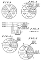
- FIG. 1 A typical prior art six sector cell site is illustrated in Fig. 1. There is a single antenna transmitting and receiving in each 60 o sector labelled sector A to sector F.
- Fig. 1 illustrates an idealized situation in which the coverage of the antennas matches the sectors exactly. In reality, the coverage of each antenna overlaps the sector boundary. This is illustrated in Fig. 2 where the shaded region 10 represents the approximate coverage of the antenna 11 of sector A.
- a commonly used diversity arrangement is that of providing two receiving antennas separated spatially by a distance of a number of wavelengths in each sector.
- the antennas may be separated horizontally or vertically.
- the arrangement provides that the two receive antennas are then combined/selected to implement diversity reception. This method requires a total of twelve receive antennas to implement a six sector site.
- TACS Total Access Communications System
- One implementation difficulty with this scheme is that the receiver must now use one main receive antenna and choose between two other antennas, making a total of three receive antennas possible for each sector. This selection may be achieved, in the TACS system, using a scan receiver as shown in Fig. 3.
- the scan receiver 12 measures the average signal level on receive antennas B and F and the antenna with the larger signal is used with the main antenna A to feed the diversity receiver 13.
- a sectorized cellular radio base station antenna comprising: a plurality of angularly separated directional transmit antennas, each transmit antenna having a central axis of transmission, for serving mobile units located in sectors centred on the axis of transmission of the transmit antennas; a plurality of angularly separated directional receive antennas, each having a central axis of reception; and diversity combining means for combining signals from adjacent receive antennas; characterized in that the central axis of the receiving antennas are at an angular offset to the central axis of the transmit antennas and, for a mobile in a given sector served by a given transmit antenna, the diversity combining means are arranged to combine the signals from the two receive antennas the axes of which lie on either side of that transmit antenna axis.
- each receive antenna has an area of reception overlapping substantially half of the area of reception of each adjacent receive antenna. In this way, a signal from any point in the cell can be received clearly at two antennas. Moreover, it is preferred that the central axis of each receive antenna approximately bisects the angle between the central axis of two adjacent transmit antennas (and the central axis of each transmit antenna approximately bisects the angle between the central axis of two adjacent receive antennas). With this combination of features, the area of overlap of two receive antennas extends across a complete sector served by the transmit antenna.
- the invention can be extended to diversity in transmission, with two adjacent transmit antennas serving a sector centred on a given receive antenna.
- Fig. 1 is a diagrammatical representation of a six sector cell.
- Fig. 2 is a diagrammatic representation of the cell of Fig. 1 and the receive area of a receive antenna in accordance with the prior art.
- Fig. 3 is a diagrammatic representation of a diversity receiver in accordance with the prior art.
- Fig. 4 is a diagrammatic representation of a cell and the transmission area of a transmit antenna according to a preferred embodiment of the invention.
- Fig. 5 is a diagrammatic representation of the cell of Figure 4 and the area of coverage of a receive antenna according to the preferred embodiment of the invention.
- Fig. 6 is a block diagram representing the receive circuitry of a GSM base station according to a first embodiment of the invention.
- Fig. 7 is a block diagram of the receive circuitry of a GSM base station according to a second embodiment of the invention.
- a six-sector cell is illustrated and the shaded area 20 represents the area of coverage of a transmit antenna designated transmit antenna A having its central axis of transmission in the centre of sector A.
- the angle of coverage of the antenna is approximately 120 o such that approximately half of sector B and half of sector F are covered by transmit antenna A.
- Each of the other six sectors B - F has a corresponding transmit antenna having a 120 o angle. Every point on the circle is covered by two transmit antennas, although this is incidental to the preferred embodiment of the present invention.
- the same cell is shown as is shown in Fig. 4 and the shaded area 21 represents the area of reception of one receive antenna 30 designated antenna A/F.
- the receive antenna has an area of coverage of approximately 120 o and its central axis of reception is directed along the nominal boundary between sector A and sector F. This boundary is described as "nominal” because it has no physical attribute.
- Another five receive antennas are provided having their central axes centred over the other five nominal boundaries between the various cells.
- the receive antennas are distributed at 60 o intervals, which intervals are off set from the corresponding central axis of the transmit antennas of Figure 4 by a constant offset of 30 o . It will be appreciated that one "sector" is now fully covered by one transmit antenna and two receive antennas. (From the print of view of transmission diversity, if implemented, one "sector" can be considered to be fully covered by two transmit antennas and one receive antenna)
- FIG. 6 the six receive antennas of Fig. 5 are shown numbered 30 - 35. Each is connected to a splitter 36 - 40, each of which splits the received signal to a different radio channel unit (RCU) 41 - 46.
- RCU radio channel unit
- Each of the RCUs 41 - 46 is an individual two-port diversity receive unit available from Motorola European Cellular Infrastructure Division, 16 Euro Way, Blagrove, Swindon, Wiltshire, SM5 8YW.
- RCUs are available from the above address in complete base station cabinets, four RCUs to a cabinet together with corresponding circuitry for four transmit antennas. The cabinets are available under model number BTS-4D. Thus, the entire circuitry of Figure 6 can be assembled from two BTS-4D cabinets with two surplus RCUs which may be used for redundancy in the event of RCU failures.
- Each RCU has two ports, shown as ports 47 and 48 in the case of RCU 41.
- each of these ports would either receive a signal from its own separate antenna (requiring twelve receive antennas in total) or from a selection matrix where the first port 47 is connected to its dedicated antenna and the second port 48 is capable of receiving its signal selectively from a splitter of one of the adjacent antennas.
- the arrangement of Fig. 6 is somewhat simplified in that the port 48 is permanently connected to the splitter of the adjacent antenna.
- Each radio channel unit 41 - 46 is also connected, to a transmit antenna 47 - 52.
- the transmit antennas 47 - 52 are all at 30 o offsets to the receive antennas 30 - 35.
- the call When a call is set up to a mobile 60 located, for example, in sector A, the call is set up through transmit antenna 47 and is simultaneously received through receive antennas 30 and 31.
- the received signal passes through splitters 36 and 37 to ports 47 and 48 of RCU 41.
- the outgoing and incoming paths of the same call pass through the same RCU and for each transmit sector there are always two receive antennas connected to the RCU for that transmit sector.
- Fig. 7 shows an arrangement which is alternative to that of Fig. 6, where the further feature of dynamic allocation of the RCUs is provided.
- switch matrices 70 and 71 on the receive and transmit sides respectively.
- the transmit matrix 70 connects the splitters 36 - 40 to the input ports of the RCUs 41 - 46.
- the switch matrix 71 connects the transmit outputs of the RCUs 41 - 46 to the transmit antennas 47 - 52.
- Switch matrices 70 and 71 simultaneously switch the receive ports and the transmit port of any RCU (for example RCU 41) to any pair of receive antennas (e.g. antennas 31 and 32 as shown) via their respective splitters and to the corresponding transmit antenna (e.g. transmit antenna 48). In this way any RCU can be dynamically allocated to any sector of the cell in a given time slot.
- the switch matrices 70 and 71 can switch on a slot-by-slot basis.
- the arrangement has various advantages over that shown in Figure 6, including that of allowing the sharing of operational RCUs in the event of failure of another RCU. It should be noted that the switching of an RCU to a particular sector is not dependent on any signal strength or diversity decision, but on other factors.
- the pair of receive antennas to which the two diversity receive ports of an RCU are connected always cover the sector of the cell corresponding to the transmit antenna to which the transmit port is connected.
- the RCUs 41 - 46 are, in the cases of the arrangements of Fig. 6 and Fig. 7, connected to a CEPT 2Mbit/s interface linking the base station to a mobile switching centre. These details are not shown in the figures but can be found in UK patent application No. 9110258.
Abstract

Description
- This invention relates to sectorized cellular radio base station antennas and in particular it concerns the radio technique known as "antenna space diversity". The invention can be utilized in many radio systems, but is particularly applicable to the digital Groupe Special Mobile (GSM) digital European cellular radio system.
- Radio links between mobile stations and base stations must tolerate multipath signals which are reflected off buildings and other objects. In general, the received signal is the vector sum of a number of delayed signals returned via a number of transmissions paths. The signal at the receive antenna shows the results of this multipath reception as constructive and destructive interference as the stations move, and the signal exhibits random deep fades causing dropouts in the received signal.
- Antenna Space Diversity is a technique used which employs two receive antennas which are separated spatially so that the fades received at the antennas are uncorrelated. The signals from these two antennas are then processed in a combining/selecting device to give improved receive performance over that achievable with one antenna. A simple example of this method is to select the signal from the receiver with the strongest received signal, although, other combining methods are possible.
- A typical prior art six sector cell site is illustrated in Fig. 1. There is a single antenna transmitting and receiving in each 60o sector labelled sector A to sector F.
- Fig. 1 illustrates an idealized situation in which the coverage of the antennas matches the sectors exactly. In reality, the coverage of each antenna overlaps the sector boundary. This is illustrated in Fig. 2 where the
shaded region 10 represents the approximate coverage of theantenna 11 of sector A. - A commonly used diversity arrangement is that of providing two receiving antennas separated spatially by a distance of a number of wavelengths in each sector. The antennas may be separated horizontally or vertically. The arrangement provides that the two receive antennas are then combined/selected to implement diversity reception. This method requires a total of twelve receive antennas to implement a six sector site.
- Another method which is implemented with the Total Access Communications System (TACS) uses the overlapping of the antennas from adjacent sectors to reduce the number of antennas required for a six sector site to a total of six. This requires the receive antennas to be spatially separated by a number of wavelengths - which is normally the case on a standard site. Whilst in sector A the receive path in sectors B and F can be monitored and if found to be better than the receive path in sector A, the appropriate antenna can be switched into the receiver in preference to the antenna for sector A. It can be seen that this scheme would enhance the performance of the radio transmission.
- One implementation difficulty with this scheme is that the receiver must now use one main receive antenna and choose between two other antennas, making a total of three receive antennas possible for each sector. This selection may be achieved, in the TACS system, using a scan receiver as shown in Fig. 3. The
scan receiver 12 measures the average signal level on receive antennas B and F and the antenna with the larger signal is used with the main antenna A to feed thediversity receiver 13. - Unfortunately, there are considerable practical difficulties inherent in the implementation of this shared diversity scheme when translated to the GSM system. In a GSM system it is inconvenient to provide a scan receiver and there is a need for alternative arrangement for selecting the correct antenna pair.
- Consider a mobile in sector A trying to establish a call to the base station in the cell. The mobile will send a channel request which will be received on the antenna in sector A. At this stage there is no mechanism for knowing whether antenna B or antenna F is the best candidate for the second antenna to be used in the diversity algorithm, so the best that can be done is to choose one at random (for example always favouring the antennas in the clockwise direction). With such a scheme there is a fair chance that no gain in performance will be achieved in the performance of the RACh (Random Access Channel) from the diversity over the no-diversity case.
- Even when a TCh (Traffic Channel) or SDCCh (Standalone Dedicated Control Channel) has been established, there are practical difficulties with the shared diversity algorithm because, whilst in sector A, both the receive paths from sectors B and F must be monitored to ensure that the best antennas for the diversity algorithm are utilized. Thus, for instance if at one time antennas A and F were being used to achieve shared diversity, then periodically antenna B would have to be monitored to establish whether it has a better receive path than antenna F. If it did then antenna B would be switched in rather than antenna F.
- This continuous switching and monitoring causes a prohibitively large overhead in complexity. Also, during the time in which the sampling of antennas is taking place the performance of the receiver is not optimised.
- According to the invention, a sectorized cellular radio base station antenna is provided comprising:
a plurality of angularly separated directional transmit antennas, each transmit antenna having a central axis of transmission, for serving mobile units located in sectors centred on the axis of transmission of the transmit antennas;
a plurality of angularly separated directional receive antennas, each having a central axis of reception; and
diversity combining means for combining signals from adjacent receive antennas;
characterized in that the central axis of the receiving antennas are at an angular offset to the central axis of the transmit antennas and, for a mobile in a given sector served by a given transmit antenna, the diversity combining means are arranged to combine the signals from the two receive antennas the axes of which lie on either side of that transmit antenna axis. - It will be understood that the expression "combined" extends to selection, equal gain combining and maximum ratio combining.
- By offsetting or rotating the receive antennas by an angle, for example 30o, to the transmit antennas, the necessity of choosing between candidates for the second antenna to be used for diversity is avoided. This provides for simplicity and efficiency.
- It is preferred that each receive antenna has an area of reception overlapping substantially half of the area of reception of each adjacent receive antenna. In this way, a signal from any point in the cell can be received clearly at two antennas. Moreover, it is preferred that the central axis of each receive antenna approximately bisects the angle between the central axis of two adjacent transmit antennas (and the central axis of each transmit antenna approximately bisects the angle between the central axis of two adjacent receive antennas). With this combination of features, the area of overlap of two receive antennas extends across a complete sector served by the transmit antenna.
- The invention can be extended to diversity in transmission, with two adjacent transmit antennas serving a sector centred on a given receive antenna.
- Preferred embodiments of the invention will now be described, by way of example only, with reference to the accompanying drawings.
- Fig. 1 is a diagrammatical representation of a six sector cell.
- Fig. 2 is a diagrammatic representation of the cell of Fig. 1 and the receive area of a receive antenna in accordance with the prior art.
- Fig. 3 is a diagrammatic representation of a diversity receiver in accordance with the prior art.
- Fig. 4 is a diagrammatic representation of a cell and the transmission area of a transmit antenna according to a preferred embodiment of the invention.
- Fig. 5 is a diagrammatic representation of the cell of Figure 4 and the area of coverage of a receive antenna according to the preferred embodiment of the invention.
- Fig. 6 is a block diagram representing the receive circuitry of a GSM base station according to a first embodiment of the invention.
- Fig. 7 is a block diagram of the receive circuitry of a GSM base station according to a second embodiment of the invention.
- Referring to Fig. 4, a six-sector cell is illustrated and the shaded area 20 represents the area of coverage of a transmit antenna designated transmit antenna A having its central axis of transmission in the centre of sector A. The angle of coverage of the antenna is approximately 120o such that approximately half of sector B and half of sector F are covered by transmit antenna A. Each of the other six sectors B - F has a corresponding transmit antenna having a 120o angle. Every point on the circle is covered by two transmit antennas, although this is incidental to the preferred embodiment of the present invention.
- Referring to Fig. 5, the same cell is shown as is shown in Fig. 4 and the
shaded area 21 represents the area of reception of one receiveantenna 30 designated antenna A/F. The receive antenna has an area of coverage of approximately 120o and its central axis of reception is directed along the nominal boundary between sector A and sector F. This boundary is described as "nominal" because it has no physical attribute. Another five receive antennas are provided having their central axes centred over the other five nominal boundaries between the various cells. Thus, the receive antennas are distributed at 60o intervals, which intervals are off set from the corresponding central axis of the transmit antennas of Figure 4 by a constant offset of 30o. It will be appreciated that one "sector" is now fully covered by one transmit antenna and two receive antennas. (From the print of view of transmission diversity, if implemented, one "sector" can be considered to be fully covered by two transmit antennas and one receive antenna) - Referring now to Fig. 6, the six receive antennas of Fig. 5 are shown numbered 30 - 35. Each is connected to a splitter 36 - 40, each of which splits the received signal to a different radio channel unit (RCU) 41 - 46. Each of the RCUs 41 - 46 is an individual two-port diversity receive unit available from Motorola European Cellular Infrastructure Division, 16 Euro Way, Blagrove, Swindon, Wiltshire, SM5 8YW. RCUs are available from the above address in complete base station cabinets, four RCUs to a cabinet together with corresponding circuitry for four transmit antennas. The cabinets are available under model number BTS-4D. Thus, the entire circuitry of Figure 6 can be assembled from two BTS-4D cabinets with two surplus RCUs which may be used for redundancy in the event of RCU failures.
- Each RCU has two ports, shown as
ports RCU 41. In a prior art arrangement, each of these ports would either receive a signal from its own separate antenna (requiring twelve receive antennas in total) or from a selection matrix where thefirst port 47 is connected to its dedicated antenna and thesecond port 48 is capable of receiving its signal selectively from a splitter of one of the adjacent antennas. By contrast, the arrangement of Fig. 6 is somewhat simplified in that theport 48 is permanently connected to the splitter of the adjacent antenna. - Each radio channel unit 41 - 46 is also connected, to a transmit antenna 47 - 52. The transmit antennas 47 - 52 are all at 30o offsets to the receive antennas 30 - 35.
- When a call is set up to a mobile 60 located, for example, in sector A, the call is set up through transmit
antenna 47 and is simultaneously received through receiveantennas splitters 36 and 37 toports RCU 41. Thus, the outgoing and incoming paths of the same call pass through the same RCU and for each transmit sector there are always two receive antennas connected to the RCU for that transmit sector. - Fig. 7 shows an arrangement which is alternative to that of Fig. 6, where the further feature of dynamic allocation of the RCUs is provided. In Fig. 7, in addition to the elements shown in Fig. 6, there are
switch matrices matrix 70 connects the splitters 36 - 40 to the input ports of the RCUs 41 - 46. Theswitch matrix 71 connects the transmit outputs of the RCUs 41 - 46 to the transmit antennas 47 - 52. -
Switch matrices e.g. antennas switch matrices - The RCUs 41 - 46 are, in the cases of the arrangements of Fig. 6 and Fig. 7, connected to a CEPT 2Mbit/s interface linking the base station to a mobile switching centre. These details are not shown in the figures but can be found in UK patent application No. 9110258.
Claims (10)
- A sectorized cellular radio base station antenna comprising:
a plurality of angularly separated directional tranmit antennas (47-52), each transmit antenna having a central axis of transmission, for serving mobile units (60) located in sectors centred on the axes of transmission of the transmit antennas;
a plurality of angularly separated directional receive antennas (30-35), each having a central axis of reception; and
diversity combining means (41) for combining signals from adjacent receive antennas; characterized in that
the central axes of the receive antennas are at an angular offset to the central axes of the transmit antennas and, for a mobile in a given sector served by a given transmit antenna, the diversity combining means are arranged to diversity combine the signals from the two receive antennas the axes of which lie on either side of that transmit antenna axis. - An antenna according to claim 1, wherein each transmit antenna has an area of transmission overlapping substantially half of the area of transmission of each adjacent transmit antenna.
- An antenna according to claim 1 or 2, wherein each receive antenna has an area of reception overlapping substantially half of the area of reception of each adjacent transmit antenna.
- An antenna according to any one of claims 1 to 3, wherein the central axis of each receive antenna approximately bisects the angle between the central axes of two adjacent transmit antennas.
- An antenna according to any one of claims 1 to 4, wherein the diversity combining means comprise selection means for selecting the signal of greater strength from the signals from the two receive antennas.
- An antenna according to any one of claims 1 to 4, further comprising maximum ratio diversity combining means for combining the signals from the two antennas in weighted proportions.
- An antenna according to any one of the preceding claims comprising six transmit antennas at evenly distributed angles around the base station and six receive antennas at evenly distributed angles around the base station.
- A base station comprising an antenna according to any one of the preceding claims in combination with a plurality of radio transceivers (41-46), each having first and second diversity receive ports and a plurality of splitter means (36-40), each splitter means connecting one receive antenna to diversity receive ports of two transceivers.
- A base station according to claim 8, further comprising switching means connecting the splitters to the transceivers and connecting the transceivers to the transmit antennas, and control means (72) for selectively connecting a transceiver simultaneously to:(a) a transmit antenna and(b) a splitter connected to the two receive antennas the axes of which lie on either side of the axis of that transmit antenna.
- A sectorized cellular radio base station antenna comprising:
a plurality of angularly separated directional receive antennas (30-35), each receive antenna having a central axis of reception, for serving mobile units located in sectors centred on the axes of reception of the receive antennas;
a plurality of angularly separated directional transmit antennas (47-48), each having a central axis of transmission; and
splitter means (36-40) for splitting transmit signals to adjacent transmit antennas; characterized in that
the central axes of the transmit antennas are at an angular offset to the central axes of the receive antennas and, for a mobile in a given sector served by a given receive antenna, the splitter means are arranged to pass a transmit signal to two transmit antennas, the axes of which lie on either side of that receive antenna axis.
Applications Claiming Priority (2)
| Application Number | Priority Date | Filing Date | Title |
|---|---|---|---|
| GB9220823A GB2271246B (en) | 1992-10-03 | 1992-10-03 | Sectorized cellular radio base station antenna |
| GB9220823 | 1992-10-03 |
Publications (3)
| Publication Number | Publication Date |
|---|---|
| EP0591770A2 true EP0591770A2 (en) | 1994-04-13 |
| EP0591770A3 EP0591770A3 (en) | 1995-03-08 |
| EP0591770B1 EP0591770B1 (en) | 2000-03-01 |
Family
ID=10722907
Family Applications (1)
| Application Number | Title | Priority Date | Filing Date |
|---|---|---|---|
| EP93115316A Expired - Lifetime EP0591770B1 (en) | 1992-10-03 | 1993-09-23 | Sectorized cellular radio base station antenna |
Country Status (9)
| Country | Link |
|---|---|
| US (1) | US5742911A (en) |
| EP (1) | EP0591770B1 (en) |
| CN (1) | CN1047045C (en) |
| AT (1) | ATE190174T1 (en) |
| AU (1) | AU665670B2 (en) |
| DE (1) | DE69327930T2 (en) |
| ES (1) | ES2142843T3 (en) |
| FI (1) | FI934337A (en) |
| GB (1) | GB2271246B (en) |
Cited By (10)
| Publication number | Priority date | Publication date | Assignee | Title |
|---|---|---|---|---|
| WO1995022210A2 (en) * | 1994-02-14 | 1995-08-17 | Qualcomm Incorporated | Dynamic sectorization in a spread spectrum communication system |
| WO1996000466A1 (en) * | 1994-06-23 | 1996-01-04 | Qualcomm Incorporated | Adaptive sectorization in a spread spectrum communication system |
| WO1996015642A1 (en) * | 1994-11-15 | 1996-05-23 | Telefonaktiebolaget Lm Ericsson | Dynamic channel allocation for sectorized radio access units of a mobile communication system |
| EP0734194A1 (en) * | 1995-03-22 | 1996-09-25 | Siemens Aktiengesellschaft | Radio communications system with central illumination by sector antennae |
| WO1997037441A1 (en) * | 1996-04-03 | 1997-10-09 | Ericsson Inc. | Method and apparatus for polarization diversity in a base station using a plurality of reception antennas |
| WO1998054786A1 (en) * | 1997-05-28 | 1998-12-03 | France Telecom | Communication method between a base station with n antennae and a mobile phone and base station for implementing same |
| EP1014740A1 (en) * | 1998-12-22 | 2000-06-28 | Motorola, Inc. | Reduction of co-channel interference in cellular communications systems |
| US6091788A (en) * | 1995-05-24 | 2000-07-18 | Nokia Telecommunications Oy | Base station equipment and a method for steering an antenna beam |
| EP1199816A1 (en) * | 1999-07-05 | 2002-04-24 | NEC Corporation | Radio base station and method of preventing failure of radio function |
| EP1211908A2 (en) * | 1996-10-11 | 2002-06-05 | Ericsson Inc. | Interstitial sector system |
Families Citing this family (53)
| Publication number | Priority date | Publication date | Assignee | Title |
|---|---|---|---|---|
| GB9402942D0 (en) * | 1994-02-16 | 1994-04-06 | Northern Telecom Ltd | Base station antenna arrangement |
| FI944346A (en) * | 1994-09-19 | 1996-03-20 | Nokia Telecommunications Oy | Base station |
| DE19510534B4 (en) * | 1995-03-23 | 2004-01-29 | Siemens Ag | Reception and transmission methods for a system for non-wired duplex transmission |
| GB9508639D0 (en) * | 1995-04-28 | 1995-06-14 | Ionica Int Ltd | Frequency assignment in a cellular radio telecommunications network |
| DE19535441A1 (en) * | 1995-09-23 | 1997-03-27 | Bosch Gmbh Robert | Antenna of a central station of a point-to-multipoint radio relay system |
| GB9525942D0 (en) * | 1995-12-19 | 1996-02-21 | Nokia Telecommunications Oy | Channel allocation in a radio telephone system |
| JPH1023520A (en) * | 1996-07-02 | 1998-01-23 | Matsushita Electric Ind Co Ltd | Zone constituting method and transmission device utilizing the method |
| KR19980064467A (en) * | 1996-12-23 | 1998-10-07 | 윌리엄비.켐플러 | Point-to-Multipoint Communication System with Subsector Upstream Antenna |
| US5913177A (en) * | 1997-03-31 | 1999-06-15 | Radio Frequency Systems, Inc. | Traffic distribution analysis in a land mobile radio system |
| US5960349A (en) * | 1997-05-20 | 1999-09-28 | Northern Telecom | Enhanced cellular layout for CDMA networks having six-sectored cells |
| US6151512A (en) * | 1997-05-28 | 2000-11-21 | Nortel Networks Corporation | Communication system having optimum resource arrangements in a multi-sectored environment and method therefor |
| US6195556B1 (en) * | 1997-07-15 | 2001-02-27 | Metawave Communications Corporation | System and method of determining a mobile station's position using directable beams |
| US6097931A (en) * | 1997-08-20 | 2000-08-01 | Wireless Online, Inc. | Two-way paging uplink infrastructure |
| FI104300B1 (en) * | 1997-08-22 | 1999-12-15 | Nokia Telecommunications Oy | Adaptive radio system |
| US6188914B1 (en) * | 1997-10-22 | 2001-02-13 | Nortel Networks Limited | Method and apparatus for improving link performance and capacity of a sectorized CDMA cellular communication network |
| US6351654B1 (en) * | 1997-10-23 | 2002-02-26 | Lucent Technologies Inc. | Antenna configuration for a hybrid inner/outer sectored cell |
| US6041232A (en) * | 1997-12-23 | 2000-03-21 | Sc-Wireless Inc. | Aggregation of shaped directional receiving antenna array for improved location information |
| US6148218A (en) * | 1998-02-13 | 2000-11-14 | Lucent Technologies, Inc. | Architecture for multi-sector base stations |
| US6539239B1 (en) * | 1998-02-13 | 2003-03-25 | Lucent Technologies, Inc. | Wireless telecommunications system architecture supporting receive diversity |
| JP3464606B2 (en) * | 1998-03-31 | 2003-11-10 | 松下電器産業株式会社 | Wireless communication device and wireless communication method |
| US6141543A (en) * | 1998-04-13 | 2000-10-31 | Motorola, Inc. | Method and apparatus for simulcast space diversity transmission of a message in a radio messaging system |
| KR100262523B1 (en) | 1998-06-03 | 2000-08-01 | 윤종용 | Improvement method of call setup through indirect access in a base station of mobile telecommunication system |
| KR100285734B1 (en) * | 1998-06-23 | 2001-04-02 | 윤종용 | Multiple Sectorizer of Base Station System |
| US6714528B1 (en) * | 1998-08-05 | 2004-03-30 | Samsung Electronics Co., Ltd. | Device and method for diversity combining signals on common channel in CDMA communication system |
| US6161024A (en) * | 1998-10-15 | 2000-12-12 | Airnet Communications Corporations | Redundant broadband multi-carrier base station for wireless communications using omni-directional overlay on a tri-sectored wireless system |
| FR2805119B1 (en) * | 2000-02-16 | 2003-02-07 | Mitsubishi Electric Inf Tech | METHOD FOR DISTRIBUTING COMMUNICATIONS WITHIN A CELL OF A RADIO COMMUNICATION NETWORK, CORRESPONDING DEVICE AND BASE STATION |
| US8363744B2 (en) | 2001-06-10 | 2013-01-29 | Aloft Media, Llc | Method and system for robust, secure, and high-efficiency voice and packet transmission over ad-hoc, mesh, and MIMO communication networks |
| JP3498704B2 (en) * | 2000-12-12 | 2004-02-16 | 日本電気株式会社 | Radio channel control device, method of improving reception characteristics thereof, and recording medium recording reception characteristics improvement program |
| GB2372173B (en) * | 2001-02-08 | 2003-05-14 | Adaptive Broadband Ltd | Increasing capacity and improving coverage of a cellular radio network |
| US6665897B2 (en) * | 2001-06-06 | 2003-12-23 | Lionel A. Walpin | Crown bed |
| US7065383B1 (en) | 2002-04-16 | 2006-06-20 | Omri Hovers | Method and apparatus for synchronizing a smart antenna apparatus with a base station transceiver |
| US7289826B1 (en) | 2002-04-16 | 2007-10-30 | Faulkner Interstices, Llc | Method and apparatus for beam selection in a smart antenna system |
| US7529525B1 (en) | 2002-04-16 | 2009-05-05 | Faulkner Interstices Llc | Method and apparatus for collecting information for use in a smart antenna system |
| US7346365B1 (en) * | 2002-04-16 | 2008-03-18 | Faulkner Interstices Llc | Smart antenna system and method |
| EP1756969B1 (en) * | 2004-06-15 | 2008-03-05 | TELEFONAKTIEBOLAGET LM ERICSSON (publ) | Antenna diversity arrangement and method |
| DE102004049895A1 (en) * | 2004-10-13 | 2006-04-20 | Airbus Deutschland Gmbh | Interface device for a communications network for multiple electronic units in an aircraft has a switching unit and send and receive antennae for unique connection of any of a 1st node group to any of a wireless 2nd node group |
| US9179336B2 (en) | 2013-02-19 | 2015-11-03 | Mimosa Networks, Inc. | WiFi management interface for microwave radio and reset to factory defaults |
| US9930592B2 (en) | 2013-02-19 | 2018-03-27 | Mimosa Networks, Inc. | Systems and methods for directing mobile device connectivity |
| WO2014138292A1 (en) | 2013-03-06 | 2014-09-12 | Mimosa Networks, Inc. | Enclosure for radio, parabolic dish antenna, and side lobe shields |
| WO2014137370A1 (en) | 2013-03-06 | 2014-09-12 | Mimosa Networks, Inc. | Waterproof apparatus for cables and cable interfaces |
| US10742275B2 (en) * | 2013-03-07 | 2020-08-11 | Mimosa Networks, Inc. | Quad-sector antenna using circular polarization |
| US9191081B2 (en) | 2013-03-08 | 2015-11-17 | Mimosa Networks, Inc. | System and method for dual-band backhaul radio |
| US9295103B2 (en) | 2013-05-30 | 2016-03-22 | Mimosa Networks, Inc. | Wireless access points providing hybrid 802.11 and scheduled priority access communications |
| US10938110B2 (en) | 2013-06-28 | 2021-03-02 | Mimosa Networks, Inc. | Ellipticity reduction in circularly polarized array antennas |
| US9001689B1 (en) | 2014-01-24 | 2015-04-07 | Mimosa Networks, Inc. | Channel optimization in half duplex communications systems |
| US9780892B2 (en) | 2014-03-05 | 2017-10-03 | Mimosa Networks, Inc. | System and method for aligning a radio using an automated audio guide |
| US9998246B2 (en) | 2014-03-13 | 2018-06-12 | Mimosa Networks, Inc. | Simultaneous transmission on shared channel |
| US10958332B2 (en) | 2014-09-08 | 2021-03-23 | Mimosa Networks, Inc. | Wi-Fi hotspot repeater |
| WO2017123558A1 (en) | 2016-01-11 | 2017-07-20 | Mimosa Networks, Inc. | Printed circuit board mounted antenna and waveguide interface |
| US11251539B2 (en) | 2016-07-29 | 2022-02-15 | Airspan Ip Holdco Llc | Multi-band access point antenna array |
| US10511074B2 (en) | 2018-01-05 | 2019-12-17 | Mimosa Networks, Inc. | Higher signal isolation solutions for printed circuit board mounted antenna and waveguide interface |
| WO2019168800A1 (en) | 2018-03-02 | 2019-09-06 | Mimosa Networks, Inc. | Omni-directional orthogonally-polarized antenna system for mimo applications |
| US11289821B2 (en) | 2018-09-11 | 2022-03-29 | Air Span Ip Holdco Llc | Sector antenna systems and methods for providing high gain and high side-lobe rejection |
Citations (5)
| Publication number | Priority date | Publication date | Assignee | Title |
|---|---|---|---|---|
| US4369520A (en) * | 1979-03-22 | 1983-01-18 | Motorola, Inc. | Instantaneously acquiring sector antenna combining system |
| US4727590A (en) * | 1986-09-05 | 1988-02-23 | Mitsubishi Denki Kabushiki Kaisha | Mobile radio communication system with repeater station grid |
| WO1988008140A1 (en) * | 1987-04-08 | 1988-10-20 | M/A-Com, Inc. | Mobile radio network for nationwide communications |
| EP0429200A2 (en) * | 1989-11-16 | 1991-05-29 | Gec-Marconi Limited | Broadcast networks |
| WO1993012586A1 (en) * | 1991-12-16 | 1993-06-24 | Detecon Deutsche Telepost Consulting Gmbh | Process for improving the coverage of radio cells in a cellular mobile radio system and device for implementing it |
Family Cites Families (6)
| Publication number | Priority date | Publication date | Assignee | Title |
|---|---|---|---|---|
| US4597105A (en) * | 1982-11-12 | 1986-06-24 | Motorola Inc. | Data communications system having overlapping receiver coverage zones |
| US4639914A (en) * | 1984-12-06 | 1987-01-27 | At&T Bell Laboratories | Wireless PBX/LAN system with optimum combining |
| DE69024339T2 (en) * | 1989-12-28 | 1996-08-14 | Nec Corp | Antenna system to reduce mutual interference when using the same channels |
| US5119501A (en) * | 1990-04-19 | 1992-06-02 | Ericsson Ge Mobile Communications, Inc. | Adaptive diversity equipment arrangement for cellular mobile telephone systems |
| US5276907A (en) * | 1991-01-07 | 1994-01-04 | Motorola Inc. | Method and apparatus for dynamic distribution of a communication channel load in a cellular radio communication system |
| DE4290393C2 (en) * | 1991-02-22 | 1998-05-20 | Motorola Inc | Method and device for improving the signal quality of a signal transmitted in a transmission channel of a cellular communication system |
-
1992
- 1992-10-03 GB GB9220823A patent/GB2271246B/en not_active Expired - Fee Related
-
1993
- 1993-09-23 AT AT93115316T patent/ATE190174T1/en active
- 1993-09-23 ES ES93115316T patent/ES2142843T3/en not_active Expired - Lifetime
- 1993-09-23 EP EP93115316A patent/EP0591770B1/en not_active Expired - Lifetime
- 1993-09-23 DE DE69327930T patent/DE69327930T2/en not_active Expired - Fee Related
- 1993-09-24 AU AU47558/93A patent/AU665670B2/en not_active Ceased
- 1993-09-29 CN CN93118178A patent/CN1047045C/en not_active Expired - Fee Related
- 1993-10-01 FI FI934337A patent/FI934337A/en unknown
-
1996
- 1996-06-04 US US08/658,985 patent/US5742911A/en not_active Expired - Fee Related
Patent Citations (5)
| Publication number | Priority date | Publication date | Assignee | Title |
|---|---|---|---|---|
| US4369520A (en) * | 1979-03-22 | 1983-01-18 | Motorola, Inc. | Instantaneously acquiring sector antenna combining system |
| US4727590A (en) * | 1986-09-05 | 1988-02-23 | Mitsubishi Denki Kabushiki Kaisha | Mobile radio communication system with repeater station grid |
| WO1988008140A1 (en) * | 1987-04-08 | 1988-10-20 | M/A-Com, Inc. | Mobile radio network for nationwide communications |
| EP0429200A2 (en) * | 1989-11-16 | 1991-05-29 | Gec-Marconi Limited | Broadcast networks |
| WO1993012586A1 (en) * | 1991-12-16 | 1993-06-24 | Detecon Deutsche Telepost Consulting Gmbh | Process for improving the coverage of radio cells in a cellular mobile radio system and device for implementing it |
Cited By (22)
| Publication number | Priority date | Publication date | Assignee | Title |
|---|---|---|---|---|
| WO1995022210A2 (en) * | 1994-02-14 | 1995-08-17 | Qualcomm Incorporated | Dynamic sectorization in a spread spectrum communication system |
| WO1995022210A3 (en) * | 1994-02-14 | 1995-11-02 | Qualcomm Inc | Dynamic sectorization in a spread spectrum communication system |
| US6473447B1 (en) | 1994-02-14 | 2002-10-29 | Qualcomm Incorporated | Dynamic sectorization in a spread spectrum communication system |
| US7653149B2 (en) | 1994-02-14 | 2010-01-26 | Qualcomm Incorporated | Dynamic sectorization in a spread spectrum communication system |
| US5832389A (en) * | 1994-03-24 | 1998-11-03 | Ericsson Inc. | Wideband digitization systems and methods for cellular radiotelephones |
| WO1996000466A1 (en) * | 1994-06-23 | 1996-01-04 | Qualcomm Incorporated | Adaptive sectorization in a spread spectrum communication system |
| US5621752A (en) * | 1994-06-23 | 1997-04-15 | Qualcomm Incorporated | Adaptive sectorization in a spread spectrum communication system |
| CN1082286C (en) * | 1994-06-23 | 2002-04-03 | 夸尔柯姆股份有限公司 | Adaptive sectorization in a spread spectrum communication system |
| AU685966B2 (en) * | 1994-06-23 | 1998-01-29 | Qualcomm Incorporated | Adaptive sectorization in a spread spectrum communication system |
| WO1996015642A1 (en) * | 1994-11-15 | 1996-05-23 | Telefonaktiebolaget Lm Ericsson | Dynamic channel allocation for sectorized radio access units of a mobile communication system |
| EP0734194A1 (en) * | 1995-03-22 | 1996-09-25 | Siemens Aktiengesellschaft | Radio communications system with central illumination by sector antennae |
| US6091788A (en) * | 1995-05-24 | 2000-07-18 | Nokia Telecommunications Oy | Base station equipment and a method for steering an antenna beam |
| AU712156B2 (en) * | 1996-04-03 | 1999-10-28 | Ericsson Inc. | Wideband digitization systems and methods for cellular radiotelephones |
| WO1997037441A1 (en) * | 1996-04-03 | 1997-10-09 | Ericsson Inc. | Method and apparatus for polarization diversity in a base station using a plurality of reception antennas |
| CN100359980C (en) * | 1996-10-11 | 2008-01-02 | 艾利森公司 | Interstitial sector system |
| EP1211908A3 (en) * | 1996-10-11 | 2002-12-11 | Ericsson Inc. | Interstitial sector system |
| EP1211908A2 (en) * | 1996-10-11 | 2002-06-05 | Ericsson Inc. | Interstitial sector system |
| FR2764140A1 (en) * | 1997-05-28 | 1998-12-04 | Armand Levy | COMMUNICATION METHOD BETWEEN AN ANTENNA BASE STATION AND A MOBILE AND BASE STATION FOR CARRYING OUT THIS METHOD |
| WO1998054786A1 (en) * | 1997-05-28 | 1998-12-03 | France Telecom | Communication method between a base station with n antennae and a mobile phone and base station for implementing same |
| EP1014740A1 (en) * | 1998-12-22 | 2000-06-28 | Motorola, Inc. | Reduction of co-channel interference in cellular communications systems |
| EP1199816A1 (en) * | 1999-07-05 | 2002-04-24 | NEC Corporation | Radio base station and method of preventing failure of radio function |
| EP1199816A4 (en) * | 1999-07-05 | 2006-07-19 | Nec Corp | Radio base station and method of preventing failure of radio function |
Also Published As
| Publication number | Publication date |
|---|---|
| EP0591770B1 (en) | 2000-03-01 |
| FI934337A (en) | 1994-04-04 |
| ATE190174T1 (en) | 2000-03-15 |
| FI934337A0 (en) | 1993-10-01 |
| GB2271246A (en) | 1994-04-06 |
| DE69327930T2 (en) | 2000-11-30 |
| ES2142843T3 (en) | 2000-05-01 |
| EP0591770A3 (en) | 1995-03-08 |
| AU4755893A (en) | 1994-04-14 |
| GB2271246B (en) | 1997-02-12 |
| CN1090691A (en) | 1994-08-10 |
| DE69327930D1 (en) | 2000-04-06 |
| AU665670B2 (en) | 1996-01-11 |
| GB9220823D0 (en) | 1992-11-18 |
| CN1047045C (en) | 1999-12-01 |
| US5742911A (en) | 1998-04-21 |
Similar Documents
| Publication | Publication Date | Title |
|---|---|---|
| EP0591770B1 (en) | Sectorized cellular radio base station antenna | |
| US5714957A (en) | Base station antenna arrangement | |
| EP0647982B1 (en) | Base station antenna arrangement | |
| US5771017A (en) | Base station antenna arrangement | |
| US5576717A (en) | Base station antenna arrangement | |
| US5602555A (en) | Base station antenna arrangement | |
| US5565873A (en) | Base station antenna arrangement | |
| US6453176B1 (en) | Antenna array system | |
| US6577879B1 (en) | System and method for simultaneous transmission of signals in multiple beams without feeder cable coherency | |
| US5448753A (en) | Wide area radio communication network system and method | |
| US5666123A (en) | Base station antenna arrangement | |
| JP4481508B2 (en) | Adaptation sector | |
| EP0432198B1 (en) | Method and system in a wide area radio communication network | |
| US6212387B1 (en) | Method and apparatus for collector arrays of directional antennas co-located with zone managers in wireless communications systems | |
| US5570098A (en) | Base station antenna arrangement | |
| US6131034A (en) | Method and apparatus for collector arrays in wireless communications systems | |
| GB2281008A (en) | Base station antenna arrangement | |
| CA2000529C (en) | Method and system in a wide area radio communication network |
Legal Events
| Date | Code | Title | Description |
|---|---|---|---|
| PUAI | Public reference made under article 153(3) epc to a published international application that has entered the european phase |
Free format text: ORIGINAL CODE: 0009012 |
|
| AK | Designated contracting states |
Kind code of ref document: A2 Designated state(s): AT DE ES FR GB NL SE |
|
| PUAL | Search report despatched |
Free format text: ORIGINAL CODE: 0009013 |
|
| AK | Designated contracting states |
Kind code of ref document: A3 Designated state(s): AT DE ES FR GB NL SE |
|
| 17P | Request for examination filed |
Effective date: 19950908 |
|
| 17Q | First examination report despatched |
Effective date: 19980615 |
|
| GRAG | Despatch of communication of intention to grant |
Free format text: ORIGINAL CODE: EPIDOS AGRA |
|
| GRAG | Despatch of communication of intention to grant |
Free format text: ORIGINAL CODE: EPIDOS AGRA |
|
| GRAH | Despatch of communication of intention to grant a patent |
Free format text: ORIGINAL CODE: EPIDOS IGRA |
|
| GRAH | Despatch of communication of intention to grant a patent |
Free format text: ORIGINAL CODE: EPIDOS IGRA |
|
| GRAA | (expected) grant |
Free format text: ORIGINAL CODE: 0009210 |
|
| AK | Designated contracting states |
Kind code of ref document: B1 Designated state(s): AT DE ES FR GB NL SE |
|
| REF | Corresponds to: |
Ref document number: 190174 Country of ref document: AT Date of ref document: 20000315 Kind code of ref document: T |
|
| ET | Fr: translation filed | ||
| REF | Corresponds to: |
Ref document number: 69327930 Country of ref document: DE Date of ref document: 20000406 |
|
| REG | Reference to a national code |
Ref country code: ES Ref legal event code: FG2A Ref document number: 2142843 Country of ref document: ES Kind code of ref document: T3 |
|
| PGFP | Annual fee paid to national office [announced via postgrant information from national office to epo] |
Ref country code: NL Payment date: 20000620 Year of fee payment: 8 |
|
| PGFP | Annual fee paid to national office [announced via postgrant information from national office to epo] |
Ref country code: AT Payment date: 20000807 Year of fee payment: 8 |
|
| PGFP | Annual fee paid to national office [announced via postgrant information from national office to epo] |
Ref country code: SE Payment date: 20000901 Year of fee payment: 8 |
|
| PGFP | Annual fee paid to national office [announced via postgrant information from national office to epo] |
Ref country code: ES Payment date: 20000926 Year of fee payment: 8 |
|
| PLBE | No opposition filed within time limit |
Free format text: ORIGINAL CODE: 0009261 |
|
| STAA | Information on the status of an ep patent application or granted ep patent |
Free format text: STATUS: NO OPPOSITION FILED WITHIN TIME LIMIT |
|
| 26N | No opposition filed | ||
| PGFP | Annual fee paid to national office [announced via postgrant information from national office to epo] |
Ref country code: GB Payment date: 20010807 Year of fee payment: 9 |
|
| PGFP | Annual fee paid to national office [announced via postgrant information from national office to epo] |
Ref country code: FR Payment date: 20010831 Year of fee payment: 9 |
|
| PG25 | Lapsed in a contracting state [announced via postgrant information from national office to epo] |
Ref country code: AT Free format text: LAPSE BECAUSE OF NON-PAYMENT OF DUE FEES Effective date: 20010923 |
|
| PG25 | Lapsed in a contracting state [announced via postgrant information from national office to epo] |
Ref country code: SE Free format text: LAPSE BECAUSE OF NON-PAYMENT OF DUE FEES Effective date: 20010924 Ref country code: ES Free format text: LAPSE BECAUSE OF NON-PAYMENT OF DUE FEES Effective date: 20010924 |
|
| PGFP | Annual fee paid to national office [announced via postgrant information from national office to epo] |
Ref country code: DE Payment date: 20010927 Year of fee payment: 9 |
|
| REG | Reference to a national code |
Ref country code: GB Ref legal event code: IF02 |
|
| PG25 | Lapsed in a contracting state [announced via postgrant information from national office to epo] |
Ref country code: NL Free format text: LAPSE BECAUSE OF NON-PAYMENT OF DUE FEES Effective date: 20020401 |
|
| EUG | Se: european patent has lapsed |
Ref document number: 93115316.7 |
|
| NLV4 | Nl: lapsed or anulled due to non-payment of the annual fee |
Effective date: 20020401 |
|
| PG25 | Lapsed in a contracting state [announced via postgrant information from national office to epo] |
Ref country code: GB Free format text: LAPSE BECAUSE OF NON-PAYMENT OF DUE FEES Effective date: 20020923 |
|
| PG25 | Lapsed in a contracting state [announced via postgrant information from national office to epo] |
Ref country code: DE Free format text: LAPSE BECAUSE OF NON-PAYMENT OF DUE FEES Effective date: 20030401 |
|
| GBPC | Gb: european patent ceased through non-payment of renewal fee |
Effective date: 20020923 |
|
| NLV4 | Nl: lapsed or anulled due to non-payment of the annual fee |
Effective date: 20020401 |
|
| PG25 | Lapsed in a contracting state [announced via postgrant information from national office to epo] |
Ref country code: FR Free format text: LAPSE BECAUSE OF NON-PAYMENT OF DUE FEES Effective date: 20030603 |
|
| REG | Reference to a national code |
Ref country code: FR Ref legal event code: ST |
|
| REG | Reference to a national code |
Ref country code: ES Ref legal event code: FD2A Effective date: 20021011 |
|
| P01 | Opt-out of the competence of the unified patent court (upc) registered |
Effective date: 20230524 |