EP0590417A1 - Device for conditioning the temperature of objects - Google Patents
Device for conditioning the temperature of objects Download PDFInfo
- Publication number
- EP0590417A1 EP0590417A1 EP93114864A EP93114864A EP0590417A1 EP 0590417 A1 EP0590417 A1 EP 0590417A1 EP 93114864 A EP93114864 A EP 93114864A EP 93114864 A EP93114864 A EP 93114864A EP 0590417 A1 EP0590417 A1 EP 0590417A1
- Authority
- EP
- European Patent Office
- Prior art keywords
- trough
- medium
- designed
- objects
- transport device
- Prior art date
- Legal status (The legal status is an assumption and is not a legal conclusion. Google has not performed a legal analysis and makes no representation as to the accuracy of the status listed.)
- Granted
Links
Images

Classifications
-
- B—PERFORMING OPERATIONS; TRANSPORTING
- B65—CONVEYING; PACKING; STORING; HANDLING THIN OR FILAMENTARY MATERIAL
- B65G—TRANSPORT OR STORAGE DEVICES, e.g. CONVEYORS FOR LOADING OR TIPPING, SHOP CONVEYOR SYSTEMS OR PNEUMATIC TUBE CONVEYORS
- B65G19/00—Conveyors comprising an impeller or a series of impellers carried by an endless traction element and arranged to move articles or materials over a supporting surface or underlying material, e.g. endless scraper conveyors
- B65G19/04—Conveyors comprising an impeller or a series of impellers carried by an endless traction element and arranged to move articles or materials over a supporting surface or underlying material, e.g. endless scraper conveyors for moving bulk material in open troughs or channels
- B65G19/06—Conveyors comprising an impeller or a series of impellers carried by an endless traction element and arranged to move articles or materials over a supporting surface or underlying material, e.g. endless scraper conveyors for moving bulk material in open troughs or channels the impellers being scrapers similar in size and shape to the cross-section of the trough or channel
- B65G19/08—Conveyors comprising an impeller or a series of impellers carried by an endless traction element and arranged to move articles or materials over a supporting surface or underlying material, e.g. endless scraper conveyors for moving bulk material in open troughs or channels the impellers being scrapers similar in size and shape to the cross-section of the trough or channel and attached to a single belt, rope or chain
-
- F—MECHANICAL ENGINEERING; LIGHTING; HEATING; WEAPONS; BLASTING
- F25—REFRIGERATION OR COOLING; COMBINED HEATING AND REFRIGERATION SYSTEMS; HEAT PUMP SYSTEMS; MANUFACTURE OR STORAGE OF ICE; LIQUEFACTION SOLIDIFICATION OF GASES
- F25D—REFRIGERATORS; COLD ROOMS; ICE-BOXES; COOLING OR FREEZING APPARATUS NOT OTHERWISE PROVIDED FOR
- F25D25/00—Charging, supporting, and discharging the articles to be cooled
- F25D25/04—Charging, supporting, and discharging the articles to be cooled by conveyors
-
- F—MECHANICAL ENGINEERING; LIGHTING; HEATING; WEAPONS; BLASTING
- F25—REFRIGERATION OR COOLING; COMBINED HEATING AND REFRIGERATION SYSTEMS; HEAT PUMP SYSTEMS; MANUFACTURE OR STORAGE OF ICE; LIQUEFACTION SOLIDIFICATION OF GASES
- F25D—REFRIGERATORS; COLD ROOMS; ICE-BOXES; COOLING OR FREEZING APPARATUS NOT OTHERWISE PROVIDED FOR
- F25D3/00—Devices using other cold materials; Devices using cold-storage bodies
- F25D3/10—Devices using other cold materials; Devices using cold-storage bodies using liquefied gases, e.g. liquid air
- F25D3/11—Devices using other cold materials; Devices using cold-storage bodies using liquefied gases, e.g. liquid air with conveyors carrying articles to be cooled through the cooling space
Landscapes
- Engineering & Computer Science (AREA)
- Mechanical Engineering (AREA)
- Chemical & Material Sciences (AREA)
- Combustion & Propulsion (AREA)
- Physics & Mathematics (AREA)
- Thermal Sciences (AREA)
- General Engineering & Computer Science (AREA)
- Table Equipment (AREA)
- Freezing, Cooling And Drying Of Foods (AREA)
Abstract
Description
Die Erfindung betrifft eine Vorrichtung zum Temperieren von Gegenständen mit einem ein wärmeveränderndes Medium enthaltenden Behälter und einer Fördereinrichtung zum Fördern der Gegenstände durch das Medium.The invention relates to a device for tempering objects with a container containing a heat-changing medium and a conveyor for conveying the objects through the medium.
Üblich sind z.B. Tauchfroster zum Gefrieren von Gefriergut, die ein Bad einer kryogenen Flüssigkeit aufweisen, durch das ein Förderband läuft, das das zu gefrierende Gut aus dem Bad herausfördert. Das Gefriergut wird entweder direkt in das Bad abgeworfen oder auf ein Band aufgelegt, das das Gefriergut in das Bad befördert. Ein derartiger Tauchfroster ist beispielsweise in "Gas aktuell, Messer Griesheim GmbH, Heft 29, Ausgabe Juni 1985, Seite 10" beschrieben.Common are e.g. Immersion freezer for freezing frozen goods which have a bath of cryogenic liquid through which a conveyor belt runs which conveys the goods to be frozen out of the bath. The frozen goods are either dropped directly into the bath or placed on a belt that conveys the frozen goods into the bath. Such a freezer is described, for example, in "Gas Aktuell, Messer Griesheim GmbH, Issue 29, Edition June 1985,
Bei derartigen Tauchfrostern können Probleme auftreten, wenn die Dichte des Gefrierguts so beschaffen ist, daß das Gefriergut aufschwimmt. In diesem Fall kann das Gefriergut nicht in einer vorgegebenen Zeit durch das Bad befördert werden. Probleme treten auch bei solchen Gütern auf, die zur Materialanhäufung neigen. Beispielsweise können Fette oder Zucker miteinander oder mit dem Förderband verkleben, so daß auch in diesem Fall keine definierte Verweilzeit des Gefriergutes im Bad eingehalten werden kann, oder ein verklumptes, undefiniertes Produkt entsteht.Problems can arise with immersion freezers of this type if the density of the frozen goods is such that the frozen goods float. In this case, the frozen food cannot be transported through the bath in a predetermined time will. Problems also arise with goods that tend to accumulate material. For example, fats or sugar can stick to one another or to the conveyor belt, so that in this case too, no defined retention time of the frozen goods in the bath can be maintained, or a clumped, undefined product is formed.
Der vorliegenden Erfindung liegt die Aufgabe zugrunde, eine Vorrichtung der eingangs genannten Art zur Verfügung zu stellen, die einfach aufgebaut ist und eine definierte Verweilzeit der Gegenstände im Medium ermöglicht.The present invention has for its object to provide a device of the type mentioned, which is simple in construction and allows a defined dwell time of the objects in the medium.
Diese Aufgabe wird erfindungsgemäß dadurch gelöst, daß als Fördereinrichtung Räumelemente vorgesehen sind, die an einer außerhalb des Mediums angeordneten Transporteinrichtung befestigt sind und in das Medium hineinragen.This object is achieved in that clearing elements are provided as the conveying device, which are fastened to a transport device arranged outside the medium and protrude into the medium.
Da die Transporteinrichtung außerhalb des Mediums angeordnet ist, können keine Gegenstände an der Transporteinrichtung festkleben oder sich in der Transporteinrichtung verhaken. Die in das Medium hineinragenden Räumelemente sorgen für eine Zwangsförderung der Gegenstände, so daß keine Probleme mit Aufschwimmen oder Materialanhäufung der Gegenstände mehr auftreten. Die Gegenstände können unter Einhaltung einer definierten Verweilzeit durch das Medium befördert werden.Since the transport device is arranged outside the medium, no objects can stick to the transport device or get caught in the transport device. The clearing elements protruding into the medium force the objects so that problems with floating or material accumulation of the objects no longer occur. The objects can be transported through the medium with a defined dwell time.
Vorzugsweise füllen die Räumelemente den gesamten Querschnitt des Behälters aus, so daß auch bei z.B. kleinkörnigem Gut eine optimale Zwangsförderung gewährleistet ist.Preferably, the clearing elements fill the entire cross section of the container, so that even with e.g. small-grain goods an optimal forced promotion is guaranteed.
Die Transporteinrichtung ist zweckmäßigerweise als umlaufendes Band ausgebildet, das durch zwei außerhalb des Mediums angeordnete Umlenkrollen geführt ist. Die Räumelemente sind an der Außenfläche des umlaufenden Bandes befestigt. Auf diese Weise wird eine einfach zu fertigende Anordnung geschaffen, bei der die eigentliche Transporteinrichtung außerhalb des Mediums angeordnet ist, so daß ein Verhaken oder Festkleben von Gegenständen an der Transporteinrichtung zuverlässig verhindert wird. Es ragen lediglich die Räumelemente in das Medium, die die Zwangsförderung der Gegenstände durch das Medium bewirken. Zur Realisierung dieser Anordnung sind also im wesentlichen lediglich ein mit einem wärmeverändernden Medium gefüllter Behälter, zwei außerhalb des Mediums angeordnete Umlenkrollen sowie ein umlaufendes Band mit an dessen Außenfläche angebrachten Räumelementen erforderlich. Die Anordnung weist somit wenig bewegliche Teile auf, ist einfach zu fertigen und platzsparend. Die Räumelemente sind zweckmäßigerweise als einfache Platten ausgebildet und derart am Band befestigt, daß sie quer zur Umlaufrichtung von der Außenfläche des umlaufenden Bandes abstehen.The transport device is expediently designed as a circulating belt which is guided through two deflecting rollers arranged outside the medium. The clearing elements are attached to the outer surface of the circulating belt. To this In this way, an arrangement that is easy to manufacture is created, in which the actual transport device is arranged outside the medium, so that objects cannot get caught or stick to the transport device. Only the clearing elements protrude into the medium, which cause the objects to be positively conveyed through the medium. To implement this arrangement, essentially only a container filled with a heat-changing medium, two deflection rollers arranged outside of the medium and a circulating belt with clearing elements attached to its outer surface are required. The arrangement thus has few moving parts, is easy to manufacture and saves space. The clearing elements are expediently designed as simple plates and fastened to the belt in such a way that they protrude transversely to the circumferential direction from the outer surface of the rotating belt.
Gemäß einer anderen vorteilhaften Ausführungsform der Erfindung ist die Transporteinrichtung als mindestens eine Kette ausgebildet, die durch zwei außerhalb des Mediums angeordnete Umlenkräder geführt ist. Die zweckmäßigerweise als Platten ausgebildeten Räumelemente sind derart an der Kette befestigt, daß sie quer zur Umlaufrichtung von der Außenseite der umlaufenden Kette abstehen. Vorzugsweise werden zwei Ketten parallel zueinander durch Umlenkrollen geführt und die Räumelemente zwischen den Ketten aufgehängt.According to another advantageous embodiment of the invention, the transport device is designed as at least one chain, which is guided by two deflection wheels arranged outside the medium. The clearing elements, which are expediently designed as plates, are fastened to the chain in such a way that they protrude transversely to the direction of rotation from the outside of the rotating chain. Two chains are preferably guided parallel to one another by deflection rollers and the clearing elements are suspended between the chains.
Anstelle einer Kette kann auch ein umlaufender Keilriemen eingesetzt werden, der durch Umlenkräder geführt ist.Instead of a chain, a circumferential V-belt can be used, which is guided by idler wheels.
Die Räumelemente können gemäß einer Weiterbildung des Erfindungsgedankens auch becherförmig oder als Rechen ausgebildet sein. In Anpassung an die jeweils eingesetzten, zu temperierenden Gegenstände können die Räumelemente auch als perforierte Platten oder Gitter ausgebildet sein. Je nach Bedarf können die Räumelemente so ausgebildet sein, daß ein Teil des Mediums mitgeführt wird oder ausschließlich die Gegenstände durch das Medium gefördert werden.According to a development of the inventive concept, the clearing elements can also be cup-shaped or designed as a rake. In adaptation to the objects to be tempered in each case, the clearing elements can also be used as perforated plates or grids are formed. Depending on requirements, the clearing elements can be designed so that part of the medium is carried along or only the objects are conveyed through the medium.
Der Behälter ist vorzugsweise als langgestreckter Trog ausgebildet, wobei die Transporteinrichtung parallel zur Längsrichtung des Troges oberhalb des im Trog befindlichen Mediums angeordnet ist. Bei Verwendung eines Bandes oder einer Kette als Transporteinrichtung verläuft das Band oder die Kette parallel zur Längsrichtung des Troges. In diesem Fall sind die Umlenkrollen oder Umlenkräder an den längsseitigen Enden des Troges außerhalb des Mediums angeordnet.The container is preferably designed as an elongated trough, the transport device being arranged parallel to the longitudinal direction of the trough above the medium located in the trough. When using a belt or chain as a transport device, the belt or chain runs parallel to the longitudinal direction of the trough. In this case, the deflection rollers or deflection wheels are arranged on the longitudinal ends of the trough outside of the medium.
Der Trog weist zweckmäßigerweise einen nach oben offenen V-förmigen Querschnitt auf. Ein derartiger Trog ist sehr leicht z.B. durch Umbiegen eines Bleches zu fertigen. Falls die Transporteinrichtung als umlaufendes Band oder mindestens eine umlaufende Kette ausgebildet ist, so sind die Umlenkrollen oder Umlenkräder vorzugsweise am oberen Ende eines Schenkels des V-förmigen Querschnitts des Troges derart angeordnet, daß die Drehachsen der Umlenkrollen oder Umlenkräder senkrecht zu diesem Schenkel stehen. Bei plattenförmiger Ausbildung der Räumelemente sind die Kanten der Platten vorteilhafterweise parallel zu den Wänden des Troges angeordnet.The trough expediently has an upwardly open V-shaped cross section. Such a trough is very light e.g. to be made by bending a sheet. If the transport device is designed as a revolving belt or at least one revolving chain, the deflecting rollers or deflecting wheels are preferably arranged at the upper end of one leg of the V-shaped cross section of the trough in such a way that the axes of rotation of the deflecting rollers or deflecting wheels are perpendicular to this leg. When the broaching elements are in the form of a plate, the edges of the plates are advantageously arranged parallel to the walls of the trough.
Es sind aber auch andere Trog-/Räumelementvarianten möglich. Zum Beispiel kann der Trog auch U-förmig oder halbkreisförmig ausgebildet sein mit entsprechend angepaßter Formung der Räumelemente.However, other trough / clearing element variants are also possible. For example, the trough can also be U-shaped or semicircular with a correspondingly adapted shaping of the clearing elements.
In einer besonders bevorzugten Ausführungsform der Erfindung ist der Trog in Längsrichtung schräg nach unten geneigt. Er weist am unteren Ende eine Aufnahmeeinrichtung und am oberen Ende eine Abgabeeinrichtung für die Gegenstände auf. Die am unteren Ende des Troges aufgegebenen Gegenstände werden also vom unteren Ende des Troges durch das Medium hindurch zum oberen Ende des Troges transportiert und dort z.B. über einen nach unten offenen Schacht abgeworfen.In a particularly preferred embodiment of the invention, the trough is inclined downwards in the longitudinal direction. It has a receiving device at the lower end and a delivery device for the objects at the upper end. The objects placed at the lower end of the trough are thus transported from the lower end of the trough through the medium to the upper end of the trough and there e.g. thrown over a shaft open at the bottom.
Mit der Erfindung wird eine Vorrichtung zum Temperieren von Gegenständen geschaffen, die ein definiertes Verweilzeitspektrum der Gegenstände auch bei aufschwimmendem oder zur Materialanhäufung neigendem Gut gewährleistet. Die Vorrichtung ist sehr einfach im Aufbau und ihre Einzelteile sind leicht zu fertigen. Außerdem weist sie wenig bewegliche Teile auf, wodurch eine hohe Zuverlässigkeit erreicht wird. Darüberhinaus ist die Vorrichtung platzsparend und kann überall Verwendung finden, wo Güter temperiert werden sollen. Dabei ist die Vorrichtung nicht nur auf das klassische Einsatzgebiet von Tauchfrostern, nämlich das Gefrieren von Lebensmitteln, beschränkt, sondern kann auch z.B. zum Gefrieren von pharmazeutischen oder medizinischen Lösungen, von Gewebe- oder Bakterienkulturen und sonstigen Suspensionen eingesetzt werden.With the invention, a device for tempering objects is created, which ensures a defined dwell time spectrum of the objects even when the material is floating or tends to accumulate material. The device is very simple in construction and its individual parts are easy to manufacture. In addition, it has few moving parts, which ensures high reliability. In addition, the device is space-saving and can be used wherever goods are to be tempered. The device is not only limited to the classic field of application of immersion freezers, namely the freezing of food, but can also e.g. for freezing pharmaceutical or medical solutions, tissue or bacterial cultures and other suspensions.
Darüber hinaus eignet sich die erfindungsgemäße Vorrichtung zur Erreichung einer Reaktionsverlangsamung oder eines Reaktionsstops bei chemischen Prozessen (z.B. bei Schmelzklebern oder Reaktionsharzen). Die Vorrichtung kann auch dazu verwendet werden, ein bestimmtes Gefüge oder Kristallgitter von Metallen zu erzielen. Außer zum Abkühlen oder Gefrieren von Gegenständen kann die Vorrichtung aber auch zum Erwärmen oder Erhitzen von Gegenständen, z.B. zum Frittieren von Lebensmitteln, eigesetzt werden.In addition, the device according to the invention is suitable for achieving a reaction slowdown or a reaction stop in chemical processes (for example in the case of hot-melt adhesives or reactive resins). The device can also be used to achieve a certain structure or crystal lattice of metals. In addition to cooling or freezing objects, the device can also be used for heating or heating objects, for example for deep-frying food.
Aufgrund der erfindungsgemäß vorgesehenen Zwangsförderung der Gegenstände treten keine Probleme bei Materialien auf, die auf dem Medium aufschwimmen oder wie z.B. Fette oder Zucker zusammenkleben können.Due to the forced conveyance of the objects provided according to the invention, there are no problems with materials that float on the medium or such as e.g. Can stick fats or sugar together.
Als wärmeveränderndes Medium sind vor allem kryogene Flüssigkeiten, wie z.B. flüssiger Stickstoff, vorgesehen. Grundsätzlich sind aber auch andere Kühlmedien, z.B. Kohlenwasserstoffe (Hexan) oder Alkohole (Glycol) möglich. Zum Erwärmen oder Erhitzen von Gegenständen eignen sich als Heizmedium z.B. kochendes Wasser oder heißes Öl.Cryogenic liquids such as e.g. liquid nitrogen. In principle, however, other cooling media, e.g. Hydrocarbons (hexane) or alcohols (glycol) possible. Suitable heating media for heating or heating objects are e.g. boiling water or hot oil.
Im folgenden soll die Erfindung anhand eines in den Figuren schematisch dargestellten Ausführungsbeispiels näher erläutert werden.In the following, the invention will be explained in more detail using an exemplary embodiment shown schematically in the figures.
Es zeigen:
- Figur 1
- eine perspektivische Darstellung eines Tauchfrosters
- Figur 2
- einen Querschnitt durch den in Figur 1 gezeigten Tauchfroster.
- Figure 1
- a perspective view of a freezer
- Figure 2
- a cross section through the freezer shown in Figure 1.
Die in Figur 1 gezeigte erfindungsgemäße Vorrichtung zum Temperieren von Gegenständen wird als Tauchfroster zum Gefrieren von Gefriergut eingesetzt. Der Tauchfroster besteht aus einem langgestreckten Trog 1 mit V-förmigem Querschnitt, wobei die Spitze des Vs nach unten zeigt. Der Trog 1 ist in Längsrichtung in einem Winkel von ca. 30° gegen die Horizontale nach unten geneigt. Im Trog 1 befindet sich ein Bad 11 einer kryogenen Flüssigkeit. Im vorliegenden Fall wird als kryogene Flüssigkeit flüssiger Stickstoff verwendet, der den Trog 1 bis zum Flüssigkeitsspiegel 2 ausfüllt. Am oberen Rand einer der beiden Trogwände sind an den längsseitigen Enden des Troges 1 Umlenkrollen 3 angeordnet. Über die Umlenkrollen 3 wird ein Gurtband 4, das z.B. aus Textil bestehen kann, parallel zur Längsrichtung des Troges 1 geführt. Sowohl die Umlenkrollen 3 als auch das Gurtband 4 sind außerhalb des flüssigen Stickstoffs angeordnet und kommen mit diesem nicht in Berührung. An der Außenfläche 6 des umlaufenden Gurtbandes 4 sind plattenförmig ausgebildete Räumelemente 5 so befestigt, daß sie quer zur Umlaufrichtung 7 des Gurtbandes 4 von diesem abstehen. Während des Umlaufs des Gurtbandes 4 tauchen die Räumelemente 5 in den flüssigen Stickstoff ein und fördern das Gefriergut 10 durch den flüssigen Stickstoff hindurch. Am unteren längsseitigen Ende des Troges 1 ist eine Aufnahmeeinrichtung 8 und am oberen Ende eine Abgabeeinrichtung 9 für das Gefriergut 10 vorgesehen.The device according to the invention for tempering objects shown in FIG. 1 is used as an immersion freezer for freezing frozen goods. The immersion freezer consists of an elongated trough 1 with a V-shaped cross section, the tip of the V pointing downward. The trough 1 is inclined in the longitudinal direction at an angle of approximately 30 ° to the horizontal. A bath 11 of a cryogenic liquid is located in the trough 1. In the present case, liquid nitrogen is used as the cryogenic liquid, which fills the trough 1 up to the liquid level 2. At the top Edge of one of the two trough walls 1
Beim Betrieb des Tauchfrosters wird das Gefriergut 10, im vorliegenden Fall zu gefrierendes Lebensmittelprodukt, über die Aufnahmeeinrichtung 8 in das Bad 11 des flüssigen Stickstoffs eingegeben und mittels der Räumelemente 5 trogaufwärts befördert. Die Räumelemente 5 sind so geformt, daß sie im wesentlichen den gesamten Innenraum des Troges 1 ausfüllen, so daß auch bei kleindimensioniertem Gefriergut eine zuverlässige Zwangsförderung sichergestellt ist. Das Gefriergut 10 wird mittels der Räumelemente aus dem flüssigen Stickstoff herausgefördert und durch die über dem Flüssigkeitsspiegel 2 des flüssigen Stickstoffs befindliche Stickstoffgasatmosphäre befördert. Das im oberen Teil des Troges 1 befindliche Stickstoffgas bewirkt eine Kalthaltung des Tauchfrosters bis hin zur Abgabeeinrichtung 9. Über die als nach unten offener Schacht ausgebildete Abgabeeinrichtung 9 wird das Gefriergut schließlich aus dem Tauchfroster z.B. in einen Verpackungsbehälter abgeworfen.When the immersion freezer is in operation, the
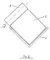
In Figur 2 ist ein Querschnitt durch den in Figur 1 dargestellten Tauchfroster gezeigt. In dieser Darstellung wird die V-förmige Ausbildung des Troges 1 deutlich. Die Trogwände können auf einfache Weise durch Umbiegen eines Bleches gefertigt werden. Am oberen Rand einer Trogwand ist eine Umlenkrolle 3 so angeordnet, daß ihre Drehachse parallel zur Flächennormale dieser Trogwand gerichtet ist. Mittels der Umlenkrollen 3 wird ein im Querschnitt nicht darstellbares Gurtband senkrecht zur Blattebene, d.h. parallel zur Längsrichtung des Troges geführt. An dem Gurtband sind plattenförmig ausgebildete Räumelemente 5 befestigt, deren Kanten parallel zu den Trogwänden des Troges 1 gerichtet sind.FIG. 2 shows a cross section through the immersion freezer shown in FIG. 1. In this illustration, the V-shaped design of the trough 1 is clear. The trough walls can be manufactured in a simple manner by bending a sheet. At the upper edge of a trough wall, a
Claims (13)
Applications Claiming Priority (2)
| Application Number | Priority Date | Filing Date | Title |
|---|---|---|---|
| DE4232641A DE4232641A1 (en) | 1992-09-29 | 1992-09-29 | Device for tempering objects |
| DE4232641 | 1992-09-29 |
Publications (2)
| Publication Number | Publication Date |
|---|---|
| EP0590417A1 true EP0590417A1 (en) | 1994-04-06 |
| EP0590417B1 EP0590417B1 (en) | 1996-03-20 |
Family
ID=6469144
Family Applications (1)
| Application Number | Title | Priority Date | Filing Date |
|---|---|---|---|
| EP93114864A Expired - Lifetime EP0590417B1 (en) | 1992-09-29 | 1993-09-15 | Device for conditioning the temperature of objects |
Country Status (3)
| Country | Link |
|---|---|
| EP (1) | EP0590417B1 (en) |
| DE (2) | DE4232641A1 (en) |
| ES (1) | ES2085087T3 (en) |
Cited By (3)
| Publication number | Priority date | Publication date | Assignee | Title |
|---|---|---|---|---|
| FR2793005A1 (en) * | 1999-04-27 | 2000-11-03 | Air Liquide | Freezing food product involves using cryogenic fluid as product moves through chamber with location(s) where surface of product in contact with product support changes |
| FR3110562A1 (en) * | 2020-05-20 | 2021-11-26 | Tremark | Feeder for packaging food compositions |
| EP4183722A1 (en) * | 2021-11-18 | 2023-05-24 | Tremark France | Feeder for packaging food compositions |
Citations (9)
| Publication number | Priority date | Publication date | Assignee | Title |
|---|---|---|---|---|
| US2774460A (en) * | 1953-03-16 | 1956-12-18 | Lewis Refrigeration & Supply C | Quick-freeze conveyors |
| US3004407A (en) * | 1960-04-19 | 1961-10-17 | Morris And Associates Inc | Continuous poultry chiller apparatus and method |
| US3114248A (en) * | 1961-10-20 | 1963-12-17 | Willard L Morrison | Method and apparatus for freezing hot cooked food |
| US3376710A (en) * | 1966-05-16 | 1968-04-09 | Hirtensteiner Walter Earl | Food freezing apparatus |
| GB1226056A (en) * | 1968-07-15 | 1971-03-24 | ||
| DE2228564A1 (en) * | 1972-06-12 | 1974-01-10 | Ascobloc Veb K | DEVICE FOR CONTINUOUS COOKING, COOKING AND STEAMING OR REFRIGERATING FOOD |
| GB1557886A (en) * | 1977-09-19 | 1979-12-12 | Cope Whelon & Co Ltd | Chilling apparatus |
| US4479363A (en) * | 1983-02-10 | 1984-10-30 | The Boc Group Plc | Freezing a liquid |
| US4788831A (en) * | 1987-09-08 | 1988-12-06 | Simon-Johnson, Inc. | Method and apparatus for loading poultry carcasses into drag type positive control chiller |
-
1992
- 1992-09-29 DE DE4232641A patent/DE4232641A1/en not_active Withdrawn
-
1993
- 1993-09-15 EP EP93114864A patent/EP0590417B1/en not_active Expired - Lifetime
- 1993-09-15 ES ES93114864T patent/ES2085087T3/en not_active Expired - Lifetime
- 1993-09-15 DE DE59301949T patent/DE59301949D1/en not_active Expired - Fee Related
Patent Citations (9)
| Publication number | Priority date | Publication date | Assignee | Title |
|---|---|---|---|---|
| US2774460A (en) * | 1953-03-16 | 1956-12-18 | Lewis Refrigeration & Supply C | Quick-freeze conveyors |
| US3004407A (en) * | 1960-04-19 | 1961-10-17 | Morris And Associates Inc | Continuous poultry chiller apparatus and method |
| US3114248A (en) * | 1961-10-20 | 1963-12-17 | Willard L Morrison | Method and apparatus for freezing hot cooked food |
| US3376710A (en) * | 1966-05-16 | 1968-04-09 | Hirtensteiner Walter Earl | Food freezing apparatus |
| GB1226056A (en) * | 1968-07-15 | 1971-03-24 | ||
| DE2228564A1 (en) * | 1972-06-12 | 1974-01-10 | Ascobloc Veb K | DEVICE FOR CONTINUOUS COOKING, COOKING AND STEAMING OR REFRIGERATING FOOD |
| GB1557886A (en) * | 1977-09-19 | 1979-12-12 | Cope Whelon & Co Ltd | Chilling apparatus |
| US4479363A (en) * | 1983-02-10 | 1984-10-30 | The Boc Group Plc | Freezing a liquid |
| US4788831A (en) * | 1987-09-08 | 1988-12-06 | Simon-Johnson, Inc. | Method and apparatus for loading poultry carcasses into drag type positive control chiller |
Cited By (3)
| Publication number | Priority date | Publication date | Assignee | Title |
|---|---|---|---|---|
| FR2793005A1 (en) * | 1999-04-27 | 2000-11-03 | Air Liquide | Freezing food product involves using cryogenic fluid as product moves through chamber with location(s) where surface of product in contact with product support changes |
| FR3110562A1 (en) * | 2020-05-20 | 2021-11-26 | Tremark | Feeder for packaging food compositions |
| EP4183722A1 (en) * | 2021-11-18 | 2023-05-24 | Tremark France | Feeder for packaging food compositions |
Also Published As
| Publication number | Publication date |
|---|---|
| DE59301949D1 (en) | 1996-04-25 |
| EP0590417B1 (en) | 1996-03-20 |
| DE4232641A1 (en) | 1994-03-31 |
| ES2085087T3 (en) | 1996-05-16 |
Similar Documents
| Publication | Publication Date | Title |
|---|---|---|
| DE2410392C2 (en) | Conveyor | |
| DE2655381A1 (en) | DEVICE ON SCREW CONVEYORS | |
| DE2149633A1 (en) | Freezer | |
| EP0590417B1 (en) | Device for conditioning the temperature of objects | |
| DE2242732C3 (en) | Device for the continuous pasteurization of food or pharmaceuticals contained in bags | |
| DE1607072A1 (en) | Feed return device | |
| EP0565000B1 (en) | Method and device for supplying and clearing a buffer conveyor | |
| DE2618911A1 (en) | Bunker for granular ice - has conveying worms above bottom section discharging ice through openings in wall | |
| EP0222063B1 (en) | Device for releasing out bulk material from a stockpole | |
| DE2610658C3 (en) | Silo system, especially for clay and clay-like masses | |
| DE3345374A1 (en) | DEVICE FOR CLEANING TUB-SHAPED CONTAINERS | |
| DE3304616C2 (en) | ||
| DE2040568B2 (en) | Device, in particular a sterilizer, for conveying containers with sterilizable contents | |
| DE2324329A1 (en) | Immersion cooking of foodstuffs - with endless belt conveying down then up from inlet to outlet | |
| EP0698365B1 (en) | Plant for grilling spits equipped with grill-good | |
| DE4302962A1 (en) | Discharge device for bulk materials | |
| DE2167250C2 (en) | Device for transporting pasta | |
| DE3212877C2 (en) | Device for making bread | |
| DE3717748C1 (en) | Plate heat exchanger for preheating broken glass or similar bulk materials | |
| CH465486A (en) | Process for the continuous packaging of piece goods in individual compartments of containers | |
| DE2337770A1 (en) | Hygienic conveyor for hot juices containers - with easy access, corrosion resistant components and no dust traps | |
| DE1233778B (en) | Conveyor device | |
| DE8104419U1 (en) | SCRATCH CONVEYOR FOR HOT CONVEYOR | |
| DE1429979A1 (en) | Continuous roasting machine | |
| DD245942B1 (en) | DEVICE FOR REMOVING ASHES FROM BOILER |
Legal Events
| Date | Code | Title | Description |
|---|---|---|---|
| PUAI | Public reference made under article 153(3) epc to a published international application that has entered the european phase |
Free format text: ORIGINAL CODE: 0009012 |
|
| AK | Designated contracting states |
Kind code of ref document: A1 Designated state(s): BE DE ES FR GB IT |
|
| 17P | Request for examination filed |
Effective date: 19940414 |
|
| 17Q | First examination report despatched |
Effective date: 19941125 |
|
| GRAA | (expected) grant |
Free format text: ORIGINAL CODE: 0009210 |
|
| AK | Designated contracting states |
Kind code of ref document: B1 Designated state(s): BE DE ES FR GB IT |
|
| PG25 | Lapsed in a contracting state [announced via postgrant information from national office to epo] |
Ref country code: GB Effective date: 19960320 Ref country code: BE Effective date: 19960320 |
|
| ITF | It: translation for a ep patent filed |
Owner name: JACOBACCI & PERANI S.P.A. |
|
| ET | Fr: translation filed | ||
| REF | Corresponds to: |
Ref document number: 59301949 Country of ref document: DE Date of ref document: 19960425 |
|
| REG | Reference to a national code |
Ref country code: ES Ref legal event code: FG2A Ref document number: 2085087 Country of ref document: ES Kind code of ref document: T3 |
|
| PGFP | Annual fee paid to national office [announced via postgrant information from national office to epo] |
Ref country code: FR Payment date: 19960910 Year of fee payment: 4 |
|
| GBV | Gb: ep patent (uk) treated as always having been void in accordance with gb section 77(7)/1977 [no translation filed] |
Effective date: 19960320 |
|
| PLBE | No opposition filed within time limit |
Free format text: ORIGINAL CODE: 0009261 |
|
| STAA | Information on the status of an ep patent application or granted ep patent |
Free format text: STATUS: NO OPPOSITION FILED WITHIN TIME LIMIT |
|
| 26N | No opposition filed | ||
| PGFP | Annual fee paid to national office [announced via postgrant information from national office to epo] |
Ref country code: ES Payment date: 19970926 Year of fee payment: 5 |
|
| PG25 | Lapsed in a contracting state [announced via postgrant information from national office to epo] |
Ref country code: FR Free format text: THE PATENT HAS BEEN ANNULLED BY A DECISION OF A NATIONAL AUTHORITY Effective date: 19970930 |
|
| REG | Reference to a national code |
Ref country code: FR Ref legal event code: ST |
|
| PG25 | Lapsed in a contracting state [announced via postgrant information from national office to epo] |
Ref country code: ES Free format text: LAPSE BECAUSE OF NON-PAYMENT OF DUE FEES Effective date: 19980916 |
|
| PGFP | Annual fee paid to national office [announced via postgrant information from national office to epo] |
Ref country code: DE Payment date: 19980923 Year of fee payment: 6 |
|
| PG25 | Lapsed in a contracting state [announced via postgrant information from national office to epo] |
Ref country code: DE Free format text: LAPSE BECAUSE OF NON-PAYMENT OF DUE FEES Effective date: 20000701 |
|
| REG | Reference to a national code |
Ref country code: ES Ref legal event code: FD2A Effective date: 19991013 |
|
| PG25 | Lapsed in a contracting state [announced via postgrant information from national office to epo] |
Ref country code: IT Free format text: LAPSE BECAUSE OF NON-PAYMENT OF DUE FEES;WARNING: LAPSES OF ITALIAN PATENTS WITH EFFECTIVE DATE BEFORE 2007 MAY HAVE OCCURRED AT ANY TIME BEFORE 2007. THE CORRECT EFFECTIVE DATE MAY BE DIFFERENT FROM THE ONE RECORDED. Effective date: 20050915 |