EP0587514A1 - Processor module for video inspection probe - Google Patents
Processor module for video inspection probe Download PDFInfo
- Publication number
- EP0587514A1 EP0587514A1 EP93420360A EP93420360A EP0587514A1 EP 0587514 A1 EP0587514 A1 EP 0587514A1 EP 93420360 A EP93420360 A EP 93420360A EP 93420360 A EP93420360 A EP 93420360A EP 0587514 A1 EP0587514 A1 EP 0587514A1
- Authority
- EP
- European Patent Office
- Prior art keywords
- video
- module
- circuitry
- inspection probe
- probe
- Prior art date
- Legal status (The legal status is an assumption and is not a legal conclusion. Google has not performed a legal analysis and makes no representation as to the accuracy of the status listed.)
- Ceased
Links
Images


Classifications
-
- A—HUMAN NECESSITIES
- A61—MEDICAL OR VETERINARY SCIENCE; HYGIENE
- A61B—DIAGNOSIS; SURGERY; IDENTIFICATION
- A61B1/00—Instruments for performing medical examinations of the interior of cavities or tubes of the body by visual or photographical inspection, e.g. endoscopes; Illuminating arrangements therefor
- A61B1/04—Instruments for performing medical examinations of the interior of cavities or tubes of the body by visual or photographical inspection, e.g. endoscopes; Illuminating arrangements therefor combined with photographic or television appliances
- A61B1/05—Instruments for performing medical examinations of the interior of cavities or tubes of the body by visual or photographical inspection, e.g. endoscopes; Illuminating arrangements therefor combined with photographic or television appliances characterised by the image sensor, e.g. camera, being in the distal end portion
-
- A—HUMAN NECESSITIES
- A61—MEDICAL OR VETERINARY SCIENCE; HYGIENE
- A61B—DIAGNOSIS; SURGERY; IDENTIFICATION
- A61B1/00—Instruments for performing medical examinations of the interior of cavities or tubes of the body by visual or photographical inspection, e.g. endoscopes; Illuminating arrangements therefor
- A61B1/04—Instruments for performing medical examinations of the interior of cavities or tubes of the body by visual or photographical inspection, e.g. endoscopes; Illuminating arrangements therefor combined with photographic or television appliances
Definitions
- This invention relates to inspection devices, such as a borescope or endoscope, of the type in which a miniature video camera is mounted at a distal viewing head of an elongated insertion tube.
- the invention is more particularly concerned with an improved plug-in connector module for coupling the probe to a light and power source, and which contains all the circuitry necessary to process the output of the miniature video camera and deliver a video signal suitable to apply directly to a video monitor.
- the probe system prefferably be compact and to operate at low power consumption rates, for example, so that the unit can be compact and of light weight, and also so that the unit can be made battery powered and portable.
- a video laparoscope with a light source based on small, low-power metal halide discharge lamp is described in copending patent application Ser. No. 07/780,762, filed October 22, 1991, and having a common assignee.
- a laparoscope or other similar probe has a miniature video camera that incorporates a miniature electronic imager and a lens assembly which are disposed either at the distal tip or at a proximal end of a flexible or rigid insertion tube.
- the camera can be distally mounted.
- the camera can be proximally mounted, with a relay lens system being contained in the insertion tube.
- the insertion tube can be rigid or can have its tip portion articulatable.
- the small video camera can be incorporated in an add-on camera attachment for laparoscopes having a proximal viewing port.
- Disposing the camera at the distal tip of the laparoscope insertion tube reduces the amount of focussing and relay lenses to be carried in the tube. This means less light is lost in the lens system, so the amount of optical fiber bundle needed for illumination, is reduced which also permits the insertion tube to be made smaller.
- the insertion tube proximal end is coupled through a flexible cable or umbilical to a connector module that plugs into a socket in a processor unit.
- a video cable that extends through the insertion tube and umbilical has terminals in the connector module that supply the video signal from the miniature camera to electronic circuitry in the processor, which supplies a suitable signal to a full color or monochrome monitor.
- An image of a target area such as a tissue within a patient's body cavity, can be viewed on the monitor.
- a high illuminance, but low-wattage light source in the form of one or more metal halide discharge lamps.
- These can preferably be of the type described in copending Patent Application Ser. Nos. 07/484,166, filed February 23, 1990; 07/636,743, 07/636,743, and 07/636,744, each filed December 31, 1990, and which have an assignee in common herewith.
- the lamp typically operates at a power of about 20 watts dc, and has an efficacy of at least 35 lumens per watt.
- the light produced which can be controlled by the selection of salts employed, the dosage of mercury, and mechanical structure of the lamps, has an emission spectrum in the visible band, with very little radiation produced in the infrared band.
- the arc gap of this lamp is small, which produces a small spot of light when focused onto the fiber optic bundle used for illumination.
- the small spot size allows almost all the light energy to be directed into the proximal end of a very small fiber bundle.
- the smaller illumination bundle permits the insertion tube to be made much smaller than was previously possible while still delivering plenty of light to the target area.
- the probe can incorporate redundant optical fiber bundles, which can each be associated with a respective light source.
- the lamp operates at low power (e.g. 20 watts), producing limited infrared radiation, and with virtually all the light being focused onto the fiber optic bundle, the light source can be made much more compact, and the lamp power supply can be much smaller.
- the light incident on the target consists substantially only of visible light, with very little radiant heat. This permits the operator to view and examine living tissues or other delicate target materials for extended intervals without danger of tissue damage or the ignition of surgical drapes.
- a laparoscope, endoscope, borescope, or other similar probe has a miniature video camera associated with the insertion tube.
- the camera incorporates a miniature electronic imager and a lens assembly.
- a fiber optic bundle carries light for illuminating the target and emits light from the distal end of the probe.
- a plug-in module contains the required video processing electronics within a sealed housing.
- the electronics receives power from a connector mounted on the housing, sends to the camera suitable control and synchronizing signals, and receives and processes image signals that represent the image of the target.
- a video signal is provided to output terminals on the connector.
- the video signal can be directly fed to a suitable video monitor to provide a picture display of the target as viewed by the miniature camera.
- the illumination fiber optic bundle can be one bundle, or can be bifurcated so that it can receive light from two separate light sources.
- the bundle extends proximally from the proximal face of the module, and is supported in a projecting metal sleeve which serves to locate the end of the fiber bundle at the focus of the associated light source.
- the module is profiled, in cross section, so that it fits insertably into a suitably profiled socket on a power and light unit.
- There is a power supply that provides power for the video circuity to a mating connector within the socket, so that power is supplied to the connector on the module and also brings off the video signal is brought off when the module is positioned in the socket.
- Fig. 1 is a perspective view of a probe assembly according to one of many possible embodiments of this invention.
- Fig. 2 is a perspective view of a video processor module according to this embodiment of the invention.
- Figs. 3 and 4 are top plan view of the video processor module showing progressive stages of assembly.
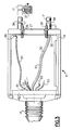
- Fig. 5 is schematic sectional view of a light and power unit of this invention.
- a borescope assembly 10 has an elongated, narrow insertion tube 11 having a distal tip 12 and a control handle 13 located at its proximal end. Wires, cables, and fiber optic bundles pass from the distal tip 12 through the insertion tube 11 and handle 13 and from there through a flexible tubular umbilical 14.
- the umbilical 14 is joined by a strain relief to a sealed plug-in processing module 15.
- the module 15 has a sealed casing or housing 16 with protruding tubes or sleeves 17 that project from its proximal face.
- the processor module 15 serves as a connector module and plugs into a socket 18 on the front panel 19 of the cabinet of an associated light and power unit 20.
- the front panel 19 has associated controls and displays 21.
- a video monitor 22 which can be a color or black-and-white CRT, or can possibly be a projecting screen device or an LCD monitor, is coupled by a suitable cable 23 to the unit 20.
- the latter has a suitable wiring harness therein to connect the monitor 22 to the module 15.
- a miniature video camera 24 contains focusing lenses and a small solid-state imager, and is disposed in the distal tip 12 of the insertion tube 11.
- Projecting ribs 25 on opposite side walls of the casing 16 serve as keys for fitting into mating recesses 26 in the sides of the socket 18.
- the ribs are positioned somewhat asymmetrically so that the module 15 cannot be inadvertently installed upside down.
- a multi-pin electrical connector 27 disposed on the proximal wall of the module 15.
- This connector 27 includes several contact pins to bring power into the module and other pins which deliver a processed video signal that can be carried by the wiring harness and the cable 23 to the monitor 22.
- a fiber optic bundle 30 for carrying illumination to the distal end of the insertion tube 11 has a proximal end 32 disposed in one of the tubular sleeves 17.
- This sleeve 17 serves to position the proximal end 32 in position to receive light from a light source.
- a grounding strap or pigtail 34 unites a ground conductor 35 in the umbilical to a grounding plate 36 disposed on the proximal side of the housing, and which is in electrical contact with each of the two sleeves 17.
- a retaining detente 37 within the unit 20 and which is electrically connected to chassis ground within the light and power unit 20.
- the detente 37 mechanically engages an annular recess 38 in the respective sleeve 17. This both couples the ground of the module 15 to the chassis ground of the unit 20, and also positions the fiber optic bundle end 32 accurately with respect to light sources to be described later.
- one or more printed circuit boards 40 disposed within the module housing 16 contains electronics which derive power from certain ones of the contact pins of the connector 27, and the electronics also provide a processed video signal to other pins of this connector 27.
- the video processing circuitry also provides synchronizing and control signals over the conductors 33 to the miniature camera 24.
- the circuitry on the board or boards 40 receives the image signal from the camera, and processes the same to produce a suitable video signal in a desired standard format, e.g. NTSC, PAL, SECAM, etc, so that it can be applied directly to the video monitor 22.
- a desired standard format e.g. NTSC, PAL, SECAM, etc.
- each video camera 24 is matched with its own video circuitry contained within the module 15.
- each probe unit is entirely modular, that is, completely interchangeable so that modular borescopes, endoscopes, or laparoscopes of different types can be employed using a single light and power unit 20.
- any individual probe unit 10 can be used with any of various similar light and power units 20.
- the processing circuitry (40) can be switched electrically from an NTSC output to a PAL or SECAM output so that the probe can be fitted to a monitor universally.
- the probe unit 10 is entirely sealed, and can be completely immersed in ethylene oxide or another sterilization agent for sterilization between uses.
- the circuit board or boards 40 is environmentally sealed within the housing.
- a lamp assembly 50 within the cabinet of the unit 20 and located behind the socket 18, there is a lamp assembly 50.
- an associated ballast 54 Positioned above the lamp and reflection is an associated ballast 54, i.e., a power supply for the lamp.
- a power supply 55 which provides appropriate electrical current to the lamp ballast 54, and also provides the various required dc levels, through the coupler 27, to the electrical circuitry within the module 15.
- the discharge lamp 52 is a low-wattage unit (e.g. 20 watts) containing suitable halide salts to emit white light, i.e. comprised of red, green and blue wavelengths, but without appreciable amounts of infrared radiation.
- the lamp has a very small arc gap so as to constitute a point source, whereby the reflected spot at its second focus is quite small.
- a mating electrical connector (obscured in this view) which mates with the coupler 27 when the module 15 is completely inserted into the socket 18.
- Receptacles 48 are situated within the socket to receive and to locate the sleeves 17. These ensure that the fiber optic bundle end 32 is positioned at a location to receive the focussed spot of light from the lamp assembly 50.
Abstract
A plug-in module (15) for a video probe has a housing (16) which contains video processing circuitry (40) to receive a video output from a miniature video imager and produces a video signal suitable to apply, without further processing, to a video monitor (22). The module plugs (15) into a mating socket (18) of a power and illumination unit (20). A fiber optic bundle extends into a sleeve (17) protruding from a proximal face of the module (15), and is positioned at the focus of a small, high efficacy lamp assembly. The housing (16) of the plug-in module environmentally seals the electronic circuitry (40), and is permanently attached onto a tubular umbilical (14) of the video probe.
Description
- This invention relates to inspection devices, such as a borescope or endoscope, of the type in which a miniature video camera is mounted at a distal viewing head of an elongated insertion tube. The invention is more particularly concerned with an improved plug-in connector module for coupling the probe to a light and power source, and which contains all the circuitry necessary to process the output of the miniature video camera and deliver a video signal suitable to apply directly to a video monitor.
- It is desirable for the probe system to be compact and to operate at low power consumption rates, for example, so that the unit can be compact and of light weight, and also so that the unit can be made battery powered and portable.
- A video laparoscope with a light source based on small, low-power metal halide discharge lamp is described in copending patent application Ser. No. 07/780,762, filed October 22, 1991, and having a common assignee. As described in that patent application, a laparoscope or other similar probe has a miniature video camera that incorporates a miniature electronic imager and a lens assembly which are disposed either at the distal tip or at a proximal end of a flexible or rigid insertion tube. For insertion tubes of about 5 mm or larger, the camera can be distally mounted. For very slim insertion tubes, the camera can be proximally mounted, with a relay lens system being contained in the insertion tube. The insertion tube can be rigid or can have its tip portion articulatable. The small video camera can be incorporated in an add-on camera attachment for laparoscopes having a proximal viewing port.
- Disposing the camera at the distal tip of the laparoscope insertion tube reduces the amount of focussing and relay lenses to be carried in the tube. This means less light is lost in the lens system, so the amount of optical fiber bundle needed for illumination, is reduced which also permits the insertion tube to be made smaller.
- The insertion tube proximal end is coupled through a flexible cable or umbilical to a connector module that plugs into a socket in a processor unit. A video cable that extends through the insertion tube and umbilical has terminals in the connector module that supply the video signal from the miniature camera to electronic circuitry in the processor, which supplies a suitable signal to a full color or monochrome monitor. An image of a target area, such as a tissue within a patient's body cavity, can be viewed on the monitor.
- Also within the processor is a high illuminance, but low-wattage light source in the form of one or more metal halide discharge lamps. These can preferably be of the type described in copending Patent Application Ser. Nos. 07/484,166, filed February 23, 1990; 07/636,743, 07/636,743, and 07/636,744, each filed December 31, 1990, and which have an assignee in common herewith. The lamp typically operates at a power of about 20 watts dc, and has an efficacy of at least 35 lumens per watt. The light produced, which can be controlled by the selection of salts employed, the dosage of mercury, and mechanical structure of the lamps, has an emission spectrum in the visible band, with very little radiation produced in the infrared band. Also, the arc gap of this lamp is small, which produces a small spot of light when focused onto the fiber optic bundle used for illumination. The small spot size allows almost all the light energy to be directed into the proximal end of a very small fiber bundle. The smaller illumination bundle permits the insertion tube to be made much smaller than was previously possible while still delivering plenty of light to the target area. Also, because small optical fiber bundles can be used, the probe can incorporate redundant optical fiber bundles, which can each be associated with a respective light source. Moreover, because the lamp operates at low power (e.g. 20 watts), producing limited infrared radiation, and with virtually all the light being focused onto the fiber optic bundle, the light source can be made much more compact, and the lamp power supply can be much smaller. The light incident on the target consists substantially only of visible light, with very little radiant heat. This permits the operator to view and examine living tissues or other delicate target materials for extended intervals without danger of tissue damage or the ignition of surgical drapes.
- It is an object of this invention to provide an improved inspection probe that avoids the problems of the prior art.
- It is another object to provide a video probe which has a self-contained plug-in video module containing the electronics for operating and delivering a video signal based on an image signal from the miniature video imager in the insertion tube.
- In accordance with an aspect of this invention, a laparoscope, endoscope, borescope, or other similar probe has a miniature video camera associated with the insertion tube. The camera incorporates a miniature electronic imager and a lens assembly. A fiber optic bundle carries light for illuminating the target and emits light from the distal end of the probe.
- A plug-in module contains the required video processing electronics within a sealed housing. The electronics receives power from a connector mounted on the housing, sends to the camera suitable control and synchronizing signals, and receives and processes image signals that represent the image of the target. From the electronics contained in the module, a video signal is provided to output terminals on the connector. The video signal can be directly fed to a suitable video monitor to provide a picture display of the target as viewed by the miniature camera. The illumination fiber optic bundle can be one bundle, or can be bifurcated so that it can receive light from two separate light sources. The bundle extends proximally from the proximal face of the module, and is supported in a projecting metal sleeve which serves to locate the end of the fiber bundle at the focus of the associated light source.
- The module is profiled, in cross section, so that it fits insertably into a suitably profiled socket on a power and light unit. There is a power supply that provides power for the video circuity to a mating connector within the socket, so that power is supplied to the connector on the module and also brings off the video signal is brought off when the module is positioned in the socket.
- The above and many other objects, features, and advantages of this invention will become apparent to those skilled in the art from the ensuing description of an exemplary embodiment of this invention, to be read in conjunction with the accompanying Drawing.
- Fig. 1 is a perspective view of a probe assembly according to one of many possible embodiments of this invention.
- Fig. 2 is a perspective view of a video processor module according to this embodiment of the invention.
- Figs. 3 and 4 are top plan view of the video processor module showing progressive stages of assembly.
- Fig. 5 is schematic sectional view of a light and power unit of this invention.
- With reference to the Drawing, and initially to Fig. 1, a
borescope assembly 10 according to one embodiment of the present invention has an elongated, narrow insertion tube 11 having adistal tip 12 and acontrol handle 13 located at its proximal end. Wires, cables, and fiber optic bundles pass from thedistal tip 12 through the insertion tube 11 and handle 13 and from there through a flexible tubular umbilical 14. The umbilical 14 is joined by a strain relief to a sealed plug-inprocessing module 15. Themodule 15 has a sealed casing orhousing 16 with protruding tubes orsleeves 17 that project from its proximal face. Theprocessor module 15 serves as a connector module and plugs into asocket 18 on thefront panel 19 of the cabinet of an associated light andpower unit 20. Thefront panel 19 has associated controls and displays 21. Avideo monitor 22, which can be a color or black-and-white CRT, or can possibly be a projecting screen device or an LCD monitor, is coupled by asuitable cable 23 to theunit 20. The latter has a suitable wiring harness therein to connect themonitor 22 to themodule 15. Aminiature video camera 24 contains focusing lenses and a small solid-state imager, and is disposed in thedistal tip 12 of the insertion tube 11. - Projecting
ribs 25 on opposite side walls of thecasing 16 serve as keys for fitting intomating recesses 26 in the sides of thesocket 18. The ribs are positioned somewhat asymmetrically so that themodule 15 cannot be inadvertently installed upside down. - As shown in Fig. 2, there is a multi-pin
electrical connector 27 disposed on the proximal wall of themodule 15. Thisconnector 27 includes several contact pins to bring power into the module and other pins which deliver a processed video signal that can be carried by the wiring harness and thecable 23 to themonitor 22. There are also a pair of locating pins orstuds 28 disposed one on each side of theconnector 27. These serve to locate or position the connector within thesocket 18 when theprocessor module 15 is installed into the socket. - As shown in Fig. 3, in this case a fiber
optic bundle 30 for carrying illumination to the distal end of the insertion tube 11 has aproximal end 32 disposed in one of thetubular sleeves 17. Thissleeve 17 serves to position theproximal end 32 in position to receive light from a light source. - Also shown here are signal and
control wires 33 which extend from themodule 15, through the umbilical 14 and the insertion tube 11, to thecamera 24. A grounding strap orpigtail 34 unites aground conductor 35 in the umbilical to agrounding plate 36 disposed on the proximal side of the housing, and which is in electrical contact with each of the twosleeves 17. - Also shown here there is a retaining
detente 37 within theunit 20 and which is electrically connected to chassis ground within the light andpower unit 20. Thedetente 37 mechanically engages anannular recess 38 in therespective sleeve 17. This both couples the ground of themodule 15 to the chassis ground of theunit 20, and also positions the fiberoptic bundle end 32 accurately with respect to light sources to be described later. - As shown in Fig. 4, one or more printed
circuit boards 40 disposed within themodule housing 16 contains electronics which derive power from certain ones of the contact pins of theconnector 27, and the electronics also provide a processed video signal to other pins of thisconnector 27. - The video processing circuitry also provides synchronizing and control signals over the
conductors 33 to theminiature camera 24. The circuitry on the board orboards 40 receives the image signal from the camera, and processes the same to produce a suitable video signal in a desired standard format, e.g. NTSC, PAL, SECAM, etc, so that it can be applied directly to thevideo monitor 22. With this arrangement, eachvideo camera 24 is matched with its own video circuitry contained within themodule 15. This means that each probe unit is entirely modular, that is, completely interchangeable so that modular borescopes, endoscopes, or laparoscopes of different types can be employed using a single light andpower unit 20. Also, anyindividual probe unit 10 can be used with any of various similar light andpower units 20. In an optional configuration, the processing circuitry (40) can be switched electrically from an NTSC output to a PAL or SECAM output so that the probe can be fitted to a monitor universally. - The
probe unit 10 is entirely sealed, and can be completely immersed in ethylene oxide or another sterilization agent for sterilization between uses. The circuit board orboards 40 is environmentally sealed within the housing. - As shown in Fig. 5, within the cabinet of the
unit 20 and located behind thesocket 18, there is alamp assembly 50. This includes a low power metalhalide discharge lamp 52 and anelliptical reflector 53, with thelamp 52 positioned at a first focus of the reflector. Positioned above the lamp and reflection is an associatedballast 54, i.e., a power supply for the lamp. Also within the cabinet is apower supply 55, which provides appropriate electrical current to thelamp ballast 54, and also provides the various required dc levels, through thecoupler 27, to the electrical circuitry within themodule 15. - The
discharge lamp 52 is a low-wattage unit (e.g. 20 watts) containing suitable halide salts to emit white light, i.e. comprised of red, green and blue wavelengths, but without appreciable amounts of infrared radiation. The lamp has a very small arc gap so as to constitute a point source, whereby the reflected spot at its second focus is quite small. - Also within the
socket 18 is a mating electrical connector (obscured in this view) which mates with thecoupler 27 when themodule 15 is completely inserted into thesocket 18.Receptacles 48 are situated within the socket to receive and to locate thesleeves 17. These ensure that the fiberoptic bundle end 32 is positioned at a location to receive the focussed spot of light from thelamp assembly 50. - While this invention has been described in detail with respect to a selected embodiment, it should be understood that the invention is not limited to that precise embodiment. Instead, many modifications and variations would present themselves to those of skill in the art without departing from the scope and spirit of this invention, as defined in the appended claims.
Claims (6)
- A video inspection probe in which a visual image of a remote target is reproduced on a video monitor (22), a lens focusses the image of the target onto a solid state imager (24) which provides a video output for applying to said video monitor (22), a probe tube (11) carries said lens and said imager, and a processor module (15) affixed onto a proximal end (14) of said probe tube means including a module housing (16) that contains circuitry (40) therewithin, and an electric coupler (27) carried on said housing (16) has electric power contacts on which power is received, and output contacts; characterized in that said circuitry (40) contained within said module housing (16) includes a video processor circuit coupled to said imager to receive and process a raw video output furnished by said imager and supply to respective contacts on said coupler (27) a standard-format processed video signal that is ready to be supplied without additional processing to said monitor (22).
- The video inspection probe of claim 1 characterized in that said housing (16) has a profile in cross section which is oblong, and one or more protruding ribs (25) for fitting into a mating recess (18) of a power and illumination unit (20), the recess (18) having a similar oblong profile with a corresponding one or more cutouts (26) to receive said ribs.
- The video inspection probe of claim 1 characterized in that said circuitry (40) contained within said module housing (16) provides said video output signal in an NTSC format.
- The video inspection probe of claim 1 characterized in that said circuitry (40) contained within said module housing (16) provides said video output signal in a PAL format.
- The video inspection probe of claim 1 characterized in that said circuitry (40) contained within said module housing (16) provides said video output signal in a SECAM format.
- The video inspection probe of claim 3, 4 or 5 characterized in that said circuitry (40) can be electrically switched to switch over said output signal between one and another of the NTSC, PAL and SECAM formats.
Applications Claiming Priority (2)
| Application Number | Priority Date | Filing Date | Title |
|---|---|---|---|
| US94412992A | 1992-09-11 | 1992-09-11 | |
| US944129 | 1992-09-11 |
Publications (1)
| Publication Number | Publication Date |
|---|---|
| EP0587514A1 true EP0587514A1 (en) | 1994-03-16 |
Family
ID=25480841
Family Applications (1)
| Application Number | Title | Priority Date | Filing Date |
|---|---|---|---|
| EP93420360A Ceased EP0587514A1 (en) | 1992-09-11 | 1993-09-07 | Processor module for video inspection probe |
Country Status (4)
| Country | Link |
|---|---|
| US (1) | US5701155A (en) |
| EP (1) | EP0587514A1 (en) |
| JP (1) | JPH06165753A (en) |
| CA (1) | CA2105757A1 (en) |
Cited By (4)
| Publication number | Priority date | Publication date | Assignee | Title |
|---|---|---|---|---|
| EP1054284A1 (en) * | 1999-05-21 | 2000-11-22 | Renault | Vision device with digital micro-camera |
| US6315712B1 (en) | 1998-10-27 | 2001-11-13 | Tokendo (Sarl) | Video endoscopic probe with a distal color CCD sensor |
| FR2850823A1 (en) * | 2003-01-31 | 2004-08-06 | Tokendo | Video endoscope for observing target, has visualization case that is integrated to lateral face of control case by articulation formed by connector, where control case is elongated between distal and proximal ends of inspection tube |
| US7074182B2 (en) | 2003-01-17 | 2006-07-11 | Tokendo | Videoendoscope |
Families Citing this family (124)
| Publication number | Priority date | Publication date | Assignee | Title |
|---|---|---|---|---|
| US6043839A (en) | 1997-10-06 | 2000-03-28 | Adair; Edwin L. | Reduced area imaging devices |
| US5929901A (en) * | 1997-10-06 | 1999-07-27 | Adair; Edwin L. | Reduced area imaging devices incorporated within surgical instruments |
| US20110034769A1 (en) * | 1997-10-06 | 2011-02-10 | Micro-Imaging Solutions Llc | Reduced area imaging device incorporated within wireless endoscopic devices |
| US7030904B2 (en) * | 1997-10-06 | 2006-04-18 | Micro-Medical Devices, Inc. | Reduced area imaging device incorporated within wireless endoscopic devices |
| US6424369B1 (en) | 1997-10-06 | 2002-07-23 | Edwin L. Adair | Hand-held computers incorporating reduced area imaging devices |
| US6452626B1 (en) | 1997-10-06 | 2002-09-17 | Edwin L. Adair | Communication devices incorporating reduced area imaging devices |
| US7002621B2 (en) * | 1997-10-06 | 2006-02-21 | Adair Edwin L | Communication devices incorporating reduced area imaging devices |
| US6982742B2 (en) * | 1997-10-06 | 2006-01-03 | Adair Edwin L | Hand-held computers incorporating reduced area imaging devices |
| US6310642B1 (en) | 1997-11-24 | 2001-10-30 | Micro-Medical Devices, Inc. | Reduced area imaging devices incorporated within surgical instruments |
| US6982740B2 (en) * | 1997-11-24 | 2006-01-03 | Micro-Medical Devices, Inc. | Reduced area imaging devices utilizing selected charge integration periods |
| US6361489B1 (en) | 1998-11-25 | 2002-03-26 | Jory Tsai | Medical inspection device |
| US7137948B2 (en) * | 1998-11-25 | 2006-11-21 | Jory Tsai | Medical inspection device |
| US6186944B1 (en) | 1998-11-25 | 2001-02-13 | Jory Tsai | Medical inspection device |
| US6626825B2 (en) | 1998-11-25 | 2003-09-30 | Jory Tsai | Medical inspection device |
| US7419467B2 (en) * | 1998-11-25 | 2008-09-02 | M3 Electronics, Inc. | Medical inspection device |
| US6958766B2 (en) | 2000-04-06 | 2005-10-25 | Gendex Corporation | Dental video imaging system |
| JP4530498B2 (en) * | 2000-07-25 | 2010-08-25 | オリンパス株式会社 | Endoscope system and light source device for endoscope |
| JP4241038B2 (en) | 2000-10-30 | 2009-03-18 | ザ ジェネラル ホスピタル コーポレーション | Optical method and system for tissue analysis |
| JP2002213561A (en) | 2001-01-23 | 2002-07-31 | Nsk Ltd | Toroidal continuously variable transmission(cvt) |
| US7262797B2 (en) * | 2001-02-22 | 2007-08-28 | Ge Inspection Technologies Lp | Method and system for storing calibration data within image files |
| US7170677B1 (en) | 2002-01-25 | 2007-01-30 | Everest Vit | Stereo-measurement borescope with 3-D viewing |
| US7128709B2 (en) * | 2002-09-11 | 2006-10-31 | Olympus Optical Co., Ltd. | Endoscope apparatus |
| JP2004109222A (en) * | 2002-09-13 | 2004-04-08 | Olympus Corp | Endoscope apparatus |
| US20040183900A1 (en) * | 2003-03-20 | 2004-09-23 | Everest Vit | Method and system for automatically detecting defects in remote video inspection applications |
| US7422559B2 (en) | 2004-06-16 | 2008-09-09 | Ge Inspection Technologies, Lp | Borescope comprising fluid supply system |
| WO2006014392A1 (en) | 2004-07-02 | 2006-02-09 | The General Hospital Corporation | Endoscopic imaging probe comprising dual clad fibre |
| US8208995B2 (en) | 2004-08-24 | 2012-06-26 | The General Hospital Corporation | Method and apparatus for imaging of vessel segments |
| US8083671B2 (en) * | 2004-09-30 | 2011-12-27 | Boston Scientific Scimed, Inc. | Fluid delivery system for use with an endoscope |
| US7597662B2 (en) * | 2004-09-30 | 2009-10-06 | Boston Scientific Scimed, Inc. | Multi-fluid delivery system |
| JP2008521516A (en) | 2004-11-29 | 2008-06-26 | ザ ジェネラル ホスピタル コーポレイション | Configuration, apparatus, endoscope, catheter, and method for performing optical image generation by simultaneously illuminating and detecting multiple points on a sample |
| GB2425424B (en) * | 2005-04-22 | 2010-09-29 | Single Use Surgical Ltd | Disposable flexible endoscope |
| EP2325803A1 (en) | 2005-04-28 | 2011-05-25 | The General Hospital Corporation | Evaluating optical coherence tomography information for an anatomical structure |
| US9060689B2 (en) | 2005-06-01 | 2015-06-23 | The General Hospital Corporation | Apparatus, method and system for performing phase-resolved optical frequency domain imaging |
| US7956888B2 (en) * | 2005-06-22 | 2011-06-07 | Ge Inspection Technologies, Lp | Remote video inspection system integrating audio communication functionality |
| ATE534325T1 (en) | 2005-06-24 | 2011-12-15 | Ge Inspection Technologies Lp | INTRODUCTION TUBE STORAGE CAROUSEL |
| ES2354287T3 (en) | 2005-08-09 | 2011-03-11 | The General Hospital Corporation | APPARATUS AND METHOD FOR PERFORMING A DEMODULATION IN QUADRATURE BY POLARIZATION IN OPTICAL COHERENCE TOMOGRAPHY. |
| CN101365375B (en) | 2005-09-29 | 2013-09-11 | 通用医疗公司 | Method and apparatus for optical imaging via spectral encoding |
| US20070091183A1 (en) * | 2005-10-21 | 2007-04-26 | Ge Inspection Technologies, Lp | Method and apparatus for adapting the operation of a remote viewing device to correct optical misalignment |
| US8145018B2 (en) | 2006-01-19 | 2012-03-27 | The General Hospital Corporation | Apparatus for obtaining information for a structure using spectrally-encoded endoscopy techniques and methods for producing one or more optical arrangements |
| JP5524487B2 (en) | 2006-02-01 | 2014-06-18 | ザ ジェネラル ホスピタル コーポレイション | A method and system for emitting electromagnetic radiation to at least a portion of a sample using a conformal laser treatment procedure. |
| WO2007149603A2 (en) | 2006-02-01 | 2007-12-27 | The General Hospital Corporation | Apparatus for applying a plurality of electro-magnetic radiations to a sample |
| US7679041B2 (en) * | 2006-02-13 | 2010-03-16 | Ge Inspection Technologies, Lp | Electronic imaging device with photosensor arrays |
| EP1987318B1 (en) | 2006-02-24 | 2015-08-12 | The General Hospital Corporation | Methods and systems for performing angle-resolved fourier-domain optical coherence tomography |
| US8368749B2 (en) | 2006-03-27 | 2013-02-05 | Ge Inspection Technologies Lp | Article inspection apparatus |
| EP2517616A3 (en) | 2006-05-10 | 2013-03-06 | The General Hospital Corporation | Processes, arrangements and systems for providing frequency domain imaging of a sample |
| WO2008049118A2 (en) | 2006-10-19 | 2008-04-24 | The General Hospital Corporation | Apparatus and method for obtaining and providing imaging information associated with at least one portion of a sample and effecting such portion(s) |
| US9633426B2 (en) | 2014-05-30 | 2017-04-25 | General Electric Company | Remote visual inspection image capture system and method |
| US8810636B2 (en) | 2006-12-20 | 2014-08-19 | Ge Inspection Technologies, Lp | Inspection apparatus method and apparatus comprising selective frame output |
| US8213676B2 (en) | 2006-12-20 | 2012-07-03 | Ge Inspection Technologies Lp | Inspection apparatus method and apparatus comprising motion responsive control |
| US8118733B2 (en) * | 2006-12-22 | 2012-02-21 | Ge Inspection Technologies, Lp | Heat protection systems and methods for remote viewing devices |
| US8514278B2 (en) | 2006-12-29 | 2013-08-20 | Ge Inspection Technologies Lp | Inspection apparatus having illumination assembly |
| US8625434B2 (en) | 2006-12-29 | 2014-01-07 | Ge Inspection Technologies Lp | IP based voice communication enabled inspection system |
| US8310604B2 (en) | 2007-10-26 | 2012-11-13 | GE Sensing & Inspection Technologies, LP | Visual inspection apparatus having light source bank |
| US8253782B2 (en) | 2007-10-26 | 2012-08-28 | Ge Inspection Technologies, Lp | Integrated storage for industrial inspection handset |
| US8767060B2 (en) * | 2007-10-26 | 2014-07-01 | Ge Inspection Technologies, Lp | Inspection apparatus having heat sink assembly |
| US7902990B2 (en) | 2007-10-26 | 2011-03-08 | Ge Inspection Technologies, Lp | Battery and power management for industrial inspection handset |
| DE202007018570U1 (en) * | 2007-11-09 | 2008-12-04 | Envitec-Wismar Gmbh | Device for measuring the oxygen saturation in the blood |
| WO2010009136A2 (en) | 2008-07-14 | 2010-01-21 | The General Hospital Corporation | Apparatus and methods for color endoscopy |
| US9615748B2 (en) | 2009-01-20 | 2017-04-11 | The General Hospital Corporation | Endoscopic biopsy apparatus, system and method |
| US20100198876A1 (en) | 2009-02-02 | 2010-08-05 | Honeywell International, Inc. | Apparatus and method of embedding meta-data in a captured image |
| CN102308444B (en) | 2009-02-04 | 2014-06-18 | 通用医疗公司 | Apparatus and method for utilization of a high-speed optical wavelength tuning source |
| US9519814B2 (en) | 2009-06-12 | 2016-12-13 | Hand Held Products, Inc. | Portable data terminal |
| US9872609B2 (en) | 2009-06-18 | 2018-01-23 | Endochoice Innovation Center Ltd. | Multi-camera endoscope |
| US9402533B2 (en) | 2011-03-07 | 2016-08-02 | Endochoice Innovation Center Ltd. | Endoscope circuit board assembly |
| US9901244B2 (en) | 2009-06-18 | 2018-02-27 | Endochoice, Inc. | Circuit board assembly of a multiple viewing elements endoscope |
| US11864734B2 (en) | 2009-06-18 | 2024-01-09 | Endochoice, Inc. | Multi-camera endoscope |
| US9101268B2 (en) | 2009-06-18 | 2015-08-11 | Endochoice Innovation Center Ltd. | Multi-camera endoscope |
| US9492063B2 (en) | 2009-06-18 | 2016-11-15 | Endochoice Innovation Center Ltd. | Multi-viewing element endoscope |
| WO2012038958A2 (en) | 2010-09-20 | 2012-03-29 | Peermedical Ltd. | Multi-camera endoscope having fluid channels |
| US9101287B2 (en) | 2011-03-07 | 2015-08-11 | Endochoice Innovation Center Ltd. | Multi camera endoscope assembly having multiple working channels |
| US9642513B2 (en) | 2009-06-18 | 2017-05-09 | Endochoice Inc. | Compact multi-viewing element endoscope system |
| WO2012120507A1 (en) | 2011-02-07 | 2012-09-13 | Peermedical Ltd. | Multi-element cover for a multi-camera endoscope |
| US8926502B2 (en) | 2011-03-07 | 2015-01-06 | Endochoice, Inc. | Multi camera endoscope having a side service channel |
| US9554692B2 (en) | 2009-06-18 | 2017-01-31 | EndoChoice Innovation Ctr. Ltd. | Multi-camera endoscope |
| US9706903B2 (en) | 2009-06-18 | 2017-07-18 | Endochoice, Inc. | Multiple viewing elements endoscope system with modular imaging units |
| US9713417B2 (en) | 2009-06-18 | 2017-07-25 | Endochoice, Inc. | Image capture assembly for use in a multi-viewing elements endoscope |
| US10165929B2 (en) | 2009-06-18 | 2019-01-01 | Endochoice, Inc. | Compact multi-viewing element endoscope system |
| US11278190B2 (en) | 2009-06-18 | 2022-03-22 | Endochoice, Inc. | Multi-viewing element endoscope |
| US11547275B2 (en) | 2009-06-18 | 2023-01-10 | Endochoice, Inc. | Compact multi-viewing element endoscope system |
| BR112012001042A2 (en) | 2009-07-14 | 2016-11-22 | Gen Hospital Corp | fluid flow measurement equipment and method within anatomical structure. |
| ES2831223T3 (en) | 2010-03-05 | 2021-06-07 | Massachusetts Gen Hospital | Apparatus for providing electromagnetic radiation to a sample |
| US9069130B2 (en) | 2010-05-03 | 2015-06-30 | The General Hospital Corporation | Apparatus, method and system for generating optical radiation from biological gain media |
| US9557154B2 (en) | 2010-05-25 | 2017-01-31 | The General Hospital Corporation | Systems, devices, methods, apparatus and computer-accessible media for providing optical imaging of structures and compositions |
| US9795301B2 (en) | 2010-05-25 | 2017-10-24 | The General Hospital Corporation | Apparatus, systems, methods and computer-accessible medium for spectral analysis of optical coherence tomography images |
| EP2575591A4 (en) | 2010-06-03 | 2017-09-13 | The General Hospital Corporation | Apparatus and method for devices for imaging structures in or at one or more luminal organs |
| US9560953B2 (en) | 2010-09-20 | 2017-02-07 | Endochoice, Inc. | Operational interface in a multi-viewing element endoscope |
| US9510758B2 (en) | 2010-10-27 | 2016-12-06 | The General Hospital Corporation | Apparatus, systems and methods for measuring blood pressure within at least one vessel |
| CN103403605A (en) | 2010-10-28 | 2013-11-20 | 恩多巧爱思创新中心有限公司 | Optical systems for multi-sensor endoscopes |
| EP2648602B1 (en) | 2010-12-09 | 2018-07-18 | EndoChoice Innovation Center Ltd. | Flexible electronic circuit board multi-camera endoscope |
| US9814374B2 (en) | 2010-12-09 | 2017-11-14 | Endochoice Innovation Center Ltd. | Flexible electronic circuit board for a multi-camera endoscope |
| US11889986B2 (en) | 2010-12-09 | 2024-02-06 | Endochoice, Inc. | Flexible electronic circuit board for a multi-camera endoscope |
| WO2013013049A1 (en) | 2011-07-19 | 2013-01-24 | The General Hospital Corporation | Systems, methods, apparatus and computer-accessible-medium for providing polarization-mode dispersion compensation in optical coherence tomography |
| WO2013025904A1 (en) * | 2011-08-16 | 2013-02-21 | The General Hospital Corporation | Apparatus, method and computer-accessible medium for determining antigen immunoreactivity in tissue |
| EP2769491A4 (en) | 2011-10-18 | 2015-07-22 | Gen Hospital Corp | Apparatus and methods for producing and/or providing recirculating optical delay(s) |
| EP2604172B1 (en) | 2011-12-13 | 2015-08-12 | EndoChoice Innovation Center Ltd. | Rotatable connector for an endoscope |
| EP2604175B1 (en) | 2011-12-13 | 2019-11-20 | EndoChoice Innovation Center Ltd. | Removable tip endoscope |
| WO2013148306A1 (en) | 2012-03-30 | 2013-10-03 | The General Hospital Corporation | Imaging system, method and distal attachment for multidirectional field of view endoscopy |
| WO2013177154A1 (en) | 2012-05-21 | 2013-11-28 | The General Hospital Corporation | Apparatus, device and method for capsule microscopy |
| US9560954B2 (en) | 2012-07-24 | 2017-02-07 | Endochoice, Inc. | Connector for use with endoscope |
| JP6227652B2 (en) | 2012-08-22 | 2017-11-08 | ザ ジェネラル ホスピタル コーポレイション | System, method, and computer-accessible medium for fabricating a miniature endoscope using soft lithography |
| JP6560126B2 (en) | 2013-01-28 | 2019-08-14 | ザ ジェネラル ホスピタル コーポレイション | Apparatus and method for providing diffusion spectroscopy superimposed on optical frequency domain imaging |
| WO2014120791A1 (en) | 2013-01-29 | 2014-08-07 | The General Hospital Corporation | Apparatus, systems and methods for providing information regarding the aortic valve |
| US11179028B2 (en) | 2013-02-01 | 2021-11-23 | The General Hospital Corporation | Objective lens arrangement for confocal endomicroscopy |
| JP6378311B2 (en) | 2013-03-15 | 2018-08-22 | ザ ジェネラル ホスピタル コーポレイション | Methods and systems for characterizing objects |
| US9986899B2 (en) | 2013-03-28 | 2018-06-05 | Endochoice, Inc. | Manifold for a multiple viewing elements endoscope |
| US9993142B2 (en) | 2013-03-28 | 2018-06-12 | Endochoice, Inc. | Fluid distribution device for a multiple viewing elements endoscope |
| US10499794B2 (en) | 2013-05-09 | 2019-12-10 | Endochoice, Inc. | Operational interface in a multi-viewing element endoscope |
| WO2014186353A1 (en) | 2013-05-13 | 2014-11-20 | The General Hospital Corporation | Detecting self-interefering fluorescence phase and amplitude |
| EP3021735A4 (en) | 2013-07-19 | 2017-04-19 | The General Hospital Corporation | Determining eye motion by imaging retina. with feedback |
| WO2015009932A1 (en) | 2013-07-19 | 2015-01-22 | The General Hospital Corporation | Imaging apparatus and method which utilizes multidirectional field of view endoscopy |
| EP3025173B1 (en) | 2013-07-26 | 2021-07-07 | The General Hospital Corporation | Apparatus with a laser arrangement utilizing optical dispersion for applications in fourier-domain optical coherence tomography |
| US20150057952A1 (en) * | 2013-08-26 | 2015-02-26 | General Electric Company | Modular inspection system |
| US20150054942A1 (en) * | 2013-08-26 | 2015-02-26 | General Electric Company | Modular inspection system inspection module |
| US9733460B2 (en) | 2014-01-08 | 2017-08-15 | The General Hospital Corporation | Method and apparatus for microscopic imaging |
| WO2015116986A2 (en) | 2014-01-31 | 2015-08-06 | The General Hospital Corporation | System and method for facilitating manual and/or automatic volumetric imaging with real-time tension or force feedback using a tethered imaging device |
| WO2015153982A1 (en) | 2014-04-04 | 2015-10-08 | The General Hospital Corporation | Apparatus and method for controlling propagation and/or transmission of electromagnetic radiation in flexible waveguide(s) |
| MX2017000054A (en) * | 2014-07-02 | 2017-06-30 | Xenocor Inc | Borescopes and related methods and systems. |
| US9943214B2 (en) | 2014-07-02 | 2018-04-17 | Xenocor, Inc. | Medical borescopes and related methods and systems |
| US10702128B2 (en) | 2014-07-02 | 2020-07-07 | Xenocor, Inc. | Medical borescopes and related tip assemblies |
| WO2016015052A1 (en) | 2014-07-25 | 2016-01-28 | The General Hospital Corporation | Apparatus, devices and methods for in vivo imaging and diagnosis |
| JP6360815B2 (en) | 2015-07-14 | 2018-07-18 | 富士フイルム株式会社 | Connector and endoscope system |
| DE102016111960A1 (en) * | 2016-06-30 | 2018-01-04 | Karl Storz Gmbh & Co. Kg | Device for videoendoscopy |
| JP6918553B2 (en) * | 2017-04-05 | 2021-08-11 | 株式会社マキタ | Portable processing machine |
| JP2022049268A (en) * | 2020-09-16 | 2022-03-29 | セイコーエプソン株式会社 | Electronic apparatus and spectroscopic camera |
Citations (3)
| Publication number | Priority date | Publication date | Assignee | Title |
|---|---|---|---|---|
| GB2148662A (en) * | 1983-10-07 | 1985-05-30 | Welch Allyn Inc | Video endoscopic system |
| US4846155A (en) * | 1987-09-30 | 1989-07-11 | Olympus Optical Co. Ltd. | Video endoscope apparatus with automatic focusing control |
| US4998166A (en) * | 1989-12-18 | 1991-03-05 | Welch Allyn, Inc. | Auxiliary light apparatus for borescope |
Family Cites Families (10)
| Publication number | Priority date | Publication date | Assignee | Title |
|---|---|---|---|---|
| JPH0685024B2 (en) * | 1984-10-26 | 1994-10-26 | オリンパス光学工業株式会社 | Endoscope device |
| US4885635A (en) * | 1987-02-17 | 1989-12-05 | Olympus Optical Co., Ltd. | Endoscope light source apparatus |
| US4862258A (en) * | 1987-05-13 | 1989-08-29 | Olympus Optical Co., Ltd. | Multiple characteristic endoscope light source for frame sequential color imaging, mosaic color imaging and fiber image guide scopes |
| US4888639A (en) * | 1987-05-22 | 1989-12-19 | Olympous Optical Co., Ltd. | Endoscope apparatus having integrated disconnectable light transmitting and image signal transmitting cord |
| JPS63292119A (en) * | 1987-05-25 | 1988-11-29 | Furukawa Electric Co Ltd:The | Pipe camera |
| US4974075A (en) * | 1987-08-11 | 1990-11-27 | Olympus Optical Co., Ltd. | Image pickup apparatus having connector capable of separately shielding grouped electrical connections |
| US5140319A (en) * | 1990-06-15 | 1992-08-18 | Westech Geophysical, Inc. | Video logging system having remote power source |
| US5614943A (en) * | 1991-12-19 | 1997-03-25 | Olympus Optical Co., Ltd. | Dissimilar endoscopes usable with a common control unit |
| US5441043A (en) * | 1992-09-11 | 1995-08-15 | Welch Allyn, Inc. | Video laparoscope with modular video connector and dual low-wattage light sources |
| US5402165A (en) * | 1993-10-12 | 1995-03-28 | Westech Geophysical, Inc. | Dual lighting system and method for a video logging |
-
1993
- 1993-09-07 EP EP93420360A patent/EP0587514A1/en not_active Ceased
- 1993-09-08 CA CA002105757A patent/CA2105757A1/en not_active Abandoned
- 1993-09-08 JP JP5223015A patent/JPH06165753A/en active Pending
-
1995
- 1995-12-28 US US08/581,304 patent/US5701155A/en not_active Expired - Fee Related
Patent Citations (3)
| Publication number | Priority date | Publication date | Assignee | Title |
|---|---|---|---|---|
| GB2148662A (en) * | 1983-10-07 | 1985-05-30 | Welch Allyn Inc | Video endoscopic system |
| US4846155A (en) * | 1987-09-30 | 1989-07-11 | Olympus Optical Co. Ltd. | Video endoscope apparatus with automatic focusing control |
| US4998166A (en) * | 1989-12-18 | 1991-03-05 | Welch Allyn, Inc. | Auxiliary light apparatus for borescope |
Cited By (5)
| Publication number | Priority date | Publication date | Assignee | Title |
|---|---|---|---|---|
| US6315712B1 (en) | 1998-10-27 | 2001-11-13 | Tokendo (Sarl) | Video endoscopic probe with a distal color CCD sensor |
| EP1054284A1 (en) * | 1999-05-21 | 2000-11-22 | Renault | Vision device with digital micro-camera |
| FR2793893A1 (en) * | 1999-05-21 | 2000-11-24 | Renault | VIEWING DEVICE BY MINIATURE DIGITAL CAMERA |
| US7074182B2 (en) | 2003-01-17 | 2006-07-11 | Tokendo | Videoendoscope |
| FR2850823A1 (en) * | 2003-01-31 | 2004-08-06 | Tokendo | Video endoscope for observing target, has visualization case that is integrated to lateral face of control case by articulation formed by connector, where control case is elongated between distal and proximal ends of inspection tube |
Also Published As
| Publication number | Publication date |
|---|---|
| US5701155A (en) | 1997-12-23 |
| CA2105757A1 (en) | 1994-03-12 |
| JPH06165753A (en) | 1994-06-14 |
Similar Documents
| Publication | Publication Date | Title |
|---|---|---|
| US5701155A (en) | Processor module for video inspection probe | |
| US5702345A (en) | Video laparoscope with sealed video processor module and illumination unit | |
| US5311859A (en) | Add-on video camera arrangement for optical laparoscope | |
| JP4421574B2 (en) | Video image connection system | |
| US4867137A (en) | Electronic endoscope | |
| US6361489B1 (en) | Medical inspection device | |
| EP1238624B1 (en) | Intra-oral camera with integral display | |
| US6626825B2 (en) | Medical inspection device | |
| US6186944B1 (en) | Medical inspection device | |
| JP4505222B2 (en) | Endoscope system with solid light source | |
| US7582056B2 (en) | Endoscope system | |
| US20090076329A1 (en) | Disposable Stereoscopic Endoscope System | |
| EP0587513A2 (en) | Replaceable lens assembly for video laparoscope | |
| US20060116552A1 (en) | Endoscope system | |
| US5331950A (en) | Video laparoscope with high-illuminance low-wattage light source | |
| JPH119548A (en) | Portable electronic endoscope | |
| US4957346A (en) | Illumination system for portable color imager borescope | |
| US7126101B2 (en) | Image pickup device | |
| US6123437A (en) | Easy access light box | |
| JP3114239B2 (en) | Narrow place observation device | |
| JP2001161639A (en) | Endoscope apparatus | |
| JPH02140714A (en) | Endoscope system | |
| JPH02211117A (en) | Electronic endoscope device | |
| JPS5990814A (en) | Endoscope | |
| JPH04231927A (en) | Electronic endoscope device |
Legal Events
| Date | Code | Title | Description |
|---|---|---|---|
| PUAI | Public reference made under article 153(3) epc to a published international application that has entered the european phase |
Free format text: ORIGINAL CODE: 0009012 |
|
| AK | Designated contracting states |
Kind code of ref document: A1 Designated state(s): DE FR GB IT |
|
| 17P | Request for examination filed |
Effective date: 19940601 |
|
| 17Q | First examination report despatched |
Effective date: 19960109 |
|
| GRAG | Despatch of communication of intention to grant |
Free format text: ORIGINAL CODE: EPIDOS AGRA |
|
| STAA | Information on the status of an ep patent application or granted ep patent |
Free format text: STATUS: THE APPLICATION HAS BEEN REFUSED |
|
| 18R | Application refused |
Effective date: 19970913 |