EP0587009A1 - Alignment guide system for transmissive pulse oximetry sensors - Google Patents
Alignment guide system for transmissive pulse oximetry sensors Download PDFInfo
- Publication number
- EP0587009A1 EP0587009A1 EP93113852A EP93113852A EP0587009A1 EP 0587009 A1 EP0587009 A1 EP 0587009A1 EP 93113852 A EP93113852 A EP 93113852A EP 93113852 A EP93113852 A EP 93113852A EP 0587009 A1 EP0587009 A1 EP 0587009A1
- Authority
- EP
- European Patent Office
- Prior art keywords
- light
- light detector
- web
- led
- pulse oximetry
- Prior art date
- Legal status (The legal status is an assumption and is not a legal conclusion. Google has not performed a legal analysis and makes no representation as to the accuracy of the status listed.)
- Withdrawn
Links
- 238000002106 pulse oximetry Methods 0.000 title claims abstract description 47
- QVGXLLKOCUKJST-UHFFFAOYSA-N atomic oxygen Chemical compound [O] QVGXLLKOCUKJST-UHFFFAOYSA-N 0.000 claims abstract description 23
- 229910052760 oxygen Inorganic materials 0.000 claims abstract description 23
- 239000001301 oxygen Substances 0.000 claims abstract description 23
- 239000000853 adhesive Substances 0.000 claims description 10
- 230000001070 adhesive effect Effects 0.000 claims description 10
- 230000000007 visual effect Effects 0.000 claims description 4
- 230000011664 signaling Effects 0.000 claims 1
- 238000005259 measurement Methods 0.000 abstract description 8
- 230000003287 optical effect Effects 0.000 abstract description 7
- 230000008878 coupling Effects 0.000 abstract description 6
- 238000010168 coupling process Methods 0.000 abstract description 6
- 238000005859 coupling reaction Methods 0.000 abstract description 6
- 239000003550 marker Substances 0.000 abstract 2
- 230000006870 function Effects 0.000 description 7
- 230000014759 maintenance of location Effects 0.000 description 7
- 230000005540 biological transmission Effects 0.000 description 5
- 238000013459 approach Methods 0.000 description 3
- 239000008280 blood Substances 0.000 description 3
- 210000004369 blood Anatomy 0.000 description 3
- 238000013461 design Methods 0.000 description 3
- 238000005286 illumination Methods 0.000 description 3
- 238000010586 diagram Methods 0.000 description 2
- 238000000034 method Methods 0.000 description 2
- 230000035945 sensitivity Effects 0.000 description 2
- 239000007787 solid Substances 0.000 description 2
- 239000000969 carrier Substances 0.000 description 1
- 210000000624 ear auricle Anatomy 0.000 description 1
- 239000000463 material Substances 0.000 description 1
- 239000000758 substrate Substances 0.000 description 1
- 238000012549 training Methods 0.000 description 1
- 239000002759 woven fabric Substances 0.000 description 1
Images
Classifications
-
- A—HUMAN NECESSITIES
- A61—MEDICAL OR VETERINARY SCIENCE; HYGIENE
- A61B—DIAGNOSIS; SURGERY; IDENTIFICATION
- A61B5/00—Measuring for diagnostic purposes; Identification of persons
- A61B5/68—Arrangements of detecting, measuring or recording means, e.g. sensors, in relation to patient
- A61B5/6801—Arrangements of detecting, measuring or recording means, e.g. sensors, in relation to patient specially adapted to be attached to or worn on the body surface
- A61B5/6813—Specially adapted to be attached to a specific body part
- A61B5/6825—Hand
- A61B5/6826—Finger
-
- A—HUMAN NECESSITIES
- A61—MEDICAL OR VETERINARY SCIENCE; HYGIENE
- A61B—DIAGNOSIS; SURGERY; IDENTIFICATION
- A61B5/00—Measuring for diagnostic purposes; Identification of persons
- A61B5/02—Detecting, measuring or recording pulse, heart rate, blood pressure or blood flow; Combined pulse/heart-rate/blood pressure determination; Evaluating a cardiovascular condition not otherwise provided for, e.g. using combinations of techniques provided for in this group with electrocardiography or electroauscultation; Heart catheters for measuring blood pressure
- A61B5/024—Detecting, measuring or recording pulse rate or heart rate
- A61B5/02416—Detecting, measuring or recording pulse rate or heart rate using photoplethysmograph signals, e.g. generated by infrared radiation
- A61B5/02427—Details of sensor
-
- A—HUMAN NECESSITIES
- A61—MEDICAL OR VETERINARY SCIENCE; HYGIENE
- A61B—DIAGNOSIS; SURGERY; IDENTIFICATION
- A61B5/00—Measuring for diagnostic purposes; Identification of persons
- A61B5/145—Measuring characteristics of blood in vivo, e.g. gas concentration, pH value; Measuring characteristics of body fluids or tissues, e.g. interstitial fluid, cerebral tissue
- A61B5/1455—Measuring characteristics of blood in vivo, e.g. gas concentration, pH value; Measuring characteristics of body fluids or tissues, e.g. interstitial fluid, cerebral tissue using optical sensors, e.g. spectral photometrical oximeters
- A61B5/14551—Measuring characteristics of blood in vivo, e.g. gas concentration, pH value; Measuring characteristics of body fluids or tissues, e.g. interstitial fluid, cerebral tissue using optical sensors, e.g. spectral photometrical oximeters for measuring blood gases
- A61B5/14552—Details of sensors specially adapted therefor
-
- A—HUMAN NECESSITIES
- A61—MEDICAL OR VETERINARY SCIENCE; HYGIENE
- A61B—DIAGNOSIS; SURGERY; IDENTIFICATION
- A61B5/00—Measuring for diagnostic purposes; Identification of persons
- A61B5/68—Arrangements of detecting, measuring or recording means, e.g. sensors, in relation to patient
- A61B5/6801—Arrangements of detecting, measuring or recording means, e.g. sensors, in relation to patient specially adapted to be attached to or worn on the body surface
- A61B5/683—Means for maintaining contact with the body
- A61B5/6838—Clamps or clips
-
- A—HUMAN NECESSITIES
- A61—MEDICAL OR VETERINARY SCIENCE; HYGIENE
- A61B—DIAGNOSIS; SURGERY; IDENTIFICATION
- A61B5/00—Measuring for diagnostic purposes; Identification of persons
- A61B5/68—Arrangements of detecting, measuring or recording means, e.g. sensors, in relation to patient
- A61B5/6801—Arrangements of detecting, measuring or recording means, e.g. sensors, in relation to patient specially adapted to be attached to or worn on the body surface
- A61B5/6843—Monitoring or controlling sensor contact pressure
Definitions
- This invention relates to pulse oximeters, and more particularly, to pulse oximeters used with light transmissive pulse oximetry sensors.
- Pulse oximeters are in common use in hospitals and other medical facilities to measure the degree of oxygen saturation of a patient's blood.
- Conventional pulse oximeters typically operate according to the Lambert-Beers law which is based upon the blood's property of differentially absorbing infra-red and red light depending upon the degree of oxygen saturation of the patient's blood.
- Conventional pulse oximeters typically consist of a pulse oximetry sensor connected to a pulse oximetry monitor.
- the monitor typically includes circuitry for interfacing with the sensor as well as a display for providing a readout of the percent of oxygen saturation.
- the sensor typically contains a first light emitting diode (“LED”) emitting red light, a second LED emitting infra-red light, and a light detector for sensing the red and infra-red light after passing through vascularized tissues of the patient.
- the first and second LED's are normally time multiplexed by alternately applying illumination signals to the LED's so that a single light detector can be used.
- pulse oximetry sensors there are two types in pulse oximetry sensors in present use, namely "reflectance sensors” and “transmissive sensors.”
- a reflectance sensor the LED's and light detector are mounted adjacent each other on a single carrier. The carrier is placed against the skin of a patient so that light from the LED's passes into the tissues of the patient, and some of this light is internally reflected back to the light detector. The magnitude of the reflected light is an inverse function of the amount of light absorbed in the tissues. The differential reflection of red and infra-red light thus provides an indication of the degree of oxygen saturation in the tissues.
- the LED's are mounted adjacent to each other in a first carrier, and the light detector is mounted in either a second carrier or in a separate portion of the first carrier.
- the LED's and the light detector can be placed on opposite surfaces of vascularized tissues, such as a finger or an ear lobe, with the LED's and the light detector facing each other.
- Light from the LED's is transmitted through the tissues to the light detector.
- the magnitude of the light transmitted to the light detector is an inverse function of the amount of light absorbed in the tissues.
- the differential transmission of red and infra-red light thus provides an indication of the degree of oxygen saturation in the tissues.
- the geometry between the LED's and the light detector can be critical to the optimum performance of pulse oximeters. Ideally, the optical paths between the LED's and the light detector are as short as possible to maximize the usable light reaching the light detector. However, if the LED's and/or the light detector are either not in the proper position or not facing the proper direction, the accuracy of the oxygen saturation measurement can be degraded.
- the geometry between the LED's and the light detector in a reflectance sensor is fixed because the LED's and light detector are mounted on the same carrier. Thus, variations in the geometry between the LED's and the light detector is not a problem for reflectance sensors. Similarly, the geometry between the LED's and the light detector in many transmissive sensors is also fixed because the first and second carriers are pivotally connected to each other. Variations in the geometry between the LED's and the light detector is also not a problem for these types of transmissive sensors.
- One commonly used transmissive pulse oximetry sensor uses as the carrier an elongated flexible web having one of its surfaces coated with an adhesive in a manner similar to a bandage strip.
- the LED's are mounted in or on the web adjacent to each other, and the light detector is mounted in or on the web at a location that is longitudinally spaced from the LED's.
- the sensor is generally used by wrapping the web around a finger or a portion of a hand or foot so that the LED's are directly opposite the light detector.
- pulse oximetry sensors having LED's and a light detector mounted on a common flexible web are often applied improperly so that the LED's are either not directly opposite the light detector or not directly facing the light detector.
- Three types of alignment errors can occur either alone or in combination.
- the web is attached to the patient so that the LED's are laterally offset from the light detector.
- the LED's will be laterally offset from the light detector if the web is wrapped around a finger in a spiral.
- the web is attached to the patient so that the LED's are longitudinally offset from the light detector.
- the third type of alignment error occurs if the LED's do not directly face the light detector even though they may be positioned directly opposite the light detector. This type of alignment error may occur if the opposite surfaces of the skin to which the LED's and light detector are attached are not parallel to each other.
- the alignment marks are often covered up by portions of the web extending beyond the LED's and light detector which are wrapped around the portion of the web containing the alignment marks.
- the LED's may still not be directly facing the light detector.
- the inventive system for aligning a light source with a light detector in a pulse oximetry sensor may be either an integral part of a pulse oximetry monitor or a system used with a separate pulse oximetry monitor.
- the alignment system includes a light driver connected to the light source to energize the light source, and a receiver circuit connected to the light detector to generate an indicator signal corresponding to the magnitude of the light transmitted from the light source to the light detector.
- the receiver circuit is connected to a display which provides a visual indication of the magnitude of the indicator signal. As a result, the display can be monitored while the pulse oximetry sensor is being attached to a patient to optimize the alignment between the light source and the light detector.
- the display preferably includes a bar graph on which the magnitude of the indicator signal is displayed.
- a threshold marking may be placed on the bar graph at a position corresponding to the magnitude of the indicator signal at which the light transmitted from the light source to the light detector falls to an unacceptable level.
- the threshold marking can then be used to set an alarm limit by comparing the indicator signal to a predetermined reference value, and generating an alarm signal when the magnitude of the indicator signal has fallen below the reference value.
- the alarm signal can then trigger an audible or visible alarm such as, for example, by flashing at least a portion of the bar graph when the light transmitted from the light source to the light detector falls below the acceptable level.
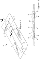
- Figure 1 is an isometric view of a typical transmissive pulse oximetry sensor of the type in which the LED's and the light detector are mounted on a common flexible web.
- Figure 2 is a cross-sectional view taken along the line 2 -- 2 of Figure 1.
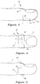
- Figure 3 is a cross-sectional view showing the pulse oximetry sensor of Figure 1 applied with a lateral misalignment.
- Figure 4 is a cross-sectional view showing the pulse oximetry sensor of Figure 1 applied with a longitudinal misalignment.
- Figure 5 is a cross-sectional view showing the pulse oximetry sensor of Figure 1 applied with an angular misalignment.
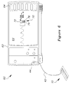
- Figure 6 is a cross-sectional view of a pulse oximetry system in which a pulse oximetry monitor using one embodiment of the inventive aiming guide system is connected to the pulse oximetry sensor of Figure 1.
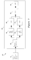
- Figure 7 is a block diagram of the pulse oximetry monitor of Figure 6.
- Figure 8 is a flow chart of the software used to program a microprocessor used in the pulse oximetry monitor of Figures 6 and 7.
- a conventional transmissive pulse oximetry sensor 10 of the type that can be used with the inventive alignment system is illustrated in Figures 1 and 2.
- the sensor 10 includes an elongated web 12 of flexible material, such as a woven fabric.
- One surface 14 of the web 12 is coated with a conventional adhesive 16 so that the web will stick to the skin of a patient and to the opposite surface 18 of the web 12 if the web 12 is wrapped around itself.
- a retention sheet 30 is secured to the adhesive surface 14 at one end of the web 12.
- a pair of light emitting diodes (“LED's") 32 mounted on a common substrate are sandwiched between the retention sheet 30 and the web 12 beneath a first transparent window 34 formed in the retention sheet 30.
- a conventional light detector 36 is sandwiched between the retention sheet 30 and the web 12 beneath a second transparent window 38 formed in the retention sheet 30.
- the LED's 32 and light detector 36 are longitudinally spaced apart from each other by a distance that allows the LED's 32 and light detector 36 to directly face each other when the web 12 is doubled over and attached to the skin of the patient on opposite surfaces of a body part, such as a finger.
- the LED's 32 and the light detector 36 are connected to respective wires, indicated generally at 40, which are bundled together to form a cable 42 that terminates in an electrical connector 44.
- the connector 44 plugs into a conventional pulse oximetry monitor (not shown in Figure 1) to determine and display the oxygen saturation of vascularized tissues positioned between the LED's 32 and the light detector 36.
- the sensor 10 is normally shipped and stored with the adhesive surface 14 of the web 12 attached to a release sheet 46 of plastic or the like having properties that allow the adhesive to easily separate from the sheet 46.
- the release sheet 46 is stripped from the web 12, and the web 12 is attached to a body part, such as a finger, toe, hand, etc. of a patient, by forcing the adhesive surface 14 against the skin of the patient.
- the web 12 should be attached so that the LED's 32 are positioned opposite and directly face the light sensor 36.
- alignment marks 50, 52, 54 are placed on the exposed surface 18 opposite the adhesive surface 14 as illustrated in Figure 1.
- the first alignment mark 50 consists of a solid transverse line passing directly over the center of the LED's 32 with a circle at the center of the web 12 overlying the LED's 32.
- the third alignment mark 54 consists of a solid transverse line passing directly over the center of the light detector 36 with a circle at the center of the web 12 overlying the light detector 36.
- the second alignment mark 52 consists of a dotted transverse line positioned midway between the first alignment mark 50 and the third alignment mark 54.
- the alignment marks 50 -- 54 attempt to assist the medical practitioner in applying the sensor 10 because the circles in the alignment marks 50, 54 should be directly opposite each other when the sensor 10 is properly attached.
- the alignment marks 50, 54 are placed on opposite surfaces of a finger, toe, or hand, for example, the dotted alignment mark 52 should extend along the side of the finger, toe, or hand.
- these alignment marks 50 -- 54 are often not effective in assisting medical practitioners in properly attaching the sensor 10 for the reasons explained below with reference to Figures 3 -- 5.
- FIG. 3 One type of potential misalignment of the pulse oximetry sensor 10 of Figures 1 and 2 is illustrated in Figure 3.
- the web 12 is wrapped around the finger F of a patient.
- the web 12 is wrapped in a slight spiral configuration.
- the LED's 32 on the top of the finger F do not directly overly the light detector 36 on the bottom of the finger F.
- the LED's 32 and light detector 36 are displaced from each other by a distance L1 along an axis extending laterally with respect to the web 12. Under these circumstances, the amount of light transmitted from the LED's 32 to the light detector 36 may be insufficient to provide highly accurate measurements of oxygen saturation.
- the alignment marks 50 -- 54 on the web 12 are incapable of preventing lateral misalignments of the type shown in Figure 3 because the marks 50 -- 54 are covered by the portion of the web 12 extending beyond the retention sheet 30. In fact, the portion of the web 12 containing the LED's 32 and the light detector 36 is covered by the extended portion of the web 12, thus making it virtually impossible to visually detect lateral misalignments.
- FIG 4 Another type of potential misalignment of the pulse oximetry sensor 10 of Figures 1 and 2 is illustrated in Figure 4.
- the web 12 is wrapped around the finger F of a patient.
- the LED's 32 are mounted on the web 12 at a distance from the light detector 36 that is different from one-half the circumference of the finger F.
- the LED's 32 on the top of the finger F do not directly overly the light detector 36 on the bottom of the finger F.
- the LED's 32 and light detector 36 are displaced from each other by a distance L2 along an axis extending along the length of the web 12. Under these circumstances, the amount of light transmitted from the LED's 32 to the light detector 36 may also be insufficient to provide highly accurate measurements of oxygen saturation.
- the alignment marks 50 -- 54 on the web 12 are also incapable of preventing longitudinal misalignments of the type shown in Figure 4 because it generally will not be possible to view both alignment marks 50 and 54 at the same time since they are on opposite surfaces of the finger F. Moreover in many application, including the application shown in Figure 3, the alignment marks 50 -- 54 will be covered by the portion of the web 12 extending beyond the retention sheet 30.
- FIG. 5 Still another type of potential misalignment of the pulse oximetry sensor 10 of Figure 1 is illustrated in Figure 5.
- the web 12 is wrapped around a portion of the finger F of a patient in which the opposite surface of the finger F are not parallel to each other.
- the LED's 32 on the top of the finger F do not directly face the light detector 36 on the bottom of the finger F. Instead, the illumination axes of the LED's 32 and the axis of sensitivity of the light detector 36 are displaced from each other by an angle J.
- This angular misalignment may prevent the amount of light transmitted from the LED's 32 to the light detector 36 from being sufficient to provide highly accurate measurements of oxygen saturation, particularly where the illumination axes of the LED's 32 and the axis of sensitivity of the light detector 36 are relatively narrow.
- the alignment marks 50 -- 54 on the web 12 are also incapable of preventing angular misalignments of the type shown in Figure 5 because it generally will not be possible to view both alignment marks 50 and 54 at the same time even if the marks 50 -- 54 were not covered by the extended portion of the web 12. Also, it would be difficult to verify visually that the circle portions of the alignment marks 50, 54 are sufficiently parallel to each other.
- the pulse oximetry system 60 includes the transmissive pulse oximetry sensor 10 illustrated in Figures 1 and 2 connected to a pulse oximetry monitor 62 having a cathode ray tube screen 64.
- the monitor 62 illustrated in Figure 6 is of the type using "softkeys” and a "touch screen” to control its operation.
- the "keys” are generated on the face of the screen by conventional software in the monitor 62, and the selection of a "key” is detected by a set of LED's (not shown) and light detectors (not shown) mounted on opposite sides of a bezel 66 surrounding the screen 64.
- the monitor 62 employing the inventive alignment system departs from the prior art by adding to the screen 64 an alignment guide display. More specifically, a portion of the screen 64 contains a rectangular bar graph 70 defined by a rectangular outline 72 of fixed dimensions. The outline 72 is partially filled with an illuminated area 74. The height of the illuminated area 74 is a function of the magnitude of the light transmitted from the LED's 32 to the light detector 36. As a result, when the pulse oximetry sensor 10 is being attached to a patient, the height of the illuminated are 74 will provide the medical practitioner attaching the sensor 10 with feedback about amount of light being transmitted from the LED's 32 to the light detector 36.
- the position of the web 12 can then be adjusted to maximize the height of the illuminated area 74, thus optimizing the accuracy of the pulse oximetry system 60. It will be apparent to one skilled in the art that other types of graphical displays as well as numeric readouts could also be used without departing from the invention.
- the bar graph 70 may simply display the degree of optical coupling between the LED's 32 and the light detector 36, or it may include an alarm for indicating that the optical coupling between the LED's 32 and the light detector 36 is insufficient to ensure accurate measurements.
- One type of alarm illustrated in Figure 6 uses a solid line 76 extending across the bar graph outline 72 at a height corresponding to a predetermined optical coupling between the LED's 32 and the light detector 36.
- the predetermined optical coupling represented by the line 76 preferably corresponds to the point where the optical coupling falls to a level that is insufficient to obtain oxygen saturation measurements having more than a predetermined degree of accuracy.
- the line 76 may be set at any level depending upon the degree of misalignment that is to be permitted.
- the entire bar graph 70 flashes off and on to alert the practitioner that the position of the pulse oximetry sensor 10 should be adjusted.
- Other types of alarms including flashing lights, audible alarms, etc., could also be used.
- FIG. 7 A block diagram of the pulse oximetry system 60 using the monitor 62 of Figure 6 is illustrated in Figure 7. It should be recognized that the portion of the monitor 62 that drives the LED's 32, processes the signal output by the light detector 36, calculates oxygen saturation, and displays the result is conventional. Thus, in the interest of brevity, these aspects of the monitor 62 are not described in detail herein.
- the monitor 62 includes a sensor interface circuit 80 of conventional design that alternately pulses the LED's 32 ( Figures 1 and 2) in the sensor 10 to cause the LED's 32 to alternately emit red and infra-red light.
- the light passes through vascularized tissues to the light detector 36 thereby causing the light detector 36 to output an indicator signal that is a function of the magnitude of the light transmitted through the tissues.
- the indicator signal is then amplified by the interface circuit 80 and directed to one of two outputs 82, 84 depending upon which LED 32 is illuminated when the indicator signal is received.
- the indicator signal corresponding to the transmission of light from the red LED to the light detector 36 is applied from the output 82 to a first sample and hold ("S/H") circuit 86 of conventional design which periodically outputs analog samples. Each of these analog samples is a voltage corresponding to the amplitude of the red indicator signal from the interface circuit 80 when the sample was taken.
- the analog samples generated by the S/H circuit 86 are then converted to a digital value corresponding to the voltage of each sample by a conventional analog-to-digital (“A/D”) converter 88.
- A/D analog-to-digital
- the resulting digital value indicative of the transmission of red light from the LED 32 to the light detector 36 is applied to an input port of a conventional microprocessor 90.
- the indicator signal corresponding to the transmission of light from the infra-red LED to the light detector 36 is processed by similar circuitry. Specifically, the infra-red indicator signal is applied from the output 84 of the sensor interface circuit 80 to a second S/H circuit 92. Each of the analog samples generated by the S/H circuit 92 is then converted to a corresponding digital value by a second A/D converter 94. The resulting digital value indicative of the transmission of infra-red light from the LED 32 to the light detector 36 is applied to a second input port of the microprocessor 90.
- the microprocessor 90 calculates the oxygen saturation of the patient from the red and infra-red digital samples in a conventional manner using the familiar Lambert-Beers equation. The result of the calculation is then displayed on the face of the cathode ray tube screen 64 ( Figure 6) in a known manner.
- the microprocessor 90 operates according to a program of instructions that are stored in memory that is internal to the microprocessor 90.
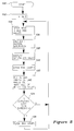
- a flow chart showing this program from which one skilled in the art can easily and quickly write source code for a selected microprocessor type is illustrated in Figure 8. It should be noted that the flow chart of Figure 8 does not show the software in substantial detail for performing pulse oximetry functions, such as illuminating the LED's, calculating oxygen saturation, driving the CRT screen 64, etc.
- pulse oximetry functions such as illuminating the LED's, calculating oxygen saturation, driving the CRT screen 64, etc.
- Such software is well known to one skilled in the art of pulse oximetry design since such software is used in a number of commercially available pulse oximetry monitors.
- the program illustrated in Figure 8 is entered at power on through step 100, and conventional initialization of flags, registers, etc. occurs at 102.
- the program then causes the microprocessor 90 ( Figure 7) to read the digitized red and infra-red samples from the A/D converters 88, 94 at step 104.
- the microprocessor 90 calculates oxygen saturation from these red and infra-red samples in a conventional manner at 106, and displays the calculated value on the CRT screen 64 at 108.
- the microprocessor 90 may also display the calculated value on the CRT screen 64 in graphical as well as numerical formats. For example, the microprocessor 90 may draw a running graph on the CRT screen 64 showing oxygen saturation as a function of time.
- Step 120 of the program causes the microprocessor 90 to draw the rectangular outline 70 (Figure 6) of the bar graph 70 as well as the solid line 76 designating the alarm limit threshold described above with reference to Figure 6.
- step 122 the microprocessor 90 fills in the outline 72 to form the illuminated area 74 depending upon the magnitude of either the digitized red sample generated by the A/D converter 88 or the digitized infra-red sample generated by the A/D converter 94. Although not necessary, a combination of both the red sample and the infra-red sample could also be used.
- the value corresponding to the height of the illuminated area 74 is compared to the alarm limit threshold represented by the solid line 76 at step 124. If the program determines at step 124 that the sample used to set the height of the illuminated area 74 is less than the alarm limit threshold, the program causes the microprocessor 90 to flash the bar graph 70 at step 126. The program then returns to step 104 to obtain new red and infra-red samples.
- step 124 If the program determines at step 124 that the sample used to set the height of the illuminated area 74 is not less than the alarm limit threshold, the program returns directly to step 104 without passing through step 126 to flash the bar graph 70. The program continues to execute steps 104 -- 126, thereby continuously displaying in essentially real time both the level of oxygen saturation as well as a guide for properly attaching the pulse oximetry sensor 10.
- the inventive alignment guide system thus easily and quickly allows medical practitioners to properly attach transmissive pulse oximeter sensors as well as allowing them to monitor the correctness of the attachment during use. Furthermore, the alignment guide system may be used with virtually any type of conventional pulse oximetry monitor connected to such transmissive pulse oximeter sensors.
Abstract
An alignment guide system for use with conventional pulse oximetry monitors (60) connected to transmissive pulse oximetry sensors (10). The system generates a bar graph (70) or other display showing the magnitude of the optical coupling between the LED's (32) and light detector (36) used in the sensor (10). By manipulating the position of the sensor (10) while observing the bar graph (70), medical practitioners can optimize the amount of light from the LED's (32) reaching the light detector (36). The bar graph (70) also contains an alarm limit marker (76). If the bar graph area (74) falls below the alarm limit marker (76), the entire bar graph (70) flashes to alert the medical practitioner that the amount of light transmitted to the LED's (32) to the light detector (36) may not be enough to permit sufficiently accurate oxygen saturation measurements.
Description
- This invention relates to pulse oximeters, and more particularly, to pulse oximeters used with light transmissive pulse oximetry sensors.
- Pulse oximeters are in common use in hospitals and other medical facilities to measure the degree of oxygen saturation of a patient's blood. Conventional pulse oximeters typically operate according to the Lambert-Beers law which is based upon the blood's property of differentially absorbing infra-red and red light depending upon the degree of oxygen saturation of the patient's blood.
- Conventional pulse oximeters typically consist of a pulse oximetry sensor connected to a pulse oximetry monitor. The monitor typically includes circuitry for interfacing with the sensor as well as a display for providing a readout of the percent of oxygen saturation. The sensor typically contains a first light emitting diode ("LED") emitting red light, a second LED emitting infra-red light, and a light detector for sensing the red and infra-red light after passing through vascularized tissues of the patient. The first and second LED's are normally time multiplexed by alternately applying illumination signals to the LED's so that a single light detector can be used.
- There are two types of pulse oximetry sensors in present use, namely "reflectance sensors" and "transmissive sensors." In a reflectance sensor, the LED's and light detector are mounted adjacent each other on a single carrier. The carrier is placed against the skin of a patient so that light from the LED's passes into the tissues of the patient, and some of this light is internally reflected back to the light detector. The magnitude of the reflected light is an inverse function of the amount of light absorbed in the tissues. The differential reflection of red and infra-red light thus provides an indication of the degree of oxygen saturation in the tissues.
- In transmissive pulse oximetry sensors, the LED's are mounted adjacent to each other in a first carrier, and the light detector is mounted in either a second carrier or in a separate portion of the first carrier. As a result, the LED's and the light detector can be placed on opposite surfaces of vascularized tissues, such as a finger or an ear lobe, with the LED's and the light detector facing each other. Light from the LED's is transmitted through the tissues to the light detector. The magnitude of the light transmitted to the light detector is an inverse function of the amount of light absorbed in the tissues. The differential transmission of red and infra-red light thus provides an indication of the degree of oxygen saturation in the tissues.
- The geometry between the LED's and the light detector can be critical to the optimum performance of pulse oximeters. Ideally, the optical paths between the LED's and the light detector are as short as possible to maximize the usable light reaching the light detector. However, if the LED's and/or the light detector are either not in the proper position or not facing the proper direction, the accuracy of the oxygen saturation measurement can be degraded.
- The geometry between the LED's and the light detector in a reflectance sensor is fixed because the LED's and light detector are mounted on the same carrier. Thus, variations in the geometry between the LED's and the light detector is not a problem for reflectance sensors. Similarly, the geometry between the LED's and the light detector in many transmissive sensors is also fixed because the first and second carriers are pivotally connected to each other. Variations in the geometry between the LED's and the light detector is also not a problem for these types of transmissive sensors.
- One commonly used transmissive pulse oximetry sensor uses as the carrier an elongated flexible web having one of its surfaces coated with an adhesive in a manner similar to a bandage strip. The LED's are mounted in or on the web adjacent to each other, and the light detector is mounted in or on the web at a location that is longitudinally spaced from the LED's. The sensor is generally used by wrapping the web around a finger or a portion of a hand or foot so that the LED's are directly opposite the light detector.
- In practice, pulse oximetry sensors having LED's and a light detector mounted on a common flexible web are often applied improperly so that the LED's are either not directly opposite the light detector or not directly facing the light detector. Three types of alignment errors can occur either alone or in combination. In the first, the web is attached to the patient so that the LED's are laterally offset from the light detector. For example, the LED's will be laterally offset from the light detector if the web is wrapped around a finger in a spiral. In the second type of alignment error, the web is attached to the patient so that the LED's are longitudinally offset from the light detector. An example of this condition is where the web is wrapped around a finger, but one-half the circumference of the finger is not substantially the same distance as the spacing between the LED's and the light detector. Finally, the third type of alignment error occurs if the LED's do not directly face the light detector even though they may be positioned directly opposite the light detector. This type of alignment error may occur if the opposite surfaces of the skin to which the LED's and light detector are attached are not parallel to each other.
- As mentioned above, these three types of alignment errors can occur either alone or in combination. The possibility of three different types of alignment errors occurring, coupled with inevitable variations in the size and shape of attachment locations among patients and variations in the training and skill of medical personnel attaching sensors, often hurriedly in emergency conditions, makes it very difficult to be sure that sensors are attached properly to provide accurate oxygen saturation measurements.
- Although manufacturers of pulse oximetry sensors having LED's and a light detector mounted on a common web have recognized the importance of properly aligning the LED's with the light detector, they have been unable to devise any suitable technique to quickly and accurately ensure optimum alignment between the LED's and the light detector. One approach has been to place alignment marks on the exposed surface of the web over the LED's and the light detector. These alignment marks are in the form of respective lines extending laterally across the web over the LED's and light detector. In theory, the medical practitioner can make sure that the alignment marks are opposite each other to ensure that the LED's are properly aligned with the light detector. However, this approach has often proven to be inadequate for several reasons. First, the alignment marks are often covered up by portions of the web extending beyond the LED's and light detector which are wrapped around the portion of the web containing the alignment marks. Second, it is sometimes difficult to determine if the marks are, in fact, directly opposite each other even when the marks are clearly visible. Third, even if the marks are, in fact, longitudinally and laterally aligned with each other, the LED's may still not be directly facing the light detector. Finally, while the above-described approach may assist in providing proper alignment, it does not allow one to verify that the alignment is, in fact, optimum or even acceptable after the sensor has been installed.
- The inventive system for aligning a light source with a light detector in a pulse oximetry sensor may be either an integral part of a pulse oximetry monitor or a system used with a separate pulse oximetry monitor. The alignment system includes a light driver connected to the light source to energize the light source, and a receiver circuit connected to the light detector to generate an indicator signal corresponding to the magnitude of the light transmitted from the light source to the light detector. The receiver circuit is connected to a display which provides a visual indication of the magnitude of the indicator signal. As a result, the display can be monitored while the pulse oximetry sensor is being attached to a patient to optimize the alignment between the light source and the light detector.
- The display preferably includes a bar graph on which the magnitude of the indicator signal is displayed. A threshold marking may be placed on the bar graph at a position corresponding to the magnitude of the indicator signal at which the light transmitted from the light source to the light detector falls to an unacceptable level. The threshold marking can then be used to set an alarm limit by comparing the indicator signal to a predetermined reference value, and generating an alarm signal when the magnitude of the indicator signal has fallen below the reference value. The alarm signal can then trigger an audible or visible alarm such as, for example, by flashing at least a portion of the bar graph when the light transmitted from the light source to the light detector falls below the acceptable level.
- Figure 1 is an isometric view of a typical transmissive pulse oximetry sensor of the type in which the LED's and the light detector are mounted on a common flexible web.
- Figure 2 is a cross-sectional view taken along the
line 2 -- 2 of Figure 1. - Figure 3 is a cross-sectional view showing the pulse oximetry sensor of Figure 1 applied with a lateral misalignment.
- Figure 4 is a cross-sectional view showing the pulse oximetry sensor of Figure 1 applied with a longitudinal misalignment.
- Figure 5 is a cross-sectional view showing the pulse oximetry sensor of Figure 1 applied with an angular misalignment.
- Figure 6 is a cross-sectional view of a pulse oximetry system in which a pulse oximetry monitor using one embodiment of the inventive aiming guide system is connected to the pulse oximetry sensor of Figure 1.
- Figure 7 is a block diagram of the pulse oximetry monitor of Figure 6.
- Figure 8 is a flow chart of the software used to program a microprocessor used in the pulse oximetry monitor of Figures 6 and 7.
- A conventional transmissive
pulse oximetry sensor 10 of the type that can be used with the inventive alignment system is illustrated in Figures 1 and 2. Thesensor 10 includes anelongated web 12 of flexible material, such as a woven fabric. Onesurface 14 of theweb 12 is coated with aconventional adhesive 16 so that the web will stick to the skin of a patient and to theopposite surface 18 of theweb 12 if theweb 12 is wrapped around itself. - As illustrated in Figure 2, a
retention sheet 30 is secured to theadhesive surface 14 at one end of theweb 12. A pair of light emitting diodes ("LED's") 32 mounted on a common substrate are sandwiched between theretention sheet 30 and theweb 12 beneath a firsttransparent window 34 formed in theretention sheet 30. Similarly, a conventionallight detector 36 is sandwiched between theretention sheet 30 and theweb 12 beneath a secondtransparent window 38 formed in theretention sheet 30. The LED's 32 andlight detector 36 are longitudinally spaced apart from each other by a distance that allows the LED's 32 andlight detector 36 to directly face each other when theweb 12 is doubled over and attached to the skin of the patient on opposite surfaces of a body part, such as a finger. - The LED's 32 and the
light detector 36 are connected to respective wires, indicated generally at 40, which are bundled together to form acable 42 that terminates in anelectrical connector 44. Theconnector 44 plugs into a conventional pulse oximetry monitor (not shown in Figure 1) to determine and display the oxygen saturation of vascularized tissues positioned between the LED's 32 and thelight detector 36. - The
sensor 10 is normally shipped and stored with theadhesive surface 14 of theweb 12 attached to arelease sheet 46 of plastic or the like having properties that allow the adhesive to easily separate from thesheet 46. When thesensor 10 is to be used, therelease sheet 46 is stripped from theweb 12, and theweb 12 is attached to a body part, such as a finger, toe, hand, etc. of a patient, by forcing theadhesive surface 14 against the skin of the patient. As mentioned above, theweb 12 should be attached so that the LED's 32 are positioned opposite and directly face thelight sensor 36. - In an attempt to facilitate proper alignment between the LED's 32 and the
light detector 36, alignment marks 50, 52, 54 are placed on the exposedsurface 18 opposite theadhesive surface 14 as illustrated in Figure 1. Thefirst alignment mark 50 consists of a solid transverse line passing directly over the center of the LED's 32 with a circle at the center of theweb 12 overlying the LED's 32. Similarly, thethird alignment mark 54 consists of a solid transverse line passing directly over the center of thelight detector 36 with a circle at the center of theweb 12 overlying thelight detector 36. Finally, thesecond alignment mark 52 consists of a dotted transverse line positioned midway between thefirst alignment mark 50 and thethird alignment mark 54. - The alignment marks 50 -- 54 attempt to assist the medical practitioner in applying the
sensor 10 because the circles in the alignment marks 50, 54 should be directly opposite each other when thesensor 10 is properly attached. When the alignment marks 50, 54 are placed on opposite surfaces of a finger, toe, or hand, for example, the dottedalignment mark 52 should extend along the side of the finger, toe, or hand. However, in practice, these alignment marks 50 -- 54 are often not effective in assisting medical practitioners in properly attaching thesensor 10 for the reasons explained below with reference to Figures 3 -- 5. - One type of potential misalignment of the
pulse oximetry sensor 10 of Figures 1 and 2 is illustrated in Figure 3. As illustrated in Figure 3, theweb 12 is wrapped around the finger F of a patient. However, theweb 12 is wrapped in a slight spiral configuration. As a result, the LED's 32 on the top of the finger F do not directly overly thelight detector 36 on the bottom of the finger F. Instead, the LED's 32 andlight detector 36 are displaced from each other by a distance L₁ along an axis extending laterally with respect to theweb 12. Under these circumstances, the amount of light transmitted from the LED's 32 to thelight detector 36 may be insufficient to provide highly accurate measurements of oxygen saturation. - It should be noted that the alignment marks 50 -- 54 on the
web 12 are incapable of preventing lateral misalignments of the type shown in Figure 3 because themarks 50 -- 54 are covered by the portion of theweb 12 extending beyond theretention sheet 30. In fact, the portion of theweb 12 containing the LED's 32 and thelight detector 36 is covered by the extended portion of theweb 12, thus making it virtually impossible to visually detect lateral misalignments. - Another type of potential misalignment of the
pulse oximetry sensor 10 of Figures 1 and 2 is illustrated in Figure 4. As illustrated in Figure 4, theweb 12 is wrapped around the finger F of a patient. However, the LED's 32 are mounted on theweb 12 at a distance from thelight detector 36 that is different from one-half the circumference of the finger F. As a result, the LED's 32 on the top of the finger F do not directly overly thelight detector 36 on the bottom of the finger F. Instead, the LED's 32 andlight detector 36 are displaced from each other by a distance L₂ along an axis extending along the length of theweb 12. Under these circumstances, the amount of light transmitted from the LED's 32 to thelight detector 36 may also be insufficient to provide highly accurate measurements of oxygen saturation. - As with lateral misalignment of the type illustrated in Figure 3, the alignment marks 50 -- 54 on the
web 12 are also incapable of preventing longitudinal misalignments of the type shown in Figure 4 because it generally will not be possible to view both alignment marks 50 and 54 at the same time since they are on opposite surfaces of the finger F. Moreover in many application, including the application shown in Figure 3, the alignment marks 50 -- 54 will be covered by the portion of theweb 12 extending beyond theretention sheet 30. - Still another type of potential misalignment of the
pulse oximetry sensor 10 of Figure 1 is illustrated in Figure 5. As illustrated in Figure 5, theweb 12 is wrapped around a portion of the finger F of a patient in which the opposite surface of the finger F are not parallel to each other. As a result, the LED's 32 on the top of the finger F do not directly face thelight detector 36 on the bottom of the finger F. Instead, the illumination axes of the LED's 32 and the axis of sensitivity of thelight detector 36 are displaced from each other by an angle J. This angular misalignment may prevent the amount of light transmitted from the LED's 32 to thelight detector 36 from being sufficient to provide highly accurate measurements of oxygen saturation, particularly where the illumination axes of the LED's 32 and the axis of sensitivity of thelight detector 36 are relatively narrow. - The alignment marks 50 -- 54 on the
web 12 are also incapable of preventing angular misalignments of the type shown in Figure 5 because it generally will not be possible to view both alignment marks 50 and 54 at the same time even if themarks 50 -- 54 were not covered by the extended portion of theweb 12. Also, it would be difficult to verify visually that the circle portions of the alignment marks 50, 54 are sufficiently parallel to each other. - One embodiment of a
pulse oximetry system 60 employing the inventive alignment system is illustrated in Figure 6. Thepulse oximetry system 60 includes the transmissivepulse oximetry sensor 10 illustrated in Figures 1 and 2 connected to a pulse oximetry monitor 62 having a cathoderay tube screen 64. Themonitor 62 illustrated in Figure 6 is of the type using "softkeys" and a "touch screen" to control its operation. In monitors of this type, the "keys" are generated on the face of the screen by conventional software in themonitor 62, and the selection of a "key" is detected by a set of LED's (not shown) and light detectors (not shown) mounted on opposite sides of a bezel 66 surrounding thescreen 64. - The
monitor 62 employing the inventive alignment system departs from the prior art by adding to thescreen 64 an alignment guide display. More specifically, a portion of thescreen 64 contains arectangular bar graph 70 defined by arectangular outline 72 of fixed dimensions. Theoutline 72 is partially filled with an illuminatedarea 74. The height of the illuminatedarea 74 is a function of the magnitude of the light transmitted from the LED's 32 to thelight detector 36. As a result, when thepulse oximetry sensor 10 is being attached to a patient, the height of the illuminated are 74 will provide the medical practitioner attaching thesensor 10 with feedback about amount of light being transmitted from the LED's 32 to thelight detector 36. The position of theweb 12 can then be adjusted to maximize the height of the illuminatedarea 74, thus optimizing the accuracy of thepulse oximetry system 60. It will be apparent to one skilled in the art that other types of graphical displays as well as numeric readouts could also be used without departing from the invention. - The
bar graph 70 may simply display the degree of optical coupling between the LED's 32 and thelight detector 36, or it may include an alarm for indicating that the optical coupling between the LED's 32 and thelight detector 36 is insufficient to ensure accurate measurements. One type of alarm illustrated in Figure 6 uses asolid line 76 extending across thebar graph outline 72 at a height corresponding to a predetermined optical coupling between the LED's 32 and thelight detector 36. The predetermined optical coupling represented by theline 76 preferably corresponds to the point where the optical coupling falls to a level that is insufficient to obtain oxygen saturation measurements having more than a predetermined degree of accuracy. However, theline 76 may be set at any level depending upon the degree of misalignment that is to be permitted. When the illuminatedarea 74 drops below the level of theline 76, theentire bar graph 70 flashes off and on to alert the practitioner that the position of thepulse oximetry sensor 10 should be adjusted. Other types of alarms, including flashing lights, audible alarms, etc., could also be used. - A block diagram of the
pulse oximetry system 60 using themonitor 62 of Figure 6 is illustrated in Figure 7. It should be recognized that the portion of themonitor 62 that drives the LED's 32, processes the signal output by thelight detector 36, calculates oxygen saturation, and displays the result is conventional. Thus, in the interest of brevity, these aspects of themonitor 62 are not described in detail herein. - The
monitor 62 includes asensor interface circuit 80 of conventional design that alternately pulses the LED's 32 (Figures 1 and 2) in thesensor 10 to cause the LED's 32 to alternately emit red and infra-red light. The light passes through vascularized tissues to thelight detector 36 thereby causing thelight detector 36 to output an indicator signal that is a function of the magnitude of the light transmitted through the tissues. The indicator signal is then amplified by theinterface circuit 80 and directed to one of two outputs 82, 84 depending upon which LED 32 is illuminated when the indicator signal is received. - The indicator signal corresponding to the transmission of light from the red LED to the
light detector 36 is applied from the output 82 to a first sample and hold ("S/H")circuit 86 of conventional design which periodically outputs analog samples. Each of these analog samples is a voltage corresponding to the amplitude of the red indicator signal from theinterface circuit 80 when the sample was taken. The analog samples generated by the S/H circuit 86 are then converted to a digital value corresponding to the voltage of each sample by a conventional analog-to-digital ("A/D")converter 88. The resulting digital value indicative of the transmission of red light from theLED 32 to thelight detector 36 is applied to an input port of aconventional microprocessor 90. - The indicator signal corresponding to the transmission of light from the infra-red LED to the
light detector 36 is processed by similar circuitry. Specifically, the infra-red indicator signal is applied from the output 84 of thesensor interface circuit 80 to a second S/H circuit 92. Each of the analog samples generated by the S/H circuit 92 is then converted to a corresponding digital value by a second A/D converter 94. The resulting digital value indicative of the transmission of infra-red light from theLED 32 to thelight detector 36 is applied to a second input port of themicroprocessor 90. - The
microprocessor 90 calculates the oxygen saturation of the patient from the red and infra-red digital samples in a conventional manner using the familiar Lambert-Beers equation. The result of the calculation is then displayed on the face of the cathode ray tube screen 64 (Figure 6) in a known manner. - The
microprocessor 90 operates according to a program of instructions that are stored in memory that is internal to themicroprocessor 90. A flow chart showing this program from which one skilled in the art can easily and quickly write source code for a selected microprocessor type is illustrated in Figure 8. It should be noted that the flow chart of Figure 8 does not show the software in substantial detail for performing pulse oximetry functions, such as illuminating the LED's, calculating oxygen saturation, driving theCRT screen 64, etc. Such software is well known to one skilled in the art of pulse oximetry design since such software is used in a number of commercially available pulse oximetry monitors. - The program illustrated in Figure 8 is entered at power on through
step 100, and conventional initialization of flags, registers, etc. occurs at 102. The program then causes the microprocessor 90 (Figure 7) to read the digitized red and infra-red samples from the A/D converters step 104. Themicroprocessor 90 calculates oxygen saturation from these red and infra-red samples in a conventional manner at 106, and displays the calculated value on theCRT screen 64 at 108. Themicroprocessor 90 may also display the calculated value on theCRT screen 64 in graphical as well as numerical formats. For example, themicroprocessor 90 may draw a running graph on theCRT screen 64 showing oxygen saturation as a function of time. - After the oxygen saturation value has been displayed the program executes a number of steps that implement the inventive alignment guide function. Step 120 of the program causes the
microprocessor 90 to draw the rectangular outline 70 (Figure 6) of thebar graph 70 as well as thesolid line 76 designating the alarm limit threshold described above with reference to Figure 6. - The program then progresses to step 122 where the
microprocessor 90 fills in theoutline 72 to form the illuminatedarea 74 depending upon the magnitude of either the digitized red sample generated by the A/D converter 88 or the digitized infra-red sample generated by the A/D converter 94. Although not necessary, a combination of both the red sample and the infra-red sample could also be used. - Regardless of whether the red sample, the infra-red sample, or some combination of both samples is used to set the height of the illuminated
area 74, the value corresponding to the height of the illuminatedarea 74 is compared to the alarm limit threshold represented by thesolid line 76 atstep 124. If the program determines atstep 124 that the sample used to set the height of the illuminatedarea 74 is less than the alarm limit threshold, the program causes themicroprocessor 90 to flash thebar graph 70 atstep 126. The program then returns to step 104 to obtain new red and infra-red samples. If the program determines atstep 124 that the sample used to set the height of the illuminatedarea 74 is not less than the alarm limit threshold, the program returns directly to step 104 without passing throughstep 126 to flash thebar graph 70. The program continues to executesteps 104 -- 126, thereby continuously displaying in essentially real time both the level of oxygen saturation as well as a guide for properly attaching thepulse oximetry sensor 10. - The inventive alignment guide system thus easily and quickly allows medical practitioners to properly attach transmissive pulse oximeter sensors as well as allowing them to monitor the correctness of the attachment during use. Furthermore, the alignment guide system may be used with virtually any type of conventional pulse oximetry monitor connected to such transmissive pulse oximeter sensors.
Claims (6)
- A system for optimally positioning a light source with respect to a light detector in a plethysmograph sensor, said system comprising:
a light driver connected to said light source to energize said light source, thereby causing said light source to emit light;
a receiver circuit connected to said light detector, said receiver circuit generating an indicator signal that is indicative of the magnitude of the light transmitted from said light source to said light detector; and
a display operably connected to said receiver circuit to provide a visual display of said indicator signal so that said display can be monitored while said plethysmograph sensor is being attached to a patient in order to optimize the positioning of said light source with respect to said light detector. - The system of claim 1 wherein said display includes a bar graph on which the magnitude of said indicator signal is displayed as a function of a dimension of said bar graph.
- The system of claim 2 wherein said bar graph contains a threshold marking at a position on said bar graph corresponding to the magnitude of said indicator signal at which the light transmitted from said light source to said light detector falls below an acceptable level.
- The system of claim 3 further including alarm means for signaling when the magnitude of said indicator signal shown on said bar graph has fallen below said threshold marking.
- The system of claim 4 wherein said alarm means comprise:
comparitor means for comparing said indicator signal to a predetermined reference value, said comparitor means providing an alarm signal when the magnitude of said indicator signal has fallen below said reference value; and
alarm display means operatively coupled to said comparitor means and said display, said alarm display means flashing at least a portion of said bar graph responsive to said alarm signal thereby providing a visual indication when the light transmitted from said light source to said light detector falls below said acceptable level. - A pulse oximetry system, comprising:
a transmissive pulse oximetry sensor, comprising:
a flexible web having a surface coated with an adhesive so that said web can stick to the skin of a patient;
first and second light sources mounted on said web with said light sources adapted to generate light at respective wavelengths in a direction normal to the adhesive coated surface of said web; and
a light detector mounted on said web with said light detector adapted to receive light in a direction normal to the adhesive coated surface of said web, said light detector being spaced apart from said light sources so that said light detector and said light sources can face each other when said web is wrapped around a portion of said patient's body; and
a pulse oximetry monitor, comprising:
a light driver connected to said light sources to energize said light sources, thereby causing said light sources to emit light;
a receiver circuit connected to said light detector, said receiver circuit generating first and second indicator signals that are indicative of the magnitude of the light transmitted to said light detector from said first and second light sources, respectively; and
a processor operatively connected to said receiver circuit, said processor receiving said first and second indicator signals, calculating the oxygen saturation of tissues beneath the skin of said patient to which said pulse oximetry sensor is attached, and generating a saturation signal corresponding the oxygen saturation of said tissues;
a display operably connected to said processor and to said receiver circuit to receive said saturation signal and at least one of said indicator signals, said display providing a visual indication of the oxygen saturation of said tissues and the magnitude of the indicator signal received by said display so that said display can be monitored while said pulse oximetry sensor is being attached to said patient in order to optimize the alignment between said light sources and said light detector.
Applications Claiming Priority (2)
| Application Number | Priority Date | Filing Date | Title |
|---|---|---|---|
| US07/937,248 US5680857A (en) | 1992-08-28 | 1992-08-28 | Alignment guide system for transmissive pulse oximetry sensors |
| US937248 | 1992-08-28 |
Publications (1)
| Publication Number | Publication Date |
|---|---|
| EP0587009A1 true EP0587009A1 (en) | 1994-03-16 |
Family
ID=25469681
Family Applications (1)
| Application Number | Title | Priority Date | Filing Date |
|---|---|---|---|
| EP93113852A Withdrawn EP0587009A1 (en) | 1992-08-28 | 1993-08-30 | Alignment guide system for transmissive pulse oximetry sensors |
Country Status (3)
| Country | Link |
|---|---|
| US (1) | US5680857A (en) |
| EP (1) | EP0587009A1 (en) |
| CA (1) | CA2104992A1 (en) |
Cited By (31)
| Publication number | Priority date | Publication date | Assignee | Title |
|---|---|---|---|---|
| EP0808605A2 (en) * | 1996-05-23 | 1997-11-26 | Samsung Electronics Co., Ltd. | An optimal diagnosis point detector for noninvasive diagnosis of blood constituents and a noninvasive diagnostic device |
| WO2006123098A3 (en) * | 2005-05-16 | 2007-01-11 | Hutchinson Technology | Patient interface for spectroscopy applications |
| US7460897B1 (en) | 2005-05-16 | 2008-12-02 | Hutchinson Technology Incorporated | Patient interface for spectroscopy applications |
| US7572230B2 (en) * | 2002-10-15 | 2009-08-11 | Koninklijke Philips Electronics N.V. | Method for the presentation of information concerning variations of the perfusion |
| US7647084B2 (en) | 2005-08-08 | 2010-01-12 | Nellcor Puritan Bennett Llc | Medical sensor and technique for using the same |
| US7650177B2 (en) | 2005-09-29 | 2010-01-19 | Nellcor Puritan Bennett Llc | Medical sensor for reducing motion artifacts and technique for using the same |
| US7657296B2 (en) | 2005-08-08 | 2010-02-02 | Nellcor Puritan Bennett Llc | Unitary medical sensor assembly and technique for using the same |
| US7657295B2 (en) | 2005-08-08 | 2010-02-02 | Nellcor Puritan Bennett Llc | Medical sensor and technique for using the same |
| US7676253B2 (en) | 2005-09-29 | 2010-03-09 | Nellcor Puritan Bennett Llc | Medical sensor and technique for using the same |
| US7684842B2 (en) | 2006-09-29 | 2010-03-23 | Nellcor Puritan Bennett Llc | System and method for preventing sensor misuse |
| US7796403B2 (en) | 2006-09-28 | 2010-09-14 | Nellcor Puritan Bennett Llc | Means for mechanical registration and mechanical-electrical coupling of a faraday shield to a photodetector and an electrical circuit |
| US7869849B2 (en) | 2006-09-26 | 2011-01-11 | Nellcor Puritan Bennett Llc | Opaque, electrically nonconductive region on a medical sensor |
| US7881762B2 (en) | 2005-09-30 | 2011-02-01 | Nellcor Puritan Bennett Llc | Clip-style medical sensor and technique for using the same |
| US7894869B2 (en) | 2007-03-09 | 2011-02-22 | Nellcor Puritan Bennett Llc | Multiple configuration medical sensor and technique for using the same |
| US7899510B2 (en) | 2005-09-29 | 2011-03-01 | Nellcor Puritan Bennett Llc | Medical sensor and technique for using the same |
| US8073518B2 (en) | 2006-05-02 | 2011-12-06 | Nellcor Puritan Bennett Llc | Clip-style medical sensor and technique for using the same |
| US8145288B2 (en) | 2006-08-22 | 2012-03-27 | Nellcor Puritan Bennett Llc | Medical sensor for reducing signal artifacts and technique for using the same |
| US8175671B2 (en) | 2006-09-22 | 2012-05-08 | Nellcor Puritan Bennett Llc | Medical sensor for reducing signal artifacts and technique for using the same |
| US8190225B2 (en) | 2006-09-22 | 2012-05-29 | Nellcor Puritan Bennett Llc | Medical sensor for reducing signal artifacts and technique for using the same |
| US8219170B2 (en) | 2006-09-20 | 2012-07-10 | Nellcor Puritan Bennett Llc | System and method for practicing spectrophotometry using light emitting nanostructure devices |
| US8260391B2 (en) | 2005-09-12 | 2012-09-04 | Nellcor Puritan Bennett Llc | Medical sensor for reducing motion artifacts and technique for using the same |
| US8265724B2 (en) | 2007-03-09 | 2012-09-11 | Nellcor Puritan Bennett Llc | Cancellation of light shunting |
| US8280469B2 (en) | 2007-03-09 | 2012-10-02 | Nellcor Puritan Bennett Llc | Method for detection of aberrant tissue spectra |
| US8315685B2 (en) | 2006-09-27 | 2012-11-20 | Nellcor Puritan Bennett Llc | Flexible medical sensor enclosure |
| US8346328B2 (en) | 2007-12-21 | 2013-01-01 | Covidien Lp | Medical sensor and technique for using the same |
| US8352009B2 (en) | 2005-09-30 | 2013-01-08 | Covidien Lp | Medical sensor and technique for using the same |
| US8352004B2 (en) | 2007-12-21 | 2013-01-08 | Covidien Lp | Medical sensor and technique for using the same |
| US8386002B2 (en) | 2005-09-30 | 2013-02-26 | Covidien Lp | Optically aligned pulse oximetry sensor and technique for using the same |
| US8396527B2 (en) | 2006-09-22 | 2013-03-12 | Covidien Lp | Medical sensor for reducing signal artifacts and technique for using the same |
| US8649839B2 (en) | 1996-10-10 | 2014-02-11 | Covidien Lp | Motion compatible sensor for non-invasive optical blood analysis |
| US9907494B2 (en) | 2012-04-18 | 2018-03-06 | Hutchinson Technology Incorporated | NIRS device with optical wavelength and path length correction |
Families Citing this family (106)
| Publication number | Priority date | Publication date | Assignee | Title |
|---|---|---|---|---|
| US9468378B2 (en) | 1997-01-27 | 2016-10-18 | Lawrence A. Lynn | Airway instability detection system and method |
| US9042952B2 (en) | 1997-01-27 | 2015-05-26 | Lawrence A. Lynn | System and method for automatic detection of a plurality of SPO2 time series pattern types |
| US8932227B2 (en) | 2000-07-28 | 2015-01-13 | Lawrence A. Lynn | System and method for CO2 and oximetry integration |
| US5991654A (en) * | 1997-06-06 | 1999-11-23 | Kci New Technologies, Inc. | Apparatus and method for detecting deep vein thrombosis |
| US9521971B2 (en) | 1997-07-14 | 2016-12-20 | Lawrence A. Lynn | System and method for automatic detection of a plurality of SPO2 time series pattern types |
| US20070191697A1 (en) | 2006-02-10 | 2007-08-16 | Lynn Lawrence A | System and method for SPO2 instability detection and quantification |
| US6675031B1 (en) | 1999-04-14 | 2004-01-06 | Mallinckrodt Inc. | Method and circuit for indicating quality and accuracy of physiological measurements |
| US8224412B2 (en) | 2000-04-17 | 2012-07-17 | Nellcor Puritan Bennett Llc | Pulse oximeter sensor with piece-wise function |
| ES2392818T3 (en) | 2000-04-17 | 2012-12-14 | Nellcor Puritan Bennett Llc | Pulse oximeter sensor with section function |
| US20060195041A1 (en) | 2002-05-17 | 2006-08-31 | Lynn Lawrence A | Centralized hospital monitoring system for automatically detecting upper airway instability and for preventing and aborting adverse drug reactions |
| US9053222B2 (en) | 2002-05-17 | 2015-06-09 | Lawrence A. Lynn | Patient safety processor |
| US6754516B2 (en) | 2001-07-19 | 2004-06-22 | Nellcor Puritan Bennett Incorporated | Nuisance alarm reductions in a physiological monitor |
| US6748254B2 (en) | 2001-10-12 | 2004-06-08 | Nellcor Puritan Bennett Incorporated | Stacked adhesive optical sensor |
| US20030156288A1 (en) * | 2002-02-20 | 2003-08-21 | Barnum P. T. | Sensor band for aligning an emitter and a detector |
| US7190986B1 (en) | 2002-10-18 | 2007-03-13 | Nellcor Puritan Bennett Inc. | Non-adhesive oximeter sensor for sensitive skin |
| US7006856B2 (en) | 2003-01-10 | 2006-02-28 | Nellcor Puritan Bennett Incorporated | Signal quality metrics design for qualifying data for a physiological monitor |
| US7016715B2 (en) | 2003-01-13 | 2006-03-21 | Nellcorpuritan Bennett Incorporated | Selection of preset filter parameters based on signal quality |
| US7190985B2 (en) | 2004-02-25 | 2007-03-13 | Nellcor Puritan Bennett Inc. | Oximeter ambient light cancellation |
| US7120479B2 (en) | 2004-02-25 | 2006-10-10 | Nellcor Puritan Bennett Inc. | Switch-mode oximeter LED drive with a single inductor |
| US7534212B2 (en) | 2004-03-08 | 2009-05-19 | Nellcor Puritan Bennett Llc | Pulse oximeter with alternate heart-rate determination |
| US7194293B2 (en) | 2004-03-08 | 2007-03-20 | Nellcor Puritan Bennett Incorporated | Selection of ensemble averaging weights for a pulse oximeter based on signal quality metrics |
| US7392075B2 (en) | 2005-03-03 | 2008-06-24 | Nellcor Puritan Bennett Incorporated | Method for enhancing pulse oximetry calculations in the presence of correlated artifacts |
| JP4937916B2 (en) * | 2005-08-29 | 2012-05-23 | 株式会社日立メディコ | Probe holder mounting tool for biological optical measurement device |
| US7725147B2 (en) | 2005-09-29 | 2010-05-25 | Nellcor Puritan Bennett Llc | System and method for removing artifacts from waveforms |
| US8092379B2 (en) | 2005-09-29 | 2012-01-10 | Nellcor Puritan Bennett Llc | Method and system for determining when to reposition a physiological sensor |
| US7725146B2 (en) | 2005-09-29 | 2010-05-25 | Nellcor Puritan Bennett Llc | System and method for pre-processing waveforms |
| US8062221B2 (en) | 2005-09-30 | 2011-11-22 | Nellcor Puritan Bennett Llc | Sensor for tissue gas detection and technique for using the same |
| US20070106126A1 (en) | 2005-09-30 | 2007-05-10 | Mannheimer Paul D | Patient monitoring alarm escalation system and method |
| US7555327B2 (en) | 2005-09-30 | 2009-06-30 | Nellcor Puritan Bennett Llc | Folding medical sensor and technique for using the same |
| US8233954B2 (en) | 2005-09-30 | 2012-07-31 | Nellcor Puritan Bennett Llc | Mucosal sensor for the assessment of tissue and blood constituents and technique for using the same |
| US20070100220A1 (en) | 2005-10-28 | 2007-05-03 | Baker Clark R Jr | Adjusting parameters used in pulse oximetry analysis |
| US7668579B2 (en) | 2006-02-10 | 2010-02-23 | Lynn Lawrence A | System and method for the detection of physiologic response to stimulation |
| US8702606B2 (en) | 2006-03-21 | 2014-04-22 | Covidien Lp | Patient monitoring help video system and method |
| KR20090027200A (en) | 2006-06-12 | 2009-03-16 | 코닌클리케 필립스 일렉트로닉스 엔.브이. | Skin monitoring device, method of monitoring the skin, monitoring device, method of irradiating the skin, and use of an oled |
| US8380271B2 (en) | 2006-06-15 | 2013-02-19 | Covidien Lp | System and method for generating customizable audible beep tones and alarms |
| US7890153B2 (en) | 2006-09-28 | 2011-02-15 | Nellcor Puritan Bennett Llc | System and method for mitigating interference in pulse oximetry |
| US8175667B2 (en) | 2006-09-29 | 2012-05-08 | Nellcor Puritan Bennett Llc | Symmetric LED array for pulse oximetry |
| US7476131B2 (en) | 2006-09-29 | 2009-01-13 | Nellcor Puritan Bennett Llc | Device for reducing crosstalk |
| US8068890B2 (en) | 2006-09-29 | 2011-11-29 | Nellcor Puritan Bennett Llc | Pulse oximetry sensor switchover |
| US7680522B2 (en) | 2006-09-29 | 2010-03-16 | Nellcor Puritan Bennett Llc | Method and apparatus for detecting misapplied sensors |
| US8068891B2 (en) | 2006-09-29 | 2011-11-29 | Nellcor Puritan Bennett Llc | Symmetric LED array for pulse oximetry |
| US8728059B2 (en) | 2006-09-29 | 2014-05-20 | Covidien Lp | System and method for assuring validity of monitoring parameter in combination with a therapeutic device |
| CN100448398C (en) * | 2006-11-27 | 2009-01-07 | 北京超思电子技术有限责任公司 | A finger-clipped saturation oxygen measuring apparatus |
| KR100859981B1 (en) * | 2007-01-19 | 2008-09-25 | 삼성전자주식회사 | Photoplethysmography sensor |
| US8639309B2 (en) * | 2007-07-31 | 2014-01-28 | J&M Shuler, Inc. | Method and system for monitoring oxygenation levels of compartments and tissue |
| US8100834B2 (en) * | 2007-02-27 | 2012-01-24 | J&M Shuler, Inc. | Method and system for monitoring oxygenation levels of a compartment for detecting conditions of a compartment syndrome |
| US7940498B2 (en) * | 2007-09-30 | 2011-05-10 | Huadao Huang | Circuit interrupting device with high voltage surge protection |
| US8204567B2 (en) | 2007-12-13 | 2012-06-19 | Nellcor Puritan Bennett Llc | Signal demodulation |
| US8366613B2 (en) | 2007-12-26 | 2013-02-05 | Covidien Lp | LED drive circuit for pulse oximetry and method for using same |
| US8577434B2 (en) | 2007-12-27 | 2013-11-05 | Covidien Lp | Coaxial LED light sources |
| US8452364B2 (en) | 2007-12-28 | 2013-05-28 | Covidien LLP | System and method for attaching a sensor to a patient's skin |
| US8442608B2 (en) | 2007-12-28 | 2013-05-14 | Covidien Lp | System and method for estimating physiological parameters by deconvolving artifacts |
| US8092993B2 (en) | 2007-12-31 | 2012-01-10 | Nellcor Puritan Bennett Llc | Hydrogel thin film for use as a biosensor |
| US8897850B2 (en) | 2007-12-31 | 2014-11-25 | Covidien Lp | Sensor with integrated living hinge and spring |
| US8199007B2 (en) | 2007-12-31 | 2012-06-12 | Nellcor Puritan Bennett Llc | Flex circuit snap track for a biometric sensor |
| US8070508B2 (en) | 2007-12-31 | 2011-12-06 | Nellcor Puritan Bennett Llc | Method and apparatus for aligning and securing a cable strain relief |
| US8750953B2 (en) | 2008-02-19 | 2014-06-10 | Covidien Lp | Methods and systems for alerting practitioners to physiological conditions |
| US8275553B2 (en) | 2008-02-19 | 2012-09-25 | Nellcor Puritan Bennett Llc | System and method for evaluating physiological parameter data |
| US8140272B2 (en) | 2008-03-27 | 2012-03-20 | Nellcor Puritan Bennett Llc | System and method for unmixing spectroscopic observations with nonnegative matrix factorization |
| US8437822B2 (en) | 2008-03-28 | 2013-05-07 | Covidien Lp | System and method for estimating blood analyte concentration |
| US20090246797A1 (en) * | 2008-03-28 | 2009-10-01 | Nellcor Puritan Bennett Llc | Medical device for the assessment of internal organ tissue and technique for using the same |
| US8292809B2 (en) | 2008-03-31 | 2012-10-23 | Nellcor Puritan Bennett Llc | Detecting chemical components from spectroscopic observations |
| US8112375B2 (en) | 2008-03-31 | 2012-02-07 | Nellcor Puritan Bennett Llc | Wavelength selection and outlier detection in reduced rank linear models |
| US8364224B2 (en) | 2008-03-31 | 2013-01-29 | Covidien Lp | System and method for facilitating sensor and monitor communication |
| WO2009137682A1 (en) | 2008-05-07 | 2009-11-12 | Lynn Lawrence A | Medical failure pattern search engine |
| JP4565418B2 (en) * | 2008-06-24 | 2010-10-20 | 日本光電工業株式会社 | Pulse photometry probe |
| USD626562S1 (en) | 2008-06-30 | 2010-11-02 | Nellcor Puritan Bennett Llc | Triangular saturation pattern detection indicator for a patient monitor display panel |
| US9895068B2 (en) | 2008-06-30 | 2018-02-20 | Covidien Lp | Pulse oximeter with wait-time indication |
| US7887345B2 (en) | 2008-06-30 | 2011-02-15 | Nellcor Puritan Bennett Llc | Single use connector for pulse oximetry sensors |
| USD626561S1 (en) | 2008-06-30 | 2010-11-02 | Nellcor Puritan Bennett Llc | Circular satseconds indicator and triangular saturation pattern detection indicator for a patient monitor display panel |
| US8071935B2 (en) | 2008-06-30 | 2011-12-06 | Nellcor Puritan Bennett Llc | Optical detector with an overmolded faraday shield |
| US7880884B2 (en) | 2008-06-30 | 2011-02-01 | Nellcor Puritan Bennett Llc | System and method for coating and shielding electronic sensor components |
| US8364220B2 (en) | 2008-09-25 | 2013-01-29 | Covidien Lp | Medical sensor and technique for using the same |
| US8423112B2 (en) | 2008-09-30 | 2013-04-16 | Covidien Lp | Medical sensor and technique for using the same |
| US8417309B2 (en) | 2008-09-30 | 2013-04-09 | Covidien Lp | Medical sensor |
| US8386000B2 (en) | 2008-09-30 | 2013-02-26 | Covidien Lp | System and method for photon density wave pulse oximetry and pulse hemometry |
| US8968193B2 (en) | 2008-09-30 | 2015-03-03 | Covidien Lp | System and method for enabling a research mode on physiological monitors |
| US8433382B2 (en) | 2008-09-30 | 2013-04-30 | Covidien Lp | Transmission mode photon density wave system and method |
| US8914088B2 (en) | 2008-09-30 | 2014-12-16 | Covidien Lp | Medical sensor and technique for using the same |
| JP5449965B2 (en) * | 2008-12-16 | 2014-03-19 | 株式会社松風 | Artificial teeth |
| US8452366B2 (en) | 2009-03-16 | 2013-05-28 | Covidien Lp | Medical monitoring device with flexible circuitry |
| US8221319B2 (en) | 2009-03-25 | 2012-07-17 | Nellcor Puritan Bennett Llc | Medical device for assessing intravascular blood volume and technique for using the same |
| US8781548B2 (en) | 2009-03-31 | 2014-07-15 | Covidien Lp | Medical sensor with flexible components and technique for using the same |
| US8509869B2 (en) | 2009-05-15 | 2013-08-13 | Covidien Lp | Method and apparatus for detecting and analyzing variations in a physiologic parameter |
| US8634891B2 (en) | 2009-05-20 | 2014-01-21 | Covidien Lp | Method and system for self regulation of sensor component contact pressure |
| US8505821B2 (en) | 2009-06-30 | 2013-08-13 | Covidien Lp | System and method for providing sensor quality assurance |
| US8311601B2 (en) | 2009-06-30 | 2012-11-13 | Nellcor Puritan Bennett Llc | Reflectance and/or transmissive pulse oximeter |
| US8670811B2 (en) * | 2009-06-30 | 2014-03-11 | Masimo Corporation | Pulse oximetry system for adjusting medical ventilation |
| US9010634B2 (en) | 2009-06-30 | 2015-04-21 | Covidien Lp | System and method for linking patient data to a patient and providing sensor quality assurance |
| US8391941B2 (en) | 2009-07-17 | 2013-03-05 | Covidien Lp | System and method for memory switching for multiple configuration medical sensor |
| US8494786B2 (en) | 2009-07-30 | 2013-07-23 | Covidien Lp | Exponential sampling of red and infrared signals |
| US8417310B2 (en) | 2009-08-10 | 2013-04-09 | Covidien Lp | Digital switching in multi-site sensor |
| US8428675B2 (en) | 2009-08-19 | 2013-04-23 | Covidien Lp | Nanofiber adhesives used in medical devices |
| US8494606B2 (en) | 2009-08-19 | 2013-07-23 | Covidien Lp | Photoplethysmography with controlled application of sensor pressure |
| US8788001B2 (en) | 2009-09-21 | 2014-07-22 | Covidien Lp | Time-division multiplexing in a multi-wavelength photon density wave system |
| US8494604B2 (en) | 2009-09-21 | 2013-07-23 | Covidien Lp | Wavelength-division multiplexing in a multi-wavelength photon density wave system |
| US8704666B2 (en) | 2009-09-21 | 2014-04-22 | Covidien Lp | Medical device interface customization systems and methods |
| US8798704B2 (en) | 2009-09-24 | 2014-08-05 | Covidien Lp | Photoacoustic spectroscopy method and system to discern sepsis from shock |
| US8515511B2 (en) | 2009-09-29 | 2013-08-20 | Covidien Lp | Sensor with an optical coupling material to improve plethysmographic measurements and method of using the same |
| US8376955B2 (en) | 2009-09-29 | 2013-02-19 | Covidien Lp | Spectroscopic method and system for assessing tissue temperature |
| US9554739B2 (en) | 2009-09-29 | 2017-01-31 | Covidien Lp | Smart cable for coupling a medical sensor to an electronic patient monitor |
| US8577433B2 (en) * | 2009-11-18 | 2013-11-05 | Covidien Lp | Medical device alarm modeling |
| US8930145B2 (en) | 2010-07-28 | 2015-01-06 | Covidien Lp | Light focusing continuous wave photoacoustic spectroscopy and its applications to patient monitoring |
| US9833146B2 (en) | 2012-04-17 | 2017-12-05 | Covidien Lp | Surgical system and method of use of the same |
| EP2730222A1 (en) * | 2012-11-13 | 2014-05-14 | Nederlandse Organisatie voor toegepast -natuurwetenschappelijk onderzoek TNO | Method of measuring a physiological parameter of an organism, measurement system and physiology monitoring device |
| US20220117557A1 (en) * | 2020-10-16 | 2022-04-21 | Amengine Corporation | Wearable optoelectronic sensing device and manufacturing method thereof |
Citations (3)
| Publication number | Priority date | Publication date | Assignee | Title |
|---|---|---|---|---|
| EP0127947A2 (en) * | 1983-05-11 | 1984-12-12 | Nellcor Incorporated | Sensor having cutaneous conformance |
| EP0315040A1 (en) * | 1987-11-02 | 1989-05-10 | Sumitomo Electric Industries Limited | Bio-photosensor |
| US5005573A (en) * | 1990-07-20 | 1991-04-09 | Buchanan Dale C | Endotracheal tube with oximetry means |
Family Cites Families (4)
| Publication number | Priority date | Publication date | Assignee | Title |
|---|---|---|---|---|
| US3938895A (en) * | 1974-08-19 | 1976-02-17 | Gte Laboratories Incorporated | Method for positioning an optical fiber |
| US4865038A (en) * | 1986-10-09 | 1989-09-12 | Novametrix Medical Systems, Inc. | Sensor appliance for non-invasive monitoring |
| US5040539A (en) * | 1989-05-12 | 1991-08-20 | The United States Of America | Pulse oximeter for diagnosis of dental pulp pathology |
| US5080098A (en) * | 1989-12-18 | 1992-01-14 | Sentinel Monitoring, Inc. | Non-invasive sensor |
-
1992
- 1992-08-28 US US07/937,248 patent/US5680857A/en not_active Expired - Lifetime
-
1993
- 1993-08-27 CA CA002104992A patent/CA2104992A1/en not_active Abandoned
- 1993-08-30 EP EP93113852A patent/EP0587009A1/en not_active Withdrawn
Patent Citations (3)
| Publication number | Priority date | Publication date | Assignee | Title |
|---|---|---|---|---|
| EP0127947A2 (en) * | 1983-05-11 | 1984-12-12 | Nellcor Incorporated | Sensor having cutaneous conformance |
| EP0315040A1 (en) * | 1987-11-02 | 1989-05-10 | Sumitomo Electric Industries Limited | Bio-photosensor |
| US5005573A (en) * | 1990-07-20 | 1991-04-09 | Buchanan Dale C | Endotracheal tube with oximetry means |
Cited By (53)
| Publication number | Priority date | Publication date | Assignee | Title |
|---|---|---|---|---|
| EP0808605A3 (en) * | 1996-05-23 | 1998-11-04 | Samsung Electronics Co., Ltd. | An optimal diagnosis point detector for noninvasive diagnosis of blood constituents and a noninvasive diagnostic device |
| US6101404A (en) * | 1996-05-23 | 2000-08-08 | Samsung Electronics Co., Ltd. | Optical diagnosis point detector for noninvasive diagnosis of blood constituents and noninvasive diagnostic device |
| EP0808605A2 (en) * | 1996-05-23 | 1997-11-26 | Samsung Electronics Co., Ltd. | An optimal diagnosis point detector for noninvasive diagnosis of blood constituents and a noninvasive diagnostic device |
| US8649839B2 (en) | 1996-10-10 | 2014-02-11 | Covidien Lp | Motion compatible sensor for non-invasive optical blood analysis |
| US7572230B2 (en) * | 2002-10-15 | 2009-08-11 | Koninklijke Philips Electronics N.V. | Method for the presentation of information concerning variations of the perfusion |
| EP2286722A1 (en) * | 2005-05-16 | 2011-02-23 | Hutchinson Technology, Inc. | Patient interface for spectroscopy applications |
| WO2006123098A3 (en) * | 2005-05-16 | 2007-01-11 | Hutchinson Technology | Patient interface for spectroscopy applications |
| US7460897B1 (en) | 2005-05-16 | 2008-12-02 | Hutchinson Technology Incorporated | Patient interface for spectroscopy applications |
| US7596397B2 (en) | 2005-05-16 | 2009-09-29 | Hutchinson Technology Incorporated | Patient interface for spectroscopy applications |
| US8473019B2 (en) | 2005-05-16 | 2013-06-25 | Hutchinson Technology Incorporated | Patient interface for spectroscopy applications |
| US7657296B2 (en) | 2005-08-08 | 2010-02-02 | Nellcor Puritan Bennett Llc | Unitary medical sensor assembly and technique for using the same |
| US7657295B2 (en) | 2005-08-08 | 2010-02-02 | Nellcor Puritan Bennett Llc | Medical sensor and technique for using the same |
| US8528185B2 (en) | 2005-08-08 | 2013-09-10 | Covidien Lp | Bi-stable medical sensor and technique for using the same |
| US7657294B2 (en) | 2005-08-08 | 2010-02-02 | Nellcor Puritan Bennett Llc | Compliant diaphragm medical sensor and technique for using the same |
| US7684843B2 (en) | 2005-08-08 | 2010-03-23 | Nellcor Puritan Bennett Llc | Medical sensor and technique for using the same |
| US7693559B2 (en) | 2005-08-08 | 2010-04-06 | Nellcor Puritan Bennett Llc | Medical sensor having a deformable region and technique for using the same |
| US8311602B2 (en) | 2005-08-08 | 2012-11-13 | Nellcor Puritan Bennett Llc | Compliant diaphragm medical sensor and technique for using the same |
| US7738937B2 (en) | 2005-08-08 | 2010-06-15 | Nellcor Puritan Bennett Llc | Medical sensor and technique for using the same |
| US7647084B2 (en) | 2005-08-08 | 2010-01-12 | Nellcor Puritan Bennett Llc | Medical sensor and technique for using the same |
| US8260391B2 (en) | 2005-09-12 | 2012-09-04 | Nellcor Puritan Bennett Llc | Medical sensor for reducing motion artifacts and technique for using the same |
| US8060171B2 (en) | 2005-09-29 | 2011-11-15 | Nellcor Puritan Bennett Llc | Medical sensor for reducing motion artifacts and technique for using the same |
| US7729736B2 (en) | 2005-09-29 | 2010-06-01 | Nellcor Puritan Bennett Llc | Medical sensor and technique for using the same |
| US8965473B2 (en) | 2005-09-29 | 2015-02-24 | Covidien Lp | Medical sensor for reducing motion artifacts and technique for using the same |
| US7650177B2 (en) | 2005-09-29 | 2010-01-19 | Nellcor Puritan Bennett Llc | Medical sensor for reducing motion artifacts and technique for using the same |
| US7899510B2 (en) | 2005-09-29 | 2011-03-01 | Nellcor Puritan Bennett Llc | Medical sensor and technique for using the same |
| US7904130B2 (en) | 2005-09-29 | 2011-03-08 | Nellcor Puritan Bennett Llc | Medical sensor and technique for using the same |
| US7869850B2 (en) | 2005-09-29 | 2011-01-11 | Nellcor Puritan Bennett Llc | Medical sensor for reducing motion artifacts and technique for using the same |
| US7676253B2 (en) | 2005-09-29 | 2010-03-09 | Nellcor Puritan Bennett Llc | Medical sensor and technique for using the same |
| US8600469B2 (en) | 2005-09-29 | 2013-12-03 | Covidien Lp | Medical sensor and technique for using the same |
| US7881762B2 (en) | 2005-09-30 | 2011-02-01 | Nellcor Puritan Bennett Llc | Clip-style medical sensor and technique for using the same |
| US8386002B2 (en) | 2005-09-30 | 2013-02-26 | Covidien Lp | Optically aligned pulse oximetry sensor and technique for using the same |
| US8352009B2 (en) | 2005-09-30 | 2013-01-08 | Covidien Lp | Medical sensor and technique for using the same |
| US8073518B2 (en) | 2006-05-02 | 2011-12-06 | Nellcor Puritan Bennett Llc | Clip-style medical sensor and technique for using the same |
| US8437826B2 (en) | 2006-05-02 | 2013-05-07 | Covidien Lp | Clip-style medical sensor and technique for using the same |
| US8145288B2 (en) | 2006-08-22 | 2012-03-27 | Nellcor Puritan Bennett Llc | Medical sensor for reducing signal artifacts and technique for using the same |
| US8577436B2 (en) | 2006-08-22 | 2013-11-05 | Covidien Lp | Medical sensor for reducing signal artifacts and technique for using the same |
| US8219170B2 (en) | 2006-09-20 | 2012-07-10 | Nellcor Puritan Bennett Llc | System and method for practicing spectrophotometry using light emitting nanostructure devices |
| US8175671B2 (en) | 2006-09-22 | 2012-05-08 | Nellcor Puritan Bennett Llc | Medical sensor for reducing signal artifacts and technique for using the same |
| US8190225B2 (en) | 2006-09-22 | 2012-05-29 | Nellcor Puritan Bennett Llc | Medical sensor for reducing signal artifacts and technique for using the same |
| US8190224B2 (en) | 2006-09-22 | 2012-05-29 | Nellcor Puritan Bennett Llc | Medical sensor for reducing signal artifacts and technique for using the same |
| US8195264B2 (en) | 2006-09-22 | 2012-06-05 | Nellcor Puritan Bennett Llc | Medical sensor for reducing signal artifacts and technique for using the same |
| US8396527B2 (en) | 2006-09-22 | 2013-03-12 | Covidien Lp | Medical sensor for reducing signal artifacts and technique for using the same |
| US7869849B2 (en) | 2006-09-26 | 2011-01-11 | Nellcor Puritan Bennett Llc | Opaque, electrically nonconductive region on a medical sensor |
| US8315685B2 (en) | 2006-09-27 | 2012-11-20 | Nellcor Puritan Bennett Llc | Flexible medical sensor enclosure |
| US7796403B2 (en) | 2006-09-28 | 2010-09-14 | Nellcor Puritan Bennett Llc | Means for mechanical registration and mechanical-electrical coupling of a faraday shield to a photodetector and an electrical circuit |
| US7684842B2 (en) | 2006-09-29 | 2010-03-23 | Nellcor Puritan Bennett Llc | System and method for preventing sensor misuse |
| US8265724B2 (en) | 2007-03-09 | 2012-09-11 | Nellcor Puritan Bennett Llc | Cancellation of light shunting |
| US8280469B2 (en) | 2007-03-09 | 2012-10-02 | Nellcor Puritan Bennett Llc | Method for detection of aberrant tissue spectra |
| US7894869B2 (en) | 2007-03-09 | 2011-02-22 | Nellcor Puritan Bennett Llc | Multiple configuration medical sensor and technique for using the same |
| US8352004B2 (en) | 2007-12-21 | 2013-01-08 | Covidien Lp | Medical sensor and technique for using the same |
| US8346328B2 (en) | 2007-12-21 | 2013-01-01 | Covidien Lp | Medical sensor and technique for using the same |
| US9907494B2 (en) | 2012-04-18 | 2018-03-06 | Hutchinson Technology Incorporated | NIRS device with optical wavelength and path length correction |
| US11045122B2 (en) | 2012-04-18 | 2021-06-29 | Fortiori Design Llc | NIRS device with optical wavelength and path length correction |
Also Published As
| Publication number | Publication date |
|---|---|
| US5680857A (en) | 1997-10-28 |
| CA2104992A1 (en) | 1994-03-01 |
Similar Documents
| Publication | Publication Date | Title |
|---|---|---|
| US5680857A (en) | Alignment guide system for transmissive pulse oximetry sensors | |
| US11857319B2 (en) | System and method for monitoring the life of a physiological sensor | |
| US20200253519A1 (en) | Soft boot pulse oximetry sensor | |
| US6546267B1 (en) | Biological sensor | |
| EP1168959B1 (en) | Device for indicating quality and accuracy of physiological measurements | |
| US6771994B2 (en) | Pulse oximeter probe-off detection system | |
| US8761850B2 (en) | Reflection-detector sensor position indicator | |
| US20060100523A1 (en) | Noninvasive blood vessel location device and method | |
| US5069214A (en) | Flash reflectance oximeter | |
| US5817009A (en) | Arrangement for noninvasive determination of the oxygen saturation in human blood vessels or organs | |
| US20030156288A1 (en) | Sensor band for aligning an emitter and a detector | |
| US5205281A (en) | Oral airway with oximetry means | |
| Morris et al. | A comparison of fifteen pulse oximeters. Part I: a clinical comparison; Part II: a test of performance under conditions of poor perfusion | |
| US20100324390A1 (en) | Measurement of oxygen saturation of blood haemoglobin | |
| US20080221426A1 (en) | Methods and apparatus for detecting misapplied optical sensors | |
| JP2975741B2 (en) | Peripheral circulation status detector | |
| US20040267139A1 (en) | Instrument for measuring intrauterine oxygen metabolism using optical technique | |
| JPH1147139A (en) | Surgical device | |
| GB2320566A (en) | Remote blood monitoring system |
Legal Events
| Date | Code | Title | Description |
|---|---|---|---|
| PUAI | Public reference made under article 153(3) epc to a published international application that has entered the european phase |
Free format text: ORIGINAL CODE: 0009012 |
|
| AK | Designated contracting states |
Kind code of ref document: A1 Designated state(s): AT BE CH DE DK ES FR GB GR IE IT LI LU MC NL PT SE |
|
| 17P | Request for examination filed |
Effective date: 19940830 |
|
| 17Q | First examination report despatched |
Effective date: 19960509 |
|
| STAA | Information on the status of an ep patent application or granted ep patent |
Free format text: STATUS: THE APPLICATION IS DEEMED TO BE WITHDRAWN |
|
| 18D | Application deemed to be withdrawn |
Effective date: 19961120 |