EP0586982A1 - Amperometric measuring system with an electrochemical sensor - Google Patents
Amperometric measuring system with an electrochemical sensor Download PDFInfo
- Publication number
- EP0586982A1 EP0586982A1 EP93113710A EP93113710A EP0586982A1 EP 0586982 A1 EP0586982 A1 EP 0586982A1 EP 93113710 A EP93113710 A EP 93113710A EP 93113710 A EP93113710 A EP 93113710A EP 0586982 A1 EP0586982 A1 EP 0586982A1
- Authority
- EP
- European Patent Office
- Prior art keywords
- sensor
- working electrode
- electrode
- amperometric
- substrate
- Prior art date
- Legal status (The legal status is an assumption and is not a legal conclusion. Google has not performed a legal analysis and makes no representation as to the accuracy of the status listed.)
- Granted
Links
- 239000012528 membrane Substances 0.000 claims abstract description 42
- 239000000758 substrate Substances 0.000 claims abstract description 33
- 238000009792 diffusion process Methods 0.000 claims abstract description 30
- 239000012530 fluid Substances 0.000 claims abstract description 28
- 238000005259 measurement Methods 0.000 claims abstract description 20
- 239000000126 substance Substances 0.000 claims abstract description 14
- 238000000034 method Methods 0.000 claims abstract description 12
- 230000002093 peripheral effect Effects 0.000 claims abstract description 4
- 238000005538 encapsulation Methods 0.000 claims description 7
- 229910052751 metal Inorganic materials 0.000 claims description 4
- 239000002184 metal Substances 0.000 claims description 4
- 239000004020 conductor Substances 0.000 claims description 2
- ZAMOUSCENKQFHK-UHFFFAOYSA-N Chlorine atom Chemical compound [Cl] ZAMOUSCENKQFHK-UHFFFAOYSA-N 0.000 abstract description 7
- 229910052801 chlorine Inorganic materials 0.000 abstract description 7
- 239000000460 chlorine Substances 0.000 abstract description 7
- 239000003651 drinking water Substances 0.000 abstract description 3
- 235000020188 drinking water Nutrition 0.000 abstract description 3
- 238000000206 photolithography Methods 0.000 abstract description 3
- 238000004519 manufacturing process Methods 0.000 description 8
- 229910021420 polycrystalline silicon Inorganic materials 0.000 description 8
- 229920005591 polysilicon Polymers 0.000 description 8
- BASFCYQUMIYNBI-UHFFFAOYSA-N platinum Chemical compound [Pt] BASFCYQUMIYNBI-UHFFFAOYSA-N 0.000 description 6
- VYPSYNLAJGMNEJ-UHFFFAOYSA-N Silicium dioxide Chemical compound O=[Si]=O VYPSYNLAJGMNEJ-UHFFFAOYSA-N 0.000 description 5
- XLYOFNOQVPJJNP-UHFFFAOYSA-N water Substances O XLYOFNOQVPJJNP-UHFFFAOYSA-N 0.000 description 5
- 229910052581 Si3N4 Inorganic materials 0.000 description 4
- XUIMIQQOPSSXEZ-UHFFFAOYSA-N Silicon Chemical compound [Si] XUIMIQQOPSSXEZ-UHFFFAOYSA-N 0.000 description 4
- 238000009413 insulation Methods 0.000 description 4
- 239000012212 insulator Substances 0.000 description 4
- 229910052710 silicon Inorganic materials 0.000 description 4
- 239000010703 silicon Substances 0.000 description 4
- HQVNEWCFYHHQES-UHFFFAOYSA-N silicon nitride Chemical compound N12[Si]34N5[Si]62N3[Si]51N64 HQVNEWCFYHHQES-UHFFFAOYSA-N 0.000 description 4
- 239000000017 hydrogel Substances 0.000 description 3
- 229910052697 platinum Inorganic materials 0.000 description 3
- 229910052814 silicon oxide Inorganic materials 0.000 description 3
- BQCADISMDOOEFD-UHFFFAOYSA-N Silver Chemical compound [Ag] BQCADISMDOOEFD-UHFFFAOYSA-N 0.000 description 2
- 229910052782 aluminium Inorganic materials 0.000 description 2
- XAGFODPZIPBFFR-UHFFFAOYSA-N aluminium Chemical compound [Al] XAGFODPZIPBFFR-UHFFFAOYSA-N 0.000 description 2
- 239000011324 bead Substances 0.000 description 2
- 238000010276 construction Methods 0.000 description 2
- 238000010586 diagram Methods 0.000 description 2
- 230000007717 exclusion Effects 0.000 description 2
- -1 polysiloxane Polymers 0.000 description 2
- 229920001296 polysiloxane Polymers 0.000 description 2
- 229910052709 silver Inorganic materials 0.000 description 2
- 239000004332 silver Substances 0.000 description 2
- HKZLPVFGJNLROG-UHFFFAOYSA-M silver monochloride Chemical compound [Cl-].[Ag+] HKZLPVFGJNLROG-UHFFFAOYSA-M 0.000 description 2
- 238000011282 treatment Methods 0.000 description 2
- 229920002818 (Hydroxyethyl)methacrylate Polymers 0.000 description 1
- 102100026735 Coagulation factor VIII Human genes 0.000 description 1
- 101000911390 Homo sapiens Coagulation factor VIII Proteins 0.000 description 1
- WOBHKFSMXKNTIM-UHFFFAOYSA-N Hydroxyethyl methacrylate Chemical compound CC(=C)C(=O)OCCO WOBHKFSMXKNTIM-UHFFFAOYSA-N 0.000 description 1
- 241001422033 Thestylus Species 0.000 description 1
- 238000012550 audit Methods 0.000 description 1
- 230000004888 barrier function Effects 0.000 description 1
- 230000008878 coupling Effects 0.000 description 1
- 238000010168 coupling process Methods 0.000 description 1
- 238000005859 coupling reaction Methods 0.000 description 1
- 238000000151 deposition Methods 0.000 description 1
- 238000002848 electrochemical method Methods 0.000 description 1
- 238000003487 electrochemical reaction Methods 0.000 description 1
- 230000002349 favourable effect Effects 0.000 description 1
- 239000011810 insulating material Substances 0.000 description 1
- 230000007246 mechanism Effects 0.000 description 1
- 150000002739 metals Chemical class 0.000 description 1
- 238000012544 monitoring process Methods 0.000 description 1
- 239000011368 organic material Substances 0.000 description 1
- TWNQGVIAIRXVLR-UHFFFAOYSA-N oxo(oxoalumanyloxy)alumane Chemical compound O=[Al]O[Al]=O TWNQGVIAIRXVLR-UHFFFAOYSA-N 0.000 description 1
- 229920002338 polyhydroxyethylmethacrylate Polymers 0.000 description 1
- 230000008569 process Effects 0.000 description 1
- 239000004065 semiconductor Substances 0.000 description 1
- 239000007787 solid Substances 0.000 description 1
- 230000009182 swimming Effects 0.000 description 1
Images


Classifications
-
- G—PHYSICS
- G01—MEASURING; TESTING
- G01N—INVESTIGATING OR ANALYSING MATERIALS BY DETERMINING THEIR CHEMICAL OR PHYSICAL PROPERTIES
- G01N27/00—Investigating or analysing materials by the use of electric, electrochemical, or magnetic means
- G01N27/26—Investigating or analysing materials by the use of electric, electrochemical, or magnetic means by investigating electrochemical variables; by using electrolysis or electrophoresis
- G01N27/403—Cells and electrode assemblies
- G01N27/404—Cells with anode, cathode and cell electrolyte on the same side of a permeable membrane which separates them from the sample fluid, e.g. Clark-type oxygen sensors
- G01N27/4045—Cells with anode, cathode and cell electrolyte on the same side of a permeable membrane which separates them from the sample fluid, e.g. Clark-type oxygen sensors for gases other than oxygen
Definitions
- the present invention relates to an amperometric sensor device, the sensor of which forms a miniature electrochemical cell and which is intended to detect or measure the content of an oxidoreducible substance in a fluid.
- Such sensor devices are used in particular, although not exclusively, to measure the chlorine content of drinking water.
- a silicon substrate 2 cut after appropriate photolithographic treatments of a silicon wafer in the image of the techniques used for the manufacture of integrated circuits and the like.
- the substrate 2 is coated with a layer 3 of silicon oxide (Si02) on which is deposited a layer 4 of an insulator such as aluminum oxide (Al203).
- Si02 silicon oxide
- Al203 aluminum oxide
- the known sensor also comprises three electrodes 5, 6 and 7 respectively forming a working electrode, a counter electrode and a reference electrode which are produced in the form of ribbons deposited, also by photolithographic techniques, on the insulating layer. 4.
- the electrodes 5, 6 and 7 are then covered with a diffusion membrane 8 formed by an organic material such as the poly HEMA hydrogel or the like (see the aforementioned article).
- a diffusion membrane 8 formed by an organic material such as the poly HEMA hydrogel or the like (see the aforementioned article).
- This membrane deposited and polymerized preferably by photolithographic techniques, is intended to guarantee a uniform contact without turbulence of the fluid to be analyzed with the electrodes.
- the electrodes 5 and 6 are made of platinum and that the reference electrode 7 is made of silver coated with a weak silver chloride (AgCl) layer.
- amperometric sensor device comprising this sensor combined with a so-called “potentiostat" circuit, which is connected to the latter, makes it possible to evaluate the content of redox substance in a fluid (for example the content of chlorine in water) by measuring the electric current generated at the working electrode 5 of the sensor.
- a fluid for example the content of chlorine in water
- the sensor thus designed, although operating satisfactorily in principle, has certain drawbacks.
- the dimensions of the electrodes (which have a length of only a few millimeters and a width of the order of a tenth of a millimeter) can be determined with good precision thanks to photolithographic techniques, it is not the same for those of encapsulation 11.
- this encapsulation 11 must isolate the non-active conductive parts of the electrodes 5, 6 and 7 of the fluid to be analyzed, it should preferably extend slightly over the hydrogel layer constituting the diffusion membrane 8.
- the overflow zone is indicated by the distance d and has a front edge 12 whose exact location with respect to the diffusion membrane is difficult to control with precision.
- the distance d can vary considerably from one sensor to another. However, this distance ultimately determines the area of the area exposed to the fluid and therefore the active measurement surface at which the electrochemical current is generated, so that the intensity of this current, all other things being equal, will differ from one sensor to another.
- this active surface be as large as possible for given dimensions of a sensor.
- the front edge 12 of the encapsulation must be as close as possible to the rear edge 13 of the membrane 8. But then it may be that the fluid to be analyzed leaks under this edge and causes the production of currents of leakage between the parts of the electrode tapes located behind the membrane 8 and therefore not normally expected to participate in the production of the electrochemical measurement current.
- the object of the invention is to remedy the drawbacks of the sensor device described in the above-mentioned article.
- the area of the active surface of the working electrode is only defined by the area of its conductive part on the surface of the substrate, an area whose dimensions can be determined with great precision because they are defined during the photolithography process used to create the electrode on the surface of the substrate.
- any quantity of electrochemical current generated at the surface of the working electrode can be taken into account for the measurement to the exclusion of any leakage current.
- connection means comprise at least one conductor connected to said working electrode and passing through said structure at a level underlying the active surface thereof, extending to the at least beyond the periphery of said diffusion membrane.
- This characteristic also makes it possible to prevent conductive parts of the sensor other than those forming its working electrode from participating in the production of the electrochemical current, the connection members leading from the periphery of the diffusion membrane towards the connection terminals. of the sensor which can easily be covered by the encapsulation which, in this case, will not be able to influence the extent of the active surface of the sensor.
- FIG. 3 shows an amperometric sensor device 20 designed according to the preferred embodiment of the invention.
- This device comprises first of all the actual sensor 21 as well as a measurement circuit 22 which is represented in FIG. 3 according to an extremely simplified diagram.
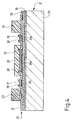
- Figure 4 is a sectional view of the sensor 21 on which the thicknesses of the various layers are not shown with their exact proportions in order to improve the clarity of the representation.
- the sensor 21 comprises a substrate 23, made of silicon for example, cut, after the appropriate photolithographic treatments, from a silicon wafer in the usual way in the technique of manufacturing semiconductor components.
- the substrate 23 is covered with an insulating layer 24, preferably made of silicon oxide (SiO2).
- This layer is in turn covered by another layer of insulator 25, made of silicon nitride (Si3N4) for example, layer on which is provided a configuration of connections 26 forming part of the connection means connecting the sensor itself 21 to the measurement circuit 22.
- the configuration of connections 26 is produced in the form of several polysilicon tracks, the shape of which will be described later.
- insulator 27 preferably made of silicon nitride (Si3N4), and in which several openings 28 are made, the connection configuration therefore being underlying the upper surface of the sensor.
- insulator 27 preferably made of silicon nitride (Si3N4), and in which several openings 28 are made, the connection configuration therefore being underlying the upper surface of the sensor.
- Each of these openings 28 has a determined shape and it receives a deposit of metal intended to constitute an electrode of the sensor 21.
- a first of these deposits forms the working electrode 29 of the sensor, preferably made of platinum.
- this working electrode 29 is circular in shape and is located in the center of the wafer above a polysilicon contact area 26a of the connection configuration 26.
- the contact zone 26a is connected to a polysilicon ribbon composed of the branches 26b and 26c, the branch 26c ending in a connection terminal 26d appearing on the upper surface of the third layer of insulator 27.
- a second metal deposit preferably also made of platinum, constitutes the counter-electrode 30 of the sensor 21.
- this counter-electrode is, in this example, of arcuate shape and extends practically all around the working electrode 29 above a polysilicon contact area 26e which is in contact with a conductive polysilicon tape whose branches 26f and 26g lead to a connection contact 26h also appearing on the surface upper layer of insulation 27.
- a third metallic deposit in silver covered with a very thin layer of silver chloride (AgCl), fills the third opening made in the insulating layer 27 and constitutes the reference electrode 31 of the sensor 21.
- the reference electrode is located above a polysilicon contact zone 26i which is connected to a polysilicon contact strip also, composed of two branches 26k and 261 leading to a contact 26m connection appearing on the upper surface of the insulating layer 27.
- the working electrode 29 is covered with a diffusion membrane 32 constituted by a hydrogel preferably made of poly-hydroxyethyl methacrylate (polyHEMA).
- polyHEMA poly-hydroxyethyl methacrylate
- the role of this membrane has been described in detail in the aforementioned article. Its main purpose is to avoid turbulence of the fluid to be analyzed above the working electrode 29 and it also makes it possible to prevent dirt from depositing thereon from the fluid to be measured.
- the chemical body which has just been indicated for the membrane is only one possible example, any other substance fulfilling the same role can be used. However, it is advantageous that the substance can be deposited using conventional photolithographic techniques and be polymerized by exposure, which is the case of poly-HEMA.
- the diffusion membrane 32 completely covers the working electrode 29 and that it even extends beyond the outer periphery of this electrode, which makes it possible to precisely define the area of the active surface of this electrode. Furthermore, it will be seen later that, when the sensor device according to the invention is used, the membrane 32 is exposed to the fluid to be analyzed by all of its exposed surface.
- Figures 3 and 4 also show that in the arrangement which has just been described can be added a seal 33 fixed around the arrangement of the electrodes of the sensor, on the upper surface of the insulating layer 27 , this lining can be formed by a polysiloxane, for example.
- the sensor 21 is connected to the measurement circuit 22 which forms a so-called "potentiostat" circuit (FIG. 3 shows a very simplified diagram thereof).
- the electrode working 29 is connected, via contact 26d, to an instrument 34 for measuring current which is also connected to ground.
- the reference electrode 31 is connected, via the contact 26m, to the inverting input of an operational amplifier 35, the direct input of which is connected to an adjustable voltage source 36 also connected to ground.
- This source 36 makes it possible to adjust the bias voltage U p present between the counter-electrode 30 and the working electrode 29.
- the senor 21 constitutes an electrochemical micro-cell, the electrochemical reaction with the fluid to be analyzed due to the presence of the redox substance causing the production of an electrochemical current I which is measurable by the measuring instrument 34.
- amperometric sensor device that has just been described is particularly suitable for measuring the chlorine content of drinking water, but it is understood that by choosing the metals of the electrodes of the sensor appropriately and the applied bias voltage using the same inventive concept at the working electrode, it would be possible to produce sensor devices capable of detecting in water or in fluids other than water, substances other than chlorine.
- FIG. 4 clearly shows the essentially circular arrangement of the electrodes 29, 30 and 31. This arrangement is very advantageous in that it leads to the best occupation of the surface of the substrate 23 for a maximum surface of the working electrode 29 whose area essentially determines the intensity of the measurement current.
- Figures 3 and 4 also show that only the surfaces of the membrane, of the counter electrode and of the reference electrode, useful for the measurement, are in contact with the fluid to be analyzed, to the exclusion of all the others.
- connection means which ensure the connection of the electrodes with the measurement circuit 22.
- the measurement area i.e. the area in which the electrodes are located
- the space above the rest of the substrate 23 and in particular that in which there are the visible contacts 26d, 26m and 26h which are used to make the electrical connection of the sensor 21 with the measurement circuit 22.
- no conductive element can interfere with the measurement by leakage currents or by d 'other disturbing causes, as was the case in the devices of the prior art.
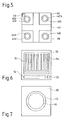
- FIGS 5, 6 and 7 show three different examples of electrode configurations that can be used on the substrate of the amperometric sensor.
- a substrate 40 comprises four elementary working electrodes 41a to 41d arranged at the four corners of the surface of the substrate and each covered by an elementary diffusion membrane 42a to 42d.
- a cross-shaped counter electrode 43 is also present on the substrate as is a reference electrode 44 which is placed near one of the corners of the substrate.
- each elementary membrane 42a to 42d is arranged in the same way and plays the same role as the diffusion membrane 32 of FIGS. 3 and 4 so that the same favorable results inherent in the invention are obtained here.
- a substrate 50 has a working electrode 51 in the form of a comb, the teeth of which extend parallel to one another towards one of the edges of the substrate and to which is contiguous a counterelectrode 52 which extends the along the opposite edge of the substrate 50.
- a reference electrode 53 is provided near one of the corners thereof.
- the working electrode 51 in the form of a comb is covered with a diffusion membrane 54.
- FIG. 7 shows another variant in which it is assumed that the counter electrode and the reference electrode are physically separated from the substrate 60 on which only one working electrode 61 has been provided, made from the same way as that of FIGS. 3 and 4.
- a diffusion membrane 62 covers the electrode 61 while projecting slightly from its outer periphery.
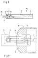
- Figures 8 and 9 show a first practical application of the amperometric sensor device according to the invention.
- a stylus 70 which can be connected by a cable 71 to a housing (not shown) comprising the measuring circuit, this assembly can be used to punctually measure the gas content d 'a fluid.
- a housing not shown
- Such an assembly could be made portable and easily handy for use when checking the chlorine content of the water of a swimming pool for example.
- a small pipe 72 forming a shield and made for example of aluminum, has at one of its ends a plug 73 in which a support 74 is mounted. On this support is fixed a sensor 75 of the type shown in 21 in FIGS. 3 and 4. As shown in FIG. 9, the support 74 is a printed circuit comprising three connection tracks 76 which, by means of soldered wires 77 are respectively connected to the three electrodes of the sensor.
- the seal 33 of FIGS. 3 and 4 is replaced by a bead 78 made of an insulating material which is placed on the substrate of the sensor 75, the electrodes of the sensor and in particular the working electrode covered with its diffusion membrane being exposed to the fluid to be analyzed when the stylus 70 is immersed therein.
- all the other conductive members, and in particular the contacts of connection ensuring the coupling with the measurement circuit are here covered by the bead 78.
- the aluminum pipe 72 is crossed by the cable 71 which is a three-wire connection establishing the connection between the support 74 and the measurement circuit (not shown in these figures).
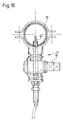
- FIG. 10 shows another way of using the amperometric sensor device according to the invention, for the purposes of continuous monitoring of the content of redox substance in a fluid circulating in a pipe 80.
- a support 81 comprising a tap 82 through which an amperometric sensor device of the type can be installed shown in Figures 8 and 9.
- the measuring device can easily be put in place in the piping or be removed by acting on the valve 82, without the fluid escaping from the piping.
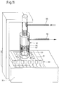
- FIG. 11 shows another way of using the sensor device according to the invention.
- its sensor the construction of which is identical to that of FIGS. 3 and 4
- the housing 90 is placed, for example on a support in the form of a bracket 91 to which is fixed a cylindrical nozzle 92 to two concentric pipes 93 and 94 to which are connected two pipes 95 and 96 respectively intended to be connected to inlet pipes and outlet (not shown) of the fluid to be analyzed.
- the external pipe 94 is in abutment on the gasket 33 which surrounds the active part of the sensor 21, while the end of the internal pipe 93 is slightly recessed with respect to the active surface of the diffusion membrane.
- the fluid to be analyzed can flow continuously from the inlet tubing 95, through the internal pipe 93, through the chamber provided above the diffusion membrane, and through the external pipe 94 towards the outlet tube 96.
- the amperometric device according to the invention can therefore deliver under these conditions a permanent signal which is a direct function of the content of redox substance in the fluid to be analyzed.
- the signal in question can be exploited in any suitable way, for example to be used to trigger a warning, when the content of redox substance exceeds an authorized value, to serve as real value in an adjustment loop intended to control the content of redox substance as a function of the deviation of this value from a set value etc.
Abstract
Description
La présente invention est relative à un dispositif capteur ampérométrique dont le capteur forme une cellule électrochimique miniature et qui est destiné à détecter ou à mesurer la teneur d'une substance oxydoréductible dans un fluide.The present invention relates to an amperometric sensor device, the sensor of which forms a miniature electrochemical cell and which is intended to detect or measure the content of an oxidoreducible substance in a fluid.
De tels dispositifs capteurs sont utilisés notamment, bien que non exclusivement, pour mesurer la teneur en chlore de l'eau potable.Such sensor devices are used in particular, although not exclusively, to measure the chlorine content of drinking water.
Un capteur utilisé dans ce but et son mécanisme de fonctionnement sont décrits dans un article de A.v.d.Berg et al., paru dans la revue "Transducers" 1991 - International Conference on Solid State Sensors and Actuators, page 233.A sensor used for this purpose and its operating mechanism are described in an article by A.v.d. Berg et al., Published in the journal "Transducers" 1991 - International Conference on Solid State Sensors and Actuators, page 233.
La construction du capteur décrit dans cet article est représentée aux figures 1 et 2 des dessins annexés.The construction of the sensor described in this article is shown in Figures 1 and 2 of the accompanying drawings.
Sur une plaquette de circuit imprimé 1 est fixé un substrat 2 en silicium découpé après des traitements photolithographiques appropriées d'une plaquette de silicium à l'image des techniques employées pour la fabrication des circuits intégrés et analogues.On a printed
Le substrat 2 est revêtu d'une couche 3 d'oxyde de silicium (Si0₂) sur laquelle est déposée une couche 4 d'un isolant tel que l'oxyde d'aluminium (Al₂0₃).The
Le capteur connu comprend également trois électrodes 5, 6 et 7 formant respectivement une électrode de travail, une contre-électrode et une électrode de référence qui sont réalisées sous la forme de rubans déposés, également par de techniques photolithographiques, sur la couche d'isolant 4.The known sensor also comprises three
Les électrodes 5, 6 et 7 sont ensuite recouvertes d'une membrane de diffusion 8 formée par une matière organique telle que l'hydrogel poly HEMA ou analogue (voir l'article précité). Cette membrane, déposée et polymérisée de préférence par des techniques photolithographiques, est destinée à garantir une mise en contact uniforme et sans turbulences du fluide à analyser avec les électrodes.The
Celles-ci sont reliées individuellement à des contacts 9 prévus sur le circuit imprimé 1, au moyen de fils soudés 10, une encapsulation 11 étant ensuite placée sur l'ensemble pour le protéger vis-à-vis du fluide à analyser, à l'exception, bien entendu, d'une partie de la membrane de diffusion 8 et, par conséquent des électrodes 5, 6 et 7, afin que le fonctionnement électrochimique puisse avoir lieu.These are individually connected to
Il est à noter que, dans le cas où il s'agit de mesurer la teneur en chlore dans l'eau, les électrodes 5 et 6 sont réalisées en platine et que l'électrode de référence 7 est en argent revêtue d'une faible couche de chlorure d'argent (AgCl).It should be noted that, in the case where it is a question of measuring the chlorine content in the water, the
Le dispositif capteur ampérométrique comportant ce capteur combiné à un circuit dit "potentiostat", qui est connecté à ce dernier, permet d'évaluer la teneur en substance oxydoréductible dans un fluide (par exemple la teneur en chlore dans l'eau) en mesurant le courant électrique généré à l'électrode de travail 5 du capteur.The amperometric sensor device comprising this sensor combined with a so-called "potentiostat" circuit, which is connected to the latter, makes it possible to evaluate the content of redox substance in a fluid (for example the content of chlorine in water) by measuring the electric current generated at the working
Le capteur ainsi conçu, bien que fonctionnant de façon satisfaisante sur le plan du principe, présente certains inconvénients.The sensor thus designed, although operating satisfactorily in principle, has certain drawbacks.
En effet, si les dimensions des électrodes (qui ont une longueur de quelques millimètres seulement et une largeur de l'ordre du dixième de millimètre) peuvent être déterminées avec une bonne précision grâce aux techniques photolithographiques, il n'en est pas de même de celles de l'encapsulation 11. Comme cette encapsulation 11 doit isoler les parties conductrices non-actives des électrodes 5, 6 et 7 du fluide à analyser, elle doit de préférence déborder légèrement sur la couche d'hydrogel constituant la membrane de diffusion 8. Dans l'exemple représenté, la zone de débordement est indiqué par la distance d et présente un bord avant 12 dont la localisation exacte par rapport à la membrane de diffusion est difficilement maîtrisable avec précision. En d'autres termes, la distance d peut varier dans des proportions importantes d'un capteur à l'autre. Or, cette distance détermine en définitive l'aire de la zone exposée au fluide et donc la surface de mesure active à laquelle le courant électrochimique est engendré, si bien que l'intensité de ce courant, toutes choses égales par ailleurs, différera d'un capteur à l'autre.Indeed, if the dimensions of the electrodes (which have a length of only a few millimeters and a width of the order of a tenth of a millimeter) can be determined with good precision thanks to photolithographic techniques, it is not the same for those of
Par ailleurs, pour pouvoir engendrer un courant électrochimique appréciable, on souhaite que cette surface active soit aussi grande que possible pour des dimensions données d'un capteur. Dans ces conditions, le bord avant 12 de l'encapsulation doit se trouver le plus près possible du bord arrière 13 de la membrane 8. Mais alors, il se peut que le fluide à analyser fuie sous ce bord et provoque la production de courants de fuite entre les parties des rubans des électrodes situées en arrière de la membrane 8 et ne devant donc normalement pas participer à la production du courant électrochimique de mesure.Furthermore, in order to be able to generate an appreciable electrochemical current, it is desired that this active surface be as large as possible for given dimensions of a sensor. Under these conditions, the
Enfin, l'inconvénient le plus important du dispositif antérieur est que l'aire de la surface active de l'électrode de travail ne peut être déterminée avec précision de sorte que l'étalonnage précis de chaque capteur est nécessaire et que l'interface entre la membrane et l'encapsulation est une source de perturbations.Finally, the most important drawback of the prior device is that the area of the active surface of the working electrode cannot be determined with precision so that precise calibration of each sensor is necessary and that the interface between the membrane and encapsulation is a source of disturbance.
L'invention a pour but de remédier aux inconvénients du dispositif capteur décrit dans l'article précité.The object of the invention is to remedy the drawbacks of the sensor device described in the above-mentioned article.
Elle a donc pour objet un dispositif capteur ampérométrique, notamment pour la mesure de la teneur d'une substance oxydoréductible dans un fluide, comprenant en combinaison un capteur ayant une structure planaire obtenue par des techniques photolithographiques et un circuit de mesure pour mesurer l'intensité du courant électrochimique engendré par ledit capteur, ladite structure comprenant
- un substrat isolant
- un jeu d'électrodes composé d'au moins une électrode de travail, d'une contre-électrode et d'une électrode de référence, au moins ladite électrode de travail étant configurée sur ledit substrat isolant,
- une membrane de diffusion déposée sur au moins une partie desdites électrodes, et
- des moyens de connexion pour relier les électrodes audit circuit de mesure,
ledit dispositif capteur ampérométrique étant caractérisé en ce que - la partie conductrice de ladite électrode de travail, située à la surface dudit substrat est entièrement couverte par ladite membrane de diffusion qui déborde de cette électrode par toute sa zone périphérique, et
- en ce que ladite membrane est entièrement exposée, pour qu'au cours du fonctionnement du dispositif, elle soit en contact avec le fluide à analyser par toute sa surface.
- an insulating substrate
- a set of electrodes composed of at least one working electrode, a counter electrode and a reference electrode, at least said working electrode being configured on said insulating substrate,
- a diffusion membrane deposited on at least part of said electrodes, and
- connection means for connecting the electrodes to said measurement circuit,
said amperometric sensor device being characterized in that - the conductive part of said working electrode, located on the surface of said substrate, is entirely covered by said diffusion membrane which extends beyond this electrode through its entire peripheral zone, and
- in that said membrane is fully exposed, so that during operation of the device, it is in contact with the fluid to be analyzed through its entire surface.
Il résulte de ces caractéristiques que l'aire de la surface active de l'électrode de travail est uniquement définie par l'aire de sa partie conductrice à la surface du substrat, aire dont les dimensions sont déterminables avec une grande précision du fait qu'elles sont définies au cours du procédé de photolithographie mis en oeuvre pour créer l'électrode à la surface du substrat.It follows from these characteristics that the area of the active surface of the working electrode is only defined by the area of its conductive part on the surface of the substrate, an area whose dimensions can be determined with great precision because they are defined during the photolithography process used to create the electrode on the surface of the substrate.
Comme par ailleurs la membrane de diffusion déborde de l'électrode de travail par toute sa zone périphérique, toute quantité de courant électrochimique engendrée à la surface de l'électrode de travail peut être prise en compte pour la mesure à l'exclusion de tout courant de fuite.As, moreover, the diffusion membrane extends beyond the working electrode through its entire peripheral zone, any quantity of electrochemical current generated at the surface of the working electrode can be taken into account for the measurement to the exclusion of any leakage current.
Suivant une autre caractéristique importante de l'invention, lesdits moyens de connexion comportent au moins un conducteur relié à ladite électrode de travail et passant dans ladite structure à un niveau sous-jacent à la surface active de celle-ci, en s'étendant au moins au-delà de la périphérie de ladite membrane de diffusion.According to another important characteristic of the invention, said connection means comprise at least one conductor connected to said working electrode and passing through said structure at a level underlying the active surface thereof, extending to the at least beyond the periphery of said diffusion membrane.
Cette caractéristique permet également d'éviter que des parties conductrices du capteur autres que celles formant son électrode de travail ne participent à la production du courant électrochimique, les organes de connexion menant à partir de la périphérie de la membrane de diffusion vers les bornes de connexion du capteur pouvant facilement être recouverts par l'encapsulation qui, dans ce cas, ne pourra pas influencer l'étendue de la surface active du capteur.This characteristic also makes it possible to prevent conductive parts of the sensor other than those forming its working electrode from participating in the production of the electrochemical current, the connection members leading from the periphery of the diffusion membrane towards the connection terminals. of the sensor which can easily be covered by the encapsulation which, in this case, will not be able to influence the extent of the active surface of the sensor.
D'autres caractéristiques et avantages de l'invention apparaîtront au cours de la description qui va suivre, donnée uniquement à titre d'exemple et faite en se référant aux dessins annexés sur lesquels :
- la figure 1 est une vue en coupe schématique d'un dispositif capteur ampérométrique réalisé selon la technique antérieure;
- la figure 2 est une vue en coupe prise selon la ligne II - II de la figure 1;
- la figure 3 est une vue en plan d'un capteur ampérométrique combiné à un circuit de mesure pour former le dispositif capteur selon l'invention;
- la figure 4 est une vue en coupe schématique prise selon la ligne IV - IV de la figure 3;
- les figures 5, 6 et 7 sont des vues schématiques en plan de trois autres configurations du capteur pouvant être utilisé dans le dispositif capteur suivant l'invention;
- la figure 8 montre une vue schématique en coupe axiale d'un capteur selon un montage pratique;
- la figure 9 est une vue, à plus grande échelle que celle de la figure 8, du capteur utilisé dans le dispositif de la figure 8, la vue étant prise selon la ligne IX - IX de celle-ci;
- la figure 10 montre un mode d'utilisation du capteur des figures 8 et 9; et
- la figure 11 montre une autre application du dispositif capteur selon l'invention.
- Figure 1 is a schematic sectional view of an amperometric sensor device produced according to the prior art;
- Figure 2 is a sectional view taken along the line II - II of Figure 1;
- Figure 3 is a plan view of an amperometric sensor combined with a measurement circuit to form the sensor device according to the invention;
- Figure 4 is a schematic sectional view taken along the line IV - IV of Figure 3;
- Figures 5, 6 and 7 are schematic plan views of three other configurations of the sensor that can be used in the sensor device according to the invention;
- FIG. 8 shows a schematic view in axial section of a sensor according to a practical assembly;
- Figure 9 is a view, on a larger scale than that of Figure 8, of the sensor used in the device of Figure 8, the view being taken along the line IX - IX thereof;
- Figure 10 shows a mode of use of the sensor of Figures 8 and 9; and
- Figure 11 shows another application of the sensor device according to the invention.
On va maintenant se référer aux figures 3 et 4 qui représentent un dispositif capteur ampérométrique 20 conçu selon le mode de réalisation préféré de l'invention. Ce dispositif comprend tout d'abord le capteur proprement dit 21 ainsi qu'un circuit de mesure 22 qui est représenté sur la figure 3 selon un schéma extrêmement simplifié. La figure 4 est une vue en coupe du capteur 21 sur laquelle les épaisseurs des diverses couches ne sont pas représentées avec leurs proportions exactes afin d'améliorer la clarté de la représentation.We will now refer to Figures 3 and 4 which show an
Le capteur 21 comporte un substrat 23, en silicium par exemple, découpé, après les traitements photolithographiques appropriés, d'une plaquette de silicium à la façon habituelle dans la technique de fabrication des composants semi-conducteurs. Le substrat 23 est recouvert d'une couche d'isolant 24, réalisé de préférence en oxyde de silicium (SiO₂). Cette couche est recouverte à son tour par une autre couche d'isolant 25, en nitrure de silicium (Si₃N₄) par exemple, couche sur laquelle est apportée une configuration de connexions 26 formant une partie des moyens de connexion reliant le capteur proprement dit 21 au circuit de mesure 22. La configuration de connexions 26 est réalisée sous la forme de plusieurs pistes en polysilicium dont la forme va être décrite par la suite. Elle est recouverte par une troisième couche d'isolant 27 réalisée de préférence en nitrure de silicium (Si₃N₄), et dans laquelle sont pratiquées plusieurs ouvertures 28, la configuration de connexion étant donc sous-jacente à la surface supérieure du capteur. Chacune de ces ouvertures 28 présente une forme déterminée et elle reçoit un dépôt de métal destiné à constituer une électrode du capteur 21.The
Ainsi, un premier de ces dépôts forme l'électrode de travail 29 du capteur, réalisée de préférence en platine. Dans l'exemple représenté, cette électrode de travail 29 est de forme circulaire et se trouve au centre de la plaquette au-dessus d'une zone de contact 26a en polysilicium de la configuration de connexion 26. Comme représenté sur la figure 3, la zone de contact 26a est reliée à un ruban en polysilicium composé des branches 26b et 26c, la branche 26c se terminant par une borne de connexion 26d apparaissant à la surface supérieure de la troisième couche d'isolant 27.Thus, a first of these deposits forms the working
Un second dépôt de métal, également en platine de préférence, constitue la contre-électrode 30 du capteur 21. Comme on le voit également sur la figure 3, cette contre-électrode est, dans cet exemple, de forme arquée et s'étend pratiquement tout autour de l'électrode de travail 29 au-dessus d'une zone de contact en polysilicium 26e qui est en contact d'un ruban conducteur en polysilicium dont les branches 26f et 26g mènent à un contact de connexion 26h apparaissant également à la surface supérieure de la couche d'isolant 27.A second metal deposit, preferably also made of platinum, constitutes the counter-electrode 30 of the
Enfin, un troisième dépôt métallique, en argent recouvert d'une très mince couche de chlorure d'argent (AgCl), remplit la troisième ouverture pratiquée dans la couche d'isolant 27 et constitue l'électrode de référence 31 du capteur 21. L'électrode de référence est située audessus d'une zone de contact 26i en polysilicium qui est connectée à un ruban de contact en polysilicium également, composée de deux branches 26k et 261 menant à un contact de connexion 26m apparaissant à la surface supérieure de la couche d'isolant 27.Finally, a third metallic deposit, in silver covered with a very thin layer of silver chloride (AgCl), fills the third opening made in the insulating
L'électrode de travail 29 est recouverte d'une membrane de diffusion 32 constituée par un hydrogel fait de préférence en poly-hydroxyéthyle-métacrylate (polyHEMA). Le rôle de cette membrane a été décrit en détail dans l'article précité. Elle a essentiellement pour but d'éviter les turbulences du fluide à analyser au-dessus de l'électrode de travail 29 et elle permet également d'éviter aux salissures de s'y déposer à partir du fluide à mesurer. Le corps chimique que l'on vient d'indiquer pour la membrane n'est qu'un exemple possible, toute autre substance remplissant le même rôle pouvant être utilisée. Toutefois, il est avantageux que la substance puisse être déposée à l'aide des techniques photolithographiques classiques et être polymérisée par insolation, ce qui est le cas du poly-HEMA.The working
On notera que, selon une caractéristique essentielle de l'invention, la membrane de diffusion 32 couvre entièrement l'électrode de travail 29 et qu'elle déborde même de la périphérie extérieure de cette électrode ce qui permet de définir avec précision l'aire de la surface active de cette électrode. Par ailleurs, on verra par la suite que, lorsque le dispositif capteur selon l'invention est utilisé, la membrane 32 est exposée au fluide à analyser par la totalité de sa surface découverte.It will be noted that, according to an essential characteristic of the invention, the
Les figures 3 et 4 montrent également qu'à la disposition que l'on vient de décrire peut être adjointe une garniture d'étanchéité 33 fixée autour de l'agencement des électrodes du capteur, sur la surface supérieure de la couche d'isolant 27, cette garniture pouvant être formée par un polysiloxane, par exemple.Figures 3 and 4 also show that in the arrangement which has just been described can be added a
En se référant plus particulièrement à la figure 3, on voit que le capteur 21 est raccordé au circuit de mesure 22 qui forme un montage dit "potentiostat" (la figure 3 en montre un schéma très simplifié). L'électrode de travail 29 est connectée, par l'intermédiaire du contact 26d, à un instrument 34 de mesure de courant qui est par ailleurs raccordé à la masse. L'électrode de référence 31 est raccordée, par l'intermédiaire du contact 26m, à l'entrée inverseuse d'un amplificateur opérationnel 35 dont l'entrée directe est connectée à une source de tension réglable 36 raccordée par ailleurs à la masse. Cette source 36 permet de régler la tension de polarisation Up présente entre la contre-électrode 30 et l'électrode de travail 29.Referring more particularly to FIG. 3, it can be seen that the
Ainsi, le capteur 21 constitue une micro-cellule électrochimique, la réaction électrochimique avec le fluide à analyser du fait de la présence de la substance oxydoréductible provoquant la production d'un courant électrochimique I qui est mesurable par l'instrument de mesure 34.Thus, the
Le dispositif capteur ampérométrique que l'on vient de décrire est particulièrement approprié pour la mesure de la teneur en chlore de l'eau potable, mais il est bien entendu qu'en choisissant convenablement les métaux des électrodes du capteur et la tension de polarisation appliquée à l'électrode de travail, l'on pourrait, en partant du même concept inventif, réaliser des dispositifs capteurs capables de détecter dans l'eau ou dans d'autres fluides que l'eau, d'autres substances que le chlore.The amperometric sensor device that has just been described is particularly suitable for measuring the chlorine content of drinking water, but it is understood that by choosing the metals of the electrodes of the sensor appropriately and the applied bias voltage using the same inventive concept at the working electrode, it would be possible to produce sensor devices capable of detecting in water or in fluids other than water, substances other than chlorine.
La figure 4 fait apparaître clairement la disposition essentiellement circulaire des électrodes 29, 30 et 31. Cette disposition est très avantageuse en ce qu'elle conduit à la meilleure occupation de la surface du substrat 23 pour une surface maximale de l'électrode de travail 29 dont l'aire détermine essentiellement l'intensité du courant de mesure.FIG. 4 clearly shows the essentially circular arrangement of the
Cependant, les spécialistes dans la technique concernée comprendront que la configuration obtenue par photolithographie sur le substrat 23 peut être différente de celle représentée aux figures 3 et 4, pourvu bien entendu que les caractéristiques essentielles de l'invention soient respectées à savoir, d'une part, la couverture complète par la membrane de diffusion 32 de l'électrode de travail 29 et, d'autre part, l'exposition totale de la membrane de diffusion 32 au fluide à analyser.However, those skilled in the art will understand that the configuration obtained by photolithography on the
A titre indicatif seulement, les dimensions et épaisseurs suivantes sont appropriées pour la réalisation du dispositif capteur que l'on vient de décrire
Les figures 3 et 4 font également apparaître que seules les surfaces de la membrane, de la contre-électrode et de l'électrode de référence, utiles pour la mesure sont en contact avec le fluide à analyser, à l'exclusion de tous les autres moyens de connexion qui assurent la liaison des électrodes avec le circuit de mesure 22. En effet, comme on le verra par la suite, grâce à la présence de la garniture d'étanchéité 33, il est facilement possible de rendre étanche la zone de mesure (c'est-à-dire la zone dans laquelle se trouvent les électrodes), de l'espace au-dessus du reste du substrat 23, et notamment celui dans lequel se trouvent les contacts apparents 26d, 26m et 26h qui sont utilisés pour réaliser la connexion électrique du capteur 21 avec le circuit de mesure 22. Ainsi, aucun élément conducteur ne peut venir perturber la mesure par des courants de fuite ou par d'autres causes perturbatrices, comme cela était le cas dans les dispositifs de la technique antérieure.Figures 3 and 4 also show that only the surfaces of the membrane, of the counter electrode and of the reference electrode, useful for the measurement, are in contact with the fluid to be analyzed, to the exclusion of all the others. connection means which ensure the connection of the electrodes with the
Les figures 5, 6 et 7 représentent trois exemples différents de configurations d'électrodes pouvant être utilisées sur le substrat du capteur ampérométrique.Figures 5, 6 and 7 show three different examples of electrode configurations that can be used on the substrate of the amperometric sensor.
Sur la figure 5, un substrat 40 comporte quatre électrodes élémentaires de travail 41a à 41d disposées aux quatre coins de la surface du substrat et recouvertes chacune par une membrane élémentaire de diffusion 42a à 42d. Une contre-électrode 43 en forme de croix est également présente sur le substrat de même qu'une électrode de référence 44 qui est placée près de l'un des angles du substrat. La technique de fabrication d'un tel capteur est très analogue à celle à l'aide de laquelle est réalisé le capteur représenté sur les figures 3 et 4 et on n'y reviendra donc pas de nouveau.In FIG. 5, a
On peut noter simplement que dans cette variante de l'invention, chaque membrane élémentaire 42a à 42d est agencée de la même façon et joue le même rôle que la membrane de diffusion 32 des figures 3 et 4 de sorte que les même résultats favorables inhérents à l'invention sont obtenus ici.It can simply be noted that in this variant of the invention, each
Sur la figure 6, un substrat 50 présente une électrode de travail 51 en forme de peigne dont les dents s'étendent parallèlement les unes aux autres vers l'un des bords du substrat et à laquelle est contiguë une contreélectrode 52 qui s'étend le long du bord opposé du substrat 50. Une électrode de référence 53 est prévue près de l'un des angles de celui-ci. L'électrode de travail 51 en forme de peigne est recouverte d'une membrane de diffusion 54.In FIG. 6, a
Sur la figure 7, on a représenté une autre variante dans laquelle il est supposé que la contre-électrode et l'électrode de référence sont physiquement séparées du substrat 60 sur lequel on n'a prévu qu'une électrode de travail 61 réalisée de la même façon que celle des figures 3 et 4. Une membrane de diffusion 62 recouvre l'électrode 61 en débordant légèrement de sa périphérie extérieure.FIG. 7 shows another variant in which it is assumed that the counter electrode and the reference electrode are physically separated from the
Les figures 8 et 9 montrent une première application pratique du dispositif capteur ampérométrique selon l'invention.Figures 8 and 9 show a first practical application of the amperometric sensor device according to the invention.
Il s'agit, comme représenté sur la figure 8, d'un stylet 70 pouvant être raccordé par un câble 71 à un boîtier (non représenté) comportant le circuit de mesure, cet ensemble pouvant être utilisé pour mesurer ponctuellement la teneur en gaz d'un fluide. Un tel ensemble pourrait être rendu portable et facilement maniable pour être utilisé lors de la vérification de la teneur en chlore de l'eau d'une piscine par exemple.It is, as shown in Figure 8, a
Plus précisément, un petit tuyau 72, formant blindage et réalisé par exemple en aluminium, comporte à l'une des ses extrémités un bouchon 73 dans lequel est monté un support 74. Sur ce support est fixé un capteur 75 du type de celui représenté en 21 sur les figures 3 et 4. Comme représenté à la figure 9, le support 74 est un circuit imprimé comportant trois pistes de connexion 76 qui, par l'intermédiaire de fils soudés 77 sont respectivement reliés aux trois électrodes du capteur.More specifically, a
Comme on peut le constater, dans ce cas, la garniture d'étanchéité 33 des figures 3 et 4 est remplacée par un bourrelet 78 en une matière isolante qui est placé sur le substrat du capteur 75, les électrodes du capteur et en particulier l'électrode de travail recouverte de sa membrane de diffusion étant exposée au fluide à analyser lorsque le stylet 70 y est plongé. En revanche, tous les autres organes conducteurs, et notamment les contacts de connexion assurant le couplage avec le circuit de mesure sont ici recouverts par le bourrelet 78.As can be seen, in this case, the
Le tuyau d'aluminium 72 est traversé par le câble 71 qui est une connexion trifilaire établissant la liaison entre le support 74 et le circuit de mesure (non représenté sur ces figures).The
La figure 10 montre une autre façon d'utiliser le dispositif capteur ampérométrique suivant l'invention, à des fins de contrôle continu de la teneur en substance oxydoréductible dans un fluide en circulation dans une tuyauterie 80. Sur cette tuyauterie 80 est fixé un support 81 comprenant un robinet 82 à travers lequel l'on peut mettre en place un dispositif capteur ampèrométrique du type
représenté sur les figures 8 et 9. Le dispositif de mesure peut facilement être mis en place dans la tuyauterie ou en être ôté en agissant sur le robinet 82, sans que le fluide ne s'échappe de la tuyauterie.FIG. 10 shows another way of using the amperometric sensor device according to the invention, for the purposes of continuous monitoring of the content of redox substance in a fluid circulating in a
shown in Figures 8 and 9. The measuring device can easily be put in place in the piping or be removed by acting on the valve 82, without the fluid escaping from the piping.
La figure 11 montre une autre façon d'utiliser le dispositif capteur suivant l'invention. Dans ce cas, on a encapsulé son capteur dont la construction est identique à celle des figures 3 et 4, dans un boîtier normalisé 90 du type DIL à seize broches utilisé habituellement pour les composants de circuit intégré. Le boîtier 90 est placé, par exemple sur un support en forme de potence 91 auquel est fixé un ajutage cylindrique 92 à deux canalisations concentriques 93 et 94 auxquelles sont respectivement branchées deux tubulures 95 et 96 destinées à être connectées à des tuyaux d'entrée et de sortie (non représentés) du fluide à analyser.FIG. 11 shows another way of using the sensor device according to the invention. In this case, its sensor, the construction of which is identical to that of FIGS. 3 and 4, has been encapsulated in a
Comme on peut le constater sur la figure 11, la canalisation externe 94 est en appui sur la garniture d'étanchéité 33 qui entoure la partie active du capteur 21, tandis que l'extrémité de la canalisation interne 93 est légèrement en retrait par rapport à la surface active de la membrane de diffusion.As can be seen in FIG. 11, the
Ainsi, le fluide à analyser peut s'écouler en continu de la tubulure d'entrée 95, à travers la canalisation interne 93, à travers la chambre ménagée au-dessus de la membrane de diffusion, et à travers la canalisation externe 94 vers la tubulure de sortie 96. Le dispositif ampèrométrique suivant l'invention peut donc délivrer dans ces conditions un signal permanent qui est une fonction directe de la teneur en substance oxydoréductible dans le fluide à analyser. Bien entendu, le signal en question peut être exploité de toute manière appropriée, par exemple servir pour déclencher un avertissement, lorsque la teneur en substance oxydoréductible dépasse une valeur autorisée, pour servir de valeur réelle dans une boucle de réglage destinée à commander la teneur en substance oxydoréductible en fonction de l'écart de cette valeur par rapport à une valeur de consigne etc.Thus, the fluid to be analyzed can flow continuously from the
Claims (10)
ledit dispositif capteur ampérométrique étant caractérisé en ce que
said amperometric sensor device being characterized in that
Applications Claiming Priority (2)
| Application Number | Priority Date | Filing Date | Title |
|---|---|---|---|
| FR9210740A FR2695481B1 (en) | 1992-09-07 | 1992-09-07 | Amperometric measurement device comprising an electrochemical sensor. |
| FR9210740 | 1992-09-07 |
Publications (2)
| Publication Number | Publication Date |
|---|---|
| EP0586982A1 true EP0586982A1 (en) | 1994-03-16 |
| EP0586982B1 EP0586982B1 (en) | 1998-07-08 |
Family
ID=9433330
Family Applications (1)
| Application Number | Title | Priority Date | Filing Date |
|---|---|---|---|
| EP93113710A Expired - Lifetime EP0586982B1 (en) | 1992-09-07 | 1993-08-27 | Amperometric measuring system with an electrochemical sensor |
Country Status (8)
| Country | Link |
|---|---|
| US (1) | US5393399A (en) |
| EP (1) | EP0586982B1 (en) |
| JP (1) | JP3292938B2 (en) |
| AT (1) | ATE168195T1 (en) |
| CA (1) | CA2105510C (en) |
| DE (1) | DE69319516T2 (en) |
| ES (1) | ES2121041T3 (en) |
| FR (1) | FR2695481B1 (en) |
Cited By (2)
| Publication number | Priority date | Publication date | Assignee | Title |
|---|---|---|---|---|
| EP2241882A1 (en) | 2009-04-15 | 2010-10-20 | Neroxis SA | Amperometric electrochemical sensor and manufacturing method |
| WO2013014187A1 (en) * | 2011-07-25 | 2013-01-31 | Veolia Water Solutions & Technologies Support | Device for measuring the free chloride content of water |
Families Citing this family (37)
| Publication number | Priority date | Publication date | Assignee | Title |
|---|---|---|---|---|
| AUPN239395A0 (en) * | 1995-04-12 | 1995-05-11 | Memtec Limited | Method of defining an electrode area |
| AUPN363995A0 (en) | 1995-06-19 | 1995-07-13 | Memtec Limited | Electrochemical cell |
| US6413410B1 (en) | 1996-06-19 | 2002-07-02 | Lifescan, Inc. | Electrochemical cell |
| US6521110B1 (en) | 1995-11-16 | 2003-02-18 | Lifescan, Inc. | Electrochemical cell |
| US6638415B1 (en) * | 1995-11-16 | 2003-10-28 | Lifescan, Inc. | Antioxidant sensor |
| US6863801B2 (en) | 1995-11-16 | 2005-03-08 | Lifescan, Inc. | Electrochemical cell |
| AUPN661995A0 (en) * | 1995-11-16 | 1995-12-07 | Memtec America Corporation | Electrochemical cell 2 |
| DE19621997C1 (en) * | 1996-05-31 | 1997-07-31 | Siemens Ag | Electrochemical sensor e.g. for gas determination |
| US6110354A (en) * | 1996-11-01 | 2000-08-29 | University Of Washington | Microband electrode arrays |
| US6632349B1 (en) * | 1996-11-15 | 2003-10-14 | Lifescan, Inc. | Hemoglobin sensor |
| AUPO585797A0 (en) * | 1997-03-25 | 1997-04-24 | Memtec America Corporation | Improved electrochemical cell |
| FR2764385B1 (en) * | 1997-06-06 | 1999-07-16 | Commissariat Energie Atomique | MICROSYSTEM FOR ANALYZING LIQUIDS WITH INTEGRATED CUP |
| AUPO855897A0 (en) * | 1997-08-13 | 1997-09-04 | Usf Filtration And Separations Group Inc. | Automatic analysing apparatus II |
| US6475360B1 (en) | 1998-03-12 | 2002-11-05 | Lifescan, Inc. | Heated electrochemical cell |
| US6878251B2 (en) * | 1998-03-12 | 2005-04-12 | Lifescan, Inc. | Heated electrochemical cell |
| US6652734B1 (en) | 1999-03-16 | 2003-11-25 | Lifescan, Inc. | Sensor with improved shelf life |
| US6592731B1 (en) | 1999-09-23 | 2003-07-15 | Ceramphysics, Inc. | Amperometric oxygen sensor |
| US6824661B2 (en) | 1999-09-23 | 2004-11-30 | Ceramphysics, Inc. | Combined oxygen and NOx sensor |
| FI113089B (en) | 1999-10-06 | 2004-02-27 | Liqum Oy | Method for analyzing papermaking process and electrochemical sensor for analyzing liquid |
| RU2278612C2 (en) * | 2000-07-14 | 2006-06-27 | Лайфскен, Инк. | Immune sensor |
| US6444115B1 (en) | 2000-07-14 | 2002-09-03 | Lifescan, Inc. | Electrochemical method for measuring chemical reaction rates |
| GB0121669D0 (en) * | 2001-09-10 | 2001-10-31 | Sensalyse Holdings Ltd | Electrode |
| AU2002340079A1 (en) | 2001-10-10 | 2003-04-22 | Lifescan Inc. | Electrochemical cell |
| US20060134713A1 (en) | 2002-03-21 | 2006-06-22 | Lifescan, Inc. | Biosensor apparatus and methods of use |
| US20030180814A1 (en) * | 2002-03-21 | 2003-09-25 | Alastair Hodges | Direct immunosensor assay |
| JP4758752B2 (en) * | 2005-12-16 | 2011-08-31 | 日本電信電話株式会社 | pH electrode |
| US8529751B2 (en) | 2006-03-31 | 2013-09-10 | Lifescan, Inc. | Systems and methods for discriminating control solution from a physiological sample |
| US8778168B2 (en) * | 2007-09-28 | 2014-07-15 | Lifescan, Inc. | Systems and methods of discriminating control solution from a physiological sample |
| US8513371B2 (en) * | 2007-12-31 | 2013-08-20 | Bridgestone Corporation | Amino alkoxy-modified silsesquioxanes and method of preparation |
| US8603768B2 (en) | 2008-01-17 | 2013-12-10 | Lifescan, Inc. | System and method for measuring an analyte in a sample |
| US8551320B2 (en) | 2008-06-09 | 2013-10-08 | Lifescan, Inc. | System and method for measuring an analyte in a sample |
| US8444835B2 (en) * | 2010-09-09 | 2013-05-21 | Intel Corporation | Electronic and fluidic interface |
| DE102014112972A1 (en) * | 2013-09-12 | 2015-03-12 | Endress + Hauser Conducta Gesellschaft für Mess- und Regeltechnik mbH + Co. KG | Measuring diaphragm for an optochemical or amperometric sensor |
| US11268927B2 (en) | 2016-08-30 | 2022-03-08 | Analog Devices International Unlimited Company | Electrochemical sensor, and a method of forming an electrochemical sensor |
| US10620151B2 (en) | 2016-08-30 | 2020-04-14 | Analog Devices Global | Electrochemical sensor, and a method of forming an electrochemical sensor |
| DE102016123700A1 (en) * | 2016-12-07 | 2018-06-07 | Endress+Hauser Conducta Gmbh+Co. Kg | Sensor for determining a measured variable dependent on a concentration of reactive oxygen species |
| US11022579B2 (en) | 2018-02-05 | 2021-06-01 | Analog Devices International Unlimited Company | Retaining cap |
Citations (6)
| Publication number | Priority date | Publication date | Assignee | Title |
|---|---|---|---|---|
| US4571292A (en) * | 1982-08-12 | 1986-02-18 | Case Western Reserve University | Apparatus for electrochemical measurements |
| WO1988009500A1 (en) * | 1987-05-26 | 1988-12-01 | Transducer Research, Inc. | Electrochemical micro sensor |
| EP0299780A2 (en) * | 1987-07-15 | 1989-01-18 | Sri International | Surface type microelectronic gas and vapor sensor |
| EP0299779A2 (en) * | 1987-07-15 | 1989-01-18 | Sri International | Fast response time microsensors for gaseous and vaporous species |
| EP0328640A1 (en) * | 1987-07-28 | 1989-08-23 | Daikin Industries, Limited | Combustible gas sensor |
| US4948490A (en) * | 1988-02-19 | 1990-08-14 | Honeywell Inc. | Tetraalkylammonium ion solid electrolytes |
Family Cites Families (5)
| Publication number | Priority date | Publication date | Assignee | Title |
|---|---|---|---|---|
| US3791953A (en) * | 1972-10-31 | 1974-02-12 | Atomic Energy Commission | Self-sealing electrochemical oxygen meter |
| US4694834A (en) * | 1986-03-31 | 1987-09-22 | Medtronic, Inc. | Gas sensor |
| US4851088A (en) * | 1987-03-05 | 1989-07-25 | Honeywell Inc. | Electrochemical detection of carbon dioxide |
| WO1989009397A1 (en) * | 1988-03-31 | 1989-10-05 | Matsushita Electric Industrial Co., Ltd. | Biosensor and process for its production |
| GB8817421D0 (en) * | 1988-07-21 | 1988-08-24 | Medisense Inc | Bioelectrochemical electrodes |
-
1992
- 1992-09-07 FR FR9210740A patent/FR2695481B1/en not_active Expired - Fee Related
-
1993
- 1993-08-27 ES ES93113710T patent/ES2121041T3/en not_active Expired - Lifetime
- 1993-08-27 AT AT93113710T patent/ATE168195T1/en not_active IP Right Cessation
- 1993-08-27 EP EP93113710A patent/EP0586982B1/en not_active Expired - Lifetime
- 1993-08-27 DE DE69319516T patent/DE69319516T2/en not_active Expired - Fee Related
- 1993-09-03 CA CA002105510A patent/CA2105510C/en not_active Expired - Fee Related
- 1993-09-07 US US08/117,872 patent/US5393399A/en not_active Expired - Fee Related
- 1993-09-07 JP JP24623993A patent/JP3292938B2/en not_active Expired - Fee Related
Patent Citations (6)
| Publication number | Priority date | Publication date | Assignee | Title |
|---|---|---|---|---|
| US4571292A (en) * | 1982-08-12 | 1986-02-18 | Case Western Reserve University | Apparatus for electrochemical measurements |
| WO1988009500A1 (en) * | 1987-05-26 | 1988-12-01 | Transducer Research, Inc. | Electrochemical micro sensor |
| EP0299780A2 (en) * | 1987-07-15 | 1989-01-18 | Sri International | Surface type microelectronic gas and vapor sensor |
| EP0299779A2 (en) * | 1987-07-15 | 1989-01-18 | Sri International | Fast response time microsensors for gaseous and vaporous species |
| EP0328640A1 (en) * | 1987-07-28 | 1989-08-23 | Daikin Industries, Limited | Combustible gas sensor |
| US4948490A (en) * | 1988-02-19 | 1990-08-14 | Honeywell Inc. | Tetraalkylammonium ion solid electrolytes |
Non-Patent Citations (1)
| Title |
|---|
| A.V.D.BERG ET AL.: "International Conference on Solid State Sensors and Actuators", TRANSDUCERS, 1991, pages 233 |
Cited By (7)
| Publication number | Priority date | Publication date | Assignee | Title |
|---|---|---|---|---|
| EP2241882A1 (en) | 2009-04-15 | 2010-10-20 | Neroxis SA | Amperometric electrochemical sensor and manufacturing method |
| WO2010119045A1 (en) | 2009-04-15 | 2010-10-21 | Neroxis Sa | Amperometric electrochemical sensor and method for manufacturing same |
| US8784640B2 (en) | 2009-04-15 | 2014-07-22 | Neroxis Sa | Amperometric electrochemical sensor and method for manufacturing same |
| WO2013014187A1 (en) * | 2011-07-25 | 2013-01-31 | Veolia Water Solutions & Technologies Support | Device for measuring the free chloride content of water |
| FR2978550A1 (en) * | 2011-07-25 | 2013-02-01 | Veolia Water Solutions & Tech | DEVICE FOR MEASURING THE FREE CHLORINE CONTENT OF WATER |
| CN103782163A (en) * | 2011-07-25 | 2014-05-07 | 威立雅水务解决方案与技术支持公司 | Device for measuring the free chloride content of water |
| CN103782163B (en) * | 2011-07-25 | 2015-11-25 | 威立雅水务解决方案与技术支持公司 | For measuring the equipment of the free chlorinity of water |
Also Published As
| Publication number | Publication date |
|---|---|
| CA2105510C (en) | 2004-03-16 |
| FR2695481A1 (en) | 1994-03-11 |
| EP0586982B1 (en) | 1998-07-08 |
| FR2695481B1 (en) | 1994-12-02 |
| JPH06213863A (en) | 1994-08-05 |
| US5393399A (en) | 1995-02-28 |
| ES2121041T3 (en) | 1998-11-16 |
| JP3292938B2 (en) | 2002-06-17 |
| CA2105510A1 (en) | 1994-03-08 |
| DE69319516D1 (en) | 1998-08-13 |
| ATE168195T1 (en) | 1998-07-15 |
| DE69319516T2 (en) | 1999-03-04 |
Similar Documents
| Publication | Publication Date | Title |
|---|---|---|
| EP0586982B1 (en) | Amperometric measuring system with an electrochemical sensor | |
| EP0043775B1 (en) | Capacitive sensor and method of making it | |
| EP0624653A1 (en) | Disk-shaped, multizone, electrochemical sensor and its use for determining glucose | |
| EP2241882A1 (en) | Amperometric electrochemical sensor and manufacturing method | |
| FR2936049A1 (en) | PARTIALLY METALLIZING RESONATOR FOR ANGULAR PARAMETER DETECTOR. | |
| FR2578323A1 (en) | INTEGRATED SENSOR OF MECHANICAL QUANTITIES WITH CAPACITIVE EFFECT AND MANUFACTURING METHOD. | |
| FR2572610A1 (en) | PBS-PBSE INFRARED DETECTOR NETWORK AND METHOD OF MANUFACTURE | |
| FR2952473A1 (en) | METHOD FOR PRODUCING A CURVED CIRCUIT | |
| FR2606213A1 (en) | A NEW COMPOSITE MATERIAL OF FLEXIBLE PREFERENCE, MEASURING DEVICE FORMING A COMBINED FLOWMETER AND TEMPERATURE SENSOR COMPRISING SUCH A COMPOSITE MATERIAL AND METHOD OF PREPARING SUCH A MATERIAL | |
| FR3095862A1 (en) | Electrochemical sensor with removable working electrode | |
| EP1260813A1 (en) | System of electrodes for an electrochemical sensor | |
| EP0486596B1 (en) | Self-supporting thin-film filament detector, process for its manufacture and its applications to gas detection and gas chromatography | |
| EP1434270B1 (en) | Photo-electric sensor device and method for making same | |
| EP0309360A2 (en) | Electrochemical captor, with integrated structure, for measuring relative concentrations of reactive components | |
| EP2280254B1 (en) | Support for a thin element, a quartz microbalance including such a support and a sample-holder including such a support | |
| EP0326479B1 (en) | Detector for x-ray tomography | |
| FR2610408A1 (en) | ELECTROCHEMICAL DETECTOR OF GAS | |
| CH620523A5 (en) | Electrochromic display cell | |
| JPH03246460A (en) | Electrochemical detector | |
| EP1557665A1 (en) | Electrode system for an electrochemical sensor | |
| WO2024002988A1 (en) | Microfluidic electrochemical device for measuring a volume flow rate | |
| FR2657691A1 (en) | Electronic limnimeter (limnograph, level detector) and its method of manufacture | |
| EP0061810A2 (en) | Measuring apparatus comprising an electrode with a solid-state sensitive element, and method of manufacturing | |
| FR2706616A1 (en) | ISFET type sensor whose substrate is electrically isolated. | |
| FR2637110A1 (en) | Improved electro-optical cell |
Legal Events
| Date | Code | Title | Description |
|---|---|---|---|
| PUAI | Public reference made under article 153(3) epc to a published international application that has entered the european phase |
Free format text: ORIGINAL CODE: 0009012 |
|
| AK | Designated contracting states |
Kind code of ref document: A1 Designated state(s): AT BE CH DE ES GB GR IT LI LU NL SE |
|
| 17P | Request for examination filed |
Effective date: 19940711 |
|
| 17Q | First examination report despatched |
Effective date: 19961129 |
|
| GRAG | Despatch of communication of intention to grant |
Free format text: ORIGINAL CODE: EPIDOS AGRA |
|
| GRAG | Despatch of communication of intention to grant |
Free format text: ORIGINAL CODE: EPIDOS AGRA |
|
| GRAH | Despatch of communication of intention to grant a patent |
Free format text: ORIGINAL CODE: EPIDOS IGRA |
|
| GRAH | Despatch of communication of intention to grant a patent |
Free format text: ORIGINAL CODE: EPIDOS IGRA |
|
| GRAA | (expected) grant |
Free format text: ORIGINAL CODE: 0009210 |
|
| AK | Designated contracting states |
Kind code of ref document: B1 Designated state(s): AT BE CH DE ES GB GR IT LI LU NL SE |
|
| REF | Corresponds to: |
Ref document number: 168195 Country of ref document: AT Date of ref document: 19980715 Kind code of ref document: T |
|
| REG | Reference to a national code |
Ref country code: CH Ref legal event code: EP |
|
| REF | Corresponds to: |
Ref document number: 69319516 Country of ref document: DE Date of ref document: 19980813 |
|
| GBT | Gb: translation of ep patent filed (gb section 77(6)(a)/1977) |
Effective date: 19980928 |
|
| REG | Reference to a national code |
Ref country code: CH Ref legal event code: NV Representative=s name: ICB INGENIEURS CONSEILS EN BREVETS SA |
|
| REG | Reference to a national code |
Ref country code: ES Ref legal event code: FG2A Ref document number: 2121041 Country of ref document: ES Kind code of ref document: T3 |
|
| PLBE | No opposition filed within time limit |
Free format text: ORIGINAL CODE: 0009261 |
|
| STAA | Information on the status of an ep patent application or granted ep patent |
Free format text: STATUS: NO OPPOSITION FILED WITHIN TIME LIMIT |
|
| 26N | No opposition filed | ||
| REG | Reference to a national code |
Ref country code: GB Ref legal event code: IF02 |
|
| PGFP | Annual fee paid to national office [announced via postgrant information from national office to epo] |
Ref country code: LU Payment date: 20050725 Year of fee payment: 13 |
|
| PGFP | Annual fee paid to national office [announced via postgrant information from national office to epo] |
Ref country code: SE Payment date: 20050727 Year of fee payment: 13 Ref country code: NL Payment date: 20050727 Year of fee payment: 13 Ref country code: DE Payment date: 20050727 Year of fee payment: 13 |
|
| PGFP | Annual fee paid to national office [announced via postgrant information from national office to epo] |
Ref country code: GR Payment date: 20050728 Year of fee payment: 13 |
|
| PGFP | Annual fee paid to national office [announced via postgrant information from national office to epo] |
Ref country code: ES Payment date: 20050809 Year of fee payment: 13 |
|
| PGFP | Annual fee paid to national office [announced via postgrant information from national office to epo] |
Ref country code: AT Payment date: 20050812 Year of fee payment: 13 |
|
| PG25 | Lapsed in a contracting state [announced via postgrant information from national office to epo] |
Ref country code: AT Free format text: LAPSE BECAUSE OF NON-PAYMENT OF DUE FEES Effective date: 20060827 |
|
| PG25 | Lapsed in a contracting state [announced via postgrant information from national office to epo] |
Ref country code: SE Free format text: LAPSE BECAUSE OF NON-PAYMENT OF DUE FEES Effective date: 20060828 |
|
| PGFP | Annual fee paid to national office [announced via postgrant information from national office to epo] |
Ref country code: IT Payment date: 20060831 Year of fee payment: 14 |
|
| PG25 | Lapsed in a contracting state [announced via postgrant information from national office to epo] |
Ref country code: NL Free format text: LAPSE BECAUSE OF NON-PAYMENT OF DUE FEES Effective date: 20070301 Ref country code: DE Free format text: LAPSE BECAUSE OF NON-PAYMENT OF DUE FEES Effective date: 20070301 |
|
| EUG | Se: european patent has lapsed | ||
| NLV4 | Nl: lapsed or anulled due to non-payment of the annual fee |
Effective date: 20070301 |
|
| REG | Reference to a national code |
Ref country code: ES Ref legal event code: FD2A Effective date: 20060828 |
|
| PG25 | Lapsed in a contracting state [announced via postgrant information from national office to epo] |
Ref country code: ES Free format text: LAPSE BECAUSE OF NON-PAYMENT OF DUE FEES Effective date: 20060828 |
|
| PG25 | Lapsed in a contracting state [announced via postgrant information from national office to epo] |
Ref country code: LU Free format text: LAPSE BECAUSE OF NON-PAYMENT OF DUE FEES Effective date: 20060827 |
|
| PG25 | Lapsed in a contracting state [announced via postgrant information from national office to epo] |
Ref country code: GR Free format text: LAPSE BECAUSE OF NON-PAYMENT OF DUE FEES Effective date: 20070302 |
|
| PG25 | Lapsed in a contracting state [announced via postgrant information from national office to epo] |
Ref country code: IT Free format text: LAPSE BECAUSE OF NON-PAYMENT OF DUE FEES Effective date: 20070827 |
|
| PGFP | Annual fee paid to national office [announced via postgrant information from national office to epo] |
Ref country code: CH Payment date: 20100723 Year of fee payment: 18 |
|
| PGFP | Annual fee paid to national office [announced via postgrant information from national office to epo] |
Ref country code: GB Payment date: 20100727 Year of fee payment: 18 |
|
| PGFP | Annual fee paid to national office [announced via postgrant information from national office to epo] |
Ref country code: BE Payment date: 20100729 Year of fee payment: 18 |
|
| BERE | Be: lapsed |
Owner name: *GIE CYLERGIE Effective date: 20110831 |
|
| REG | Reference to a national code |
Ref country code: CH Ref legal event code: PL |
|
| GBPC | Gb: european patent ceased through non-payment of renewal fee |
Effective date: 20110827 |
|
| PG25 | Lapsed in a contracting state [announced via postgrant information from national office to epo] |
Ref country code: CH Free format text: LAPSE BECAUSE OF NON-PAYMENT OF DUE FEES Effective date: 20110831 Ref country code: LI Free format text: LAPSE BECAUSE OF NON-PAYMENT OF DUE FEES Effective date: 20110831 |
|
| PG25 | Lapsed in a contracting state [announced via postgrant information from national office to epo] |
Ref country code: BE Free format text: LAPSE BECAUSE OF NON-PAYMENT OF DUE FEES Effective date: 20110831 |
|
| PG25 | Lapsed in a contracting state [announced via postgrant information from national office to epo] |
Ref country code: GB Free format text: LAPSE BECAUSE OF NON-PAYMENT OF DUE FEES Effective date: 20110827 |