EP0586906A2 - Mobile communications equipment - Google Patents
Mobile communications equipment Download PDFInfo
- Publication number
- EP0586906A2 EP0586906A2 EP93112764A EP93112764A EP0586906A2 EP 0586906 A2 EP0586906 A2 EP 0586906A2 EP 93112764 A EP93112764 A EP 93112764A EP 93112764 A EP93112764 A EP 93112764A EP 0586906 A2 EP0586906 A2 EP 0586906A2
- Authority
- EP
- European Patent Office
- Prior art keywords
- notification
- state
- mobile communications
- notifying
- sorts
- Prior art date
- Legal status (The legal status is an assumption and is not a legal conclusion. Google has not performed a legal analysis and makes no representation as to the accuracy of the status listed.)
- Granted
Links
Images


Classifications
-
- H—ELECTRICITY
- H04—ELECTRIC COMMUNICATION TECHNIQUE
- H04W—WIRELESS COMMUNICATION NETWORKS
- H04W88/00—Devices specially adapted for wireless communication networks, e.g. terminals, base stations or access point devices
- H04W88/02—Terminal devices
-
- H—ELECTRICITY
- H04—ELECTRIC COMMUNICATION TECHNIQUE
- H04M—TELEPHONIC COMMUNICATION
- H04M1/00—Substation equipment, e.g. for use by subscribers
- H04M1/72—Mobile telephones; Cordless telephones, i.e. devices for establishing wireless links to base stations without route selection
- H04M1/725—Cordless telephones
- H04M1/72502—Cordless telephones with one base station connected to a single line
- H04M1/72516—Cordless telephones with one base station connected to a single line with means for out-of-range alerting
-
- H—ELECTRICITY
- H04—ELECTRIC COMMUNICATION TECHNIQUE
- H04M—TELEPHONIC COMMUNICATION
- H04M19/00—Current supply arrangements for telephone systems
- H04M19/02—Current supply arrangements for telephone systems providing ringing current or supervisory tones, e.g. dialling tone or busy tone
- H04M19/04—Current supply arrangements for telephone systems providing ringing current or supervisory tones, e.g. dialling tone or busy tone the ringing-current being generated at the substations
- H04M19/047—Vibrating means for incoming calls
Definitions
- the present invention relates to mobile communications equipment. More particularly, it relates to mobile communications equipment which is well suited to a case where a communications terminal moves out of a service area or to a case where it is connectible to a plurality of sorts of network.
- a radio channel for communication is established between a mobile communications terminal which moves on the ground, on the sea or in the sky and a base station or relay station which is fixed, e. g., on the ground or a satellite which is revolving round the earth.
- the base station or the like is located within a range in which a radio signal is reachable, the mobile communications terminal can be connected with the channel for both call origination and call termination.
- the mobile communications terminal In a case where the mobile communications terminal is moving within such a service area, the user thereof need not especially worry about being able to talk. Since, however, base stations are not installed in all areas, the mobile communications terminal might move out of the service area.
- a display is commonly presented on a display unit or the like to indicate that the mobile terminal currently lies in an area where communication is impossible.
- the technique stated in the official gazette of Japanese Patent Application Laid-open No. 250727/1992 consists in comprising a reception means for detecting a communicable state through a base station, and transfer means adapted to turn "on" in accordance with a communicability signal detected by the reception means, for transferring the communicable state in terms of notification expedients such as a sound, a display and vibrations. It is claimed that, in this way, the presence of the base station can be automatically made known through the use of the five senses in a car or on the street. Further, with the technique stated in the official gazette of Japanese Patent Application Laid-open No.
- the reception levels of a plurality of sorts of signals from a transmitter are detected for deciding the quality of a reception state, the duration for which the reception state is decided to be no good is compared with a preset time period, and an output signal is produced when the duration has exceeded the preset time period.
- the user is notified that the mobile communications equipment has fallen into the communicable state.
- the notification is given whenever the communicable state has been established. That is, even when the user does not want to originate a call with the mobile communications equipment, he/she is notified. Accordingly, in the case where the notifying sound (beep) is used by way of example, it is useless information and is noisy.
- the present invention has been made in order to solve the problems explained above, and has for its object to provide a mobile communications equipment which can detect the change of a state based on the movement thereof, such as the change from outside a service area into the service area, and which permits the user thereof to designate whether or not he/she is to be notified of the state change.
- a mobile communications equipment for communicating with another equipment through a base station can comprise a radio-frequency signal circuit which receives a signal sent from the base station, and which transmits a signal directed back toward the base station; a demodulation circuit which demodulates the signal received by the radio-frequency signal circuit; input/output means for delivering the signal demodulated by the demodulation circuit, to a mobile communications equipment user, and for accepting an input signal to-be-transmitted from the user; a modulation circuit which modulates the signal accepted by the input/output means, and which delivers the modulated signal to the radio-frequency signal circuit; analysis means for analyzing whether or not the communications are possible, on the basis of the received signal of the radio-frequency signal circuit sent from the base station; detection means for detecting a change between a state in which the equipment is communicable and a state in which it is incommunicable, in accordance with an output of the analysis means; notification means for notifying the user of the state change when the state change has been detected by the detection means; an
- the notification means includes at least two constituent means selected from the group consisting of message output means for producing a voice message as the notification; sound output means for producing a notifying sound as the notification; optical indication means for producing a notifying light as the notification; and vibration means for producing vibrations as the notification.
- the control means can select different constituent means of the notification means for the detected state change from the incommunicable state into the communicable state to that used for the change from the communicable state into the incommunicable state.
- the instruction input unit can further accept an instruction for selecting which of the at least two constituent means of the notification means is to be used for the notification; and the control means can select any of the constituent means of the notification means in accordance with the selection instruction accepted by the instruction input unit.
- the message output means, the sound output means, the optical indication means, and the vibration means can produce at least two sorts of voice messages, at least two sorts of notifying sounds, at least two sorts of notifying lights, and at least two sorts of vibrations, respectively;
- the instruction input unit can further accept instructions for selecting which of the at least two constituent means of the notification means and which of the sorts of the outputs to-be-produced are to be used for the notification; and the control means can select any of the constituent means of the notification means and any of the sorts of the outputs in accordance with the selection instructions accepted by the instruction input unit or the control means can select the different sorts of the outputs to-be-produced of the constituent means of the notification means between at the detected state change of the detection means from the incommunicable state into the communicable state and at
- the instruction input unit further accepts an instruction for selecting either of giving the notification in response to every state change and giving the notification in response to only the first state change after the selection instruction; and that the control means controls the notification means in accordance with the selection instruction accepted by the instruction input unit.
- the mobile communications equipment can further comprise electric field strength detection means for detecting a received electric field strength of the signal received by the radio-frequency signal circuit; the control means deciding settlement of the communicable state and controlling the notification means so as to give the notification in a case where the change into the communicable state as based on the analysis of the analysis means has been detected by the detection means and where the detected electric field strength of the electric field strength detection means has reached a predetermined electric field strength.
- the instruction input unit can further accept an instruction for selecting either of the specified situation and the state change detection of the detection means as a condition for giving the notification; and that the control means controls the notification means in accordance with the selection instruction accepted by the instruction input unit.
- the detection means is allowed to detect only the state change from the incommunicable state into the communicable state as based on the analysis of the analysis means.
- the detection means can detect both the state change from the incommunicable state into the communicable state as based on the analysis of the analysis means and the state change from the communicable state into said incommunicable state.
- the instruction input unit can accept identification information of the other equipment
- the mobile communications equipment can further comprise a memory which stores therein the identification information accepted by the instruction input unit; a starter which starts commencement of the communications in accordance with the stored identification information of the memory; and a checker which is furnished with an autodialing mode for commanding the starter to start the communications commencement in response to the change from the incommunicable state into the communicable state as detected by the detection means, in a case where an instruction for the communications commencement has been accepted in the incommunicable state by the instruction input unit.
- the checker may well include means for selectively enabling the autodialing mode.
- the notification means is furnished with at least two sorts of output aspects; the instruction input unit further accepts an instruction for selecting which of the output aspects is to be used for the notification; and the control means selects any of the output aspects in accordance with the selection instruction accepted by the instruction input unit, or the control means selects the different output aspects between at the detected state change of the detection means from the incommunicable state into the communicable state and at the change thereof from the communicable state into the incommunicable state.
- the notification means can be furnished with at least two sorts of output aspects; and the control means stipulates the different output aspects for the respective sorts of the networks beforehand, and selects any of the output aspects corresponding to the sort of the network having undergone the state change.
- the notification means includes at least two constituent means selected from the group consisting of message output means for producing a voice message as the notification; sound output means for producing a notifying sound as the notification; optical indication means for producing a notifying light as the notification; and vibration means for producing vibrations as the notification; and the control means stipulates the different constituent means of the notification means for the respective sorts of the networks beforehand, and selects any of the constituent means corresponding to the sort of the network having undergone the state change.
- control means stipulates the sorts of the outputs to-be-produced of the constituent means of the notification means for the respective sorts of the networks beforehand, and selects any of the sorts of the outputs of the constituent means corresponding to the sort of network having undergone the state change.
- the mobile communications equipment further comprises network registration means for registering available sorts of network; the analysis means further analyzing the networks being communicable on the basis of the signal received by the radio-frequency signal circuit, with reference to the network registration means; the detection means detecting the state change of each of the communicable networks on the basis of the analyzed result of the analysis means; the notification means giving notification when the state change of each communicable network has been detected by the detection means.
- the notification means can include at least two constituent means selected from the group consisting of message output means for producing a voice message as said notification; sound output means for producing a notifying sound as the notification; optical indication means for producing a notifying light as the notification; and vibration means for producing vibrations as the notification; and the control means stipulates the different constituent means of the notification means beforehand for the detected state change of the detection means from the incommunicable state into the communicable state, the change thereof from the communicable state into the incommunicable state, and the sorts of network, respectively, and selects any of the constituent means corresponding to the detected state change and the sort of network having undergone the state change.
- the control means stipulates the constituent means of the notification means and the sorts of the outputs to-be-produced of the constituent means beforehand for the detected state change of the detection means from the incommunicable state into the communicable state, the change thereof from the communicable state into the incommunicable state, and the sorts of network, respectively, and selects any of the sorts of said outputs of the constituent means corresponding to the detected state change and the sort of network having undergone the state change.
- the instruction input unit can further accept instructions for selecting which of the constituent means of the notification means and which of the sorts of the outputs to-be-produced are to be used for the notification in accordance with the detected state change of the detection means from the incommunicable state into the communicable state, the change thereof from the communicable state into the incommunicable state, and the sorts of network, respectively; and the control means selects any of the constituent means of the notification means and any of the sorts of the outputs corresponding to the detected state change and the sort of network having undergone the state change, in accordance with the selection instructions accepted by said instruction input unit.
- the equipment can further comprise network priority setting means for setting priority levels for the sorts of network, and for selecting any network of higher priority level; the detection means detecting the state change of the network selected by the network priority setting means, on the basis of the analyzed result of the analysis means; the notification means notifying the user of the detected result of the detection means.
- the constructions as described above can provide mobile communications terminals which are more convenient.
- a method for notification in a mobile communications equipment which communicates with another equipment through a base station can comprise the steps of accepting an instruction as to whether or not a user of the mobile communications equipment is to be notified that a state change has occurred between a state in which the equipment is communicable and a state in which it is incommunicable; analyzing if the communications are possible, on the basis of a signal sent from the base station, subject to the instruction of giving the notification; detecting the state change from the incommunicable state into the communicable state on the basis of the analyzed result; and notifying the user of the occurrence of the state change into the communicable state in response to the detection of the state change, by at least one notifying expedient selected from the group consisting of production of a voice message, that of a notifying sound, that of a notifying light, and that of vibrations.
- a mobile communications equipment for communicating with another equipment through a base station may comprise a radio-frequency signal circuit which receives a signal sent from the base station, and which transmits a signal directed toward the base station; a demodulation circuit which demodulates the signal received by the radio-frequency signal circuit; input/output means for delivering the signal demodulated by the demodulation circuit, to a user of the mobile communications equipment, and for accepting an input signal to-be-transmitted from the user; a modulation circuit which modulates the signal accepted by the input/output means, and which delivers the modulated signal to the radio-frequency signal circuit; analysis means for analyzing if the communications are possible, on the basis of the received signal of the radio-frequency signal circuit sent from the base station; detection means for detecting a change between a state in which the equipment is communicable and a state in which it is incommunicable, in accordance with an output of the analysis means; and output means for externally delivering predetermined notifying information when the state change has been detected by the detection means.
- the peripheral equipment can further include an instruction input unit which accepts identification information of the other mobile communications equipment; a memory which stores therein the identification information accepted by the instruction input unit; a start command unit which commands the mobile communications equipment to start commencement of the communications in accordance with the stored identification information of the memory; and a checker which is furnished with an autodialing mode for actuating the start command unit in response to the change from the incommunicable state into the communicable state as detected by the detection means, in a case where an instruction for the communications commencement has been accepted in the incommunicable state by the instruction input unit.
- an instruction input unit which accepts identification information of the other mobile communications equipment
- a memory which stores therein the identification information accepted by the instruction input unit
- a start command unit which commands the mobile communications equipment to start commencement of the communications in accordance with the stored identification information of the memory
- a checker which is furnished with an autodialing mode for actuating the start command unit in response to the change from the incommunicable state into the communicable state as detected by
- the analysis means analyzes the received signal, and it delivers the output indicative of the communicable state when the mobile communications terminal has moved from outside the service area into the service area.
- the detection means senses the state change on the basis of the output of the analysis means.
- the instruction input unit accepts the instruction as to whether or not the notification is to be given by the notification means in response to the state change. In a case where the instruction accepted by the instruction input unit appoints that the notification is not to be given, the control means controls the notification means so as to inhibit the notification.
- the instruction input unit accepts the instruction for selecting that (those) constituent means of the notification means which is (are) to be used for the notification, whereupon the control means controls the notification means so as to actuate the selected constituent means, in conformity with the selection instruction accepted by the instruction input unit.
- the notification means notifies the user of the communicability under the control of the control means. In this way, the user can know the communicability more conveniently without expressly checking the disappearance of a display "OUTSIDE SERVICE AREA" on the display unit. In particular, even when the user is driving an automobile, he/she can confirm the entry into the service area without any hindrance to his/her driving movement. This is effective for safety.
- the notification means notifies the user of the fact that the mobile communications equipment has gone out of the service area.
- the notification means notifies the user of the incommunicability in conformity with the setting in the control means in such a way that the notifying message is given by the message output means, that the sound is produced by the sound output means, that the light is flickered by the optical indication means, or that the vibrations are developed by the vibration means.
- the user can know the change into the incommunicable or communicable state without expressly checking the display of the display unit, only when necessary. Accordingly, the convenience of the mobile communications equipment is enhanced. Further, the notification means may well produce the sound at different intervals or in different tone colors, deliver different notifying messages or flicker the light in different aspects, depending upon those outputs of the analysis means which indicate the communicability, the incommunicability, the availability of the service of any network set in the network priority setting means, etc. Thus, the user can distinguish the situations, and the convenience of the equipment is enhanced more.
- control means when the control means is set so as to select any of the notifying operations or to control the number of times of performance of the selected notifying operation, the user can properly utilize the aspects of the notification in TPO (time, place, occasion) fashion. Accordingly, the convenience is enhanced still more.
- the electric field strength detection means measures the strength of the received electric wave
- the timekeeping means measures the preset time period, thereby permitting the user to judge the stability of the communicable state from the strength of the electric wave and the continuance of the state. This can enhance the accuracy and reliability of the notifying operation.
- the checker checks the preset conditions such as the sort of the network for use set in the network priority setting means, the point of time for starting the dialing operation, and a set charge for utilizing the network, by comparing the analyzed outputs of the analysis means with them.
- the dialing start means starts the dialing operation by the use of the dialing No. or identification information of the opposite party of the communications as stored in the memory.
- the checker may well request the operator to acknowledge the propriety of the dialing operation by a vocal reply or a keying operation.
- the erroneous start of the dialing operation can be prevented in, e. g., a case where the operator is absent or where the operator cannot reply.
- This measure makes it possible to provide the mobile communications equipment which is more convenient.
- the mobile communications equipment may well comprise the output means for externally delivering the predetermined notification information in response to the state change detection of the detection means.
- the peripheral equipment can be connected as the external device of the mobile communications equipment.
- the input means receives the notifying information delivered from the output means of the mobile communications equipment.
- the analysis means analyzes the content of the notifying information accepted by the input means.
- the notification means performs the predetermined notifying operation in response to the analysis of the analysis means supplied thereto.
- This notification means may well include a display unit which displays a message on its display screen, in addition to constituent means as described before, that is, message output means for producing a voice message as the notification, sound output means for producing a notifying sound as the notification, optical indication means for producing a notifying light as the notification, and vibration means for producing vibrations as the notification.
- message output means for producing a voice message as the notification
- sound output means for producing a notifying sound as the notification
- optical indication means for producing a notifying light as the notification
- vibration means for producing vibrations as the notification.
- the instruction input unit accepts the identification information of the other mobile communications equipment.
- the memory stores therein the identification information accepted by the instruction input unit.
- the start command unit commands the mobile communications equipment to start the communications commencement in accordance with the stored identification information of the memory, in response to the change from the incommunicable state into the communicable state as detected by the detection means.
- the user is automatically dialed when the communicable state has been established. It is accordingly possible to provide the mobile communications equipment which is highly convenient.
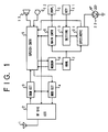
- Fig. 1 is a block diagram showing the first embodiment of the present invention, in which the present invention is applied to an automobile telephone.
- a mobile communications equipment in this embodiment comprises an antenna 1, and a radio-frequency signal circuit 2 which receives a signal sent from another equipment and transmits a signal directed toward the other equipment and which processes the radio-frequency signals.
- a demodulation circuit 3 demodulates the received signal, while a modulation circuit 4 modulates the signal to-be-transmitted.
- a speech controller 5 performs the filtering of a speech signal received or to-be-transmitted, and also performs the generation of a ringing tone or a warning sound, the control of a speech route, etc.
- a modem circuit 6 demodulates system control data inserted between speech data, into digital data, and it also modulates such digital data.
- An analyzer 7 analyzes the received system control information, and delivers the analyzed result to a main controller 8.
- the analyzer 7 serves also as analysis means for analyzing whether or not the communications of the pertinent equipment with the other equipment are possible.
- the main controller 8 controls the operation of the whole equipment functioning as an automobile telephone set.
- Display means 9 is, for example, a display unit made of liquid crystal or the like. It displays the data of a dialing input and the state of the automobile telephone set proper.
- Shown at numeral 11 is a key circuit which serves as an instruction input unit, and which accepts key inputs for the dialing, etc.
- a setting unit 10 which serves as setting means analyzes the depressions of the keys 11, and delivers a set content to the main controller 8.
- a microphone 12 and a speaker 13 constitute input/output means, herein the handset of the telephone set.
- the microphone 12 accepts an external signal, or converts the voice signal into an electric signal.
- the speaker 13 converts the signal demodulated by the demodulation circuit 3, into a voice signal which is externally given forth.
- the construction explained above is similar to the main construction of an automobile telephone set in the prior art.
- the automobile telephone set is additionally provided with a detection/notification unit 21 and an LED (light emitting diode) 22.
- the detection/notification unit 21 includes detection means for detecting the state change between the communicable state of the equipment and the incommunicable state thereof on the basis of the analyzed result of the analyzer 7, and notification means for giving notification to the user of the equipment when the state change has been detected by the detection means.
- the notification means includes at least one constituent notification means selected from among message output means for producing a voice message as the notification, sound output means for producing a notifying sound (beep) as the notification, optical indication means for producing a notifying light as the notification, and vibration means for producing vibrations as the notification.
- the case of utilizing the LED 22 for emitting the notifying light of the optical indication means is exemplified as the notification means.
- the LED 22 can be kept continuously lit or it can be flickered.
- the analyzer 7 receives the system control data which are continually sent by a base station installed on the ground.
- the signal at a specified frequency namely, in a specified radio channel
- the received signal is demodulated by the demodulation circuit 3, and the demodulated signal is delivered to the speech controller 5.
- the speech controller 5 the speech signal and the system control signal are separated by filtering.
- the system control signal is demodulated by the modem 6 into the digital data, the content of which is thereafter analyzed by the analyzer 7.
- the main controller 8 controls the operation of the whole automobile telephone set on the basis of the analyzed result of the analyzer 7. Accordingly, whether or not the telephone set lies within the service area can be decided from the analyzed result of the analyzer 7.
- the system control signal sent from the base station cannot be normally received, and hence, the output from the analyzer 7 ceases or disappears.
- the main controller 8 responsively controls the radio-frequency signal circuit 2 so as to alter the radio channel to another one and to check if a system control signal sent from another base station is receivable on the new channel.
- the main controller 8 controls the display unit 9 so as to present a display indicative of "outside the service area". Even after the display has been presented, the main controller 8 continues the receiving operation while changing the radio channel until the system control signal becomes receivable, that is, until the output of the analyzer 7 falls into the normal state. In the situation where the communicable radio channel is being searched for, the automobile telephone set is capable of neither call origination nor call termination. Therefore, even when the user depresses the keys 11, the main controller 8 operates to hinder the transmitting operation. In due course, when the system control signal has been normally received, the analyzer 7 supplies the main controller 8 with the analyzed result. The main controller 8 responsively controls the display unit 9 so as to remove the display "OUTSIDE SERVICE AREA". Thenceforth, the automobile telephone set is capable of both call origination and call termination.
- the detection/notification unit 21 and the LED 22 are added to the prior-art automobile telephone set.
- the output of the analyzer 7 is also applied to the detection/notification unit 21, which decides if the telephone set lies in the communicable area.
- the detection/notification unit 21 flickers the LED 22 or/and produces the notifying sound by controlling the speech controller 5, thereby notifying the user of the communicability.
- the user can set the operation of the detection/notification unit 21 via the setting unit 10 with the keys 11. In this embodiment, whether or not the notifying operation is to be performed can be set.
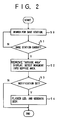
- Fig. 2 is a flow chart showing an example of the operation of this embodiment.
- the main controller 8 controls the display unit 9 so as to present the display "OUTSIDE SERVICE AREA". Thereafter, it changes the radio channel in order to search for a new base station (step 50).
- the system control signal has been received during the search operation, whether or not the base station has been caught is decided (step 51). This decision is rendered in such a way that the analyzer 7 analyzes the content of the received signal to check if the signal is the system control signal of the new base station.
- the main controller 8 changes the radio channel, and the routine returns to the step 50.
- the display "OUTSIDE SERVICE AREA" presented on the display unit 9 is removed (step 52).
- the detection means of the detection/notification unit 21 detects that the state of the telephone terminal has changed.
- the state change is from the incommunicable state into the communicable state
- how the operation of the detection/notification unit 21 is set is checked (step 53). In this embodiment, whether or not the detection/notification unit 21 is to perform the notifying operation can be set through the setting unit 10.
- the detection/notification unit 21 first checks if the notifying operation is set. The routine proceeds to a step 54 when the notifying operation is set, and it is directly ended when not. On condition that the notifying operation is set, the detection/notification unit 21 flickers the LED 22, and it also controls the speech controller 5 so as to emit the notifying sound (beep) from the speaker 13 (step 54). Owing to the above operating features operations, when the automobile telephone terminal has picked up the new base station, not only is the display "OUTSIDE SERVICE AREA" removed, but also the LED 22 is flickered while at the same time, the beep is produced from the speaker 13.
- the operator of the telephone terminal can know the usability thereof without confirming the disappearance of the display "OUTSIDE SERVICE AREA" from the display unit 9, so that the convenience of the telephone terminal is enhanced.
- this embodiment is effective to enhance driving safety.
- the notifying operation of the detection/notification unit 21 can be set using the keys 11, so that the beep can be produced only when necessary.
- FIG. 2 corresponds to the case where the user is notified of the entry from outside the service area into this service area. It is also possible to notify the user that the telephone terminal has moved out of the service area.
- Fig. 3 is a flow chart showing an operating example in the case where the user is notified of the movement out of the service area. Now, the operation of the embodiment in this case will be described with reference to Figs. 1 and 3.
- the output from the analyzer 7 ceases or disappears (step 55).
- the main controller 8 responsively controls the radio-frequency signal circuit 2 so as to alter the radio channel to another one and to check if a system control signal sent from another base station is receivable on this new channel (step 56). In a case where the system control signal has been successfully received, the main controller 8 registers the newly picked up base station and ends the processing (step 58). On the other hand, in a case where the system control signal cannot be received on any of radio channels set, the main controller 8 controls the display unit 9 so as to present the display indicative of "outside the service area" (step 57). On this occasion, the detection means of the detection/notification unit 21 detects the state change based on the movement out of the service area.
- the main controller 8 checks if the setting unit 10 is set so as to perform the notifying operation of the detection/notification unit 21 (step 53). The routine proceeds to a step 54 when the notifying operation is set, and it is directly ended when not. On condition that the notifying operation is set, the detection/notification unit 21 flickers the LED 22, and it also controls the speech controller 5 so as to emit the notifying sound (beep) from the speaker 13 (step 54). After the end of the above processing, the main controller 8 continues the receiving operation while changing the radio channel until the system control signal becomes receivable, that is, until the output of the analyzer 7 falls into the normal state.
- the convenience of the telephone terminal is enhanced more by employing both the operating examples shown in Figs. 2 and 3.
- the aspect of notification can be made different between the case of movement into the service area and the case of movement out of the same, thereby permitting the user to distinguish the movements from each other.
- the convenience can be enhanced remarkably.
- it facilitates the distinction by the user that the movement into the service area is chimed by the use of the speaker 13, whereas the movement out of the service area is buzzed.
- the flickering intervals or lighting-up method of the LED 22 may well be changed for the same purpose.
- the beep from the speaker 13 and the flickering of the LED 22 are conjointly utilized as the expedients of the notifications.
- another notifying method may well be adopted, and the notifying methods may well be selectable.
- the notification means includes three sorts of expedients; the production of the message from the voice generator 33 (replacing the production of the beep from the speaker 13 based on controlling the speech controller 5), the flickering of the LED 22, and the production of the vibrations based on the operation of the vibrator 31.
- These notifying expedients can be selected through the switching circuit 32.
- the constituent notification means can be selected and altered by the setting of the setting unit 10 from the keys 11.
- the operations of the other components are the same as in the embodiment shown in Fig. 1.
- the detection/notification unit 21 detects the state change on the basis of the change of the output of the analyzer 7. After the detection, the unit 21 performs the notifying operation through the switching circuit 32. Owing to the function of the switching circuit 32, the three sorts of constituent notification means can be selected in accordance with the setting of the setting unit 10.
- the constituent means of the notification means can be selected, so that the user can utilize the appropriate constituent means in TPO (time, place, occasion) fashion.
- TPO time, place, occasion
- the user in a case where the user does not wish for the emission of the sound in the vehicle, he/she can select the notifying expedient based on the vibrations or flickering.
- the user in a case where the user is having difficult noticing the state change with only the flickering of the LED 22, he/she can select the notifying expedient based on the vocal message, for example, "The telephone set is usable.”, "The telephone set has moved out of the service area.” or "The service area has changed.”. Therefore, this embodiment has the effect that the user can select the desired setting.
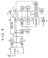
- Fig. 5 is a block diagram showing the third embodiment of the present invention. The point of difference of this embodiment from the first embodiment shown in Fig. 1 is that the conditions for performing the notifying operation of the detection/notification unit 21 are made selectable.
- timekeeping means 23 for measuring an elapsed time period is connected to the detection/notification unit 21, making it possible to alter the timing of performance of the notifying operation.
- the radio-frequency signal circuit 2 includes electric field strength detection means for detecting the electric field strength of the received signal.
- the detection means of the circuit 2 supplies the detection/notification unit 21 with information on the electric field strength of the received signal.
- the performance of the notifying operation can be controlled depending upon the strength of the electric field of the received signal.
- the items of the conditions for the performance of the notifying operation which can be set in the embodiment shown in Fig. 5 are listed in Table 1 below, along with the set contents of the condition items. All the conditions for the performance and the contents can be set by operating the setting unit 10 from the keys 11 which serve as the instruction input means. The user can alter the setting as required.
- TABLE 1 Item of Condition Set Contents 1. Number of Times of Performance Setting #1: Notifying operation is not performed. Setting #2: Performed at first time only. Setting #3: Performed at all times. 2. Electric field strength Setting #1: Performed irrespective of field strength. Setting #2: Performed at above predetermined level. 3. Timing of Performance Setting #1: Performed immediately. Setting #2: Performed after lapse of predetermined time.
- the condition item #1 serves to set the number of times of performance of the notifying operation.
- the nonperformance of the notifying operation can also be selecting by the setting #1 of the set contents.
- the setting #2 is especially provided as one feature of this embodiment in consideration of the convenience of the communications equipment to the user, and it functions to perform the notifying operation only one time after the user's setting.
- the setting #2 causes the notification means to give the notification at the first state change only.
- the number of times of performance in the setting #2 may well be optionally set to 2 or more.
- the setting #3 makes it possible to give the notification at every state change.
- the number of times of performance as the condition item #1 can be stored and controlled within the detection/notification unit 21. It is therefore to be understood that the setting of this condition is also applicable to the embodiments shown in Fig. 1 and Fig. 4.
- the condition item #2 of the electric field strength and the condition item #3 of the performance timing are provided in order to verify that the communicable state of the telephone terminal is stable.
- received electric waves are of low field strength, and they often disappear soon after the telephone terminal has fallen into the communicable state.
- the state thereof is frequently changed between the communicable state and the incommunicable state, and the notifying operation might be frequently performed.
- the condition items 2 and 3 are very effective.
- the setting #2 of the condition item #2 signifies that the notifying operation is performed when the electric field strength measured by the detection means of the radio-frequency signal circuit 2 has exceeded a certain predetermined level.
- the conditioned performance can avoid the unstable operation of the telephone terminal attributed to the weak electric field near the border of the service area.
- the notifying operation is performed when the telephone terminal has been checked by the timekeeper 23 as lying within the service area continually for the predetermined time period, and it can be verified that the telephone terminal has fully entered the service area.
- the notifying operation is performed when the telephone terminal has been checked by the timekeeper 23 as lying within the service area continually for the predetermined time period, and it can be verified that the telephone terminal has fully entered the service area.
- the propagation of electric waves changes complexly, and hence, the electric field strength thereof can change suddenly in a short time.
- Fig. 6 is a flow chart showing an example of the operation in the case where the condition items #2 and #3 of the condition items listed in Table 1 are fixedly set beforehand.
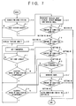
- Fig. 7 is a flow chart showing another example of the operation in the case where the user can set all the condition items listed in Table 1.
- the main controller 8 controls the display unit 9 so as to present the display "OUTSIDE SERVICE AREA". Thereafter, it changes the radio channel in order to search for a new base station (step 50).
- the content thereof is analyzed by the analyzer 7 to decide whether or not the signal is the system control signal of a new base station (step 51).
- the main controller 8 changes the radio channel, and the routine returns to the step 50.
- the display "OUTSIDE SERVICE AREA" presented on the display unit 9 is removed (step 52).
- the analyzed result of the analyzer 7 is also supplied to the detection/notification unit 21, in which the pick up of the base station is detected.
- the detection/notification unit 21 checks the setting of the condition item #1 (step 53'). That is, at the step 53', the condition item #1 indicated in Table 1 is checked to decide how the operation of the detection/notification unit 21 is set.
- the routine proceeds to a step 60, and when the condition item #1 is set at the setting #1, the routine is directly ended.
- the timekeeper 23 is set or is started timekeeping (step 60). Thereafter, if the electric waves of the base station can be stably received for the preset time period is checked at steps 61 and 62. When the electric waves of the base station have disappeared (step 62), it is decided that the service area has been missed, and the display "OUTSIDE SERVICE AREA" is presented (step 68). Thereafter, the routine returns to the step 50.
- the detection/notification unit 21 has detected the lapse of the preset time period from the output signal of the timekeeper 23, the step 61 is followed by a step 63.
- the detection/notification unit 21 checks the received electric field strength on the basis of the electric field strength information supplied from the radio-frequency signal circuit 2.
- step 63 and a step 64 are iterated. Meantime, when the electric waves of the base station have disappeared (step 64), resulting in the decision that the service area has been missed, the display "OUTSIDE SERVICE AREA" is presented (step 68), and the routine returns to the step 50.
- step 63 is followed by a step 54'.
- the detection/notification unit 21 flickers the LED 22, and it controls the speech controller 5 so as to emit the beep from the speaker 13.
- the condition item #1 indicated in Table 1 is checked (step 66). When the set content of the condition item #1 is the setting #2, the notifying operation ought to be performed only once. Therefore, the set content is altered to the setting #1 (step 67) so as not to perform the notifying operation again.
- the operation shown in Fig. 7 differs from the above operation shown in Fig. 6 in that the user can also set the condition items #2 and #3 freely.
- the main controller 8 controls the display unit 9 so as to present the display "OUTSIDE SERVICE AREA". Thereafter, it changes the radio channel in order to search for a new base station (step 50).
- the system control signal has been received during the search operation, the content thereof is analyzed by the analyzer 7 to decide whether or not the signal is the system control signal of a new base station (step 51).
- the main controller 8 changes the radio channel, and the routine returns to the step 50.
- the display "OUTSIDE SERVICE AREA" presented on the display unit 9 is removed (step 52).
- the analyzed result of the analyzer 7 is also supplied to the detection/notification unit 21, which detects the picking up of the base station or the state change.
- the detection/notification unit 21 checks the condition item #1 in Table 1 (step 53') as to how the notifying operation thereof is set.
- the routine proceeds to a step 70, and when the condition item #1 is set at the setting #1, the routine is directly ended.
- the condition item #3 is checked (step 70).
- the step 70 is directly followed by a step 71 subject to the setting #1 of the condition item #3, and it is followed by steps 60 et seq. subject to the setting #2 of the condition item #3.
- the timekeeper 23 is operated to check if the electric waves of the base station can be stably received for the preset time (steps 60 ⁇ 62).
- the processing of these steps 60 ⁇ 62 is the same as in the example illustrated in Fig. 6.
- the condition item #2 is checked.
- the step 71 is directly followed by a step 54' subject to the setting #1 of the condition item #2, and it is followed by steps 63 et seq. subject to the setting #2.
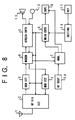
- Fig. 8 is a block diagram showing an example of a digital mobile communications terminal which transmits all speech and data in terms of digital signals.
- the communications equipment in this embodiment comprises an antenna 1, and a radio-frequency signal circuit 2 which receives a signal sent from another equipment and transmits a signal directed toward the other equipment and which processes the radio-frequency signals.
- a demodulation circuit 3 detects the received signal synchronously, while a modulation circuit 4 modulates the signal to-be-transmitted orthogonally.
- a modem circuit 6 demodulates the synchronously-detected signal into digital data. The modem circuit 6 also functions to correct errors and to convert digital data into the orthogonal signal to-be-transmitted.
- a speech controller 5 quantizes the speech signal received or to-be-transmitted, and also performs the processing of data compression/expansion, the generation of a ringing tone or a warning sound, the control of a speech route, etc.
- An analyzer 7 serves as analysis means for analyzing whether or not the communications of the pertinent equipment with the other equipment are possible.
- a main controller 8 controls the operation of the whole equipment functioning as an automobile telephone set.
- Display means 9 is, for example, a display unit made of liquid crystal or the like. It displays the data of a dialing input and the state of the automobile telephone set proper.
- Shown at numeral 11 is a key circuit which serves as an instruction input unit, and which accepts key inputs for the dialing, etc.
- Network #1 is a communications network or circuit through which the pertinent equipment communicates with a preset host station as in a cordless telephone system
- Network #2 is a personal network or circuit which is individually provided for private communications
- Network #3 is a public radio network which has been individually subscribed to with a network offerer
- Network #4 is another public radio network which is usable
- Network #5 is a special network such as a satellite circuit which is usable through a satellite or an emergency circuit which is opened in case of emergency. Whether or not any of the networks is usable, is decided in such a way that the analyzer 7 analyzes the output system control data of the modem 6 while comparing it with the registered contents of the network registration unit 24.
- Network #1 Base circuit Connected with specified host station.
- Network #2 Personal circuit Individual network such as private radio system
- Network #3 Subscriber network Public network subscribed to.
- Network #4 Roaming network Another public network.
- Network #5 Special network Satellite link, emergency circuit, or the like.
- a specified frequency (“radio channel")
- the received signal is subjected to the synchronous detection by the demodulation circuit 3, and the detected signal is supplied to the modem 6.
- the modem 6 demodulates the input signal into the digital data, the speech data of which is delivered to the speech controller 5 and the system control signal of which is delivered to the analyzer 7 and has its content analyzed.
- the system control data is continually sent from the host station or a transponder, and it contains peculiar recognition data or classification code data so as to distinguish the sort of the corresponding network.
- the analyzer 7 decides whether or not the network is usable, by analyzing the system control data in comparison with the registered contents of the network registration unit 24, and it delivers the analyzed result to the main controller 8 as well as the display unit 9.
- the main controller 8 controls the operation of the whole automobile telephone set on the basis of the analyzed result of the analyzer 7.
- the speech data is subjected to the data expansion and then converted into an analog signal by the speech controller 5, and the analog signal is converted into a voice signal by the speaker 13.
- the analyzed result of the analyzer 7 is also supplied to the display unit 9 so as to display the sort of the usable network.
- Fig. 12 shows an example of the display of the display unit 9.
- the sorts of networks as listed in Table 2 are indicated as shown in the lower part of Fig. 12, and the lamps of the usable networks are lit up or flickered.
- the electric field strength of the received signal and the display "OUTSIDE SERVICE AREA" may well be displayed as shown in the upper part of Fig. 12.
- the embodiment shown in Fig. 8 may well be provided with detection/notification means including detection means and notification means.
- the analyzer 7 decides the sort of the communicable network from the signal received by the radio-frequency signal circuit 2.
- the detection means detects the change of the sort of the communicable network from the analyzed result of the analyzer 7.
- the notification means notifies the user of the telephone set that the sort of the network has changed, in response to the detection of the detection means.
- the analyzer 7 analyzes the communicable networks from the signals received by the radio-frequency signal circuit 2, with reference to the network registration unit 24.
- the detection means detects the state changes of the respective networks between the communicable and incommunicable states thereof, on the basis of the analyzed results of the analyzer 7.
- the notification means notifies the user of the state changes of the respective networks detected by the detection means.
- the detection/notification unit 21 detects if the network selected by the priority setting unit 25 has fallen into a communicable or incommunicable state, from the change of the analyzed result of the analyzer 7, and it notifies the user of the state change.
- the detection/notification unit 21 includes detection means for detecting the change between the communicable and incommunicable states of the network selected by the priority setting unit 25, on the basis of the analyzed result of the analyzer 7, and notification means for notifying the user of the state change detected by the detection means.
- the voice generator 33 produces any necessary preset messages in accordance with the output signal of the detection/notification unit 21. This voice generator 33 forms part of message output means, and the vocal message is emitted by the speaker 13.
- the operations of the other components are the same as in the embodiment shown in Fig. 8.
- the embodiment shown in Fig. 9 operates as described below.
- the detection/notification unit 21 can decide whether or not the network registered in the network registration unit 24 lies within a service area, from the analyzed result of the analyzer 7.
- the system control signal sent from the host station or the base station cannot be normally received, and hence, the output from the analyzer 7 ceases or disappears.
- the peculiar recognition data or classification code data for discriminating the sort of the network as contained in the system control data changes, so that the detection/notification unit 21 can know the change of the network from the change of the output of the analyzer 7.
- the main controller 8 controls the radio-frequency signal circuit 2 so as to alter the radio channel to another one and to check if a system control signal sent from another base station is receivable.
- the main controller 8 controls the display unit 9 so as to present the display indicative of "outside the service area". Even after the display has been presented, the main controller 8 continues the receiving operation while changing the radio channel until the system control signal becomes receivable, that is, until the output of the analyzer 7 falls into the normal state. In the situation where the communicable radio channel is being searched for, the digital automobile telephone set is capable of neither call origination nor call termination.
- the main controller 8 operates to hinder the transmitting operation.
- the analyzer 7 supplies the main controller 8 with the analyzed result.
- the main controller 8 responsively controls the display unit 9 so as to remove the display "OUTSIDE SERVICE AREA". Thenceforth, the digital automobile telephone set is capable of both call origination and call termination.
- the output of the analyzer 7 and that of the priority setting unit 25 are supplied to the detection/notification controller 21, whereby the detection/notification controller 21 decides whether or not the network selected by the priority setting unit 25 is usable.
- the detection/notification controller 21 can flicker the LED 22 or/and emit the notifying message through the control of the voice generator 33, to notify the user that the digital mobile communications equipment has become communicable or incommunicable or that the usable network has changed.
- the user can set the operation of the detection/notification unit 21 via the setting unit 10 with the keys 11. In this embodiment, whether or not the notifying operation is to be performed can be set.
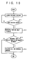
- the main controller 8 controls the display unit 9 so as to present the display "OUTSIDE SERVICE AREA". Thereafter, it changes the radio channel in order to search for a new base station (step 80).
- the content of the received signal is analyzed by the analyzer 7, to decide if the signal is the system control signal of the new base station (step 81).
- the main controller 8 changes the radio channel, and the routine returns to the step 80.
- the display "OUTSIDE SERVICE AREA" presented on the display unit 9 is removed (step 82).
- the operations thus far explained are the same as in the prior-art automobile telephone terminal.
- the detection/notification controller 21 is supplied with the analyzed result of the analyzer 7 and the output of the priority setting unit 25, and it decides whether or not the network selected by the priority setting unit 25 has become usable (step 83).
- the detection/notification controller 21 flickers the LED 22, and it also controls the voice generator 33 so as to emit the notifying message from the speaker 13 (step 84), thereby notifying the user of the state change into the communicable state.
- the detection/notification controller 21 may include vibration means so as to give the notification in terms of vibrations. It may well include sound output means so as to give the notification in terms of a notifying sound (beep).
- this embodiment may well be so contrived that the constituent means of the notification means to be used for the notification can be selectively set.
- the operating example shown in Fig. 10 corresponds to the case where the user is notified of the entry from outside the service area into this service area.
- the user can also be notified of the movement of the telephone terminal out of the service area as in the embodiment shown in Fig. 3, with ease in such a way that the detection/notification unit 21 detects the outward movement on the basis of the output of the analyzer 7.
- the convenience can be more enhanced in such a way that the aspect of notification is made different between at the case of movement into the service area and the case of movement out of the same, thereby permitting the user to distinguish the movements from each other.
- it facilitates the distinction by the user that the movement into the service area is notified by emitting a message "The telephone terminal is usable.” from the speaker 13, whereas the movement out of the service area is notified by emitting a message "The service area has been left".
- the flickering intervals or lighting-up method of the LED 22 may well be changed for the same purpose.
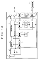
- Fig. 11 is a block diagram showing an embodiment of a digital mobile communications terminal which automatically performs a dialing operation at the time of entry into the service area.
- the embodiment shown in Fig. 11 is additionally provided with a dialing starter 26, a checker 27, a memory 28 and a dialing confirmation unit 29.
- the other components are the same as in Fig. 9.
- the memory 28 stores therein the telephone No. or recognition No. of an opposite party to-be-dialed.
- the embodiment shown in Fig. 11 operates as described below.
- the system control signal becomes receivable, and the analyzer 7 delivers the analyzed result to the main controller 8 as well as the detection/notification unit 21.
- the detection/notification unit 21 checks the usability of one of the networks registered in the network registration unit 24 as selected by the priority setting unit 25.
- the unit 21 decides the selected network to be usable as the result of the check, it notifies the user of the communicability by flickering the LED 22 or/and emitting the notifying message from the speaker 13 through the control of the voice generator 33.
- the operations thus far explained are the same as in the embodiment shown in Fig. 9.
- the detection/notification unit 21 Upon detecting that the network selected by the priority setting unit 25 has become usable, the detection/notification unit 21 delivers the detected result to the checker 27.
- the checker 27 responsively checks the conditions set in the setting unit 10.
- the conditions to be set in the setting unit 10 are whether or not a hands-free function is to be implemented, whether the user's reply is to be the key input or the vocal answer, and so forth.
- the checker 27 starts the dialing confirmation means 29 subject to the set conditions of the setting unit 10 that the autodialing operation is to be performed and that the dialing operation is to be confirmed by the user.
- the dialing confirmation means 29 responsively emits the message, for example, "May Vietnamese be called?", thereby requesting the user to confirm the dialing.
- the dialing confirmation means 29 delivers the confirmed result to the checker 27.
- the checker 27 supplies a start signal to the dialing starter 26, which works on the main controller 8 so as to start the dialing operation.
- the desired opposite party is automatically dialed at the entry of the telephone terminal into the service area by merely setting the telephone No. or recognition No. of the opposite party in the memory 28 and the condition of the performance of the autodialing operation in the setting unit 10 beforehand during the movement of the telephone terminal in an incommunicable region. Therefore, this embodiment is effective to enhance the convenience of the telephone terminal. Moreover, since the confirmation of the dialing operation can be set, the performance of any unfavorable dialing can be prevented in, for example, a case or a place where the user cannot call. Especially when the hands-free function is conjointly utilized, the confirming operation and the keying operation can be dispensed with during the driving of the automobile in which the telephone terminal is installed. Therefore, this embodiment is effective to enhance driving safety.
- each foregoing embodiment is further provided with a memory which stores the identification information therein, a starter which starts the commencement of the communications in accordance with the identification information stored in the memory, and a checker which commands the starter to start the communications commencement in response to the state change from the incommunicable state into the communicable state as detected by the detection means, on condition that the communications commencement instruction has been accepted by the key circuit 11 in the incommunicable state.
- Fig. 13 is a block diagram showing an example in which the peripheral equipment is connected to the mobile communications terminal.
- numeral 100 indicates the mobile terminal.
- the peripheral equipment 101 connected to the mobile terminal 100 can give notification to the user.
- Examples of the peripheral equipment are a navigation equipment, a car TV set, a portable TV set, etc. each of which has a display function, and the car stereo, a headphone stereo, a tape recorder, a hearing aid, etc. each of which has a sounding function.
- the mobile terminal 100 is constructed substantially similarly to the embodiment shown in Fig. 1, and identical numerals are respectively assigned to the blocks of the terminal 100 having the same operations as in Fig. 1. This embodiment shown in Fig. 13 differs from the embodiment shown in Fig.
- the output unit 34 receives at least one piece of information among control information for controlling the peripheral equipment 101 as delivered from the main controller 8, electric field strength information delivered from the radio-frequency signal circuit 2, and notification information for notifying the user of the state change between the communicable and incommunicable states as delivered from the detection/notification unit 21.
- the output unit 34 turns the information into a signal s1 which is compatible with the peripheral equipment 101, and transfers the signal s1 to the peripheral equipment 101.
- FIG. 14 An example of construction of the peripheral equipment 101 is shown in Fig. 14.
- a data input unit 38 serving as input means receives the signal s1 transferred from the output unit 34 of the mobile terminal 100.
- a data analyzer 37 serving as analysis means analyzes the transferred signal, and extracts the information.
- a controller 36 controls the whole peripheral equipment 101.
- a peripheral unit 41 performs the original operation of the peripheral equipment 101.
- a display circuit 39 serves to present a display on a display unit 43, and a beep generator 40 generates a beep through a speaker 42.
- As the display circuit 39 and the display unit 43 ones with which the peripheral equipment 101 is furnished are respectively utilized. In a case where the peripheral equipment 101 is not furnished a display circuit or unit, they may well be omitted from the illustrated construction.
- the notifying operation can be previously determined in accordance with the sort of pertinent peripheral equipment 101.
- a peripheral equipment includes, at least, input means for receiving the notifying information from the output means of the associated mobile communications equipment, analysis means for analyzing the content of the notifying information accepted by the input means, and notification means for performing a predetermined notifying operation on the basis of the analyzed result of the analysis means.
- the analyzer 7 analyzes the signal received by the radio-frequency signal circuit 2 in the state in which the mobile terminal 100 in Fig. 13 is incommunicable, that is, in which the base station is not picked up.
- the detection means of the detection/notification means 21 detects the state change of the mobile terminal 100 on the basis of the analyzed result of the analyzer 7. Thereafter, the notification means of the detection/notification unit 21 transfers the notifying information as the signal s1 to the peripheral equipment 101 through the output unit 34 in order to notify the state change from the incommunicable state into the communicable state.
- the notifying information is delivered to the data analyzer 37 of the peripheral equipment 101 through the data input unit 38 thereof, and is recognized as such in this data analyzer. Then, the data analyzer 37 informs the controller 36 that the notifying information has been transferred to the peripheral equipment 101.
- the controller 36 having received the notifying information controls the display circuit 39 so as to flicker the screen of the display unit 43 or to display the message thereon.
- the controller 36 controls the beep generator 40 so as to emit the beep from the speaker 42.
- the peripheral equipment 101 can notify the user that the mobile terminal 100 has become communicable.
- changes of the display and the generation of the beep have been exemplified here, it is a matter of course that a function peculiar to such a peripheral equipment may well be utilized. Any of multifarious notifying methods can be obtained in such a manner that a vocal message is output by a voice producing function, that music is played by a melody producing function, and that vibrations are developed by a vibration producing function.
- Fig. 15 is a block diagram showing an example in which the peripheral equipment having the communicating function is connected to the mobile communications terminal equipment.
- numeral 100 indicates the mobile terminal.
- the peripheral equipment 102 connected to the mobile terminal 100 is the FAX equipment or the like having the communicating function.
- the mobile terminal 100 is constructed substantially similarly to the embodiment shown in Fig. 13, and identical numerals are respectively assigned to the blocks of the terminal 100 having the same operations as in Fig. 13. The points of difference of this embodiment shown in Fig. 15 from the foregoing embodiment shown in Fig.
- the input unit 35 functions to supply the setting unit 10 with the signal s2 transferred from the peripheral equipment 102, likewise to the operation of the key circuit 11.
- the communications signals s3 are the output/input signals of transmission/reception information in the peripheral equipment 102.
- the output signal of the transmission information is sent to the opposite terminal of the communications over the radio channel via the speech controller 5, modulation circuit 4, radio-frequency signal circuit 2 and antenna 1. Contrariwise, the input signal of the reception information is sent to the peripheral equipment 102 via the antenna 1, radio-frequency signal circuit 2, demodulation circuit 3 and speech controller 5.
- the output unit 34 receives control information for controlling the peripheral equipment 102 as delivered from the main controller 8, electric field strength information delivered from the radio-frequency signal circuit 2, and notification information for notifying the user of the state change between the communicable and incommunicable states as delivered from the detection/notification unit 21.
- the output unit 34 turns the information into a signal s1, and transfers the signal s1 to the peripheral equipment 102.
- a control data output unit 48 transfers control data (the signal s2) for controlling the mobile terminal 100 from the peripheral equipment 102.
- a peripheral equipment is further provided with an instruction input unit which accepts the identification information of the other mobile communications equipment, a memory which stores therein the identification information accepted by the instruction input unit, a start command unit which commands the associated mobile communications equipment to start the commencement of the communications in accordance with the identification information stored in the memory, and a checker which is endowed with an autodialing mode that causes the start command unit to operate in response to the state change from the incommunicable state into the communicable state as detected on the basis of the output of the analysis means, on condition that the communications commencement instruction has been accepted by the instruction input unit in the incommunicable state.
- An ordinary interface (for example, "X. 25" in the case of packet communications) is utilized as the interface between the mobile terminal 100 and the peripheral equipment 102 such as FAX equipment or data communications terminal.
- the communications are done in such a way that specified signal patterns to be transmitted and received are stipulated in the signals s1 and s2 beforehand.
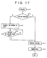
- Fig. 17 is a flow chart for explaining the operation of this embodiment.
- the user performs a dialing operation with the peripheral equipment 102 (step 85).
- the controller 46 responsively controls the control data output unit 48 so as to supply the mobile terminal 100 with the control signal s2 for ascertaining if the communications are possible.
- the main controller 8 On the side of the mobile terminal 100, the main controller 8 having received the control signal s2 through the input unit 35 as well as the setting unit 10 transfers the signal s1 indicating if the communications are possible, from the output unit 34 to the peripheral equipment 102.
- the signal s1 is received by the data input unit 38, the content of this signal is analyzed by the data analyzer 37, and the analyzed result is received by the controller 46.
- the controller 46 decides that the dialing is possible (step 86). In this case, the controller 46 transfers dialing information to the mobile terminal 100 through the control data output unit 48 at a step 87. Thus, the dialing operation is executed.
- the peripheral equipment 102 After the peripheral equipment 102 has been connected with the other equipment over the radio channel, it transmits and receives the signals s3 through the modem 44, thereby to communicate with the opposite equipment (step 88).
- the routine proceeds to a step 89.
- the controller 46 controls the display circuit 39 so as to display "ON STANDBY TO DIAL" on the display unit 43 at the step 89, thereby to inform the user that the dialing is impossible. Thenceforth, it is waited at a step 90 there is a wait for the dialing start unit 45 to become operable.
- the analyzer 7 analyzes the signal received by the radio-frequency signal circuit 2 in the incommunicable state in which the base station is not picked up.
- the detection means of the detection/notification means 21 detects the state change of the mobile terminal 100 on the basis of the analyzed result of the analyzer 7. Thereafter, the notification means of the detection/notification unit 21 transfers the notifying information (the signal s1) to the peripheral equipment 102 through the output unit 34 in order to notify the state change from the incommunicable state into the communicable state.
- the notifying information is delivered to the data analyzer 37 of the peripheral equipment 102 through the data input unit 38 thereof, and is recognized as such in this data analyzer. Then, the data analyzer 37 informs the dialing start unit 45 of the recognition of the notifying information.
- the dialing start unit 45 responsively informs the controller 46 that the notifying information has been transferred to the peripheral equipment 102, and it also starts the dialing operation. Then, the routine proceeds to the step 87, at which the controller 46 transfers dialing information to the mobile terminal 100 through the control data output unit 48. Thus, the dialing operation is executed. After the peripheral equipment 102 has been connected with the other equipment over the radio channel, it communicates with the opposite equipment through the modem 44 (step 88).
- this embodiment brings forth the effect that the user is freed from repeatedly having to confirm the state of the mobile terminal 100.
- a notifying sound (beep) or the like may well be employed for informing the user that the dialing operation has been started.
- any expedient may be employed for the connection between the mobile terminal 100 and the peripheral equipment 102. Examples of the expedient are optical transmission, radio transmission and acoustic transmission.
- the state change of a mobile communications equipment based on the movement thereof such as the state change from outside a service area into the same
- the user of the equipment can know the communicability thereof without expressly checking the display of a display unit, so that the convenience of the equipment is enhanced.
- the user is driving an automobile, he/she can confirm his/her entry into the service area without any hindrance to his/her driving operation, so that the driving safety is enhanced.
Abstract
Description
- The present invention relates to mobile communications equipment. More particularly, it relates to mobile communications equipment which is well suited to a case where a communications terminal moves out of a service area or to a case where it is connectible to a plurality of sorts of network.
- In mobile communications, a radio channel for communication is established between a mobile communications terminal which moves on the ground, on the sea or in the sky and a base station or relay station which is fixed, e. g., on the ground or a satellite which is revolving round the earth. Whenever the base station or the like is located within a range in which a radio signal is reachable, the mobile communications terminal can be connected with the channel for both call origination and call termination. In a case where the mobile communications terminal is moving within such a service area, the user thereof need not especially worry about being able to talk. Since, however, base stations are not installed in all areas, the mobile communications terminal might move out of the service area. When the mobile terminal has moved out of the service area in this manner, a display is commonly presented on a display unit or the like to indicate that the mobile terminal currently lies in an area where communication is impossible.
- With the conventional mobile communications terminal as stated above, unless the user looks at the display, he/she cannot judge whether or not the terminal is currently in the service area. In a case where the user wants to communicate while walking or while moving aboard an automobile or streetcar by way of example, he/she first checks the display of the mobile communications terminal. When the display indicates "outside the service area", the user abandons the desired communication. Thereafter, he/she needs to look at the display unit again and again in order to check if the terminal has entered the service area in which communication is possible. This is rather troublesome for the user. Especially when driving the automobile, the operation of checking the display can hamper the driving movement and is a serious hazard to safety.
- Besides, in the case of a personal telephone set whose communicable range is as narrow as 10 [meters] ∼ several hundred [meters], it is quite natural that the user will pass the service area without noticing his/her entry even when he/she is walking.
- Techniques intended to solve the above drawbacks are disclosed in the official gazettes of Japanese Patent Applications Laid-open No. 318326/1989, No. 250727/1992, No. 314442/1989 and No. 207724/1992. With each of the techniques stated in the official gazettes of Japanese Patent Applications Laid-open No. 318326/1989 and No. 314442/1989, the first audible sound is generated when it is decided that a mobile communications equipment is lying inside the service area of a base station on the basis of a signal transmitted from the base station, and the second audible sound is generated when it is decided that the equipment is lying outside the service area. Thus, the user of the mobile communications equipment can be reliably informed as to whether or not the equipment lies within the service area. In addition, the technique stated in the official gazette of Japanese Patent Application Laid-open No. 250727/1992 consists in comprising a reception means for detecting a communicable state through a base station, and transfer means adapted to turn "on" in accordance with a communicability signal detected by the reception means, for transferring the communicable state in terms of notification expedients such as a sound, a display and vibrations. It is claimed that, in this way, the presence of the base station can be automatically made known through the use of the five senses in a car or on the street. Further, with the technique stated in the official gazette of Japanese Patent Application Laid-open No. 207724/1992, the reception levels of a plurality of sorts of signals from a transmitter are detected for deciding the quality of a reception state, the duration for which the reception state is decided to be no good is compared with a preset time period, and an output signal is produced when the duration has exceeded the preset time period.
- With any of the prior-art techniques, the user is notified that the mobile communications equipment has fallen into the communicable state. In this regard, even when not necessary, the notification is given whenever the communicable state has been established. That is, even when the user does not want to originate a call with the mobile communications equipment, he/she is notified. Accordingly, in the case where the notifying sound (beep) is used by way of example, it is useless information and is noisy.
- Furthermore, increase in network offerers is expected owing to the progress of communications networks in the future. In this case, service contents, charges for communications, etc. might become different depending upon the offerers of network, and users will select the sorts of the networks. Nevertheless, the prior art has not provided any convenient means for selecting one of the networks and for deciding whether or not the selected network is communicable.
- The present invention has been made in order to solve the problems explained above, and has for its object to provide a mobile communications equipment which can detect the change of a state based on the movement thereof, such as the change from outside a service area into the service area, and which permits the user thereof to designate whether or not he/she is to be notified of the state change.
- In the present invention, a mobile communications equipment for communicating with another equipment through a base station can comprise a radio-frequency signal circuit which receives a signal sent from the base station, and which transmits a signal directed back toward the base station; a demodulation circuit which demodulates the signal received by the radio-frequency signal circuit; input/output means for delivering the signal demodulated by the demodulation circuit, to a mobile communications equipment user, and for accepting an input signal to-be-transmitted from the user; a modulation circuit which modulates the signal accepted by the input/output means, and which delivers the modulated signal to the radio-frequency signal circuit; analysis means for analyzing whether or not the communications are possible, on the basis of the received signal of the radio-frequency signal circuit sent from the base station; detection means for detecting a change between a state in which the equipment is communicable and a state in which it is incommunicable, in accordance with an output of the analysis means; notification means for notifying the user of the state change when the state change has been detected by the detection means; an instruction input unit which accepts an instruction as to whether or not the notification is to be given by the notification means in response to the state change detection of the detection means; and control means for controlling the notification means so as to inhibit the notification in a case where the instruction accepted by the instruction input unit indicates that notification is not to be given.
- It is allowed that the notification means includes at least two constituent means selected from the group consisting of message output means for producing a voice message as the notification; sound output means for producing a notifying sound as the notification; optical indication means for producing a notifying light as the notification; and vibration means for producing vibrations as the notification. In this case, the control means can select different constituent means of the notification means for the detected state change from the incommunicable state into the communicable state to that used for the change from the communicable state into the incommunicable state.
- The instruction input unit can further accept an instruction for selecting which of the at least two constituent means of the notification means is to be used for the notification; and the control means can select any of the constituent means of the notification means in accordance with the selection instruction accepted by the instruction input unit. The message output means, the sound output means, the optical indication means, and the vibration means can produce at least two sorts of voice messages, at least two sorts of notifying sounds, at least two sorts of notifying lights, and at least two sorts of vibrations, respectively; the instruction input unit can further accept instructions for selecting which of the at least two constituent means of the notification means and which of the sorts of the outputs to-be-produced are to be used for the notification; and the control means can select any of the constituent means of the notification means and any of the sorts of the outputs in accordance with the selection instructions accepted by the instruction input unit or the control means can select the different sorts of the outputs to-be-produced of the constituent means of the notification means between at the detected state change of the detection means from the incommunicable state into the communicable state and at the change thereof from the communicable state into the incommunicable state.
- It is possible that, when the notification of the notification means is to be given, the instruction input unit further accepts an instruction for selecting either of giving the notification in response to every state change and giving the notification in response to only the first state change after the selection instruction; and that the control means controls the notification means in accordance with the selection instruction accepted by the instruction input unit.
- Further, the mobile communications equipment can further comprise timekeeping means for detecting the fact that no state change has taken place for a predetermined time period since the last state change; the control means deciding settlement of the last state change in accordance with the detection of the timekeeping means and then controlling the notification means so as to give notification. In this case, it is possible that the instruction input unit can further accept an instruction for selecting as a condition for giving the notification, either of the state change detection of the detection means and the detected fact of the timekeeping means; and that the control means controls the notification means in accordance with the selection instruction accepted by the instruction input unit.
- In addition, the mobile communications equipment can further comprise electric field strength detection means for detecting a received electric field strength of the signal received by the radio-frequency signal circuit; the control means deciding settlement of the communicable state and controlling the notification means so as to give the notification in a case where the change into the communicable state as based on the analysis of the analysis means has been detected by the detection means and where the detected electric field strength of the electric field strength detection means has reached a predetermined electric field strength. In this case, it is possible that the instruction input unit can further accept an instruction for selecting either of the specified situation and the state change detection of the detection means as a condition for giving the notification; and that the control means controls the notification means in accordance with the selection instruction accepted by the instruction input unit.
- The detection means is allowed to detect only the state change from the incommunicable state into the communicable state as based on the analysis of the analysis means. Alternatively, the detection means can detect both the state change from the incommunicable state into the communicable state as based on the analysis of the analysis means and the state change from the communicable state into said incommunicable state.
- Besides, the instruction input unit can accept identification information of the other equipment, and the mobile communications equipment can further comprise a memory which stores therein the identification information accepted by the instruction input unit; a starter which starts commencement of the communications in accordance with the stored identification information of the memory; and a checker which is furnished with an autodialing mode for commanding the starter to start the communications commencement in response to the change from the incommunicable state into the communicable state as detected by the detection means, in a case where an instruction for the communications commencement has been accepted in the incommunicable state by the instruction input unit.
- In addition, the checker may well include means for selectively enabling the autodialing mode.
- It is also possible that the notification means is furnished with at least two sorts of output aspects; the instruction input unit further accepts an instruction for selecting which of the output aspects is to be used for the notification; and the control means selects any of the output aspects in accordance with the selection instruction accepted by the instruction input unit, or the control means selects the different output aspects between at the detected state change of the detection means from the incommunicable state into the communicable state and at the change thereof from the communicable state into the incommunicable state.
- Moreover, in the presence of a plurality of sorts of network, it is possible that the mobile communications equipment further comprises network registration means for registering available sorts of network; that the analysis means further decides that any of the sorts of network are communicable on the basis of the signal received by the radio-frequency signal circuit; that the detection means detects the state change of the decided sort of communicable network on the basis of the analyzed result of the analysis means; and that the notification means gives notification when the state change of the decided sort of communicable network has been detected by the detection means. In this case, the equipment is also allowed to further comprise network priority setting means for setting priority levels for the sorts of network, and for selecting any of the networks in accordance with the set priority levels. Besides, the notification means can be furnished with at least two sorts of output aspects; and the control means stipulates the different output aspects for the respective sorts of the networks beforehand, and selects any of the output aspects corresponding to the sort of the network having undergone the state change. The notification means includes at least two constituent means selected from the group consisting of message output means for producing a voice message as the notification; sound output means for producing a notifying sound as the notification; optical indication means for producing a notifying light as the notification; and vibration means for producing vibrations as the notification; and the control means stipulates the different constituent means of the notification means for the respective sorts of the networks beforehand, and selects any of the constituent means corresponding to the sort of the network having undergone the state change. Further, when each of the multiple notification means have at least more than two sorts of constituent means, the control means stipulates the sorts of the outputs to-be-produced of the constituent means of the notification means for the respective sorts of the networks beforehand, and selects any of the sorts of the outputs of the constituent means corresponding to the sort of network having undergone the state change.
- As an alternative aspect of performance, the mobile communications equipment further comprises network registration means for registering available sorts of network; the analysis means further analyzing the networks being communicable on the basis of the signal received by the radio-frequency signal circuit, with reference to the network registration means; the detection means detecting the state change of each of the communicable networks on the basis of the analyzed result of the analysis means; the notification means giving notification when the state change of each communicable network has been detected by the detection means. In this case, the notification means can include at least two constituent means selected from the group consisting of message output means for producing a voice message as said notification; sound output means for producing a notifying sound as the notification; optical indication means for producing a notifying light as the notification; and vibration means for producing vibrations as the notification; and the control means stipulates the different constituent means of the notification means beforehand for the detected state change of the detection means from the incommunicable state into the communicable state, the change thereof from the communicable state into the incommunicable state, and the sorts of network, respectively, and selects any of the constituent means corresponding to the detected state change and the sort of network having undergone the state change. Further, when each of the multiple notification means have at least more than two sorts of constituent means, the control means stipulates the constituent means of the notification means and the sorts of the outputs to-be-produced of the constituent means beforehand for the detected state change of the detection means from the incommunicable state into the communicable state, the change thereof from the communicable state into the incommunicable state, and the sorts of network, respectively, and selects any of the sorts of said outputs of the constituent means corresponding to the detected state change and the sort of network having undergone the state change. Instead of stipulating the sort of outputs to-be-produced of the notification means, in accordance with the sort of outputs to-be-produced the instruction input unit can further accept instructions for selecting which of the constituent means of the notification means and which of the sorts of the outputs to-be-produced are to be used for the notification in accordance with the detected state change of the detection means from the incommunicable state into the communicable state, the change thereof from the communicable state into the incommunicable state, and the sorts of network, respectively; and the control means selects any of the constituent means of the notification means and any of the sorts of the outputs corresponding to the detected state change and the sort of network having undergone the state change, in accordance with the selection instructions accepted by said instruction input unit. Also in this case, the equipment can further comprise network priority setting means for setting priority levels for the sorts of network, and for selecting any network of higher priority level; the detection means detecting the state change of the network selected by the network priority setting means, on the basis of the analyzed result of the analysis means; the notification means notifying the user of the detected result of the detection means.
- The constructions as described above can provide mobile communications terminals which are more convenient.
- Meanwhile, a method for notification in a mobile communications equipment which communicates with another equipment through a base station can comprise the steps of accepting an instruction as to whether or not a user of the mobile communications equipment is to be notified that a state change has occurred between a state in which the equipment is communicable and a state in which it is incommunicable; analyzing if the communications are possible, on the basis of a signal sent from the base station, subject to the instruction of giving the notification; detecting the state change from the incommunicable state into the communicable state on the basis of the analyzed result; and notifying the user of the occurrence of the state change into the communicable state in response to the detection of the state change, by at least one notifying expedient selected from the group consisting of production of a voice message, that of a notifying sound, that of a notifying light, and that of vibrations. Besides, a network selecting method in the presence of a plurality of available networks can comprise the steps of registering sorts of predetermined network beforehand; setting predetermined priority levels for the sorts of network; analyzing if the networks are communicable; detecting that the network of higher priority level has changed from an incommunicable state into a communicable state; and giving the notification in response to the detection of the state change.
- Further, a mobile communications equipment for communicating with another equipment through a base station may comprise a radio-frequency signal circuit which receives a signal sent from the base station, and which transmits a signal directed toward the base station; a demodulation circuit which demodulates the signal received by the radio-frequency signal circuit; input/output means for delivering the signal demodulated by the demodulation circuit, to a user of the mobile communications equipment, and for accepting an input signal to-be-transmitted from the user; a modulation circuit which modulates the signal accepted by the input/output means, and which delivers the modulated signal to the radio-frequency signal circuit; analysis means for analyzing if the communications are possible, on the basis of the received signal of the radio-frequency signal circuit sent from the base station; detection means for detecting a change between a state in which the equipment is communicable and a state in which it is incommunicable, in accordance with an output of the analysis means; and output means for externally delivering predetermined notifying information when the state change has been detected by the detection means.
- In addition, a mobile communications system can comprise a mobile communications equipment which communicates with another equipment through a base station, and a peripheral equipment which is connected to the mobile communications equipment; the mobile communications equipment including a radio-frequency signal circuit which receives a signal sent from the base station, and which transmits a signal directed toward the base station; a demodulation circuit which demodulates the signal received by the radio-frequency signal circuit; input/output means for delivering the signal demodulated by the demodulation circuit, to a user of the mobile communications equipment, and for accepting an input signal to-be-transmitted from the user; a modulation circuit which modulates the signal accepted by the input/output means, and which delivers the modulated signal to the radio-frequency signal circuit; analysis means for analyzing if the communications are possible, on the basis of the received signal of the radio-frequency signal circuit sent from the base station; detection means for detecting a change between a state in which the mobile communications equipment is communicable and a state in which it is incommunicable, in accordance with an output of the analysis means; and output means for delivering predetermined notifying information to the peripheral equipment when the state change has been detected by the detection means; the peripheral equipment including input means for receiving the notifying information delivered from the output means of the mobile communications equipment; analysis means for analyzing a content of the notifying information accepted by the input means; and notification means for performing a predetermined notifying operation on the basis of the analysis of the analysis means.
- In this case, the peripheral equipment can further include an instruction input unit which accepts identification information of the other mobile communications equipment; a memory which stores therein the identification information accepted by the instruction input unit; a start command unit which commands the mobile communications equipment to start commencement of the communications in accordance with the stored identification information of the memory; and a checker which is furnished with an autodialing mode for actuating the start command unit in response to the change from the incommunicable state into the communicable state as detected by the detection means, in a case where an instruction for the communications commencement has been accepted in the incommunicable state by the instruction input unit.
- In operation, the analysis means analyzes the received signal, and it delivers the output indicative of the communicable state when the mobile communications terminal has moved from outside the service area into the service area. The detection means senses the state change on the basis of the output of the analysis means. The instruction input unit accepts the instruction as to whether or not the notification is to be given by the notification means in response to the state change. In a case where the instruction accepted by the instruction input unit appoints that the notification is not to be given, the control means controls the notification means so as to inhibit the notification. Subject to giving the notification, the notification means responds to the state change in such a way that the notifying message is given by the message output means, that the sound is produced by the sound output means, that the light is flickered by the optical indication means, or that the vibrations are developed by the vibration means. Herein, the aspect of notification of each notification means can be made different between at the detected state change of the detection means from the incommunicable state into the communicable state and at the change from the communicable state into the incommunicable state, through the control of the control means. Alternatively, the instruction input unit accepts the instruction for selecting that (those) constituent means of the notification means which is (are) to be used for the notification, whereupon the control means controls the notification means so as to actuate the selected constituent means, in conformity with the selection instruction accepted by the instruction input unit. Thus, the notification means notifies the user of the communicability under the control of the control means. In this way, the user can know the communicability more conveniently without expressly checking the disappearance of a display "OUTSIDE SERVICE AREA" on the display unit. In particular, even when the user is driving an automobile, he/she can confirm the entry into the service area without any hindrance to his/her driving movement. This is effective for safety.
- Besides, regarding the terminal which can select any of a plurality of network services or any of network offered by a plurality of enterprises, such as an automobile telephone set, a satellite radiotelephone set or a cordless telephone set, the notification can be given in response to the establishment of the communicability of the desired network or service by setting the priority levels of the network or services in the network priority setting means beforehand. Alternatively, the network or service whose priority level is higher in accordance with the priority levels of the network or services set in the priority setting means and which is in the communicable state may well be selected for notifying the user of the state change.
- Further, when the handled signal has become unreceivable, the output of the analysis means changes, and the detection means senses the state change. Then, the notification means notifies the user of the fact that the mobile communications equipment has gone out of the service area. On this occasion, the notification means notifies the user of the incommunicability in conformity with the setting in the control means in such a way that the notifying message is given by the message output means, that the sound is produced by the sound output means, that the light is flickered by the optical indication means, or that the vibrations are developed by the vibration means.
- Owing to the above operations, the user can know the change into the incommunicable or communicable state without expressly checking the display of the display unit, only when necessary. Accordingly, the convenience of the mobile communications equipment is enhanced. Further, the notification means may well produce the sound at different intervals or in different tone colors, deliver different notifying messages or flicker the light in different aspects, depending upon those outputs of the analysis means which indicate the communicability, the incommunicability, the availability of the service of any network set in the network priority setting means, etc. Thus, the user can distinguish the situations, and the convenience of the equipment is enhanced more.
- Besides, when the control means is set so as to select any of the notifying operations or to control the number of times of performance of the selected notifying operation, the user can properly utilize the aspects of the notification in TPO (time, place, occasion) fashion. Accordingly, the convenience is enhanced still more.
- Further, the electric field strength detection means measures the strength of the received electric wave, and the timekeeping means measures the preset time period, thereby permitting the user to judge the stability of the communicable state from the strength of the electric wave and the continuance of the state. This can enhance the accuracy and reliability of the notifying operation.
- Still further, the checker checks the preset conditions such as the sort of the network for use set in the network priority setting means, the point of time for starting the dialing operation, and a set charge for utilizing the network, by comparing the analyzed outputs of the analysis means with them. When all the conditions have been met, the dialing start means starts the dialing operation by the use of the dialing No. or identification information of the opposite party of the communications as stored in the memory. This measure makes it possible to provide the mobile communications equipment which is more convenient. Besides, before the start of the communications, the checker may well request the operator to acknowledge the propriety of the dialing operation by a vocal reply or a keying operation. Thus, the erroneous start of the dialing operation can be prevented in, e. g., a case where the operator is absent or where the operator cannot reply. This measure makes it possible to provide the mobile communications equipment which is more convenient.
- Yet further, the mobile communications equipment may well comprise the output means for externally delivering the predetermined notification information in response to the state change detection of the detection means. In this case, the peripheral equipment can be connected as the external device of the mobile communications equipment. In the peripheral equipment, the input means receives the notifying information delivered from the output means of the mobile communications equipment. The analysis means analyzes the content of the notifying information accepted by the input means. The notification means performs the predetermined notifying operation in response to the analysis of the analysis means supplied thereto. This notification means may well include a display unit which displays a message on its display screen, in addition to constituent means as described before, that is, message output means for producing a voice message as the notification, sound output means for producing a notifying sound as the notification, optical indication means for producing a notifying light as the notification, and vibration means for producing vibrations as the notification. Further, in a case where the peripheral equipment is a facsimile equipment or the like, the instruction input unit accepts the identification information of the other mobile communications equipment. The memory stores therein the identification information accepted by the instruction input unit. In the autodialing mode, on condition that the instruction for the commencement of the communications has been accepted in the incommunicable state by the instruction input unit, the start command unit commands the mobile communications equipment to start the communications commencement in accordance with the stored identification information of the memory, in response to the change from the incommunicable state into the communicable state as detected by the detection means. Thus, the user is automatically dialed when the communicable state has been established. It is accordingly possible to provide the mobile communications equipment which is highly convenient.
-
- Fig. 1 is a block diagram showing the construction of the first embodiment of the present invention;
- Fig. 2 is a flow chart showing an example of the operation of the first embodiment of the present invention;
- Fig. 3 is a flow chart showing another example of the operation of the first embodiment of the present invention;
- Fig. 4 is a block diagram showing the construction of the second embodiment of the present invention;
- Fig. 5 is a block diagram showing the construction of the third embodiment of the present invention;
- Fig. 6 is a flow chart showing an example of the operation of the third embodiment of the present invention;
- Fig. 7 is a flow chart showing another example of the operation of the third embodiment of the present invention;
- Fig. 8 is a block diagram showing the construction of the fourth embodiment of the present invention;
- Fig. 9 is a block diagram showing the construction of the fifth embodiment of the present invention;
- Fig. 10 is a flow chart showing the operation of the fifth embodiment of the present invention;
- Fig. 11 is a block diagram showing the sixth embodiment of the present invention;
- Fig. 12 is a diagram showing an example of display;
- Fig. 13 is a block diagram showing the seventh embodiment of the present invention;
- Fig. 14 is a block diagram showing the construction of a peripheral equipment in the seventh embodiment of the present invention;
- Fig. 15 is a block diagram showing the eighth embodiment of the present invention;
- Fig. 16 is a block diagram showing the construction of a peripheral equipment in the eighth embodiment of the present invention; and
- Fig. 17 is a flow chart showing the operation of the eighth embodiment of the present invention.
- Now, the embodiments of the present invention will be described in conjunction with the accompanying drawings.
- Fig. 1 is a block diagram showing the first embodiment of the present invention, in which the present invention is applied to an automobile telephone. Referring to Fig. 1, a mobile communications equipment in this embodiment comprises an
antenna 1, and a radio-frequency signal circuit 2 which receives a signal sent from another equipment and transmits a signal directed toward the other equipment and which processes the radio-frequency signals. Ademodulation circuit 3 demodulates the received signal, while amodulation circuit 4 modulates the signal to-be-transmitted. Aspeech controller 5 performs the filtering of a speech signal received or to-be-transmitted, and also performs the generation of a ringing tone or a warning sound, the control of a speech route, etc. Amodem circuit 6 demodulates system control data inserted between speech data, into digital data, and it also modulates such digital data. Ananalyzer 7 analyzes the received system control information, and delivers the analyzed result to amain controller 8. Theanalyzer 7 serves also as analysis means for analyzing whether or not the communications of the pertinent equipment with the other equipment are possible. Themain controller 8 controls the operation of the whole equipment functioning as an automobile telephone set. Display means 9 is, for example, a display unit made of liquid crystal or the like. It displays the data of a dialing input and the state of the automobile telephone set proper. Shown at numeral 11 is a key circuit which serves as an instruction input unit, and which accepts key inputs for the dialing, etc. A settingunit 10 which serves as setting means analyzes the depressions of the keys 11, and delivers a set content to themain controller 8. A microphone 12 and aspeaker 13 constitute input/output means, herein the handset of the telephone set. The microphone 12 accepts an external signal, or converts the voice signal into an electric signal. On the other hand, thespeaker 13 converts the signal demodulated by thedemodulation circuit 3, into a voice signal which is externally given forth. The construction explained above is similar to the main construction of an automobile telephone set in the prior art. In this embodiment, the automobile telephone set is additionally provided with a detection/notification unit 21 and an LED (light emitting diode) 22. The detection/notification unit 21 includes detection means for detecting the state change between the communicable state of the equipment and the incommunicable state thereof on the basis of the analyzed result of theanalyzer 7, and notification means for giving notification to the user of the equipment when the state change has been detected by the detection means. Besides, the notification means includes at least one constituent notification means selected from among message output means for producing a voice message as the notification, sound output means for producing a notifying sound (beep) as the notification, optical indication means for producing a notifying light as the notification, and vibration means for producing vibrations as the notification. In this embodiment, the case of utilizing theLED 22 for emitting the notifying light of the optical indication means is exemplified as the notification means. TheLED 22 can be kept continuously lit or it can be flickered. - Whether or not the automobile telephone set lies within a service area in which it is communicable, is decided in such a way that the
analyzer 7 receives the system control data which are continually sent by a base station installed on the ground. Among electric waves received by theantenna 1, the signal at a specified frequency (namely, in a specified radio channel) is selected and amplified by the radio-frequency signal circuit 2. The received signal is demodulated by thedemodulation circuit 3, and the demodulated signal is delivered to thespeech controller 5. In thespeech controller 5, the speech signal and the system control signal are separated by filtering. The system control signal is demodulated by themodem 6 into the digital data, the content of which is thereafter analyzed by theanalyzer 7. Themain controller 8 controls the operation of the whole automobile telephone set on the basis of the analyzed result of theanalyzer 7. Accordingly, whether or not the telephone set lies within the service area can be decided from the analyzed result of theanalyzer 7. By way of example, in a case where the telephone set has moved out of the service area, the system control signal sent from the base station cannot be normally received, and hence, the output from theanalyzer 7 ceases or disappears. Themain controller 8 responsively controls the radio-frequency signal circuit 2 so as to alter the radio channel to another one and to check if a system control signal sent from another base station is receivable on the new channel. In a case where the system control signal cannot be picked up in any of the radio channels set, themain controller 8 controls thedisplay unit 9 so as to present a display indicative of "outside the service area". Even after the display has been presented, themain controller 8 continues the receiving operation while changing the radio channel until the system control signal becomes receivable, that is, until the output of theanalyzer 7 falls into the normal state. In the situation where the communicable radio channel is being searched for, the automobile telephone set is capable of neither call origination nor call termination. Therefore, even when the user depresses the keys 11, themain controller 8 operates to hinder the transmitting operation. In due course, when the system control signal has been normally received, theanalyzer 7 supplies themain controller 8 with the analyzed result. Themain controller 8 responsively controls thedisplay unit 9 so as to remove the display "OUTSIDE SERVICE AREA". Thenceforth, the automobile telephone set is capable of both call origination and call termination. - In this embodiment, the detection/
notification unit 21 and theLED 22 are added to the prior-art automobile telephone set. The output of theanalyzer 7 is also applied to the detection/notification unit 21, which decides if the telephone set lies in the communicable area. When the telephone set has become communicable, the detection/notification unit 21 flickers theLED 22 or/and produces the notifying sound by controlling thespeech controller 5, thereby notifying the user of the communicability. The user can set the operation of the detection/notification unit 21 via thesetting unit 10 with the keys 11. In this embodiment, whether or not the notifying operation is to be performed can be set. - Now, the operation of the embodiment shown in Fig. 1 will be described in detail with reference to Figs. 1 and 2. Fig. 2 is a flow chart showing an example of the operation of this embodiment.
- As stated before, when the automobile telephone terminal goes out of the service area, the system control signal sent from the base station fails to be received. Under this state of the telephone terminal, the
main controller 8 controls thedisplay unit 9 so as to present the display "OUTSIDE SERVICE AREA". Thereafter, it changes the radio channel in order to search for a new base station (step 50). When the system control signal has been received during the search operation, whether or not the base station has been caught is decided (step 51). This decision is rendered in such a way that theanalyzer 7 analyzes the content of the received signal to check if the signal is the system control signal of the new base station. When the received signal is not the system control signal, themain controller 8 changes the radio channel, and the routine returns to thestep 50. In a case where the system control signal has been received to enable communication with the new base station, the display "OUTSIDE SERVICE AREA" presented on thedisplay unit 9 is removed (step 52). The operations thus far explained are the same as in the prior-art automobile telephone terminal. In this embodiment, when the analyzed result of theanalyzer 7 indicates the communication with the base station, the detection means of the detection/notification unit 21 detects that the state of the telephone terminal has changed. Herein, when the state change is from the incommunicable state into the communicable state, how the operation of the detection/notification unit 21 is set is checked (step 53). In this embodiment, whether or not the detection/notification unit 21 is to perform the notifying operation can be set through the settingunit 10. Therefore, the detection/notification unit 21 first checks if the notifying operation is set. The routine proceeds to astep 54 when the notifying operation is set, and it is directly ended when not. On condition that the notifying operation is set, the detection/notification unit 21 flickers theLED 22, and it also controls thespeech controller 5 so as to emit the notifying sound (beep) from the speaker 13 (step 54). Owing to the above operating features operations, when the automobile telephone terminal has picked up the new base station, not only is the display "OUTSIDE SERVICE AREA" removed, but also theLED 22 is flickered while at the same time, the beep is produced from thespeaker 13. Therefore, the operator of the telephone terminal can know the usability thereof without confirming the disappearance of the display "OUTSIDE SERVICE AREA" from thedisplay unit 9, so that the convenience of the telephone terminal is enhanced. Especially in a case where the action of seeing thedisplay unit 9 is, in itself, dangerous as in the case of driving an automobile in which the telephone terminal is installed, this embodiment is effective to enhance driving safety. Moreover, in this embodiment, the notifying operation of the detection/notification unit 21 can be set using the keys 11, so that the beep can be produced only when necessary. - The operating example shown in Fig. 2 corresponds to the case where the user is notified of the entry from outside the service area into this service area. It is also possible to notify the user that the telephone terminal has moved out of the service area. Fig. 3 is a flow chart showing an operating example in the case where the user is notified of the movement out of the service area. Now, the operation of the embodiment in this case will be described with reference to Figs. 1 and 3. When the automobile telephone set has become distant from the base station, electric waves weaken, and the system control signal sent from the base station cannot be normally received. Consequently, the output from the
analyzer 7 ceases or disappears (step 55). Themain controller 8 responsively controls the radio-frequency signal circuit 2 so as to alter the radio channel to another one and to check if a system control signal sent from another base station is receivable on this new channel (step 56). In a case where the system control signal has been successfully received, themain controller 8 registers the newly picked up base station and ends the processing (step 58). On the other hand, in a case where the system control signal cannot be received on any of radio channels set, themain controller 8 controls thedisplay unit 9 so as to present the display indicative of "outside the service area" (step 57). On this occasion, the detection means of the detection/notification unit 21 detects the state change based on the movement out of the service area. After having presented the display, themain controller 8 checks if thesetting unit 10 is set so as to perform the notifying operation of the detection/notification unit 21 (step 53). The routine proceeds to astep 54 when the notifying operation is set, and it is directly ended when not. On condition that the notifying operation is set, the detection/notification unit 21 flickers theLED 22, and it also controls thespeech controller 5 so as to emit the notifying sound (beep) from the speaker 13 (step 54). After the end of the above processing, themain controller 8 continues the receiving operation while changing the radio channel until the system control signal becomes receivable, that is, until the output of theanalyzer 7 falls into the normal state. Owing to the above operations, when the automobile telephone terminal has missed the base station, not only is the display "OUTSIDE SERVICE AREA" presented, but also theLED 22 is flickered while at the same time, the beep is produced from thespeaker 13. Therefore, the operator of the telephone terminal can know the unusability thereof without confirming the display "OUTSIDE SERVICE AREA" on thedisplay unit 9, so that the convenience of the telephone terminal is enhanced. - It is a matter of course that the convenience of the telephone terminal is enhanced more by employing both the operating examples shown in Figs. 2 and 3. In this case, the aspect of notification can be made different between the case of movement into the service area and the case of movement out of the same, thereby permitting the user to distinguish the movements from each other. Thus, the convenience can be enhanced remarkably. By way of example, it facilitates the distinction by the user that the movement into the service area is chimed by the use of the
speaker 13, whereas the movement out of the service area is buzzed. Needless to say, the flickering intervals or lighting-up method of theLED 22 may well be changed for the same purpose. - In the embodiment described above, the beep from the
speaker 13 and the flickering of theLED 22 are conjointly utilized as the expedients of the notifications. However, another notifying method may well be adopted, and the notifying methods may well be selectable. - Fig. 4 is a block diagram showing the second embodiment of the present invention. The points of difference of this embodiment from the first embodiment shown in Fig. 1 are that notification means can be selected, and that a voice generator 33 is additionally provided in order to use speech as a notifying sound. Referring to Fig. 4, the voice generator 33 serves as message output means, and it produces preset messages in accordance with signals from the detection/
notification unit 21. A vibrator 31 as vibration means produces vibrations, thereby notifying the user of the entry of the mobile communications equipment into the service area. Concretely, the vibrator 31 is any vibrators which utilize an electric motor, a piezoelectric vibrator, an electromagnet, etc. A switchingcircuit 32 operates to select the constituent means of the notification means. - In the embodiment shown in Fig. 4, the notification means includes three sorts of expedients; the production of the message from the voice generator 33 (replacing the production of the beep from the
speaker 13 based on controlling the speech controller 5), the flickering of theLED 22, and the production of the vibrations based on the operation of the vibrator 31. These notifying expedients can be selected through the switchingcircuit 32. Thus, the constituent notification means can be selected and altered by the setting of thesetting unit 10 from the keys 11. The operations of the other components are the same as in the embodiment shown in Fig. 1. - Now, the operation of the embodiment shown in Fig. 4 will be described. When the user has moved from outside the service area into this service area, the detection/
notification unit 21 detects the state change on the basis of the change of the output of theanalyzer 7. After the detection, theunit 21 performs the notifying operation through the switchingcircuit 32. Owing to the function of the switchingcircuit 32, the three sorts of constituent notification means can be selected in accordance with the setting of thesetting unit 10. - As described above, according to this embodiment, the constituent means of the notification means can be selected, so that the user can utilize the appropriate constituent means in TPO (time, place, occasion) fashion. By way of example, in a case where the user does not wish for the emission of the sound in the vehicle, he/she can select the notifying expedient based on the vibrations or flickering. Also, in a case where the user is having difficult noticing the state change with only the flickering of the
LED 22, he/she can select the notifying expedient based on the vocal message, for example, "The telephone set is usable.", "The telephone set has moved out of the service area." or "The service area has changed.". Therefore, this embodiment has the effect that the user can select the desired setting. - In the embodiment described above, the convenience of the telephone terminal is enhanced in the way that the notifying methods are made selectable. However, the effect of the present invention can be intensified when conditions for performing the notifying operation are made selectable. Fig. 5 is a block diagram showing the third embodiment of the present invention. The point of difference of this embodiment from the first embodiment shown in Fig. 1 is that the conditions for performing the notifying operation of the detection/
notification unit 21 are made selectable. Referring to Fig. 5, timekeeping means 23 for measuring an elapsed time period is connected to the detection/notification unit 21, making it possible to alter the timing of performance of the notifying operation. In addition, the radio-frequency signal circuit 2 includes electric field strength detection means for detecting the electric field strength of the received signal. The detection means of thecircuit 2 supplies the detection/notification unit 21 with information on the electric field strength of the received signal. Thus, the performance of the notifying operation can be controlled depending upon the strength of the electric field of the received signal. The items of the conditions for the performance of the notifying operation which can be set in the embodiment shown in Fig. 5 are listed in Table 1 below, along with the set contents of the condition items. All the conditions for the performance and the contents can be set by operating thesetting unit 10 from the keys 11 which serve as the instruction input means. The user can alter the setting as required.TABLE 1 Item of Condition Set Contents 1. Number of Times of Performance Setting #1: Notifying operation is not performed. Setting #2: Performed at first time only. Setting #3: Performed at all times. 2. Electric field strength Setting #1: Performed irrespective of field strength. Setting #2: Performed at above predetermined level. 3. Timing of Performance Setting #1: Performed immediately. Setting #2: Performed after lapse of predetermined time. - In Table 1, the
condition item # 1 serves to set the number of times of performance of the notifying operation. The nonperformance of the notifying operation can also be selecting by thesetting # 1 of the set contents. Thesetting # 2 is especially provided as one feature of this embodiment in consideration of the convenience of the communications equipment to the user, and it functions to perform the notifying operation only one time after the user's setting. By way of example, when the user wants to call during the movement aboard the automobile outside the service area, he/she may be notified of the establishment of communicability only once. In this case, thesetting # 2 causes the notification means to give the notification at the first state change only. Once the notifying operation has been performed, it need not be inhibited, which is convenient to the user. By the way, the number of times of performance in thesetting # 2 may well be optionally set to 2 or more. Further, thesetting # 3 makes it possible to give the notification at every state change. - The number of times of performance as the
condition item # 1 can be stored and controlled within the detection/notification unit 21. It is therefore to be understood that the setting of this condition is also applicable to the embodiments shown in Fig. 1 and Fig. 4. - The
condition item # 2 of the electric field strength and thecondition item # 3 of the performance timing are provided in order to verify that the communicable state of the telephone terminal is stable. In general, at the boundary between the interior and exterior of a service area, received electric waves are of low field strength, and they often disappear soon after the telephone terminal has fallen into the communicable state. Particularly in such a case where the telephone terminal cannot help moving along the border part of the service area, the state thereof is frequently changed between the communicable state and the incommunicable state, and the notifying operation might be frequently performed. In such a situation, thecondition items setting # 2 of thecondition item # 2 signifies that the notifying operation is performed when the electric field strength measured by the detection means of the radio-frequency signal circuit 2 has exceeded a certain predetermined level. The conditioned performance can avoid the unstable operation of the telephone terminal attributed to the weak electric field near the border of the service area. Further, with thesetting # 2 of thecondition item # 3, the notifying operation is performed when the telephone terminal has been checked by thetimekeeper 23 as lying within the service area continually for the predetermined time period, and it can be verified that the telephone terminal has fully entered the service area. By way of example, in a case where the telephone terminal moves in a mountainous district which is topographically complicated, the propagation of electric waves changes complexly, and hence, the electric field strength thereof can change suddenly in a short time. In this case, it is effective to utilize that combination of thesetting # 2 of thecondition item # 2 and thesetting # 2 of thecondition item # 3 in which the stable maintenance of the communicable state for the predetermined time period is detected in terms of the electric field strength. - Now, the operation of the third embodiment shown in Fig. 5 will be detailed in conjunction with Fig. 6 or Fig. 7. Fig. 6 is a flow chart showing an example of the operation in the case where the
condition items # 2 and #3 of the condition items listed in Table 1 are fixedly set beforehand. On the other hand, Fig. 7 is a flow chart showing another example of the operation in the case where the user can set all the condition items listed in Table 1. - First, reference will be made to Figs. 5 and 6. As stated before, when the automobile telephone terminal has missed the service area, it becomes incapable of receiving the system control signal sent from the base station. Under this state of the telephone terminal, the
main controller 8 controls thedisplay unit 9 so as to present the display "OUTSIDE SERVICE AREA". Thereafter, it changes the radio channel in order to search for a new base station (step 50). When the system control signal has been received during the search operation, the content thereof is analyzed by theanalyzer 7 to decide whether or not the signal is the system control signal of a new base station (step 51). When the new base station is not received, themain controller 8 changes the radio channel, and the routine returns to thestep 50. In a case where the system control signal has been received to pick up the new base station, the display "OUTSIDE SERVICE AREA" presented on thedisplay unit 9 is removed (step 52). The analyzed result of theanalyzer 7 is also supplied to the detection/notification unit 21, in which the pick up of the base station is detected. Subsequently, the detection/notification unit 21 checks the setting of the condition item #1 (step 53'). That is, at the step 53', thecondition item # 1 indicated in Table 1 is checked to decide how the operation of the detection/notification unit 21 is set. When thecondition item # 1 is set at thesetting # 2 or #3, the routine proceeds to astep 60, and when thecondition item # 1 is set at thesetting # 1, the routine is directly ended. At thesetting # 2 or #3, thetimekeeper 23 is set or is started timekeeping (step 60). Thereafter, if the electric waves of the base station can be stably received for the preset time period is checked atsteps 61 and 62. When the electric waves of the base station have disappeared (step 62), it is decided that the service area has been missed, and the display "OUTSIDE SERVICE AREA" is presented (step 68). Thereafter, the routine returns to thestep 50. When the detection/notification unit 21 has detected the lapse of the preset time period from the output signal of thetimekeeper 23, the step 61 is followed by a step 63. Here, the detection/notification unit 21 checks the received electric field strength on the basis of the electric field strength information supplied from the radio-frequency signal circuit 2. As long as the electric field strength is at the preset level or below, the step 63 and a step 64 are iterated. Meantime, when the electric waves of the base station have disappeared (step 64), resulting in the decision that the service area has been missed, the display "OUTSIDE SERVICE AREA" is presented (step 68), and the routine returns to thestep 50. When the electric field strength exceeds the preset level, the step 63 is followed by a step 54'. At this step 54', the detection/notification unit 21 flickers theLED 22, and it controls thespeech controller 5 so as to emit the beep from thespeaker 13. Thereafter, thecondition item # 1 indicated in Table 1 is checked (step 66). When the set content of thecondition item # 1 is thesetting # 2, the notifying operation ought to be performed only once. Therefore, the set content is altered to the setting #1 (step 67) so as not to perform the notifying operation again. - Owing to the above operations, also in this embodiment, when the automobile telephone terminal has picked up the new base station, not only is the display "OUTSIDE SERVICE AREA" is removed, but also the
LED 22 is flickered while at the same time, the beep is produced from thespeaker 13. Therefore, the operator of the telephone terminal can know the usability thereof without confirming the removal of the display "OUTSIDE SERVICE AREA" from thedisplay unit 9, so that the convenience of the telephone terminal is enhanced. Further, since the number of times of performance, the electric field strength and the performance timing are added as the conditions for giving the notification, this embodiment is effective to enhance the stability of the operation of the telephone terminal. - Next, the operation will be described with reference to Figs. 5 and 7. The operation shown in Fig. 7 differs from the above operation shown in Fig. 6 in that the user can also set the
condition items # 2 and #3 freely. When the telephone terminal has moved out of the service area, themain controller 8 controls thedisplay unit 9 so as to present the display "OUTSIDE SERVICE AREA". Thereafter, it changes the radio channel in order to search for a new base station (step 50). When the system control signal has been received during the search operation, the content thereof is analyzed by theanalyzer 7 to decide whether or not the signal is the system control signal of a new base station (step 51). When the signal is not the system control signal of the new base station, themain controller 8 changes the radio channel, and the routine returns to thestep 50. In a case where the system control signal has been received to pick up the new base station, the display "OUTSIDE SERVICE AREA" presented on thedisplay unit 9 is removed (step 52). The analyzed result of theanalyzer 7 is also supplied to the detection/notification unit 21, which detects the picking up of the base station or the state change. In accordance with the state change, the detection/notification unit 21 checks thecondition item # 1 in Table 1 (step 53') as to how the notifying operation thereof is set. When thecondition item # 1 is set at thesetting # 2 or #3, the routine proceeds to a step 70, and when thecondition item # 1 is set at thesetting # 1, the routine is directly ended. At thesetting # 2 or #3 of thecondition item # 1, thecondition item # 3 is checked (step 70). The step 70 is directly followed by a step 71 subject to thesetting # 1 of thecondition item # 3, and it is followed bysteps 60 et seq. subject to thesetting # 2 of thecondition item # 3. Thetimekeeper 23 is operated to check if the electric waves of the base station can be stably received for the preset time (steps 60 ∼ 62). The processing of thesesteps 60 ∼ 62 is the same as in the example illustrated in Fig. 6. At the step 71, thecondition item # 2 is checked. The step 71 is directly followed by a step 54' subject to thesetting # 1 of thecondition item # 2, and it is followed by steps 63 et seq. subject to thesetting # 2. As long as the electric field strength of the received electric waves is at the preset level or below, the steps 63 and 64 are iterated. The processing of these steps 63 and 64 is the same as in Fig. 6. When the electric field strength has been OK'd in excess of the preset level, the detection/notification unit 21 flickers theLED 22, and it controls thespeech controller 5 so as to emit the beep from the speaker 13 (step 54'). Thereafter, thecondition item # 1 indicated in Table 1 is checked (step 66). When the set content of thecondition item # 1 is thesetting # 2, the notifying operation ought to be performed only once. Therefore, the set content is altered to the setting #1 (step 67) so as not to perform the notifying operation again. - Owing to the above operations, also in this embodiment, when the automobile telephone terminal has picked up the new base station, not only is the display "OUTSIDE SERVICE AREA" removed, but also the
LED 22 is flickered while at the same time, the beep is produced from thespeaker 13. Therefore, the operator can know the usability of the telephone set without confirming the disappearance of the display "OUTSIDE SERVICE AREA" on thedisplay unit 9, so that the convenience of the telephone terminal is enhanced. Further, the checks of the number of times of performance, the electric field strength and the continuity of the state are added as the conditions for giving the notification. Accordingly, this embodiment brings forth the effect that the stability of the operation of the telephone terminal can be enhanced, and the effect that the user can alter the set conditions more conveniently as demands. - In the embodiments thus far described, the automobile telephone sets have been referred to. It is to be understood, however, that the present invention is applicable to any mobile communications terminal comprising analysis means for analyzing electric waves sent from a base station, detection means for detecting if the terminal lies within a service area, from the analyzed result of the analysis means, and notification means for giving notification to the user of the terminal in response to the output of the detection means. That is, the present invention is effective for any of the terminals of systems wherein a radio communications channel is established between the mobile terminal and a relay station or an exchange which is installed on the ground or in a satellite. Concrete examples of the terminals are an MCA (multichannel access) terminal, a second-generation cordless telephone set and a digital cellular terminal which have certain limited service areas.
- Fig. 8 is a block diagram showing an example of a digital mobile communications terminal which transmits all speech and data in terms of digital signals. Referring to Fig. 8, the communications equipment in this embodiment comprises an
antenna 1, and a radio-frequency signal circuit 2 which receives a signal sent from another equipment and transmits a signal directed toward the other equipment and which processes the radio-frequency signals. Ademodulation circuit 3 detects the received signal synchronously, while amodulation circuit 4 modulates the signal to-be-transmitted orthogonally. Amodem circuit 6 demodulates the synchronously-detected signal into digital data. Themodem circuit 6 also functions to correct errors and to convert digital data into the orthogonal signal to-be-transmitted. Aspeech controller 5 quantizes the speech signal received or to-be-transmitted, and also performs the processing of data compression/expansion, the generation of a ringing tone or a warning sound, the control of a speech route, etc. Ananalyzer 7 serves as analysis means for analyzing whether or not the communications of the pertinent equipment with the other equipment are possible. Amain controller 8 controls the operation of the whole equipment functioning as an automobile telephone set. Display means 9 is, for example, a display unit made of liquid crystal or the like. It displays the data of a dialing input and the state of the automobile telephone set proper. Shown at numeral 11 is a key circuit which serves as an instruction input unit, and which accepts key inputs for the dialing, etc. A settingunit 10 which serves as setting means analyzes the depressions of the keys 11, and delivers a set content to themain controller 8. A microphone 12 and aspeaker 13 constitute input/output means, herein the handset of the telephone set. The microphone 12 accepts an external signal, or converts the voice signal into an electric signal. On the other hand, thespeaker 13 converts the signal demodulated by thedemodulation circuit 3, into a voice signal which is externally emitted. The construction explained above is similar to the main construction of a digital mobile communications terminal in the prior art. In this embodiment, the automobile telephone set is additionally provided with a network registration unit 24. The network registration unit 24 is a component in which the sorts of serviceable or available networks are registered. Table 2 below indicates examples of the registered sorts of networks. Referring to Table 2,Network # 1 is a communications network or circuit through which the pertinent equipment communicates with a preset host station as in a cordless telephone system,Network # 2 is a personal network or circuit which is individually provided for private communications,Network # 3 is a public radio network which has been individually subscribed to with a network offerer,Network # 4 is another public radio network which is usable, andNetwork # 5 is a special network such as a satellite circuit which is usable through a satellite or an emergency circuit which is opened in case of emergency. Whether or not any of the networks is usable, is decided in such a way that theanalyzer 7 analyzes the output system control data of themodem 6 while comparing it with the registered contents of the network registration unit 24.TABLE 2 Network No. Name of Network Remarks Network # 1 Base circuit Connected with specified host station. Network # 2Personal circuit Individual network such as private radio system Network # 3 Subscriber network Public network subscribed to. Network # 4Roaming network Another public network. Network # 5Special network Satellite link, emergency circuit, or the like. - Now, the operation of the embodiment shown in Fig. 8 will be described. Among electric waves received by the
antenna 1, only the signal of a specified frequency ("radio channel") is selected and amplified by the radio-frequency signal circuit 2. The received signal is subjected to the synchronous detection by thedemodulation circuit 3, and the detected signal is supplied to themodem 6. Themodem 6 demodulates the input signal into the digital data, the speech data of which is delivered to thespeech controller 5 and the system control signal of which is delivered to theanalyzer 7 and has its content analyzed. Here, the system control data is continually sent from the host station or a transponder, and it contains peculiar recognition data or classification code data so as to distinguish the sort of the corresponding network. Theanalyzer 7 decides whether or not the network is usable, by analyzing the system control data in comparison with the registered contents of the network registration unit 24, and it delivers the analyzed result to themain controller 8 as well as thedisplay unit 9. Themain controller 8 controls the operation of the whole automobile telephone set on the basis of the analyzed result of theanalyzer 7. The speech data is subjected to the data expansion and then converted into an analog signal by thespeech controller 5, and the analog signal is converted into a voice signal by thespeaker 13. The analyzed result of theanalyzer 7 is also supplied to thedisplay unit 9 so as to display the sort of the usable network. Fig. 12 shows an example of the display of thedisplay unit 9. The sorts of networks as listed in Table 2 are indicated as shown in the lower part of Fig. 12, and the lamps of the usable networks are lit up or flickered. Besides, the electric field strength of the received signal and the display "OUTSIDE SERVICE AREA" may well be displayed as shown in the upper part of Fig. 12. - Likewise to any of the foregoing embodiments, the embodiment shown in Fig. 8 may well be provided with detection/notification means including detection means and notification means. In this case, the
analyzer 7 decides the sort of the communicable network from the signal received by the radio-frequency signal circuit 2. The detection means detects the change of the sort of the communicable network from the analyzed result of theanalyzer 7. The notification means notifies the user of the telephone set that the sort of the network has changed, in response to the detection of the detection means. - Alternatively, the
analyzer 7 analyzes the communicable networks from the signals received by the radio-frequency signal circuit 2, with reference to the network registration unit 24. The detection means detects the state changes of the respective networks between the communicable and incommunicable states thereof, on the basis of the analyzed results of theanalyzer 7. The notification means notifies the user of the state changes of the respective networks detected by the detection means. - These contrivances bring forth the effect that the user can confirm the used network.
- Fig. 9 is a block diagram showing the second example of the digital mobile communications terminal. The point of difference of this embodiment from the embodiment shown in Fig. 8 is that a detection/
notification unit 21, anLED 22, a voice generator 33 and apriority setting unit 25 are additionally provided, whereupon when a network set in thesetting unit 10 has become usable, the detection/notification unit 21 notifies the user of the communicability by the flickering of theLED 22 or/and the output message of the voice generator 33. Referring to Fig. 9, thepriority setting unit 25 sets priority levels for the networks registered in the network registration unit 24, and it selects the required one of the networks in conformity with the setting. The detection/notification unit 21 detects if the network selected by thepriority setting unit 25 has fallen into a communicable or incommunicable state, from the change of the analyzed result of theanalyzer 7, and it notifies the user of the state change. In other words, the detection/notification unit 21 includes detection means for detecting the change between the communicable and incommunicable states of the network selected by thepriority setting unit 25, on the basis of the analyzed result of theanalyzer 7, and notification means for notifying the user of the state change detected by the detection means. The voice generator 33 produces any necessary preset messages in accordance with the output signal of the detection/notification unit 21. This voice generator 33 forms part of message output means, and the vocal message is emitted by thespeaker 13. The operations of the other components are the same as in the embodiment shown in Fig. 8. - The embodiment shown in Fig. 9 operates as described below. The detection/
notification unit 21 can decide whether or not the network registered in the network registration unit 24 lies within a service area, from the analyzed result of theanalyzer 7. By way of example, in a case where the digital mobile communications terminal has moved out of the service area, the system control signal sent from the host station or the base station cannot be normally received, and hence, the output from theanalyzer 7 ceases or disappears. Further, when the sort of the connectable network has changed, the peculiar recognition data or classification code data for discriminating the sort of the network as contained in the system control data changes, so that the detection/notification unit 21 can know the change of the network from the change of the output of theanalyzer 7. When the output of theanalyzer 7 has ceased, themain controller 8 controls the radio-frequency signal circuit 2 so as to alter the radio channel to another one and to check if a system control signal sent from another base station is receivable. In a case where the system control signal cannot be picked up on any of the radio channels set, themain controller 8 controls thedisplay unit 9 so as to present the display indicative of "outside the service area". Even after the display has been presented, themain controller 8 continues the receiving operation while changing the radio channel until the system control signal becomes receivable, that is, until the output of theanalyzer 7 falls into the normal state. In the situation where the communicable radio channel is being searched for, the digital automobile telephone set is capable of neither call origination nor call termination. Therefore, even when the user depresses the keys 11, themain controller 8 operates to hinder the transmitting operation. In due course, when the system control signal of any of the networks registered in the network registration unit 24 has been normally received, theanalyzer 7 supplies themain controller 8 with the analyzed result. Themain controller 8 responsively controls thedisplay unit 9 so as to remove the display "OUTSIDE SERVICE AREA". Thenceforth, the digital automobile telephone set is capable of both call origination and call termination. In this embodiment, the output of theanalyzer 7 and that of thepriority setting unit 25 are supplied to the detection/notification controller 21, whereby the detection/notification controller 21 decides whether or not the network selected by thepriority setting unit 25 is usable. As the result of the decision, the detection/notification controller 21 can flicker theLED 22 or/and emit the notifying message through the control of the voice generator 33, to notify the user that the digital mobile communications equipment has become communicable or incommunicable or that the usable network has changed. The user can set the operation of the detection/notification unit 21 via thesetting unit 10 with the keys 11. In this embodiment, whether or not the notifying operation is to be performed can be set. - Now, the operation of the embodiment shown in Fig. 9 will be described in detail with reference to Figs. 9 and 10. Fig. 10 is a flow chart showing the operation of this embodiment.
- As stated before, when the digital mobile communications terminal has missed the service area, the system control signal sent from the base station fails to be received. Under this state of the communications terminal, the
main controller 8 controls thedisplay unit 9 so as to present the display "OUTSIDE SERVICE AREA". Thereafter, it changes the radio channel in order to search for a new base station (step 80). When the system control signal has been received during the search operation, the content of the received signal is analyzed by theanalyzer 7, to decide if the signal is the system control signal of the new base station (step 81). When the received signal is not the system control signal of the new base station, themain controller 8 changes the radio channel, and the routine returns to thestep 80. In a case where the system control signal has been received to pick up the new base station, the display "OUTSIDE SERVICE AREA" presented on thedisplay unit 9 is removed (step 82). The operations thus far explained are the same as in the prior-art automobile telephone terminal. In this embodiment, when the analyzed result of theanalyzer 7 indicates the picking up of the base station, it is also delivered to the detection/notification controller 21. The detection/notification controller 21 is supplied with the analyzed result of theanalyzer 7 and the output of thepriority setting unit 25, and it decides whether or not the network selected by thepriority setting unit 25 has become usable (step 83). When the decision indicates the usability of the selected network, the detection/notification controller 21 flickers theLED 22, and it also controls the voice generator 33 so as to emit the notifying message from the speaker 13 (step 84), thereby notifying the user of the state change into the communicable state. Alternatively, the detection/notification controller 21 may include vibration means so as to give the notification in terms of vibrations. It may well include sound output means so as to give the notification in terms of a notifying sound (beep). Likewise to the foregoing embodiments, this embodiment may well be so contrived that the constituent means of the notification means to be used for the notification can be selectively set. - These operations make it possible to register predetermined sorts of networks, to endow the sorts of networks with priority levels, to analyze whether or not the network of higher priority level is communicable, to detect the state change of the network of higher priority level from the incommunicable state of this network into the communicable state thereof, and to give notification in response to the state change of the network of higher priority level.
- Owing to the above operational features, when the digital mobile communications terminal has picked up the network set in the
priority setting unit 25 beforehand, theLED 22 is flickered while at the same time, the notifying message is produced from thespeaker 13. Therefore, the operator of the telephone terminal can know the usability thereof without confirming the disappearance of the display "OUTSIDE SERVICE AREA" or the appearance of a display indicative of the usability of the network on thedisplay unit 9, so that the convenience of the telephone terminal is enhanced. Especially in a case where the action of seeing thedisplay unit 9 is, in itself, dangerous as in the case of driving an automobile in which the telephone terminal is installed, this embodiment is effective to enhance the driving safety. - The operating example shown in Fig. 10 corresponds to the case where the user is notified of the entry from outside the service area into this service area. The user can also be notified of the movement of the telephone terminal out of the service area as in the embodiment shown in Fig. 3, with ease in such a way that the detection/
notification unit 21 detects the outward movement on the basis of the output of theanalyzer 7. - As described above, according to this embodiment, the control signal of the network selected by the user is analyzed to decide that the selected network has fallen into the usable or unusable state, and the
LED 22 is flickered while at the same time, the notifying message is emitted from thespeaker 13. Therefore, the operator can know the state change of the selected network into the usable or unusable state without seeing the display of thedisplay unit 9, so the convenience of the telephone terminal is enhanced. In particular, since the user can be notified of the state change as to the selected sort of network, this embodiment is favorable in the case of, for example, selecting a network of lower charge rate such as the personal circuit. Moreover, in the present invention, the notifying operation is controlled on the basis of the result obtained by analyzing the system control signal. Therefore, notification can also be given when the content of the system control information has changed. By way of example, in a system in which the system control information contains data indicative of a region where an earth station is located, the region where the telephone terminal is moving may well be decided and then notified to the user. In this case, when the telephone terminal is furnished with calculation means for calculating a communications toll from the regional data, the detection/notification unit 21 can detect and notify the user, for example, that the communications toll has become within a designated amount of money. Of course, this embodiment is also effective to enhance the safety in the case where the action of seeing thedisplay unit 9 is, in itself, dangerous as in the case of driving the automobile. Besides, in this case, the convenience can be more enhanced in such a way that the aspect of notification is made different between at the case of movement into the service area and the case of movement out of the same, thereby permitting the user to distinguish the movements from each other. By way of example, it facilitates the distinction by the user that the movement into the service area is notified by emitting a message "The telephone terminal is usable." from thespeaker 13, whereas the movement out of the service area is notified by emitting a message "The service area has been left". Needless to say, the flickering intervals or lighting-up method of theLED 22 may well be changed for the same purpose. - In any of the foregoing embodiments, when the communications terminal has moved into or/and out of the service area, only notification of the fact is given. However, another operation may well be performed at the same time. Fig. 11 is a block diagram showing an embodiment of a digital mobile communications terminal which automatically performs a dialing operation at the time of entry into the service area. As compared with the embodiment shown in Fig. 9, the embodiment shown in Fig. 11 is additionally provided with a dialing starter 26, a
checker 27, amemory 28 and adialing confirmation unit 29. The other components are the same as in Fig. 9. Referring to Fig. 11, thememory 28 stores therein the telephone No. or recognition No. of an opposite party to-be-dialed. The dialing starter 26 works on themain controller 8 so as to dial the opposite party stored in thememory 28. Thechecker 27 checks the operating conditions of the dialing starter 26. More specifically, it checks the conditions from the detected result of the detection/notification unit 21 and the setting of thesetting unit 10 so as to operate the dialing starter 26 when the conditions are met. Thedialing confirmation unit 29 is started by thechecker 27 in accordance with the setting of thesetting unit 10. Thisunit 29 emits a vocal message so as to ask the user whether or not the dialing operation is to be performed. It receives the reply of the user in terms of data afforded by depressing the keys 11 or a voice afforded through the microphone 12 as well as thespeech controller 5, and delivers the confirmed result to thechecker 27. - The embodiment shown in Fig. 11 operates as described below. When the mobile communications terminal having initially moved out of the service area re-enters the service area, the system control signal becomes receivable, and the
analyzer 7 delivers the analyzed result to themain controller 8 as well as the detection/notification unit 21. Upon receiving the analyzed result, the detection/notification unit 21 checks the usability of one of the networks registered in the network registration unit 24 as selected by thepriority setting unit 25. When theunit 21 decides the selected network to be usable as the result of the check, it notifies the user of the communicability by flickering theLED 22 or/and emitting the notifying message from thespeaker 13 through the control of the voice generator 33. The operations thus far explained are the same as in the embodiment shown in Fig. 9. Upon detecting that the network selected by thepriority setting unit 25 has become usable, the detection/notification unit 21 delivers the detected result to thechecker 27. Thechecker 27 responsively checks the conditions set in thesetting unit 10. The conditions to be set in thesetting unit 10 are whether or not a hands-free function is to be implemented, whether the user's reply is to be the key input or the vocal answer, and so forth. Here in this embodiment, it is possible to set whether or not the autodialing operation is to be performed, and whether or not the dialing operation is to be confirmed by the user. Thechecker 27 starts the dialing confirmation means 29 subject to the set conditions of thesetting unit 10 that the autodialing operation is to be performed and that the dialing operation is to be confirmed by the user. The dialing confirmation means 29 responsively emits the message, for example, "May ..... be called?", thereby requesting the user to confirm the dialing. When the user has depressed the keys 11 or replied vocally as the confirmation, the dialing confirmation means 29 delivers the confirmed result to thechecker 27. Then, thechecker 27 supplies a start signal to the dialing starter 26, which works on themain controller 8 so as to start the dialing operation. - As stated above, according to this embodiment, the desired opposite party is automatically dialed at the entry of the telephone terminal into the service area by merely setting the telephone No. or recognition No. of the opposite party in the
memory 28 and the condition of the performance of the autodialing operation in thesetting unit 10 beforehand during the movement of the telephone terminal in an incommunicable region. Therefore, this embodiment is effective to enhance the convenience of the telephone terminal. Moreover, since the confirmation of the dialing operation can be set, the performance of any unfavorable dialing can be prevented in, for example, a case or a place where the user cannot call. Especially when the hands-free function is conjointly utilized, the confirming operation and the keying operation can be dispensed with during the driving of the automobile in which the telephone terminal is installed. Therefore, this embodiment is effective to enhance driving safety. - Incidentally, the autodialing function included in this embodiment is also applicable to the foregoing embodiments shown in Fig. 1, Fig. 4 and Fig. 5. More specifically, the autodialing function can be realized in each of the foregoing embodiments in the following way: The key circuit 11 is adapted to further accept the identification information of the other equipment to communicate, and an instruction for commencing the communications. Besides, each foregoing embodiment is further provided with a memory which stores the identification information therein, a starter which starts the commencement of the communications in accordance with the identification information stored in the memory, and a checker which commands the starter to start the communications commencement in response to the state change from the incommunicable state into the communicable state as detected by the detection means, on condition that the communications commencement instruction has been accepted by the key circuit 11 in the incommunicable state.
- In any of the above embodiments, the notifying operation is performed in the mobile communications equipment proper. It is also possible, however, for detection information to be output from the mobile communications equipment and for a peripheral equipment connected to the mobile communications equipment to perform a notifying operation on the basis of the detection information. In this case, the notifying operation can be performed by a function included in the peripheral equipment. By way of example, in a case where a TV (television) set is mounted as the peripheral equipment, a TV screen can be flickered. Besides, in a case where a FAX (facsimile) equipment is mounted, it can be started. Further, in a case where a car stereo is mounted, a notifying sound (beep), a vocal message or the like can be emitted from the car stereo. The mounted peripheral equipment realizes a notifying method which cannot be performed by only the mobile communications equipment proper. Now, there will be described a mobile communications system in the case where such a peripheral equipment is mounted.
- Fig. 13 is a block diagram showing an example in which the peripheral equipment is connected to the mobile communications terminal. Referring to the figure, numeral 100 indicates the mobile terminal. The peripheral equipment 101 connected to the
mobile terminal 100 can give notification to the user. Examples of the peripheral equipment are a navigation equipment, a car TV set, a portable TV set, etc. each of which has a display function, and the car stereo, a headphone stereo, a tape recorder, a hearing aid, etc. each of which has a sounding function. Themobile terminal 100 is constructed substantially similarly to the embodiment shown in Fig. 1, and identical numerals are respectively assigned to the blocks of the terminal 100 having the same operations as in Fig. 1. This embodiment shown in Fig. 13 differs from the embodiment shown in Fig. 1 in that an output unit 34 is added and has its output connected to the peripheral equipment 101. The output unit 34 receives at least one piece of information among control information for controlling the peripheral equipment 101 as delivered from themain controller 8, electric field strength information delivered from the radio-frequency signal circuit 2, and notification information for notifying the user of the state change between the communicable and incommunicable states as delivered from the detection/notification unit 21. The output unit 34 turns the information into a signal s1 which is compatible with the peripheral equipment 101, and transfers the signal s1 to the peripheral equipment 101. - An example of construction of the peripheral equipment 101 is shown in Fig. 14. A
data input unit 38 serving as input means receives the signal s1 transferred from the output unit 34 of themobile terminal 100. Adata analyzer 37 serving as analysis means analyzes the transferred signal, and extracts the information. Acontroller 36 controls the whole peripheral equipment 101. A peripheral unit 41 performs the original operation of the peripheral equipment 101. Adisplay circuit 39 serves to present a display on a display unit 43, and a beep generator 40 generates a beep through a speaker 42. As thedisplay circuit 39 and the display unit 43, ones with which the peripheral equipment 101 is furnished are respectively utilized. In a case where the peripheral equipment 101 is not furnished a display circuit or unit, they may well be omitted from the illustrated construction. The notifying operation can be previously determined in accordance with the sort of pertinent peripheral equipment 101. Such a peripheral equipment includes, at least, input means for receiving the notifying information from the output means of the associated mobile communications equipment, analysis means for analyzing the content of the notifying information accepted by the input means, and notification means for performing a predetermined notifying operation on the basis of the analyzed result of the analysis means. - Now, the operation of this embodiment will be described with reference to Figs. 13 and 14. As explained in relation to the foregoing embodiment shown in Fig. 1, the
analyzer 7 analyzes the signal received by the radio-frequency signal circuit 2 in the state in which themobile terminal 100 in Fig. 13 is incommunicable, that is, in which the base station is not picked up. When the base station has been caught, the detection means of the detection/notification means 21 detects the state change of themobile terminal 100 on the basis of the analyzed result of theanalyzer 7. Thereafter, the notification means of the detection/notification unit 21 transfers the notifying information as the signal s1 to the peripheral equipment 101 through the output unit 34 in order to notify the state change from the incommunicable state into the communicable state. The notifying information is delivered to thedata analyzer 37 of the peripheral equipment 101 through thedata input unit 38 thereof, and is recognized as such in this data analyzer. Then, thedata analyzer 37 informs thecontroller 36 that the notifying information has been transferred to the peripheral equipment 101. In the case where the display unit 43 is included in the navigation equipment, the car TV set, the portable TV set, or the like, thecontroller 36 having received the notifying information controls thedisplay circuit 39 so as to flicker the screen of the display unit 43 or to display the message thereon. On the other hand, in the case where the speaker 42 as speech output means is included in the car stereo, the headphone stereo, the tape recorder, the hearing aid, or the like, thecontroller 36 controls the beep generator 40 so as to emit the beep from the speaker 42. In this way, the peripheral equipment 101 can notify the user that themobile terminal 100 has become communicable. Although the changes of the display and the generation of the beep have been exemplified here, it is a matter of course that a function peculiar to such a peripheral equipment may well be utilized. Any of multifarious notifying methods can be obtained in such a manner that a vocal message is output by a voice producing function, that music is played by a melody producing function, and that vibrations are developed by a vibration producing function. - Besides, a voice input/output terminal such as microphone terminal or headphone terminal can be utilized as the interface between the mobile terminal and the peripheral equipment. In this case, vocal information to be emitted may well be produced in the mobile terminal and then transferred to the peripheral equipment. Alternatively, specific signals may well be stipulated between the mobile terminal and the peripheral equipment beforehand, so as to give notification by a corresponding one of predetermined notifying methods when any of the specific signals has been detected.
- Meanwhile, the peripheral equipment may well be one having a communicating function, for example, the FAX (facsimile) equipment or a data communications terminal. Fig. 15 is a block diagram showing an example in which the peripheral equipment having the communicating function is connected to the mobile communications terminal equipment. Referring to the figure, numeral 100 indicates the mobile terminal. The
peripheral equipment 102 connected to themobile terminal 100 is the FAX equipment or the like having the communicating function. Themobile terminal 100 is constructed substantially similarly to the embodiment shown in Fig. 13, and identical numerals are respectively assigned to the blocks of the terminal 100 having the same operations as in Fig. 13. The points of difference of this embodiment shown in Fig. 15 from the foregoing embodiment shown in Fig. 13 are that an input unit 35 is added and is supplied with the output signal s2 of control information from theperipheral equipment 102, and that the communications signals s3 of theperipheral equipment 102 are supplied to and from thespeech controller 5 in order to connect theperipheral equipment 102 with the radio channel of themobile terminal 100. The input unit 35 functions to supply thesetting unit 10 with the signal s2 transferred from theperipheral equipment 102, likewise to the operation of the key circuit 11. Thus, themobile terminal 100 can be controlled likewise to the keying operation by theperipheral equipment 102. The communications signals s3 are the output/input signals of transmission/reception information in theperipheral equipment 102. The output signal of the transmission information is sent to the opposite terminal of the communications over the radio channel via thespeech controller 5,modulation circuit 4, radio-frequency signal circuit 2 andantenna 1. Contrariwise, the input signal of the reception information is sent to theperipheral equipment 102 via theantenna 1, radio-frequency signal circuit 2,demodulation circuit 3 andspeech controller 5. The output unit 34 receives control information for controlling theperipheral equipment 102 as delivered from themain controller 8, electric field strength information delivered from the radio-frequency signal circuit 2, and notification information for notifying the user of the state change between the communicable and incommunicable states as delivered from the detection/notification unit 21. The output unit 34 turns the information into a signal s1, and transfers the signal s1 to theperipheral equipment 102. - An example of construction of the
peripheral equipment 102 is shown in Fig. 16. Adata input unit 38 receives the signal s1 transferred from the output unit 34 of themobile terminal 100. Adata analyzer 37 analyzes the transferred signal, and extracts the information. A controller 46 controls the wholeperipheral equipment 102. A peripheral unit 47 performs the original operation of theperipheral equipment 102. Adisplay circuit 39 serves to present a display on a display unit 43, and a beep generator 40 generates a beep through a speaker 42. A dialing starter 45 starts the dialing function of the controller 46 upon receiving the notifying information from thedata analyzer 37. A modem 44 converts digital information into an analog signal (the signal s3), and converts an analog signal (the signal s3) into digital information. A control data output unit 48 transfers control data (the signal s2) for controlling the mobile terminal 100 from theperipheral equipment 102. In this case, such a peripheral equipment is further provided with an instruction input unit which accepts the identification information of the other mobile communications equipment, a memory which stores therein the identification information accepted by the instruction input unit, a start command unit which commands the associated mobile communications equipment to start the commencement of the communications in accordance with the identification information stored in the memory, and a checker which is endowed with an autodialing mode that causes the start command unit to operate in response to the state change from the incommunicable state into the communicable state as detected on the basis of the output of the analysis means, on condition that the communications commencement instruction has been accepted by the instruction input unit in the incommunicable state. - An ordinary interface (for example, "X. 25" in the case of packet communications) is utilized as the interface between the
mobile terminal 100 and theperipheral equipment 102 such as FAX equipment or data communications terminal. The communications are done in such a way that specified signal patterns to be transmitted and received are stipulated in the signals s1 and s2 beforehand. - Now, the operation of the embodiment shown in Figs. 15 and 16 will be described with reference to Fig. 17. Fig. 17 is a flow chart for explaining the operation of this embodiment. First, the user performs a dialing operation with the peripheral equipment 102 (step 85). Then, the controller 46 responsively controls the control data output unit 48 so as to supply the
mobile terminal 100 with the control signal s2 for ascertaining if the communications are possible. On the side of themobile terminal 100, themain controller 8 having received the control signal s2 through the input unit 35 as well as the settingunit 10 transfers the signal s1 indicating if the communications are possible, from the output unit 34 to theperipheral equipment 102. On the side of theperipheral equipment 102, the signal s1 is received by thedata input unit 38, the content of this signal is analyzed by thedata analyzer 37, and the analyzed result is received by the controller 46. When the received result indicates the communicability, the controller 46 decides that the dialing is possible (step 86). In this case, the controller 46 transfers dialing information to themobile terminal 100 through the control data output unit 48 at a step 87. Thus, the dialing operation is executed. After theperipheral equipment 102 has been connected with the other equipment over the radio channel, it transmits and receives the signals s3 through the modem 44, thereby to communicate with the opposite equipment (step 88). - On the other hand, in a case where the communications are impossible, that is, where the dialing has been decided impossible at the step 86, the routine proceeds to a
step 89. In this case, the controller 46 controls thedisplay circuit 39 so as to display "ON STANDBY TO DIAL" on the display unit 43 at thestep 89, thereby to inform the user that the dialing is impossible. Thenceforth, it is waited at astep 90 there is a wait for the dialing start unit 45 to become operable. As explained in relation to the foregoing embodiment shown in Fig. 1, theanalyzer 7 analyzes the signal received by the radio-frequency signal circuit 2 in the incommunicable state in which the base station is not picked up. When the base station has been picked up, the detection means of the detection/notification means 21 detects the state change of themobile terminal 100 on the basis of the analyzed result of theanalyzer 7. Thereafter, the notification means of the detection/notification unit 21 transfers the notifying information (the signal s1) to theperipheral equipment 102 through the output unit 34 in order to notify the state change from the incommunicable state into the communicable state. The notifying information is delivered to thedata analyzer 37 of theperipheral equipment 102 through thedata input unit 38 thereof, and is recognized as such in this data analyzer. Then, thedata analyzer 37 informs the dialing start unit 45 of the recognition of the notifying information. The dialing start unit 45 responsively informs the controller 46 that the notifying information has been transferred to theperipheral equipment 102, and it also starts the dialing operation. Then, the routine proceeds to the step 87, at which the controller 46 transfers dialing information to themobile terminal 100 through the control data output unit 48. Thus, the dialing operation is executed. After theperipheral equipment 102 has been connected with the other equipment over the radio channel, it communicates with the opposite equipment through the modem 44 (step 88). - As thus far explained, according to this embodiment, once the user has performed the dialing operation of the
peripheral equipment 102 irrespective of whether or not themobile terminal 100 is communicable, the communications are automatically commenced upon establishment of the communicable state. Accordingly, this embodiment brings forth the effect that the user is freed from repeatedly having to confirm the state of themobile terminal 100. Moreover, a notifying sound (beep) or the like may well be employed for informing the user that the dialing operation has been started. Further, insofar as the information can be transmitted, any expedient may be employed for the connection between themobile terminal 100 and theperipheral equipment 102. Examples of the expedient are optical transmission, radio transmission and acoustic transmission. - As described above, according to the present invention, the state change of a mobile communications equipment based on the movement thereof, such as the state change from outside a service area into the same, can be detected and notified. The user of the equipment can know the communicability thereof without expressly checking the display of a display unit, so that the convenience of the equipment is enhanced. Especially, even when the user is driving an automobile, he/she can confirm his/her entry into the service area without any hindrance to his/her driving operation, so that the driving safety is enhanced.
Claims (33)
- A mobile communications equipment for communicating with another equipment through a base station, comprising:
a radio-frequency signal circuit which receives a signal sent from the base station, and which transmits a signal directed toward said base station;
a demodulation circuit which demodulates the signal received by said radio-frequency signal circuit;
input/output means for delivering the signal demodulated by said demodulation circuit, to a user of said mobile communications equipment, and for accepting an input signal to-be-transmitted from said user;
a modulation circuit which modulates the signal accepted by said input/output means, and which delivers the modulated signal to said radio-frequency signal circuit;
analysis means for analyzing if the communications are possible, on the basis of the received signal of said radio-frequency signal circuit sent from said base station;
detection means for detecting a change between a state in which said equipment is communicable and a state in which it is incommunicable, in accordance with an output of said analysis means;
notification means for notifying said user of the state change when said state change has been detected by said detection means;
an instruction input unit which accepts an instruction as to whether the notification is to be given by said notification means in response to the state change detection of said detection means; and
control means for controlling said notification means so as to inhibit said notification of said notification means in a case where the instruction accepted by said instruction input unit indicates that said notification is not to be given. - A mobile communications equipment as defined in Claim 1, wherein said notification means includes at least two constituent means selected from the group consisting of:
message output means for producing a voice message as said notification;
sound output means for producing a notifying sound as said notification;
optical indication means for producing a notifying light as said notification; and
vibration means for producing vibrations as said notification. - A mobile communications equipment as defined in Claim 2, wherein said control means selects different constituent means of said notification means to indicate the detected state change of said detection means from the incommunicable state into the communicable state and to indicate at the change thereof from said communicable state into said incommunicable state.
- A mobile communications equipment as defined in Claim 1, wherein:
when said notification of said notification means is to be given, said instruction input unit further accepts an instruction for selecting either of giving said notification in response to every state change and giving said notification in response to only the first state change after the selection instruction; and
said control means controls said notification means in accordance with said selection instruction accepted by said instruction input unit. - A mobile communications equipment as defined in Claim 1, further comprising:
timekeeping means for detecting the fact that no state change has taken place for a predetermined time period since the last state change;
said control means deciding settlement of said last state change in accordance with the detection of said timekeeping means and then controlling said notification means so as to give said notification. - A mobile communications equipment as defined in Claim 5, wherein:
said instruction input unit further accepts an instruction for selecting as a condition for giving said notification, either of said state change detection of said detection means and the detected fact of said timekeeping means; and
said control means controls said notification means in accordance with the selection instruction accepted by said instruction input unit. - A mobile communications equipment as defined in Claim 1, further comprising:
electric field strength detection means for detecting a received electric field strength of said signal received by said radio-frequency signal circuit;
said control means deciding settlement of the communicable state and controlling said notification means so as to give said notification in a situation where the change into said communicable state as based on the analysis of said analysis means has been detected by said detection means and where the detected electric field strength of said electric field strength detection means has reached a predetermined electric field strength. - A mobile communications equipment as defined in Claim 7, wherein:
said instruction input unit further accepts an instruction for selecting either of the specified situation and said state change detection of said detection means as a condition for giving said notification; and
said control means controls said notification means in accordance with the selection instruction accepted by said instruction input unit. - A mobile communications equipment as defined in Claim 1, wherein said detection means detects only the state change from the incommunicable state into the communicable state as based on the analysis of said analysis means.
- A mobile communications equipment as defined in Claim 1, wherein said detection means detects both the state change from the incommunicable state into the communicable state as based on the analysis of said analysis means and the state change from said communicable state into said incommunicable state.
- A mobile communications equipment for communicating with another equipment through a base station, comprising:
a radio-frequency signal circuit which receives a signal sent from the base station, and which transmits a signal directed toward said base station;
a demodulation circuit which demodulates the signal received by said radio-frequency signal circuit;
input/output means for delivering the signal demodulated by said demodulation circuit, to a user of said mobile communications equipment, and for accepting an input signal to-be-transmitted from said user;
a modulation circuit which modulates the signal accepted by said input/output means, and which delivers the modulated signal to said radio-frequency signal circuit;
analysis means for analyzing whether or not the communications are possible, on the basis of the received signal of said radio-frequency signal circuit sent from said base station;
detection means for detecting a change between a state in which said equipment is communicable and a state in which it is incommunicable, in accordance with an output of said analysis means;
notification means for notifying said user of the state change when said state change has been detected by said detection means;
an instruction input unit which accepts identification information of the other equipment;
a memory which stores therein the identification information accepted by said instruction input unit;
a starter which starts commencement of the communications in accordance with the stored identification information of said memory; and
a checker which is furnished with an autodialing mode for commanding said starter to start the communications commencement in response to the change from the incommunicable state into the communicable state as detected by said detection means, in a case where an instruction for said communications commencement has been accepted in said incommunicable state by said instruction input unit. - A mobile communications equipment as defined in Claim 11, wherein said checker includes means for selectively enabling said autodialing mode.
- A mobile communications equipment as defined in Claim 1, further comprising:
network registration means for registering sorts of available network;
said analysis means further deciding that any of the sorts of network are communicable on the basis of said signal received by said radio-frequency signal circuit;
said detection means detecting the state change of the decided sort of the communicable network on the basis of the analyzed result of said analysis means;
said notification means giving the notification when said state change of said decided sort of said communicable network has been detected by said detection means. - A mobile communications equipment as defined in Claim 13, further comprising network priority setting means for setting priority levels for said sorts of said network, and for selecting any of said networks in accordance with the set priority levels.
- A mobile communications equipment as defined in Claim 1, further comprising:
network registration means for registering sorts of available network;
said analysis means further analyzing the networks being communicable on the basis of the signal received by said radio-frequency signal circuit, with reference to said network registration means;
said detection means detecting the state change of each of the communicable networks on the basis of the analyzed result of said analysis means;
said notification means giving the notification when said state change of said each communicable network has been detected by said detection means. - A mobile communications equipment as defined in Claim 15, further comprising:
network priority setting means for setting priority levels for said sorts of network, and for selecting any network of higher priority level;
said detection means detecting the state change of said network selected by said network priority setting means, on the basis of the analyzed result of said analysis means;
said notification means notifying said user of the detected result of said detection means. - A method for notification in a mobile communications equipment which communicates with another equipment through a base station, comprising the steps of:
accepting an instruction as to whether or not a user of said mobile communications equipment is to be notified that a state change has occurred between a state in which said equipment is communicable and a state in which it is incommunicable;
analyzing whether the communications are possible, on the basis of a signal sent from said base station;
detecting the state change from the incommunicable state into the communicable state on the basis of the analyzed result; and
notifying said user of the occurrence of said state change into said communicable state in response to the detection of said state change, by at least one notifying expedient selected from the group consisting of production of a voice message, that of a notifying sound, that of a notifying light, and that of vibrations, subject to the instruction of giving the notification. - A method for notification in a mobile communications equipment as defined in Claim 17, comprising the steps of:
further accepting an instruction for selecting any of said notifying expedients; and
selecting the notifying expedient in accordance with the accepted selection instruction, and then notifying said user of said occurrence of said state change by the selected notifying expedient. - A method for notification in a mobile communications equipment which communicates with another equipment through a base station, comprising the steps of:
registering sorts of predetermined networks beforehand;
setting predetermined priority levels for said sorts of said networks;
analyzing whether said networks are communicable;
detecting that the network of higher priority level has changed from an incommunicable state into a communicable state; and
notifying occurrence of the state change to a user of said mobile communications equipment in response to the detection of said state change. - A mobile communications equipment for communicating with another equipment through a base station, comprising:
a radio-frequency signal circuit which receives a signal sent from the base station, and which transmits a signal directed toward said base station;
a demodulation circuit which demodulates the signal received by said radio-frequency signal circuit;
input/output means for delivering the signal demodulated by said demodulation circuit, to a user of said mobile communications equipment, and for accepting an input signal to-be-transmitted from said user;
a modulation circuit which modulates the signal accepted by said input/output means, and which delivers the modulated signal to said radio-frequency signal circuit;
analysis means for analyzing whether the communications are possible, on the basis of the received signal of said radio-frequency signal circuit sent from said base station;
detection means for detecting a change between a state in which said equipment is communicable and a state in which it is incommunicable, in accordance with an output of said analysis means;
an instruction input unit which accepts an instruction as to whether notification is to be given in response to the state change detection of said detection means; and
output means for externally delivering predetermined notifying information when the state change has been detected by said detection means, in a case where the instruction accepted by said instruction input unit indicates that said notification is not to be given. - A mobile communications system comprising a mobile communications equipment which communicates with another equipment through a base station, and a peripheral equipment which is connected to the mobile communications equipment;
said mobile communications equipment including:
a radio-frequency signal circuit which receives a signal sent from the base station, and which transmits a signal directed toward said base station;
a demodulation circuit which demodulates the signal received by said radio-frequency signal circuit;
input/output means for delivering the signal demodulated by said demodulation circuit, to a user of said mobile communications equipment, and for accepting an input signal to-be-transmitted from said user;
a modulation circuit which modulates the signal accepted by said input/output means, and which delivers the modulated signal to said radio-frequency signal circuit;
analysis means for analyzing whether the communications are possible, on the basis of the received signal of said radio-frequency signal circuit sent from said base station;
detection means for detecting a change between a state in which said mobile communications equipment is communicable and a state in which it is incommunicable, in accordance with an output of said analysis means; and
output means for delivering predetermined notifying information to said peripheral equipment when the state change has been detected by said detection means;
said peripheral equipment including:
input means for receiving the notifying information delivered from said output means of said mobile communications equipment;
analysis means for analyzing a content of said notifying information accepted by said input means; and
notification means for performing a predetermined notifying operation on the basis of the analysis of said analysis means. - A mobile communications system as defined in Claim 21, wherein said peripheral equipment further includes:
an instruction input unit which accepts identification information of the other mobile communications equipment;
a memory which stores therein the identification information accepted by said instruction input unit;
a start command unit which commands said mobile communications equipment to start commencement of said communications in accordance with the stored identification information of said memory; and
a checker which is furnished with an autodialing mode for actuating said start command unit in response to the change from the incommunicable state into the communicable state as detected by said detection means, in a case where an instruction for the communications commencement has been accepted in said incommunicable state by said instruction input unit. - A mobile communications equipment as defined in Claim 1, wherein:
said notification means is furnished with at least two sorts of output aspects;
said instruction input unit further accepts an instruction for selecting which of the output aspects is to be used for said notification; and
said control means selects any of said output aspects in accordance with the selection instruction accepted by said instruction input unit. - A mobile communications equipment as defined in Claim 1, wherein:
said notification means is furnished with at least two sorts of output aspects; and
said control means selects the different output aspects between at the detected state change of said detection means from the incommunicable state into the communicable state and at the change thereof from said communicable state into said incommunicable state. - A mobile communications equipment as defined in Claim 2, wherein:
said instruction input unit further accepts an instruction for selecting which of said at least two constituent means of said notification means is to be used for said notification; and
said control means selects any of said constituent means of said notification means in accordance with the selection instruction accepted by said instruction input unit. - A mobile communications equipment as defined in Claim 2, wherein said message output means, said sound output means, said optical indication means, and said vibration means can produce at least two sorts of voice messages, at least two sorts of notifying sounds, at least two sorts of notifying lights, and at least two sorts of vibrations, respectively;
wherein said instruction input unit further accepts instructions for selecting which of said at least two constituent means of said notification means and which of the sorts of the outputs to-be-produced are to be used for said notification; and
wherein said control means selects any of said constituent means of said notification means and any of said sorts of said outputs in accordance with the selection instructions accepted by said instruction input unit. - A mobile communications equipment as defined in Claim 2, wherein said message output means, said sound output means, said optical indication means, and said vibration means can produce at least two sorts of voice messages, at least two sorts of notifying sounds, at least two sorts of notifying lights, and at least two sorts of vibrations, respectively; and
wherein said control means selects the different sorts of the outputs to-be-produced of said constituent means of said notification means between at the detected state change of said detection means from the incommunicable state into the communicable state and at the change thereof from said communicable state into said incommunicable state. - A mobile communications equipment as defined in Claim 13, wherein:
said notification means is furnished with at least two sorts of output aspects; and
said control means stipulates the different output aspects for the respective sorts of said networks beforehand, and selects any of said output aspects corresponding to said sort of said network having undergone said state change. - A mobile communications equipment as defined in Claim 13, wherein said notification means includes at least two constituent means selected from the group consisting of:
message output means for producing a voice message as said notification;
sound output means for producing a notifying sound as said notification;
optical indication means for producing a notifying light as said notification; and
vibration means for producing vibrations as said notification; and
wherein said control means stipulates the different constituent means of said notification means for the respective sorts of said networks beforehand, and selects any of said constituent means corresponding to said sort of said network having undergone said state change. - A mobile communications equipment as defined in Claim 13, wherein said notification means includes at least two constituent means selected from the group consisting of:
message output means for producing a voice message as said notification;
sound output means for producing a notifying sound as said notification;
optical indication means for producing a notifying light as said notification; and
vibration means for producing vibrations as said notification;
wherein said message output means, said sound output means, said optical indication means, and said vibration means can produce at least two sorts of voice messages, at least two sorts of notifying sounds, at least two sorts of notifying lights, and at least two sorts of vibrations, respectively; and
wherein said control means stipulates the sorts of the outputs to-be-produced of said constituent means of said notification means for the respective sorts of said networks beforehand, and selects any of said sorts of said outputs of said constituent means corresponding to said sort of said network having undergone said state change. - A mobile communications equipment as defined in Claim 15, wherein said notification means includes at least two constituent means selected from the group consisting of:
message output means for producing a voice message as said notification;
sound output means for producing a notifying sound as said notification;
optical indication means for producing a notifying light as said notification; and
vibration means for producing vibrations as said notification; and
wherein said control means stipulates the different constituent means of said notification means beforehand for the detected state change of said detection means from said incommunicable state into said communicable state, the change thereof from said communicable state into said incommunicable state, and said sorts of said networks, respectively, and selects any of said constituent means corresponding to said detected state change and said sort of said network having undergone said state change. - A mobile communications equipment as defined in Claim 15, wherein said notification means includes at least two constituent means selected from the group consisting of:
message output means for producing a voice message as said notification;
sound output means for producing a notifying sound as said notification;
optical indication means for producing a notifying light as said notification; and
vibration means for producing vibrations as said notification;
wherein said message output means, said sound output means, said optical indication means, and said vibration means can produce at least two sorts of voice messages, at least two sorts of notifying sounds, at least two sorts of notifying lights, and at least two sorts of vibrations, respectively; and
wherein said control means stipulates the constituent means of said notification means and the sorts of the outputs to-be-produced of said constituent means beforehand for the detected state change of said detection means from said incommunicable state into said communicable state, the change thereof from said communicable state into said incommunicable state, and said sorts of said networks, respectively, and selects any of said sorts of said outputs of said constituent means corresponding to said detected state change and said sort of said network having undergone said state change. - A mobile communications equipment as defined in Claim 15, wherein said notification means includes at least two constituent means selected from the group consisting of:
message output means for producing a voice message as said notification;
sound output means for producing a notifying sound as said notification;
optical indication means for producing a notifying light as said notification; and
vibration means for producing vibrations as said notification;
wherein said message output means, said sound output means, said optical indication means, and said vibration means can produce at least two sorts of voice messages, at least two sorts of notifying sounds, at least two sorts of notifying lights, and at least two sorts of vibrations, respectively;
wherein said instruction input unit further accepts instructions for selecting which of said constituent means of said notification means and which of the sorts of the outputs to-be-produced are to be used for said notification in accordance with the detected state change of said detection means from said incommunicable state into said communicable state, the change thereof from said communicable state into said incommunicable state, and said sorts of said networks, respectively; and
wherein said control means selects any of said constituent means of said notification means and any of said sorts of said outputs corresponding to said detected state change and said sort of said network having undergone said state change, in accordance with the selection instructions accepted by said instruction input unit.
Priority Applications (1)
| Application Number | Priority Date | Filing Date | Title |
|---|---|---|---|
| EP98114345A EP0880241B1 (en) | 1992-09-09 | 1993-08-09 | Mobile communications equipment |
Applications Claiming Priority (3)
| Application Number | Priority Date | Filing Date | Title |
|---|---|---|---|
| JP24097692 | 1992-09-09 | ||
| JP24097692 | 1992-09-09 | ||
| JP240976/92 | 1992-09-09 |
Related Child Applications (1)
| Application Number | Title | Priority Date | Filing Date |
|---|---|---|---|
| EP98114345.6 Division-Into | 1998-07-30 |
Publications (3)
| Publication Number | Publication Date |
|---|---|
| EP0586906A2 true EP0586906A2 (en) | 1994-03-16 |
| EP0586906A3 EP0586906A3 (en) | 1994-06-15 |
| EP0586906B1 EP0586906B1 (en) | 2000-02-16 |
Family
ID=17067465
Family Applications (2)
| Application Number | Title | Priority Date | Filing Date |
|---|---|---|---|
| EP98114345A Expired - Lifetime EP0880241B1 (en) | 1992-09-09 | 1993-08-09 | Mobile communications equipment |
| EP93112764A Expired - Lifetime EP0586906B1 (en) | 1992-09-09 | 1993-08-09 | Mobile communications equipment |
Family Applications Before (1)
| Application Number | Title | Priority Date | Filing Date |
|---|---|---|---|
| EP98114345A Expired - Lifetime EP0880241B1 (en) | 1992-09-09 | 1993-08-09 | Mobile communications equipment |
Country Status (3)
| Country | Link |
|---|---|
| US (1) | US5450613A (en) |
| EP (2) | EP0880241B1 (en) |
| DE (2) | DE69327866T2 (en) |
Cited By (8)
| Publication number | Priority date | Publication date | Assignee | Title |
|---|---|---|---|---|
| GB2275848B (en) * | 1993-03-02 | 1995-09-06 | Ncr Int Inc | Mobile wireless station having communications quality indicator |
| EP0690601A3 (en) * | 1994-06-30 | 1996-12-18 | Nec Corp | Cordless telephone instrument |
| EP0779760A1 (en) * | 1995-12-15 | 1997-06-18 | Nokia Mobile Phones Ltd. | Method for indicating enciphering of data transmission between a mobile communication network and a mobile station |
| EP0774843A3 (en) * | 1995-11-17 | 1998-01-07 | Globalstar L.P. | Mobile satellite user information system and method |
| EP0883289A2 (en) * | 1997-06-05 | 1998-12-09 | Murata Kikai Kabushiki Kaisha | Communication terminal device |
| EP0887988A2 (en) * | 1997-06-26 | 1998-12-30 | Nec Corporation | Foldable portable telephone set |
| EP0724373A3 (en) * | 1995-01-24 | 1999-02-24 | Oi Electric Co., Ltd. | An automatic telecommunication operator switching control system and method |
| EP1175113A1 (en) * | 1993-07-15 | 2002-01-23 | Casio Computer Co., Ltd. | Portable telephone set with in-range indicator |
Families Citing this family (75)
| Publication number | Priority date | Publication date | Assignee | Title |
|---|---|---|---|---|
| US7064749B1 (en) * | 1992-11-09 | 2006-06-20 | Adc Technology Inc. | Portable communicator |
| US5722068A (en) * | 1994-01-26 | 1998-02-24 | Oki Telecom, Inc. | Imminent change warning |
| JPH0837489A (en) * | 1994-07-22 | 1996-02-06 | Mitsubishi Electric Corp | Mobile communication equipment |
| US6073010A (en) * | 1995-04-28 | 2000-06-06 | Telefonaktiebolaget Lm Ericsson (Publ) | System and method for restricting mobility of subscribers assigned to fixed subscription areas in a cellular telecommunications network |
| US5809414A (en) * | 1995-11-22 | 1998-09-15 | Northern Telecom Limited | User out-of-range indication for digital wireless systems |
| JP2693940B2 (en) * | 1995-12-21 | 1997-12-24 | 静岡日本電気株式会社 | Radio selective call receiver |
| US6009355A (en) | 1997-01-28 | 1999-12-28 | American Calcar Inc. | Multimedia information and control system for automobiles |
| AU6453598A (en) * | 1997-03-10 | 1998-09-29 | Global Research Systems, Inc. | Advanced notification systems and methods utilizing a computer network |
| US6243568B1 (en) * | 1997-03-22 | 2001-06-05 | Sharp Laboratories Of America, Inc. | System and method for intuitively indicating signal quality in a wireless digital communications network |
| FR2764144B1 (en) * | 1997-06-02 | 2000-06-02 | Raoul Girod | APPARATUS FOR FILTERING RADIOTELEPHONES |
| US6148261A (en) | 1997-06-20 | 2000-11-14 | American Calcar, Inc. | Personal communication system to send and receive voice data positioning information |
| US6275231B1 (en) * | 1997-08-01 | 2001-08-14 | American Calcar Inc. | Centralized control and management system for automobiles |
| GB2328842B (en) * | 1997-08-29 | 2002-06-19 | Nokia Mobile Phones Ltd | Monitoring signal quality in a wireless local loop communication system |
| US6216001B1 (en) * | 1997-09-30 | 2001-04-10 | Wireless Access | Service level indication and registration processing in a wireless communication device |
| EP0948179B1 (en) * | 1998-03-31 | 2007-01-24 | Koninklijke Philips Electronics N.V. | Method for controlling the radioelectrical range, wireless telecommunication equipment using this method, base station and mobile handset of such an equipment |
| US6594491B2 (en) * | 1998-04-22 | 2003-07-15 | Qwest Communications International Inc. | Method and system for generating information-bearing audible tones |
| US6429846B2 (en) | 1998-06-23 | 2002-08-06 | Immersion Corporation | Haptic feedback for touchpads and other touch controls |
| US6028511A (en) * | 1998-09-15 | 2000-02-22 | Preco New Products Corp. | Light activated back-up alarm |
| US6269055B1 (en) * | 1998-11-16 | 2001-07-31 | Quartex, A Division Of Primex, Inc. | Radio-controlled clock movement |
| US6219540B1 (en) * | 1998-11-23 | 2001-04-17 | Motorola, Inc. | Communication device providing out-of-range battery saving and method therefor |
| JP3053181B1 (en) * | 1999-01-28 | 2000-06-19 | 日本電気株式会社 | Wireless data communication device and wireless data communication method |
| FI991593A (en) * | 1999-07-12 | 2001-01-13 | Nokia Mobile Phones Ltd | Procedure and arrangement for service-based indication and use control |
| JP3339469B2 (en) * | 1999-07-23 | 2002-10-28 | 日本電気株式会社 | Wireless data communication device and wireless data communication method |
| US7184765B1 (en) * | 1999-08-27 | 2007-02-27 | Lucent Technologies Inc. | Enhanced roaming notification of call handoffs |
| JP3525828B2 (en) * | 1999-11-01 | 2004-05-10 | 株式会社日立製作所 | Location registration control method and mobile station device using the same |
| JP3381786B2 (en) * | 1999-11-10 | 2003-03-04 | 日本電気株式会社 | Mobile phone radio with interference detection function |
| US6438363B1 (en) * | 1999-11-15 | 2002-08-20 | Lucent Technologies Inc. | Wireless modem alignment in a multi-cell environment |
| US6822635B2 (en) | 2000-01-19 | 2004-11-23 | Immersion Corporation | Haptic interface for laptop computers and other portable devices |
| JP2001274802A (en) * | 2000-03-24 | 2001-10-05 | Toshiba Corp | Radio network system, radio communication equipment and control method for radio communication equipment |
| US7187947B1 (en) | 2000-03-28 | 2007-03-06 | Affinity Labs, Llc | System and method for communicating selected information to an electronic device |
| GB2363288A (en) * | 2000-06-06 | 2001-12-12 | Motorola Inc | A mobile communications device |
| AU2001263472A1 (en) * | 2000-06-28 | 2002-01-08 | Broadcom Corporation | Multi-mode controller |
| KR20070118707A (en) * | 2000-09-21 | 2007-12-17 | 아메리칸 캘카어 인코포레이티드 | Technique for operating a vehicle effectively and safely |
| US8990367B2 (en) | 2006-09-29 | 2015-03-24 | Dell Products L.P. | Consistent binding of shared storage across clustered servers |
| US7248864B1 (en) * | 2000-09-29 | 2007-07-24 | Palmsource, Inc. | System and method of managing incoming calls on a mobile device having an earplug |
| US20020071416A1 (en) * | 2000-12-13 | 2002-06-13 | Greg Carlson | Ad hoc wide area network access method and system |
| US20020193125A1 (en) * | 2001-06-15 | 2002-12-19 | Bryan Smith | Method and apparatus for a user to avoid unintentional calls in a mobile telephone network |
| CA2463922C (en) | 2001-06-27 | 2013-07-16 | 4 Media, Inc. | Improved media delivery platform |
| US8644475B1 (en) | 2001-10-16 | 2014-02-04 | Rockstar Consortium Us Lp | Telephony usage derived presence information |
| JP2003163959A (en) * | 2001-11-28 | 2003-06-06 | Nec Corp | Mobile radio communication equipment and mobile radio communication system |
| US7299286B2 (en) * | 2001-12-27 | 2007-11-20 | Nortel Networks Limited | Personal user agent |
| US20030135624A1 (en) * | 2001-12-27 | 2003-07-17 | Mckinnon Steve J. | Dynamic presence management |
| US7227937B1 (en) | 2002-03-19 | 2007-06-05 | Nortel Networks Limited | Monitoring natural interaction for presence detection |
| US7139797B1 (en) | 2002-04-10 | 2006-11-21 | Nortel Networks Limited | Presence information based on media activity |
| US7035923B1 (en) | 2002-04-10 | 2006-04-25 | Nortel Networks Limited | Presence information specifying communication preferences |
| US20030224814A1 (en) | 2002-05-29 | 2003-12-04 | Hai Qu | Method and apparatus for sending a message from a wireless device |
| US8392609B2 (en) | 2002-09-17 | 2013-03-05 | Apple Inc. | Proximity detection for media proxies |
| US20040059781A1 (en) * | 2002-09-19 | 2004-03-25 | Nortel Networks Limited | Dynamic presence indicators |
| US7555108B2 (en) * | 2002-10-01 | 2009-06-30 | Nortel Networks Limited | Presence information for telephony users |
| US20060136630A1 (en) * | 2002-12-08 | 2006-06-22 | Immersion Corporation, A Delaware Corporation | Methods and systems for providing haptic messaging to handheld communication devices |
| US8059088B2 (en) | 2002-12-08 | 2011-11-15 | Immersion Corporation | Methods and systems for providing haptic messaging to handheld communication devices |
| GB2413416B8 (en) * | 2002-12-08 | 2006-09-07 | Immersion Corp | Haptic massaging in handheld communication devices |
| US8830161B2 (en) | 2002-12-08 | 2014-09-09 | Immersion Corporation | Methods and systems for providing a virtual touch haptic effect to handheld communication devices |
| US20040122901A1 (en) * | 2002-12-20 | 2004-06-24 | Nortel Networks Limited | Providing computer presence information to an integrated presence system |
| US7257218B2 (en) * | 2002-12-30 | 2007-08-14 | Nortel Networks Limited | Presence enabled queue management |
| US7711810B2 (en) * | 2003-01-03 | 2010-05-04 | Nortel Networks Limited | Distributed services based on presence technology |
| US9818136B1 (en) | 2003-02-05 | 2017-11-14 | Steven M. Hoffberg | System and method for determining contingent relevance |
| JP4218387B2 (en) * | 2003-03-26 | 2009-02-04 | 日本電気株式会社 | Radio communication system, base station, radio link quality information correction method used therefor, and program thereof |
| JP4250991B2 (en) * | 2003-03-27 | 2009-04-08 | 日本電気株式会社 | Mobile communication terminal and communication control method |
| US8175587B2 (en) | 2003-07-10 | 2012-05-08 | Motorola Mobility, Inc. | Obtaining service when in a no-coverage area of a communication system |
| US20050037810A1 (en) * | 2003-08-15 | 2005-02-17 | Lucent Technologies, Inc. | Methods and apparatus for facsimile reception in mobile devices having simultaneous voice and data capabilities |
| US7130665B2 (en) * | 2003-08-26 | 2006-10-31 | Motorola, Inc. | Method and apparatus to ensure intrinsically safe operation of a communication device |
| US9118574B1 (en) | 2003-11-26 | 2015-08-25 | RPX Clearinghouse, LLC | Presence reporting using wireless messaging |
| JP4349139B2 (en) * | 2004-01-30 | 2009-10-21 | 株式会社日立製作所 | Wireless network expansion method |
| US7529544B1 (en) | 2004-02-23 | 2009-05-05 | Sprint Spectrum L.P. | Method and system for initiating a communication with a network entity to communicate information regarding a fixed wireless device |
| US8229454B1 (en) | 2004-03-22 | 2012-07-24 | Avaya Inc. | Personal location information management |
| US8279158B2 (en) * | 2005-02-28 | 2012-10-02 | Research In Motion Limited | Dual-function light guide for LCD backlight |
| US20070081652A1 (en) * | 2005-09-29 | 2007-04-12 | Fernandez Juan C | Method and system for identification of importance of communications |
| US8874477B2 (en) | 2005-10-04 | 2014-10-28 | Steven Mark Hoffberg | Multifactorial optimization system and method |
| US20070088839A1 (en) * | 2005-10-19 | 2007-04-19 | Nortel Networks Limited | Local time related presence automation and session control |
| JP5119587B2 (en) * | 2005-10-31 | 2013-01-16 | 株式会社デンソー | Vehicle display device |
| US8793357B2 (en) * | 2011-04-02 | 2014-07-29 | Open Invention Network, Llc | System and method for persisting mobile agents within a mobile region of interest |
| US9173185B1 (en) | 2012-04-10 | 2015-10-27 | Sprint Spectrum L.P. | Methods and systems for managing registration signaling based on off-time duration |
| US9747568B1 (en) * | 2012-12-26 | 2017-08-29 | X Development Llc | Methods and systems for determining when to decommission vehicles from a fleet of autonomous vehicles |
| US9195938B1 (en) | 2012-12-27 | 2015-11-24 | Google Inc. | Methods and systems for determining when to launch vehicles into a fleet of autonomous vehicles |
Citations (3)
| Publication number | Priority date | Publication date | Assignee | Title |
|---|---|---|---|---|
| EP0347167A2 (en) * | 1988-06-14 | 1989-12-20 | Kabushiki Kaisha Toshiba | Radio telecommunication apparatus |
| JPH04207724A (en) * | 1990-11-30 | 1992-07-29 | Nippondenso Co Ltd | Selective calling receiver |
| JPH04250727A (en) * | 1991-01-25 | 1992-09-07 | Max:Kk | Portable telephone set with talking function |
Family Cites Families (14)
| Publication number | Priority date | Publication date | Assignee | Title |
|---|---|---|---|---|
| DE3044446A1 (en) * | 1980-11-26 | 1982-06-16 | Robert Bosch Gmbh, 7000 Stuttgart | RADIO NETWORK THAT SPACES MULTIPLE CONTINUOUS RADIO AREAS |
| JPS59146232A (en) * | 1983-02-08 | 1984-08-22 | Matsushita Electric Ind Co Ltd | Device for displaying presence in zone |
| US4755816A (en) * | 1986-10-29 | 1988-07-05 | Motorola Inc. | Battery saving method for a selective call radio paging receiver |
| JPS6477353A (en) * | 1987-09-18 | 1989-03-23 | Toshiba Corp | Land mobile telephone system |
| US4868560A (en) * | 1988-04-14 | 1989-09-19 | Motorola, Inc. | Voice paging system providing deferred paging capability |
| JPH01318326A (en) * | 1988-06-17 | 1989-12-22 | Toshiba Corp | Mobile object communication equipment |
| JPH01314442A (en) * | 1988-06-14 | 1989-12-19 | Toshiba Corp | Moving body communication device |
| JP2996981B2 (en) * | 1988-09-30 | 2000-01-11 | 株式会社東芝 | Out-of-zone notification method for mobile radios |
| US5203014A (en) * | 1989-03-15 | 1993-04-13 | Kabushiki Kaisha Toshiba | Radio telecommunication device with a display for changed information in received signals |
| US5049875A (en) * | 1989-09-13 | 1991-09-17 | Motorola Inc. | Method and apparatus for out of range detection in response to nondetection of predetermined baud rates |
| JPH0648802B2 (en) * | 1989-10-03 | 1994-06-22 | 三洋電機株式会社 | Out-of-range notification circuit of wireless telephone device |
| US5086290A (en) * | 1990-03-08 | 1992-02-04 | Murray Shawn G | Mobile perimeter monitoring system |
| US5193216A (en) * | 1990-06-01 | 1993-03-09 | Motorola, Inc. | Detecting out of range in response to a loss of signal and a history of approaching out of range prior to the loss of signal |
| US5203013A (en) * | 1990-09-10 | 1993-04-13 | Motorola, Inc. | Radio telephone system supporting busy and out-of-range function |
-
1993
- 1993-08-09 DE DE69327866T patent/DE69327866T2/en not_active Expired - Fee Related
- 1993-08-09 EP EP98114345A patent/EP0880241B1/en not_active Expired - Lifetime
- 1993-08-09 EP EP93112764A patent/EP0586906B1/en not_active Expired - Lifetime
- 1993-08-09 DE DE69332528T patent/DE69332528T2/en not_active Expired - Fee Related
- 1993-08-27 US US08/112,801 patent/US5450613A/en not_active Expired - Lifetime
Patent Citations (3)
| Publication number | Priority date | Publication date | Assignee | Title |
|---|---|---|---|---|
| EP0347167A2 (en) * | 1988-06-14 | 1989-12-20 | Kabushiki Kaisha Toshiba | Radio telecommunication apparatus |
| JPH04207724A (en) * | 1990-11-30 | 1992-07-29 | Nippondenso Co Ltd | Selective calling receiver |
| JPH04250727A (en) * | 1991-01-25 | 1992-09-07 | Max:Kk | Portable telephone set with talking function |
Non-Patent Citations (2)
| Title |
|---|
| PATENT ABSTRACTS OF JAPAN vol. 16, no. 546 (E-1291) & JP-A-04 207 724 (NIPPONDENSO CO LTD) * |
| PATENT ABSTRACTS OF JAPAN vol. 17, no. 28 (E-1308) & JP-A-04 250 727 (MATSUKUSU) * |
Cited By (12)
| Publication number | Priority date | Publication date | Assignee | Title |
|---|---|---|---|---|
| GB2275848B (en) * | 1993-03-02 | 1995-09-06 | Ncr Int Inc | Mobile wireless station having communications quality indicator |
| EP1175113A1 (en) * | 1993-07-15 | 2002-01-23 | Casio Computer Co., Ltd. | Portable telephone set with in-range indicator |
| EP0690601A3 (en) * | 1994-06-30 | 1996-12-18 | Nec Corp | Cordless telephone instrument |
| US5644620A (en) * | 1994-06-30 | 1997-07-01 | Nec Corporation | Method of indicating a portable unit of a cordless telephone instrument out of operational area and its device |
| EP0724373A3 (en) * | 1995-01-24 | 1999-02-24 | Oi Electric Co., Ltd. | An automatic telecommunication operator switching control system and method |
| EP0774843A3 (en) * | 1995-11-17 | 1998-01-07 | Globalstar L.P. | Mobile satellite user information system and method |
| EP0779760A1 (en) * | 1995-12-15 | 1997-06-18 | Nokia Mobile Phones Ltd. | Method for indicating enciphering of data transmission between a mobile communication network and a mobile station |
| EP0883289A2 (en) * | 1997-06-05 | 1998-12-09 | Murata Kikai Kabushiki Kaisha | Communication terminal device |
| EP0883289A3 (en) * | 1997-06-05 | 2000-02-02 | Murata Kikai Kabushiki Kaisha | Communication terminal device |
| US6249356B1 (en) | 1997-06-05 | 2001-06-19 | Murata Kikai Kabushiki Kaisha | Communication terminal device |
| EP0887988A2 (en) * | 1997-06-26 | 1998-12-30 | Nec Corporation | Foldable portable telephone set |
| EP0887988A3 (en) * | 1997-06-26 | 2000-03-22 | Nec Corporation | Foldable portable telephone set |
Also Published As
| Publication number | Publication date |
|---|---|
| US5450613A (en) | 1995-09-12 |
| DE69332528D1 (en) | 2003-01-09 |
| EP0880241A3 (en) | 1999-04-07 |
| EP0880241A2 (en) | 1998-11-25 |
| DE69332528T2 (en) | 2003-08-14 |
| DE69327866T2 (en) | 2000-11-02 |
| EP0880241B1 (en) | 2002-11-27 |
| EP0586906B1 (en) | 2000-02-16 |
| EP0586906A3 (en) | 1994-06-15 |
| DE69327866D1 (en) | 2000-03-23 |
Similar Documents
| Publication | Publication Date | Title |
|---|---|---|
| US5450613A (en) | Mobile communications equipment which detects and notifies when it is moved into or out of a service area | |
| US5950138A (en) | Hand-held telephone set | |
| WO1992004782A1 (en) | Radio telephone system supporting busy and out-of-range functions | |
| US5960363A (en) | Tone generating apparatus for a cellular telephone to simulate tones normally sensed by a user of a land-line telephone | |
| US5602900A (en) | Radio Telecommunication apparatus | |
| US5854980A (en) | Radio communication apparatus connected with a base station used in a service area prior to the others | |
| US5086452A (en) | Radio telephone system and its control method | |
| AU611272B2 (en) | Mobile communication system and its control method | |
| JPH09252485A (en) | Radio communication system and radio communication equipment | |
| EP0563898B1 (en) | Portable radio telephone and method for selecting radio channel of cheap fee | |
| US6175731B1 (en) | Radio communication apparatus and control method therefor | |
| US20030119520A1 (en) | Cellular telephone with automated redial functions | |
| US5148470A (en) | Radio telephone apparatus having an instantaneous conversation function | |
| GB2298552A (en) | Cordless radio telephone system with a plurality of portable units | |
| JP2868481B2 (en) | Radio with automatic response function | |
| CA2034094C (en) | Radio telecommunication apparatus | |
| EP0986272B1 (en) | Portable message communication terminal | |
| JPH04351127A (en) | Radio telephone system | |
| JPH06140990A (en) | Mobile communication equipment and peripheral equipment | |
| JP3056869B2 (en) | Mobile radio communication device | |
| JP3273902B2 (en) | Mobile phone equipment | |
| US5870678A (en) | Cordless telephone apparatus | |
| US6026294A (en) | Information transmitting apparatus | |
| JPH1070620A (en) | On-vehicle information communication equipment | |
| JP3431797B2 (en) | Mobile phone terminal |
Legal Events
| Date | Code | Title | Description |
|---|---|---|---|
| PUAI | Public reference made under article 153(3) epc to a published international application that has entered the european phase |
Free format text: ORIGINAL CODE: 0009012 |
|
| AK | Designated contracting states |
Kind code of ref document: A2 Designated state(s): DE FR GB |
|
| PUAL | Search report despatched |
Free format text: ORIGINAL CODE: 0009013 |
|
| AK | Designated contracting states |
Kind code of ref document: A3 Designated state(s): DE FR GB |
|
| 17P | Request for examination filed |
Effective date: 19941130 |
|
| 17Q | First examination report despatched |
Effective date: 19980324 |
|
| GRAG | Despatch of communication of intention to grant |
Free format text: ORIGINAL CODE: EPIDOS AGRA |
|
| GRAG | Despatch of communication of intention to grant |
Free format text: ORIGINAL CODE: EPIDOS AGRA |
|
| GRAG | Despatch of communication of intention to grant |
Free format text: ORIGINAL CODE: EPIDOS AGRA |
|
| GRAH | Despatch of communication of intention to grant a patent |
Free format text: ORIGINAL CODE: EPIDOS IGRA |
|
| RIC1 | Information provided on ipc code assigned before grant |
Free format text: 6H 04B 7/26 A, 6H 04B 1/38 B, 6H 04Q 7/20 B |
|
| GRAH | Despatch of communication of intention to grant a patent |
Free format text: ORIGINAL CODE: EPIDOS IGRA |
|
| GRAA | (expected) grant |
Free format text: ORIGINAL CODE: 0009210 |
|
| AK | Designated contracting states |
Kind code of ref document: B1 Designated state(s): DE FR GB |
|
| REF | Corresponds to: |
Ref document number: 69327866 Country of ref document: DE Date of ref document: 20000323 |
|
| ET | Fr: translation filed | ||
| PLBE | No opposition filed within time limit |
Free format text: ORIGINAL CODE: 0009261 |
|
| STAA | Information on the status of an ep patent application or granted ep patent |
Free format text: STATUS: NO OPPOSITION FILED WITHIN TIME LIMIT |
|
| 26N | No opposition filed | ||
| REG | Reference to a national code |
Ref country code: GB Ref legal event code: IF02 |
|
| PGFP | Annual fee paid to national office [announced via postgrant information from national office to epo] |
Ref country code: DE Payment date: 20070907 Year of fee payment: 15 |
|
| PGFP | Annual fee paid to national office [announced via postgrant information from national office to epo] |
Ref country code: GB Payment date: 20070716 Year of fee payment: 15 |
|
| PGFP | Annual fee paid to national office [announced via postgrant information from national office to epo] |
Ref country code: FR Payment date: 20070712 Year of fee payment: 15 |
|
| GBPC | Gb: european patent ceased through non-payment of renewal fee |
Effective date: 20080809 |
|
| REG | Reference to a national code |
Ref country code: FR Ref legal event code: ST Effective date: 20090430 |
|
| PG25 | Lapsed in a contracting state [announced via postgrant information from national office to epo] |
Ref country code: FR Free format text: LAPSE BECAUSE OF NON-PAYMENT OF DUE FEES Effective date: 20080901 Ref country code: DE Free format text: LAPSE BECAUSE OF NON-PAYMENT OF DUE FEES Effective date: 20090303 |
|
| PG25 | Lapsed in a contracting state [announced via postgrant information from national office to epo] |
Ref country code: GB Free format text: LAPSE BECAUSE OF NON-PAYMENT OF DUE FEES Effective date: 20080809 |