EP0585132A1 - Synchronised electronic identification system - Google Patents
Synchronised electronic identification system Download PDFInfo
- Publication number
- EP0585132A1 EP0585132A1 EP93306790A EP93306790A EP0585132A1 EP 0585132 A1 EP0585132 A1 EP 0585132A1 EP 93306790 A EP93306790 A EP 93306790A EP 93306790 A EP93306790 A EP 93306790A EP 0585132 A1 EP0585132 A1 EP 0585132A1
- Authority
- EP
- European Patent Office
- Prior art keywords
- transponder
- signal
- clock
- interrogation signal
- response signal
- Prior art date
- Legal status (The legal status is an assumption and is not a legal conclusion. Google has not performed a legal analysis and makes no representation as to the accuracy of the status listed.)
- Granted
Links
Images


Classifications
-
- G—PHYSICS
- G06—COMPUTING; CALCULATING OR COUNTING
- G06K—GRAPHICAL DATA READING; PRESENTATION OF DATA; RECORD CARRIERS; HANDLING RECORD CARRIERS
- G06K7/00—Methods or arrangements for sensing record carriers, e.g. for reading patterns
- G06K7/10—Methods or arrangements for sensing record carriers, e.g. for reading patterns by electromagnetic radiation, e.g. optical sensing; by corpuscular radiation
- G06K7/10009—Methods or arrangements for sensing record carriers, e.g. for reading patterns by electromagnetic radiation, e.g. optical sensing; by corpuscular radiation sensing by radiation using wavelengths larger than 0.1 mm, e.g. radio-waves or microwaves
- G06K7/10019—Methods or arrangements for sensing record carriers, e.g. for reading patterns by electromagnetic radiation, e.g. optical sensing; by corpuscular radiation sensing by radiation using wavelengths larger than 0.1 mm, e.g. radio-waves or microwaves resolving collision on the communication channels between simultaneously or concurrently interrogated record carriers.
- G06K7/10029—Methods or arrangements for sensing record carriers, e.g. for reading patterns by electromagnetic radiation, e.g. optical sensing; by corpuscular radiation sensing by radiation using wavelengths larger than 0.1 mm, e.g. radio-waves or microwaves resolving collision on the communication channels between simultaneously or concurrently interrogated record carriers. the collision being resolved in the time domain, e.g. using binary tree search or RFID responses allocated to a random time slot
- G06K7/10059—Methods or arrangements for sensing record carriers, e.g. for reading patterns by electromagnetic radiation, e.g. optical sensing; by corpuscular radiation sensing by radiation using wavelengths larger than 0.1 mm, e.g. radio-waves or microwaves resolving collision on the communication channels between simultaneously or concurrently interrogated record carriers. the collision being resolved in the time domain, e.g. using binary tree search or RFID responses allocated to a random time slot transponder driven
-
- G—PHYSICS
- G01—MEASURING; TESTING
- G01S—RADIO DIRECTION-FINDING; RADIO NAVIGATION; DETERMINING DISTANCE OR VELOCITY BY USE OF RADIO WAVES; LOCATING OR PRESENCE-DETECTING BY USE OF THE REFLECTION OR RERADIATION OF RADIO WAVES; ANALOGOUS ARRANGEMENTS USING OTHER WAVES
- G01S13/00—Systems using the reflection or reradiation of radio waves, e.g. radar systems; Analogous systems using reflection or reradiation of waves whose nature or wavelength is irrelevant or unspecified
- G01S13/74—Systems using reradiation of radio waves, e.g. secondary radar systems; Analogous systems
- G01S13/76—Systems using reradiation of radio waves, e.g. secondary radar systems; Analogous systems wherein pulse-type signals are transmitted
- G01S13/78—Systems using reradiation of radio waves, e.g. secondary radar systems; Analogous systems wherein pulse-type signals are transmitted discriminating between different kinds of targets, e.g. IFF-radar, i.e. identification of friend or foe
-
- G—PHYSICS
- G06—COMPUTING; CALCULATING OR COUNTING
- G06K—GRAPHICAL DATA READING; PRESENTATION OF DATA; RECORD CARRIERS; HANDLING RECORD CARRIERS
- G06K7/00—Methods or arrangements for sensing record carriers, e.g. for reading patterns
- G06K7/0008—General problems related to the reading of electronic memory record carriers, independent of its reading method, e.g. power transfer
-
- G—PHYSICS
- G06—COMPUTING; CALCULATING OR COUNTING
- G06K—GRAPHICAL DATA READING; PRESENTATION OF DATA; RECORD CARRIERS; HANDLING RECORD CARRIERS
- G06K7/00—Methods or arrangements for sensing record carriers, e.g. for reading patterns
- G06K7/10—Methods or arrangements for sensing record carriers, e.g. for reading patterns by electromagnetic radiation, e.g. optical sensing; by corpuscular radiation
- G06K7/10009—Methods or arrangements for sensing record carriers, e.g. for reading patterns by electromagnetic radiation, e.g. optical sensing; by corpuscular radiation sensing by radiation using wavelengths larger than 0.1 mm, e.g. radio-waves or microwaves
- G06K7/10019—Methods or arrangements for sensing record carriers, e.g. for reading patterns by electromagnetic radiation, e.g. optical sensing; by corpuscular radiation sensing by radiation using wavelengths larger than 0.1 mm, e.g. radio-waves or microwaves resolving collision on the communication channels between simultaneously or concurrently interrogated record carriers.
- G06K7/10029—Methods or arrangements for sensing record carriers, e.g. for reading patterns by electromagnetic radiation, e.g. optical sensing; by corpuscular radiation sensing by radiation using wavelengths larger than 0.1 mm, e.g. radio-waves or microwaves resolving collision on the communication channels between simultaneously or concurrently interrogated record carriers. the collision being resolved in the time domain, e.g. using binary tree search or RFID responses allocated to a random time slot
- G06K7/10039—Methods or arrangements for sensing record carriers, e.g. for reading patterns by electromagnetic radiation, e.g. optical sensing; by corpuscular radiation sensing by radiation using wavelengths larger than 0.1 mm, e.g. radio-waves or microwaves resolving collision on the communication channels between simultaneously or concurrently interrogated record carriers. the collision being resolved in the time domain, e.g. using binary tree search or RFID responses allocated to a random time slot interrogator driven, i.e. synchronous
Definitions
- This invention relates to an identification system comprising an interrogator and a plurality of transponders.
- South African Patent application No. 92/0039 describes an identification system which comprises an interrogator and a number of individual transponders, each transponder being associated with an article to be identified.
- the articles to be identified may be vehicles, items of stock in a supermarket or warehouse, or humans, for example.
- an identification system comprises an interrogator and a plurality of transponders, the interrogator including transmitter means for transmitting an interrogation signal to the transponder, receiver means for receiving a response signal from the transponder, and processor means for identifying the transponder from data in the response signal; each transponder comprising receiver means for receiving the interrogation signal, a transponder clock generator, a code generator, transmitter means, and a modulator connected to the code generator, so that on receipt of the interrogation signal the transponder transmits a response signal containing data which identifies the transponder, the interrogator being adapted to detect successful reception of a response signal from any transponder, to derive a synchronisation signal from the response signal of that transponder, and to modify the interrogation signal synchronously with the response signal to indicate successful reception of the response signal, each transponder including means responsive to a respective modification of the interrogation signal to cease transmission of its response signal.
- the interrogator includes clock extraction means for extracting a clock signal from the response signal which is used to synchronise the modification of the interrogation signal with the response signal.
- the clock extraction means may be adapted to generate a pseudo transponder clock signal which follows the frequency of the extracted transponder clock signal.
- the clock extraction means includes a voltage controlled oscillator which generates the pseudo transponder clock signal, and extracted clock monitor means which monitors the presence of the extracted transponder clock signal and which controls the voltage controlled oscillator to maintain the frequency of the pseudo transponder clock signal constant in the absence of the extracted transponder clock signal.
- the interrogator may include timing reference means arranged to generate an output voltage for controlling the voltage controlled oscillator, the output voltage being related initially, when a transponder response signal is received, to the value of a synchronisation code in the transponder response signal.
- the timing reference means may be arranged to generate a voltage ramp, the voltage value reached by the ramp being related to the duration of a synchronisation bit in the transponder response signal.
- the interrogator may be adapted to modify the interrogation signal for a first predetermined number of transponder clock periods, a second predetermined number of transponder clock periods after successful reception of the transponder response signal by the interrogator.
- the interrogation signal is modified by being interrupted.
- the transponder may include logic circuitry arranged to monitor the modification of the interrogation signal and to cause the transponder to cease transmission of its response signal only if the modification of the interrogation signal has a duration related to the duration of a predetermined number of transponder clock periods.
- the logic circuitry may be arranged to monitor the modification of the interrogation signal over a period corresponding to a single transponder clock period.
- the interrogator may be adapted to modify the interrogation signal at least a second time for a third predetermined number of transponder clock periods, a fourth predetermined number of transponder clock periods after successful reception of the transponder response signal by the interrogator.
- the transponder preferably includes control means arranged to detect the second modification of the interrogation signal and to disable the transponder for a predetermined time after the transponder ceases to receive the interrogation signal.
- the predetermined time is preferably determined by a timing circuit comprising a charge storage device which is arranged to be charged by energy derived from the interrogation signal, and to be discharged at a controlled rate after the transponder ceases to receive the interrogation signal.
- the modification of the interrogation signal preferably comprises a transition which occurs at a controlled rate to keep the maximum frequencies generated by the transition within an acceptable range.
- the means responsive to a modification of the interrogation signal is adapted to disable the transponder for a predetermined period of time.
- a transponder for use in the system defined above, the transponder comprising receiver means for receiving an interrogation signal, a transponder clock generator, a code generator, transmitter means, and a modulator connected to the code generator, so that on receipt of the interrogation signal the transponder transmits a response signal containing data which identifies the transponder, the transponder further comprising means responsive to a respective modification of the interrogation signal synchronous with the response signal and indicating successful identification of the transponder from its response signal to cease transmission of its response signal.
- the transponder may include logic circuitry arranged to monitor the modification of the interrogation signal and to cause the transponder to cease transmission of its response signal only if the modification of the interrogation signal has a duration related to the duration of a predetermined number of transponder clock periods.
- the transponder logic circuitry is arranged to monitor the modification of the interrogation signal over a period corresponding to a single transponder clock period.
- the means responsive to a modification of the interrogation signal may be adapted to disable the transponder for a predetermined period of time.
- the transponder may include control means arranged to detect a second modification of the interrogation signal and to disable the transponder for a predetermined time after the transponder ceases to receive the interrogation signal.
- the predetermined time may be determined by a timing circuit comprising a charge storage device which is arranged to be charged by energy derived from the interrogation signal, and to be discharged at a controlled rate after the transponder ceases to receive the interrogation signal.
- This invention relates to an identification system similar to that described in South African Patent Application No. 92/0039, the contents of which are incorporated herein by reference.
- One example of the identification system comprises an interrogator or reader which transmits interrogation signals at a power of approximately 15W and at a frequency of approximately 915 MHz to a number of passive transponders.
- the transponders derive a power supply from energy in the interrogation signal, and modulate a portion of the energy received from the interrogator with an identification code to generate a response signal, which is transmitted back to the interrogator.
- the transponder can use separate receiver and transmitter antennas, or a single antenna can be utilised for both reception and transmission.
- the response signal can be generated by modulating the reflectivity of such an antenna, instead of using a modulator to redirect energy from the receiver antenna to the transmitter antenna.
- the transponder can be independently powered and may generate its own response signal.
- each transponder to wait for a random or pseudo-random period after receiving an interrogation signal from the interrogator, before transmitting its own response signal.
- Successful identification of any transponder is indicated by a brief interruption or other modification of the interrogation signal, following closely on the successful reception of a response signal of any particular transponder. This acts as a turn-off signal to the relevant transponder.
- the random or pseudo-random delay in the generation of response signals, in response to repeated interrogation signals, ensures that all transponders will eventually be identified by the interrogator.
- the interrogator will not successfully identify either of the transponders, due to interference between the response signals.
- the two transponders will transmit further response signals with respective new random or pseudo-random delays, and will then be detected.
- one of the two transponders may be much closer to the interrogator than the other, so that its response signal swamps the simultaneously transmitted response signal of the other.
- the interrogator may successfully receive the response signal of the nearer of the two transponders, and will then indicate successful reception of that response signal by modifying its interrogation signal, to instruct the nearer transponder to turn itself off. This may be interpreted by both transponders to mean that their respective response signals have been successfully received, so that they both shut off. This will result in the second transponder not being counted.
- the interrogator includes a synchronisation circuit which extracts a clock signal from a successfully received transponder response signal, and which synchronises the interruption of the interrogation signal which is used to confirm successful reception of a response signal with the operation of the relevant transponder. Because each transponder has its own internal clock, the frequency of which depends on the power supply voltage derived from the interrogation signal, as well on the tolerance of the clock components in the transponder, the clock frequencies of different transponders vary relatively widely.
- FIG. 1 shows the synchronisation circuit of the interrogator.
- the circuit includes an amplifier 10 which amplifies the received response signal from the transponder which is responding to an interrogation signal from the interrogator. This signal carries a transponder identification code in a Manchester code format.
- the signal is fed to a transponder clock extraction circuit 12, a data extraction circuit 14, and a start detect circuit 16.
- the extracted data and the extracted clock are sent to a microprocessor 18 for code validation along with a "Busy" signal from an activity indicator circuit 34, which is generated when both the start detect circuit 16 and an extracted clock monitor circuit 20 provide an output, indicating that the hardware is busy processing a received code.
- the start detect circuitry 16 monitors the output of the amplifier 10 to determine when a transponder response code starts by looking for the quiet bits at the start of a received code, and provides an output to the activity indicator circuit 34 when these quiet bits are detected. If the activity indicator circuit simultaneously receives an output from the extracted clock monitor circuit 20, it sends a "Busy" signal to the microprocessor to initiate a decoding cycle.
- the clock extraction circuit 12 monitors all the transitions in the received Manchester code, only allowing the transitions occurring within a certain tolerance about the middle of the bit period to generate clock pulses.
- the output pulse train of the transponder clock extraction circuit 12 is fed to a phase comparator circuit 22 and compared with the output of a voltage controlled oscillator (VCO) 26 in order to modify a timing reference voltage (V ref ) held at the output of the timing reference circuit.
- V ref voltage controlled oscillator
- This reference enables the VCO 26 to generate a "pseudo transponder clock" frequency locked to the extracted transponder clock frequency at the time the last bit of the transponder code was sent.
- the extracted clock monitoring circuit 20 monitors the extracted clock.
- the extracted clock monitor circuit 20 signals the VCO 26 to hold its present output frequency, corresponding to the transponder clock frequency at the time of transmission of the last bit of data from the transponder.
- the output of the VCO 26 is fed to an interrogator shutdown logic circuit 28 which controls the operation of the interrogator's transmitter circuitry 30, in conjunction with a "Valid code" signal from the microprocessor 18 via a logic circuit 32.
- the interrogation signal is modified in order to notify the relevant transponder that its response was received and that it must cease further transmissions of its code.
- transponder receives an interrogation signal, it modulates its own identification code onto the interrogation signal and transmits a response signal back to the interrogator.
- the transponder internal logic then monitors the interrogation signal for a "turn-off" instruction, represented by a brief interruption in the interrogation signal. If the turn-off instruction is detected, the transponder ceases its transmission. If no turn-off instruction is detected, the transponder outputs its identification code again, after a random or pseudo-random delay, in response to the next interrogation signal, and the process is repeated.
- the code transmitted by a transponder is comprised of a number of quiet bits, followed by a synchronisation bit, followed in turn by the Manchester code containing the transponder identification data.
- a quiet bit is a bit period where nothing (logic LOW) is transmitted and should be distinguished from a Manchester ZERO bit, in which a LOW is transmitted in the first half of the bit period and a HIGH during the second half.
- Manchester code a positive or negative transition always occurs in the middle of the bit period. This fact is used by the interrogator synchronisation circuit to extract the clock used to generate the Manchester code in the transponder.
- the synchronisation (sync) bit is a logic ONE bit, which when transmitted in Manchester format is combined with the clock in such a way that the Manchester bit is HIGH in the first half of the bit and LOW in the second half of the bit when the quiet period is LOW. Since the timing reference is derived from measuring the pulse width in the first half of the Manchester representation of the sync bit it is important that this pulse occurs in the first half of the bit and not in the second half of the bit.
- FIG. 5 shows in more detail how the phase locking and clock extraction process occurs.
- the start detect circuitry 16 monitors the Manchester code at the output of the amplifier 10 and indicates code activity, which starts the reference acquisition step 2.
- the output of a ramp generator 36 is sampled and held by a sample and hold circuit 38 at the end of the sync pulse.
- This reference voltage (V ref ) is multiplied by four by an amplifier 40 and used to generate a number of different reference levels by means of a divider and comparator network 42.
- the timing ramp is continuously generated and compared to the reference network in order to determine what action to take. At 1.5 times the held reference voltage we are in the first half of a Manchester bit period, and the state is latched into a D-type flip-flop 66.
- the extracted clock pulse is generated.
- This pulse is used by the microprocessor 18 to read the latched output of the D-type flip-flop. This action is repeated for the duration of the code and the associated extracted clock.
- phase comparator sample and hold circuit 46 samples and holds the value of the timing reference ramp and compares this, after dividing it by two in a divider circuit 48, to the held timing reference (V ref ). If any difference occurs a portion of the difference is combined by an adder 50 with the reference (V ref ) in order to pull the reference, and hence the generated clock frequency, towards the new value of the extracted transponder clock frequency.
- V ref the reference
- the code ends no further clock can be extracted resulting in the ramp generator 36 not being reset.
- the ramp voltage then reaches four times V ref and the output of the comparator 42 operates a logic switch 52 which resets the ramp generator 36 and proceeds to generate pseudo clock pulses at twice the updated timing reference period (V ref ).
- the microprocessor 18 reads the data out signal on each clock pulse and determines the validity of the code by means of an error detection algorithm. In the present embodiment a simple parity check algorithm is used. If the code passes the check the microprocessor allows the interrogator shutdown logic to modify the interrogator signal and sends the code on to the processing circuitry of the interrogator system via a system interface 54.
- a waveform diagram shows diagrammatically how the interrogator synchronises its brief shut-down or "turn-off" signal with the operation of the transponder.
- the diagram of Figure 6 shows a modulation signal 56 which is generated by the transponder, and which finishes on period N + 1 of the transponder clock waveform 58.
- the transponder logic circuitry checks that the interrogation signal is still being received.
- the interrogator shuts off its interrogation signal, reducing its output power 60 to zero, and remains off until the end of the transponder clock period N+6.
- the transponder logic checks that the interrogation signal is still absent.
- the interrogation signal is then restored to full power.
- the transponder logic checks whether the interrogation signal is present again. The check is repeated at clock period N+8. If all of the checks are correct, the transponder decides that the turn-off signal from the interrogator applies to it, and disables the transmission of further response signals. The transponder remains off until such time as the interrogation signal has remained off for a predetermined time, allowing the resetting of all transponders, and until the interrogation signal is restored subsequently.
- the waveform 62 in Figure 6 is a pulse generated by the data extraction and code validation circuits of the interrogator on detection of a valid response signal code from a transponder, while the waveform 64 is a transponder enable signal generated by the internal logic circuitry of the transponder.
- the transponder enable signal changes state at the end of the transponder clock period N+8, after confirmation of the turn-off signal from the interrogator.
- the interrogation signal is not shut-off or restored instantaneously, but is shut-off and restored at a controlled rate by the interrogator shut-down logic circuit 28 over at least one transponder clock period, as shown in Figure 6.
- the rise time and fall time of the turn-off/turn-on sequence are controlled to keep the maximum frequencies generated by the transitions within an acceptable range. This is achieved by a filter circuit at the input of the transmitter 30 which limits the rise and fall times of the driving signal applied to the transmitter input.
- the transponder monitors a "rising edge" at the end of the interrogator turn-off signal rather than a falling edge, since the characteristics of the latter tend to vary more with variations in system capacitance and other component values, and with the power drawn by the transmitter.
- the "turn-off" window in the interrogation signal which is monitored by each transponder is effectively only one clock period wide (that is, the clock period between N+6 and N+7), which reduces the likelihood of two transponders both transmitting and shutting down simultaneously.
- the likelihood of error is reduced to approximately 0.01%.
- transponders may be interrogated more than once, with short time intervals between interrogations, and subsequently for them to be interrogated at longer time intervals.
- An example of such an application arises when transponders of the invention are used to identify items of stock in a supermarket.
- the contents of the vehicle are scanned by an interrogator, and the resulting print-out or display is compared with a delivery invoice or inventory. If any discrepancies are noted, the interrogation process may need to be repeated in a relatively small space of time. This procedure operates as described above.
- the transponders are reactivated and read by an interrogator connected to a till.
- the interrogator sends a supplementary turn-off signal to the transponder to turn it off for a length of time after it has been removed from the interrogation field.
- a security check-out is located, capable of detecting any transponders which have not been rendered inactive by this procedure.
- a customer could have an interrogator at home, which could be used to read the contents of a pantry, to determine which items need to be re-purchased. (Otherwise, the transponders can be removed or destroyed after they have passed through the check-out.)
- the transponder is designed to look for two turn-off signals in succession.
- the transponder responds to the first turn-off signal as described above.
- the transponder ceases further transmissions as long as it remains in the interrogator's field.
- the transponder now looks for a second turn-off signal. If this second turn-off signal is detected, the transponder charges up a capacitor, using energy from the interrogation signal, which disables the code generator circuitry of the transponder for a predetermined period (say, ten minutes) after the transponder has been removed from the interrogator's field.
- FIG 8 shows an example of a transponder which is able to respond to dual turn-off signals.
- the transponder comprises a receive/transmit antenna 110, the output of which is fed via diodes D1 and D2 to a power supply capacitor C1.
- the transponder circuitry is activated, and the transponder begins to transmit its identification code as described above.
- the power supply from the capacitor C1 powers a code generator circuit 112 and a clock generator circuit 114 which receives a "clock enable" signal via a resistor R.
- the code generator which in normal operating mode is enabled by a "code enable" signal from a gap detection logic circuit 116, sends its output to a modulator circuit 118, which modulates the transponder identification code from the code generator 112 onto the interrogation signal, at a clock frequency determined by the clock generator circuit 114.
- the interrogator transmits a first turn-off signal, as shown in Figure 7, between transponder clock periods N+3 and N+8.
- This interruption in the interrogation signal is detected by the gap detection logic circuit 116 and the "code enable" signal is removed from the code generator, disabling the transponder.
- the gap detection logic circuit 116 now monitors the interrogation signal for a second turn-off signal, which, in Figure 7, occurs between transponder clock periods N+10 and N+14. If this second turn-off signal is detected, the gap detection logic circuit 116 sends a switch control signal to a controllable switch S1, closing the switch. This allows a timing capacitor C T to charge up via a diode D3.
- this capacitor When this capacitor has reached a predetermined level of charge, it turns on a field effect transistor T1, removing the "clock enable" signal from the clock generation circuit 114. This disables the transponder, and the transponder remains in this state until it is removed from the interrogator's field. When this happens, the timing capacitor C T is discharged through a parallel leakage resistor R L . Once the timing capacitor C T has discharged fully, the transponder will again operate normally, and will respond to interrogation signals. However, if the transponder is moved into an interrogation field at any time while the capacitor C T is still charged, the clock generation circuit 114 will continue to be disabled, inhibiting operation of the transponder.
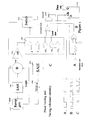
- Figure 9 is a schematic diagram illustrating the gap detection logic circuit 116 of Figure 8 in greater detail.
- the circuit has two inputs and two outputs, corresponding to the inputs and outputs shown in Figure 8.
- the inputs are a "clock” input for receiving the transponder clock signal and an "RF power” line to monitor the presence of received RF power from the interrogator.
- the outputs of the circuits are a "code enable” output to the code generator 112, and a switch control output “SW control" for controlling the controllable switch S1.
- a power-on reset circuit 120 applies a reset signal to a disable flip flop 122 and resets a random gap generator circuit 124.
- the random gap generator circuit 124 provides an output pulse to a modulator enable flip flop 126 after a pseudo random delay, effectively changing the spacing between successive data transmissions from the transponder.
- a random number generator in the random gap generator circuit is seeded each time a reset signal is received from the power-on reset circuit 120.
- the modulator enable flip flop 126 is configured to start in a reset condition, providing a reset signal to a frame length counter 128 which measures and controls the length of codes transmitted by the code generator 112.
- the Q output of the disable flip flop 122 is fed to the D input of the modulator enable flip flop 126.
- the random gap generator 124 generates an output pulse at pseudo random spacing which toggles the modulator enable flip flop 126. If the D input of this flip flop is high, its Q output becomes high. This serves as a "code enable" signal, enabling the code generator 112.
- This output is also fed to an AND gate 130, which allows the transponder clock signal to the fed to the frame length counter 128, which records one count for each incoming clock pulse as the code generator 112 outputs the transponder's identification code sequence. At the end of the code sequence, the frame length counter overflows, providing a reset signal to the modulator enable flip flop 126.
- the serial input of the shift register 132 is held at logic "zero" and a shift register is so arranged that for each clock pulse the loaded "1" shifts one location to the right.
- the outputs of the shift register are so connected as to clock the latch flip flops at the appropriate clock cycle corresponding with the timing diagram of Figure 7.
- the D inputs of the latch flip flops 134 to 144 are connected to the "RF power" line of the circuit, and the latches either record a "1” or a "zero", depending on the state of the "RF power” line when the "1" propagating along the shift register clocks the appropriate latch.
- the state of the latch flip flops 134 to 144 will correspond to a predetermined sequence of 1's and zeros, which is decoded by several gates comprising invertors 146 and 148, and multiple input AND gates 150 and 152.
- the AND gate 150 When the correct turn-off modulation is received, a rising edge is output by the AND gate 150, which is fed to the clock input of the disable flip flop 122, disabling further toggling of the modulator enable flip flop 126. If a second turn-off signal is detected, the output of the AND gate 152 goes high, raising the "SW control" output, and disabling the onboard clock generator of the transponder.
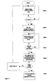
- Figure 10 shows the operation of the above described version of the operation of the transponder in a flow chart format.
- transponders of the invention are used to "tag" articles of merchandise in a retail outlet.
- an interrogator at a till or check-out transmits interrogation signals to transponders in respect of articles of merchandise, and effectively sends turn-off signals to these transponders when they are successfully identified.
- the transponder is disabled for a predetermined period (say, ten minutes). The customer then passes through an exit at which a second interrogator is located. Those transponders which have been disabled by correct processing at the check-out will not respond to the interrogation signals from the interrogator at the exit. However, transponders in articles which have been shoplifted will be detected by the interrogator at the exit, which can generate an appropriate alarm signal.
- transponders described above are relatively robust and inexpensive, and can be applied to a variety of different articles, as mentioned above.
- a single interrogator would not be required to identify transponders associated with completely different types of articles.
- an interrogator used in a supermarket for stock-taking purposes would not be required to identify motor vehicles. If each interrogator were required to identify all possible transponders, an unacceptably large amount of information would need to be stored in the interrogator, and the validation processing of the interrogator would become excessive.
- interrogators and transponders intended for use with different categories of articles are allocated codes of different lengths.
- an identification system used in motor vehicle licence disc validation can be allocated codes which are 24 bits in length, which will not be interpreted as valid by an adjacent reader of vehicle registration numbers which operates with a 22 bit code. Even if transponders of the two systems are transmitting their response signals simultaneously, the random or pseudo-random delays between response signals will ensure that transponders of both systems will eventually be heard.
Abstract
Description
- This invention relates to an identification system comprising an interrogator and a plurality of transponders.
- South African Patent application No. 92/0039 describes an identification system which comprises an interrogator and a number of individual transponders, each transponder being associated with an article to be identified. The articles to be identified may be vehicles, items of stock in a supermarket or warehouse, or humans, for example.
- In the system described in the abovementioned patent application, it is possible under extreme circumstances that the signal from one transponder which is relatively far away from the interrogator could be swamped by the signal from a nearby transponder, leading to non-identification of the transponder which is further away.
- It is an object of the invention to improve the reliability of transponder identification in a system of the kind referred to above.
- According to the invention an identification system comprises an interrogator and a plurality of transponders, the interrogator including transmitter means for transmitting an interrogation signal to the transponder, receiver means for receiving a response signal from the transponder, and processor means for identifying the transponder from data in the response signal; each transponder comprising receiver means for receiving the interrogation signal, a transponder clock generator, a code generator, transmitter means, and a modulator connected to the code generator, so that on receipt of the interrogation signal the transponder transmits a response signal containing data which identifies the transponder, the interrogator being adapted to detect successful reception of a response signal from any transponder, to derive a synchronisation signal from the response signal of that transponder, and to modify the interrogation signal synchronously with the response signal to indicate successful reception of the response signal, each transponder including means responsive to a respective modification of the interrogation signal to cease transmission of its response signal.
- Preferably, the interrogator includes clock extraction means for extracting a clock signal from the response signal which is used to synchronise the modification of the interrogation signal with the response signal.
- The clock extraction means may be adapted to generate a pseudo transponder clock signal which follows the frequency of the extracted transponder clock signal.
- Preferably, the clock extraction means includes a voltage controlled oscillator which generates the pseudo transponder clock signal, and extracted clock monitor means which monitors the presence of the extracted transponder clock signal and which controls the voltage controlled oscillator to maintain the frequency of the pseudo transponder clock signal constant in the absence of the extracted transponder clock signal.
- The interrogator may include timing reference means arranged to generate an output voltage for controlling the voltage controlled oscillator, the output voltage being related initially, when a transponder response signal is received, to the value of a synchronisation code in the transponder response signal.
- The timing reference means may be arranged to generate a voltage ramp, the voltage value reached by the ramp being related to the duration of a synchronisation bit in the transponder response signal.
- The interrogator may be adapted to modify the interrogation signal for a first predetermined number of transponder clock periods, a second predetermined number of transponder clock periods after successful reception of the transponder response signal by the interrogator.
- In a preferred embodiment the interrogation signal is modified by being interrupted.
- The transponder may include logic circuitry arranged to monitor the modification of the interrogation signal and to cause the transponder to cease transmission of its response signal only if the modification of the interrogation signal has a duration related to the duration of a predetermined number of transponder clock periods.
- The logic circuitry may be arranged to monitor the modification of the interrogation signal over a period corresponding to a single transponder clock period.
- The interrogator may be adapted to modify the interrogation signal at least a second time for a third predetermined number of transponder clock periods, a fourth predetermined number of transponder clock periods after successful reception of the transponder response signal by the interrogator.
- The transponder preferably includes control means arranged to detect the second modification of the interrogation signal and to disable the transponder for a predetermined time after the transponder ceases to receive the interrogation signal.
- The predetermined time is preferably determined by a timing circuit comprising a charge storage device which is arranged to be charged by energy derived from the interrogation signal, and to be discharged at a controlled rate after the transponder ceases to receive the interrogation signal.
- The modification of the interrogation signal preferably comprises a transition which occurs at a controlled rate to keep the maximum frequencies generated by the transition within an acceptable range.
- In an alternative embodiment of the system, particularly suitable for use in anti-theft applications, the means responsive to a modification of the interrogation signal is adapted to disable the transponder for a predetermined period of time.
- This allows a transponder attached to an article in a retail outlet to be disabled at a till or check-out, so that it does not respond to interrogation signals from an interrogator at an exit.
- Further according to the invention there is provided a transponder for use in the system defined above, the transponder comprising receiver means for receiving an interrogation signal, a transponder clock generator, a code generator, transmitter means, and a modulator connected to the code generator, so that on receipt of the interrogation signal the transponder transmits a response signal containing data which identifies the transponder, the transponder further comprising means responsive to a respective modification of the interrogation signal synchronous with the response signal and indicating successful identification of the transponder from its response signal to cease transmission of its response signal.
- The transponder may include logic circuitry arranged to monitor the modification of the interrogation signal and to cause the transponder to cease transmission of its response signal only if the modification of the interrogation signal has a duration related to the duration of a predetermined number of transponder clock periods.
- Preferably, the transponder logic circuitry is arranged to monitor the modification of the interrogation signal over a period corresponding to a single transponder clock period.
- The means responsive to a modification of the interrogation signal may be adapted to disable the transponder for a predetermined period of time.
- The transponder may include control means arranged to detect a second modification of the interrogation signal and to disable the transponder for a predetermined time after the transponder ceases to receive the interrogation signal.
- The predetermined time may be determined by a timing circuit comprising a charge storage device which is arranged to be charged by energy derived from the interrogation signal, and to be discharged at a controlled rate after the transponder ceases to receive the interrogation signal.
-
- Figure 1
- is a simplified block schematic diagram of an interrogator according to the invention;
- Figure 2
- is a diagram indicating schematically the basic operation of a transponder of the invention;
- Figure 3
- is a flow chart illustrating the operation of the interrogator of Figure 1 in use;
- Figure 4
- is a timing diagram illustrating the waveforms found in various parts of the interrogator circuitry;
- Figure 5
- is a schematic diagram of synchronisation circuitry of the interrogator circuit of Figure 1;
- Figure 6
- is a timing diagram illustrating the operation of a first version of the identification system, showing the interaction of a transponder and the interrogator;
- Figure 7
- is a timing diagram of a second embodiment of the identification system;
- Figure 8
- is a simplified block schematic diagram of a transponder according to a second embodiment of the invention;
- Figure 9
- is a schematic diagram of the gap detection logic circuit of Figure 8; and
- Figure 10
- is a flow chart illustrating the operation of the transponder of Figure 8.
- This invention relates to an identification system similar to that described in South African Patent Application No. 92/0039, the contents of which are incorporated herein by reference. One example of the identification system comprises an interrogator or reader which transmits interrogation signals at a power of approximately 15W and at a frequency of approximately 915 MHz to a number of passive transponders. The transponders derive a power supply from energy in the interrogation signal, and modulate a portion of the energy received from the interrogator with an identification code to generate a response signal, which is transmitted back to the interrogator.
- The transponder can use separate receiver and transmitter antennas, or a single antenna can be utilised for both reception and transmission. The response signal can be generated by modulating the reflectivity of such an antenna, instead of using a modulator to redirect energy from the receiver antenna to the transmitter antenna. Alternatively, the transponder can be independently powered and may generate its own response signal.
- The system described in the abovementioned patent application provides for each transponder to wait for a random or pseudo-random period after receiving an interrogation signal from the interrogator, before transmitting its own response signal. Successful identification of any transponder is indicated by a brief interruption or other modification of the interrogation signal, following closely on the successful reception of a response signal of any particular transponder. This acts as a turn-off signal to the relevant transponder. The random or pseudo-random delay in the generation of response signals, in response to repeated interrogation signals, ensures that all transponders will eventually be identified by the interrogator.
- Normally, if two transponders transmit respective response signals substantially simultaneously, the interrogator will not successfully identify either of the transponders, due to interference between the response signals. In response to a subsequent interrogation signal, the two transponders will transmit further response signals with respective new random or pseudo-random delays, and will then be detected. However, in an extreme case of the above situation, one of the two transponders may be much closer to the interrogator than the other, so that its response signal swamps the simultaneously transmitted response signal of the other. In this situation, the interrogator may successfully receive the response signal of the nearer of the two transponders, and will then indicate successful reception of that response signal by modifying its interrogation signal, to instruct the nearer transponder to turn itself off. This may be interpreted by both transponders to mean that their respective response signals have been successfully received, so that they both shut off. This will result in the second transponder not being counted.
- In order to address the above worst case scenario, and generally to improve the reliability of detection of transponders of this kind, the interrogator includes a synchronisation circuit which extracts a clock signal from a successfully received transponder response signal, and which synchronises the interruption of the interrogation signal which is used to confirm successful reception of a response signal with the operation of the relevant transponder. Because each transponder has its own internal clock, the frequency of which depends on the power supply voltage derived from the interrogation signal, as well on the tolerance of the clock components in the transponder, the clock frequencies of different transponders vary relatively widely. Thus, by synchronising the shutting-off of the interrogation signal with the clock frequency of the relevant transponder, the chance of another transponder having transmitted its response signal substantially simultaneously, and also having a substantially identical clock frequency, is made remote. This improves the reliability of detection substantially.
- Figure 1 shows the synchronisation circuit of the interrogator. The circuit includes an
amplifier 10 which amplifies the received response signal from the transponder which is responding to an interrogation signal from the interrogator. This signal carries a transponder identification code in a Manchester code format. The signal is fed to a transponderclock extraction circuit 12, adata extraction circuit 14, and a start detect circuit 16. The extracted data and the extracted clock are sent to a microprocessor 18 for code validation along with a "Busy" signal from anactivity indicator circuit 34, which is generated when both the start detect circuit 16 and an extracted clock monitor circuit 20 provide an output, indicating that the hardware is busy processing a received code. The start detect circuitry 16 monitors the output of theamplifier 10 to determine when a transponder response code starts by looking for the quiet bits at the start of a received code, and provides an output to theactivity indicator circuit 34 when these quiet bits are detected. If the activity indicator circuit simultaneously receives an output from the extracted clock monitor circuit 20, it sends a "Busy" signal to the microprocessor to initiate a decoding cycle. - The
clock extraction circuit 12 monitors all the transitions in the received Manchester code, only allowing the transitions occurring within a certain tolerance about the middle of the bit period to generate clock pulses. The output pulse train of the transponderclock extraction circuit 12 is fed to aphase comparator circuit 22 and compared with the output of a voltage controlled oscillator (VCO) 26 in order to modify a timing reference voltage (Vref) held at the output of the timing reference circuit. This reference enables the VCO 26 to generate a "pseudo transponder clock" frequency locked to the extracted transponder clock frequency at the time the last bit of the transponder code was sent. At the same time the extracted clock monitoring circuit 20 monitors the extracted clock. When the last bit of the transponder code has been received no more transponder clock pulses can be extracted and the extracted clock monitor circuit 20 signals the VCO 26 to hold its present output frequency, corresponding to the transponder clock frequency at the time of transmission of the last bit of data from the transponder. - The output of the VCO 26 is fed to an interrogator
shutdown logic circuit 28 which controls the operation of the interrogator's transmitter circuitry 30, in conjunction with a "Valid code" signal from the microprocessor 18 via alogic circuit 32. On successful reception of the response signal by the interrogator, the interrogation signal is modified in order to notify the relevant transponder that its response was received and that it must cease further transmissions of its code. - The operation of a transponder is shown schematically in Figure 2. When the transponder receives an interrogation signal, it modulates its own identification code onto the interrogation signal and transmits a response signal back to the interrogator. The transponder internal logic then monitors the interrogation signal for a "turn-off" instruction, represented by a brief interruption in the interrogation signal. If the turn-off instruction is detected, the transponder ceases its transmission. If no turn-off instruction is detected, the transponder outputs its identification code again, after a random or pseudo-random delay, in response to the next interrogation signal, and the process is repeated.
- The code transmitted by a transponder, as shown in Figure 2, is comprised of a number of quiet bits, followed by a synchronisation bit, followed in turn by the Manchester code containing the transponder identification data. A quiet bit is a bit period where nothing (logic LOW) is transmitted and should be distinguished from a Manchester ZERO bit, in which a LOW is transmitted in the first half of the bit period and a HIGH during the second half. In Manchester code a positive or negative transition always occurs in the middle of the bit period. This fact is used by the interrogator synchronisation circuit to extract the clock used to generate the Manchester code in the transponder. The synchronisation (sync) bit is a logic ONE bit, which when transmitted in Manchester format is combined with the clock in such a way that the Manchester bit is HIGH in the first half of the bit and LOW in the second half of the bit when the quiet period is LOW. Since the timing reference is derived from measuring the pulse width in the first half of the Manchester representation of the sync bit it is important that this pulse occurs in the first half of the bit and not in the second half of the bit.
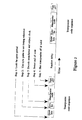
- The flow diagram of Figure 3 shows the steps that the interrogator hardware goes through, while some of the associated waveforms are shown in Figure 4.
- Step 1:
- The output of the
amplifier 10 is monitored for the quiet bits in order to find the start of the transponder identification code. The first bit sent after the quiet bits is a synchronisation bit which is used to determine the period and hence the frequency of the code. A busy signal from theactivity indicator 34 is sent to the microprocessor 18 to indicate the start of a decode cycle. - Step 2:
- A constant current source in the
timing reference circuit 24 generates a timing reference ramp voltage Vref which is sampled for the duration of the sync pulse and then held. This reference voltage relates directly to the clock frequency of the code. - Step 3:
- The timing reference ramp voltage is continuously generated and the voltage compared to a weighted version of the reference. The waveforms shown in Figure 4 show how at 1.5 times the reference voltage the data is latched and at twice the reference voltage the clock is generated which is used by the microprocessor 18 to read the data at the output of the
data extraction circuit 14. The timing reference ramp is reset when the extracted clock pulse occurs within the accepted tolerance around twice the reference voltage. The ramp is sampled and held when the clock occurs and compared to the reference which is modified in order to track the clock frequency of the transponder. - Step 4:
- When no more clock pulses are received (after the last code bit has been decoded) the ramp is not reset and proceeds to a voltage four times the reference, which activates
step 5. - Step 5:
- At this point the extracted clock monitoring circuit 20 outputs a "hold" signal to the VCO 26 which holds the timing reference voltage at its present value, so that the VCO continues to generate its present output frequency. If the microprocessor determines that the decoded code is valid it enables the interrogator shutdown logic to indicate to the transponder it has been successfully identified. If it is not a valid code, the microprocessor 18 will reset the circuit by sending a "reset" signal to the start detect circuit 16 and it will begin looking for the next code.
- Step 6:
- The interrogator signal is modified in order to indicate to the relevant transponder that it has been successfully identified. In the present embodiment this is achieved by turning off the transmitter 30 for a short period in the precise way described below.
- Figure 5 shows in more detail how the phase locking and clock extraction process occurs. The start detect circuitry 16 monitors the Manchester code at the output of the
amplifier 10 and indicates code activity, which starts thereference acquisition step 2. The output of aramp generator 36 is sampled and held by a sample and hold circuit 38 at the end of the sync pulse. This reference voltage (Vref) is multiplied by four by an amplifier 40 and used to generate a number of different reference levels by means of a divider andcomparator network 42. The timing ramp is continuously generated and compared to the reference network in order to determine what action to take. At 1.5 times the held reference voltage we are in the first half of a Manchester bit period, and the state is latched into a D-type flip-flop 66. When the state transition occurs within its tolerance (1.8 Vref - 2.2 Vref) in the middle of the bit period, the extracted clock pulse is generated. This pulse is used by the microprocessor 18 to read the latched output of the D-type flip-flop. This action is repeated for the duration of the code and the associated extracted clock. These generated references are based on the fact that the held reference voltage is proportional to a pulse width of half a bit period measured in the first half of the sync bit period. - When a clock pulse occurs a phase comparator sample and hold
circuit 46 samples and holds the value of the timing reference ramp and compares this, after dividing it by two in adivider circuit 48, to the held timing reference (Vref). If any difference occurs a portion of the difference is combined by an adder 50 with the reference (Vref) in order to pull the reference, and hence the generated clock frequency, towards the new value of the extracted transponder clock frequency. When the code ends no further clock can be extracted resulting in theramp generator 36 not being reset. The ramp voltage then reaches four times Vref and the output of thecomparator 42 operates alogic switch 52 which resets theramp generator 36 and proceeds to generate pseudo clock pulses at twice the updated timing reference period (Vref). - The microprocessor 18 reads the data out signal on each clock pulse and determines the validity of the code by means of an error detection algorithm. In the present embodiment a simple parity check algorithm is used. If the code passes the check the microprocessor allows the interrogator shutdown logic to modify the interrogator signal and sends the code on to the processing circuitry of the interrogator system via a
system interface 54. - Referring now to Figure 6, a waveform diagram shows diagrammatically how the interrogator synchronises its brief shut-down or "turn-off" signal with the operation of the transponder. The diagram of Figure 6 shows a
modulation signal 56 which is generated by the transponder, and which finishes on period N + 1 of the transponder clock waveform 58. Two clock periods later, at clock period N + 3, the transponder logic circuitry checks that the interrogation signal is still being received. Immediately after the transponder clock period N+3 the interrogator shuts off its interrogation signal, reducing itsoutput power 60 to zero, and remains off until the end of the transponder clock period N+6. At the end of the clock period N+6, the transponder logic checks that the interrogation signal is still absent. The interrogation signal is then restored to full power. At clock period N+7, the transponder logic checks whether the interrogation signal is present again. The check is repeated at clock period N+8. If all of the checks are correct, the transponder decides that the turn-off signal from the interrogator applies to it, and disables the transmission of further response signals. The transponder remains off until such time as the interrogation signal has remained off for a predetermined time, allowing the resetting of all transponders, and until the interrogation signal is restored subsequently. - The
waveform 62 in Figure 6 is a pulse generated by the data extraction and code validation circuits of the interrogator on detection of a valid response signal code from a transponder, while thewaveform 64 is a transponder enable signal generated by the internal logic circuitry of the transponder. As can be seen from the diagram, the transponder enable signal changes state at the end of the transponder clock period N+8, after confirmation of the turn-off signal from the interrogator. - To avoid generating undesired radio frequency interference, the interrogation signal is not shut-off or restored instantaneously, but is shut-off and restored at a controlled rate by the interrogator shut-down
logic circuit 28 over at least one transponder clock period, as shown in Figure 6. The rise time and fall time of the turn-off/turn-on sequence are controlled to keep the maximum frequencies generated by the transitions within an acceptable range. This is achieved by a filter circuit at the input of the transmitter 30 which limits the rise and fall times of the driving signal applied to the transmitter input. - The transponder monitors a "rising edge" at the end of the interrogator turn-off signal rather than a falling edge, since the characteristics of the latter tend to vary more with variations in system capacitance and other component values, and with the power drawn by the transmitter.
- The result of the above described techniques is that the "turn-off" window in the interrogation signal which is monitored by each transponder is effectively only one clock period wide (that is, the clock period between N+6 and N+7), which reduces the likelihood of two transponders both transmitting and shutting down simultaneously. In a system comprising one thousand transponders, the likelihood of error is reduced to approximately 0.01%.
- In certain applications, it may be necessary for the transponders to be interrogated more than once, with short time intervals between interrogations, and subsequently for them to be interrogated at longer time intervals. An example of such an application arises when transponders of the invention are used to identify items of stock in a supermarket. When a delivery vehicle arrives at the supermarket, the contents of the vehicle are scanned by an interrogator, and the resulting print-out or display is compared with a delivery invoice or inventory. If any discrepancies are noted, the interrogation process may need to be repeated in a relatively small space of time. This procedure operates as described above.
- At the supermarket check-out, when a customer has filled a trolley with various items, each bearing a transponder, the transponders are reactivated and read by an interrogator connected to a till. In order to prevent theft in the case of a self-service check-out, the interrogator sends a supplementary turn-off signal to the transponder to turn it off for a length of time after it has been removed from the interrogation field. At the exit of the supermarket a security check-out is located, capable of detecting any transponders which have not been rendered inactive by this procedure. Some time after the customer has left the supermarket, the transponders become active once more, allowing them to be used at home. For example, a customer could have an interrogator at home, which could be used to read the contents of a pantry, to determine which items need to be re-purchased. (Otherwise, the transponders can be removed or destroyed after they have passed through the check-out.)
- In order to implement this aspect of the invention, the transponder is designed to look for two turn-off signals in succession. The transponder responds to the first turn-off signal as described above. When this turn-off signal is detected, the transponder ceases further transmissions as long as it remains in the interrogator's field. The transponder now looks for a second turn-off signal. If this second turn-off signal is detected, the transponder charges up a capacitor, using energy from the interrogation signal, which disables the code generator circuitry of the transponder for a predetermined period (say, ten minutes) after the transponder has been removed from the interrogator's field.
- Figure 8 shows an example of a transponder which is able to respond to dual turn-off signals. The transponder comprises a receive/transmit antenna 110, the output of which is fed via diodes D1 and D2 to a power supply capacitor C1. When the capacitor C1 is sufficiently charged, the transponder circuitry is activated, and the transponder begins to transmit its identification code as described above. The power supply from the capacitor C1 powers a
code generator circuit 112 and a clock generator circuit 114 which receives a "clock enable" signal via a resistor R. The code generator, which in normal operating mode is enabled by a "code enable" signal from a gapdetection logic circuit 116, sends its output to a modulator circuit 118, which modulates the transponder identification code from thecode generator 112 onto the interrogation signal, at a clock frequency determined by the clock generator circuit 114. - If the response signal from the transponder is successfully detected by the interrogator, the interrogator transmits a first turn-off signal, as shown in Figure 7, between transponder clock periods N+3 and N+8. This interruption in the interrogation signal is detected by the gap
detection logic circuit 116 and the "code enable" signal is removed from the code generator, disabling the transponder. The gapdetection logic circuit 116 now monitors the interrogation signal for a second turn-off signal, which, in Figure 7, occurs between transponder clock periods N+10 and N+14. If this second turn-off signal is detected, the gapdetection logic circuit 116 sends a switch control signal to a controllable switch S1, closing the switch. This allows a timing capacitor CT to charge up via a diode D3. When this capacitor has reached a predetermined level of charge, it turns on a field effect transistor T1, removing the "clock enable" signal from the clock generation circuit 114. This disables the transponder, and the transponder remains in this state until it is removed from the interrogator's field. When this happens, the timing capacitor CT is discharged through a parallel leakage resistor RL. Once the timing capacitor CT has discharged fully, the transponder will again operate normally, and will respond to interrogation signals. However, if the transponder is moved into an interrogation field at any time while the capacitor CT is still charged, the clock generation circuit 114 will continue to be disabled, inhibiting operation of the transponder. - Figure 9 is a schematic diagram illustrating the gap
detection logic circuit 116 of Figure 8 in greater detail. The circuit has two inputs and two outputs, corresponding to the inputs and outputs shown in Figure 8. The inputs are a "clock" input for receiving the transponder clock signal and an "RF power" line to monitor the presence of received RF power from the interrogator. The outputs of the circuits are a "code enable" output to thecode generator 112, and a switch control output "SW control" for controlling the controllable switch S1. - When power is initially applied to the gap
detection logic circuit 116, a power-onreset circuit 120 applies a reset signal to a disableflip flop 122 and resets a randomgap generator circuit 124. The randomgap generator circuit 124 provides an output pulse to a modulator enableflip flop 126 after a pseudo random delay, effectively changing the spacing between successive data transmissions from the transponder. A random number generator in the random gap generator circuit is seeded each time a reset signal is received from the power-onreset circuit 120. The modulator enableflip flop 126 is configured to start in a reset condition, providing a reset signal to aframe length counter 128 which measures and controls the length of codes transmitted by thecode generator 112. - The Q output of the disable
flip flop 122 is fed to the D input of the modulator enableflip flop 126. Therandom gap generator 124 generates an output pulse at pseudo random spacing which toggles the modulator enableflip flop 126. If the D input of this flip flop is high, its Q output becomes high. This serves as a "code enable" signal, enabling thecode generator 112. This output is also fed to an ANDgate 130, which allows the transponder clock signal to the fed to theframe length counter 128, which records one count for each incoming clock pulse as thecode generator 112 outputs the transponder's identification code sequence. At the end of the code sequence, the frame length counter overflows, providing a reset signal to the modulator enableflip flop 126. This removes the "code enable" signal from the Q output of the modulator enableflip flop 126, and enables a parallel loadright shift register 132, which is loaded with a sequence of zero's except for the first bit (the leftmost bit in Figure 9), which is loaded with a one. Each of sixlatch flip flops 134 to 144 is reset by the output signal from theframe length counter 128. - The serial input of the
shift register 132 is held at logic "zero" and a shift register is so arranged that for each clock pulse the loaded "1" shifts one location to the right. The outputs of the shift register are so connected as to clock the latch flip flops at the appropriate clock cycle corresponding with the timing diagram of Figure 7. The D inputs of thelatch flip flops 134 to 144 are connected to the "RF power" line of the circuit, and the latches either record a "1" or a "zero", depending on the state of the "RF power" line when the "1" propagating along the shift register clocks the appropriate latch. - Should the interrogator have received a perfect identification code from the transponder and have modulated the interrogation signal with an appropriate interruption or turn-off signal, the state of the
latch flip flops 134 to 144 will correspond to a predetermined sequence of 1's and zeros, which is decoded by severalgates comprising invertors gates gate 150, which is fed to the clock input of the disableflip flop 122, disabling further toggling of the modulator enableflip flop 126. If a second turn-off signal is detected, the output of the ANDgate 152 goes high, raising the "SW control" output, and disabling the onboard clock generator of the transponder. - Figure 10 shows the operation of the above described version of the operation of the transponder in a flow chart format.
- The technology described above with reference to Figures 8 and 9 can also be applied to theft prevention application, where the transponders of the invention are used to "tag" articles of merchandise in a retail outlet. In such an application, an interrogator at a till or check-out transmits interrogation signals to transponders in respect of articles of merchandise, and effectively sends turn-off signals to these transponders when they are successfully identified. By means of similar circuitry to that described in Figures 8 and 9, the transponder is disabled for a predetermined period (say, ten minutes). The customer then passes through an exit at which a second interrogator is located. Those transponders which have been disabled by correct processing at the check-out will not respond to the interrogation signals from the interrogator at the exit. However, transponders in articles which have been shoplifted will be detected by the interrogator at the exit, which can generate an appropriate alarm signal.
- The transponders described above are relatively robust and inexpensive, and can be applied to a variety of different articles, as mentioned above. In most cases, a single interrogator would not be required to identify transponders associated with completely different types of articles. For example, an interrogator used in a supermarket for stock-taking purposes would not be required to identify motor vehicles. If each interrogator were required to identify all possible transponders, an unacceptably large amount of information would need to be stored in the interrogator, and the validation processing of the interrogator would become excessive. To cope with this situation, interrogators and transponders intended for use with different categories of articles are allocated codes of different lengths. For example, an identification system used in motor vehicle licence disc validation can be allocated codes which are 24 bits in length, which will not be interpreted as valid by an adjacent reader of vehicle registration numbers which operates with a 22 bit code. Even if transponders of the two systems are transmitting their response signals simultaneously, the random or pseudo-random delays between response signals will ensure that transponders of both systems will eventually be heard.
Claims (21)
- An identification system characterised in that it comprises an interrogator and a plurality of transponders, the interrogator including transmitter means (30) for transmitting an interrogation signal to the transponder, receiver means (10) for receiving a response signal from the transponder, and processor means (18) for identifying the transponder from data in the response signal; each transponder comprising receiver means (110, 116) for receiving the interrogation signal, a transponder clock generator (114), a code generator (112), transmitter means (110), and a modulator (118) connected to the code generator, so that on receipt of the interrogation signal the transponder transmits a response signal containing data which identifies the transponder, the interrogator being adapted to detect successful reception of a response signal from any transponder, to derive a synchronisation signal from the response signal of that transponder, and to modify the interrogation signal synchronously with the response signal to indicate successful reception of the response signal, each transponder including means (116) responsive to a respective modification of the interrogation signal to cease transmission of its response signal.
- An identification system according to claim 1 wherein the interrogator includes clock extraction means (12, 20, 22, 24, 26) for extracting a transponder clock signal from the response signal which is used to synchronise the modification of the interrogation signal with the response signal from the transponder.
- An identification system according to claim 2 characterised in that the clock extraction means (12, 20, 22, 24, 26) is adapted to generate a pseudo transponder clock signal which follows the frequency of the extracted transponder clock signal.
- An identification system according to claim 3 characterised in that the clock extraction means includes a voltage controlled oscillator (26) which generates the pseudo transponder clock signal, and extracted clock monitor means (20) which monitors the presence of the extracted transponder clock signal and which controls the voltage controlled oscillator to maintain the frequency of the pseudo transponder clock signal constant in the absence of the extracted transponder clock signal.
- An identification system according to claim 4 characterised in that the interrogator includes timing reference means (24) arranged to generate an output voltage for controlling the voltage controlled oscillator (26), the output voltage being related initially, when a transponder response signal is received, to the value of a synchronisation code in the transponder response signal.
- An identification system according to claim 5 characterised in that the timing reference means (24) is arranged to generate a voltage ramp, the voltage value reached by the ramp being related to the duration of a synchronisation bit in the transponder response signal.
- An identification system according to any one of claims 2 to 6 characterised in that the interrogator is adapted to modify the interrogation signal for a first predetermined number of transponder clock periods, a second predetermined number of transponder clock periods after successful reception of the transponder response signal by the interrogator.
- An identification system according to claim 7 characterised in that the interrogation signal is modified by being interrupted.
- An identification according to claim 7 or claim 8 characterised in that the transponder includes logic circuitry (116) arranged to monitor the modification of the interrogation signal and to cause the transponder to cease transmission of its response signal only if the modification of the interrogation signal has a duration related to the duration of a predetermined number of transponder clock periods.
- An identification system according to claim 9 characterised in that the transponder logic circuitry (116) is arranged to monitor the modification of the interrogation signal over a period corresponding to a single transponder clock period.
- An identification system according to any one of claims 7 to 10 characterised in that the interrogator is adapted to modify the interrogation signal at least a second time for a third predetermined number of transponder clock periods, a fourth predetermined number of transponder clock periods after successful reception of the transponder response signal by the interrogator.
- An identification system according to claim 11 characterised in that the transponder includes control means (148, 152, SI) arranged to detect the second modification of the interrogation signal and to disable the transponder for a predetermined time after the transponder ceases to receive the interrogation signal.
- An identification system according to claim 12 characterised in that the predetermined time is determined by a timing circuit comprising a charge storage device (CT) which is arranged to be charged by energy derived from the interrogation signal, and to be discharged at a controlled rate after the transponder ceases to receive the interrogation signal.
- An identification system according to any one of claims 1 to 13 characterised in that the modification of the interrogation signal comprises a transition which occurs at a controlled rate.
- An identification system according to claim 1 characterised in that the means (116) responsive to a modification of the interrogation signal is adapted to disable the transponder for a predetermined period of time.
- A transponder for use in the identification system of any one of claims 1 to 15, the transponder being characterised in that it comprises receiver means (110, 116) for receiving an interrogation signal, a transponder clock generator (114), a code generator (112), transmitter means (110), and a modulator (118) connected to the code generator, so that on receipt of the interrogation signal the transponder transmits a response signal containing data which identifies the transponder, the transponder further comprising means (116) responsive to a respective modification of the interrogation signal synchronous with the response signal and indicating successful identification of the transponder from its response signal, to cease transmission of its response signal.
- A transponder according to claim 16 characterised in that the transponder includes logic circuitry (116) arranged to monitor the modification of the interrogation signal and to cause the transponder to cease transmission of its response signal only if the modification of the interrogation signal has a duration related to the duration of a predetermined number of transponder clock periods.
- A transponder according to claim 17 characterised in that the transponder logic circuitry (116) is arranged to monitor the modification of the interrogation signal over a period corresponding to a single transponder clock period.
- A transponder according to any one of claims 16 to 18 characterised in that the means (116) responsive to a modification of the interrogation signal is adapted to disable the transponder for a predetermined period of time.
- A transponder according to any one of claims 16 to 19 characterised in that the transponder includes control means (148, 152, SI) arranged to detect a second modification of the interrogation signal and to disable the transponder for a predetermined period of time after the transponder ceases to receive the interrogation signal.
- A transponder according to claim 19 or claim 20 characterised in that the predetermined time is determined by a timing circuit comprising a charge storage device (CT) which is arranged to be charged by energy derived from the interrogation signal, and to be discharged at a controlled rate after the transponder ceases to receive the interrogation signal.
Applications Claiming Priority (2)
| Application Number | Priority Date | Filing Date | Title |
|---|---|---|---|
| ZA926446 | 1992-08-26 | ||
| ZA926446 | 1992-08-26 |
Publications (2)
| Publication Number | Publication Date |
|---|---|
| EP0585132A1 true EP0585132A1 (en) | 1994-03-02 |
| EP0585132B1 EP0585132B1 (en) | 1998-09-23 |
Family
ID=25582026
Family Applications (1)
| Application Number | Title | Priority Date | Filing Date |
|---|---|---|---|
| EP93306790A Expired - Lifetime EP0585132B1 (en) | 1992-08-26 | 1993-08-26 | Synchronised electronic identification system |
Country Status (15)
| Country | Link |
|---|---|
| US (2) | US5557280A (en) |
| EP (1) | EP0585132B1 (en) |
| JP (1) | JP3290003B2 (en) |
| CN (1) | CN1047667C (en) |
| AT (1) | ATE171547T1 (en) |
| AU (2) | AU656088B2 (en) |
| CA (1) | CA2104829C (en) |
| DE (1) | DE69321179T2 (en) |
| DK (1) | DK0585132T3 (en) |
| ES (1) | ES2121954T3 (en) |
| RU (1) | RU2156540C2 (en) |
| SG (1) | SG48262A1 (en) |
| TW (1) | TW297192B (en) |
| UA (1) | UA37182C2 (en) |
| ZA (1) | ZA936267B (en) |
Cited By (41)
| Publication number | Priority date | Publication date | Assignee | Title |
|---|---|---|---|---|
| US5550547A (en) * | 1994-09-12 | 1996-08-27 | International Business Machines Corporation | Multiple item radio frequency tag identification protocol |
| WO1996034299A1 (en) * | 1995-04-27 | 1996-10-31 | British Technology Group Inter-Corporate Licensing Limited | Interrogator for electronic identification system |
| US5673037A (en) * | 1994-09-09 | 1997-09-30 | International Business Machines Corporation | System and method for radio frequency tag group select |
| US5731691A (en) * | 1995-07-21 | 1998-03-24 | Oki Electric Industry Co., Ltd. | Power supply circuitry for a transponder and operable with infinitesimal power from receiving antenna |
| US5745036A (en) * | 1996-09-12 | 1998-04-28 | Checkpoint Systems, Inc. | Electronic article security system for store which uses intelligent security tags and transaction data |
| WO1998027441A1 (en) * | 1996-12-19 | 1998-06-25 | Micron Communications, Inc. | Methods of processing wireless communication, methods of processing radio frequency communication, and related systems |
| FR2758027A1 (en) * | 1996-12-27 | 1998-07-03 | Gemplus Card Int | REMOTE INTERROGATION COMMUNICATION SYSTEM FOR TRANSMITTING INHIBITION CONTROLS |
| WO1998052142A1 (en) * | 1997-05-14 | 1998-11-19 | Btg International Limited | Enhanced identification system |
| WO1998051143A1 (en) | 1997-05-14 | 1998-11-19 | Btg International Limited | Voluntary milking |
| US5854480A (en) * | 1995-07-18 | 1998-12-29 | Oki Electric Indusry Co., Ltd. | Tag with IC capacitively coupled to antenna |
| US5866891A (en) * | 1995-01-11 | 1999-02-02 | Sony Chemicals Corp. | Transmitter-receiver for non-contact IC card system |
| EP0942387A1 (en) * | 1998-03-12 | 1999-09-15 | Commissariat A L'energie Atomique | Procedure and system for multiple reading of a dynamic collection of labels |
| US5963134A (en) * | 1997-07-24 | 1999-10-05 | Checkpoint Systems, Inc. | Inventory system using articles with RFID tags |
| US6001211A (en) * | 1995-07-18 | 1999-12-14 | Oki Electric Industry Co., Ltd. | Method of producing a tag device with IC capacitively coupled to antenna |
| US6002344A (en) * | 1997-11-21 | 1999-12-14 | Bandy; William R. | System and method for electronic inventory |
| US6025780A (en) * | 1997-07-25 | 2000-02-15 | Checkpoint Systems, Inc. | RFID tags which are virtually activated and/or deactivated and apparatus and methods of using same in an electronic security system |
| FR2785700A1 (en) * | 1998-11-10 | 2000-05-12 | St Microelectronics Sa | METHOD FOR MANAGING AN ELECTRONIC CIRCUIT |
| WO2000043946A1 (en) * | 1999-01-22 | 2000-07-27 | Gemplus | Maintenance of an anticollision channel in an electronic identification system |
| US6150934A (en) * | 1998-01-22 | 2000-11-21 | Em Microelectronic-Marin Sa | Electronic communication system between a base station and transponders |
| US6249212B1 (en) * | 1994-10-05 | 2001-06-19 | Avid Marketing, Inc. | Universal electronic identification tag |
| US6600418B2 (en) | 2000-12-12 | 2003-07-29 | 3M Innovative Properties Company | Object tracking and management system and method using radio-frequency identification tags |
| US6669089B2 (en) | 2001-11-12 | 2003-12-30 | 3M Innovative Properties Co | Radio frequency identification systems for asset tracking |
| WO2004032408A1 (en) * | 2002-10-02 | 2004-04-15 | Battelle Memorial Institute | Wireless communications devices, methods of processing a wireless communication signal, wireless communication synchronization methods and a radio frequency identification device communication method |
| US6762683B1 (en) | 1999-10-26 | 2004-07-13 | Koninklijke Philips Electronics N.V. | Tag device |
| US6784813B2 (en) | 2001-02-12 | 2004-08-31 | Matrics, Inc. | Method, system, and apparatus for remote data calibration of a RFID tag population |
| US6812852B1 (en) | 1994-09-09 | 2004-11-02 | Intermac Ip Corp. | System and method for selecting a subset of autonomous and independent slave entities |
| US6876294B1 (en) | 1998-08-18 | 2005-04-05 | Identec Limited | Transponder identification system |
| US7009496B2 (en) | 2002-04-01 | 2006-03-07 | Symbol Technologies, Inc. | Method and system for optimizing an interrogation of a tag population |
| US7035818B1 (en) | 1997-11-21 | 2006-04-25 | Symbol Technologies, Inc. | System and method for electronic inventory |
| US7195173B2 (en) | 2002-10-25 | 2007-03-27 | Symbol Technologies, Inc. | Optimization of a binary tree traversal with secure communications |
| US7248145B2 (en) | 2000-02-28 | 2007-07-24 | Magellan Technology Oty Limited | Radio frequency identification transponder |
| US7259654B2 (en) | 2000-02-28 | 2007-08-21 | Magellan Technology Pty Limited | Radio frequency identification transponder |
| EP1901251A2 (en) | 1998-08-14 | 2008-03-19 | 3M Innovative Properties Company | Applications for radio frequency identification systems |
| DE112005000319T5 (en) | 2004-02-06 | 2008-07-03 | Zih Corp. | Selection and arbitration method and system |
| EP1950686A2 (en) | 1998-08-14 | 2008-07-30 | 3M Innovative Properties Company | Radio frequency identification method |
| US7616094B2 (en) | 1994-09-09 | 2009-11-10 | Intermec Ip Corp. | Radio frequency identification system with write broadcast capability |
| US7844505B1 (en) | 1997-11-21 | 2010-11-30 | Symbol Technologies, Inc. | Automated real-time distributed tag reader network |
| US7948381B2 (en) | 2004-04-30 | 2011-05-24 | Binforma Group Limited Liability Company | Reversibly deactivating a radio frequency identification data tag |
| US8138922B2 (en) | 2004-04-30 | 2012-03-20 | Binforma Group Limited Liability Company | Deactivating a data tag for user privacy or tamper-evident packaging |
| US9070003B2 (en) | 2011-04-04 | 2015-06-30 | Nxp B.V. | Method for handling collision in an identification system |
| US9152909B2 (en) | 2008-07-21 | 2015-10-06 | Sato Vicinity Pty Ltd | Device having data storage |
Families Citing this family (94)
| Publication number | Priority date | Publication date | Assignee | Title |
|---|---|---|---|---|
| US5557280A (en) * | 1992-08-26 | 1996-09-17 | British Technology Group Limited | Synchronized electronic identification system |
| MY109809A (en) * | 1992-11-18 | 1997-07-31 | British Tech Group Ltd | Detection of multiple articles |
| US5793324A (en) * | 1996-01-19 | 1998-08-11 | Texas Instruments Incorporated | Transponder signal collision avoidance system |
| DE19646153A1 (en) * | 1996-11-08 | 1998-05-14 | Siemens Nixdorf Inf Syst | Shopping cart scanner |
| ATE305670T1 (en) * | 1997-01-21 | 2005-10-15 | Koninkl Philips Electronics Nv | TRANSPONDER MESSAGE TRANSMISSION DEVICE |
| US6038255A (en) * | 1997-06-24 | 2000-03-14 | Ludwig Kipp | Receiver for pulse width modulated transmissions |
| JPH1118608A (en) * | 1997-07-01 | 1999-01-26 | Matsushita Electron Corp | Automatically feeding system for pet |
| US6054925A (en) * | 1997-08-27 | 2000-04-25 | Data Investments Limited | High impedance transponder with improved backscatter modulator for electronic identification system |
| CN1161709C (en) | 1997-09-26 | 2004-08-11 | 数据投资有限公司 | Delayed reset mode model for electronic identification systems |
| GB9724183D0 (en) * | 1997-11-14 | 1998-01-14 | British Tech Group | Identification system |
| US5936527A (en) * | 1998-02-10 | 1999-08-10 | E-Tag Systems, Inc. | Method and apparatus for locating and tracking documents and other objects |
| US6154136A (en) * | 1998-02-26 | 2000-11-28 | Van Eeden; Hendrik Lodewyk | Free running RF identification system with increasing average inter transmission intervals |
| US6909366B1 (en) | 1998-03-04 | 2005-06-21 | Trolley Scan (Proprietary) Limited | Multi-dimensional electronic identification of articles |
| US6154137A (en) | 1998-06-08 | 2000-11-28 | 3M Innovative Properties Company | Identification tag with enhanced security |
| US6724895B1 (en) | 1998-06-18 | 2004-04-20 | Supersensor (Proprietary) Limited | Electronic identification system and method with source authenticity verification |
| CN1137563C (en) * | 1998-06-25 | 2004-02-04 | 格姆普拉斯有限公司 | Short-range interrogation communication system capable of sending inhibit command |
| JP2002522999A (en) | 1998-08-14 | 2002-07-23 | スリーエム イノベイティブ プロパティズ カンパニー | Applications to radio frequency identification systems |
| US6424262B2 (en) | 1998-08-14 | 2002-07-23 | 3M Innovative Properties Company | Applications for radio frequency identification systems |
| FR2785068B1 (en) * | 1998-10-23 | 2003-12-05 | Inside Technologies | ENCODING METHOD AND DEVICE FOR DATA TRANSMISSION BY LOAD MODULATION AND INDUCTIVE COUPLING |
| US6480143B1 (en) | 1998-11-09 | 2002-11-12 | Supersensor (Proprietary) Limited | Electronic identification system |
| EP1026779A3 (en) | 1999-02-01 | 2003-06-04 | Supersensor (Proprietary) Limited | Hydrid antenna arrangement for use with electronic identification systems |
| FR2790622B1 (en) | 1999-03-05 | 2001-06-08 | Berner Fachhochschule Hochschu | TRANSPONDER AND ARCHIVE MANAGER USING SUCH TRANSPONDERS |
| WO2000072461A1 (en) | 1999-05-21 | 2000-11-30 | Koerner Ralph J | Identification system for monitoring the presence/absence of members of a defined set |
| US6329944B1 (en) | 2000-05-12 | 2001-12-11 | Northrop Grumman Corporation | Tag communication protocol & system |
| US6774766B1 (en) * | 2000-07-21 | 2004-08-10 | E-Tag Systems, Inc. | Method for efficiently querying and identifying multiple items on a communication channel |
| WO2002035432A1 (en) | 2000-10-20 | 2002-05-02 | Promega Corporation | Radio frequency identification method and system of distributing products |
| US20020183882A1 (en) | 2000-10-20 | 2002-12-05 | Michael Dearing | RF point of sale and delivery method and system using communication with remote computer and having features to read a large number of RF tags |
| USRE47599E1 (en) | 2000-10-20 | 2019-09-10 | Promega Corporation | RF point of sale and delivery method and system using communication with remote computer and having features to read a large number of RF tags |
| US7253717B2 (en) * | 2000-11-29 | 2007-08-07 | Mobile Technics Llc | Method and system for communicating with and tracking RFID transponders |
| US6951596B2 (en) | 2002-01-18 | 2005-10-04 | Avery Dennison Corporation | RFID label technique |
| US6727803B2 (en) | 2001-03-16 | 2004-04-27 | E-Tag Systems, Inc. | Method and apparatus for efficiently querying and identifying multiple items on a communication channel |
| JP3927378B2 (en) * | 2001-05-22 | 2007-06-06 | 株式会社日立製作所 | Article management system using interrogator |
| US6988667B2 (en) | 2001-05-31 | 2006-01-24 | Alien Technology Corporation | Methods and apparatuses to identify devices |
| US7137000B2 (en) | 2001-08-24 | 2006-11-14 | Zih Corp. | Method and apparatus for article authentication |
| US7193504B2 (en) * | 2001-10-09 | 2007-03-20 | Alien Technology Corporation | Methods and apparatuses for identification |
| US6915551B2 (en) * | 2002-08-02 | 2005-07-12 | Matrics, Inc. | Multi-barrel die transfer apparatus and method for transferring dies therewith |
| US7023347B2 (en) * | 2002-08-02 | 2006-04-04 | Symbol Technologies, Inc. | Method and system for forming a die frame and for transferring dies therewith |
| JP4024619B2 (en) * | 2002-08-09 | 2007-12-19 | 株式会社日立製作所 | Information reading device for semiconductor devices |
| US6975206B2 (en) * | 2002-08-30 | 2005-12-13 | Intellectual Property, Llc | Method for communication between central terminal and multiple transponders |
| AU2002951699A0 (en) * | 2002-09-27 | 2002-10-17 | Tagsys Australia Pty Ltd | Method of avoiding continued destructive tag collisions in an slotted aloha anti-collision scheme |
| EP1406208A1 (en) * | 2002-10-02 | 2004-04-07 | EM Microelectronic-Marin SA | Identification method for multiple transponders within the interrogation field of a reader having a plurality of antennas |
| US7575234B2 (en) * | 2003-04-17 | 2009-08-18 | Bally Gaming, Inc. | Wireless monitoring of playing cards and/or wagers in gaming |
| US7223320B2 (en) * | 2003-06-12 | 2007-05-29 | Symbol Technologies, Inc. | Method and apparatus for expanding a semiconductor wafer |
| US8102244B2 (en) | 2003-08-09 | 2012-01-24 | Alien Technology Corporation | Methods and apparatuses to identify devices |
| JP4370597B2 (en) * | 2003-09-11 | 2009-11-25 | 株式会社エフ・イー・シー | IC chip for identification, data reading method, and data writing method |
| US7068028B2 (en) * | 2003-09-12 | 2006-06-27 | Intellectual Property Llc | Method and apparatus for metal target proximity detection at long distances |
| US7716160B2 (en) | 2003-11-07 | 2010-05-11 | Alien Technology Corporation | Methods and apparatuses to identify devices |
| JP4317431B2 (en) * | 2003-12-03 | 2009-08-19 | 株式会社エフ・イー・シー | IC chip for identification and method for reading the data |
| EP1692883B1 (en) * | 2003-12-09 | 2010-06-02 | Intelleflex Corporation | Battery activation circuit |
| EP1697875B1 (en) * | 2003-12-19 | 2009-07-01 | Nxp B.V. | Synchronization during anti-collision |
| EP1733337A4 (en) * | 2004-01-12 | 2008-06-25 | Symbol Technologies Inc | Radio frequency identification tag inlay sortation and assembly |
| US7370808B2 (en) * | 2004-01-12 | 2008-05-13 | Symbol Technologies, Inc. | Method and system for manufacturing radio frequency identification tag antennas |
| US20050224590A1 (en) * | 2004-04-13 | 2005-10-13 | John Melngailis | Method and system for fabricating integrated circuit chips with unique identification numbers |
| US6966734B2 (en) * | 2004-04-23 | 2005-11-22 | Toteff Thomas S | Dual purpose track for holding wheel chocks and strap clips to tie down dirt bikes to trailers |
| US7336183B2 (en) | 2004-04-30 | 2008-02-26 | Kimberly-Clark Worldwide, Inc. | Decommissioning an electronic data tag |
| US7151455B2 (en) | 2004-04-30 | 2006-12-19 | Kimberly-Clark Worldwide, Inc. | Activating a data tag by load or orientation or user control |
| FR2871968B1 (en) * | 2004-06-16 | 2006-09-08 | Gemplus Sa | SYNCHRONOUS PHASE CONTACTLESS DEMODULATION METHOD, DEMODULATOR AND READER |
| US20060012387A1 (en) * | 2004-06-29 | 2006-01-19 | Symbol Technologies, Inc. | Systems and methods for testing radio frequency identification tags |
| EP1784803A4 (en) | 2004-08-17 | 2010-07-14 | Symbol Technologies Inc | Singulation of radio frequency identification (rfid) tags for testing and/or programming |
| US7500307B2 (en) | 2004-09-22 | 2009-03-10 | Avery Dennison Corporation | High-speed RFID circuit placement method |
| US20060125605A1 (en) * | 2004-12-13 | 2006-06-15 | Atmel Germany Gmbh | Method for locating a backscatter-based transponder |
| US7689195B2 (en) * | 2005-02-22 | 2010-03-30 | Broadcom Corporation | Multi-protocol radio frequency identification transponder tranceiver |
| GB2423674A (en) * | 2005-02-25 | 2006-08-30 | Hewlett Packard Development Co | Writing to transponder devices |
| US20060223225A1 (en) * | 2005-03-29 | 2006-10-05 | Symbol Technologies, Inc. | Method, system, and apparatus for transfer of integrated circuit dies using an attractive force |
| US20060225273A1 (en) * | 2005-03-29 | 2006-10-12 | Symbol Technologies, Inc. | Transferring die(s) from an intermediate surface to a substrate |
| US7474223B2 (en) * | 2005-04-18 | 2009-01-06 | Warsaw Orthopedic, Inc. | Method and apparatus for implant identification |
| US7623034B2 (en) | 2005-04-25 | 2009-11-24 | Avery Dennison Corporation | High-speed RFID circuit placement method and device |
| US7327261B2 (en) * | 2005-07-27 | 2008-02-05 | Zih Corp. | Visual identification tag deactivation |
| US8550464B2 (en) | 2005-09-12 | 2013-10-08 | Bally Gaming, Inc. | Systems, methods and articles to facilitate playing card games with selectable odds |
| JP4524231B2 (en) * | 2005-09-13 | 2010-08-11 | 富士通フロンテック株式会社 | Communication system and communication apparatus |
| US8078103B2 (en) | 2005-10-31 | 2011-12-13 | Zih Corp. | Multi-element RFID coupler |
| US20070107186A1 (en) * | 2005-11-04 | 2007-05-17 | Symbol Technologies, Inc. | Method and system for high volume transfer of dies to substrates |
| US20070131016A1 (en) * | 2005-12-13 | 2007-06-14 | Symbol Technologies, Inc. | Transferring die(s) from an intermediate surface to a substrate |
| US20070139057A1 (en) * | 2005-12-15 | 2007-06-21 | Symbol Technologies, Inc. | System and method for radio frequency identification tag direct connection test |
| US7555826B2 (en) * | 2005-12-22 | 2009-07-07 | Avery Dennison Corporation | Method of manufacturing RFID devices |
| US20070158024A1 (en) * | 2006-01-11 | 2007-07-12 | Symbol Technologies, Inc. | Methods and systems for removing multiple die(s) from a surface |
| US8018323B2 (en) * | 2006-01-30 | 2011-09-13 | Baohua Qi | RFID sensor device based on pulse-processing |
| US20070244657A1 (en) * | 2006-04-11 | 2007-10-18 | Drago Randall A | Methods and systems for testing radio frequency identification (RFID) tags having multiple antennas |
| US8038153B2 (en) | 2006-05-23 | 2011-10-18 | Bally Gaming, Inc. | Systems, methods and articles to facilitate playing card games |
| US7753779B2 (en) | 2006-06-16 | 2010-07-13 | Bally Gaming, Inc. | Gaming chip communication system and method |
| US8647191B2 (en) | 2006-09-26 | 2014-02-11 | Bally Gaming, Inc. | Resonant gaming chip identification system and method |
| US8820639B2 (en) | 2006-11-03 | 2014-09-02 | Assa Abloy Ab | Security feature RFID card |
| DE102007007309A1 (en) * | 2007-02-07 | 2008-08-14 | Atmel Germany Gmbh | Method for at least temporarily unlocking a bidirectional communication and transponder |
| US7710275B2 (en) | 2007-03-16 | 2010-05-04 | Promega Corporation | RFID reader enclosure and man-o-war RFID reader system |
| US8272945B2 (en) | 2007-11-02 | 2012-09-25 | Bally Gaming, Inc. | Game related systems, methods, and articles that combine virtual and physical elements |
| US20100058424A1 (en) * | 2008-08-26 | 2010-03-04 | Comcast Cable Holdings, Llc | System and method for controlling signal traffic peaks on a video interactive network |
| DE102008050988A1 (en) * | 2008-09-01 | 2010-03-04 | Gerd Reime | Identification element with an optical transponder |
| EP2164023B1 (en) * | 2008-09-11 | 2017-05-17 | Rockwell Automation Germany GmbH & Co. KG | Enhanced RFID output control |
| EP2166485B1 (en) * | 2008-09-19 | 2016-02-24 | Rockwell Automation Germany GmbH & Co. KG | RFID Reaction time reduction |
| ES2444712B1 (en) * | 2012-07-26 | 2014-12-10 | Consejo Superior De Investigaciones Científicas (Csic) | WIRELESS TELEMETRIC SYSTEM FOR MONITORING OF STATIC AND DYNAMIC MAGNITUDES. |
| SE538020C2 (en) * | 2014-04-01 | 2016-02-09 | Utvecklingsavdelningen I Sverige Ab | Method, system, transponder and a position detection device for an accurate measurement of a position |
| RU2688899C2 (en) * | 2016-11-21 | 2019-05-23 | Федеральное государственное казенное военное образовательное учреждение высшего образования "Военный учебно-научный центр Военно-воздушных сил "Военно-воздушная академия имени профессора Н.Е. Жуковского и Ю.А. Гагарина" (г. Воронеж) Министерства обороны Российской Федерации | Method of identifying radar targets |
| KR20220022618A (en) * | 2020-08-19 | 2022-02-28 | 에스케이하이닉스 주식회사 | Clock monotoring circuit |
| CN117361042B (en) * | 2023-10-30 | 2024-04-02 | 中国人民解放军陆军工程大学 | Urban underground material transportation system and working method thereof |
Citations (5)
| Publication number | Priority date | Publication date | Assignee | Title |
|---|---|---|---|---|
| US4072946A (en) * | 1972-09-26 | 1978-02-07 | Christiaan Huygenslaboratorium B.V. | Method and apparatus for measuring the distance between two stations |
| US4128835A (en) * | 1977-08-23 | 1978-12-05 | Arinc Research Corporation | Method and apparatus for measuring distance between an aircraft and a ground station |
| EP0161779A1 (en) * | 1984-04-03 | 1985-11-21 | Senelco Limited | Identification systems |
| FR2621134A1 (en) * | 1987-09-26 | 1989-03-31 | Matsushita Electric Works Ltd | MOBILE OBJECT DISCRIMINATION SYSTEM |
| EP0316524A1 (en) * | 1987-11-18 | 1989-05-24 | Siemens-Albis Aktiengesellschaft | Pulse radar system |
Family Cites Families (22)
| Publication number | Priority date | Publication date | Assignee | Title |
|---|---|---|---|---|
| US3623090A (en) * | 1968-11-15 | 1971-11-23 | Butler National Corp | Air traffic control system |
| US3665464A (en) * | 1969-05-01 | 1972-05-23 | Goodyear Aerospace Corp | Method and apparatus for high speed vehicle position acquisition |
| US3714650A (en) * | 1970-07-30 | 1973-01-30 | Raytheon Co | Vehicle command and control system |
| US3766552A (en) * | 1970-12-14 | 1973-10-16 | M Hajduk | Unified area surveillance, communication and mobile station guidance system |
| US3832690A (en) * | 1972-02-22 | 1974-08-27 | Coaxial Scient Corp | Communications system encoder-decoder for data transmission and retrieval |
| US4454510A (en) * | 1978-12-18 | 1984-06-12 | Crow Robert P | Discrete address beacon, navigation and landing system (DABNLS) |
| US5196846A (en) * | 1980-02-13 | 1993-03-23 | Brockelsby William K | Moving vehicle identification system |
| US4839656A (en) * | 1984-08-16 | 1989-06-13 | Geostar Corporation | Position determination and message transfer system employing satellites and stored terrain map |
| US4630035A (en) * | 1985-01-04 | 1986-12-16 | Motorola, Inc. | Alarm system having alarm transmitter indentification codes and acoustic ranging |
| US4649297A (en) * | 1985-02-22 | 1987-03-10 | Fairchild Semiconductor Corporation | TTL circuits generating complementary signals |
| US5245332A (en) * | 1988-06-22 | 1993-09-14 | Iedsco Oy | Programmable memory for an encoding system |
| NO169983C (en) * | 1988-10-27 | 1992-08-26 | Micro Design As | PROCEDURE AND DEVICE FOR INDIVIDUAL IDENTIFICATION |
| US5245346A (en) * | 1989-12-28 | 1993-09-14 | Kabushiki Kaisha Toyota Chuo Kenyusho | Interrogator/transponder system and mobile transponder device |
| AT395224B (en) * | 1990-08-23 | 1992-10-27 | Mikron Ges Fuer Integrierte Mi | CONTACTLESS, INDUCTIVE DATA TRANSFER SYSTEM |
| JP3100716B2 (en) * | 1991-01-04 | 2000-10-23 | シーエスアイアール | Identification device |
| US5235326A (en) * | 1991-08-15 | 1993-08-10 | Avid Corporation | Multi-mode identification system |
| US5557280A (en) * | 1992-08-26 | 1996-09-17 | British Technology Group Limited | Synchronized electronic identification system |
| US5311185A (en) * | 1992-08-31 | 1994-05-10 | Hochstein Peter A | Supervised personnel monitoring system |
| US5278563A (en) * | 1992-09-08 | 1994-01-11 | Spiess Newton E | Vehicle identification and classification systems |
| US5349355A (en) * | 1993-01-21 | 1994-09-20 | The United States Of America As Represented By The Secretary Of The Navy | Credential tracking system |
| EP0625714A1 (en) * | 1993-05-19 | 1994-11-23 | Texas Instruments Deutschland Gmbh | Method of transmitting a data message stored in a transponder device to an interrogating device |
| US5541604A (en) * | 1993-09-03 | 1996-07-30 | Texas Instruments Deutschland Gmbh | Transponders, Interrogators, systems and methods for elimination of interrogator synchronization requirement |
-
1993
- 1993-08-25 US US08/111,430 patent/US5557280A/en not_active Expired - Lifetime
- 1993-08-25 UA UA93003224A patent/UA37182C2/en unknown
- 1993-08-25 RU RU93049090/09A patent/RU2156540C2/en not_active IP Right Cessation
- 1993-08-25 CA CA002104829A patent/CA2104829C/en not_active Expired - Fee Related
- 1993-08-26 CN CN93118806A patent/CN1047667C/en not_active Expired - Fee Related
- 1993-08-26 SG SG1996008519A patent/SG48262A1/en unknown
- 1993-08-26 AT AT93306790T patent/ATE171547T1/en not_active IP Right Cessation
- 1993-08-26 EP EP93306790A patent/EP0585132B1/en not_active Expired - Lifetime
- 1993-08-26 ES ES93306790T patent/ES2121954T3/en not_active Expired - Lifetime
- 1993-08-26 DE DE69321179T patent/DE69321179T2/en not_active Expired - Lifetime
- 1993-08-26 ZA ZA936267A patent/ZA936267B/en unknown
- 1993-08-26 AU AU44940/93A patent/AU656088B2/en not_active Ceased
- 1993-08-26 DK DK93306790T patent/DK0585132T3/en active
- 1993-08-26 JP JP21145493A patent/JP3290003B2/en not_active Expired - Fee Related
-
1994
- 1994-02-16 TW TW083101248A patent/TW297192B/zh not_active IP Right Cessation
-
1995
- 1995-04-19 AU AU16530/95A patent/AU670402B2/en not_active Ceased
-
1996
- 1996-06-17 US US08/665,363 patent/US5699066A/en not_active Expired - Lifetime
Patent Citations (5)
| Publication number | Priority date | Publication date | Assignee | Title |
|---|---|---|---|---|
| US4072946A (en) * | 1972-09-26 | 1978-02-07 | Christiaan Huygenslaboratorium B.V. | Method and apparatus for measuring the distance between two stations |
| US4128835A (en) * | 1977-08-23 | 1978-12-05 | Arinc Research Corporation | Method and apparatus for measuring distance between an aircraft and a ground station |
| EP0161779A1 (en) * | 1984-04-03 | 1985-11-21 | Senelco Limited | Identification systems |
| FR2621134A1 (en) * | 1987-09-26 | 1989-03-31 | Matsushita Electric Works Ltd | MOBILE OBJECT DISCRIMINATION SYSTEM |
| EP0316524A1 (en) * | 1987-11-18 | 1989-05-24 | Siemens-Albis Aktiengesellschaft | Pulse radar system |
Cited By (74)
| Publication number | Priority date | Publication date | Assignee | Title |
|---|---|---|---|---|
| US5673037A (en) * | 1994-09-09 | 1997-09-30 | International Business Machines Corporation | System and method for radio frequency tag group select |
| US7616094B2 (en) | 1994-09-09 | 2009-11-10 | Intermec Ip Corp. | Radio frequency identification system with write broadcast capability |
| US6812852B1 (en) | 1994-09-09 | 2004-11-02 | Intermac Ip Corp. | System and method for selecting a subset of autonomous and independent slave entities |
| EP0702324A3 (en) * | 1994-09-12 | 1999-12-15 | International Business Machines Corporation | Multiple item radio frequency tag identification protocol |
| US5550547A (en) * | 1994-09-12 | 1996-08-27 | International Business Machines Corporation | Multiple item radio frequency tag identification protocol |
| US6249212B1 (en) * | 1994-10-05 | 2001-06-19 | Avid Marketing, Inc. | Universal electronic identification tag |
| US5866891A (en) * | 1995-01-11 | 1999-02-02 | Sony Chemicals Corp. | Transmitter-receiver for non-contact IC card system |
| WO1996034299A1 (en) * | 1995-04-27 | 1996-10-31 | British Technology Group Inter-Corporate Licensing Limited | Interrogator for electronic identification system |
| US6204750B1 (en) | 1995-04-27 | 2001-03-20 | British Technology Group Inter-Corporate Licensing Limited | Interrogator for electronic identification system |
| US6001211A (en) * | 1995-07-18 | 1999-12-14 | Oki Electric Industry Co., Ltd. | Method of producing a tag device with IC capacitively coupled to antenna |
| US5854480A (en) * | 1995-07-18 | 1998-12-29 | Oki Electric Indusry Co., Ltd. | Tag with IC capacitively coupled to antenna |
| US5731691A (en) * | 1995-07-21 | 1998-03-24 | Oki Electric Industry Co., Ltd. | Power supply circuitry for a transponder and operable with infinitesimal power from receiving antenna |
| US5745036A (en) * | 1996-09-12 | 1998-04-28 | Checkpoint Systems, Inc. | Electronic article security system for store which uses intelligent security tags and transaction data |
| US6265963B1 (en) | 1996-12-19 | 2001-07-24 | Micron Technology, Inc. | Methods of processing wireless communication, methods of processing radio frequency communication, and related systems |
| US6104333A (en) * | 1996-12-19 | 2000-08-15 | Micron Technology, Inc. | Methods of processing wireless communication, methods of processing radio frequency communication, and related systems |
| WO1998027441A1 (en) * | 1996-12-19 | 1998-06-25 | Micron Communications, Inc. | Methods of processing wireless communication, methods of processing radio frequency communication, and related systems |
| WO1998029826A1 (en) * | 1996-12-27 | 1998-07-09 | Gemplus S.C.A. | System for communicating by remote interrogating for transmitting inhibiting commands |
| FR2758027A1 (en) * | 1996-12-27 | 1998-07-03 | Gemplus Card Int | REMOTE INTERROGATION COMMUNICATION SYSTEM FOR TRANSMITTING INHIBITION CONTROLS |
| WO1998051143A1 (en) | 1997-05-14 | 1998-11-19 | Btg International Limited | Voluntary milking |
| EP1462983A1 (en) * | 1997-05-14 | 2004-09-29 | Btg International Limited | Enhanced identification system |
| US8872631B2 (en) | 1997-05-14 | 2014-10-28 | Zih Corp. | Enhanced identification system |
| WO1998052142A1 (en) * | 1997-05-14 | 1998-11-19 | Btg International Limited | Enhanced identification system |
| US9607193B2 (en) | 1997-05-14 | 2017-03-28 | Zih Corp. | Enhanced identification system |
| US6661336B1 (en) | 1997-05-14 | 2003-12-09 | Btg International Limited | Enhanced identification system |
| US7053755B2 (en) | 1997-05-14 | 2006-05-30 | Zih Corp. | Enhanced identification system |
| EP1280092A1 (en) * | 1997-05-14 | 2003-01-29 | Btg International Limited | Enhanced identification system |
| US6693539B2 (en) | 1997-07-24 | 2004-02-17 | Checkpoint Systems, Inc. | Inventory system using articles with RFID tags |
| US6195006B1 (en) | 1997-07-24 | 2001-02-27 | Checkpoint Systems Inc. | Inventory system using articles with RFID tags |
| US5963134A (en) * | 1997-07-24 | 1999-10-05 | Checkpoint Systems, Inc. | Inventory system using articles with RFID tags |
| US6025780A (en) * | 1997-07-25 | 2000-02-15 | Checkpoint Systems, Inc. | RFID tags which are virtually activated and/or deactivated and apparatus and methods of using same in an electronic security system |
| US6002344A (en) * | 1997-11-21 | 1999-12-14 | Bandy; William R. | System and method for electronic inventory |
| US7035818B1 (en) | 1997-11-21 | 2006-04-25 | Symbol Technologies, Inc. | System and method for electronic inventory |
| US7844505B1 (en) | 1997-11-21 | 2010-11-30 | Symbol Technologies, Inc. | Automated real-time distributed tag reader network |
| US6150934A (en) * | 1998-01-22 | 2000-11-21 | Em Microelectronic-Marin Sa | Electronic communication system between a base station and transponders |
| EP0942387A1 (en) * | 1998-03-12 | 1999-09-15 | Commissariat A L'energie Atomique | Procedure and system for multiple reading of a dynamic collection of labels |
| FR2776095A1 (en) * | 1998-03-12 | 1999-09-17 | Commissariat Energie Atomique | METHOD AND SYSTEM FOR MULTIPLE READING OF A DYNAMIC SET OF TAGS WITH SYNCHRONIZATION OF COMMUNICATION BETWEEN THE TAGS AND THE READER |
| EP1950686A2 (en) | 1998-08-14 | 2008-07-30 | 3M Innovative Properties Company | Radio frequency identification method |
| EP2259239A2 (en) | 1998-08-14 | 2010-12-08 | 3M Innovative Properties Company | Applications for radio frequency identification systems |
| US7728732B2 (en) | 1998-08-14 | 2010-06-01 | 3M Innovative Properties Company | Applications for radio frequency identification systems |
| EP1901251A2 (en) | 1998-08-14 | 2008-03-19 | 3M Innovative Properties Company | Applications for radio frequency identification systems |
| US6876294B1 (en) | 1998-08-18 | 2005-04-05 | Identec Limited | Transponder identification system |
| US6631848B1 (en) | 1998-11-10 | 2003-10-14 | Stmicroelectronics S.A. | Method of controlling an electronic circuit |
| EP1001360A1 (en) * | 1998-11-10 | 2000-05-17 | STMicroelectronics SA | Control method of an electronic circuit |
| FR2785700A1 (en) * | 1998-11-10 | 2000-05-12 | St Microelectronics Sa | METHOD FOR MANAGING AN ELECTRONIC CIRCUIT |
| WO2000043946A1 (en) * | 1999-01-22 | 2000-07-27 | Gemplus | Maintenance of an anticollision channel in an electronic identification system |
| FR2788858A1 (en) * | 1999-01-22 | 2000-07-28 | Gemplus Card Int | Maintenance of an anti collision channel in an electronic identification system with an interrogator and multiple transponders placed close together that prevents collisions between their signals, for use in shops, vehicles etc. |
| US7286041B2 (en) * | 1999-01-22 | 2007-10-23 | Gemplus | Maintenance of an anticollision channel in an electronic identification system |
| US6762683B1 (en) | 1999-10-26 | 2004-07-13 | Koninklijke Philips Electronics N.V. | Tag device |
| US8319609B2 (en) | 2000-02-28 | 2012-11-27 | Magellan Technology Pty Limited | Radio frequency identification transponder |
| US8159332B2 (en) | 2000-02-28 | 2012-04-17 | Magellan Technology Pty Limited | Radio frequency identification transponder |
| US7248145B2 (en) | 2000-02-28 | 2007-07-24 | Magellan Technology Oty Limited | Radio frequency identification transponder |
| US7259654B2 (en) | 2000-02-28 | 2007-08-21 | Magellan Technology Pty Limited | Radio frequency identification transponder |
| US6600418B2 (en) | 2000-12-12 | 2003-07-29 | 3M Innovative Properties Company | Object tracking and management system and method using radio-frequency identification tags |
| US7057511B2 (en) | 2001-02-12 | 2006-06-06 | Symbol Technologies, Inc. | Method, system, and apparatus for communicating with a RFID tag population |
| US6956509B2 (en) | 2001-02-12 | 2005-10-18 | Symbol Technologies, Inc. | Method, system, and apparatus for remote data calibration of a RFID tag population |
| US7199716B2 (en) | 2001-02-12 | 2007-04-03 | Symbol Technologies, Inc. | Method, system, and apparatus for communicating with a RFID tag population |
| US6989750B2 (en) | 2001-02-12 | 2006-01-24 | Symbol Technologies, Inc. | Radio frequency identification architecture |
| US6784813B2 (en) | 2001-02-12 | 2004-08-31 | Matrics, Inc. | Method, system, and apparatus for remote data calibration of a RFID tag population |
| US7075436B2 (en) | 2001-02-12 | 2006-07-11 | Symbol Technologies, Inc. | Method, system, and apparatus for binary traversal of a tag population |
| US7414517B2 (en) | 2001-02-28 | 2008-08-19 | Magellan Technology Pty Limited | Radio frequency identification transponder |
| US6669089B2 (en) | 2001-11-12 | 2003-12-30 | 3M Innovative Properties Co | Radio frequency identification systems for asset tracking |
| US7009496B2 (en) | 2002-04-01 | 2006-03-07 | Symbol Technologies, Inc. | Method and system for optimizing an interrogation of a tag population |
| US8218703B2 (en) | 2002-10-02 | 2012-07-10 | Battelle Memorial Institute | Methods of processing a wireless communication signal, wireless communication synchronization methods, and a radio frequency identification device communication method |
| US7760835B2 (en) | 2002-10-02 | 2010-07-20 | Battelle Memorial Institute | Wireless communications devices, methods of processing a wireless communication signal, wireless communication synchronization methods and a radio frequency identification device communication method |
| WO2004032408A1 (en) * | 2002-10-02 | 2004-04-15 | Battelle Memorial Institute | Wireless communications devices, methods of processing a wireless communication signal, wireless communication synchronization methods and a radio frequency identification device communication method |
| US7497384B2 (en) | 2002-10-25 | 2009-03-03 | Symbol Technologies, Inc. | Methods and systems for the negotiation of a population of RFID tags with improved security |
| US7195173B2 (en) | 2002-10-25 | 2007-03-27 | Symbol Technologies, Inc. | Optimization of a binary tree traversal with secure communications |
| DE112005000319T5 (en) | 2004-02-06 | 2008-07-03 | Zih Corp. | Selection and arbitration method and system |
| DE112005000319B4 (en) | 2004-02-06 | 2023-03-30 | Zebra Technologies Corporation | Selection and Arbitration Procedure and System |
| US7948381B2 (en) | 2004-04-30 | 2011-05-24 | Binforma Group Limited Liability Company | Reversibly deactivating a radio frequency identification data tag |
| US8138922B2 (en) | 2004-04-30 | 2012-03-20 | Binforma Group Limited Liability Company | Deactivating a data tag for user privacy or tamper-evident packaging |
| US8487769B2 (en) | 2004-04-30 | 2013-07-16 | Binforma Group Limited Liability Company | Reversibly deactivating a radio frequency identification data tag |
| US9152909B2 (en) | 2008-07-21 | 2015-10-06 | Sato Vicinity Pty Ltd | Device having data storage |
| US9070003B2 (en) | 2011-04-04 | 2015-06-30 | Nxp B.V. | Method for handling collision in an identification system |
Also Published As
| Publication number | Publication date |
|---|---|
| JP3290003B2 (en) | 2002-06-10 |
| US5699066A (en) | 1997-12-16 |
| JPH07311263A (en) | 1995-11-28 |
| ZA936267B (en) | 1994-04-14 |
| AU656088B2 (en) | 1995-01-19 |
| AU4494093A (en) | 1994-03-03 |
| DE69321179D1 (en) | 1998-10-29 |
| CN1088371A (en) | 1994-06-22 |
| ES2121954T3 (en) | 1998-12-16 |
| UA37182C2 (en) | 2001-05-15 |
| DE69321179T2 (en) | 1999-05-06 |
| AU1653095A (en) | 1995-06-29 |
| US5557280A (en) | 1996-09-17 |
| DK0585132T3 (en) | 1999-06-14 |
| SG48262A1 (en) | 1998-04-17 |
| CA2104829A1 (en) | 1994-02-27 |
| RU2156540C2 (en) | 2000-09-20 |
| EP0585132B1 (en) | 1998-09-23 |
| ATE171547T1 (en) | 1998-10-15 |
| TW297192B (en) | 1997-02-01 |
| AU670402B2 (en) | 1996-07-11 |
| CA2104829C (en) | 2004-11-23 |
| CN1047667C (en) | 1999-12-22 |
Similar Documents
| Publication | Publication Date | Title |
|---|---|---|
| US5557280A (en) | Synchronized electronic identification system | |
| EP1017005B1 (en) | A system and method for communicating with multiple transponders | |
| ES2207833T3 (en) | IMPROVED IDENTIFICATION SYSTEM. | |
| US5382952A (en) | Transponder for proximity identification system | |
| US6909366B1 (en) | Multi-dimensional electronic identification of articles | |
| US5793324A (en) | Transponder signal collision avoidance system | |
| US8390433B2 (en) | Method and system for low cost, power efficient, wireless transponder devices with enhanced functionality | |
| US20020024421A1 (en) | Apparatus and method for preventing data collision in a radio frequency identification tag system | |
| NL1001761C2 (en) | System for contactless data exchange between a reading and writing unit and one or more information carriers. | |
| WO2002005504A1 (en) | Method, system and apparatus for initiating and maintaining synchronization of a pulse position modulation (ppm) decoder with a received ppm signal | |
| US6198381B1 (en) | Delayed reset mode model for electronic identification systems | |
| US6799015B1 (en) | Electromagnetic transponder with a frequency detuning | |
| WO1997017667A9 (en) | Enhanced detection of multiple data transmissions | |
| KR19990067371A (en) | Transmitter Identification System and Method for Improved Multiple Data Transmission Detection | |
| KR100316754B1 (en) | Synchronised electronic identification system | |
| US5227779A (en) | Codable electronic devices | |
| JPH08167090A (en) | Mobile body discriminating method | |
| EP0387071B1 (en) | Codable electronic devices, e.g. transponders | |
| EP0919943B1 (en) | A transponder system | |
| JPH09251076A (en) | Code generator for transponder | |
| MXPA99010381A (en) | Enhanced identification system | |
| EP0307910A2 (en) | Signal locating apparatus |
Legal Events
| Date | Code | Title | Description |
|---|---|---|---|
| PUAI | Public reference made under article 153(3) epc to a published international application that has entered the european phase |
Free format text: ORIGINAL CODE: 0009012 |
|
| AK | Designated contracting states |
Kind code of ref document: A1 Designated state(s): AT BE CH DE DK ES FR GB GR IE IT LI LU MC NL PT SE |
|
| 17P | Request for examination filed |
Effective date: 19940524 |
|
| RAP1 | Party data changed (applicant data changed or rights of an application transferred) |
Owner name: BRITISH TECHNOLOGY GROUP LIMITED |
|
| 17Q | First examination report despatched |
Effective date: 19960212 |
|
| GRAG | Despatch of communication of intention to grant |
Free format text: ORIGINAL CODE: EPIDOS AGRA |
|
| GRAG | Despatch of communication of intention to grant |
Free format text: ORIGINAL CODE: EPIDOS AGRA |
|
| GRAH | Despatch of communication of intention to grant a patent |
Free format text: ORIGINAL CODE: EPIDOS IGRA |
|
| RAP1 | Party data changed (applicant data changed or rights of an application transferred) |
Owner name: BRITISH TECHNOLOGY GROUP LIMITED |
|
| GRAH | Despatch of communication of intention to grant a patent |
Free format text: ORIGINAL CODE: EPIDOS IGRA |
|
| GRAA | (expected) grant |
Free format text: ORIGINAL CODE: 0009210 |
|
| AK | Designated contracting states |
Kind code of ref document: B1 Designated state(s): AT BE CH DE DK ES FR GB GR IE IT LI LU MC NL PT SE |
|
| REF | Corresponds to: |
Ref document number: 171547 Country of ref document: AT Date of ref document: 19981015 Kind code of ref document: T |
|
| REG | Reference to a national code |
Ref country code: CH Ref legal event code: NV Representative=s name: KIRKER & CIE SA Ref country code: CH Ref legal event code: EP |
|
| REF | Corresponds to: |
Ref document number: 69321179 Country of ref document: DE Date of ref document: 19981029 |
|
| REG | Reference to a national code |
Ref country code: IE Ref legal event code: FG4D Ref country code: ES Ref legal event code: FG2A Ref document number: 2121954 Country of ref document: ES Kind code of ref document: T3 |
|
| BECN | Be: change of holder's name |
Effective date: 19980923 |
|
| ET | Fr: translation filed | ||
| REG | Reference to a national code |
Ref country code: PT Ref legal event code: SC4A Free format text: AVAILABILITY OF NATIONAL TRANSLATION Effective date: 19981223 |
|
| REG | Reference to a national code |
Ref country code: DK Ref legal event code: T3 |
|
| PLBE | No opposition filed within time limit |
Free format text: ORIGINAL CODE: 0009261 |
|
| STAA | Information on the status of an ep patent application or granted ep patent |
Free format text: STATUS: NO OPPOSITION FILED WITHIN TIME LIMIT |
|
| 26N | No opposition filed | ||
| REG | Reference to a national code |
Ref country code: GB Ref legal event code: IF02 |
|
| PGFP | Annual fee paid to national office [announced via postgrant information from national office to epo] |
Ref country code: GR Payment date: 20050713 Year of fee payment: 13 |
|
| PGFP | Annual fee paid to national office [announced via postgrant information from national office to epo] |
Ref country code: MC Payment date: 20050729 Year of fee payment: 13 |
|
| PGFP | Annual fee paid to national office [announced via postgrant information from national office to epo] |
Ref country code: NL Payment date: 20050803 Year of fee payment: 13 |
|
| PGFP | Annual fee paid to national office [announced via postgrant information from national office to epo] |
Ref country code: SE Payment date: 20050804 Year of fee payment: 13 |
|
| PGFP | Annual fee paid to national office [announced via postgrant information from national office to epo] |
Ref country code: AT Payment date: 20050811 Year of fee payment: 13 Ref country code: IE Payment date: 20050811 Year of fee payment: 13 |
|
| PGFP | Annual fee paid to national office [announced via postgrant information from national office to epo] |
Ref country code: DK Payment date: 20050815 Year of fee payment: 13 |
|
| PGFP | Annual fee paid to national office [announced via postgrant information from national office to epo] |
Ref country code: PT Payment date: 20050826 Year of fee payment: 13 |
|
| PGFP | Annual fee paid to national office [announced via postgrant information from national office to epo] |
Ref country code: CH Payment date: 20050830 Year of fee payment: 13 |
|
| PGFP | Annual fee paid to national office [announced via postgrant information from national office to epo] |
Ref country code: LU Payment date: 20050921 Year of fee payment: 13 |
|
| PGFP | Annual fee paid to national office [announced via postgrant information from national office to epo] |
Ref country code: ES Payment date: 20050927 Year of fee payment: 13 |
|
| PGFP | Annual fee paid to national office [announced via postgrant information from national office to epo] |
Ref country code: BE Payment date: 20051013 Year of fee payment: 13 |
|
| REG | Reference to a national code |
Ref country code: GB Ref legal event code: 732E |
|
| REG | Reference to a national code |
Ref country code: CH Ref legal event code: PUE Owner name: ZIH CORP. Free format text: BTG INTERNATIONAL LIMITED#10 FLEET PLACE#LONDON EC4M 7SB (GB) -TRANSFER TO- ZIH CORP.#3, GORHAM ROAD, TOP FLOOR#HAMILTON HM08 (BM) Ref country code: CH Ref legal event code: PFA Owner name: BTG INTERNATIONAL LIMITED Free format text: BRITISH TECHNOLOGY GROUP LIMITED#10 FLEET PLACE#LONDON EC4M 7SB (GB) -TRANSFER TO- BTG INTERNATIONAL LIMITED#10 FLEET PLACE#LONDON EC4M 7SB (GB) |
|
| NLS | Nl: assignments of ep-patents |
Owner name: ZIH CORP Effective date: 20060221 |
|
| NLT1 | Nl: modifications of names registered in virtue of documents presented to the patent office pursuant to art. 16 a, paragraph 1 |
Owner name: BTG INTERNATIONAL LIMITED PATENTS DIVISION |
|
| REG | Reference to a national code |
Ref country code: FR Ref legal event code: TP |
|
| PG25 | Lapsed in a contracting state [announced via postgrant information from national office to epo] |
Ref country code: AT Free format text: LAPSE BECAUSE OF NON-PAYMENT OF DUE FEES Effective date: 20060826 |
|
| PG25 | Lapsed in a contracting state [announced via postgrant information from national office to epo] |
Ref country code: SE Free format text: LAPSE BECAUSE OF NON-PAYMENT OF DUE FEES Effective date: 20060827 |
|
| PG25 | Lapsed in a contracting state [announced via postgrant information from national office to epo] |
Ref country code: IE Free format text: LAPSE BECAUSE OF NON-PAYMENT OF DUE FEES Effective date: 20060828 |
|
| PG25 | Lapsed in a contracting state [announced via postgrant information from national office to epo] |
Ref country code: MC Free format text: LAPSE BECAUSE OF NON-PAYMENT OF DUE FEES Effective date: 20060831 Ref country code: LI Free format text: LAPSE BECAUSE OF NON-PAYMENT OF DUE FEES Effective date: 20060831 Ref country code: DK Free format text: LAPSE BECAUSE OF NON-PAYMENT OF DUE FEES Effective date: 20060831 Ref country code: CH Free format text: LAPSE BECAUSE OF NON-PAYMENT OF DUE FEES Effective date: 20060831 Ref country code: BE Free format text: LAPSE BECAUSE OF NON-PAYMENT OF DUE FEES Effective date: 20060831 |
|
| PGFP | Annual fee paid to national office [announced via postgrant information from national office to epo] |
Ref country code: IT Payment date: 20060831 Year of fee payment: 14 |
|
| PG25 | Lapsed in a contracting state [announced via postgrant information from national office to epo] |
Ref country code: PT Free format text: LAPSE BECAUSE OF NON-PAYMENT OF DUE FEES Effective date: 20070226 |
|
| PG25 | Lapsed in a contracting state [announced via postgrant information from national office to epo] |
Ref country code: NL Free format text: LAPSE BECAUSE OF NON-PAYMENT OF DUE FEES Effective date: 20070301 |
|
| REG | Reference to a national code |
Ref country code: DK Ref legal event code: EBP |
|
| REG | Reference to a national code |
Ref country code: PT Ref legal event code: MM4A Free format text: LAPSE DUE TO NON-PAYMENT OF FEES Effective date: 20070226 |
|
| REG | Reference to a national code |
Ref country code: CH Ref legal event code: PL |
|
| EUG | Se: european patent has lapsed | ||
| NLV4 | Nl: lapsed or anulled due to non-payment of the annual fee |
Effective date: 20070301 |
|
| REG | Reference to a national code |
Ref country code: IE Ref legal event code: MM4A |
|
| REG | Reference to a national code |
Ref country code: ES Ref legal event code: FD2A Effective date: 20060828 |
|
| BERE | Be: lapsed |
Owner name: *BTG INTERNATIONAL LTD Effective date: 20060831 |
|
| PG25 | Lapsed in a contracting state [announced via postgrant information from national office to epo] |
Ref country code: ES Free format text: LAPSE BECAUSE OF NON-PAYMENT OF DUE FEES Effective date: 20060828 |
|
| PG25 | Lapsed in a contracting state [announced via postgrant information from national office to epo] |
Ref country code: LU Free format text: LAPSE BECAUSE OF NON-PAYMENT OF DUE FEES Effective date: 20060826 |
|
| PG25 | Lapsed in a contracting state [announced via postgrant information from national office to epo] |
Ref country code: GR Free format text: LAPSE BECAUSE OF NON-PAYMENT OF DUE FEES Effective date: 20070302 |
|
| PG25 | Lapsed in a contracting state [announced via postgrant information from national office to epo] |
Ref country code: IT Free format text: LAPSE BECAUSE OF NON-PAYMENT OF DUE FEES Effective date: 20070826 |
|
| PGFP | Annual fee paid to national office [announced via postgrant information from national office to epo] |
Ref country code: FR Payment date: 20090814 Year of fee payment: 17 |
|
| PGFP | Annual fee paid to national office [announced via postgrant information from national office to epo] |
Ref country code: DE Payment date: 20100827 Year of fee payment: 18 |
|
| PGFP | Annual fee paid to national office [announced via postgrant information from national office to epo] |
Ref country code: GB Payment date: 20100825 Year of fee payment: 18 |
|
| REG | Reference to a national code |
Ref country code: FR Ref legal event code: ST Effective date: 20110502 |
|
| PG25 | Lapsed in a contracting state [announced via postgrant information from national office to epo] |
Ref country code: FR Free format text: LAPSE BECAUSE OF NON-PAYMENT OF DUE FEES Effective date: 20100831 |
|
| GBPC | Gb: european patent ceased through non-payment of renewal fee |
Effective date: 20110826 |
|
| REG | Reference to a national code |
Ref country code: DE Ref legal event code: R119 Ref document number: 69321179 Country of ref document: DE Effective date: 20120301 |
|
| PG25 | Lapsed in a contracting state [announced via postgrant information from national office to epo] |
Ref country code: GB Free format text: LAPSE BECAUSE OF NON-PAYMENT OF DUE FEES Effective date: 20110826 |
|
| PG25 | Lapsed in a contracting state [announced via postgrant information from national office to epo] |
Ref country code: DE Free format text: LAPSE BECAUSE OF NON-PAYMENT OF DUE FEES Effective date: 20120301 |