EP0584398A1 - Method and circuit to transmit information cells within an ATM network - Google Patents
Method and circuit to transmit information cells within an ATM network Download PDFInfo
- Publication number
- EP0584398A1 EP0584398A1 EP92114798A EP92114798A EP0584398A1 EP 0584398 A1 EP0584398 A1 EP 0584398A1 EP 92114798 A EP92114798 A EP 92114798A EP 92114798 A EP92114798 A EP 92114798A EP 0584398 A1 EP0584398 A1 EP 0584398A1
- Authority
- EP
- European Patent Office
- Prior art keywords
- message
- information
- bit rate
- message cells
- cells
- Prior art date
- Legal status (The legal status is an assumption and is not a legal conclusion. Google has not performed a legal analysis and makes no representation as to the accuracy of the status listed.)
- Granted
Links
Images


Classifications
-
- H—ELECTRICITY
- H04—ELECTRIC COMMUNICATION TECHNIQUE
- H04L—TRANSMISSION OF DIGITAL INFORMATION, e.g. TELEGRAPHIC COMMUNICATION
- H04L12/00—Data switching networks
- H04L12/54—Store-and-forward switching systems
- H04L12/56—Packet switching systems
- H04L12/5601—Transfer mode dependent, e.g. ATM
-
- H—ELECTRICITY
- H04—ELECTRIC COMMUNICATION TECHNIQUE
- H04L—TRANSMISSION OF DIGITAL INFORMATION, e.g. TELEGRAPHIC COMMUNICATION
- H04L49/00—Packet switching elements
- H04L49/30—Peripheral units, e.g. input or output ports
-
- H—ELECTRICITY
- H04—ELECTRIC COMMUNICATION TECHNIQUE
- H04L—TRANSMISSION OF DIGITAL INFORMATION, e.g. TELEGRAPHIC COMMUNICATION
- H04L49/00—Packet switching elements
- H04L49/55—Prevention, detection or correction of errors
- H04L49/557—Error correction, e.g. fault recovery or fault tolerance
-
- H—ELECTRICITY
- H04—ELECTRIC COMMUNICATION TECHNIQUE
- H04L—TRANSMISSION OF DIGITAL INFORMATION, e.g. TELEGRAPHIC COMMUNICATION
- H04L12/00—Data switching networks
- H04L12/54—Store-and-forward switching systems
- H04L12/56—Packet switching systems
- H04L12/5601—Transfer mode dependent, e.g. ATM
- H04L2012/5638—Services, e.g. multimedia, GOS, QOS
- H04L2012/5646—Cell characteristics, e.g. loss, delay, jitter, sequence integrity
- H04L2012/5652—Cell construction, e.g. including header, packetisation, depacketisation, assembly, reassembly
-
- H—ELECTRICITY
- H04—ELECTRIC COMMUNICATION TECHNIQUE
- H04L—TRANSMISSION OF DIGITAL INFORMATION, e.g. TELEGRAPHIC COMMUNICATION
- H04L49/00—Packet switching elements
- H04L49/55—Prevention, detection or correction of errors
- H04L49/555—Error detection
Definitions
- the invention relates to a method and a circuit arrangement according to the preamble of claim 1 and claim 3.
- a method for forwarding message cells transmitted to feeder lines in the course of virtual connections according to an asynchronous transmission method, each of which has a cell header denoting the respective virtual connection, via a cell switching device having at least two redundant switching multiples to customer lines connected to it European Patent application 89 10 3798.
- a message cell group with a number of identical message cells corresponding to the number of redundant switching multiples is formed by multiplying.
- An identical additional identifier, which changes for successive message cell groups, is entered in the cell header of each of the message cells of a message cell group in the form of a continuously assigned message cell sequence number.
- the message cells of a message cell group are then transmitted separately via the redundant switching matrixes in the direction of the customer line that is suitable for the respective virtual connection. After such a transmission via the redundant switching multiples, only one of the message cells belonging to a message cell group is finally forwarded to the customer line in question on the basis of the additional identifier attached to the message cells.
- a cyclically consecutive sequence number is added to the message cells before connection through the switching matrix, on the basis of which the sequence of the message cells for each connection is ensured when the message cell stream is combined, and that the message cells are distributed cyclically to the switching matrix inputs.
- the method according to the present invention has the advantage that message cells are first depacketized and the message signals contained therein are transmitted in sections in the information parts of newly formed message cells via a plurality of inputs of the ATM network and thereby for the recovery of the original message cells required additional information in the form of signal section sequence numbers only in the information parts of the newly formed message cells, ie in the actual user field of these message cells.
- these message cells have no modifications to the cell headers of the other message cells transmitted via the ATM network, so that no additional control effort is required for the transmission of the original message cells within the ATM network.
- message cells that correspond to the original message cells both in terms of content and in terms of sequence take place exclusively at the user level by evaluating the signal section sequence numbers transmitted in the information fields of the newly formed message cells.
- the above object is achieved in a circuit arrangement of the type mentioned by the circuitry features specified in claim 3.
- the advantage of this circuit arrangement is the relatively low outlay in terms of circuitry for the transmission of message cells via an ATM network designed for a lower transmission bit rate and for the consequent recovery of message cells, taking into account different transit times of message cells within the ATM network.
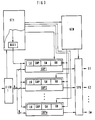
- FIG. 1 schematically shows an ATM network operating according to an asynchronous transfer principle ("asynchronous transfer mode"), which may have a plurality of inputs and a plurality of outputs.
- the inputs and outputs are each designed to receive or deliver message cells having a cell header and an information part with a fixed maximum transmission bit rate.
- a treatment device A is connected to at least a fixed number of inputs E1,... Em, which on the input side is connected to a feeder line ZL stands.
- This feeder line transmits message cells with a higher transmission bit rate than the transmission bit rate defined for the inputs and outputs.
- the number of inputs connected to the treatment device A corresponds to the bit rate ratio of the transmission bit rate defined for the feeder line to the transmission bit rate defined for the inputs and outputs of the ATM network, taking into account additional information to be transmitted within the ATM network to be explained.
- an evaluation device B is connected to at least a fixed number of outputs A1,..., Am, which may be assigned to the aforementioned inputs, and is connected on the output side to a customer line AL.
- This customer line is provided for the transmission of message cells which correspond to the previously mentioned message cells occurring on the feeder line ZL.
- the number of outputs again corresponds to the bit rate ratio of the transmission bit rate defined for the customer line to the transmission bit rate defined for these outputs, taking into account the additional information mentioned.
- the message cells occurring on the feeder line ZL which may be assigned to n different virtual connections, are first inserted into a "first-in-first-out" memory FIFO1 within the treatment device A.
- the message signals contained in message cells of a virtual connection are then divided into signal sections and inserted into newly formed message cells, which are assigned to a fixed virtual connection of the ATM network by a corresponding cell header and in one to be explained below, are distributed to the inputs E1 to Em of the ATM network.
- the number of bits of the signal sections mentioned are defined such that they can each be transmitted plus a defined number of information bits in the information part of a message cell.
- a message cell is shown schematically in FIG. 2.
- Such an example consists of 53 octets, the first five octets in a known manner forming a cell header which contains all the control signals required for the transmission of the respective message cell via the ATM network.
- the information part of the message cell consisting of 48 octets is connected to this cell header.
- m octets form the information bits already mentioned.
- the remaining octets i.e. (m - s) octets
- the remaining octets i.e. (m - s) octets
- the remaining octets on the other hand intended for the transmission of test information SNP for the signal section sequence number and a length identifier LK for octets occupied as useful octets in the information part.
- the (48 - m) octets of the information section are finally intended to accommodate a previously mentioned signal section.
- a separate repackaging device is assigned to each of the n virtual connections on the feeder line ZL.
- the n repackaging devices are labeled SUP1 to SUPn.
- the respective repackaging device receives message cells from the "first-in-first-out" memory FIFO1 in accordance with the order in which the individual message cells are written in, which are first depacketized. From the sequence of those contained in these The aforementioned signal sections are then formed for message signals. These are inserted one after the other in message cells of the respective virtual connection. In this case, a signal section sequence number which changes periodically and continuously from message cell to message cell, test information and a length indicator are entered in the information part of the respective message cell. The counting period for this signal section sequence number is determined in accordance with the maximum runtime of a message cell by the ATM network.
- the output lines of all repackaging devices (SUP1 to SUPn) are jointly fed to a transmission buffer device SPU, which cyclically distributes the message cells occurring on the output lines to the inputs E1 to Em of the ATM network.
- the transmission buffer device SPU transmits so-called empty cells to the possible inputs E1 to Em of the ATM network when transmission pauses occur on the output lines of the repackaging devices.
- the message cells fed to the inputs E1 to Em from the transmission buffer device SPU are transmitted to the outputs A1 to Am shown in FIG. 1 via defined transmission paths within the ATM network.
- the evaluation device B connected to the outputs A1 to Am of the ATM network and shown in FIG. 1 has as interface to these outputs a reception buffer device EPU which contains the different virtual connections supplied via the individual outputs forwards associated message cells to connection-specific repackaging devices.
- a reception buffer device EPU which contains the different virtual connections supplied via the individual outputs forwards associated message cells to connection-specific repackaging devices.
- EUP1 to EUPn corresponds to the repackaging devices.
- the repackaging devices are each connected to the receive buffer device EPU via a connecting line.
- the respective repackaging device depackages the message cells supplied via the associated connecting line and joins the signal sections contained therein to one another in accordance with the signal section sequence numbers.
- message signals are first formed by the respective depacking device, the number of bits of which is fixed in such a way that this corresponds to the number of bits that can be transmitted as useful signals in the information part of a message cell, i.e. that is, the message signals in the example given in FIG. 2 comprise 48 octets.
- the message signals are inserted one after the other into message cells of the respective virtual connection.
- These message cells are then fed to a "first-in-first-out" memory FIFO2, which forwards them to the customer line AL in the order of writing.
- the treatment device A indicated in FIG. 1 is shown in more detail in FIG. Thereafter, the "first-in-first-out" memory FIFO1 is connected via a control line or a control line bus to a control device ST1, which from this first-in-first-out "memory is the one in the cell header of a message cell currently present at its output contained connection information received Connection information is controlled under the control of a decoder DEC1 of the control device, the repackaging device (SUP1,..., SUPn) in question for the respective virtual connection in order to take over the respective message cell.
- the repackaging devices are connected on the one hand to the "first-in-first-out" memory FIFO1 and on the other hand to the decoder DEC1.
- the repackaging devices SUP1 to SUPn each contain a memory for accommodating message cells.
- four registers are provided in each of these repackaging devices.
- a signal section sequence number that changes continuously from message cell to message cell is entered into a first register, designated SN, by the respective repackaging device.
- a second register is provided for the recording of the associated test information.
- a third register, designated HR, is used to store a fixed cell header that is output by the control device ST1.
- this cell header can be identical to or differ from the cell header used on the feeder line ZL.
- a fourth of the above-mentioned registers which is denoted by LK in FIG. 3, finally serves to accommodate a length identifier already mentioned above.
- the supplied message cells are depacketized by the individual repackaging devices SUP1 to SUPn and the message signals contained therein successively in the associated memory entered.
- the above-mentioned signal sections are formed from these message signals, each of which is preceded by the information stored in the associated four registers in accordance with FIG. 2.
- a length identifier is generally used, which in the example assumed in FIG. 3 corresponds to the 48 m octets of the information part of a message cell.
- the formation of new message cells in the individual repackaging devices SUP1 to SUPn also takes place under the control of a control signal generator GEN, which for this purpose is connected to the repackaging devices via a control line or a control line bus.
- a control signal generator GEN which for this purpose is connected to the repackaging devices via a control line or a control line bus.
- the outputs of the repackaging devices SUP1 to SUPn are connected to inputs of the transmission buffer device SPU which, under the control of the control signal generator GEN, cyclically distributes the message cells supplied to them to the inputs E1 to Em of the ATM network.
- the receive buffer The EPU receives the message cells transmitted via the outputs A1 to Am of the ATM network. After checking the signal section sequence number contained in each of these, the message cells are forwarded to the connection-specific repackaging devices EUP1 to EUPn on the basis of the associated check information in accordance with the connection details contained in the cell headers of these message cells. This can be done, for example, by the reception buffer device EPU transmitting the connection details of the respective message cell to a control signal generator STGEN, which, in accordance with these connection details, transmits the relevant repackaging device via a control line or control bus arrangement common to all repackaging devices for receiving the releases the respective message cell.
- a control signal generator STGEN which, in accordance with these connection details, transmits the relevant repackaging device via a control line or control bus arrangement common to all repackaging devices for receiving the releases the respective message cell.
- the message cells are first unpackaged, the signal sections contained therein being entered in memory locations of a read / write memory RAM associated with the respective repackaging device.
- the associated signal section sequence number which is entered in a write address register AR in the respective repackaging device, is used as the memory address for the respective signal section.
- the length identifiers associated with the signal sections are also entered in the individual memory locations of the read-write memory RAM.
- the respective repackaging device (EUP1 to EUPn) turns the signal sections stored in the associated read / write memory RAM into consecutive ones, taking into account the length indicators stored with them Message signals are formed in the size specified above, which are inserted one after the other in message cells of the respective virtual connection.
- the cell header required for these message cells is stored in the respective repackaging device.
- the start address within the random access memory RAM for the formation of message signals to be inserted into a message cell is recorded in a read address register ARout of the respective repackaging device. This start address is updated every time a message cell is formed.
- the respective repackaging device In the presence of a message cell, which may be temporarily stored in an output register of the respective repackaging device, the respective repackaging device emits a message signal to a reading controller LS of a control device ST2. In response to such a signal, a decoder DEC2 connected to the read control LS controls the respective repackaging device for the delivery of the message cell currently present.
- the outputs of the repackaging devices EUP1 to EUPn are connected to inputs of a multiplexer Mux, which is also controlled by the decoder DEC2 and via which the individual message cells delivered are fed to the "first-in-first-out" memory FIFO2. From here, the message cells are then forwarded to the customer line AL, taking into account the order in which these message cells are written.
Abstract
Description
Die Erfindung betrifft ein Verfahren und eine Schaltungsanordnung gemäß Oberbegriff des Patentanspruches 1 bzw. des Patentanspruches 3.The invention relates to a method and a circuit arrangement according to the preamble of
Es ist bereits ein Verfahren zum Weiterleiten von auf Zubringerleitungen im Zuge von virtuellen Verbindungen nach einem asynchronen Übertragungsverfahren übertragenen Nachrichtenzellen, die jeweils einen die jeweilige virtuelle Verbindung bezeichnenden Zellenkopf aufweisen, über eine wenigstens zwei redundante Koppelvielfache aufweisende Zellenvermittlungseinrichtung zu mit dieser verbundenen Abnehmerleitungen hin bekannt (europäische Patentanmeldung 89 10 3798). Bei diesem bekannten Verfahren wird für jede der auf einer der Zubringerleitungen im Zuge einer virtuellen Verbindung übertragenen Nachrichtenzellen durch Vermehrfachen eine Nachrichtenzellen-Gruppe mit einer der Anzahl der redundanten Koppelvielfache entsprechenden Anzahl von identischen Nachrichtenzellen gebildet. In den Zellenkopf jeder der Nachrichtenzellen einer Nachrichtenzellen-Gruppe wird dabei eine identische, für aufeinanderfolgende Nachrichtenzellen-Gruppen sich ändernde Zusatzkennung in Form einer fortlaufend vergebenen Nachrichtenzellen-Folgenummer eingetragen. Anschließend werden die Nachrichtenzellen einer Nachrichtenzellen-Gruppe getrennt über die redundanten Koppelvielfache in Richtung zu der für die jeweilige virtuelle Verbindung in Frage kommenden Abnehmerleitung hin übertragen. Nach einer solchen Übertragung über die redundanten Koppelvielfache wird schließlich anhand der den Nachrichtenzellen jeweils beigefügten Zusatzkennung lediglich eine der zu einer Nachrichtenzellen-Gruppe gehörenden Nachrichtenzellen an die in Frage kommende Abnehmerleitung weitergeleitet.A method is already known for forwarding message cells transmitted to feeder lines in the course of virtual connections according to an asynchronous transmission method, each of which has a cell header denoting the respective virtual connection, via a cell switching device having at least two redundant switching multiples to customer lines connected to it (European Patent application 89 10 3798). In this known method, for each of the message cells transmitted on one of the feeder lines in the course of a virtual connection, a message cell group with a number of identical message cells corresponding to the number of redundant switching multiples is formed by multiplying. An identical additional identifier, which changes for successive message cell groups, is entered in the cell header of each of the message cells of a message cell group in the form of a continuously assigned message cell sequence number. The message cells of a message cell group are then transmitted separately via the redundant switching matrixes in the direction of the customer line that is suitable for the respective virtual connection. After such a transmission via the redundant switching multiples, only one of the message cells belonging to a message cell group is finally forwarded to the customer line in question on the basis of the additional identifier attached to the message cells.
Darüber hinaus ist bereits ein Verfahren zur Vermittlung von Nachrichtenzellen eines einen Nachrichtenzellenstrom nach einem asynchronen Übertragungsverfahren transportierenden Übertragungssystems über ein mit Moduln aufgebautes Koppelfeld vorgeschlagen worden (europäische Patentanmeldung 91 10 7434). Die Transportbitrate des Übertragungssystems beträgt ein Mehrfaches der Übertragungsbitrate der Koppelelemente der Module. Zu vermittelnde Nachrichtenzellen werden dabei auf eine dem Mehrfachen entsprechende Anzahl von Koppelfeldeingängen jeweils unter Hinzufügen von Informationen verteilt. Diese Informationen bezeichnen alle diejenige Module, über die die jeweiligen Nachrichtenzellen zu einem Ausgang des Koppelfeldes durchgeschaltet werden sollen. Die zu verschiedenen Ausgängen übertragenen Nachrichtenzellen werden dann wieder zu einem Nachrichtenzellenstrom zusammengefaßt. Dabei ist u.a. vorgesehen, daß den Nachrichtenzellen vor der Durchschaltung durch das Koppelfeld verbindungsindividuell eine zyklisch fortlaufende Folgenummer hinzugefügt wird, anhand der bei der Zusammenfassung zu dem Nachrichtenzellenstrom die Reihenfolge der Nachrichtenzellen für jede Verbindung sichergestellt wird, und daß die Nachrichtenzellen auf die Koppelfeldeingänge zyklisch verteilt werden.In addition, a method for switching message cells of a transmission system transporting a message cell stream according to an asynchronous transmission method via a switching matrix constructed with modules has already been proposed (European patent application 91 10 7434). The transport bit rate of the transmission system is a multiple of the transmission bit rate of the coupling elements of the modules. Message cells to be switched are distributed over a number of switching matrix inputs corresponding to the multiple, each with the addition of information. This information designates all those modules via which the respective message cells are to be switched through to an output of the switching matrix. The message cells transmitted to different outputs are then combined again to form a message cell stream. Among other things, It is provided that a cyclically consecutive sequence number is added to the message cells before connection through the switching matrix, on the basis of which the sequence of the message cells for each connection is ensured when the message cell stream is combined, and that the message cells are distributed cyclically to the switching matrix inputs.
Es ist nun Aufgabe der vorliegenden Erfindung, einen Weg zu zeigen, wie ein Verfahren und eine Schaltungsanordnung der eingangs genannten Art ausgebildet werden können, um mit einer ersten Übertragungsbitrate auftretende Nachrichtenzellen innerhalb eines ATM-Netzes übertragen zu können, welches für eine gegenüber der ersten Übertragungsbitrate niedrigere Übertragungsbitrate ausgelegt ist.It is an object of the present invention to show a way in which a method and a circuit arrangement of the type mentioned at the outset can be designed in order to be able to transmit message cells occurring within a ATM network with a first transmission bit rate, which is for a compared to the first transmission bit rate lower transmission bit rate is designed.
Gelöst wird diese Aufgabe durch die im Patentanspruch 1 angegebenen Verfahrensmerkmale bzw. durch die im Patentanspruch 3 angegebenen schaltungstechnischen Merkmale.This object is achieved by the method features specified in
Das Verfahren gemäß der vorliegenden Erfindung bringt dabei den Vorteil mit sich, daß Nachrichtenzellen zunächst depaketiert und die in diesen enthaltenen Nachrichtensignale signalabschnittweise in den Informationsteilen von neu gebildeten Nachrichtenzellen über eine Mehrzahl von Eingängen des ATM-Netzes übertragen werden und dabei für die Rückgewinnung der ursprünglichen Nachrichtenzellen erforderliche Zusatzinformationen in Form von Signalabschnitt-Folgenummern ausschließlich in den Informationsteilen der neu gebildeten Nachrichtenzellen, d.h. in dem eigentlichen Benutzerfeld dieser Nachrichtenzellen, eingefügt werden. Damit weisen diese Nachrichtenzellen hinsichtlich ihres jeweiligen Zellenkopfes keine Modifizierungen gegenüber den Zellenköpfen der übrigen über das ATM-Netz übertragenen Nachrichtenzellen auf, wodurch für die Übertragung der ursprünglichen Nachrichtenzellen innerhalb des ATM-Netzes kein zusätzlicher Steuerungsaufwand erforderlich ist. Vielmehr erfolgt nach einer Übertragung der Signalabschnitte enthaltenden Nachrichtenzellen eine Rückgewinnung von Nachrichtenzellen, die sowohl vom Inhalt als auch von der Reihenfolge her den ursprünglichen Nachrichtenzellen entsprechen, ausschließlich auf Benutzerebene, indem die in den Informationsfeldern der neu gebildeten Nachrichtenzellen übertragenen Signalabschnitt-Folgenummern ausgewertet werden.The method according to the present invention has the advantage that message cells are first depacketized and the message signals contained therein are transmitted in sections in the information parts of newly formed message cells via a plurality of inputs of the ATM network and thereby for the recovery of the original message cells required additional information in the form of signal section sequence numbers only in the information parts of the newly formed message cells, ie in the actual user field of these message cells. As a result, these message cells have no modifications to the cell headers of the other message cells transmitted via the ATM network, so that no additional control effort is required for the transmission of the original message cells within the ATM network. Rather, after a transmission of the message cells containing signal sections, message cells that correspond to the original message cells both in terms of content and in terms of sequence take place exclusively at the user level by evaluating the signal section sequence numbers transmitted in the information fields of the newly formed message cells.
Eine vorteilhafte Ausgestaltung des Verfahrens gemäß der vorliegenden Erfindung ergibt sich aus dem Patentanspruch 2. Der Vorteil dieser Ausgestaltung besteht dabei darin, daß es anhand von den Signalabschnitt-Folgenummern beigefügten Prüfinformationen und Längenkennzeichen in einfacher Weise möglich ist, Übertragungsfehler innerhalb des ATM-Netzes und die Länge des jeweiligen Signalabschnittes feststellen zu können.An advantageous embodiment of the method according to the present invention results from
Die vorstehend genannte Aufgabe wird bei einer Schaltungsanordnung der eingangs genannten Art durch die im Patentanspruch 3 angegebenen schaltungstechnischen Merkmale gelöst. Der Vorteil dieser Schaltungsanordnung besteht dabei in dem relativ geringen schaltungstechnischen Aufwand für die Übertragung von Nachrichtenzellen über ein für eine niedrigere Übertragungsbitrate ausgelegtes ATM-Netz und für die folgerichtige Rückgewinnung von Nachrichtenzellen unter Berücksichtigung von unterschiedlichen Laufzeiten von Nachrichtenzellen innerhalb des ATM-Netzes.The above object is achieved in a circuit arrangement of the type mentioned by the circuitry features specified in claim 3. The advantage of this circuit arrangement is the relatively low outlay in terms of circuitry for the transmission of message cells via an ATM network designed for a lower transmission bit rate and for the consequent recovery of message cells, taking into account different transit times of message cells within the ATM network.
Im folgenden wird die vorliegende Erfindung anhand von Zeichnungen beispielsweise näher erläutert.
Figur 1 zeigt in einer schematischen Darstellung ein ATM-Netz, bei dem die Erfindung angewandt ist,Figur 2 zeigt ein Diagramm, auf welches im folgenden noch näher eingegangen wird,- Figur 3 zeigt einen möglichen Aufbau einer der in
Figur 1 lediglich schematisch dargestellten sendeseitigen Umpaketiereinrichtungen und - Figur 4 zeigt den möglichen Aufbau einer der in
Figur 1 lediglich schematisch dargestellten empfangsseitigen Umpaketiereinrichtungen.
- FIG. 1 shows a schematic representation of an ATM network to which the invention is applied,
- FIG. 2 shows a diagram, which will be discussed in more detail below,
- FIG. 3 shows a possible structure of one of the repackaging devices and shown in FIG
- FIG. 4 shows the possible structure of one of the repacking devices on the receiving side, which is shown only schematically in FIG.
In Figur 1 ist ein nach einem asynchronen Übertragungsprinzip ("asynchronous transfer mode") arbeitendes ATM-Netz schematisch dargestellt, welches eine Mehrzahl von Eingängen sowie eine Mehrzahl von Ausgängen aufweisen möge. Die Eingänge und Ausgänge sind dabei jeweils für die Aufnahme bzw. Abgabe von einen Zellenkopf und einen Informationsteil aufweisenden Nachrichtenzellen mit einer festgelegten maximalen Übertragungsbitrate ausgelegt. An wenigstens eine festgelegte Anzahl von Eingängen E1,..., Em ist eine Behandlungseinrichtung A angeschlossen, die eingangsseitig mit einer Zubringerleitung ZL in Verbindung steht. Über diese Zubringerleitung erfolgt eine Übertragung von Nachrichtenzellen mit einer gegenüber der für die Eingänge und Ausgänge festgelegten Übertragungsbitrate höheren Übertragungsbitrate. Die Anzahl der mit der Behandlungseinrichtung A verbundenen Eingänge entspricht dabei dem Bitratenverhältnis der für die Zubringerleitung festgelegten Übertragungsbitrate zu der für die Eingänge und Ausgänge des ATM-Netzes festgelegten Übertragungsbitrate unter Berücksichtigung von noch zu erläuternden, innerhalb des ATM-Netzes zu übertragenden Zusatzinformationen.FIG. 1 schematically shows an ATM network operating according to an asynchronous transfer principle ("asynchronous transfer mode"), which may have a plurality of inputs and a plurality of outputs. The inputs and outputs are each designed to receive or deliver message cells having a cell header and an information part with a fixed maximum transmission bit rate. A treatment device A is connected to at least a fixed number of inputs E1,... Em, which on the input side is connected to a feeder line ZL stands. This feeder line transmits message cells with a higher transmission bit rate than the transmission bit rate defined for the inputs and outputs. The number of inputs connected to the treatment device A corresponds to the bit rate ratio of the transmission bit rate defined for the feeder line to the transmission bit rate defined for the inputs and outputs of the ATM network, taking into account additional information to be transmitted within the ATM network to be explained.
Darüber hinaus ist an wenigstens eine festgelegte Anzahl von Ausgängen A1,...,Am, die den zuvor erwähnten Eingängen zugeordnet sein mögen, eine Auswerteeinrichtung B angeschlossen, die ausgangsseitig mit einer Abnehmerleitung AL verbunden ist. Diese Abnehmerleitung ist für die Übertragung von Nachrichtenzellen vorgesehen, die den zuvor erwähnten, auf der Zubringerleitung ZL auftretenden Nachrichtenzellen entsprechen. Die Anzahl der Ausgänge entspricht dabei wieder dem Bitratenverhältnis der für die Abnehmerleitung festgelegten Übertragungsbitrate zu der für diese Ausgänge festgelegten Übertragungsbitrate unter Berücksichtigung der genannten Zusatzinformationen.In addition, an evaluation device B is connected to at least a fixed number of outputs A1,..., Am, which may be assigned to the aforementioned inputs, and is connected on the output side to a customer line AL. This customer line is provided for the transmission of message cells which correspond to the previously mentioned message cells occurring on the feeder line ZL. The number of outputs again corresponds to the bit rate ratio of the transmission bit rate defined for the customer line to the transmission bit rate defined for these outputs, taking into account the additional information mentioned.
Die auf der Zubringerleitung ZL auftretenden Nachrichtenzellen, die n unterschiedlichen virtuellen Verbindungen zugeordnet sein mögen, werden innerhalb der Behandlungseinrichtung A zunächst in einen "First-In-First-Out"-Speichers FIFO1 eingefügt. Die in Nachrichtenzellen einer virtuellen Verbindung enthaltenden Nachrichtensignale werden anschließend in Signalabschnitte unterteilt und in neu gebildete Nachrichtenzellen eingefügt, die durch einen entsprechenden Zellenkopf einer festgelegten virtuellen Verbindung des ATM-Netzes zugeordnet sind und in einer nachfolgend noch zu erläuternder Weise auf die genannten Eingänge E1 bis Em des ATM-Netzes verteilt werden.The message cells occurring on the feeder line ZL, which may be assigned to n different virtual connections, are first inserted into a "first-in-first-out" memory FIFO1 within the treatment device A. The message signals contained in message cells of a virtual connection are then divided into signal sections and inserted into newly formed message cells, which are assigned to a fixed virtual connection of the ATM network by a corresponding cell header and in one to be explained below, are distributed to the inputs E1 to Em of the ATM network.
Die genannten Signalabschnitte sind dabei hinsichtlich ihrer Bitanzahl so festgelegt, daß diese jeweils zuzüglich einer festgelegten Anzahl von Informationsbits in dem Informationsteil einer Nachrichtenzelle übertragbar sind. Eine solche Nachrichtenzelle ist in FIG 2 schematisch dargestellt. Danach besteht eine solche beispielsweise aus 53 Oktetts, wobei die ersten fünf Oktetts in bekannter Weise einen Zellenkopf ("Header") bilden, welcher sämtliche für die Übertragung der jeweiligen Nachrichtenzelle über das ATM-Netz erforderlichen Steuersignale enthält. An diesen Zellenkopf schließt sich der aus 48 Oktetts bestehende Informationsteil der Nachrichtenzelle an. m Oktetts bilden dabei die bereits erwähnten Informationsbits. s dieser m Oktetts sind bei dem Ausführungsbeispiel für die Übertragung einer noch zu erläuternden Signalabschnitt-Folgenummer SN, die verbleibenden Oktetts, d.h. (m - s) Oktetts, dagegen für die Übertragung einer Prüfinformation SNP für die Signalabschnitt-Folgenummer sowie eines Längekennzeichens LK für in dem Informationsteil als Nutzoktetts belegte Oktetts vorgesehen. Die (48 - m) Oktetts des Informationsteiles sind schließlich für die Aufnahme eines zuvor erwähnten Signalabschnittes vorgesehen.The number of bits of the signal sections mentioned are defined such that they can each be transmitted plus a defined number of information bits in the information part of a message cell. Such a message cell is shown schematically in FIG. 2. According to this, such an example consists of 53 octets, the first five octets in a known manner forming a cell header which contains all the control signals required for the transmission of the respective message cell via the ATM network. The information part of the message cell consisting of 48 octets is connected to this cell header. m octets form the information bits already mentioned. s of these m octets in the exemplary embodiment for the transmission of a signal section sequence number SN to be explained, the remaining octets, i.e. (m - s) octets, on the other hand intended for the transmission of test information SNP for the signal section sequence number and a length identifier LK for octets occupied as useful octets in the information part. The (48 - m) octets of the information section are finally intended to accommodate a previously mentioned signal section.
Für die Bildung von neuen Nachrichtenzellen ist jeder der n virtuellen Verbindungen auf der Zubringerleitung ZL eine gesonderte Umpaketiereinrichtung zugeordnet. In FIG 1 sind die n Umpaketiereinrichtungen mit SUP1 bis SUPn bezeichnet. Die jeweilige Umpaketiereinrichtung erhält dabei von dem "First-In-First-Out"-Speicher FIFO1 her nach Maßgabe der Einschreibreihenfolge der einzelnen Nachrichtenzellen nacheinander Nachrichtenzellen zugeführt, die zunächst depaketiert werden. Aus der Folge der in diesen enthaltenen Nachrichtensignale werden anschließend die genannten Signalabschnitte gebildet. Diese werden nacheinander in Nachrichtenzellen der jeweiligen virtuellen Verbindung eingefügt. Dabei sind in den Informationsteil der jeweiligen Nachrichtenzelle eine von Nachrichtenzelle zu Nachrichtenzelle sich periodisch fortlaufend verändernde Signalabschnitt-Folgenummer, eine Prüfinformation sowie ein Längenkennzeichen eingetragen. Die Zählperiode für diese Signalabschnitt-Folgenummer ist entsprechend der maximalen Laufzeit einer Nachrichtenzelle durch das ATM-Netz festgelegt.For the formation of new message cells, a separate repackaging device is assigned to each of the n virtual connections on the feeder line ZL. In FIG 1, the n repackaging devices are labeled SUP1 to SUPn. The respective repackaging device receives message cells from the "first-in-first-out" memory FIFO1 in accordance with the order in which the individual message cells are written in, which are first depacketized. From the sequence of those contained in these The aforementioned signal sections are then formed for message signals. These are inserted one after the other in message cells of the respective virtual connection. In this case, a signal section sequence number which changes periodically and continuously from message cell to message cell, test information and a length indicator are entered in the information part of the respective message cell. The counting period for this signal section sequence number is determined in accordance with the maximum runtime of a message cell by the ATM network.
Die Ausgangsleitungen sämtlicher Umpaketiereinrichtungen (SUP1 bis SUPn) sind gemeinsam einer Sende-Puffereinrichtung SPU zugeführt, welche die auf den Ausgangsleitungen auftretenden Nachrichtenzellen an die Eingänge E1 bis Em des ATM-Netzes zyklisch verteilt.The output lines of all repackaging devices (SUP1 to SUPn) are jointly fed to a transmission buffer device SPU, which cyclically distributes the message cells occurring on the output lines to the inputs E1 to Em of the ATM network.
Darüber hinaus werden durch die Sende-Puffereinrichtung SPU bei Auftreten von Übertragungspausen auf den Ausgangsleitungen der Umpaketiereinrichtungen sogenannte Leerzellen zu den in Frage kommenden Eingängen E1 bis Em des ATM-Netzes hin übertragen.In addition, the transmission buffer device SPU transmits so-called empty cells to the possible inputs E1 to Em of the ATM network when transmission pauses occur on the output lines of the repackaging devices.
Die den Eingängen E1 bis Em von der Sende-Puffereinrichtung SPU her zugeführten Nachrichtenzellen werden über festgelegte Übertragungswege innerhalb des ATM-Netzes zu den in Figur 1 dargestellten Ausgängen A1 bis Am übertragen.The message cells fed to the inputs E1 to Em from the transmission buffer device SPU are transmitted to the outputs A1 to Am shown in FIG. 1 via defined transmission paths within the ATM network.
Die mit den Ausgängen A1 bis Am des ATM-Netzes verbundene, in Figur 1 dargestellte Auswerteeinrichtung B weist als Schnittstelle zu diesen Ausgängen eine Empfangs-Puffer-Einrichtung EPU auf, welche die über die einzelnen Ausgänge zugeführten, unterschiedlichen virtuellen Verbindungen zugehörigen Nachrichtenzellen an verbindungsindividuelle Umpaketiereinrichtungen weiterleitet. Entsprechend den n unterschiedlichen virtuellen Verbindungen sind diese in Figur 1 mit EUP1 bis EUPn bezeichnet. Für dieses Weiterleiten sind die Umpaketiereinrichtungen jeweils über eine Anschlußleitung mit der Empfangs-Puffereinrichtung EPU verbunden.The evaluation device B connected to the outputs A1 to Am of the ATM network and shown in FIG. 1 has as interface to these outputs a reception buffer device EPU which contains the different virtual connections supplied via the individual outputs forwards associated message cells to connection-specific repackaging devices. Corresponding to the n different virtual connections, these are designated by EUP1 to EUPn in FIG. For this forwarding, the repackaging devices are each connected to the receive buffer device EPU via a connecting line.
Die jeweilige Umpaketiereinrichtung depaketiert die über die zugehörige Anschlußleitung zugeführten Nachrichtenzellen und fügt die in diesen enthaltenen Signalabschnitte entsprechend der Signalabschnitt-Folgenummern aneinander.The respective repackaging device depackages the message cells supplied via the associated connecting line and joins the signal sections contained therein to one another in accordance with the signal section sequence numbers.
Aus der Folge der aneinandergefügten Signalabschnitte werden durch die jeweilige Depaketiereinrichtung zunächst Nachrichtensignale gebildet, deren Bitanzahl derart festgelegt ist, daß diese jeweils der Anzahl der in dem Informationsteil einer Nachrichtenzelle als Nutzsignale übertragbaren Bits entspricht, d.h. also, daß die Nachrichtensignale bei dem in Figur 2 angegebenen Beispiel 48 Oktetts umfassen. Die Nachrichtensignale werden nacheinander in Nachrichtenzellen der jeweiligen virtuellen Verbindung eingefügt. Diese Nachrichtenzellen sind anschließend einem "First-In-First-Out"-Speicher FIFO2 zugeführt, der diese in der Reihenfolge des Einschreibens an die Abnehmerleitung AL weiterleitet.From the sequence of signal sections joined together, message signals are first formed by the respective depacking device, the number of bits of which is fixed in such a way that this corresponds to the number of bits that can be transmitted as useful signals in the information part of a message cell, i.e. that is, the message signals in the example given in FIG. 2 comprise 48 octets. The message signals are inserted one after the other into message cells of the respective virtual connection. These message cells are then fed to a "first-in-first-out" memory FIFO2, which forwards them to the customer line AL in the order of writing.
In Figur 3 ist die in Figur 1 angegebene Behandlungseinrichtung A detaillierter dargestellt. Danach ist der "First-In-First-Out"-Speicher FIFO1 über eine Steuerleitung oder einen Steuerleitungsbus mit einer Steuereinrichtung ST1 verbunden, welche von diesem First-In-First-Out"-Speicher die im Zellenkopf einer an dessen Ausgang gerade vorliegenden Nachrichtenzelle enthaltenen Verbindungsangaben zugeführt erhält. Nach Maßgabe dieser Verbindungsangaben wird unter der Steuerung eines Decodierers DEC1 der Steuereinrichtung die für die jeweilige virtuelle Verbindung in Frage kommende Umpaketiereinrichtung (SUP1,..., SUPn) angesteuert, um die jeweilige Nachrichtenzelle zu übernehmen. Die Umpaketiereinrichtungen sind dafür gemeinsam einerseits mit dem "First-In-First-Out"-Speicher FIFO1 und andererseits mit dem Decodierer DEC1 verbunden.The treatment device A indicated in FIG. 1 is shown in more detail in FIG. Thereafter, the "first-in-first-out" memory FIFO1 is connected via a control line or a control line bus to a control device ST1, which from this first-in-first-out "memory is the one in the cell header of a message cell currently present at its output contained connection information received Connection information is controlled under the control of a decoder DEC1 of the control device, the repackaging device (SUP1,..., SUPn) in question for the respective virtual connection in order to take over the respective message cell. For this purpose, the repackaging devices are connected on the one hand to the "first-in-first-out" memory FIFO1 and on the other hand to the decoder DEC1.
Für die Aufnahme von Nachrichtenzellen enthalten die Umpaketiereinrichtungen SUP1 bis SUPn jeweils einen Speicher. Darüber hinaus sind in diesen Umpaketiereinrichtungen jeweils vier Register vorgesehen. In ein erstes, mit SN bezeichnetes Register wird von der jeweiligen Umpaketiereinrichtung eine von Nachrichtenzelle zu Nachrichtenzelle sich fortlaufend verändernde Signalabschnitt-Folgenummer eingetragen. Ein zweites Register ist für die Aufnahme der zugehörigen Prüfinformation vorgesehen. Ein drittes, mit HR bezeichnetes Register dient für die Speicherung eines festgelegten, von der Steuereinrichtung ST1 her abgegebenen Zellenkopfes. Dieser Zellenkopf kann dabei je nach den Erfordernissen des ATM-Netzes identisch mit dem auf der Zubringerleitung ZL benutzten Zellenkopf sein bzw. von diesem abweichen. Für die Übernahme des von den einzelnen Umpaketiereinrichtungen zu benutzenden neuen Zellenkopfes sind diese jeweils über eine gesonderte Steuerleitung bzw. über einen gesonderten Steuerleitungsbus mit der Steuereinrichtung ST1 verbunden. Ein viertes der genannten Register, welches in Figur 3 mit LK bezeichnet ist, dient schließlich für die Aufnahme eines bereits oben erwähnten Längenkennzeichens.The repackaging devices SUP1 to SUPn each contain a memory for accommodating message cells. In addition, four registers are provided in each of these repackaging devices. A signal section sequence number that changes continuously from message cell to message cell is entered into a first register, designated SN, by the respective repackaging device. A second register is provided for the recording of the associated test information. A third register, designated HR, is used to store a fixed cell header that is output by the control device ST1. Depending on the requirements of the ATM network, this cell header can be identical to or differ from the cell header used on the feeder line ZL. To take over the new cell head to be used by the individual repackaging devices, these are each connected to the control device ST1 via a separate control line or via a separate control line bus. A fourth of the above-mentioned registers, which is denoted by LK in FIG. 3, finally serves to accommodate a length identifier already mentioned above.
Von den einzelnen Umpaketiereinrichtungen SUP1 bis SUPn werden die zugeführten Nachrichtenzellen depaketiert und die darin enthaltenen Nachrichtensignale nacheinander in den zugehörigen Speicher eingetragen . Aus diesen Nachrichtensignalen werden die oben erwähnten Signalabschnitte gebildet, denen jeweils die in den zugehörigen vier Registern gespeicherten Informationen entsprechend der Figur 2 vorangestellt werden. Für unmittelbar aufeinanderfolgende Signalabschnitte und damit neue Nachrichtenzellen wird dabei im Regelfalle ein Längenkennzeichen benutzt, welches bei dem in Figur 3 angenommenen Beispiel den 48 - m Oktetts des Informationsteiles einer Nachrichtenzelle entspricht. Es kann jedoch auch der Fall eintreten, daß durch Übertragungspausen im Zuge der jeweiligen virtuellen Verbindung auf der Zubringerleitung ZL für eine bestimmte Zeit lediglich Teile eines Signalabschnittes in dem zugehörigen Speicher gespeichert sind. Liegt dieser Zustand für eine festgelegte Zeit vor, so werden die vorliegenden Teile eines Signalabschnittes in eine Nachrichtenzelle eingefügt, wobei die dafür erforderliche Anzahl von Oktetts in dem zugehörigen Informationsteil durch ein entsprechendes Längenkennzeichen angegeben ist.The supplied message cells are depacketized by the individual repackaging devices SUP1 to SUPn and the message signals contained therein successively in the associated memory entered. The above-mentioned signal sections are formed from these message signals, each of which is preceded by the information stored in the associated four registers in accordance with FIG. 2. For immediately successive signal sections and thus new message cells, a length identifier is generally used, which in the example assumed in FIG. 3 corresponds to the 48 m octets of the information part of a message cell. However, it can also happen that only parts of a signal section are stored in the associated memory for a certain time due to transmission pauses in the course of the respective virtual connection on the feeder line ZL. If this state exists for a fixed time, the parts of a signal section are inserted into a message cell, the number of octets required for this being indicated in the associated information part by a corresponding length identifier.
Die Bildung von neuen Nachrichtenzellen in den einzelnen Umpaketiereinrichtungen SUP1 bis SUPn erfolgt im übrigen unter der Steuerung eines Steuersignal-Generators GEN, der dafür über eine an eine Steuerleitung bzw. einen Steuerleitungsbus mit den Umpaketiereinrichtungen in Verbindung steht.The formation of new message cells in the individual repackaging devices SUP1 to SUPn also takes place under the control of a control signal generator GEN, which for this purpose is connected to the repackaging devices via a control line or a control line bus.
Die Ausgänge der Umpaketiereinrichtungen SUP1 bis SUPn sind mit Eingängen der Sende-Puffereinrichtung SPU verbunden, die unter der Steuerung des Steuersignal-Generators GEN die ihr zugeführten Nachrichtenzellen zyklisch auf die Eingänge E1 bis Em des ATM-Netzes verteilt.The outputs of the repackaging devices SUP1 to SUPn are connected to inputs of the transmission buffer device SPU which, under the control of the control signal generator GEN, cyclically distributes the message cells supplied to them to the inputs E1 to Em of the ATM network.
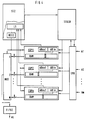
In Figur 4 ist die in Figur 1 angegebene Auswerteeinrichtung B detallierter dargestellt. Die Empfangs-Puffereinrichtung EPU erhält die über die Ausgänge A1 bis Am des ATM-Netzes übertragenen Nachrichtenzellen zugeführt. Diese Nachrichtenzellen werden nach einer Überprüfung der in diesen jeweils enthaltenen Signalabschnitt-Folgenummer anhand der zugehörigen Prüfinformation nach Maßgabe der in den Zellenköpfen dieser Nachrichtenzellen jeweils enthaltenen Verbindungsangaben an die verbindungsindividuellen Umpaketierteinrichtungen EUP1 bis EUPn weitergeleitet. Dies kann beispielsweise dadurch geschehen, daß die Empfangs-Puffereinrichtung EPU die Verbindungsangaben der jeweiligen Nachrichtenzelle zu einem Steuersignal-Generator STGEN hin überträgt, der nach Maßgabe dieser Verbindungsangaben die in Frage kommende Umpaketiereinrichtung über eine für sämtliche Umpaketiereinrichtungen gemeinsame Steuerleitung bzw. Steuerbusanordnung für die Aufnahme der jeweiligen Nachrichtenzelle freigibt.In Figure 4, the evaluation device B shown in Figure 1 is shown in more detail. The receive buffer The EPU receives the message cells transmitted via the outputs A1 to Am of the ATM network. After checking the signal section sequence number contained in each of these, the message cells are forwarded to the connection-specific repackaging devices EUP1 to EUPn on the basis of the associated check information in accordance with the connection details contained in the cell headers of these message cells. This can be done, for example, by the reception buffer device EPU transmitting the connection details of the respective message cell to a control signal generator STGEN, which, in accordance with these connection details, transmits the relevant repackaging device via a control line or control bus arrangement common to all repackaging devices for receiving the releases the respective message cell.
In den Umpaketiereinrichtungen erfolgt jeweils zunächst eine Depaketierung der Nachrichtenzellen, wobei die in diesen enthaltenen Signalabschnitte in Speicherplätze eines der jeweiligen Umpaketiereinrichtung zugehörigen Schreib-Lese-Speichers RAM eingetragen werden. Als Speicheradresse für den jeweiligen Signalabschnitt wird dabei die diesem zugehörige Signalabschnitt-Folgenummer benutzt, welche in ein Schreibadressen-Register ARin der jeweiligen Umpakektiereinrichtung eingetragen wird.In the repackaging devices, the message cells are first unpackaged, the signal sections contained therein being entered in memory locations of a read / write memory RAM associated with the respective repackaging device. The associated signal section sequence number, which is entered in a write address register AR in the respective repackaging device, is used as the memory address for the respective signal section.
Im übrigen werden in die einzelnen Speicherplätze des Schreib-Lese-Speichers RAM auch die den Signalabschnitten zugehörigen Längenkennzeichen eingetragen.In addition, the length identifiers associated with the signal sections are also entered in the individual memory locations of the read-write memory RAM.
Durch die jeweilige Umpaketiereinrichtung (EUP1 bis EUPn) werden aus den in dem zugehörigen Schreib-Lese-Speicher RAM gespeicherten Signalabschnitten unter Berücksichtigung der mit diesen gespeicherten Längenkennzeichen aufeinanderfolgende Nachrichtensignale in der oben angegebenen Größe gebildet, die nacheinander in Nachrichtenzellen der jeweiligen virtuellen Verbindung eingefügt werden. Der für diese Nachrichtenzellen erforderliche Zellenkopf ist dabei in der jeweiligen Umpaketiereinrichtung gespeichert. Darüber hinaus ist die Anfangsadresse innerhalb des Schreib-Lese-Speichers RAM für die Bildung von in eine Nachrichtenzelle gerade einzufügenden Nachrichtensignalen in einem Leseadressen-Register ARout der jeweiligen Umpaketiereinrichtung festgehalten. Diese Anfangsadresse wird mit jeder Bildung einer Nachrichtenzelle aktualisiert.The respective repackaging device (EUP1 to EUPn) turns the signal sections stored in the associated read / write memory RAM into consecutive ones, taking into account the length indicators stored with them Message signals are formed in the size specified above, which are inserted one after the other in message cells of the respective virtual connection. The cell header required for these message cells is stored in the respective repackaging device. In addition, the start address within the random access memory RAM for the formation of message signals to be inserted into a message cell is recorded in a read address register ARout of the respective repackaging device. This start address is updated every time a message cell is formed.
Bei Vorliegen einer Nachrichtenzelle, die beispielsweise in einem Ausgangsregister der jeweiligen Umpaketiereinrichtung zwischengespeichert sein möge, gibt die jeweilige Umpaketiereinrichtung ein Meldesignal an eine Lesesteuerung LS einer Steuereinrichtung ST2 ab. Auf ein solches Meldesignal hin steuert ein mit der Lesesteuerung LS verbundener Decodierer DEC2 die jeweilige Umpaketiereinrichtung für die Abgabe der gerade vorliegenden Nachrichtenzelle an. Die Ausgänge der Umpaketiereinrichtungen EUP1 bis EUPn sind dabei mit Eingängen eines Multiplexers Mux verbunden, der ebenfalls von dem Decodierer DEC2 gesteuert ist und über den die einzelnen abgegebenen Nachrichtenzellen dem "First-In-First-Out"-Speicher FIFO2 zugeführt sind. Von hier aus erfolgt dann eine Weiterleitung der Nachrichtenzellen an die Abnehmerleitung AL, und zwar unter Berücksichtigung der Einschreibreihenfolge dieser Nachrichtenzellen.In the presence of a message cell, which may be temporarily stored in an output register of the respective repackaging device, the respective repackaging device emits a message signal to a reading controller LS of a control device ST2. In response to such a signal, a decoder DEC2 connected to the read control LS controls the respective repackaging device for the delivery of the message cell currently present. The outputs of the repackaging devices EUP1 to EUPn are connected to inputs of a multiplexer Mux, which is also controlled by the decoder DEC2 and via which the individual message cells delivered are fed to the "first-in-first-out" memory FIFO2. From here, the message cells are then forwarded to the customer line AL, taking into account the order in which these message cells are written.
Claims (3)
dadurch gekennzeichnet,
daß die der jeweiligen virtuellen Verbindung zugehörigen Nachrichtenzellen depaketiert werden,
daß die in den Nachrichtenzellen enthaltenen Nachrichtensignale in aufeinanderfolgende Signalabschnitte unterteilt werden, deren jeweilige Bitanzahl derart einheitlich festgelegt ist, daß diese zuzüglich einer festgelegten Anzahl von Informationsbits der Anzahl der in dem Informationsteil einer Nachrichtenzelle als Nutzsignale übertragbaren Bits entspricht,
daß die Signalabschnitte nacheinander in die Informationsteile von Nachrichtenzellen eingefügt und in die Informationsteile als Informationsbits dabei eine sich fortlaufend verändernde Signalabschnitt-Folgenummer eingetragen wird, daß die Nachrichtenzellen nacheinander auf eine dem Bitratenverhältnis der ersten zur zweiten Übertragungsbitrate entsprechende Anzahl von Eingängen (E1 bis Em) des ATM-Netzes verteilt und über die betreffenden Eingänge zu diesen zugeordneten Ausgängen (A1 bis Am) des ATM-Netzes hin übertragen werden,
daß den an den betreffenden Ausgängen auftretenden Nachrichtenzellen der in diesen jeweils enthaltene Signalabschnitt sowie die diesem zugehörige Signalabschnitt-Folgenummer entnommen werden,
daß aus der Folge der Signalabschnitte für die jeweilige virtuelle Verbindung Nachrichtensignale gebildet werden, deren Bitanzahl derart festgelegt ist, daß diese jeweils der Anzahl der in dem Informationsteil einer Nachrichtenzelle als Nutzsignale übertragbaren Bits entspricht, und daß die Nachrichtensignale anschließend nacheinander in die jeweilige virtuelle Verbindung bezeichnende Nachrichtenzellen eingefügt werden, welche mit der ersten Übertragungsbitrate weitergeleitet werden.Method for transmitting message cells occurring in the course of at least one virtual connection with a first transmission bit rate, each of which is formed from a cell header with an identification of the respective virtual connection and an information part, via one and a plurality of inputs operating according to an asynchronous transfer mode (ATM) ATM network having outputs and having at least one ATM communication device, the inputs and outputs each being designed for receiving or delivering message cells with a second transmission bit rate lower than the first transmission bit rate,
characterized by
that the message cells belonging to the respective virtual connection are depacketized,
that the message signals contained in the message cells are divided into successive signal sections, the respective number of bits of which is defined in such a way that, plus a fixed number of information bits, this corresponds to the number of bits that can be transmitted as useful signals in the information part of a message cell,
that the signal sections are inserted one after the other into the information parts of message cells and a continuously changing signal section sequence number is entered as information bits in the information parts, that the message cells are successively connected to a number of inputs (E1 to Em) corresponding to the bit rate ratio of the first to the second transmission bit rate ATM network distributed and transmitted via the relevant inputs to these assigned outputs (A1 to Am) of the ATM network,
that the message cells occurring at the relevant outputs the signal section contained therein and the signal section sequence number associated therewith are taken,
that message signals are formed from the sequence of the signal sections for the respective virtual connection, the number of bits of which is determined such that this corresponds in each case to the number of bits which can be transmitted as useful signals in the information part of a message cell, and that the message signals subsequently designating the respective virtual connection Message cells are inserted, which are forwarded at the first transmission bit rate.
dadurch gekennzeichnet,
daß in die Informationsteile der Nachrichtenzellen jeweils als Informationsbits neben einer Signalabschnitt-Folgenummer eine für deren Überprüfung auf eine fehlerfreie Übertragung dienende Prüfinformation sowie ein Längenkennzeichen für die Länge des in dem jeweiligen Informationsteil enthaltenen Signalabschnittes eingetragen werden.Method according to claim 1,
characterized by
that in the information parts of the message cells each as information bits in addition to a signal section sequence number, test information used for checking them for error-free transmission and a length indicator for the length of the signal section contained in the respective information part are entered.
und welches über interne Eingänge (E1 bis EP) und Ausgänge (A1 bis AP) verfügt, welche für die Aufnahme bzw. Abgabe von Nachrichtensignalen in Form von einen Zellenkopf und einen Informationsteil enthaltenden Nachrichtenzellen mit einer gegenüber der ersten Übertragungsbitrate niedrigeren Übertragungsbitrate ausgelegt sind,
dadurch gekennzeichnet,
daß wenigstens eine Behandlungseinrichtung (A) vorgesehen ist, welche einerseits mit der jeweiligen Zubringerleitung (ZL) und andererseits mit einer dem Bitratenverhältnis der ersten zur zweiten Übertragungsbitrate entsprechenden Anzahl von internen Eingängen (E1 bis Em) des ATM-Netzes verbunden ist,
daß die jeweilige Behandlungseinrichtung über den virtuellen Verbindungen individuell zugeordnete Umpaketiereinrichtungen (SUP1,..., SUPn) verfügt, welchen jeweils die Nachrichtenzellen der zugehörigen virtuellen Verbindung zugeführt sind,
daß die jeweilige Umpaketiereinrichtung dabei die Nachrichtenzellen depaketiert und aus der Folge der in den zugehörigen Informationsteilen enthaltenen Nachrichtensignale Signalabschnitte bildet, die jeweils zusammen mit einer von Signalabschnitt zu Signalabschnitt sich ändernden Signalabschnitt-Folgenummer in den Informationsteil einer Nachrichtenzelle eingefügt und diese Nachrichtenzellen auf die betreffenden internen Eingänge (E1 bis Em) des ATM-Netzes in einer festgelegten Reihenfolge verteilt sind, daß wenigstens eine Auswerteeinrichtung (B) vorgesehen ist, welche einerseits mit der jeweiligen Abnehmerleitung (AL) und andererseits mit einer dem betreffenden Bitratenverhältnis entsprechenden, der genannten Anzahl von internen Eingängen zugeordneten Anzahl von internen Ausgängen (A1 bis Am) des ATM-Netzes verbunden ist,
daß die Auswerteeinrichtung (B) mit den betreffenden internen Ausgängen verbundene verbindungsindividuelle Umpaketiereinrichtungen (EUP1,..., EUPn) aufweist,
daß die jeweilige Umpaketiereinrichtung den über die internen Ausgänge (A1 bis Am) zugeführten Nachrichtenzellen der jeweiligen virtuellen Verbindung jeweils den darin enthaltenen Signalabschnitt sowie die Signalabschnitt-Folgenummer entnimmt und den jeweiligen Signalabschnitt zunächst in einen Schreib-/Lese-Speicher (RAM) unter einer der zugehörigen Signalabschnitt-Folgenummer entsprechenden Schreibadresse zwischenspeichert,
und daß durch die jeweilige Umpaketiereinrichtung (EUP1,..., EUPn) aus der Folge der in dem zugehörigen Schreib/-Lese-Speicher (RAM) gespeicherten Signalabschnitte Nachrichtensignale gebildet sind, welche in die Informationsteile von an die jeweilige Abnehmerleitung (AL) weitergeleitete Nachrichtenzellen der jeweiligen virtuellen Verbindung eingefügt sind.Circuit arrangement for performing the method according to claim 1 with an ATM network having at least one ATM communication device (KE), which can be transmitted with at least one feeder line (ZL) via the message cells of at least one virtual connection with a first transmission bit rate, and with at least one Customer line (AL) for the forwarding of message cells is connected to the first transmission bit rate
and which has internal inputs (E1 to EP) and outputs (A1 to AP) which are used for the reception or delivery of message signals in the form of a cell header and message cells containing an information part are designed with a transmission bit rate lower than the first transmission bit rate,
characterized by
that at least one treatment device (A) is provided, which is connected on the one hand to the respective feeder line (ZL) and on the other hand to a number of internal inputs (E1 to Em) of the ATM network which corresponds to the bit rate ratio of the first to the second transmission bit rate,
that the respective treatment device has repackaging devices (SUP1, ..., SUPn) individually assigned to the virtual connections, to which the message cells of the associated virtual connection are fed,
that the respective repackaging device depackets the message cells and forms signal sections from the sequence of the message signals contained in the associated information parts, each of which, together with a signal section sequence number changing from signal section to signal section, is inserted into the information part of a message cell and these message cells onto the relevant internal inputs (E1 to Em) of the ATM network are distributed in a fixed order that at least one evaluation device (B) is provided, which on the one hand with the respective customer line (AL) and on the other hand with a specified number of internal inputs corresponding to the relevant bit rate ratio assigned number of internal outputs (A1 to Am) of the ATM network,
that the evaluation device (B) has connection-specific repackaging devices (EUP1, ..., EUPn) connected to the relevant internal outputs,
that the respective repackaging device the message cells supplied via the internal outputs (A1 to Am) takes the signal section and the signal section sequence number from the respective virtual connection and temporarily stores the respective signal section in a read / write memory (RAM) under a write address corresponding to the associated signal section sequence number,
and that message packets are formed by the respective repackaging device (EUP1, ..., EUPn) from the sequence of the signal sections stored in the associated read / write memory (RAM), which relayed signals into the information parts from to the respective customer line (AL) Message cells of the respective virtual connection are inserted.
Priority Applications (5)
| Application Number | Priority Date | Filing Date | Title |
|---|---|---|---|
| AT92114798T ATE162034T1 (en) | 1992-08-28 | 1992-08-28 | METHOD AND CIRCUIT ARRANGEMENT FOR TRANSMITTING MESSAGE CELLS WITHIN AN ATM NETWORK |
| EP92114798A EP0584398B1 (en) | 1992-08-28 | 1992-08-28 | Method and circuit for transmitting information cells within an ATM network |
| DE59209115T DE59209115D1 (en) | 1992-08-28 | 1992-08-28 | Method and circuit arrangement for transmitting message cells within an ATM network |
| JP20505393A JPH06177907A (en) | 1992-08-28 | 1993-08-19 | Cell transmission method and circuit device |
| US08/111,000 US5394398A (en) | 1992-08-28 | 1993-08-24 | Method and circuit arrangement for the transmission of message cells within an ATM network |
Applications Claiming Priority (1)
| Application Number | Priority Date | Filing Date | Title |
|---|---|---|---|
| EP92114798A EP0584398B1 (en) | 1992-08-28 | 1992-08-28 | Method and circuit for transmitting information cells within an ATM network |
Publications (2)
| Publication Number | Publication Date |
|---|---|
| EP0584398A1 true EP0584398A1 (en) | 1994-03-02 |
| EP0584398B1 EP0584398B1 (en) | 1998-01-07 |
Family
ID=8209958
Family Applications (1)
| Application Number | Title | Priority Date | Filing Date |
|---|---|---|---|
| EP92114798A Expired - Lifetime EP0584398B1 (en) | 1992-08-28 | 1992-08-28 | Method and circuit for transmitting information cells within an ATM network |
Country Status (5)
| Country | Link |
|---|---|
| US (1) | US5394398A (en) |
| EP (1) | EP0584398B1 (en) |
| JP (1) | JPH06177907A (en) |
| AT (1) | ATE162034T1 (en) |
| DE (1) | DE59209115D1 (en) |
Cited By (1)
| Publication number | Priority date | Publication date | Assignee | Title |
|---|---|---|---|---|
| WO1998008355A1 (en) * | 1996-08-16 | 1998-02-26 | Northern Telecom Limited | Inverse multiplexing of digital data |
Families Citing this family (39)
| Publication number | Priority date | Publication date | Assignee | Title |
|---|---|---|---|---|
| DE4331579C2 (en) * | 1993-09-16 | 1995-07-06 | Siemens Ag | Method for transmitting message cells over redundant virtual path pairs of an ATM communication network |
| FI98773C (en) * | 1994-02-28 | 1997-08-11 | Nokia Telecommunications Oy | A method for sharing traffic in a telecommunications network implemented with ATM technology |
| JP3405800B2 (en) * | 1994-03-16 | 2003-05-12 | 富士通株式会社 | ATM-based variable-length cell transfer system, ATM-based variable-length cell switch, and ATM-based variable-length cell switch |
| US6023474A (en) * | 1996-11-22 | 2000-02-08 | Sprint Communications C.O.L.P. | Broadband telecommunications system interface |
| US6172977B1 (en) * | 1994-05-05 | 2001-01-09 | Sprint Communications Company, L. P. | ATM direct access line system |
| US6181703B1 (en) * | 1995-09-08 | 2001-01-30 | Sprint Communications Company L. P. | System for managing telecommunications |
| RU2138919C1 (en) | 1994-05-05 | 1999-09-27 | Спринт Комьюникейшнз Компани Л.П. | Method, system and device to control telephone communication |
| US6430195B1 (en) | 1994-05-05 | 2002-08-06 | Sprint Communications Company L.P. | Broadband telecommunications system interface |
| US6314103B1 (en) | 1994-05-05 | 2001-11-06 | Sprint Communications Company, L.P. | System and method for allocating bandwidth for a call |
| US5991301A (en) * | 1994-05-05 | 1999-11-23 | Sprint Communications Co. L.P. | Broadband telecommunications system |
| US5926482A (en) | 1994-05-05 | 1999-07-20 | Sprint Communications Co. L.P. | Telecommunications apparatus, system, and method with an enhanced signal transfer point |
| US5920562A (en) * | 1996-11-22 | 1999-07-06 | Sprint Communications Co. L.P. | Systems and methods for providing enhanced services for telecommunication call |
| US6031840A (en) * | 1995-12-07 | 2000-02-29 | Sprint Communications Co. L.P. | Telecommunications system |
| US6633561B2 (en) | 1994-05-05 | 2003-10-14 | Sprint Communications Company, L.P. | Method, system and apparatus for telecommunications control |
| FR2737371A1 (en) * | 1995-07-26 | 1997-01-31 | Trt Telecom Radio Electr | SECURITY BY DOUBLING AT LEAST CERTAIN LOGIC CHANNELS IN A TELECOMMUNICATIONS NETWORK |
| WO1997028622A1 (en) * | 1996-02-02 | 1997-08-07 | Sprint Communications Company, L.P. | Atm gateway system |
| US5826014A (en) * | 1996-02-06 | 1998-10-20 | Network Engineering Software | Firewall system for protecting network elements connected to a public network |
| US5898830A (en) * | 1996-10-17 | 1999-04-27 | Network Engineering Software | Firewall providing enhanced network security and user transparency |
| US5870550A (en) * | 1996-02-26 | 1999-02-09 | Network Engineering Software | Web server employing multi-homed, moldular framework |
| US8117298B1 (en) | 1996-02-26 | 2012-02-14 | Graphon Corporation | Multi-homed web server |
| US6018525A (en) * | 1996-03-11 | 2000-01-25 | Sprint Communications Company, L.P. | ATM transport of voice band signals with channel associated signaling |
| US5940393A (en) * | 1996-05-28 | 1999-08-17 | Sprint Communications Co. L.P. | Telecommunications system with a connection processing system |
| US6002689A (en) * | 1996-11-22 | 1999-12-14 | Sprint Communications Co. L.P. | System and method for interfacing a local communication device |
| CA2271926C (en) | 1996-11-22 | 2005-10-11 | Sprint Communications Company, L.P. | System and method for transporting a call in a telecommunication network |
| US6014378A (en) * | 1996-11-22 | 2000-01-11 | Sprint Communications Company, L.P. | Telecommunications tandem system for circuit-based traffic |
| US6115380A (en) * | 1996-11-22 | 2000-09-05 | Sprint Communications Co., L.P. | Broadband telecommunications system |
| US6067299A (en) * | 1997-04-16 | 2000-05-23 | Sprint Communications Company, L.P. | Communications system for providing ATM connections and echo cancellation |
| US6704327B1 (en) | 1997-05-09 | 2004-03-09 | Sprint Communications Company, L.P. | System and method for connecting a call |
| US6137800A (en) * | 1997-05-09 | 2000-10-24 | Sprint Communications Company, L. P. | System and method for connecting a call |
| US6178170B1 (en) | 1997-05-13 | 2001-01-23 | Sprint Communications Company, L. P. | System and method for transporting a call |
| CA2282441C (en) * | 1997-12-25 | 2004-07-27 | Kabushiki Kaisha Toshiba | Atm relay device and network including same |
| US6563918B1 (en) | 1998-02-20 | 2003-05-13 | Sprint Communications Company, LP | Telecommunications system architecture for connecting a call |
| US6470019B1 (en) | 1998-02-20 | 2002-10-22 | Sprint Communications Company L.P. | System and method for treating a call for call processing |
| US6483837B1 (en) | 1998-02-20 | 2002-11-19 | Sprint Communications Company L.P. | System and method for connecting a call with an interworking system |
| US6160871A (en) | 1998-04-10 | 2000-12-12 | Sprint Communications Company, L.P. | Communications test system |
| FI106504B (en) * | 1998-10-06 | 2001-02-15 | Nokia Networks Oy | Data segmentation method in a communication system |
| US6888833B1 (en) | 1998-12-22 | 2005-05-03 | Sprint Communications Company L.P. | System and method for processing call signaling |
| US6724765B1 (en) | 1998-12-22 | 2004-04-20 | Sprint Communications Company, L.P. | Telecommunication call processing and connection system architecture |
| US7965729B2 (en) * | 2001-05-23 | 2011-06-21 | Polytechnic University | Transferring data such as files |
Citations (3)
| Publication number | Priority date | Publication date | Assignee | Title |
|---|---|---|---|---|
| EP0355797A2 (en) * | 1988-08-26 | 1990-02-28 | Hitachi, Ltd. | Signalling apparatus for use in an ATM switching system |
| EP0471380A1 (en) * | 1990-08-17 | 1992-02-19 | Hitachi, Ltd. | ATM switch |
| EP0384936B1 (en) * | 1989-03-03 | 1994-06-15 | Siemens Aktiengesellschaft | Method and circuit arrangement for forwarding information packets from incoming links via a packet-switching device |
Family Cites Families (4)
| Publication number | Priority date | Publication date | Assignee | Title |
|---|---|---|---|---|
| WO1991002420A1 (en) * | 1989-08-09 | 1991-02-21 | Alcatel N.V. | Communication switching element and method for transmitting variable length cells |
| JP2907886B2 (en) * | 1989-09-14 | 1999-06-21 | 株式会社日立製作所 | Switching system |
| US5204882A (en) * | 1990-12-14 | 1993-04-20 | Bell Communications Research, Inc. | Service clock recovery for variable bit rate services |
| EP0512141A1 (en) * | 1991-05-07 | 1992-11-11 | Siemens Aktiengesellschaft | Procedure for switching high bit rate ATM data cell streams through a switching device with a lower bit rate |
-
1992
- 1992-08-28 EP EP92114798A patent/EP0584398B1/en not_active Expired - Lifetime
- 1992-08-28 DE DE59209115T patent/DE59209115D1/en not_active Expired - Fee Related
- 1992-08-28 AT AT92114798T patent/ATE162034T1/en not_active IP Right Cessation
-
1993
- 1993-08-19 JP JP20505393A patent/JPH06177907A/en not_active Withdrawn
- 1993-08-24 US US08/111,000 patent/US5394398A/en not_active Expired - Fee Related
Patent Citations (3)
| Publication number | Priority date | Publication date | Assignee | Title |
|---|---|---|---|---|
| EP0355797A2 (en) * | 1988-08-26 | 1990-02-28 | Hitachi, Ltd. | Signalling apparatus for use in an ATM switching system |
| EP0384936B1 (en) * | 1989-03-03 | 1994-06-15 | Siemens Aktiengesellschaft | Method and circuit arrangement for forwarding information packets from incoming links via a packet-switching device |
| EP0471380A1 (en) * | 1990-08-17 | 1992-02-19 | Hitachi, Ltd. | ATM switch |
Cited By (5)
| Publication number | Priority date | Publication date | Assignee | Title |
|---|---|---|---|---|
| WO1998008355A1 (en) * | 1996-08-16 | 1998-02-26 | Northern Telecom Limited | Inverse multiplexing of digital data |
| US6205142B1 (en) | 1996-08-16 | 2001-03-20 | Nortel Networks Limited | Inverse multiplexing of digital data |
| US6894977B1 (en) | 1996-08-16 | 2005-05-17 | Nortel Networks Limited | Inverse multiplexing of digital data |
| US7570595B2 (en) | 1996-08-16 | 2009-08-04 | Nortel Networks Limited | Inverse multiplexing of digital data |
| US8125912B2 (en) | 1996-08-16 | 2012-02-28 | Ericsson Ab | Inverse multiplexing of digital data |
Also Published As
| Publication number | Publication date |
|---|---|
| EP0584398B1 (en) | 1998-01-07 |
| ATE162034T1 (en) | 1998-01-15 |
| DE59209115D1 (en) | 1998-02-12 |
| US5394398A (en) | 1995-02-28 |
| JPH06177907A (en) | 1994-06-24 |
Similar Documents
| Publication | Publication Date | Title |
|---|---|---|
| EP0584398B1 (en) | Method and circuit for transmitting information cells within an ATM network | |
| EP0384936B1 (en) | Method and circuit arrangement for forwarding information packets from incoming links via a packet-switching device | |
| EP0453607B1 (en) | Method and circuit arrangement for reducing the loss of information packets transmitted through a packet switch | |
| EP0315919B1 (en) | Switching node for switching data signals carried in data packets | |
| EP0329005B1 (en) | Method for establishing virtual circuits via switches of a multistage switching arrangement | |
| EP0566961B1 (en) | Method and circuit to enforce the preassigned transmission rate in an ATM switching equipment | |
| EP0315918B1 (en) | Switching node for switching data signals carried in data packets | |
| EP0512141A1 (en) | Procedure for switching high bit rate ATM data cell streams through a switching device with a lower bit rate | |
| EP0453606B1 (en) | Method and circuit arrangement for reducing the loss of information packets transmitted through a packet switch | |
| EP0576856A2 (en) | Method and circuit for transmission of a continuous ATM bitstream | |
| DE2062236A1 (en) | Improvements to redundancy reduction systems and devices for use therein | |
| EP0503283A1 (en) | A two-stage, at least duplicated, folded ATM-self-routing arrangement with (2nx2n)-coupling multiples | |
| EP0685950A2 (en) | Local asynchronous transfer mode (ATM) network | |
| EP0442581B1 (en) | Asynchronous time division multiplex communication system | |
| EP0173274B1 (en) | Method and circuit arrangement for realizing and maintaining a time division broadband connection | |
| EP0685949A2 (en) | Packet transmission system | |
| EP0580999B1 (en) | Space and time switching element | |
| EP0454218B1 (en) | Time division multiplex transfer system | |
| EP0414950B1 (en) | Method of switching voice and/or data information distributively transmitted in several time slots | |
| EP0603424A1 (en) | Method and apparatus for transmission of communication cells over ATM-communications arrangement | |
| EP0443672A2 (en) | Asynchronous transfer mode system | |
| DE3210462A1 (en) | Circuit arrangement for transmission of data signal packets between subscriber stations and a packet switching exchange | |
| EP0584387B1 (en) | Method and circuit to monitor cell sequence during transmission of data cells | |
| EP0046259B1 (en) | Method of establishing connections from subscriber sets or transmission lines connected to a data exchange to signal converters | |
| EP0450725B1 (en) | Asynchronous time division multiplex system with a switching network |
Legal Events
| Date | Code | Title | Description |
|---|---|---|---|
| PUAI | Public reference made under article 153(3) epc to a published international application that has entered the european phase |
Free format text: ORIGINAL CODE: 0009012 |
|
| AK | Designated contracting states |
Kind code of ref document: A1 Designated state(s): AT BE CH DE FR GB IT LI NL SE |
|
| 17P | Request for examination filed |
Effective date: 19940322 |
|
| GRAG | Despatch of communication of intention to grant |
Free format text: ORIGINAL CODE: EPIDOS AGRA |
|
| 17Q | First examination report despatched |
Effective date: 19970327 |
|
| GRAG | Despatch of communication of intention to grant |
Free format text: ORIGINAL CODE: EPIDOS AGRA |
|
| GRAH | Despatch of communication of intention to grant a patent |
Free format text: ORIGINAL CODE: EPIDOS IGRA |
|
| GRAH | Despatch of communication of intention to grant a patent |
Free format text: ORIGINAL CODE: EPIDOS IGRA |
|
| GRAA | (expected) grant |
Free format text: ORIGINAL CODE: 0009210 |
|
| AK | Designated contracting states |
Kind code of ref document: B1 Designated state(s): AT BE CH DE FR GB IT LI NL SE |
|
| REF | Corresponds to: |
Ref document number: 162034 Country of ref document: AT Date of ref document: 19980115 Kind code of ref document: T |
|
| REG | Reference to a national code |
Ref country code: CH Ref legal event code: NV Representative=s name: SIEMENS SCHWEIZ AG Ref country code: CH Ref legal event code: EP |
|
| REF | Corresponds to: |
Ref document number: 59209115 Country of ref document: DE Date of ref document: 19980212 |
|
| ET | Fr: translation filed | ||
| ITF | It: translation for a ep patent filed |
Owner name: STUDIO JAUMANN P. & C. S.N.C. |
|
| GBT | Gb: translation of ep patent filed (gb section 77(6)(a)/1977) |
Effective date: 19980331 |
|
| PGFP | Annual fee paid to national office [announced via postgrant information from national office to epo] |
Ref country code: GB Payment date: 19980721 Year of fee payment: 7 |
|
| PGFP | Annual fee paid to national office [announced via postgrant information from national office to epo] |
Ref country code: AT Payment date: 19980729 Year of fee payment: 7 |
|
| PGFP | Annual fee paid to national office [announced via postgrant information from national office to epo] |
Ref country code: BE Payment date: 19980818 Year of fee payment: 7 |
|
| PGFP | Annual fee paid to national office [announced via postgrant information from national office to epo] |
Ref country code: SE Payment date: 19980819 Year of fee payment: 7 |
|
| PGFP | Annual fee paid to national office [announced via postgrant information from national office to epo] |
Ref country code: NL Payment date: 19980825 Year of fee payment: 7 |
|
| PGFP | Annual fee paid to national office [announced via postgrant information from national office to epo] |
Ref country code: FR Payment date: 19980826 Year of fee payment: 7 |
|
| PGFP | Annual fee paid to national office [announced via postgrant information from national office to epo] |
Ref country code: DE Payment date: 19981020 Year of fee payment: 7 |
|
| PLBE | No opposition filed within time limit |
Free format text: ORIGINAL CODE: 0009261 |
|
| STAA | Information on the status of an ep patent application or granted ep patent |
Free format text: STATUS: NO OPPOSITION FILED WITHIN TIME LIMIT |
|
| PGFP | Annual fee paid to national office [announced via postgrant information from national office to epo] |
Ref country code: CH Payment date: 19981116 Year of fee payment: 7 |
|
| 26N | No opposition filed | ||
| PG25 | Lapsed in a contracting state [announced via postgrant information from national office to epo] |
Ref country code: GB Free format text: LAPSE BECAUSE OF NON-PAYMENT OF DUE FEES Effective date: 19990828 Ref country code: AT Free format text: LAPSE BECAUSE OF NON-PAYMENT OF DUE FEES Effective date: 19990828 |
|
| PG25 | Lapsed in a contracting state [announced via postgrant information from national office to epo] |
Ref country code: SE Free format text: THE PATENT HAS BEEN ANNULLED BY A DECISION OF A NATIONAL AUTHORITY Effective date: 19990830 |
|
| PG25 | Lapsed in a contracting state [announced via postgrant information from national office to epo] |
Ref country code: LI Free format text: LAPSE BECAUSE OF NON-PAYMENT OF DUE FEES Effective date: 19990831 Ref country code: CH Free format text: LAPSE BECAUSE OF NON-PAYMENT OF DUE FEES Effective date: 19990831 Ref country code: BE Free format text: LAPSE BECAUSE OF NON-PAYMENT OF DUE FEES Effective date: 19990831 |
|
| BERE | Be: lapsed |
Owner name: SIEMENS A.G. Effective date: 19990831 |
|
| PG25 | Lapsed in a contracting state [announced via postgrant information from national office to epo] |
Ref country code: NL Free format text: LAPSE BECAUSE OF NON-PAYMENT OF DUE FEES Effective date: 20000301 |
|
| REG | Reference to a national code |
Ref country code: CH Ref legal event code: PL |
|
| GBPC | Gb: european patent ceased through non-payment of renewal fee |
Effective date: 19990828 |
|
| PG25 | Lapsed in a contracting state [announced via postgrant information from national office to epo] |
Ref country code: FR Free format text: LAPSE BECAUSE OF NON-PAYMENT OF DUE FEES Effective date: 20000428 |
|
| EUG | Se: european patent has lapsed |
Ref document number: 92114798.9 |
|
| NLV4 | Nl: lapsed or anulled due to non-payment of the annual fee |
Effective date: 20000301 |
|
| PG25 | Lapsed in a contracting state [announced via postgrant information from national office to epo] |
Ref country code: DE Free format text: LAPSE BECAUSE OF NON-PAYMENT OF DUE FEES Effective date: 20000601 |
|
| REG | Reference to a national code |
Ref country code: FR Ref legal event code: ST |
|
| PG25 | Lapsed in a contracting state [announced via postgrant information from national office to epo] |
Ref country code: IT Free format text: LAPSE BECAUSE OF NON-PAYMENT OF DUE FEES;WARNING: LAPSES OF ITALIAN PATENTS WITH EFFECTIVE DATE BEFORE 2007 MAY HAVE OCCURRED AT ANY TIME BEFORE 2007. THE CORRECT EFFECTIVE DATE MAY BE DIFFERENT FROM THE ONE RECORDED. Effective date: 20050828 |