EP0584003A1 - Power supply for an electrochromic cell - Google Patents
Power supply for an electrochromic cell Download PDFInfo
- Publication number
- EP0584003A1 EP0584003A1 EP93402001A EP93402001A EP0584003A1 EP 0584003 A1 EP0584003 A1 EP 0584003A1 EP 93402001 A EP93402001 A EP 93402001A EP 93402001 A EP93402001 A EP 93402001A EP 0584003 A1 EP0584003 A1 EP 0584003A1
- Authority
- EP
- European Patent Office
- Prior art keywords
- electrochromic
- electrochromic cell
- resistance
- cell
- electrolyte
- Prior art date
- Legal status (The legal status is an assumption and is not a legal conclusion. Google has not performed a legal analysis and makes no representation as to the accuracy of the status listed.)
- Granted
Links
Images


Classifications
-
- G—PHYSICS
- G02—OPTICS
- G02F—OPTICAL DEVICES OR ARRANGEMENTS FOR THE CONTROL OF LIGHT BY MODIFICATION OF THE OPTICAL PROPERTIES OF THE MEDIA OF THE ELEMENTS INVOLVED THEREIN; NON-LINEAR OPTICS; FREQUENCY-CHANGING OF LIGHT; OPTICAL LOGIC ELEMENTS; OPTICAL ANALOGUE/DIGITAL CONVERTERS
- G02F1/00—Devices or arrangements for the control of the intensity, colour, phase, polarisation or direction of light arriving from an independent light source, e.g. switching, gating or modulating; Non-linear optics
- G02F1/01—Devices or arrangements for the control of the intensity, colour, phase, polarisation or direction of light arriving from an independent light source, e.g. switching, gating or modulating; Non-linear optics for the control of the intensity, phase, polarisation or colour
- G02F1/15—Devices or arrangements for the control of the intensity, colour, phase, polarisation or direction of light arriving from an independent light source, e.g. switching, gating or modulating; Non-linear optics for the control of the intensity, phase, polarisation or colour based on an electrochromic effect
- G02F1/163—Operation of electrochromic cells, e.g. electrodeposition cells; Circuit arrangements therefor
Definitions
- the present invention relates to the supply of an electrochromic cell, in particular to a glazing with electrically controlled light transmission. It applies in particular to all large electrochromic cells intended for example for the control of solar gains in a building or in the habitat of a vehicle.
- An electrochromic cell consists of a stack of layers comprising an electrochromic material, that is to say a material capable of reversibly inserting cations in particular protons or cations of alkali metals and having different states of coloring between the colored state and the discolored state, an ion-conducting electrolyte, a counter-electrode which serves as a reservoir of the cations and which, like the electrochromic material, must be able to insert and de-insert the cations, symmetrically with respect to the layer of electrochromic material.
- an electrochromic material that is to say a material capable of reversibly inserting cations in particular protons or cations of alkali metals and having different states of coloring between the colored state and the discolored state
- an ion-conducting electrolyte a counter-electrode which serves as a reservoir of the cations and which, like the electrochromic material, must be able to insert and de-insert the
- the counter-electrode In the case of a system operating in transmission, such as for example a glazing, the counter-electrode must also have a discolored state when the layer of electrochromic material is itself in the discolored state.
- a cathodic material such as tungsten oxide WO3 which colors blue in the inserted state in association with an anodic material, such than iridium oxide IrO2 or nickel oxide NiO, discolored in the inserted state.
- the layer of electrochromic material must also be in contact with a transparent electroconductive layer.
- the same is true for the counter electrode, although this times, transparency is only necessary in the case of systems operating in transmission.
- the stack is sandwiched between two substrates, the one on the electrochromic material side having to be necessarily transparent, such as for example glass plates.
- thermodynamic potentials of the reaction d 'desired insertion / deinsertion it is necessary to impose, between any couple of two points facing each other on the electrolyte, a potential difference at least equal to the difference of the thermodynamic potentials of the reaction d 'desired insertion / deinsertion.
- the minimum value to be imposed is always a little higher than the difference of the thermodynamic potentials. The greater the potential difference applied, the faster the coloring or discoloration.
- the operating voltage should not be too high because it is important not to exceed the voltages allowing parasitic reactions such as for example the release of hydrogen in the case of a proton system.
- limit potential of the system For each change of state of coloring of the electrochromic system, it is thus necessary not to exceed a certain difference in potential called hereinafter limit potential of the system.
- limit potential is +1.6 Volt in coloring and -0.6 Volt in discoloration (the signs being given by convention + for coloring voltage; - for discoloration; the limiting voltage must therefore be considered in absolute value).
- the electroconductive layers of the system are intended for the transfer of charges and the voltage only has to be applied between two diametrically opposite terminals of the electrochromic system.
- the electrically conductive layers necessarily have a certain resistance.
- a square resistance of the order of 5 Ohms today corresponds to an optimum conductivity under industrial conditions of production, where ohmic drops of the system all the more important as its dimensions are large. Therefore, the potential difference actually imposed between two opposite points is even smaller than these points are far from the terminals, with then for these a very important delay in coloring, the maximum coloring not being obtained only after a period of several minutes.
- the size of the system becomes large (for example of the order of a square meter), the complete switching of the system may even be impossible to achieve.
- the current leads are systematically formed not by point terminals but by very conductive strips or wires, for example of copper, which extend along two opposite sides of the cell, so that all the points of a layer equidistant to one of these sides are equipotential.
- this is far from being sufficient as soon as the width of the electrochromic system increases to exceed for example 10cm, a limit which is obviously incompatible with the production of building glazing or, for example, a sunroof for cars.
- the switching times are still several minutes, at least if one seeks to obtain a satisfactory contrast, for example of the order of 4, the contrast being defined as the ratio of the discolored light transmission on the light transmission in the colored state.
- the feeding method known from EP-A-408 427 tends to strongly accentuate the contrast observed at the start of switching between the edges of the glazing and its central part. Reports of more than 1 for 2 are commonly obtained, which corresponds to differences very perceptible to the eye.
- a first aim of the present invention is to propose a new supply method for electrochromic systems allowing shorter switching times, while guaranteeing the integrity of the system and in particular the absence of parasitic reactions.
- Another aim of the inventors is to reduce the contrast between the central part of an electrochromic system and its edges, especially at the start of switching, when this contrast is most marked.
- This problem is solved according to the invention by connecting in parallel with the electrochromic cell a reference electrical element, equivalent to an element of the electrochromic cell of zero surface dimensions and of zero electrolyte thickness, connected in series with a resistance R i , equivalent to the ionic resistance of the electrolyte of the electrochromic cell, reduced to a zero surface, the voltage applied to the terminals of the cell for coloring or discoloration being such that the voltage across this reference element is maintained at a value lower than a reference or discoloration voltage.
- the invention thus consists in overcoming the voltage drops in the electroconductive layers - due to its resistance Re thereof - and in the electrolyte - due to the ionic resistance Ri - by mounting in parallel with the electrochromic cell a electric element which would be equivalent to a cell with zero Re and Ri resistances, but without modification of the charge transfer impedance at the electrolyte / electrochromic material and electrolyte / counter-electrode interfaces.
- the equivalent electrical element is an electrochromic cell where all the elements of the stack which surround the insertion and sesinsertion layers have a "perfect" behavior. Using this reference element, it is possible to compensate for ohmic drops in the electrolyte and the layers electrically conductive, allowing significantly reduced switching times.
- the equivalent electrical element consists of a very small electrochromic cell, for example of the order of 1 cm2, with an electrolyte of negligible resistance compared to the ionic resistance of the electrolyte of the main electrochromic cell. It can thus be used a very reduced electrolyte thickness and / or for the cell to supply an electrolyte of the same kind but less good ionic conductor.
- an electrolyte of the ionic conductive polymer type it is possible for example to increase, for the reference cell, the quantity of charge carriers, without modifying the base matrix to keep the same conditions at the interfaces.
- the reference cell is systematically maintained at a temperature relatively high, for example of the order of 60 ° C, because the ionic resistance decreases with temperature which thus ensures a small r i .
- an "all electric" reference element model of the reference cell which can be easily incorporated into the electrical supply circuit of the cell.
- Such an "all-electric" reference element consists of an electrical circuit - the impedance of which would be equivalent, for any frequency, to the impedance of a surface unit of the electrochromic cell - connected in series with a corresponding resistance Ri to the ionic resistance of an electrochromic cell of a surface unit.
- the surface unit will always be systematically chosen equal to 1 cm2. However, it goes without saying that any other dimension may be chosen, provided however that the surface unit remains small compared to the dimensions of the electrochromic cell to be supplied.
- this electrical assembly can be reduced to a resistance R associated in series with a capacity C.
- C can be compared to the ratio of the quantity of charges inserted in the electrochromic material to the equilibrium potential of the cell, that is to say the potential measured after a sufficient homogenization time to allow a uniform distribution of the ions in the thickness of the electrochromic material.
- the resistance R corresponds for its part to the sum of the resistance R t of charge transfer to interfaces with the electrolyte and an RD resistance due to the diffusion of ions in the cell.
- R T , R D , R I and C depend only on the nature and the thickness of the different layers of the material. It is the same for R e , the square resistance of the electroconductive layers.
- R i the reference element and the resistance R i which is associated with it are perfectly independent of the size of the system, which makes it possible to use a single power supply (on the condition, however, that this is capable of delivering the power necessary which for its part increases with the size of the electrochromic cell).
- the uniformity of the color at the very start of coloring or discoloration depends on the ratio R T + R D + R i / R e . If we define homogeneity from the ratio of effective initial voltages at time zero at the center and on the edges of the cell by current leads, we have found that homogeneity of more than 70% is obtained when this ratio is greater than 1000.
- the coloring uniformity is of the order of 95% for a ratio of 10 000.
- the transfer and diffusion resistances being limiting of the coloring speed in the process according to the invention, it is important however, not to increase the term R T + R D.
- the electrolyte is preferably chosen with a large ionic resistance, preferably at least equal to 500 times the square resistance of the electroconductive layers, without preferably exceeding 100,000 times this value, since then the power which must be supplied to the glazing becomes very large.
- the electrolyte it is possible, as indicated above, to modulate its thickness and / or its quantity of charge carriers (in the case of an ionic conductive polymer electrolyte), or its porosity (in the case of a dielectric). It is also possible to place the electrolyte between two very resistant barrier layers such as, for example, dielectric layers of the Ta2O5 type with very low porosities, the ionic resistance of the assembly formed by the electrolyte and the two barrier layers preferably being between 10,000 and 100,000 ohms. Larger values impose too high supply voltages.
- the electrolyte must of course retain a certain conductivity to allow the achievement of thermodynamic equilibria. More preferably, the ionic conductivity of the electrolyte in this stack with barrier layers is chosen to be greater than 10 ⁇ 3 Ohm ⁇ 1.
- resistors R i thermistors or equivalent electronic assemblies whose resistance varies with temperature as the resistance of the electrolyte.
- Thermistors can also be used for resistors R T and R D but the temperature factor is less critical and moreover R T + R D is small compared to R i , the use of thermistors is therefore less justified.
- the capacity C does not seem to depend on the temperature.
- the simplified impedance model is valid for relatively long switching times. In practice, it leads to minimizing the potential difference applied to the cell at the very start of switching, in other words to cap the current and therefore the initial speed of coloring or discoloration. To remedy this, it can be used as indicated above an electrical circuit reproducing for each frequency, the impedance of the cell or a semi-simplified circuit comprising in addition to the resistance R and the capacitance C, a capacitance C 'connected in parallel with the capacity C.
- thermodynamic equilibria which intervene in the coloring / discoloration reactions can be written:
- the differences in limit potentials are 1.6 Volt in coloring and -0.6 Volt in discoloration. But it should be noted that these limit voltages correspond to the local potential differences between a point located on the WO hamper side and its opposite side IrO2. The potential difference applied to the cell can in fact be much higher as long as for any pair of points opposite, the limit voltage is not exceeded.
- the potential difference applied by the generator between the metal or metallized strips 6 and 7 is such that the potential difference U REF , between terminal W and terminal R opposite the IrO2 layer, is kept below the limit voltage of 1.6 Volt throughout the duration of a coloration.
- the time saving is very large compared to a constant voltage supply, however, coloring times greater than 2 minutes (for a contrast of 4) are still necessary, with electrically conductive layers with a square resistance of 5 Ohms.
- the electrochromic cell is meshed in N bands parallel to the lateral current supply bands.
- Each of these elements can, from an electrical point of view, be represented by its so-called Randles electrical circuit represented in FIG. 3 and described in the article by C. Ho, ID RAISTRICK and RA HUGGINS published in the "Journal of Electrochemical Society - n ° 127 - page 343 - (1980)
- R i represents the ionic resistance of the electrolyte
- R t the charge transfer resistance at the interfaces WO3 / electrolyte and electrolyte / IrO2
- Cd the capacity of double layer at these interfaces
- Z w Warburg impedance of the cell taking into account the diffusion of ionic species in WO3 and IrO2.
- the double layer capacitance Cd becomes negligible and the diffusion impedance is reduced to a diffusion resistance in series with a capacitance C.
- the capacitance C of the electrochromic cell can be calculated from the curve of FIG. 4 where the quantity of charges inserted in WO3 is represented on the ordinate and on the abscissa the potential for abandonment of the cell, that is to say say the equilibrium potential of the cell measured when the power supply is cut, after a homogenization time of a few minutes, sufficient to overcome the problems of ion diffusion.
- the reference electrode is placed not between R e and R i as in the case of the assembly described by European patent application EP-A-408 427 but as indicated by the dotted line at E, therefore between (R T + RD) and R i , the drop in voltage in the electrolyte will be able to be compensated. In this way, the supply voltage applied to the system between the terminals W and CE to maintain a reference voltage of 1.6 Volts will have to be increased, with the consequence of shorter coloring times. The greater the ionic resistance of the electrolyte, the greater the gain in coloring time.
- the reference electrode cannot be placed between (R T + R D ) and R i as in the case of FIG. 5.
- the reference element consists of an electrochromic cell of small dimensions
- the reference element at the terminals of which the reference voltage is controlled, is thus simply constituted by a capacitance C and a resistance (R t + R d ), the values of the components C, (R T + R D ) and R i being determined for each type of electrochromic stack by the modeling program and the voltage and current curves characteristic of the electrochromic cell.
- a capacitance C ′ in parallel with C and (R T + R D ) which makes it possible to take account of the variation in impedance at the start of coloring.
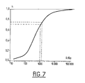
- the representative curve of h is given in Figure 7, a logarithmic scale being used for the R / R E ratio.
- the ionic resistance of the electrolyte can be increased, for example by reducing the number of charge carriers in the polymer, by varying the thickness of the electrolyte or even by using very resistant barrier layers (but still conductive ionic) for example based on tantalum oxide.
- Another possibility is to add to the interface electrically conductive layer / layer of electrochromic material and / or to the interface electrically conductive layer / counter-electrode an additional transparent layer, which has a low but not zero electronic conductivity Ce and an ionic conductivity Ci as low as possible (Ci / Ce ratio very large).
- the process according to the invention makes it possible to obtain a very great uniformity of coloring and a particularly remarkable gain in coloring time in the case of building glazing.
- the compensation of the ionic resistance of the electrolyte however allows only fairly small gains.
- the gains become very appreciable, switching gains of 25 seconds (or 40 seconds) being obtained in the case of building glazing, for a contrast of 3 (or respectively 4) , with a homogeneity of more than 95%.
- the increase in ionic resistance likewise allows a much greater uniformity of coloring, but at the cost of a very significant increase in coloring times which, for a sunroof, already exceed two minutes for a contrast of only 2.
Abstract
Description
La présente invention est relative à l'alimentation d'une cellule électrochrome notamment d'un vitrage à transmission lumineuse électrocommandée. Elle s'applique notamment à toutes les cellules électrochromes de grandes dimensions destinées par exemple au contrôle des apports solaires dans un bâtiment ou dans l'habitat d'un véhicule.The present invention relates to the supply of an electrochromic cell, in particular to a glazing with electrically controlled light transmission. It applies in particular to all large electrochromic cells intended for example for the control of solar gains in a building or in the habitat of a vehicle.
Une cellule électrochrome est constituée d'un empilement de couches comprenant un matériau électrochrome, c'est-à-dire un matériau susceptible d'insérer de façon réversible des cations notamment des protons ou des cations de métaux alcalins et présentant des états de coloration différents entre l'état coloré et l'état décoloré, un électrolyte conducteur ionique, une contre-électrode qui sert de réservoir des cations et qui, comme le matériau électrochrome, doit être capable d'insérer et de désinsérer les cations, symétriquement par rapport à la couche de matériau électrochrome. Dans le cas d'un système fonctionnant en transmission, comme par exemple un vitrage, la contre-électrode se doit également de présenter un état décoloré quand la couche de matériau électrochrome est elle-même à l'état décoloré. Ces conditions font que l'on choisit généralement des couples de matériaux électrochromes cathodiques et anodiques, avec par exemple un matériau cathodique tel que l'oxyde de tungstène WO₃ qui se colore en bleu à l'état inséré en association avec un matériau anodique, tel que l'oxyde d'iridium IrO₂ ou l'oxyde de nickel NiO, décoloré à l'état inséré.An electrochromic cell consists of a stack of layers comprising an electrochromic material, that is to say a material capable of reversibly inserting cations in particular protons or cations of alkali metals and having different states of coloring between the colored state and the discolored state, an ion-conducting electrolyte, a counter-electrode which serves as a reservoir of the cations and which, like the electrochromic material, must be able to insert and de-insert the cations, symmetrically with respect to the layer of electrochromic material. In the case of a system operating in transmission, such as for example a glazing, the counter-electrode must also have a discolored state when the layer of electrochromic material is itself in the discolored state. These conditions mean that couples of cathodic and anodic electrochromic materials are generally chosen, with for example a cathodic material such as tungsten oxide WO₃ which colors blue in the inserted state in association with an anodic material, such than iridium oxide IrO₂ or nickel oxide NiO, discolored in the inserted state.
La couche de matériau électrochrome doit de plus être en contact avec une couche électroconductrice transparente. Il en est de même pour la contre-électrode, encore que cette fois, le caractère transparent ne soit nécessaire que dans le cas des systèmes fonctionnant en transmission. L'empilement est placé en sandwich entre deux substrats, celui côté matériau électrochrome devant être nécessairement transparent, tels que par exemple des plaques de verre.The layer of electrochromic material must also be in contact with a transparent electroconductive layer. The same is true for the counter electrode, although this times, transparency is only necessary in the case of systems operating in transmission. The stack is sandwiched between two substrates, the one on the electrochromic material side having to be necessarily transparent, such as for example glass plates.
Pour faire fonctionner le système, il faut imposer, entre tout couple de deux points en vis-à-vis de part et d'autre de l'électrolyte, une différence de potentiel au moins égale à la différence des potentiels thermodynamiques de la réaction d'insertion/désinsertion souhaitée. En pratique, compte tenu notamment des problèmes d'interface et de la résistance de l'électrolyte, la valeur minimum à imposer est toujours un peu supérieure à la différence des potentiels thermodynamiques. Plus la différence de potentiel appliquée est grande et plus la coloration ou la décoloration sera rapide. Néanmoins, la tension de fonctionnement ne doit pas être trop importante car il importe de ne pas dépasser les tensions permettant des réactions parasites comme par exemple le dégagement d'hydrogène dans le cas d'un système protonique. Pour chaque changement d'état de coloration du système électrochrome, il est ainsi nécessaire de ne pas dépasser une certaine différence de potentiel appelée par la suite potentiel limite du système. Pour fixer les idées, dans le cas d'une cellule du type WO₃/électrolyte protonique/IrO₂, le potentiel limite est de +1,6 Volt en coloration et de -0,6 Volt en décoloration (les signes étant donnés par convention + pour la tension de coloration ; - pour la décoloration ; la tension limite doit donc être considérée en valeur absolue).To operate the system, it is necessary to impose, between any couple of two points facing each other on the electrolyte, a potential difference at least equal to the difference of the thermodynamic potentials of the reaction d 'desired insertion / deinsertion. In practice, taking into account in particular the interface problems and the resistance of the electrolyte, the minimum value to be imposed is always a little higher than the difference of the thermodynamic potentials. The greater the potential difference applied, the faster the coloring or discoloration. However, the operating voltage should not be too high because it is important not to exceed the voltages allowing parasitic reactions such as for example the release of hydrogen in the case of a proton system. For each change of state of coloring of the electrochromic system, it is thus necessary not to exceed a certain difference in potential called hereinafter limit potential of the system. To fix ideas, in the case of a cell of the type WO₃ / proton electrolyte / IrO₂, the limit potential is +1.6 Volt in coloring and -0.6 Volt in discoloration (the signs being given by convention + for coloring voltage; - for discoloration; the limiting voltage must therefore be considered in absolute value).
Les couches électroconductrices du système sont destinées au transfert des charges et la tension n'a à être appliquée qu'entre deux bornes diamétralement opposées du système électrochrome. Mais il va de soi que les couches électroconductrices présentent nécessairement une certaine résistance. Ainsi, dans le cas d'une couche transparente à base d'oxyde d'indium dopé à l'étain (ITO), une résistance carrée de l'ordre de 5 Ohms correspond aujourd'hui à un optimum de conductivité dans des conditions industrielles de production, d'où des chutes ohmiques du système d'autant plus importantes que ses dimensions sont grandes. De ce fait, la différence de potentiel effectivement imposée entre deux points en vis-à-vis est d'autant plus faible que ces points sont éloignés des bornes, avec alors pour ceux-ci un retard très important à la coloration, le maximum de coloration n'étant obtenu qu'après une durée de plusieurs minutes. Quand la taille du système devient grande (par exemple de l'ordre du mètre-carré), la commutation complète du système peut même s'avérer impossible à réaliser.The electroconductive layers of the system are intended for the transfer of charges and the voltage only has to be applied between two diametrically opposite terminals of the electrochromic system. However, it goes without saying that the electrically conductive layers necessarily have a certain resistance. Thus, in the case of a transparent layer based on indium oxide doped with tin (ITO), a square resistance of the order of 5 Ohms today corresponds to an optimum conductivity under industrial conditions of production, where ohmic drops of the system all the more important as its dimensions are large. Therefore, the potential difference actually imposed between two opposite points is even smaller than these points are far from the terminals, with then for these a very important delay in coloring, the maximum coloring not being obtained only after a period of several minutes. When the size of the system becomes large (for example of the order of a square meter), the complete switching of the system may even be impossible to achieve.
Pour s'affranchir de ces chutes ohmiques, les amenées de courant sont systématiquement formées non par des bornes ponctuelles mais par des bandes ou fils très conducteurs, par exemple en cuivre, qui s'étendent le long de deux côtés opposés de la cellule, de sorte que tous les points d'une couche équidistante à un de ces côtés sont équipotentiels. Néanmoins, ceci est loin d'être suffisant dès que la largeur du système électrochrome croît pour dépasser par exemple 10cm, limite à l'évidence incompatible avec la réalisation d'un vitrage bâtiment ou par exemple un toit ouvrant automobile.To overcome these ohmic drops, the current leads are systematically formed not by point terminals but by very conductive strips or wires, for example of copper, which extend along two opposite sides of the cell, so that all the points of a layer equidistant to one of these sides are equipotential. However, this is far from being sufficient as soon as the width of the electrochromic system increases to exceed for example 10cm, a limit which is obviously incompatible with the production of building glazing or, for example, a sunroof for cars.
Dans la demande de brevet européen EP-A-408 427, il a été montré que la vitesse de commutation d'un système électrochrome est sensiblement améliorée si la différence de potentiel appliquée est modulée au cours de la période de commutation de telle sorte que la différence de potentiel entre un point donné de la couche de matériau électrochrome, choisi à proximité immédiate de la bande d'amenée de courant et son point en vis-à-vis de la contre-électrode, reste au cours de cette période de commutation, inférieure à la tension limite pour laquelle des réactions parasites se produisent. Ce procédé d'alimentation connu conduit à appliquer au début d'un cycle de commutation une tension bien plus grande et il en résulte une vitesse de coloration ou de décoloration très sensiblement améliorée, par exemple 6 fois plus grande pour une largeur de vitrage de 30 cm.In European patent application EP-A-408,427, it has been shown that the switching speed of an electrochromic system is significantly improved if the applied potential difference is modulated during the switching period so that the potential difference between a given point in the layer of electrochromic material, chosen in the immediate vicinity of the current supply strip and its point in relation to the counter-electrode, remains during this switching period, lower than the limit voltage for which parasitic reactions occur. This known feeding method leads to applying at the start of a switching cycle a much greater voltage and this results in a very significantly improved coloring or discoloration speed, for example 6 times greater for a glazing width of 30 cm.
Toutefois, pour une largeur de par exemple 1 mètre, les temps de commutation sont encore de plusieurs minutes, du moins si on cherche à obtenir un contraste satisfaisant, par exemple de l'ordre de 4, le contraste étant défini comme le rapport de la transmission lumineuse à l'état décoloré sur la transmission lumineuse à l'état coloré. Par ailleurs, le procédé d'alimentation connu de EP-A-408 427 a tendance à accentuer fortement le contraste constaté en début de commutation entre les bords du vitrage et sa partie centrale. Des rapports de plus 1 pour 2 sont couramment obtenus, ce qui correspond à des différences très perceptibles pour l'oeil.However, for a width of for example 1 meter, the switching times are still several minutes, at least if one seeks to obtain a satisfactory contrast, for example of the order of 4, the contrast being defined as the ratio of the discolored light transmission on the light transmission in the colored state. Furthermore, the feeding method known from EP-A-408 427 tends to strongly accentuate the contrast observed at the start of switching between the edges of the glazing and its central part. Reports of more than 1 for 2 are commonly obtained, which corresponds to differences very perceptible to the eye.
Un premier but de la présente invention est de proposer un nouveau procédé d'alimentation pour systèmes électrochromes permettant des temps de commutation plus courts, tout en garantissant l'intégrité du système et notamment l'absence de réactions parasites. Un autre but des inventeurs est la réduction du contraste entre la partie centrale d'un système électrochrome et ses bords, notamment en début de commutation, lorsque ce contraste est le plus marqué.A first aim of the present invention is to propose a new supply method for electrochromic systems allowing shorter switching times, while guaranteeing the integrity of the system and in particular the absence of parasitic reactions. Another aim of the inventors is to reduce the contrast between the central part of an electrochromic system and its edges, especially at the start of switching, when this contrast is most marked.
Ce problème est résolu selon l'invention en connectant en parallèle avec la cellule électrochrome un élément électrique de référence, équivalent à un élément de la cellule électrochrome de dimensions surfaciques nulles et d'épaisseur d'électrolyte nulle, monté en série avec une résistance Ri, équivalente à la résistance ionique de l'électrolyte de la cellule électrochrome, ramenée à une surface nulle, la tension appliquée aux bornes de la cellule pour la coloration ou la décoloration étant telle que la tension aux bornes de cet élément de référence est maintenue à une valeur inférieure à une tension de référence ou de décoloration.This problem is solved according to the invention by connecting in parallel with the electrochromic cell a reference electrical element, equivalent to an element of the electrochromic cell of zero surface dimensions and of zero electrolyte thickness, connected in series with a resistance R i , equivalent to the ionic resistance of the electrolyte of the electrochromic cell, reduced to a zero surface, the voltage applied to the terminals of the cell for coloring or discoloration being such that the voltage across this reference element is maintained at a value lower than a reference or discoloration voltage.
L'invention consiste ainsi à s'affranchir des chutes de tension dans les couches électroconductrices - dues à sa résistance Re de celles-ci - et dans l'électrolyte - due à la résistance ionique Ri - en montant en parallèle avec la cellule électrochrome un élément électrique qui serait équivalent à une cellule de résistances Re et Ri nulles, mais sans modification de l'impédance de transfert des charges aux interfaces électrolyte/matériau électrochrome et électrolyte/contre-électrode. Autrement dit, l'élément électrique équivalent est une cellule électrochrome où tous les éléments de l'empilement qui entourent les couches d'insertion et de sésinsertion ont un comportement "parfait". A l'aide de cet élément de référence, il est possible de compenser les chutes ohmiques dans l'électrolyte et les couches électroconductrices, permettant ainsi des temps de commutation notablement réduits. Par ailleurs, les chutes ohmiques dans l'électrolyte étant compensées, il devient possible d'utiliser des électrolytes relativement mauvais - ou même très mauvais conducteurs ioniques - ce qui conduit à une plus grande homogénéité surfacique de la teinte pendant les phases de coloration/décoloration.The invention thus consists in overcoming the voltage drops in the electroconductive layers - due to its resistance Re thereof - and in the electrolyte - due to the ionic resistance Ri - by mounting in parallel with the electrochromic cell a electric element which would be equivalent to a cell with zero Re and Ri resistances, but without modification of the charge transfer impedance at the electrolyte / electrochromic material and electrolyte / counter-electrode interfaces. In other words, the equivalent electrical element is an electrochromic cell where all the elements of the stack which surround the insertion and sesinsertion layers have a "perfect" behavior. Using this reference element, it is possible to compensate for ohmic drops in the electrolyte and the layers electrically conductive, allowing significantly reduced switching times. Furthermore, the ohmic drops in the electrolyte being compensated, it becomes possible to use relatively bad electrolytes - or even very bad ionic conductors - which leads to greater surface homogeneity of the color during the coloring / discoloration phases .
Dans une première variante de réalisation de l'invention, l'élément électrique équivalent est constitué par une toute petite cellule électrochrome, de référence par exemple de l'ordre de 1 cm², avec un électrolyte de résistance négligeable devant la résistance ionique de l'électrolyte de la cellule électrochrome principale. Il peut ainsi être utilisé une épaisseur d'électrolyte très réduite et/ou pour la cellule à alimenter un électrolyte de même nature mais moins bon conducteur ionique. Dans le cas d'un électrolyte du type polymère conducteur ionique, on pourra par exemple augmenter, pour la cellule de reference, la quantité de porteurs de charges, sans modifier la matrice de base pour garder les mêmes conditions aux interfaces. Dans le cas d'un électrolyte en couche mince du type diélectrique, on utilisera une couche également plus mince et à plus grande porosité. A noter que cette cellule de référence étant nécessairement très petite pour s'affranchir des chutes ohmiques dues à la résistance des couches électroconductrices, il est possible de se placer dans des conditions très limites qui seraient incompatibles avec un dépôt sur une large surface comme celle d'un vitrage mais qui permettent d'obtenir une résistance ionique dans l'électrolyte très faible. Il est aussi possible de compenser la résistance ionique Ri de la cellule en tenant compte de la résistance ionique ri de la cellule de référence, en montant la cellule de référence en série avec une résistance R'i telle que R'i+ri=Ri ; Ri étant cette fois la résistance de l'électrolyte pour une cellule électrochrome de 1 cm², c'est-à-dire de mêmes dimensions que la cellule de référence. Si ri est petit devant Ri, la compensation de la chute ohmique dans l'électrolyte sera pratiquement totale. Avantageusement encore, la cellule de référence est maintenue systématiquement à une température relativement élevée, par exemple de l'ordre de 60°C, car la résistance ionique décroit avec la température ce qui permet ainsi d'assurer un ri petit. Pour le reste, si on choisit exactement les mêmes matériaux que pour la cellule principale, on obtient un élément qui présente exactement les mêmes impédances de transfert de charges et de diffusion des ions. Par ailleurs, si la cellule électrochrome de référence est placée dans les mêmes conditions de température que la cellule principale, les variations éventuelles de ces impédances, en fonction de la température, seront automatiquement compensées.In a first alternative embodiment of the invention, the equivalent electrical element consists of a very small electrochromic cell, for example of the order of 1 cm², with an electrolyte of negligible resistance compared to the ionic resistance of the electrolyte of the main electrochromic cell. It can thus be used a very reduced electrolyte thickness and / or for the cell to supply an electrolyte of the same kind but less good ionic conductor. In the case of an electrolyte of the ionic conductive polymer type, it is possible for example to increase, for the reference cell, the quantity of charge carriers, without modifying the base matrix to keep the same conditions at the interfaces. In the case of a thin layer electrolyte of the dielectric type, a layer that is also thinner and with greater porosity will be used. Note that this reference cell is necessarily very small to overcome ohmic drops due to the resistance of the electroconductive layers, it is possible to place oneself in very boundary conditions which would be incompatible with a deposit on a large surface like that of 'a glazing but which make it possible to obtain a very low ionic resistance in the electrolyte. It is also possible to compensate for the ionic resistance R i of the cell by taking account of the ionic resistance r i of the reference cell, by mounting the reference cell in series with a resistance R ' i such that R'i + r i = R i ; R i this time being the resistance of the electrolyte for an electrochromic cell of 1 cm², that is to say of the same dimensions as the reference cell. If r i is small compared to R i , the compensation for the ohmic drop in the electrolyte will be practically total. Advantageously also, the reference cell is systematically maintained at a temperature relatively high, for example of the order of 60 ° C, because the ionic resistance decreases with temperature which thus ensures a small r i . For the rest, if we choose exactly the same materials as for the main cell, we obtain an element which has exactly the same impedances of charge transfer and ion diffusion. Furthermore, if the reference electrochromic cell is placed under the same temperature conditions as the main cell, any variations in these impedances, depending on the temperature, will be automatically compensated.
En pratique, il peut être toutefois préférable d'utiliser un élément de référence "tout électrique", modèle de la cellule de référence qui pourra être aisément incorporé dans le circuit électrique d'alimentation de la cellule. Un tel élément de référence "tout électrique" est constitué par un montage électrique - dont l'impédance serait équivalente, pour toute fréquence, à l'impédance d'une unité de surface de la cellule électrochrome - monté en série avec une résistance Ri correspondant à la résistance ionique d'une cellule électrochrome d'une unité de surface.In practice, it may however be preferable to use an "all electric" reference element, model of the reference cell which can be easily incorporated into the electrical supply circuit of the cell. Such an "all-electric" reference element consists of an electrical circuit - the impedance of which would be equivalent, for any frequency, to the impedance of a surface unit of the electrochromic cell - connected in series with a corresponding resistance Ri to the ionic resistance of an electrochromic cell of a surface unit.
Dans ce qui suit, l'unité de surface sera toujours systématiquement choisie égale à 1 cm². Mais il va de soi que toute autre dimension peut être choisie, à la condition toutefois que l'unité de surface reste petite devant les dimensions de la cellule électrochrome à alimenter.In what follows, the surface unit will always be systematically chosen equal to 1 cm². However, it goes without saying that any other dimension may be chosen, provided however that the surface unit remains small compared to the dimensions of the electrochromic cell to be supplied.
Dans la mesure où les cellules électrochromes considérées dans le cadre de l'invention sont grandes et font appel à des temps de coloration/décoloration supérieurs à la dizaine de secondes, ce montage électrique peut être réduit à une résistance R associée en série avec une capacité C. Comme il sera montré plus tard, dans une première approximation, C peut être assimilée au rapport de la quantité de charges insérées dans le matériau électrochrome sur le potentiel à l'équilibre de la cellule, c'est-à-dire du potentiel mesuré après un temps d'homogénéisation suffisant pour permettre une répartition des ions uniforme dans l'épaisseur du matériau électrochrome. La résistance R correspond pour sa part à la somme de la résistance Rt de transfert de charges aux interfaces avec l'électrolyte et d'une résistance RD due à la diffusion des ions dans la cellule.Insofar as the electrochromic cells considered in the context of the invention are large and require coloring / discoloration times greater than ten seconds, this electrical assembly can be reduced to a resistance R associated in series with a capacity C. As will be shown later, in a first approximation, C can be compared to the ratio of the quantity of charges inserted in the electrochromic material to the equilibrium potential of the cell, that is to say the potential measured after a sufficient homogenization time to allow a uniform distribution of the ions in the thickness of the electrochromic material. The resistance R corresponds for its part to the sum of the resistance R t of charge transfer to interfaces with the electrolyte and an RD resistance due to the diffusion of ions in the cell.
Il importe de noter que les valeurs de RT, RD, RI et C dépendent uniquement de la nature et de l'épaisseur des différentes couches du matériau. Il en est de même pour Re, la résistance carrée des couches électroconductrices. Autrement dit, l'élément de référence et la résistance Ri qui lui est associée sont parfaitement indépendants de la taille du système, ce qui permet d'utiliser une alimentation unique (à la condition toutefois que celle-ci soit capable de délivrer la puissance nécessaire qui pour sa part, croît avec la taille de la cellule électrochrome).It is important to note that the values of R T , R D , R I and C depend only on the nature and the thickness of the different layers of the material. It is the same for R e , the square resistance of the electroconductive layers. In other words, the reference element and the resistance R i which is associated with it are perfectly independent of the size of the system, which makes it possible to use a single power supply (on the condition, however, that this is capable of delivering the power necessary which for its part increases with the size of the electrochromic cell).
Il peut être montré que l'uniformité de la couleur au tout début de la coloration ou de la décoloration dépend du rapport RT+RD+Ri/Re. Si on définit l'homogénéité à partir du rapport des tensions initiales effectives à l'instant zéro au centre et sur les bords de la cellule par des amenées de courant, on a constaté qu'une homogénéité de plus de 70 % est obtenue lorsque ce rapport est supérieur à 1000. L'homogénéité de coloration est de l'ordre de 95 % pour un rapport de 10 000. Les résistances de transfert et de diffusion étant limitantes de la vitesse de coloration dans le procédé selon l'invention, il importe toutefois de ne pas augmenter le terme RT+RD. Par contre, il est avantageux d'utiliser des couches électroconductrices de très faible résistivité. Par ailleurs, l'électrolyte est de préférence choisi avec une résistance ionique grande, de préférence au moins égale à 500 fois la résistance carrée des couches électroconductrices, sans excéder de préférence 100 000 fois cette valeur, car alors la puissance qui doit être fournie au vitrage devient très grande.It can be shown that the uniformity of the color at the very start of coloring or discoloration depends on the ratio R T + R D + R i / R e . If we define homogeneity from the ratio of effective initial voltages at time zero at the center and on the edges of the cell by current leads, we have found that homogeneity of more than 70% is obtained when this ratio is greater than 1000. The coloring uniformity is of the order of 95% for a ratio of 10 000. The transfer and diffusion resistances being limiting of the coloring speed in the process according to the invention, it is important however, not to increase the term R T + R D. On the other hand, it is advantageous to use electroconductive layers of very low resistivity. Furthermore, the electrolyte is preferably chosen with a large ionic resistance, preferably at least equal to 500 times the square resistance of the electroconductive layers, without preferably exceeding 100,000 times this value, since then the power which must be supplied to the glazing becomes very large.
Pour augmenter la résistance ionique de l'électrolyte il est possible comme indiqué précédemment de moduler son épaisseur et/ou sa quantité de porteurs de charges (dans le cas d'un électrolyte polymère conducteur ionique), ou sa porosité (dans le cas d'un diélectrique). Il est aussi possible de placer l'électrolyte entre deux couches barrières très résistantes comme par exemple des couches de diélectriques du type Ta₂O₅ à très faibles porosités, la résistance ionique de l'ensemble constitué par l'électrolyte et les deux couches barrières étant de préférence compris entre 10 000 et 100 000 Ohms. Des valeurs plus grandes imposent des tensions d'alimentation trop importantes. Par ailleurs, même si la résistance ionique peut avantageusement être élevée, l'électrolyte doit bien sûr conserver une certaine conductivité pour permettre la réalisation des équilibres thermodynamiques. De préférence encore, la conductivité ionique de l'électrolyte dans cet empilement avec couches barrières est choisie supérieure à 10⁻³ Ohm⁻¹.To increase the ionic resistance of the electrolyte it is possible, as indicated above, to modulate its thickness and / or its quantity of charge carriers (in the case of an ionic conductive polymer electrolyte), or its porosity (in the case of a dielectric). It is also possible to place the electrolyte between two very resistant barrier layers such as, for example, dielectric layers of the Ta₂O₅ type with very low porosities, the ionic resistance of the assembly formed by the electrolyte and the two barrier layers preferably being between 10,000 and 100,000 ohms. Larger values impose too high supply voltages. Furthermore, even if the ionic resistance can advantageously be high, the electrolyte must of course retain a certain conductivity to allow the achievement of thermodynamic equilibria. More preferably, the ionic conductivity of the electrolyte in this stack with barrier layers is chosen to be greater than 10⁻³ Ohm⁻¹.
Pour tenir compte de la diminution de la résistance ionique de l'électrolyte quand la température croît, il est préférable d'utiliser pour les résistances Ri des thermistances ou des montages électroniques équivalents dont la résistance varie avec la température comme la résistance de l'électrolyte. Des thermistances peuvent être également utilisées pour les résistances RT et RD mais le facteur température est moins critique et de plus RT + RD est petit devant Ri, l'emploi de thermistances est donc moins justifié. Dans le domaine de températures d'utilisation des cellules électrochromes, la capacité C ne semble pas dépendre de la température.To take into account the decrease in the ionic resistance of the electrolyte when the temperature increases, it is preferable to use for resistors R i thermistors or equivalent electronic assemblies whose resistance varies with temperature as the resistance of the electrolyte. Thermistors can also be used for resistors R T and R D but the temperature factor is less critical and moreover R T + R D is small compared to R i , the use of thermistors is therefore less justified. In the field of temperatures of use of electrochromic cells, the capacity C does not seem to depend on the temperature.
Nous avons dit plus haut que le modèle simplifié d'impédance est valable pour des temps de commutation relativement longs. En pratique, il conduit à minimiser la différence de potentiel appliquée à la cellule en tout début de commutation, autrement dit à plafonner le courant et donc la vitesse initiale de coloration ou de décoloration. Pour y remédier, il peut être utilisé comme indiqué précédemment un montage électrique reproduisant pour chaque fréquence, l'impédance de la cellule ou un montage semi-simplifié comportant outre la résistance R et la capacité C, une capacité C' montée en parallèle avec la capacité C.We said above that the simplified impedance model is valid for relatively long switching times. In practice, it leads to minimizing the potential difference applied to the cell at the very start of switching, in other words to cap the current and therefore the initial speed of coloring or discoloration. To remedy this, it can be used as indicated above an electrical circuit reproducing for each frequency, the impedance of the cell or a semi-simplified circuit comprising in addition to the resistance R and the capacitance C, a capacitance C 'connected in parallel with the capacity C.
D'autres détails et caractéristiques avantageuses de l'invention ressortent de la description détaillée faite ci-après en référence aux dessins annexés qui représentent :
- * figure 1 : un schéma de principe d'une cellule électrochrome selon la demande de brevet européen EP-A-408 427,
- * figure 2 : une modélisation de la cellule électrochrome de la figure 1 représentée par un réseau à 7 mailles,
- * figure 3 : un schéma d'un circuit électrique équivalent à une interface de type électrolyte / matériau électrochrome,
- * figure 4 : une courbe représentant la quantité de charge insérée (en milli-Coulombs par centimètre carréà en fonction du potentiel à l'abandon de la cellule,
- * figure 5 : un modèle d'un circuit électrique équivalent à la cellule électrochrome de la figure 1,
- * figure 6 : la courbe représentant la différence de potentiel appliquée au cours du temps pour une cellule réelle conforme à la figure 1 ou selon le modèle de la figure 5,
- * figure 7 : une courbe représentant le facteur d'homogénéité du vitrage en fonction de la valeur du rapport Rd+RT+Ri/Re,
- * figure 8 : un modèle d'une cellule avec un élément de référence selon l'invention.
- * Figure 1 : a block diagram of an electrochromic cell according to European patent application EP-A-408,427,
- * figure 2: a modeling of the electrochromic cell of FIG. 1 represented by a 7-mesh network,
- * Figure 3: a diagram of an electrical circuit equivalent to an electrolyte / electrochromic material interface,
- * Figure 4: a curve representing the amount of charge inserted (in milli-Coulombs per square centimeter as a function of the cell abandonment potential,
- * Figure 5 : a model of an electrical circuit equivalent to the electrochromic cell of Figure 1,
- * Figure 6: the curve representing the potential difference applied over time for a real cell in accordance with Figure 1 or according to the model in Figure 5,
- * Figure 7: a curve representing the homogeneity factor of the glazing as a function of the value of the ratio R d + R T + R i / R e ,
- * Figure 8: a model of a cell with a reference element according to the invention.
Pour simplifier, nous nous limiterons pour la suite de ce mémoire à des cellules électrochromes constituées de l'empilement de couches suivantes représenté à la figure 1 :
- * une couche électroconductrice 1 à base d'oxyde d'indium (ITO) déposée par exemple par pulvérisation cathodique magnétron,
- * un matériau électrochrome cathodique 2 (WO₃),
- * un électrolyte conducteur protonique 3,
- * une contre-
électrode 4, matériau électrochrome anodique IrO₂ protonée avant l'assemblage, - * une couche électroconductrice 5 identique à (1).
- an
electroconductive layer 1 based on indium oxide (ITO) deposited for example by magnetron sputtering, - * a cathodic electrochromic material 2 (WO₃),
- * a
proton conducting electrolyte 3, - * a
counter-electrode 4, anodic electrochromic material IrO₂ protonated before assembly, - * an electrically conductive layer 5 identical to (1).
Les équilibres thermodynamiques qui interviennent dans les réactions de coloration/décoloration peuvent s'écrire :
Pour éviter des réactions parasités, notamment à la formation d'hydrogène, à 20°C, les différences de potentiels limites sont de 1,6 Volt en coloration et -0,6 Volt en décoloration. Mais il doit être noté que ces tensions limites correspondent aux différences de potentiels locales entre un point situé côté WO₃ et son vis-à-vis côté IrO₂. La différence de potentiel appliquée à la cellule peut en fait être bien plus élevée tant que pour tout couple de points en vis-à-vis, la tension limite n'est pas dépassée.To avoid parasitic reactions, in particular with the formation of hydrogen, at 20 ° C, the differences in limit potentials are 1.6 Volt in coloring and -0.6 Volt in discoloration. But it should be noted that these limit voltages correspond to the local potential differences between a point located on the WO côté side and its opposite side IrO₂. The potential difference applied to the cell can in fact be much higher as long as for any pair of points opposite, the limit voltage is not exceeded.
Dans ce qui suit, nous nous limiterons au cas de la coloration, mais il va de soi que ce qui sera dit s'applique également pour les phases de décoloration, en utilisant les tensions limites adéquates.In what follows, we will limit ourselves to the case of coloring, but it goes without saying that what will be said also applies for the discoloration phases, using the appropriate limit voltages.
Dans le cas de l'alimentation proposée par la demande de brevet EP-A-408 427, la différence de potentiel appliquée par le générateur entre les bandes métalliques ou métallisées 6 et 7 (bornes W et CE) est telle que la différence de potentiel UREF, entre la borne W et la borne R en vis-à-vis de la couche IrO₂, soit maintenue inférieure à la tension limite de 1,6 Volt pendant toute la durée d'une coloration. Ceci revient à appliquer en début de coloration, une différence de potentiel relativement élevée qui va décroître selon une courbe exponentielle au cours de la coloration. Le gain de temps est très grand par rapport à une alimentation à tension constante, néanmoins, des temps de coloration supérieurs à 2 minutes (pour un contraste de 4) sont encore nécessaires, avec des couches électroconductrices d'une résistance carrée de 5 Ohms.In the case of the power supply proposed by patent application EP-A-408,427, the potential difference applied by the generator between the metal or metallized strips 6 and 7 (terminals W and CE) is such that the potential difference U REF , between terminal W and terminal R opposite the IrO₂ layer, is kept below the limit voltage of 1.6 Volt throughout the duration of a coloration. This amounts to applying at the start of coloring, a relatively high potential difference which will decrease according to an exponential curve during coloring. The time saving is very large compared to a constant voltage supply, however, coloring times greater than 2 minutes (for a contrast of 4) are still necessary, with electrically conductive layers with a square resistance of 5 Ohms.
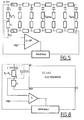
Pour une meilleure compréhension des phénomènes limitant les cinétiques de réaction, il a été procédé à une modélisation électrique de la cellule. Pour celà, la cellule électrochrome est maillée en N bandes parallèles aux bandes latérales d'amenée de courant. Sur la figure 1, on a représenté ainsi 7 bandes. Si ces bandes sont assez nombreuses, et donc correspondent chacune à un très faible écartement par rapport à la distance entre les bandes d'amenée de courant, on peut considérer que dans chacune de ces bandes, la chute de potentiel due à l'ITO est négligeable, de sorte que la cellule électrochrome peut être représentée par le réseau électrique de la figure 2, c'est-à-dire par un ensemble de 7 petits éléments de cellules connectées deux à deux par deux résistances Re. Dans la pratique, une bonne corrélation avec les valeurs réelles mesurées par des cellules d'au plus 1 m de large est constatée pour un maillage avec N = 41.For a better understanding of the phenomena limiting the reaction kinetics, an electrical modeling of the cell was carried out. For this, the electrochromic cell is meshed in N bands parallel to the lateral current supply bands. In Figure 1, 7 bands are thus represented. If these bands are numerous enough, and therefore each correspond to a very small spacing with respect to the distance between the current supply bands, it can be considered that in each of these bands, the drop in potential due to ITO is negligible, so that the electrochromic cell can be represented by the electrical network of FIG. 2, that is to say by a set of 7 small elements of cells connected two by two by two Re resistors. good correlation with actual values measured by cells no larger than 1 m wide is noted for a mesh with N = 41.
Chacun de ces éléments peut, du point de vue électrique, être représenté par son circuit électrique dit de Randles représenté à la figure 3 et décrit dans l'article de C. Ho, I.D. RAISTRICK et R.A. HUGGINS paru dans le "Journal of Electrochemical Society - n° 127 - page 343 - (1980). Dans ce circuit, Ri représente la résistance ionique de l'électrolyte, Rt la résistance de transfert de charge aux interfaces WO₃/électrolyte et électrolyte/IrO₂, Cd la capacité de double couche à ces interfaces et Zw l'impédance de Warburg de la cellule prenant en compte la diffusion des espèces ioniques dans WO₃ et IrO₂.Each of these elements can, from an electrical point of view, be represented by its so-called Randles electrical circuit represented in FIG. 3 and described in the article by C. Ho, ID RAISTRICK and RA HUGGINS published in the "Journal of Electrochemical Society - n ° 127 - page 343 - (1980) In this circuit, R i represents the ionic resistance of the electrolyte, R t the charge transfer resistance at the interfaces WO₃ / electrolyte and electrolyte / IrO₂, Cd the capacity of double layer at these interfaces and Z w the Warburg impedance of the cell taking into account the diffusion of ionic species in WO₃ and IrO₂.
L'impédance Z de ce modèle électrique peut être simplifiée dans deux cas limites. Au temps = O, si on applique une tension Vo, l'intensité du courant mesuré tend vers Vo/Ri, la mesure du courant Io permet donc d'accéder à la valeur de Ri.The Z impedance of this electric model can be simplified in two borderline cases. At time = O, if a voltage V o is applied, the intensity of the measured current tends towards V o / R i , the measurement of the current I o therefore gives access to the value of R i .
Par ailleurs, à basse fréquence ( W < 0,1 Hz), la capacité de double couche Cd devient négligeable et l'impédance de diffusion se réduit à une résistance de diffusion en série avec une capacité C. L'impédance Z peut alors s'écrire Z = Ri + Rt + Rd - j/Cw.Furthermore, at low frequency (W <0.1 Hz), the double layer capacitance Cd becomes negligible and the diffusion impedance is reduced to a diffusion resistance in series with a capacitance C. The impedance Z can then s 'write Z = R i + R t + R d - j / Cw.
La capacité C de la cellule électrochrome peut être calculée à partir de la courbe de la figure 4 où est représentée en ordonnées la quantité de charges insérées dans WO₃ et en abscisse le potentiel à l'abandon de la cellule, c'est-à-dire le potentiel d'équilibre de la cellule mesuré lorsque l'alimentation électrique est coupée, après un temps d'homogénéisation de quelques minutes, suffisant pour s'affranchir des problèmes de diffusion des ions. Comme on peut le voir sur cette figure 4, le potentiel d'équilibre croît de manière approximativement linéaire avec la quantité de charges insérées dans une relation de type Q = CV, ce qui dans le cas de l'empilement considéré, permet de trouver une valeur de capacité égale à 9,9 mF/cm².The capacitance C of the electrochromic cell can be calculated from the curve of FIG. 4 where the quantity of charges inserted in WO₃ is represented on the ordinate and on the abscissa the potential for abandonment of the cell, that is to say say the equilibrium potential of the cell measured when the power supply is cut, after a homogenization time of a few minutes, sufficient to overcome the problems of ion diffusion. As can be seen in this figure 4, the equilibrium potential increases in an approximately linear manner with the quantity of charges inserted in a relation of type Q = CV, which in the case of the considered stack, makes it possible to find a capacity value equal to 9.9 mF / cm².
Les valeurs précises de RD et de RT dépendent de l'état de coloration de la cellule. Connaissant par ailleurs la valeur de résistance Re, on peut ajuster la valeur de R = RD + RT + Ri de façon à ce que l'impédance Z = R-J/Cw corresponde à la valeur expérimentale. On a donc établi pour différentes valeurs de R la courbe illustrée à la figure 6 donnant la tension de coloration en fonction du temps d'une part pour une cellule expérimentale (courbe en pointillés) et d'autre part pour différentes valeurs de R, dans le modèle électrique représenté à la figure 5 (mais en choisissant un paramètre de mailles N = 41), jusqu'à obtenir par approximation successive une valeur satisfaisante pour R. La courbe en traits pleins de la figure 5 a ainsi été obtenue en choisissant R = 3400 Ohms, ce qui nous permet d'approximer pour RT + RD la valeur de 2400 Ohms sachant que la résistance ionique calculée à partir de la mesure de l'intensité Io et de la tension appliquée Vo est de l'ordre de 1000 Ohms.The precise values of R D and R T depend on the state of staining of the cell. Knowing moreover the resistance value R e , the value of R = R D + R T + R i can be adjusted so that the impedance Z = RJ / C w corresponds to the experimental value. So we established for different values of R the curve illustrated in FIG. 6 giving the coloring voltage as a function of time on the one hand for an experimental cell (dotted curve) and on the other hand for different values of R, in the electric model represented at FIG. 5 (but by choosing a parameter of meshes N = 41), until obtaining by successive approximation a satisfactory value for R. The curve in solid lines of FIG. 5 was thus obtained by choosing R = 3400 Ohms, this which allows us to approximate for R T + R D the value of 2400 Ohms knowing that the ionic resistance calculated from the measurement of the intensity I o and the applied voltage V o is of the order of 1000 Ohms.
Il est ainsi possible de réaliser une bonne modélisation du système aux temps longs en connaissant avec une bonne approximation les valeurs de Ri, RT + RD, Re et C. Comme on peut le voir également sur la figure 6, ce modèle simple n'est pas valable pour les 10 premières secondes de coloration, (il a été approximé pour des basses fréquences). Pour celles-ci, il faut complexifier le modèle par exemple en ajoutant une capacité C', montée en parallèle. Après 10 secondes toutefois, la cellule électrochrome peut bien être modélisée par un schéma tel que celui de la figure 5, l'intensité entre la borne W et la borne de référence étant maintenue par exemple inférieure ou égale à la tension limite de coloration au moyen d'un amplificateur différentiel ayant un gain très important par exemple de l'ordre de G = 10⁶.It is thus possible to carry out a good modeling of the system with long times by knowing with a good approximation the values of R i , R T + R D , R e and C. As we can also see it on figure 6, this model simple is not valid for the first 10 seconds of coloring (it has been approximated for low frequencies). For these, the model must be made more complex, for example by adding a capacity C ′, mounted in parallel. After 10 seconds, however, the electrochromic cell may well be modeled by a diagram such as that of FIG. 5, the intensity between the terminal W and the reference terminal being maintained for example less than or equal to the limit coloring voltage by means a differential amplifier having a very large gain, for example of the order of G = 10⁶.
Si l'électrode de référence est placée non entre Re et Ri comme dans le cas du montage décrit par la demande de brevet européen EP-A-408 427 mais comme indiqué par la ligne pointillée en E, donc entre (RT + RD) et Ri, la chute de tension dans l'électrolyte va pouvoir être compensée. De cette façon, la tension d'alimentation appliquée au système entre les bornes W et CE pour maintenir une tension de référence de 1,6 Volt va devoir être augmentée, avec pour conséquence des temps de coloration plus courts. Plus la résistance ionique de l'électrolyte est grande, plus le gain en temps de coloration sera grand. Néanmoins, il faut tenir compte également des tensions d'alimentation admissibles pour l'application de la cellule électrochrome (dans une automobile il est par exemple préférable de se limiter à une tension d'alimentation maximum de 12 Volts, par contre pour un vitrage bâtiment une limite de 110 ou 220 Volts peut être choisie). De plus, l'augmentation de la résistance ionique Ri implique une augmentation de la puissance dissipée et des pertes par effet Joule. Dans la pratique, un compromis doit donc être fait entre le temps de coloration souhaité et les caractéristiques de l'alimentation électrique.If the reference electrode is placed not between R e and R i as in the case of the assembly described by European patent application EP-A-408 427 but as indicated by the dotted line at E, therefore between (R T + RD) and R i , the drop in voltage in the electrolyte will be able to be compensated. In this way, the supply voltage applied to the system between the terminals W and CE to maintain a reference voltage of 1.6 Volts will have to be increased, with the consequence of shorter coloring times. The greater the ionic resistance of the electrolyte, the greater the gain in coloring time. However, it is also necessary to take into account the admissible supply voltages for the application of the electrochromic cell (in a automotive it is for example preferable to be limited to a maximum supply voltage of 12 Volts, on the other hand for building glazing a limit of 110 or 220 Volts can be chosen). In addition, the increase in the ionic resistance Ri implies an increase in the dissipated power and losses by the Joule effect. In practice, a compromise must therefore be made between the desired coloring time and the characteristics of the power supply.
En pratique, il va de soi que l'électrode de référence ne peut être placée entre (RT + RD) et Ri comme dans le cas de la figure 5. Toutefois, il est possible d'adjoindre une "maille" supplémentaire au réseau sous la forme d'une petite cellule électrochrome ou d'un élément électrique de référence qui, comme indiqué dans le montage schématisé à la figure 8, est connecté en parallèle avec la cellule. A noter que dans le cas où l'élément de référence est constitué par une cellule électrochrome de petites dimensions, il doit être tenu compte de la résistance ionique ri de la cellule de référence, et on utilise alors une résistance R'i telle que R'i = Ri ri.In practice, it goes without saying that the reference electrode cannot be placed between (R T + R D ) and R i as in the case of FIG. 5. However, it is possible to add an additional "mesh" to the network in the form of a small electrochromic cell or an electrical reference element which, as shown in the diagram shown in Figure 8, is connected in parallel with the cell. Note that in the case where the reference element consists of an electrochromic cell of small dimensions, account must be taken of the ionic resistance r i of the reference cell, and a resistance R ′ i is then used such that R ' i = R i r i .
L'élément de référence, aux bornes duquel est contrôlée la tension de référence est ainsi simplement constitué par une capacité C et une résistance (Rt + Rd), les valeurs des composants C, (RT + RD) et Ri étant déterminées pour chaque type d'empilement électrochrome par le programme de modélisation et les courbes de tension et de courant caractéristiques de la cellule électrochrome. Pour accélérer la cinétique de coloration aux temps courts, il est avantageux d'ajouter une capacité C', en parallèle avec C et (RT + RD) qui permet de tenir compte de la variation d'impédance en début de coloration.The reference element, at the terminals of which the reference voltage is controlled, is thus simply constituted by a capacitance C and a resistance (R t + R d ), the values of the components C, (R T + R D ) and R i being determined for each type of electrochromic stack by the modeling program and the voltage and current curves characteristic of the electrochromic cell. To accelerate the kinetics of coloring at short times, it is advantageous to add a capacitance C ′, in parallel with C and (R T + R D ) which makes it possible to take account of the variation in impedance at the start of coloring.
Par ailleurs, le modèle électrique de référence a permis de calculer le facteur h d'homogénéité de coloration (h étant défini comme le rapport de la tension au centre de la cellule sur la tension aux bords près des amenées de courant) en fonction de la valeur du rapport R/Re où R = RT + RD + Ri. La courbe représentative de h est donnée à la figure 7, une échelle logarithmique étant utilisée pour la rapport R/RE.Furthermore, the electric reference model made it possible to calculate the h color homogeneity factor (h being defined as the ratio of the voltage at the center of the cell to the voltage at the edges near the current leads) as a function of the value of the ratio R / R e where R = R T + R D + R i . The representative curve of h is given in Figure 7, a logarithmic scale being used for the R / R E ratio.
Très clairement, il est avantageux de réduire Re mais nous avons déjà indiqué que cette réduction se heurtait très vite à des difficultés techniques et physiques qui interdisent des couches à la fois très électroconductrices et très transparentes. De fait, il est difficile de faire varier le rapport R/Re de plus d'un facteur 3 en jouant sur la valeur de Re. Par contre, la résistance ionique de l'électrolyte peut être augmentée par exemple en diminuant le nombre de porteurs de charge dans le polymère, en jouant sur l'épaisseur de l'électrolyte ou encore en utilisant des couches barrières très résistantes (mais encore conductrices ioniques) par exemple à base d'oxyde de tantale. Une autre possibilité est d'ajouter à l'interface couche électroconductrice/couche de matériau électrochrome et/ou à l'interface couche électroconductrice/contre-électrode une couche additionnelle transparente, qui présente une conductivité électronique Ce faible mais non nulle et une conductivité ionique Ci aussi faible que possible (rapport Ci/Ce très grand).Very clearly, it is advantageous to reduce R e but we have already indicated that this reduction very quickly encountered technical and physical difficulties which prohibit layers which are both very electrically conductive and very transparent. In fact, it is difficult to vary the ratio R / R e by more than a factor of 3 by varying the value of R e . On the other hand, the ionic resistance of the electrolyte can be increased, for example by reducing the number of charge carriers in the polymer, by varying the thickness of the electrolyte or even by using very resistant barrier layers (but still conductive ionic) for example based on tantalum oxide. Another possibility is to add to the interface electrically conductive layer / layer of electrochromic material and / or to the interface electrically conductive layer / counter-electrode an additional transparent layer, which has a low but not zero electronic conductivity Ce and an ionic conductivity Ci as low as possible (Ci / Ce ratio very large).
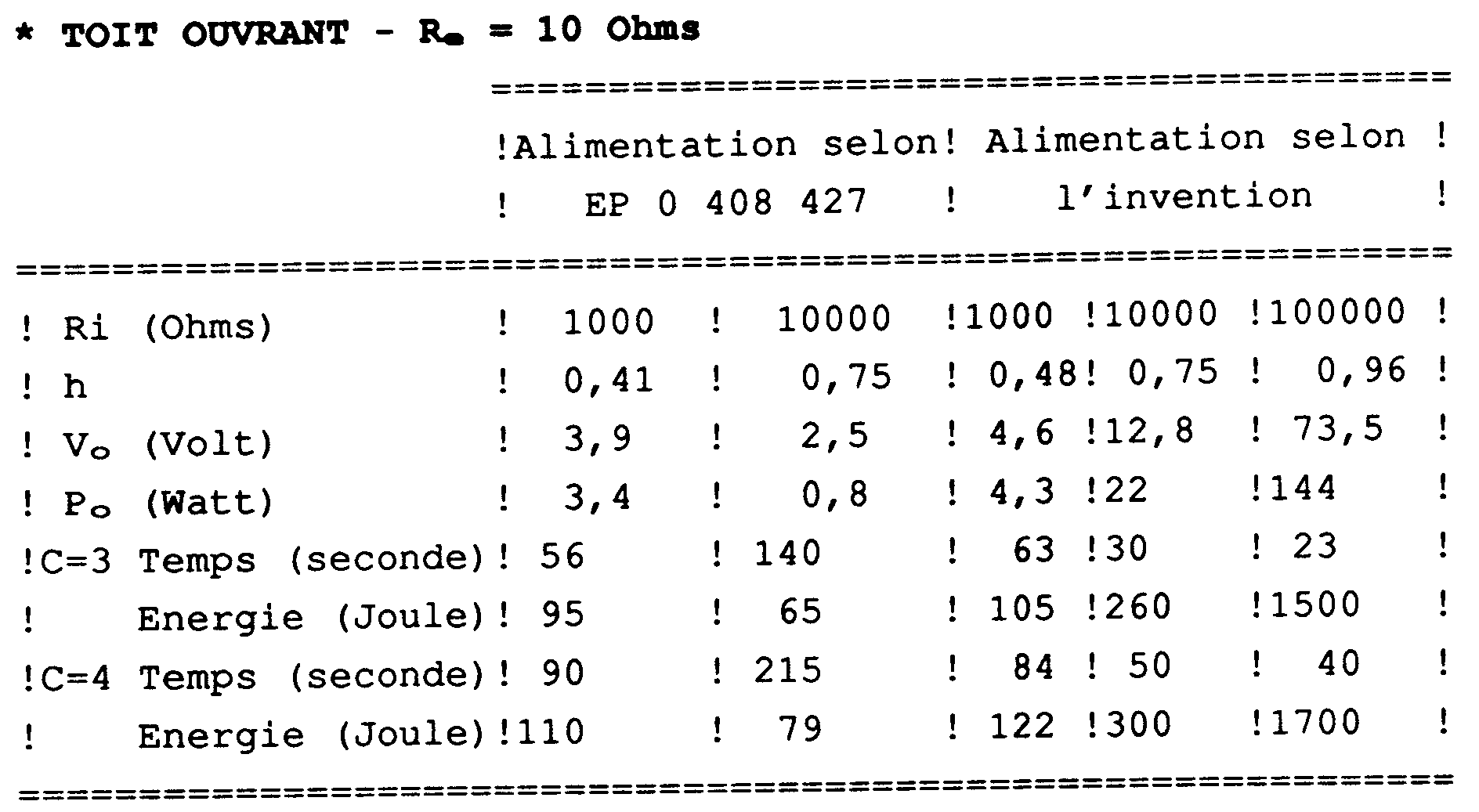
La comparaison entre l'invention et un montage selon l'art, avec pourtant une compensation de la résistance Re des couches électroconductrices, a été faites pour deux types de vitrages, un toit électrochrome dont la surface de coloration a pour dimension 40 cm X 74 cm et un vitrage bâtiment de dimensions utiles 100 cm x 200 cm, les simulations ayant été effectuées en prenant les valeurs respectives suivantes RT + RD = 2400 Ohms et C = 10 mF/cm² déterminées expérimentalement.The comparison between the invention and an assembly according to the art, yet with compensation for the resistance R e of the electroconductive layers, was made for two types of glazing, an electrochromic roof whose coloring surface has the dimension of 40 cm X 74 cm and building glazing with
Comme les tableaux annexés le montrent, le procédé selon l'invention permet d'obtenir une uniformité très grande de la coloration et un gain en temps de coloration particulièrement remarquable dans le cas d'un vitrage bâtiment.As the attached tables show, the process according to the invention makes it possible to obtain a very great uniformity of coloring and a particularly remarkable gain in coloring time in the case of building glazing.
Avec une simple modification du circuit d'alimentation, la compensation de la résistance ionique de l'électrolyte ne permet toutefois que des gains assez petits. Par contre, si on augmente la valeur de Ri, les gains deviennent très appréciables, des gains de commutation de 25 secondes (ou 40 secondes) étant obtenus dans le cas du vitrage bâtiment, pour un contraste de 3 (ou respectivement de 4), avec une homogénéité de plus de 95 %. Sans compensation de la résistance ionique, on note que l'augmentation de la résistance ionique permet de même une uniformité de coloration bien plus grande, mais au prix d'une augmentation très importante des temps de coloration qui, pour un toit ouvrant, dépassent déjà les deux minutes pour un contraste de seulement 2.


Claims (17)
Applications Claiming Priority (2)
| Application Number | Priority Date | Filing Date | Title |
|---|---|---|---|
| FR929209931A FR2694820B1 (en) | 1992-08-12 | 1992-08-12 | Supply of an electrochromic cell. |
| FR9209931 | 1992-08-12 |
Publications (2)
| Publication Number | Publication Date |
|---|---|
| EP0584003A1 true EP0584003A1 (en) | 1994-02-23 |
| EP0584003B1 EP0584003B1 (en) | 1998-05-20 |
Family
ID=9432791
Family Applications (1)
| Application Number | Title | Priority Date | Filing Date |
|---|---|---|---|
| EP93402001A Expired - Lifetime EP0584003B1 (en) | 1992-08-12 | 1993-08-04 | Power supply for an electrochromic cell |
Country Status (7)
| Country | Link |
|---|---|
| US (1) | US5402144A (en) |
| EP (1) | EP0584003B1 (en) |
| JP (1) | JPH06160915A (en) |
| CA (1) | CA2103936A1 (en) |
| DE (1) | DE69318645T2 (en) |
| DK (1) | DK0584003T3 (en) |
| FR (1) | FR2694820B1 (en) |
Families Citing this family (49)
| Publication number | Priority date | Publication date | Assignee | Title |
|---|---|---|---|---|
| FR2706639B1 (en) * | 1993-06-11 | 1995-08-25 | Saint Gobain Vitrage Int | Electrochromic glazing. |
| FR2719915B1 (en) * | 1994-05-16 | 1996-06-14 | Saint Gobain Vitrage | Electrochromic system and its supply process. |
| US6178034B1 (en) | 1996-04-10 | 2001-01-23 | Donnelly Corporation | Electrochromic devices |
| DE19706918A1 (en) * | 1997-02-20 | 1998-08-27 | Flachglas Ag | Method for operating an electrochromic element |
| US5978126A (en) * | 1998-09-21 | 1999-11-02 | Ppg Industries Ohio, Inc. | Apparatus for controlling an electrochromic device |
| US5973818A (en) * | 1998-09-21 | 1999-10-26 | Ppg Industries Ohio, Inc. | Method and apparatus for controlling an electrochromic device |
| US5973819A (en) * | 1998-09-21 | 1999-10-26 | Ppg Industries Ohio, Inc. | Method and apparatus for controlling an electrochromic device |
| US8432603B2 (en) | 2009-03-31 | 2013-04-30 | View, Inc. | Electrochromic devices |
| TWI416999B (en) * | 2009-08-21 | 2013-11-21 | Iner Aec Executive Yuan | A plasma generating device with new circuit design |
| US11592723B2 (en) | 2009-12-22 | 2023-02-28 | View, Inc. | Automated commissioning of controllers in a window network |
| US10690540B2 (en) | 2015-10-06 | 2020-06-23 | View, Inc. | Multi-sensor having a light diffusing element around a periphery of a ring of photosensors |
| US20130271813A1 (en) | 2012-04-17 | 2013-10-17 | View, Inc. | Controller for optically-switchable windows |
| US8213074B1 (en) | 2011-03-16 | 2012-07-03 | Soladigm, Inc. | Onboard controller for multistate windows |
| US10303035B2 (en) | 2009-12-22 | 2019-05-28 | View, Inc. | Self-contained EC IGU |
| US11314139B2 (en) | 2009-12-22 | 2022-04-26 | View, Inc. | Self-contained EC IGU |
| US8254013B2 (en) | 2011-03-16 | 2012-08-28 | Soladigm, Inc. | Controlling transitions in optically switchable devices |
| US9454055B2 (en) | 2011-03-16 | 2016-09-27 | View, Inc. | Multipurpose controller for multistate windows |
| US10935865B2 (en) | 2011-03-16 | 2021-03-02 | View, Inc. | Driving thin film switchable optical devices |
| US9030725B2 (en) | 2012-04-17 | 2015-05-12 | View, Inc. | Driving thin film switchable optical devices |
| US11630367B2 (en) | 2011-03-16 | 2023-04-18 | View, Inc. | Driving thin film switchable optical devices |
| US9412290B2 (en) | 2013-06-28 | 2016-08-09 | View, Inc. | Controlling transitions in optically switchable devices |
| US11054792B2 (en) | 2012-04-13 | 2021-07-06 | View, Inc. | Monitoring sites containing switchable optical devices and controllers |
| US9645465B2 (en) | 2011-03-16 | 2017-05-09 | View, Inc. | Controlling transitions in optically switchable devices |
| US8705162B2 (en) | 2012-04-17 | 2014-04-22 | View, Inc. | Controlling transitions in optically switchable devices |
| US9778532B2 (en) | 2011-03-16 | 2017-10-03 | View, Inc. | Controlling transitions in optically switchable devices |
| CN106930675B (en) | 2011-10-21 | 2019-05-28 | 唯景公司 | Mitigate the thermal shock in pigmentable window |
| RU2017140197A (en) | 2011-12-12 | 2019-02-12 | Вью, Инк. | THIN FILM DEVICES AND THEIR MANUFACTURE |
| US11635666B2 (en) | 2012-03-13 | 2023-04-25 | View, Inc | Methods of controlling multi-zone tintable windows |
| US11950340B2 (en) | 2012-03-13 | 2024-04-02 | View, Inc. | Adjusting interior lighting based on dynamic glass tinting |
| US11300848B2 (en) | 2015-10-06 | 2022-04-12 | View, Inc. | Controllers for optically-switchable devices |
| EP3611707B1 (en) | 2012-04-13 | 2024-01-17 | View, Inc. | Applications for controlling optically switchable devices |
| US10503039B2 (en) | 2013-06-28 | 2019-12-10 | View, Inc. | Controlling transitions in optically switchable devices |
| US10964320B2 (en) | 2012-04-13 | 2021-03-30 | View, Inc. | Controlling optically-switchable devices |
| US10048561B2 (en) | 2013-02-21 | 2018-08-14 | View, Inc. | Control method for tintable windows |
| US11674843B2 (en) | 2015-10-06 | 2023-06-13 | View, Inc. | Infrared cloud detector systems and methods |
| US9638978B2 (en) | 2013-02-21 | 2017-05-02 | View, Inc. | Control method for tintable windows |
| US11719990B2 (en) | 2013-02-21 | 2023-08-08 | View, Inc. | Control method for tintable windows |
| US9091897B2 (en) * | 2013-03-16 | 2015-07-28 | Tintable Smart Material Co., Ltd. | Transmittance control method of electrochromic component |
| US9885935B2 (en) | 2013-06-28 | 2018-02-06 | View, Inc. | Controlling transitions in optically switchable devices |
| US10221612B2 (en) | 2014-02-04 | 2019-03-05 | View, Inc. | Infill electrochromic windows |
| KR102336168B1 (en) | 2014-03-05 | 2021-12-07 | 뷰, 인크. | Monitoring sites containing switchable optical devices and controllers |
| GB201423311D0 (en) * | 2014-12-29 | 2015-02-11 | Pilkington Group Ltd | Switchable device |
| TWI823168B (en) | 2015-07-07 | 2023-11-21 | 美商唯景公司 | Viewcontrol methods for tintable windows |
| US11255722B2 (en) | 2015-10-06 | 2022-02-22 | View, Inc. | Infrared cloud detector systems and methods |
| EP3929395B1 (en) | 2015-10-29 | 2024-03-13 | View, Inc. | Controllers for optically-switchable devices |
| CA3022490A1 (en) | 2016-04-29 | 2017-11-02 | View, Inc. | Calibration of electrical parameters in optically switchable windows |
| US11454854B2 (en) | 2017-04-26 | 2022-09-27 | View, Inc. | Displays for tintable windows |
| TW202206925A (en) | 2020-03-26 | 2022-02-16 | 美商視野公司 | Access and messaging in a multi client network |
| US11631493B2 (en) | 2020-05-27 | 2023-04-18 | View Operating Corporation | Systems and methods for managing building wellness |
Citations (4)
| Publication number | Priority date | Publication date | Assignee | Title |
|---|---|---|---|---|
| JPS63157132A (en) * | 1986-12-19 | 1988-06-30 | Hitachi Maxell Ltd | Electrochromic display element |
| JPH0246428A (en) * | 1988-08-08 | 1990-02-15 | Toyota Motor Corp | Driving device for electrochromic display element |
| EP0408427A1 (en) * | 1989-07-11 | 1991-01-16 | Saint-Gobain Vitrage International | Electrochromic window |
| US5073011A (en) * | 1989-10-31 | 1991-12-17 | Toyoda Gosei Co., Ltd. | Electrochromic device with a reference electrochromic element |
Family Cites Families (2)
| Publication number | Priority date | Publication date | Assignee | Title |
|---|---|---|---|---|
| DE3142907A1 (en) * | 1981-10-29 | 1983-05-11 | Fa. Carl Zeiss, 7920 Heidenheim | OPTICAL CONTROL CIRCUIT FOR ELECTROCHROME LAYERS |
| JPH0291529A (en) * | 1988-09-29 | 1990-03-30 | Toppan Printing Co Ltd | Normal paper number inspection device |
-
1992
- 1992-08-12 FR FR929209931A patent/FR2694820B1/en not_active Expired - Fee Related
-
1993
- 1993-08-04 DE DE69318645T patent/DE69318645T2/en not_active Expired - Fee Related
- 1993-08-04 DK DK93402001T patent/DK0584003T3/en active
- 1993-08-04 EP EP93402001A patent/EP0584003B1/en not_active Expired - Lifetime
- 1993-08-12 US US08/104,758 patent/US5402144A/en not_active Expired - Fee Related
- 1993-08-12 JP JP5200630A patent/JPH06160915A/en active Pending
- 1993-08-12 CA CA002103936A patent/CA2103936A1/en not_active Abandoned
Patent Citations (4)
| Publication number | Priority date | Publication date | Assignee | Title |
|---|---|---|---|---|
| JPS63157132A (en) * | 1986-12-19 | 1988-06-30 | Hitachi Maxell Ltd | Electrochromic display element |
| JPH0246428A (en) * | 1988-08-08 | 1990-02-15 | Toyota Motor Corp | Driving device for electrochromic display element |
| EP0408427A1 (en) * | 1989-07-11 | 1991-01-16 | Saint-Gobain Vitrage International | Electrochromic window |
| US5073011A (en) * | 1989-10-31 | 1991-12-17 | Toyoda Gosei Co., Ltd. | Electrochromic device with a reference electrochromic element |
Non-Patent Citations (2)
| Title |
|---|
| PATENT ABSTRACTS OF JAPAN vol. 012, no. 422 (P - 783) * |
| PATENT ABSTRACTS OF JAPAN vol. 014, no. 207 (P - 1043) * |
Also Published As
| Publication number | Publication date |
|---|---|
| DE69318645D1 (en) | 1998-06-25 |
| DK0584003T3 (en) | 1999-03-08 |
| JPH06160915A (en) | 1994-06-07 |
| FR2694820A1 (en) | 1994-02-18 |
| US5402144A (en) | 1995-03-28 |
| CA2103936A1 (en) | 1994-02-13 |
| EP0584003B1 (en) | 1998-05-20 |
| FR2694820B1 (en) | 1994-09-16 |
| DE69318645T2 (en) | 1999-02-25 |
Similar Documents
| Publication | Publication Date | Title |
|---|---|---|
| EP0584003B1 (en) | Power supply for an electrochromic cell | |
| EP0475847B1 (en) | Electrochromic window | |
| EP0408427B1 (en) | Electrochromic window | |
| EP0683419B1 (en) | Method of supplying power to an electrochromic system | |
| EP0628849B1 (en) | Electrochromic window | |
| EP1451634B1 (en) | Electrochemical/electro-controllable device electrode | |
| FR2569872A1 (en) | OPTICAL DEVICE WITH VARIABLE TRANSMISSION AND METHOD OF MANUFACTURING SUCH A DEVICE | |
| FR2791147A1 (en) | ELECTROCHEMICAL DEVICE OF THE ELECTROCOMMANDABLE DEVICE TYPE WITH VARIABLE OPTICAL AND / OR ENERGY PROPERTIES | |
| EP0373020B1 (en) | Counter-electrode for electrochromic devices | |
| FR2669124A1 (en) | BISTABLE ELECTROOPTIC DEVICE, SCREEN COMPRISING SUCH A DEVICE AND METHOD FOR IMPLEMENTING SAID SCREEN. | |
| EP0082052B1 (en) | Electrochromic display device with thermo-electric control | |
| FR2575303A1 (en) | ELECTROCHROMIC SOLID STATE DEVICE WITH LOW VOLTAGE SIDE COLORING | |
| FR2969771A1 (en) | ELECTROCHEMICAL DEVICE HAVING ELECTRO-CONTROLLABLE OPTICAL AND / OR ENERGY TRANSMISSION PROPERTIES | |
| FR2551902A1 (en) | NON-LINEAR ELEMENT ADDRESSING DISPLAY SCREEN AND METHOD FOR MANUFACTURING THE SAME | |
| Kaneko et al. | Effects of transparent electrode resistance on the performance characteristics of electrochemichromic cells | |
| EP0006811A2 (en) | Metal precipitate electrolytic display cell and method to avoid an impoverishment of metal at certain zones of the counter-electrode of such a cell | |
| EP0557159B1 (en) | Electrochromic device | |
| WO2016066931A1 (en) | Reflective cell with modular reflectivity | |
| FR2633609A1 (en) | Electrochromic system | |
| FR2689655A1 (en) | Electrochromic-electrolyte cell for coating large surfaces e.g. vehicle or building window variable absorption filter - has electrode which ensures even distribution of resistance from connection point of external power supply using conductive grid or layer having resistance values related to distance from point. | |
| FR2561423A1 (en) | Electrically-controlled visual display device | |
| WO2021123267A1 (en) | Thermal tempering of a working electrode | |
| FR2933208A1 (en) | INSULATING ELECTRODE FOR ELECTROCHEMICAL DEVICE | |
| EP0065894A1 (en) | Electrolytic display cell comprising a transparent back electrode |
Legal Events
| Date | Code | Title | Description |
|---|---|---|---|
| PUAI | Public reference made under article 153(3) epc to a published international application that has entered the european phase |
Free format text: ORIGINAL CODE: 0009012 |
|
| AK | Designated contracting states |
Kind code of ref document: A1 Designated state(s): BE CH DE DK FR GB IT LI NL SE |
|
| 17P | Request for examination filed |
Effective date: 19940812 |
|
| 17Q | First examination report despatched |
Effective date: 19960503 |
|
| GRAG | Despatch of communication of intention to grant |
Free format text: ORIGINAL CODE: EPIDOS AGRA |
|
| GRAG | Despatch of communication of intention to grant |
Free format text: ORIGINAL CODE: EPIDOS AGRA |
|
| GRAH | Despatch of communication of intention to grant a patent |
Free format text: ORIGINAL CODE: EPIDOS IGRA |
|
| RAP1 | Party data changed (applicant data changed or rights of an application transferred) |
Owner name: SAINT-GOBAIN VITRAGE |
|
| GRAH | Despatch of communication of intention to grant a patent |
Free format text: ORIGINAL CODE: EPIDOS IGRA |
|
| GRAA | (expected) grant |
Free format text: ORIGINAL CODE: 0009210 |
|
| AK | Designated contracting states |
Kind code of ref document: B1 Designated state(s): BE CH DE DK FR GB IT LI NL SE |
|
| REG | Reference to a national code |
Ref country code: CH Ref legal event code: EP |
|
| REF | Corresponds to: |
Ref document number: 69318645 Country of ref document: DE Date of ref document: 19980625 |
|
| ITF | It: translation for a ep patent filed |
Owner name: RACHELI & C. S.R.L. |
|
| GBT | Gb: translation of ep patent filed (gb section 77(6)(a)/1977) |
Effective date: 19980805 |
|
| REG | Reference to a national code |
Ref country code: CH Ref legal event code: NV Representative=s name: KIRKER & CIE SA |
|
| REG | Reference to a national code |
Ref country code: DK Ref legal event code: T3 |
|
| PLBE | No opposition filed within time limit |
Free format text: ORIGINAL CODE: 0009261 |
|
| STAA | Information on the status of an ep patent application or granted ep patent |
Free format text: STATUS: NO OPPOSITION FILED WITHIN TIME LIMIT |
|
| 26N | No opposition filed | ||
| PGFP | Annual fee paid to national office [announced via postgrant information from national office to epo] |
Ref country code: DK Payment date: 20010803 Year of fee payment: 9 |
|
| PGFP | Annual fee paid to national office [announced via postgrant information from national office to epo] |
Ref country code: DE Payment date: 20010913 Year of fee payment: 9 |
|
| PGFP | Annual fee paid to national office [announced via postgrant information from national office to epo] |
Ref country code: CH Payment date: 20011106 Year of fee payment: 9 |
|
| REG | Reference to a national code |
Ref country code: GB Ref legal event code: IF02 |
|
| PGFP | Annual fee paid to national office [announced via postgrant information from national office to epo] |
Ref country code: GB Payment date: 20020731 Year of fee payment: 10 |
|
| PGFP | Annual fee paid to national office [announced via postgrant information from national office to epo] |
Ref country code: SE Payment date: 20020806 Year of fee payment: 10 |
|
| PGFP | Annual fee paid to national office [announced via postgrant information from national office to epo] |
Ref country code: FR Payment date: 20020812 Year of fee payment: 10 |
|
| PGFP | Annual fee paid to national office [announced via postgrant information from national office to epo] |
Ref country code: NL Payment date: 20020829 Year of fee payment: 10 |
|
| PG25 | Lapsed in a contracting state [announced via postgrant information from national office to epo] |
Ref country code: LI Free format text: LAPSE BECAUSE OF NON-PAYMENT OF DUE FEES Effective date: 20020831 Ref country code: DK Free format text: LAPSE BECAUSE OF NON-PAYMENT OF DUE FEES Effective date: 20020831 Ref country code: CH Free format text: LAPSE BECAUSE OF NON-PAYMENT OF DUE FEES Effective date: 20020831 |
|
| PGFP | Annual fee paid to national office [announced via postgrant information from national office to epo] |
Ref country code: BE Payment date: 20020919 Year of fee payment: 10 |
|
| PG25 | Lapsed in a contracting state [announced via postgrant information from national office to epo] |
Ref country code: DE Free format text: LAPSE BECAUSE OF NON-PAYMENT OF DUE FEES Effective date: 20030301 |
|
| REG | Reference to a national code |
Ref country code: DK Ref legal event code: EBP |
|
| REG | Reference to a national code |
Ref country code: CH Ref legal event code: PL |
|
| PG25 | Lapsed in a contracting state [announced via postgrant information from national office to epo] |
Ref country code: GB Free format text: LAPSE BECAUSE OF NON-PAYMENT OF DUE FEES Effective date: 20030804 |
|
| PG25 | Lapsed in a contracting state [announced via postgrant information from national office to epo] |
Ref country code: SE Free format text: LAPSE BECAUSE OF NON-PAYMENT OF DUE FEES Effective date: 20030805 |
|
| PG25 | Lapsed in a contracting state [announced via postgrant information from national office to epo] |
Ref country code: BE Free format text: LAPSE BECAUSE OF NON-PAYMENT OF DUE FEES Effective date: 20030831 |
|
| BERE | Be: lapsed |
Owner name: *SAINT-GOBAIN VITRAGE Effective date: 20030831 |
|
| PG25 | Lapsed in a contracting state [announced via postgrant information from national office to epo] |
Ref country code: NL Free format text: LAPSE BECAUSE OF NON-PAYMENT OF DUE FEES Effective date: 20040301 |
|
| GBPC | Gb: european patent ceased through non-payment of renewal fee |
Effective date: 20030804 |
|
| EUG | Se: european patent has lapsed | ||
| PG25 | Lapsed in a contracting state [announced via postgrant information from national office to epo] |
Ref country code: FR Free format text: LAPSE BECAUSE OF NON-PAYMENT OF DUE FEES Effective date: 20040430 |
|
| NLV4 | Nl: lapsed or anulled due to non-payment of the annual fee |
Effective date: 20040301 |
|
| REG | Reference to a national code |
Ref country code: FR Ref legal event code: ST |
|
| PG25 | Lapsed in a contracting state [announced via postgrant information from national office to epo] |
Ref country code: IT Free format text: LAPSE BECAUSE OF NON-PAYMENT OF DUE FEES;WARNING: LAPSES OF ITALIAN PATENTS WITH EFFECTIVE DATE BEFORE 2007 MAY HAVE OCCURRED AT ANY TIME BEFORE 2007. THE CORRECT EFFECTIVE DATE MAY BE DIFFERENT FROM THE ONE RECORDED. Effective date: 20050804 |