EP0582443A1 - Air bag container for high performance inflator and hinge therefor - Google Patents
Air bag container for high performance inflator and hinge therefor Download PDFInfo
- Publication number
- EP0582443A1 EP0582443A1 EP93306020A EP93306020A EP0582443A1 EP 0582443 A1 EP0582443 A1 EP 0582443A1 EP 93306020 A EP93306020 A EP 93306020A EP 93306020 A EP93306020 A EP 93306020A EP 0582443 A1 EP0582443 A1 EP 0582443A1
- Authority
- EP
- European Patent Office
- Prior art keywords
- hinge
- cover
- air bag
- container
- wall
- Prior art date
- Legal status (The legal status is an assumption and is not a legal conclusion. Google has not performed a legal analysis and makes no representation as to the accuracy of the status listed.)
- Granted
Links
Images


Classifications
-
- B—PERFORMING OPERATIONS; TRANSPORTING
- B60—VEHICLES IN GENERAL
- B60R—VEHICLES, VEHICLE FITTINGS, OR VEHICLE PARTS, NOT OTHERWISE PROVIDED FOR
- B60R21/00—Arrangements or fittings on vehicles for protecting or preventing injuries to occupants or pedestrians in case of accidents or other traffic risks
- B60R21/02—Occupant safety arrangements or fittings, e.g. crash pads
- B60R21/16—Inflatable occupant restraints or confinements designed to inflate upon impact or impending impact, e.g. air bags
- B60R21/20—Arrangements for storing inflatable members in their non-use or deflated condition; Arrangement or mounting of air bag modules or components
- B60R21/215—Arrangements for storing inflatable members in their non-use or deflated condition; Arrangement or mounting of air bag modules or components characterised by the covers for the inflatable member
- B60R21/2165—Arrangements for storing inflatable members in their non-use or deflated condition; Arrangement or mounting of air bag modules or components characterised by the covers for the inflatable member characterised by a tear line for defining a deployment opening
- B60R21/21656—Steering wheel covers or similar cup-shaped covers
-
- E—FIXED CONSTRUCTIONS
- E05—LOCKS; KEYS; WINDOW OR DOOR FITTINGS; SAFES
- E05D—HINGES OR SUSPENSION DEVICES FOR DOORS, WINDOWS OR WINGS
- E05D1/00—Pinless hinges; Substitutes for hinges
- E05D1/02—Pinless hinges; Substitutes for hinges made of one piece
-
- E—FIXED CONSTRUCTIONS
- E05—LOCKS; KEYS; WINDOW OR DOOR FITTINGS; SAFES
- E05Y—INDEXING SCHEME RELATING TO HINGES OR OTHER SUSPENSION DEVICES FOR DOORS, WINDOWS OR WINGS AND DEVICES FOR MOVING WINGS INTO OPEN OR CLOSED POSITION, CHECKS FOR WINGS AND WING FITTINGS NOT OTHERWISE PROVIDED FOR, CONCERNED WITH THE FUNCTIONING OF THE WING
- E05Y2900/00—Application of doors, windows, wings or fittings thereof
- E05Y2900/10—Application of doors, windows, wings or fittings thereof for buildings or parts thereof
- E05Y2900/13—Application of doors, windows, wings or fittings thereof for buildings or parts thereof characterised by the type of wing
- E05Y2900/132—Doors
Landscapes
- Engineering & Computer Science (AREA)
- Mechanical Engineering (AREA)
- Air Bags (AREA)
- Purses, Travelling Bags, Baskets, Or Suitcases (AREA)
- Respiratory Apparatuses And Protective Means (AREA)
- Superstructure Of Vehicle (AREA)
Abstract
Description
- The present invention relates to a new and improved, cosmetic, container or enclosure for a driver's side module of a high performance type air bag or inflator. More particularly, the present invention is directed towards a new and improved air bag container having a novel hinge structure especially designed for use with a high performance inflator. The hinge is effective to retain a cover or panel of the enclosure during and after deployment of the air bag even though hot and cold environmental conditions obtain and yet readily permit the cover or panel to open under the pressure of air bag inflation. The open panel or cover is retained against separation from the enclosure side wall so as to prevent damage to the air bag or injury to the occupants in the vehicle in which the air bag is deployed.
- U.S. Patent No. 3,199,913 discloses a vehicle sun shade or visor wherein the article is formed substantially entirely of molded plastic material with an integral hinge therein permitting vertical and horizontal movement of the sun shade as desired.
- U.S. Patent No. 3,551,940 discloses a box hinge for use with containers and packaging enclosure employing a hinge integrally formed of plastic sheet material permitting flexibility and a relatively wide range of pivotal movement without breakage or distortion.
- U.S. Patent No. 3,767,229 discloses an inflatable dash panel construction for protecting automobile occupants in collisions and the like wherein a one-piece element of relatively thick material is provided as a padded dash assembly and which element is designed to provide a supportive cushion to protect an occupant upon inflation of a chamber behind the element.
- U.S. Patent No. 4,183,550 is directed towards an air bag holding container which has an improved shearing resistance in an area surrounding a gas generator.
- U.S. Patent No. 4,414,705 discloses an integral thermoplastic biasing hinge useful for container caps or tops and is adapted to retain the top or cap either in a fully closed or in a fully open position.
- U.S. Patent No. 4,968,057 discloses a cover assembly for an air bag unit including first and second separate door members, each having a polyvinylchloride outer shell, a urethane foam pad and a yieldable thin metal back plate.
- U.S. Patent No. 5,044,663 discloses a blow molded air bag having internal fabric reinforcements for providing supplemental support during inflation.
- U.S. Patent No. 5,069,477 discloses a pad for an air bag device including a reinforcing metallic member embedded in at least a front and rear side wall of an insert member made of synthetic resin.
- A problem for air bag containers utilized for holding high performance inflators has been the tendency of pieces or parts of a cover member especially when formed of metal to come loose and inadvertently cut or slice open the air bag during the inflation process and/or strike occupants of the vehicle causing injury. These types of problems have tended to limit the overall safety characteristics of many air bag enclosures.
- Another problem encountered with prior art air bag enclosures is the fact that sometimes a cover portion of the air bag enclosure must be fractured or broken away from the main body of the enclosure retained on the steering wheel in order for the air bag to deploy and if the fractured portion thereafter becomes separated from the rapidly inflating air bag, it could be propelled or move away in a variety of uncontrolled directions to possibly cause injury to an occupant or damage the interior of the vehicle.
- Yet another problem with prior art air bag enclosures is that it is difficult to provide a high performance cover for a driver side module that is also pleasing in design or appearance, and wherein the cover panel is stiff, flat and able to withstand normal driving abuse without breaking yet does not tear or cut open an air bag while the bag is being deployed. In high performance types of air bag inflators, attempts at using plastic injection molded reinforcement elements rather than metal reinforcing plates have been successful to some extent when operated at non-severe temperature conditions, but many times these air bag enclosures have failed in the region of hinged attachment of a door or panel to a stationary position of the enclosure when deployed at relatively extreme or severe hot or cold conditions.
- It is therefore an object of the present invention to provide a new and improved air bag container or enclosure and more particularly a new and improved hinge system for a high performance air bag inflator, which hinge system insures that the air bag is firmly retained behind a relatively strong cover panel structure while not in use and yet which cover panel will permit rapid deployment of the air bag in a manner whereby the panel portions that hinge open are positively retained with a fixed portion of an enclosure so as not to cause injury to occupants of the vehicle, and/or damage to the air bag itself or the interior of the vehicle.
- Yet another object of the present invention is to provide a new and improved hinge system for use with an openable cover of a container for a high performance inflatable air bag, which hinge system permits a wide angle of pivotal movement of an opening panel so as to provide little or no interference with a rapid deployment of the air bag during inflation and yet at the same time provides for positive retainment of the opened panel or door with a fixed wall portion of the enclosure.
- Yet another object of the present invention is to provide a new and improved hinge structure that is useful in connection with a stiffening or reinforcing element provided in a front face or cover panel of an air bag containing enclosure.
- Still another object of the present invention is to provide a new and improved air bag container of the type described which is pleasing to the eye, especially reliable and safe in operation and which can be constructed and installed on an economical basis to provide a highly effective safety device for use in motor vehicles and the like.
- Still another object of the present invention is to provide a new and improved air bag container and hinge structure therefor which is effective to allow door or panel to fracture or break away along predetermined fracture lines in order to rapidly open up and yet is strong enough to withstand accelerating forces and masses involved and capable of preventing the opened door or panel from becoming a loose projectile when the air bag is deployed.
- The foregoing and other objects and advantages of the present invention are accomplished in an illustrated embodiment comprising an enclosure or container for a high performance inflatable air bag including a fixed wall portion and an integral cover portion intersecting one another around a peripheral front edge of the enclosure. A new and improved hinge system includes a pair of spaced apart hinges. Each hinge is secured on the inside of a fixed wall portion and to a panel or door segment on the cover for retaining attachment between the two when the cover is fractured or broken away from the fixed wall portion to pivot outwardly during rapid inflation of the air bag. Each hinge is formed of a piece of scrim material comprising strong, woven, flexible fibers and having a first section attached to the cover and a second section attached to the fixed wall of the air bag enclosure. An intermediate hinge section is integral with the first and second sections and the integral hinge section includes a portion overlying one of said sections and integrally joined along a fold line extending along an edge of the enclosure or container. When the air bag is deployed, the cover is fractured along a groove adjacent the center thereby forming a pair of separate panels or doors which pivot away from one another to release the inflating air bag. The flexible scrim material of each hinge permits unfolding along a fold line but the scrim material remains positively attached to prevent the door or panel from completely separating from the fixed wall structure. Because the pivoting doors or panels never become completely detached from the fixed wall portion of the enclosure, and cuts or damage to the air bag, injuries to a person in the vehicle or damage to adjacent interior surfaces of the vehicle are precluded.
- Fracture of the cover into a pair of pivotally opening doors or panels is facilitated by grooves on the inside of the cover reducing the thickness of the walls along intended lines of fracture.
- Preferably, each hinge includes a plurality of overlapping web portions in an intermediate hinge section thereof and these web portions are separated from one another by a strip of tape or layer of impervious sheet material so that as the scrim material is enveloped in resinous plastic material during the molding process, the resin does not bond together the overlapping web portion when the resin solidifies. In addition, in each hinge, a strip of tape is also provided between a web portion of the hinge section and an adjacent first or second section of the hinge secured to an adjacent enclosure wall so that solidified resin does not preclude pivotal movement as a panel or door opens upon inflation of the air bag. A new and unique type of plastic stiffening element is provided to reinforce the wall structure of the air bag enclosure and the stiffening element is molded-in-place within the wall structure as it is formed with plastic resin.
- The invention will now be described by way of example with reference to the following drawings in which:
- FIG. 1 is a front elevational view of a new and improved air bag container constructed in accordance with the features of the present invention and illustrated as mounted in place on the steering wheel of a vehicle;
- FIG. 2 is a transverse cross-sectional view taken substantially along lines 2-2 of FIG. 1;
- FIG. 2A is a view similar to FIG. 2 but showing the air bag container after panels have opened upon inflation and deployment of the air bag for protecting the occupant of the vehicle;
- FIG. 3 is a rear elevational view of a front cover of the air bag container;
- FIG. 4 is a rear side elevational view illustrating a stiffening element for the front cover adapted to be molded-in-place and showing new and unique hinges constructed in accordance with the features of the present invention mounted on the stiffening element before being joined thereto by the injection of resinous plastic material used for the walls and cover of the enclosure;
- FIG. 5 is a front elevational view looking at the stiffening element of FIG. 4;
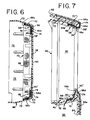
- FIG. 6 is a transverse cross-sectional view taken substantially along lines 6-6 of FIG. 4 showing the hinges in place before the introduction of resinous plastic material used in forming the enclosure;
- FIG. 7 is an enlarged fragmentary vertical cross-sectional view like FIG. 2A, showing the hinges and respective cover doors or panels after a deployment of the air bag has taken place; and
- FIG. 8 is a graph representing the pressure within the air bag versus time after initiating air bag deployment.
- Referring now more particularly to the drawings, therein is illustrated a new and improved air bag enclosure or
container 10 adapted to be mounted on a motorvehicle steering wheel 12 and designed to contain a high performanceinflatable air bag 14 in a folded up condition before deployment as shown in FIG. 2. Thecontainer 10 is adapted to open up upon rapid inflation of theair bag 14 to an expanded condition as shown in FIG. 2A wherein the air bag is effective to prevent injury to a person oroccupant 16 behind thesteering wheel 12 in case of an accident. Theair bag 14 is formed of strong, lightweight, thin, flexible plastic sheet material which is airtight and is adapted to be rapidly inflated with gas discharged through a metal inlet fitting 18 having a plurality ofwall ports 20 spaced in a ring around a side wall thereof. Theinlet fitting 18 is generally cylindrical and is mounted in a central opening provided in aninternal back plate 22 in theair bag container 10. Theback plate 22 is generally rectangular or square in a front elevational view and has a somewhat pie-shaped profile configuration in a side view (FIGS. 2 and 2A). An intermediate flange extending around the cylindrical side wall of theinflator inlet fitting 18 is secured to theback plate 22 and to a ring-like element 24 by a plurality ofsuitable fasteners 26 for sealing theair bag 14 around the inlet fitting in place in an airtight connection. - The
air bag container 10 includes an outerback cover member 28, preferably formed of strong, lightweight, injection molded plastic resin material and supported from the steering column structure on which thesteering wheel 12 is mounted. As best shown in FIGS. 2 and 2A, the outerback cover member 28 includes a forwardly extending peripheral, edge flange orside wall 30 of generally rectangular shape dimensioned to interfit and join with an outerfront cover member 32, also preferably formed of a strong, lightweight injection molded plastic resin material such as a gas or foam filled, high density polyurethane resin or polyester resin. - The
front cover member 32 includes a generally rectangular-shaped, relatively stiff and strongfront wall 34 which is reinforced internally as will be described hereinafter and the front wall is integrally joined around peripheral edges to a continuous peripheral flange-like side wall 36 (FIG. 3) comprising anupper wall 38, alower wall 40 and a pair ofopposite side walls 42. As best shown in FIGS. 2 and 2A, rearwardly facing ends of theperipheral side wall 36 of thefront cover member 32 are adapted to bond with forwardly facing ends of theperipheral wall 30 of the outerback wall structure 28 to form a tight, strong enclosure (FIG. 2) for containing theair bag 14 under normal operating conditions. - In accordance with the present invention, in order to strengthen the
air bag container 10, a strengthening or reinforcingelement 46 is integrally molded in place in thefront cover member 32. The reinforcingmember 46 is generally similar in shape to thefront cover member 32 and includes afront wall 48 formed with a plurality of square and diamond-shaped openings distributed over substantially all of the surface area thereof for allowing plastic resin to pass therethrough in the molding process to form the outside surface of thefront cover member 32. In addition to the plurality of small perforations, the front wall is formed with a series of alignedslots 50 extending from edge to edge at a generally mid-level or centerline as best shown in FIGS. 4, 5 and 6. In addition, thefront wall 48 includes a line ofslots 52 extending vertically along opposite edges and joining the opposite ends of the center line ofslots 50. At the upper ends, theside edge slots 52 are joined with a pair of short oppositely inwardly directed lines ofslots 54 positioned along an upper edge of thefront wall 48. Inner end slots of the line ofslots 54, are provided with an enlargedrounded aperture 55 as best shown in FIGS. 4 and 5, and similarly, along a lower edge of thefront wall 48 of the reinforcingelement 46, there is provided a pair of short oppositely inwardly directed lines ofslots 56 joining the lower end of the side edge line ofslots 52. Inner end slots of theline slots 56 are formed with an enlargedrounded aperture 57. - Along an upper edge portion of the
front wall 48 between the enlargedapertures 55 is provided a line of relativelywide slots 58 corresponding to an upper hinge axis of thecontainer 10. Similarly, between theenlarged apertures 57 along the lower edge of thefront wall 48 there is provided a line of relatively widelower edge slots 60 corresponding to a lower hinge axis of thecontainer 10. The center line ofslots 50, the upper line ofslots 58 and the lower line ofslots 60 are generally parallel of each other and identify lines of fracture in thefront wall 34 of thefront cover 32 of theair bag container 10 when theair bag 14 is rapidly deployed by inflation. These lines of intended fracture are shown in dotted line form on FIG. 1 and divide thefront wall 34 of thecover member 32 into an upper panel ordoor 62 and a lower panel ordoor 64, both of generally rectangular shape. The upper line ofslots 58 and lower line ofslots 60 generally define elongated axes of hinges for supporting and retaining the upper and lower panels ordoors centerline 50 during deployment of theair bag 14. Moreover, fracture also occurs along the vertical lines ofopposite edge slots 52 in the outer surface of thefront wall 34. - In accordance with the features of the present invention, the
air bag container 10 includes a pair of new andunique hinges 66 constructed from strips of tough, strong, flexible, resilient, wovenscrim material formed of resinous plastic fibers such as that sold under the trademark "NYLON". The scrim material is woven with an open weave as shown in FIG. 4 and is especially adapted for positively retaining the upper and lower panels ordoors peripheral edge wall 72 of thefront cover member 32 during and after deployment of theair bag 14 as shown in FIG. 7. As shown in FIG. 4, the scrim material of thehinges 66 extends longitudinally between theenlarged apertures 55 along theupper hinge line 58 and between theenlarged apertures 57 along thelower hinge line 60. - Each
hinge 66 includes a relatively large sizefirst section 66a adapted to be secured to either anupper panel 62 orlower panel 64 in thefront wall 34 of thefront cover member 32. As illustrated in FIGS. 4 and 6, thefirst hinge sections 66a are adapted to bear against the back side face of thefront wall 48 of the reinforcingelement 46 and because both the reinforcing element and the hinge material have a large area of open space, the plastic resin used in the injection molding process to form thefront cover member 32 can flow through and bond together thefirst section 66a of each hinge 66 with thefront wall 48 as the outer layer of resinous plastic material making up thefront wall 34 of thefront cover member 32 is molded-in-place. The hinges 66 also includesecond sections 66b initially secured in place by means of staples or the like 68 to a layer of openweave reinforcing tape 70 secured around the insideperipheral wall 72 of the reinforcingelement 46 as best shown in FIGS. 4 and 6. Because both thehinge sections 66b and thetape 70 are made of open weave material, injection molding plastic resin can flow through and around these elements to positively secure thehinge sections 66b in a molded-in-place condition with the respective upper andlower walls front cover member 32. - Each
hinge 66 is also provided with a pair of integral, folded over webs or hingeportions first section 66a (FIGS. 4 and 6) before the injection of molded plastic material takes place. - The
overlying web portions panels side wall structure 36 of thefront cover member 32 during and after deployment of theair bag 14. The panels are permanently secured to the peripheral fixedside wall 36 even though fracture of thefront wall 34 intoseparate panels lines air bag 14. This arrangement ensures that theair bag 14 itself is not punctured or cut during deployment and that the cover doors orpanels - Referring to FIGS. 6 and 7, in order to permit free pivotal movement around longitudinally extending fold lines (generally the same as the fracture lines 58 and 60) and free pivotal movement about inner parallel fold lines 58' and 60' at the folds between
web portions plastic material 74 are interposed between the folded over, overlyingweb portions hinge 66 and between theoverlying hinge portions 66d and thefirst sections 66a of each hinge 77 adjacent the respective panels ordoors tape 74 prevent resin from filling in between the overlying webs of the open weave scrim material of thehinges 66 so that free pivotal movement along the fold lines 58, 58' and 60, 60' is achieved without any retarding action caused because of solidified resin. - Referring now to FIG. 3, which illustrates a back side view of the
front cover member 32 after the injection molding process has taken place, it will be seen that the back surface of the cover member is provided with elongated indentations or grooves 50', 52', 54' 55', 56' and 57' which grooves provide for a reduced wall thickness overall of the molded plasticfront cover member 32 along the lines of intended fracture. The inside grooves are positioned opposite and corresponding to the lines ofslots plastic reinforcing element 46. The resultant injection molded, resinous plastic structure is thus strong and stiff and provides a nice appearing front wall orsurface 34 for theair bag container 10 mounted on asteering wheel 12 of a motor vehicle and at the same time concentric lines of stress to locate desired lines of fracture to ensure that rapid deployment of theair bag 14 can occur with minimal interference. - FIG. 8 represents the pressure in the
air bag 14 during a deployment thereof and it should be noted that initially the pressure is very high. The hinges 66 are strong, resilient and flexible to withstand this high stresss without failure and because theportions container 10 of the present invention. - Obviously, many modifications and variations of the present invention are possible in light of the above teachings. Thus, it is to be understood that, within the scope of the appended claims, the invention may be practiced otherwise than as specifically described above.
Claims (23)
- A hinge (66) for a cover (34) of a container (10) adapted to be privotally opened by an inflating air bag (14) contained therein, comprising:
a strip (66) of scrim formed of high strength elongated flexible fibers and secured along opposite edge portions (66a, 66b) of said strip to said cover (34) and a wall (36) of said container (10) respectively, said strip (66) including an integral hinge portion (66c, 66d) between inner edges of said opposite edge portions and joined with at least one of said edge portions (66a) along a fold line (58, 60) wherein said hinge portion (66c, 66d) is in an overlying relationship with said one edge portion (66a) while said cover is in a closed position with said air bag (14) in an uninflated condition and hingedly movable to unfold along said fold line (58, 60) to an open position away from said overlying relationship upon inflation of said air bag (14). - The hinge of claim 1, wherein:
said strip (66) comprises an open weave mesh of said flexible fibers; and
at least one of said cover (34) and said wall (36) is formed of resinous plastic material molded on said open weave mesh. - The hinge of claim 2, wherein:
said strip (66) of scrim includes a plurality of openings between said fibers forming said mesh and said resinous plastic material penetrates said openings to form a high strength bond between said strip (66) and said one of said cover (34) and said wall (36). - The hinge of any preceding claim wherein:
at least one of said cover (34) and said wall (36) includes a reinforcement member (46) embedded in said molded resinous plastic material. - The hinge of claim 4, wherein:
said reinforcement member (46) includes a plurality of openings and said resinous plastic material penetrates said openings to form a high strength bond between said reinforcement member (46) and said one of said cover (34) and said wall (36). - The hinge of claim 3, including:
impervious sheet means (74) interposed between said one of said opposite edge portions (66a) and a face of said integral hinge portion (66c, 66d) of said strip (66) of scrim whereby penetration of said resinous plastic material forming said cover (34) and said wall (36) between areas of one edge portion and said hinge said portion disposed in overlying relationship therewith is precluded so that unfolding along said fold line (58, 60) is not prevented when said air bag (14) is inflated. - The hinge of claim 6, including:
impervious sheet means (74) on an opposite face of said hinge portion (66c, 66d). - The hinge of any preceding claim, wherein:
said hinge portion (66c, 66d) of said strip (66) of scrim includes a plurality of hinge elements in folded overlying relationship a plurality of said fold lines in parallel with one another. - The hinge of claim 6 or claim 7, wherein:
said impervious sheet means (74) is interposed between an adjacent pair of hinge elements (66c, 66d) to prevent adhesion between said elements so that relative pivotal unfolding movement along said fold lines (58, 60) can occur when said air bag (14) is inflated. - The hinge assembly of any preceding claim, wherein:
said resinous plastic material of said cover (34) and said wall (36) is integrally molded to exposed surfaces of said strip (66) of scrim on said cover and said wall. - A container for an inflatable air bag (14) including:
a wall (36) and a cover (34) intersecting along an edge of said enclosure (10); and
hinge means (66c, 66d) secured to an inside face of said wall (36) and said cover (34) for retaining attachment between the same during rapid inflation of said air bag (14);
said hinge means (66c, 66d) comprising a piece of scrim formed of strong, woven, flexible fibers having a first section (66a) attached to said cover (34), a second section (66b) attached to said wall (36), and a hinge section (66c, 66d) intermediate of said first and second sections, said hinge section (66c, 66d) integrally joined with at least one of said first (66a) and second (66b) sections along a fold line (58, 60) extending along said edge of said container (10) and unfoldable along said fold line with respect to said one section from an overlying relationship towards an outwardly extended relationship when said air bag (14) is inflated. - The container of claim 11, wherein:
said cover (34) includes a door panel (62, 64) having at least one edge spaced away from said hinge means (66c, 66d), said edge lying adjacent an inside groove (50') formed in said cover (34) for providing a reduced wall thickness therein to facilitate the separation of said panel (62, 64) from said cover (34) along said one edge permitting pivotal opening movement of said panel along said fold line (58, 60) of said hinge means upon inflation of said air bag (14). - The container of claim 11, wherein said wall (36) of said container (10) includes a plurality of spaced apart side walls joining said cover (34) on opposite edges of said container (10), a plurality of said panels (62, 64) in said cover (34) having confronting edges along opposite sides of said inside groove (50'), a plurality of said hinge means (66c, 66d) for securing a panel to a respective side wall for opening upon fracturing of said cover (34) between said panels (62, 64) along said inside groove (50') permitting said panels to pivotally open simultaneously with unfolding of said hinge means (66c, 66d) along said fold lines (58, 60) of respective hinge means along said opposite edges of said container.
- The container of claim 13, wherein:
said inside groove (50', 52') on said cover (34) extends around a peripheral edge of at least one of said panels (62, 64) to points adjacent opposite ends of said hinge means (66c, 66d) associated with said one panel. - The container of claim 12, wherein:
said wall (36) includes an outer surface engageable by an outer surface of said panel (62, 64) for limiting the pivotal movement of said panel when said air bag (14) is inflated. - The container of any of claims 11 to 15 wherein:
said intermediate hinge section (66c, 66d) of said hinge means includes at least two layers of scrim in overlying relation joined along a second fold line spaced from said first mentioned fold line (58, 60). - The container of claim 16, including:
strip means (74) interposed between said layers of scrim in overlying relation for preventing adhesion therebetween to facilitate unfolding pivot action along said second fold line while said air bag (14) is inflated. - The container of any of claim 11 to 17, including:
strip means (74) interposed between said hinge section (66c, 66d) and said one of said first (66a) and second (66b) sections of said hinge means in overlying relationship therewith for preventing adhesion therebetween to facilitate unfolding pivot action along said fold line while said air bag (14) is inflated. - The container of any of claims 11 to 18 including:
strip means (74) interposed between said hinge section (66c, 66d) and said one of said first and second sections of said hinge means in overlying relationship therewith for preventing adhesion therebetween to facilitate unfolding pivot action along said first mentioned fold line (58, 60) while said air bag is inflated. - The container of any of claims 11 to 19, wherein:
said scrim comprises of a strip (66) of open weave mesh of said flexible fibers; and
at least one of said cover (34) and said wall (36) is formed of resinous plastic material molded on said open weave mesh. - The container of claim 20, wherein:
said strip (66) of scrim includes a plurality of openings between said fibers forming said mesh and said resinous plastic material penetrates said openings to form a high strength bond between said strip (66) and said one of said cover (34) and said wall (36). - The container of any of claims 11 to 21, wherein:
said cover (34) and said wall (36) includes a reinforcement member (46) embedded in said molded resinous plastic material for reinforcing said container. - The hinge of claim 22, wherein:
said reinforcement member (46) includes a plurality of openings and said resinous plastic material penetrates said openings to form a high strength bond between said reinforcement member (46) and said cover (34) and said wall (36)
Applications Claiming Priority (2)
| Application Number | Priority Date | Filing Date | Title |
|---|---|---|---|
| FR9209829 | 1992-08-07 | ||
| FR9209829A FR2694530A1 (en) | 1992-08-07 | 1992-08-07 | Container for safety pad. |
Publications (2)
| Publication Number | Publication Date |
|---|---|
| EP0582443A1 true EP0582443A1 (en) | 1994-02-09 |
| EP0582443B1 EP0582443B1 (en) | 1996-12-04 |
Family
ID=9432720
Family Applications (1)
| Application Number | Title | Priority Date | Filing Date |
|---|---|---|---|
| EP93306020A Expired - Lifetime EP0582443B1 (en) | 1992-08-07 | 1993-07-30 | Air bag container for high performance inflator and hinge therefor |
Country Status (10)
| Country | Link |
|---|---|
| US (1) | US5346249A (en) |
| EP (1) | EP0582443B1 (en) |
| JP (2) | JPH06171450A (en) |
| AT (1) | ATE145868T1 (en) |
| AU (1) | AU3983993A (en) |
| CA (1) | CA2101470A1 (en) |
| DE (1) | DE69306331T2 (en) |
| FR (1) | FR2694530A1 (en) |
| MX (1) | MX9303716A (en) |
| ZA (1) | ZA934076B (en) |
Cited By (11)
| Publication number | Priority date | Publication date | Assignee | Title |
|---|---|---|---|---|
| DE4437773C1 (en) * | 1994-10-24 | 1995-10-26 | Daimler Benz Ag | Instrument panel with an integrated, hinged gas bag cover |
| DE4425495A1 (en) * | 1994-07-19 | 1996-01-25 | Takata Europ Gmbh | Airbag unit for vehicle |
| EP0695669A1 (en) * | 1994-08-05 | 1996-02-07 | Morton International, Inc. | Airbag system with tethered cover |
| EP0761507A1 (en) * | 1995-08-24 | 1997-03-12 | General Motors Corporation | Steering wheel and air bag module assembly |
| US5658008A (en) * | 1994-07-19 | 1997-08-19 | Takata (Europe) Vehicle Safety Technology Gmbh | Airbag arrangement |
| DE19935625C2 (en) * | 1999-07-29 | 2003-12-04 | Ruetgers Kunststofftechnik Gmb | Airbag cover |
| EP1393994A1 (en) * | 2002-08-22 | 2004-03-03 | Peguform GmbH & Co. KG | Air bag cover comprising a reinforcement of lightweight plastic |
| WO2009080616A1 (en) * | 2007-12-20 | 2009-07-02 | Dsm Ip Assets B.V. | Air bag container |
| DE102007008797B4 (en) * | 2007-02-22 | 2015-11-12 | Bayerische Motoren Werke Aktiengesellschaft | Vehicle with an airbag arrangement |
| CN105196955A (en) * | 2014-06-24 | 2015-12-30 | 福特全球技术公司 | Molded Active Plastics Components For A Vehicle Airbag Assembly |
| EP3730354A1 (en) * | 2019-04-24 | 2020-10-28 | Faurecia Intérieur Industrie | Airbag system for a vehicle and method for manufacturing the airbag system |
Families Citing this family (24)
| Publication number | Priority date | Publication date | Assignee | Title |
|---|---|---|---|---|
| US5498026A (en) * | 1992-12-02 | 1996-03-12 | Larry J. Winget | Air bag cover having a hidden break seam |
| US5501485A (en) * | 1992-12-02 | 1996-03-26 | Larry J. Winget | Snap-on air bag cover |
| US5487557A (en) * | 1993-10-20 | 1996-01-30 | Larry J. Winget | Air bag cover having an applique fastened thereto and method of manufacturing same |
| US5429784A (en) * | 1993-12-06 | 1995-07-04 | Davidson Textron Inc. | Method for making a reinforced air bag door cover |
| US5836610A (en) * | 1994-05-31 | 1998-11-17 | Morton International, Inc. | Multiple level fluid fueled airbag inflator |
| US5803492A (en) * | 1994-05-31 | 1998-09-08 | Morton International, Inc. | Fuel containment for fluid fueled airbag inflators |
| JPH08230597A (en) * | 1994-12-26 | 1996-09-10 | Toyoda Gosei Co Ltd | Air bag device |
| US5779266A (en) * | 1995-10-10 | 1998-07-14 | Morton International, Inc. | Fluid fueled inflator with flow reversal |
| US5636859A (en) * | 1995-11-09 | 1997-06-10 | General Motors Corporation | Air bag module assembly |
| US5857699A (en) * | 1997-02-25 | 1999-01-12 | Autoliv Asp, Inc. | Adaptive output fluid fueled airbag inflator |
| US6047984A (en) * | 1998-04-06 | 2000-04-11 | Larry J. Winget | Air bag cover and method of making same |
| US6402189B1 (en) | 2000-02-15 | 2002-06-11 | Textron Automotive Company, Inc | Airbag door and method for making same |
| JP3625756B2 (en) * | 2000-09-19 | 2005-03-02 | ダイハツ工業株式会社 | Cover structure of airbag device |
| FR2842472B1 (en) * | 2002-07-17 | 2005-02-18 | Faurecia Interieur Ind | MASKING ASSEMBLY OF AN INFLATABLE SAFETY CUSHION WITH CORRESPONDING REINFORCING ORGANS AND METHOD OF MAKING SAME |
| US20040119267A1 (en) * | 2002-12-19 | 2004-06-24 | Lear Corporation | Natural fiber tether for an airbag system |
| US7014208B2 (en) * | 2003-03-21 | 2006-03-21 | Lear Corporation | Interior vehicle trim panel |
| US7140636B2 (en) * | 2003-05-07 | 2006-11-28 | Lear Corporation | Airbag support assembly for a vehicle instrument panel |
| US20050104338A1 (en) * | 2003-11-19 | 2005-05-19 | Quin Soderquist | Applique film airbag cover |
| US7291301B2 (en) * | 2003-12-09 | 2007-11-06 | International Automotive Components Group North America, Inc. | Method of manufacturing an airbag assembly and vehicle trim component |
| US7160404B2 (en) * | 2003-12-10 | 2007-01-09 | Lear Corporation | Method of manufacturing an airbag assembly and vehicle trim component |
| DE102006008564B4 (en) * | 2006-02-22 | 2009-06-10 | Peguform Gmbh | Air bag guide with cover |
| KR101240603B1 (en) * | 2010-11-22 | 2013-03-06 | 현대모비스 주식회사 | Passenger air bag door |
| US8567814B2 (en) * | 2011-05-19 | 2013-10-29 | Faurecia Interior Systems, Inc. | Patterned weakening of airbag coverings |
| EP3670032A1 (en) * | 2018-12-21 | 2020-06-24 | Aciturri Engineering S.L.U. | Production method for producing three-dimensional parts |
Citations (10)
| Publication number | Priority date | Publication date | Assignee | Title |
|---|---|---|---|---|
| US3199913A (en) * | 1963-06-13 | 1965-08-10 | Gen Motors Corp | Vehicle body sunshade |
| US3551940A (en) * | 1968-08-19 | 1971-01-05 | Lilly Co Eli | Box hinge |
| US3767229A (en) * | 1971-12-30 | 1973-10-23 | R Cain | Inflatable dash-panel construction |
| US4183550A (en) * | 1977-12-29 | 1980-01-15 | Toyota Jidosha Kogyo Kabushiki Kaisha | Air bag holding means in an inflating type occupant restraint device |
| DE2848547A1 (en) * | 1978-11-09 | 1980-05-22 | Daimler Benz Ag | COVER FOLDING DOWN FOR A FOLDED GAS PILLOW |
| US4414705A (en) * | 1981-07-17 | 1983-11-15 | Ethyl Products Company | Overcenter hinge |
| US4968057A (en) * | 1989-12-11 | 1990-11-06 | Davidson Textron Inc. | Cover assembly for an airbag unit |
| DE4024189A1 (en) * | 1989-08-08 | 1991-02-14 | Toyoda Gosei Kk | COVER FOR AN AIRBAG UNIT |
| US5044663A (en) * | 1990-02-12 | 1991-09-03 | Solvay Automotive, Inc. | Blow molded airbag with fabric reinforcements |
| US5069477A (en) * | 1989-10-30 | 1991-12-03 | Toyoda Gosei Co., Ltd. | Pad for air bag device |
Family Cites Families (9)
| Publication number | Priority date | Publication date | Assignee | Title |
|---|---|---|---|---|
| US3656790A (en) * | 1970-10-12 | 1972-04-18 | William H Nienstedt | Vehicle pre-loaded impact-cushioning device |
| US3910595A (en) * | 1970-10-27 | 1975-10-07 | Rocket Research Corp | Aspirating apparatus and method for crash restraint system |
| GB1358364A (en) * | 1971-12-03 | 1974-07-03 | Daimler Benz Ag | Vehicle with automatically inflatable protective gas cushion |
| US3880447A (en) * | 1973-05-16 | 1975-04-29 | Rocket Research Corp | Crash restraint inflator for steering wheel assembly |
| DE2425659A1 (en) * | 1974-05-28 | 1975-12-11 | Audi Nsu Auto Union Ag | Safety cover for airbag in motor vehicle - has hinged sections secured by threads anchored to diffuser plate |
| DE2524770A1 (en) * | 1975-06-04 | 1976-12-16 | Volkswagenwerk Ag | SECURITY DEVICE |
| JPS52116537A (en) * | 1976-03-26 | 1977-09-30 | Toyota Motor Corp | Expansion type passenger restricting device for automobile or the like |
| DE3011463A1 (en) * | 1980-03-25 | 1981-10-08 | Repa Feinstanzwerk Gmbh, 7071 Alfdorf | DEVICE IN MOTOR VEHICLES FOR THE MOUNTING OF AIR BAGS ARRANGED TO PROTECT THE VEHICLE INVIRONMENT |
| NL8400141A (en) * | 1984-01-17 | 1985-08-16 | Philips Nv | HAIR TREATMENT. |
-
1992
- 1992-08-07 FR FR9209829A patent/FR2694530A1/en not_active Withdrawn
-
1993
- 1993-05-27 AU AU39839/93A patent/AU3983993A/en not_active Abandoned
- 1993-06-09 ZA ZA934076A patent/ZA934076B/en unknown
- 1993-06-21 MX MX9303716A patent/MX9303716A/en unknown
- 1993-07-16 US US08/093,815 patent/US5346249A/en not_active Expired - Fee Related
- 1993-07-28 CA CA002101470A patent/CA2101470A1/en not_active Abandoned
- 1993-07-30 EP EP93306020A patent/EP0582443B1/en not_active Expired - Lifetime
- 1993-07-30 AT AT93306020T patent/ATE145868T1/en not_active IP Right Cessation
- 1993-07-30 DE DE69306331T patent/DE69306331T2/en not_active Expired - Fee Related
- 1993-08-06 JP JP5195961A patent/JPH06171450A/en active Pending
-
1997
- 1997-03-03 JP JP1997001253U patent/JP3041401U/en not_active Expired - Lifetime
Patent Citations (10)
| Publication number | Priority date | Publication date | Assignee | Title |
|---|---|---|---|---|
| US3199913A (en) * | 1963-06-13 | 1965-08-10 | Gen Motors Corp | Vehicle body sunshade |
| US3551940A (en) * | 1968-08-19 | 1971-01-05 | Lilly Co Eli | Box hinge |
| US3767229A (en) * | 1971-12-30 | 1973-10-23 | R Cain | Inflatable dash-panel construction |
| US4183550A (en) * | 1977-12-29 | 1980-01-15 | Toyota Jidosha Kogyo Kabushiki Kaisha | Air bag holding means in an inflating type occupant restraint device |
| DE2848547A1 (en) * | 1978-11-09 | 1980-05-22 | Daimler Benz Ag | COVER FOLDING DOWN FOR A FOLDED GAS PILLOW |
| US4414705A (en) * | 1981-07-17 | 1983-11-15 | Ethyl Products Company | Overcenter hinge |
| DE4024189A1 (en) * | 1989-08-08 | 1991-02-14 | Toyoda Gosei Kk | COVER FOR AN AIRBAG UNIT |
| US5069477A (en) * | 1989-10-30 | 1991-12-03 | Toyoda Gosei Co., Ltd. | Pad for air bag device |
| US4968057A (en) * | 1989-12-11 | 1990-11-06 | Davidson Textron Inc. | Cover assembly for an airbag unit |
| US5044663A (en) * | 1990-02-12 | 1991-09-03 | Solvay Automotive, Inc. | Blow molded airbag with fabric reinforcements |
Cited By (16)
| Publication number | Priority date | Publication date | Assignee | Title |
|---|---|---|---|---|
| DE4425495A1 (en) * | 1994-07-19 | 1996-01-25 | Takata Europ Gmbh | Airbag unit for vehicle |
| US5658008A (en) * | 1994-07-19 | 1997-08-19 | Takata (Europe) Vehicle Safety Technology Gmbh | Airbag arrangement |
| US5762361A (en) * | 1994-07-19 | 1998-06-09 | Takata (Europe) Safety Technology Gmbh | Airbag arrangement |
| EP0695669A1 (en) * | 1994-08-05 | 1996-02-07 | Morton International, Inc. | Airbag system with tethered cover |
| DE4437773C1 (en) * | 1994-10-24 | 1995-10-26 | Daimler Benz Ag | Instrument panel with an integrated, hinged gas bag cover |
| US5564733A (en) * | 1994-10-24 | 1996-10-15 | Mercedes-Benz Ag | Instrument panel having an integrated, swing-open air-bag cover |
| EP0761507A1 (en) * | 1995-08-24 | 1997-03-12 | General Motors Corporation | Steering wheel and air bag module assembly |
| DE19935625C2 (en) * | 1999-07-29 | 2003-12-04 | Ruetgers Kunststofftechnik Gmb | Airbag cover |
| EP1393994A1 (en) * | 2002-08-22 | 2004-03-03 | Peguform GmbH & Co. KG | Air bag cover comprising a reinforcement of lightweight plastic |
| DE102007008797B4 (en) * | 2007-02-22 | 2015-11-12 | Bayerische Motoren Werke Aktiengesellschaft | Vehicle with an airbag arrangement |
| WO2009080616A1 (en) * | 2007-12-20 | 2009-07-02 | Dsm Ip Assets B.V. | Air bag container |
| EA016860B1 (en) * | 2007-12-20 | 2012-08-30 | ДСМ АйПи АССЕТС Б.В. | Air bag container |
| US8641080B2 (en) | 2007-12-20 | 2014-02-04 | Dsm Ip Assets B.V. | Air bag container |
| CN105196955A (en) * | 2014-06-24 | 2015-12-30 | 福特全球技术公司 | Molded Active Plastics Components For A Vehicle Airbag Assembly |
| EP3730354A1 (en) * | 2019-04-24 | 2020-10-28 | Faurecia Intérieur Industrie | Airbag system for a vehicle and method for manufacturing the airbag system |
| US11351944B2 (en) | 2019-04-24 | 2022-06-07 | Faurecia Interieur Industrie | Airbag system for a vehicle and method for manufacturing the airbag system |
Also Published As
| Publication number | Publication date |
|---|---|
| AU3983993A (en) | 1994-02-10 |
| FR2694530A1 (en) | 1994-02-11 |
| DE69306331D1 (en) | 1997-01-16 |
| ZA934076B (en) | 1994-01-10 |
| CA2101470A1 (en) | 1994-02-08 |
| US5346249A (en) | 1994-09-13 |
| JP3041401U (en) | 1997-09-19 |
| EP0582443B1 (en) | 1996-12-04 |
| ATE145868T1 (en) | 1996-12-15 |
| DE69306331T2 (en) | 1997-04-03 |
| MX9303716A (en) | 1994-02-28 |
| JPH06171450A (en) | 1994-06-21 |
Similar Documents
| Publication | Publication Date | Title |
|---|---|---|
| US5346249A (en) | Airbag cover hinge reinforcement for high performance inflator | |
| EP0363986B1 (en) | Double door closure for an air bag deployment opening | |
| AU687226B2 (en) | Method and apparatus for vehicle trim panel having hidden air bag door | |
| EP0629527B1 (en) | Closure for air bag installation | |
| US6092835A (en) | Automotive instrument panel having an integral airbag | |
| CA2043984C (en) | Instrument panel with invisible airbag deployment door | |
| EP1068106B1 (en) | Roofliner for a motor vehicle | |
| EP0695669A1 (en) | Airbag system with tethered cover | |
| US5474324A (en) | Tethered cover airbag system | |
| EP0710591B1 (en) | Seamless door for air bag module | |
| CA2117133A1 (en) | Closure for an inflatable restraint system | |
| US5520409A (en) | Cover retention in occupant restraint installations | |
| US5340149A (en) | Door assembly with integral tether | |
| US5527062A (en) | Air bag apparatus for impact protection | |
| JP3039857U (en) | Closure element for airbag deployment opening | |
| US5460403A (en) | Inflatable air bag module | |
| US5116079A (en) | Instrument panel air bag cover door | |
| US5722684A (en) | Hinged module cover | |
| CN112208478A (en) | Vehicle airbag assembly and related method of forming | |
| US5374079A (en) | Closure for air bag assembly | |
| US6290252B1 (en) | Air bag module | |
| JP3792297B2 (en) | Closure assembly for an airbag assembly | |
| JPH0747905A (en) | Structure of air bag door for automobile | |
| JPH06278558A (en) | Air bag device | |
| MXPA95003757A (en) | Method and apparatus for vehicle garnish panel that have hidden door of bag of a |
Legal Events
| Date | Code | Title | Description |
|---|---|---|---|
| PUAI | Public reference made under article 153(3) epc to a published international application that has entered the european phase |
Free format text: ORIGINAL CODE: 0009012 |
|
| AK | Designated contracting states |
Kind code of ref document: A1 Designated state(s): AT BE CH DE DK ES FR GB IT LI NL SE |
|
| 17P | Request for examination filed |
Effective date: 19940222 |
|
| 17Q | First examination report despatched |
Effective date: 19950405 |
|
| GRAH | Despatch of communication of intention to grant a patent |
Free format text: ORIGINAL CODE: EPIDOS IGRA |
|
| GRAH | Despatch of communication of intention to grant a patent |
Free format text: ORIGINAL CODE: EPIDOS IGRA |
|
| GRAA | (expected) grant |
Free format text: ORIGINAL CODE: 0009210 |
|
| AK | Designated contracting states |
Kind code of ref document: B1 Designated state(s): AT BE CH DE DK ES FR GB IT LI NL SE |
|
| PG25 | Lapsed in a contracting state [announced via postgrant information from national office to epo] |
Ref country code: NL Free format text: LAPSE BECAUSE OF FAILURE TO SUBMIT A TRANSLATION OF THE DESCRIPTION OR TO PAY THE FEE WITHIN THE PRESCRIBED TIME-LIMIT Effective date: 19961204 Ref country code: LI Effective date: 19961204 Ref country code: ES Free format text: THE PATENT HAS BEEN ANNULLED BY A DECISION OF A NATIONAL AUTHORITY Effective date: 19961204 Ref country code: DK Effective date: 19961204 Ref country code: CH Effective date: 19961204 Ref country code: BE Effective date: 19961204 Ref country code: AT Effective date: 19961204 |
|
| REF | Corresponds to: |
Ref document number: 145868 Country of ref document: AT Date of ref document: 19961215 Kind code of ref document: T |
|
| REF | Corresponds to: |
Ref document number: 69306331 Country of ref document: DE Date of ref document: 19970116 |
|
| ET | Fr: translation filed | ||
| ITF | It: translation for a ep patent filed |
Owner name: 0403;11TOFSTUDIO TORTA SOCIETA' SEMPLICE |
|
| PG25 | Lapsed in a contracting state [announced via postgrant information from national office to epo] |
Ref country code: SE Effective date: 19970304 |
|
| NLV1 | Nl: lapsed or annulled due to failure to fulfill the requirements of art. 29p and 29m of the patents act | ||
| REG | Reference to a national code |
Ref country code: CH Ref legal event code: PL |
|
| PLBE | No opposition filed within time limit |
Free format text: ORIGINAL CODE: 0009261 |
|
| STAA | Information on the status of an ep patent application or granted ep patent |
Free format text: STATUS: NO OPPOSITION FILED WITHIN TIME LIMIT |
|
| 26N | No opposition filed | ||
| REG | Reference to a national code |
Ref country code: GB Ref legal event code: IF02 |
|
| PGFP | Annual fee paid to national office [announced via postgrant information from national office to epo] |
Ref country code: FR Payment date: 20040720 Year of fee payment: 12 |
|
| PGFP | Annual fee paid to national office [announced via postgrant information from national office to epo] |
Ref country code: GB Payment date: 20040721 Year of fee payment: 12 |
|
| PG25 | Lapsed in a contracting state [announced via postgrant information from national office to epo] |
Ref country code: IT Free format text: LAPSE BECAUSE OF NON-PAYMENT OF DUE FEES;WARNING: LAPSES OF ITALIAN PATENTS WITH EFFECTIVE DATE BEFORE 2007 MAY HAVE OCCURRED AT ANY TIME BEFORE 2007. THE CORRECT EFFECTIVE DATE MAY BE DIFFERENT FROM THE ONE RECORDED. Effective date: 20050730 Ref country code: GB Free format text: LAPSE BECAUSE OF NON-PAYMENT OF DUE FEES Effective date: 20050730 |
|
| PGFP | Annual fee paid to national office [announced via postgrant information from national office to epo] |
Ref country code: DE Payment date: 20050831 Year of fee payment: 13 |
|
| GBPC | Gb: european patent ceased through non-payment of renewal fee |
Effective date: 20050730 |
|
| PG25 | Lapsed in a contracting state [announced via postgrant information from national office to epo] |
Ref country code: FR Free format text: LAPSE BECAUSE OF NON-PAYMENT OF DUE FEES Effective date: 20060331 |
|
| REG | Reference to a national code |
Ref country code: FR Ref legal event code: ST Effective date: 20060331 |
|
| PG25 | Lapsed in a contracting state [announced via postgrant information from national office to epo] |
Ref country code: DE Free format text: LAPSE BECAUSE OF NON-PAYMENT OF DUE FEES Effective date: 20070201 |