EP0581871B2 - Apparatus for optical imaging and measurement - Google Patents
Apparatus for optical imaging and measurement Download PDFInfo
- Publication number
- EP0581871B2 EP0581871B2 EP92911842A EP92911842A EP0581871B2 EP 0581871 B2 EP0581871 B2 EP 0581871B2 EP 92911842 A EP92911842 A EP 92911842A EP 92911842 A EP92911842 A EP 92911842A EP 0581871 B2 EP0581871 B2 EP 0581871B2
- Authority
- EP
- European Patent Office
- Prior art keywords
- sample
- scanning
- frequency
- optical
- transverse
- Prior art date
- Legal status (The legal status is an assumption and is not a legal conclusion. Google has not performed a legal analysis and makes no representation as to the accuracy of the status listed.)
- Expired - Lifetime
Links
- 238000005259 measurement Methods 0.000 title claims description 39
- 238000012634 optical imaging Methods 0.000 title abstract description 5
- 239000000523 sample Substances 0.000 claims abstract description 224
- 230000003287 optical effect Effects 0.000 claims abstract description 107
- 230000005855 radiation Effects 0.000 claims abstract description 34
- 230000007246 mechanism Effects 0.000 claims description 54
- 230000010287 polarization Effects 0.000 claims description 25
- 238000003384 imaging method Methods 0.000 claims description 19
- 238000012545 processing Methods 0.000 claims description 13
- 230000008859 change Effects 0.000 claims description 11
- 230000001419 dependent effect Effects 0.000 claims description 8
- 230000000694 effects Effects 0.000 claims description 8
- 230000001427 coherent effect Effects 0.000 claims description 3
- 230000000737 periodic effect Effects 0.000 claims 1
- 238000000034 method Methods 0.000 abstract description 41
- 239000000835 fiber Substances 0.000 description 58
- 238000010586 diagram Methods 0.000 description 19
- 239000013307 optical fiber Substances 0.000 description 15
- 230000006870 function Effects 0.000 description 14
- 238000001514 detection method Methods 0.000 description 13
- 239000000463 material Substances 0.000 description 10
- 230000000875 corresponding effect Effects 0.000 description 7
- 230000003595 spectral effect Effects 0.000 description 7
- 238000001228 spectrum Methods 0.000 description 6
- 238000013519 translation Methods 0.000 description 6
- 238000002604 ultrasonography Methods 0.000 description 6
- 238000010521 absorption reaction Methods 0.000 description 5
- 230000008901 benefit Effects 0.000 description 5
- 210000004126 nerve fiber Anatomy 0.000 description 5
- 210000001747 pupil Anatomy 0.000 description 5
- 230000002207 retinal effect Effects 0.000 description 5
- 230000035945 sensitivity Effects 0.000 description 5
- 230000000153 supplemental effect Effects 0.000 description 5
- 230000001276 controlling effect Effects 0.000 description 4
- 230000008878 coupling Effects 0.000 description 4
- 238000010168 coupling process Methods 0.000 description 4
- 238000005859 coupling reaction Methods 0.000 description 4
- 239000013078 crystal Substances 0.000 description 4
- 239000006185 dispersion Substances 0.000 description 4
- 239000012472 biological sample Substances 0.000 description 3
- 230000006835 compression Effects 0.000 description 3
- 238000007906 compression Methods 0.000 description 3
- 238000000253 optical time-domain reflectometry Methods 0.000 description 3
- 230000000007 visual effect Effects 0.000 description 3
- 238000012935 Averaging Methods 0.000 description 2
- 208000010412 Glaucoma Diseases 0.000 description 2
- 230000002411 adverse Effects 0.000 description 2
- 210000001367 artery Anatomy 0.000 description 2
- 210000004204 blood vessel Anatomy 0.000 description 2
- 230000004069 differentiation Effects 0.000 description 2
- 238000012986 modification Methods 0.000 description 2
- 230000004048 modification Effects 0.000 description 2
- 210000003733 optic disk Anatomy 0.000 description 2
- 210000001525 retina Anatomy 0.000 description 2
- 238000000926 separation method Methods 0.000 description 2
- 230000001360 synchronised effect Effects 0.000 description 2
- 230000007704 transition Effects 0.000 description 2
- 0 *C1C=CCC1 Chemical compound *C1C=CCC1 0.000 description 1
- 241001465754 Metazoa Species 0.000 description 1
- 238000004458 analytical method Methods 0.000 description 1
- 210000000709 aorta Anatomy 0.000 description 1
- 238000000149 argon plasma sintering Methods 0.000 description 1
- 238000010420 art technique Methods 0.000 description 1
- 230000000712 assembly Effects 0.000 description 1
- 238000000429 assembly Methods 0.000 description 1
- 210000003050 axon Anatomy 0.000 description 1
- 238000012512 characterization method Methods 0.000 description 1
- 230000002301 combined effect Effects 0.000 description 1
- 230000008602 contraction Effects 0.000 description 1
- 230000002596 correlated effect Effects 0.000 description 1
- 230000003247 decreasing effect Effects 0.000 description 1
- 238000011161 development Methods 0.000 description 1
- 210000003238 esophagus Anatomy 0.000 description 1
- 210000000887 face Anatomy 0.000 description 1
- 238000005562 fading Methods 0.000 description 1
- 238000001914 filtration Methods 0.000 description 1
- 210000001035 gastrointestinal tract Anatomy 0.000 description 1
- 210000003128 head Anatomy 0.000 description 1
- CPBQJMYROZQQJC-UHFFFAOYSA-N helium neon Chemical compound [He].[Ne] CPBQJMYROZQQJC-UHFFFAOYSA-N 0.000 description 1
- 239000007943 implant Substances 0.000 description 1
- 238000013147 laser angioplasty Methods 0.000 description 1
- 210000004072 lung Anatomy 0.000 description 1
- 238000004519 manufacturing process Methods 0.000 description 1
- 210000005036 nerve Anatomy 0.000 description 1
- 238000012014 optical coherence tomography Methods 0.000 description 1
- 238000002281 optical coherence-domain reflectometry Methods 0.000 description 1
- 238000002168 optical frequency-domain reflectometry Methods 0.000 description 1
- 230000010355 oscillation Effects 0.000 description 1
- 230000008569 process Effects 0.000 description 1
- 238000001314 profilometry Methods 0.000 description 1
- 210000005000 reproductive tract Anatomy 0.000 description 1
- 230000004044 response Effects 0.000 description 1
- 239000004065 semiconductor Substances 0.000 description 1
- 239000007787 solid Substances 0.000 description 1
- 239000000126 substance Substances 0.000 description 1
- 210000001635 urinary tract Anatomy 0.000 description 1
Images


Classifications
-
- G—PHYSICS
- G02—OPTICS
- G02B—OPTICAL ELEMENTS, SYSTEMS OR APPARATUS
- G02B26/00—Optical devices or arrangements for the control of light using movable or deformable optical elements
- G02B26/08—Optical devices or arrangements for the control of light using movable or deformable optical elements for controlling the direction of light
- G02B26/0875—Optical devices or arrangements for the control of light using movable or deformable optical elements for controlling the direction of light by means of one or more refracting elements
-
- A—HUMAN NECESSITIES
- A61—MEDICAL OR VETERINARY SCIENCE; HYGIENE
- A61B—DIAGNOSIS; SURGERY; IDENTIFICATION
- A61B1/00—Instruments for performing medical examinations of the interior of cavities or tubes of the body by visual or photographical inspection, e.g. endoscopes; Illuminating arrangements therefor
- A61B1/00064—Constructional details of the endoscope body
- A61B1/00071—Insertion part of the endoscope body
- A61B1/0008—Insertion part of the endoscope body characterised by distal tip features
- A61B1/00096—Optical elements
-
- A—HUMAN NECESSITIES
- A61—MEDICAL OR VETERINARY SCIENCE; HYGIENE
- A61B—DIAGNOSIS; SURGERY; IDENTIFICATION
- A61B1/00—Instruments for performing medical examinations of the interior of cavities or tubes of the body by visual or photographical inspection, e.g. endoscopes; Illuminating arrangements therefor
- A61B1/00163—Optical arrangements
- A61B1/00172—Optical arrangements with means for scanning
-
- A—HUMAN NECESSITIES
- A61—MEDICAL OR VETERINARY SCIENCE; HYGIENE
- A61B—DIAGNOSIS; SURGERY; IDENTIFICATION
- A61B1/00—Instruments for performing medical examinations of the interior of cavities or tubes of the body by visual or photographical inspection, e.g. endoscopes; Illuminating arrangements therefor
- A61B1/00163—Optical arrangements
- A61B1/00174—Optical arrangements characterised by the viewing angles
- A61B1/00183—Optical arrangements characterised by the viewing angles for variable viewing angles
-
- A—HUMAN NECESSITIES
- A61—MEDICAL OR VETERINARY SCIENCE; HYGIENE
- A61B—DIAGNOSIS; SURGERY; IDENTIFICATION
- A61B3/00—Apparatus for testing the eyes; Instruments for examining the eyes
- A61B3/10—Objective types, i.e. instruments for examining the eyes independent of the patients' perceptions or reactions
- A61B3/102—Objective types, i.e. instruments for examining the eyes independent of the patients' perceptions or reactions for optical coherence tomography [OCT]
-
- A—HUMAN NECESSITIES
- A61—MEDICAL OR VETERINARY SCIENCE; HYGIENE
- A61B—DIAGNOSIS; SURGERY; IDENTIFICATION
- A61B5/00—Measuring for diagnostic purposes; Identification of persons
- A61B5/0059—Measuring for diagnostic purposes; Identification of persons using light, e.g. diagnosis by transillumination, diascopy, fluorescence
- A61B5/0062—Arrangements for scanning
- A61B5/0064—Body surface scanning
-
- A—HUMAN NECESSITIES
- A61—MEDICAL OR VETERINARY SCIENCE; HYGIENE
- A61B—DIAGNOSIS; SURGERY; IDENTIFICATION
- A61B5/00—Measuring for diagnostic purposes; Identification of persons
- A61B5/0059—Measuring for diagnostic purposes; Identification of persons using light, e.g. diagnosis by transillumination, diascopy, fluorescence
- A61B5/0062—Arrangements for scanning
- A61B5/0066—Optical coherence imaging
-
- A—HUMAN NECESSITIES
- A61—MEDICAL OR VETERINARY SCIENCE; HYGIENE
- A61B—DIAGNOSIS; SURGERY; IDENTIFICATION
- A61B5/00—Measuring for diagnostic purposes; Identification of persons
- A61B5/0059—Measuring for diagnostic purposes; Identification of persons using light, e.g. diagnosis by transillumination, diascopy, fluorescence
- A61B5/0062—Arrangements for scanning
- A61B5/0068—Confocal scanning
-
- A—HUMAN NECESSITIES
- A61—MEDICAL OR VETERINARY SCIENCE; HYGIENE
- A61B—DIAGNOSIS; SURGERY; IDENTIFICATION
- A61B5/00—Measuring for diagnostic purposes; Identification of persons
- A61B5/0059—Measuring for diagnostic purposes; Identification of persons using light, e.g. diagnosis by transillumination, diascopy, fluorescence
- A61B5/0082—Measuring for diagnostic purposes; Identification of persons using light, e.g. diagnosis by transillumination, diascopy, fluorescence adapted for particular medical purposes
- A61B5/0084—Measuring for diagnostic purposes; Identification of persons using light, e.g. diagnosis by transillumination, diascopy, fluorescence adapted for particular medical purposes for introduction into the body, e.g. by catheters
-
- A—HUMAN NECESSITIES
- A61—MEDICAL OR VETERINARY SCIENCE; HYGIENE
- A61B—DIAGNOSIS; SURGERY; IDENTIFICATION
- A61B5/00—Measuring for diagnostic purposes; Identification of persons
- A61B5/68—Arrangements of detecting, measuring or recording means, e.g. sensors, in relation to patient
- A61B5/6846—Arrangements of detecting, measuring or recording means, e.g. sensors, in relation to patient specially adapted to be brought in contact with an internal body part, i.e. invasive
- A61B5/6847—Arrangements of detecting, measuring or recording means, e.g. sensors, in relation to patient specially adapted to be brought in contact with an internal body part, i.e. invasive mounted on an invasive device
- A61B5/6852—Catheters
-
- B—PERFORMING OPERATIONS; TRANSPORTING
- B82—NANOTECHNOLOGY
- B82Y—SPECIFIC USES OR APPLICATIONS OF NANOSTRUCTURES; MEASUREMENT OR ANALYSIS OF NANOSTRUCTURES; MANUFACTURE OR TREATMENT OF NANOSTRUCTURES
- B82Y15/00—Nanotechnology for interacting, sensing or actuating, e.g. quantum dots as markers in protein assays or molecular motors
-
- G—PHYSICS
- G01—MEASURING; TESTING
- G01B—MEASURING LENGTH, THICKNESS OR SIMILAR LINEAR DIMENSIONS; MEASURING ANGLES; MEASURING AREAS; MEASURING IRREGULARITIES OF SURFACES OR CONTOURS
- G01B11/00—Measuring arrangements characterised by the use of optical techniques
-
- G—PHYSICS
- G01—MEASURING; TESTING
- G01B—MEASURING LENGTH, THICKNESS OR SIMILAR LINEAR DIMENSIONS; MEASURING ANGLES; MEASURING AREAS; MEASURING IRREGULARITIES OF SURFACES OR CONTOURS
- G01B11/00—Measuring arrangements characterised by the use of optical techniques
- G01B11/24—Measuring arrangements characterised by the use of optical techniques for measuring contours or curvatures
- G01B11/2441—Measuring arrangements characterised by the use of optical techniques for measuring contours or curvatures using interferometry
-
- G—PHYSICS
- G01—MEASURING; TESTING
- G01B—MEASURING LENGTH, THICKNESS OR SIMILAR LINEAR DIMENSIONS; MEASURING ANGLES; MEASURING AREAS; MEASURING IRREGULARITIES OF SURFACES OR CONTOURS
- G01B9/00—Measuring instruments characterised by the use of optical techniques
- G01B9/02—Interferometers
- G01B9/02001—Interferometers characterised by controlling or generating intrinsic radiation properties
- G01B9/02002—Interferometers characterised by controlling or generating intrinsic radiation properties using two or more frequencies
-
- G—PHYSICS
- G01—MEASURING; TESTING
- G01B—MEASURING LENGTH, THICKNESS OR SIMILAR LINEAR DIMENSIONS; MEASURING ANGLES; MEASURING AREAS; MEASURING IRREGULARITIES OF SURFACES OR CONTOURS
- G01B9/00—Measuring instruments characterised by the use of optical techniques
- G01B9/02—Interferometers
- G01B9/02001—Interferometers characterised by controlling or generating intrinsic radiation properties
- G01B9/0201—Interferometers characterised by controlling or generating intrinsic radiation properties using temporal phase variation
-
- G—PHYSICS
- G01—MEASURING; TESTING
- G01B—MEASURING LENGTH, THICKNESS OR SIMILAR LINEAR DIMENSIONS; MEASURING ANGLES; MEASURING AREAS; MEASURING IRREGULARITIES OF SURFACES OR CONTOURS
- G01B9/00—Measuring instruments characterised by the use of optical techniques
- G01B9/02—Interferometers
- G01B9/02015—Interferometers characterised by the beam path configuration
- G01B9/02017—Interferometers characterised by the beam path configuration with multiple interactions between the target object and light beams, e.g. beam reflections occurring from different locations
- G01B9/02019—Interferometers characterised by the beam path configuration with multiple interactions between the target object and light beams, e.g. beam reflections occurring from different locations contacting different points on same face of object
-
- G—PHYSICS
- G01—MEASURING; TESTING
- G01B—MEASURING LENGTH, THICKNESS OR SIMILAR LINEAR DIMENSIONS; MEASURING ANGLES; MEASURING AREAS; MEASURING IRREGULARITIES OF SURFACES OR CONTOURS
- G01B9/00—Measuring instruments characterised by the use of optical techniques
- G01B9/02—Interferometers
- G01B9/02015—Interferometers characterised by the beam path configuration
- G01B9/02027—Two or more interferometric channels or interferometers
-
- G—PHYSICS
- G01—MEASURING; TESTING
- G01B—MEASURING LENGTH, THICKNESS OR SIMILAR LINEAR DIMENSIONS; MEASURING ANGLES; MEASURING AREAS; MEASURING IRREGULARITIES OF SURFACES OR CONTOURS
- G01B9/00—Measuring instruments characterised by the use of optical techniques
- G01B9/02—Interferometers
- G01B9/02055—Reduction or prevention of errors; Testing; Calibration
- G01B9/02062—Active error reduction, i.e. varying with time
- G01B9/02063—Active error reduction, i.e. varying with time by particular alignment of focus position, e.g. dynamic focussing in optical coherence tomography
-
- G—PHYSICS
- G01—MEASURING; TESTING
- G01B—MEASURING LENGTH, THICKNESS OR SIMILAR LINEAR DIMENSIONS; MEASURING ANGLES; MEASURING AREAS; MEASURING IRREGULARITIES OF SURFACES OR CONTOURS
- G01B9/00—Measuring instruments characterised by the use of optical techniques
- G01B9/02—Interferometers
- G01B9/02083—Interferometers characterised by particular signal processing and presentation
- G01B9/02087—Combining two or more images of the same region
-
- G—PHYSICS
- G01—MEASURING; TESTING
- G01B—MEASURING LENGTH, THICKNESS OR SIMILAR LINEAR DIMENSIONS; MEASURING ANGLES; MEASURING AREAS; MEASURING IRREGULARITIES OF SURFACES OR CONTOURS
- G01B9/00—Measuring instruments characterised by the use of optical techniques
- G01B9/02—Interferometers
- G01B9/0209—Low-coherence interferometers
-
- G—PHYSICS
- G01—MEASURING; TESTING
- G01J—MEASUREMENT OF INTENSITY, VELOCITY, SPECTRAL CONTENT, POLARISATION, PHASE OR PULSE CHARACTERISTICS OF INFRARED, VISIBLE OR ULTRAVIOLET LIGHT; COLORIMETRY; RADIATION PYROMETRY
- G01J1/00—Photometry, e.g. photographic exposure meter
-
- G—PHYSICS
- G01—MEASURING; TESTING
- G01N—INVESTIGATING OR ANALYSING MATERIALS BY DETERMINING THEIR CHEMICAL OR PHYSICAL PROPERTIES
- G01N21/00—Investigating or analysing materials by the use of optical means, i.e. using sub-millimetre waves, infrared, visible or ultraviolet light
- G01N21/17—Systems in which incident light is modified in accordance with the properties of the material investigated
- G01N21/47—Scattering, i.e. diffuse reflection
- G01N21/4795—Scattering, i.e. diffuse reflection spatially resolved investigating of object in scattering medium
-
- G—PHYSICS
- G02—OPTICS
- G02B—OPTICAL ELEMENTS, SYSTEMS OR APPARATUS
- G02B26/00—Optical devices or arrangements for the control of light using movable or deformable optical elements
- G02B26/08—Optical devices or arrangements for the control of light using movable or deformable optical elements for controlling the direction of light
- G02B26/10—Scanning systems
- G02B26/103—Scanning systems having movable or deformable optical fibres, light guides or waveguides as scanning elements
-
- G—PHYSICS
- G02—OPTICS
- G02B—OPTICAL ELEMENTS, SYSTEMS OR APPARATUS
- G02B5/00—Optical elements other than lenses
- G02B5/18—Diffraction gratings
- G02B5/1828—Diffraction gratings having means for producing variable diffraction
-
- A—HUMAN NECESSITIES
- A61—MEDICAL OR VETERINARY SCIENCE; HYGIENE
- A61B—DIAGNOSIS; SURGERY; IDENTIFICATION
- A61B2562/00—Details of sensors; Constructional details of sensor housings or probes; Accessories for sensors
- A61B2562/02—Details of sensors specially adapted for in-vivo measurements
- A61B2562/0233—Special features of optical sensors or probes classified in A61B5/00
- A61B2562/0242—Special features of optical sensors or probes classified in A61B5/00 for varying or adjusting the optical path length in the tissue
-
- A—HUMAN NECESSITIES
- A61—MEDICAL OR VETERINARY SCIENCE; HYGIENE
- A61B—DIAGNOSIS; SURGERY; IDENTIFICATION
- A61B5/00—Measuring for diagnostic purposes; Identification of persons
- A61B5/44—Detecting, measuring or recording for evaluating the integumentary system, e.g. skin, hair or nails
- A61B5/441—Skin evaluation, e.g. for skin disorder diagnosis
-
- G—PHYSICS
- G01—MEASURING; TESTING
- G01B—MEASURING LENGTH, THICKNESS OR SIMILAR LINEAR DIMENSIONS; MEASURING ANGLES; MEASURING AREAS; MEASURING IRREGULARITIES OF SURFACES OR CONTOURS
- G01B2290/00—Aspects of interferometers not specifically covered by any group under G01B9/02
- G01B2290/45—Multiple detectors for detecting interferometer signals
-
- G—PHYSICS
- G01—MEASURING; TESTING
- G01B—MEASURING LENGTH, THICKNESS OR SIMILAR LINEAR DIMENSIONS; MEASURING ANGLES; MEASURING AREAS; MEASURING IRREGULARITIES OF SURFACES OR CONTOURS
- G01B2290/00—Aspects of interferometers not specifically covered by any group under G01B9/02
- G01B2290/65—Spatial scanning object beam
-
- G—PHYSICS
- G01—MEASURING; TESTING
- G01B—MEASURING LENGTH, THICKNESS OR SIMILAR LINEAR DIMENSIONS; MEASURING ANGLES; MEASURING AREAS; MEASURING IRREGULARITIES OF SURFACES OR CONTOURS
- G01B2290/00—Aspects of interferometers not specifically covered by any group under G01B9/02
- G01B2290/70—Using polarization in the interferometer
-
- G—PHYSICS
- G11—INFORMATION STORAGE
- G11B—INFORMATION STORAGE BASED ON RELATIVE MOVEMENT BETWEEN RECORD CARRIER AND TRANSDUCER
- G11B7/00—Recording or reproducing by optical means, e.g. recording using a thermal beam of optical radiation by modifying optical properties or the physical structure, reproducing using an optical beam at lower power by sensing optical properties; Record carriers therefor
- G11B2007/0003—Recording, reproducing or erasing systems characterised by the structure or type of the carrier
- G11B2007/0009—Recording, reproducing or erasing systems characterised by the structure or type of the carrier for carriers having data stored in three dimensions, e.g. volume storage
- G11B2007/0013—Recording, reproducing or erasing systems characterised by the structure or type of the carrier for carriers having data stored in three dimensions, e.g. volume storage for carriers having multiple discrete layers
-
- H—ELECTRICITY
- H01—ELECTRIC ELEMENTS
- H01S—DEVICES USING THE PROCESS OF LIGHT AMPLIFICATION BY STIMULATED EMISSION OF RADIATION [LASER] TO AMPLIFY OR GENERATE LIGHT; DEVICES USING STIMULATED EMISSION OF ELECTROMAGNETIC RADIATION IN WAVE RANGES OTHER THAN OPTICAL
- H01S5/00—Semiconductor lasers
- H01S5/10—Construction or shape of the optical resonator, e.g. extended or external cavity, coupled cavities, bent-guide, varying width, thickness or composition of the active region
- H01S5/14—External cavity lasers
- H01S5/141—External cavity lasers using a wavelength selective device, e.g. a grating or etalon
Definitions
- This invention relates to optical imaging, including utilizing such images to perform precision measurements on biological and other samples.
- OCDR optical coherence domain reflectometers
- OTDR optical time domain reflectometry
- ultrasound scanning laser microscopes
- scanning confocal microscopes scanning laser ophthalmoscopes
- optical triangulation Existing techniques for performing such measurements include optical coherence domain reflectometers (OCDR), optical time domain reflectometry (OTDR), ultrasound, scanning laser microscopes, scanning confocal microscopes, scanning laser ophthalmoscopes and optical triangulation.
- OTDR optical time domain reflectometry
- Ultrasound which is perhaps the most commonly used technique, is disadvantageous for applications such as taking measurements on the eye in that, in order to achieve the required acoustic impedence matches, and to thus avoid beam losses and distortion, contact is generally required between the ultrasonic head or probe and the product or patient being scanned. While such contact is not a problem when scans are being performed on, for example, a patient's chest, such probes can cause severe discomfort to a patient when used for taking eye measurements such as those used for measuring intraocular distances for computing the power of lens implants.
- ultrasound The relatively long wavelengths employed in ultrasound also limit spatial resolution. Further, ultrasound depends on varying ultrasound reflection and absorption characteristics to differentiate and permit recording or display of tissue, or other boundaries of interest. Therefore, when the acoustic characteristics of adjacent layers to be measured are not significantly different, ultrasound may have difficulty recognizing such boundaries.
- Scanning laser or confocal microscopes and scanning laser ophthalmoscopes provide highly spatially resolved images, for example being able to gnerate real time video images of the eye with a lateral resolution of a few micrometers.
- the depth resolution of SLO's quickly degrade with decreasing numerical aperture. For example, SLO measurements of the retina through the pupil aperture restrict the depth resolution to roughly 200 microns. SLO's are also expensive, costing in the range of a quarter million dollars.
- Optical triangulation offers fairly high resolution, but requires parallel boundaries. Such devices also have relatively poor signal-to-noise ratios and have degraded resolution at greater depths, where numerical aperture is restricted.
- an interferometer for surface profilometry with which the object to be measured is arranged in the measurement beam path of the interferometer and a reference reflector is arranged in a reference beam path.
- the reference reflector is periodically moved along the direction of the reference beam path and the position of the reference mirror in which interference occurs between light reflected at the reference reflector and light reflected at the object surface is a measure for the position of the object surface in the direction of the measuring beam path.
- This known apparatus does not provide the possibility to perform high resolution measurements of distances or thicknesses between or of sample layers of for example biological samples such as an eye.
- DE-A1-3201801 discloses an apparatus for measuring distances in a living eye.
- the eye is illuminated and the light reflected at different layers of the eye is visually observed through an interferometer with which the length of one beam path can be changed. Interference between light reflected at different layers occurs if the path length difference within the eye is compensated by a respective path length difference within the interferometer.
- GB-A-21 91 855 describes a method and apparatus for detecting reflection sites within a sample by vertically scanning through the sample.
- the reflection sites within the sample are detected by directing light towards the sample and a reflecting surface, moving either the reflecting surface or the sample to vary the depth within the sample from which reflection and thus interference patterns can be determined and detecting the interference from the combined light beams reflected within the sample and on the reflecting surface.
- Such a system should also be capable of providing differentiation between sample layers, should be able to provide identification of layer material or of selected properties thereof, should be able to provide one, two and three-dimensional images of a scanned body and should be rapid enough for use in biological and other applications where the sample being measured changes over relatively short time intervals.
- it is frequently desirable to provide such scans inside of tubular or other structures such as blood vessels, the bronchial tree of the lungs, the gastrointestinal tract, the genital tract or the urinary tract, using an angioscope or endoscope.
- a probe In order for such scanning to be performed, a probe must be provided which is capable of being mounted in an endoscope or angioscope for performing internal scans.
- Another problem with the prior system is that, if scanning is to be conducted over an extended depth range, a smaller numerical aperture must be used so as to extend the depth of focus. However, this reduces lateral resolution and the received optical signal power throughout the range. A need, therefore, exists for a technique which permits the use of a large numerical aperture over an extended depth range within a sample.
- some of the problems described which result from performing longitudinal scanning by mechanically moving a mirror or other element may be overcome by performing this scan electronically, for example by varying the optical frequency or amplitude of the light incident from the light source.
- the scanning speed required to do three-dimensional scanning may be such that a parallel scanning technique may be preferable or may be required.
- OCDR optical coherence domain reflectometer
- this invention provides a method and apparatus for performing optical imaging and measurements on a sample by applying optical radiation, which radiation has a short coherence length for preferred embodiments, to a reference optical reflector and to the sample through first and second optical paths respectively.
- the optical paths are preferably fiber optic paths.
- the longitudinal range within the sample from which imaging information is obtained is controlled by, for example, altering the relative lengths of the paths or by varying the frequency or intensity of the source in accordance with a predetermined profile.
- the lateral or transverse position on the sample at which imaging or measurements are being performed may also be selectively changed. This can result in imaging being performed on the sample in at least one transverse dimension.
- transverse scanning in one or two dimensions may be performed at any selected longitudinal range.
- Reflections from the reflector through the first optical path and reflections from the sample received through the second optical path are combined, the resulting combined optical output having interference fringes at matched points, for example, length matched points, on the two paths and having an instantaneous modulating frequency which may include a Doppler shift frequency at a frequency f D ⁇ NV/ ⁇ for embodiments where relative path lengths are being altered with a velocity profile having an instantaneous velocity V at each point on the profile.
- the combined output is detected and the detected output is processed to obtain a selected image of the sample and/or information concerning selected measurements.
- the changes in first path length may be ramped, with the change in one direction occurring at the velocity V and the change in the other direction occurring much more rapidly.
- the changes in first path length may also have a triangular pattern, with the change in at least one direction being at the velocity V.
- the scan pattern may also be a sinusoidal pattern. With uniform velocity, measurements would be taken during a translation which occurs at the velocity V and may occur for path length changes in both directions with a triangular drive. With a sinusoidal drive, the nonlinearity may be detected and taken into account in subsequent processing.
- the system is preferably implemented utilizing optical fibers in the optical paths; however, the system may also be implemented utilizing bulk optics or other optical components. Where optical fibers are employed, the lengths of the paths and the lengths of the fibers in the paths are preferably both substantially equal.
- the changes in the first optical path are preferably accomplished by reciprocating the mirror or other reference reflector in a direction substantially perpendicular to the optical path.
- a suitable means may be provided for maintaining the reflector in alignment in spite of movement and wobble of the reflector as it is moved.
- the numerical aperture for the coupling to the sample should also correspond to a depth field equal to a predetermined depth extent within the sample over which measurements are to be taken.
- the system includes a means for polarizing the optical energy from the source in a selected first direction, the polarization of the light being altered differently for energy applied to the reflector and to the sample.
- the elements which alter the polarization also cause reflected light energy from the reflector to be polarized in a second selected direction and cause reflected light energy from the sample to be polarized in a direction dependent on the birefrigence of the birefringent sample.
- the combined outputs containing interferometric fringes are split and detected as two outputs having orthogonal polarizations. These two outputs are then separately processed to obtain separate interferometric signals and the separate interferometric signals are combined to provide selected indications of birefringence.
- optical absorption, impedance, and other optical characteristics of materials may vary with wavelength.
- one layer of a junction may be more easily detected at a first wavelength of the optical energy, while another layer may be more easily detected at a different wavelength.
- two or more short coherence length optical sources provide optical radiation at different wavelengths, for example ⁇ 1 and ⁇ 2, the sample reacting differently to inputs received at these different wavelengths.
- the second optical path is terminated in a probe module which preferably includes a means for controlling the transverse position on the sample at which imaging and/or measurement are being performed, and a means for selectively changing this position in at least one dimension to scan the sample.
- the velocity V may be sufficiently high so that the Doppler shift frequency is sufficiently high to meet the bandwidth requirements to overcome the predominate low frequency noise for the system and for signal aliasing.
- a means is provided for causing a vibratory or other change in a modulating frequency f M , resulting in a modulating frequency which is a selected combination of f D and f M .
- This change may be effected by a piezoelectric transducer or by at least one acousto-optic modulator (AOM) in at least one of the optical paths.
- AOM acousto-optic modulator
- the probe position controller may include means for moving a probe at the end of the second optical path or the distal end of a fiber optic element forming the second optical path in at least one dimension substantially perpendicular to the direction in which optical radiation is applied to the sample to provide two-dimensional or three-dimensional scanning of the sample.
- the probe module may include mirrors or other means for steering the optical radiation to a position on the sample and for optically changing the transverse position in at least one dimension, generally perpendicular to the direction in which the optical radiation is applied to the sample. Where three dimensional scanning is desired, the transverse position is changed in two directions.
- the means for optically changing transverse position may include at least one movable mirror in the optical path of the radiation for angularly translating the radiation at an angle dependent on mirror position.
- One mirror may be movable in two orthogonal directions to angularly translate the radiation in a direction which varies in two dimensions, whereby three dimensional scanning is achieved, or this objective may be achieved utilizing two mirrors successively spaced along the optical path, with the mirrors being movable in different, generally orthogonal, directions.
- the probe module is a mechanism for scanning internal channels such as an angioscope or endoscope.
- the probe module may include an outer sheath.
- the probe module also includes an inner sheath rotatably mounted within the outer sheath, an optical means for directing radiation from the second optical path through the inner sheath, and a means movable with the inner sheath for directing the radiation at a selected position on the internal channel, the selected position varying as the inner sheath is rotated.
- This embodiment preferably uses a mirror mounted to rotate with the inner sheath to reflect radiation passing through the inner sheath in a selected direction beyond the end of the outer sheath.
- a bundle of optical fibers is mounted in the outer sheath.
- a first end of a selected one or more of such optical fibers are optically connected to the second optical path, a means being provided for controlling the optical fiber(s) to which the second optical path is connected.
- the probe includes a means for securing a distal end of the second optical fiber to an inner wall of the sheath.
- This means includes means for moving the distal end toward and away from the wall.
- Means are also provided for optically connecting the distal end of the fiber to the sample, this means establishing a selected focal position on the sample for each position of the distal end relative to the wall.
- the probe module includes a means for controlling the focus for the module in the sample so that this depth focus is maintained substantially at a point in the sample from which imaging information is being obtained as this point is periodically changed during a longitudinal scan of the sample.
- a means for controlling the focus for the module in the sample so that this depth focus is maintained substantially at a point in the sample from which imaging information is being obtained as this point is periodically changed during a longitudinal scan of the sample.
- Such focal plane may be accomplished by moving a focusing lens of the probe module in the direction of the radiation passing therethrough to control focus depth.
- Multi-dimensional scanning may be accomplished utilizing at least three different scan patterns.
- the rates at which the relative lengths of the optical paths are altered and at which the transverse position on the sample is changed are such that points at all longitudinal ranges of interest are scanned for a given sample transverse position before the scan beam is moved to initiate imaging at a new transverse position.
- the relative rates at which the longitudinal range altering and sample transverse position changing occur may be such that all imaging positions in at least one transverse dimension are scanned at a given longitudinal range in the sample before the longitudinal range is altered to cause scanning at a new range to be performed.
- the latter scanning procedure may be desirable where very high speed, uniform velocity longitudinal scanning would be required if the first scanning pattern were utilized.
- a third scanning pattern is to step the longitudinal position control to a selected longitudinal position and to then perform scanning in one or two dimensions at such longitudinal positions.
- a plurality of optical paths may be provided to permit parallel scanning on the sample.
- a characteristic of the optical source such as its frequency or intensity is controlled or varied to control the longitudinal point in the sample being imaged, the received reflections resulting in an output having a frequency proportional to the optical length of the path to the longitudinal point or plane in the sample being imaged at the time. This output is detected and processed to obtain the image.
- AOM's may be used as previously indicated or a plurality of scans may be performed on a sample, with the scans being averaged to compensate for intensity variations.
- the measurements involve non-invasive cross-sectional imaging in and measurements on biological specimens.
- One particular useful application for the invention is in producing cross-sectional images of various eye sections.
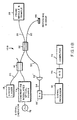
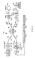
- FIG. 1A is a schematic block diagram of an optical coherence domain reflectometer in accordance with a preferred embodiment of the invention.
- FIG. 1B is a schematic block diagram of an alternative embodiment of the invention utilizing a frequency modulated optical source.
- FIG. 1C is a schematic block diagram of another fiber optic embodiment of the invention.
- FIG. 1D is a schematic block diagram of a bulk optic embodiment of the invention illustrating the use of two separate wavelengths to enhance resolution.
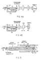
- FIG. 2A is a diagram of the envelope of a scan output which might be obtained utilizing the embodiments of FIG. 1 .
- FIG. 2B is an enlarged diagram of a portion of an output waveform such as that shown in FIG. 2A illustrating the modulation frequency on which such envelope is superimposed.
- FIG. 2C is a diagram of the waveform of FIG. 2B after demodulation.
- FIG. 3A is a block diagram illustrating one embodiment of a probe module to achieve multi-dimensional scanning.
- FIG. 3B is a diagram of an alternative probe module for performing two or three dimensional scanning.
- FIG. 3C is a diagram of an alternative probe module for achieving three dimensional scanning.
- FIG. 3D is a diagram of an alternative probe module for performing circular scanning.
- FIGS. 4A and 4B are diagrams of two additional probe module embodiments for performing multidimensional scanning.
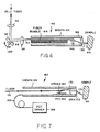
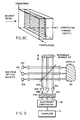
- FIG. 5 is a side sectional side diagrammatic view of one embodiment of an endoscopic probe module.
- FIG. 6 is a side sectional diagrammatic view of a second embodiment of endoscopic probe module.
- FIG. 7 is a side sectional diagrammatic view of a third embodiment of endoscopic probe module.
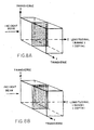
- FIG. 8A is a diagram illustrating a first scan pattern for two dimensional scanning of a sample in accordance with the teachings of this invention.
- FIG. 8B is a diagram illustrating a second scan pattern for two dimensional scanning of a sample in accordance with the teachings of this invention.
- FIG. 8C is a diagram illustrating a third scan pattern for two dimensional scanning of a sample in accordance with the teachings of this invention.
- FIG. 9 is a schematic block diagram of a parallel scanned embodiment.
- FIG. 10 is a schematic block diagram of a balanced receiver embodiment.
- FIG. 11 is a schematic block diagram of another fiber optic embodiment of the invention utilizing polarized light to detect birefringence.
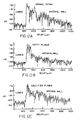
- FIGS. 12A-12C are diagrams obtained using an embodiment such as that shown in the figures to scan a human aorta which is normal, contains fatty plaque, and contains calcified plaque, respectively.
- an optical coherence domain reflectometer (OCDR) 10 which incorporates the teachings of this invention.
- the output from a short coherence length (broad spectral bandwidth) optical source 12 is coupled as one input to an optical coupler 14.
- Such coupling may be through a suitable optical path, which for the preferred embodiment is a fiber optic path 16.
- Source 12 may, for example, be a light emitting diode, super luminescent diode or other white light source of suitable wavelength, or may be a short-pulse laser.
- Such sources preferably having a coherence length of less than 10 micrometers for preferred embodiments. As will be discussed later, it is desirable that the coherence length of source 12 be minimized to enhance the resolution of the system.
- the other input to coupler 14 is from a laser 18 generating an optically visible output which is applied to the coupler through a fiber optic path 20.
- laser 18 does not contribute to the normal operation of the system and is utilized only to provide a source of visible light for proper alignment with a sample, when the light from diode 12 is in the infrared region and thus not visible.
- the output from coupler 14 is applied as an input to coupler 22 through fiber optic path 24.
- the light or optical energy received at coupler 22 is split between a first fiber optic path 26 leading to scanning/sample assembly 28 and a second fiber optic path 30 leading to a reference assembly 32.
- Assembly 28 may include a lens assembly formed of one or more lenses for focusing light received from optical path 26 on a sample to be scanned and various mechanisms for causing lateral, transverse or longitudinal motion of the light relative to the sample.
- longitudinal scanning is performed by movement at the reference assembly, it is also possible for the sample or probe to be moved longitudinally, or for longitudinal scanning to otherwise be performed at assembly 28.
- the assembly may also include a mechanism for controlling the longitudinal or depth position of the focus in conjunction with the longitudinal scan position.
- a probe module portion of assembly 28 may be designed for positioning adjacent to an outer surface of the sample, for example adjacent to a patient's eye for scanning and imaging or taking measurements on the patient's eye, or it may be adapted to be positioned inside the sample, being, for example, part of an angioscope or endoscope for scanning internal body or other channels.
- the sample being scanned and/or imaged is included in the assembly 28.
- FIGS. 3-7 Various mechanisms which may function as the assembly 28 in accordance with various embodiments of the invention are shown in FIGS. 3-7 .
- light transmitted by the probe to the sample is reflected by the sample back through the probe module to fiber 26.
- the optical fiber of path 26 may be wrapped around a piezoelectric crystal transducer or actuator 34 which vibrates (i.e. expands and contracts) in response to an applied electrical signal to cause slight expansion and contraction of the optical fiber and to thus modulate the optical signal passing through the fiber. As will be discussed later, this added modulation may facilitate detection.
- Reference assembly 32 may include a collimating lens 36, first and second acousto-optic modulators 38 and 40 (AOM 1 and AOM 2), a corner-cube retro-reflector 42 and an end mirror 44.
- corner cube 46 is mounted to a mechanism 46 which reciprocates the corner cube toward and away from both optical path 30 and end mirror 44 in a particular pattern to effect longitudinal scanning of the sample.
- the corner-cube is preferably moved at a uniform, relatively high velocity (for example greater than 1 CM/SEC), causing Doppler shift modulation used to perform heterodyne detection.
- the length or extent of movement of cube 42 by mechanism 46 is at least slightly greater than half the desired scanned depth range in the sample.
- the scanning pattern for mechanism 46 preferably has a uniform velocity V, at least during the portions thereof during which scanning occurs, and may, for example, be a ramp pattern, or a sawtooth pattern. With a ramp pattern, measurements or imaging would be taken on the ramp while with a sawtooth pattern at velocity V on both sides, scanning can be done with the corner cube moving in either one or both directions. Further, a sine wave or other scan pattern can be utilized with suitable compensation in other elements of the circuit.
- scanning in the longitudinal or depth dimension may be accomplished by reciprocating end mirror 44 with a suitable mechanism such as mechanism 46 rather than corner cube 42.
- a suitable mechanism such as mechanism 46 rather than corner cube 42.
- the effective stroke is reduced by 50% so that the end mirror 44 must be moved through a path which is slightly greater than the desired scan depth range rather than through a path equal to half such range.
- the greater travel stroke required for the mechanism 44 in this instance may adversely affect the scan rate achievable and may also limit the modulating Doppler shift frequency, requiring the use of additional modulating elements. If corner cube 46 is eliminated completely, the system becomes more susceptible to errors resulting from wobble of the end mirror as it is reciprocated.
- mechanism 46 moves a corner cube or end mirror at a velocity which, as indicated above, is substantially constant in the scanning range, for some embodiments to be discussed, Doppler shift modulation in the longitudinal direction is not utilized and movement of the mirror is effected primarily to control the desired scan depth. For such embodiments and others, mechanism 46 may operate in step fashion to control the desired scan depth.
- the total length of path 26 between coupler 22 and a selected depth point in a sample being scanned and the total length of path 30 between coupler 22 and end mirror 44, should be substantially equal for each depth point of the sample during a scan of selected depth range.
- the lengths of the optical fibers in paths 26 and 30 should also be substantially equal.
- the group velocity dispersion may be equalized by placing optical materials of known group velocity dispersion and thickness in the light paths to compensate for any inequality. For example, where the fiber in the reference path may need to be shorter than that in the sample probe, a length of high dispersion material may be included in the reference path. It is also important that the termination of the optical fibers utilized in this system be angle polished and/or anti-reflection coated to minimize reflections and maximize throughput.
- Mechanism 46 may be any one of a variety of devices adapted for performing the translation function.
- mechanism 46 could be a stepper motor, the motion of which is applied to corner-cube 42 or mirror 44 through an averaging mechanism for embodiments where uniform velocity is required.
- a DC servo-motor might also be utilized to obtain the desired motion.
- Various electromagnetic actuators for example a speaker coil, may also be utilized for this function. With such electromagnetic actuators, detection of mirror position and servo control thereof may be required in order to achieve uniform motion where required.
- a signal indicative of desired mirror position at each point in the mirror travel path could be compared against a signal from a detector of actual mirror position and any resulting error signals utilized to control the actuator to maintain the mirror moving at the desired constant velocity. It is also possible to use a servo-control galvanometer driven linear translator for the mechanism 46.
- Reflections received from assemblies 28 and 32 are applied through optical paths 26 and 30, respectively to optical coupler 22. These signals are combined in coupler 22, resulting in interference fringes for length-matched reflections, (i.e. reflections for which the difference in reflection path length is less than the source coherence length) and the resulting combined output is coupled onto fiber optic path 50.
- a polarization controller may be placed in one of the optical paths 26 or 30.
- a polarization controller 51 is shown in optical path 30 in FIG. 1A .
- Such a polarization controller compensates for changes in polarization in the fiber optic paths.
- polarization maintaining fibers and couplers may be utilized in the system to achieve the desired result.
- a polarization diversity receiver can be utilized in the system to eliminate signal fading. Such polarization diversity receivers are known in the art.
- the optical signal on fiber optic path 50 is applied to a photodetector 52 which converts the optical combined signal from path 50 to a corresponding current-varying electrical signal.
- the current-varying electrical signal on output line 54 from photodetector 52 is preferably converted to a voltage-varying signal by a transimpedance amplifier (TIA) 55 or other suitable means, the TIA output being applied as an input to a demodulator 56.
- TIA transimpedance amplifier
- demodulator 56 may consist of a bandpass filter 58 centered around the modulation frequency of the combined output signal and an envelope detector.
- the filter assures that only the signal of interest is looked at and removes noise from the output. This enhances the signal-to-noise ratio of the system and thus system sensitivity.
- the filtered signal is then applied to the envelope detector.
- the envelope detector in demodulator 56 may consist of a rectifier 62 and a subsequent low pass filter 64.
- the second filter removes any high frequency components from the base band signal.
- the demodulator may also include a logarithmic amplifier 66, either before or after the rectifier, for dynamic range compression. Where a logarithmic amplifier is not used, logarithmic compression may be performed elsewhere in the system, for example in the processing computer. Without logarithmic compression, strong reflections from boundaries would either be off scale or weaker reflections would not be visible.
- the exemplary demodulator described above is one type of heterodyne demodulator. However, a variety of other demodulation techniques known in the art may also be utilized to perform the demodulator function.
- the demodulated output from circuit 56 is the interferometric envelope signal of interest.
- a suitable printer 68 may be utilized to obtain a visual record of this analog signal which may be utilized by a doctor, engineer or other person for various purposes.
- the analog output from demodulator 56 is applied, either in addition to or instead of to printer 68, through an analog-to-digital converter 72 to a suitable computer 74 which is programmed to perform desired analysis thereon.
- One or more memory devices 74 may be provided with computer 72.
- Computer 72 may, for example, control the display of the demodulated signal on a suitable display device 76, such as a cathode ray tube monitor, or may control a suitable printer to generate a desired record.
- characteristics such as density of the scanned image may be reproduced utilizing gray scale levels (i.e. dark for high density and light for low density) or a "false color" image may be generated with the color from blue to red across the color spectrum being indicative of the characteristic.
- computer 72 may detect various points of interest in the demodulated envelope signal and may perform measurements or make other useful determinations based on such detections.
- Computer 72 may be a suitably programmed standard processor or a special purpose processor may be provided for performing some or all of the required functions.
- the OCDR shown in FIG. 1A may for some embodiment be utilized with corner cube 42 being scanned by mechanism 46 at an Intermediate but uniform velocity.
- an intermediate scanning velocity is considered one at which the Doppler frequency shift caused by cube or mirror movement is not negligible, but is low enough to fall within the predominant low frequency noise for the system.
- the noise spectrum includes noises arising from fluctuations in source 12, mechanical components and electrical circuits, and are larger at lower frequencies, typically below 10 kHz.
- High scan velocity is considered to be a velocity where the Doppler frequency shift is higher than the predominant low frequency noise.
- the Doppler shift frequency f D results from the translation of the cube 42 and, with a corner-cube, is given by the equation: f D ⁇ 4V/ ⁇ where V is the velocity at which the cube is being moved at the given time and ⁇ is the optical wavelength of the source. Where a corner-cube is not used, f D ⁇ 2V/ ⁇ .
- the corner-cube also doubles the Doppler shift frequency, and effective scanning stroke, for a given velocity V of the mechanism 46.
- this Doppler shift is less than the required bandwidth to overcome noise, including where stepped longitudinal or no longitudinal scanning is being performed so that the Doppler shift frequency is substantially zero
- additional modulation is needed to shift the modulation frequency above the predominant noise spectrum.
- this may be achieved by introducing sinusoidal phase modulation by use of piezoelectric transducer 34. While in FIG. 1A the additional modulation is introduced by use of the oscillator or transducer in sample path 26, such modulation could also be provided in the reference arm or path 30. Equivalent piezoelectric modulation of end mirror 44 could also be utilized. Further, in addition to piezoelectric transducer 34, the small movement required for this supplemental modulation may be achieved using electromagnetic, electrostatic, or other elements known in the art for providing small generally sine wave movements.
- this supplemental modulation can be achieved by passing light in the reference arm and/or sample arm through acousto-optic modulators (AOM's).
- AOM's acousto-optic modulators
- Such modulators produce a frequency shift of the light beam and thus produce an effect substantially equivalent to Doppler shifting the beam.
- Such acousto-optic modulators can, in some instances, be substituted for the movement of the mirror or corner cube.
- the AOM'S which can be bulk optical devices as shown in FIG. 1A or, may be smaller in-line optical fiber AOM's, effectively raise the carrier frequency to allow for high speed scanning. While one AOM may be adequate for this purpose, two AOM's can be used as shown in FIG. 1A . The reason for two AOM's is that since AOM's are normally driven at a much higher frequency then is required for this application, the detection frequency can be lowered to a desired frequency by driving two AOM's at different frequencies, the detector frequency being the difference frequency.
- Supplemental modulation from element 34, or from other suitable means which modulate the optical path length, is at a frequency f M and the oscillation amplitude of this modulator is adjusted so that the peak-to-peak oscillating movement or optical delay change is approximately one-half of the wavelength ⁇ of source 12.
- the combined effect of the supplemental modulation and the Doppler shift frequency causes the output envelope to be at modulating frequencies of f D , f M + f D , f M - f D and at higher harmonics of f M ⁇ f D .
- f M is normally chosen to be high enough to overcome noise spectrum and aliasing problems.
- Demodulation of the output from photodetector 54 is normally at f M +f D and/or f M -f D .
- demodulation is at f M +f D .
- the center frequency for bandpass filter 58 is thus set for the frequency (f M +f D ).
- the bandwidth for filter 58 should be approximately two to three times the full-width-half-maximum (FWHM) bandwidth of the received signal to avoid signal broadening and distortion.
- the bandwidth of low pass filter 64 would typically be roughly identical to that of bandpass filter 58.
- the scanning of cube 42 has been at constant velocity, at least through the scan interval.
- resonantly (sinusoidal) driven mechanical actuators can be used to drive cube 42 or mirror 44. These actuators can be galvanometrically or electrodynamically driven at the resonant frequencies of the mechanical actuator system and are commercially available. Adjustments to the system required to accommodate a sinusoidal drive are discussed later in conjunction with FIG. 1C .
- electro-optic techniques could be used in lieu of mechanical techniques to effect scanning.
- an acousto-optic modulator or other electro-optic modulator could be utilized to vary the light path.
- such devices are currently expensive and have limited range; such devices would therefore not be preferred for most applications.
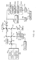
- FIG. 1B illustrates an alternate embodiment of the invention wherein longitudinal ranging information is obtained by optical frequency domain reflectometry rather than by optical coherence domain reflectometry.
- longitudinal ranging information is obtained by optical frequency domain reflectometry rather than by optical coherence domain reflectometry.
- the same reference numerals are utilized to identify common elements.
- a prime number may be utilized to identify a common element with a prior figure where the element has been slightly modified.
- FIG. 1B shows an optical frequency domain reflectometer utilizing a spectrally coherent optical source 79 which is frequency modulatable in one of a number of ways known in the art.
- Source 79 is frequency modulated in the form of a linear FM chirp by signal generator 78.
- the output from source 79 passes through the same optical paths described in conjunction with FIG. 1A to a sample assembly 28 and to a reference mirror 44. Since changes in optical path length are not being utilized for this embodiment of the invention to perform longitudinal scanning, the remainder of the reference assembly shown in FIG. 1A is not required nor are modulators 34, 38 and 40.
- a lens such as lens 36 may or may not be required.
- Reflected radiation from the sample in assembly 28 and from reference mirror 44 are combined in fiber optic coupler 22 and directed through optical path 50 to a wide bandwidth photodetector 52' where they optically interfere.
- Wide bandwidth photodetector 52' and transimpedence amplifier 55' are used to amplify the detected signal.
- the detected optical interference generates an RF frequency that is proportional to the differential path length between the sample reflection and the reflection from reference mirror 44.
- a variety of methods known in the art exist to convert this frequency information into spatial information in an electrical processor 81. These include using a waveform recorder with inverse Fourier transform techniques. Requirements on and techniques to achieve linearity, spectral coherence, modulation bandwidth and frequency deviation are all known in the art and such techniques can be employed in the embodiment of FIG.
- the output from processor 81 is digitized using A/D converter 70 and processed by computer 72 in the manner discussed in conjunction with FIG. 1A .
- Printers and displays may be provided for this embodiment of the invention as for the embodiment shown in FIG. 1A .
- the teachings of the invention may also be practiced employing a linearly chirped intensity modulated source.
- actuator 46 has a sinusoidal or other non-linear velocity profile
- the Doppler shift frequency f D is no longer constant, and the demodulator 56 must be adapted for this carrier frequency variation.
- an output line 87 is provided from a position sensor in the actuator 46.
- the reference assembly in this figure is shown as an end-mirror 44 moved longitudinally by an actuator 46'.
- the voltage on line 87 will normally vary as a function of actuator position and thus of position for mirror 44; however, the position sensor output may also be current varying. If the sensor provides a digital output, then line 87 may be connected to computer 72 without going through A/D converter 70'.
- the signal on line 87 is required when actuator 46' has a non-linear velocity profile so that intensity and other inputs received at computer 72 may be correlated with scan position in the sample. This correleation is not required with a linear scan where position can be determined from the time an input is received.
- the acceptance band for bandpass filter 58 and low pass filter 64 are increased to accommodate the variations in the Doppler shift frequency f D over a large portion of the sinusoidal motion of mirror 44. These variations occur because f D varies directly with variations in V. This increased demodulator acceptance bandwidth will lead to increased acceptance of noise and thus results in lower detection sensitivity.
- this technique is simple and can be used in cases where the requirement for detection sensitivity is not critical. Further, this increase in acceptance bandwidth may be relatively small when the signal bandwidth ⁇ f FWHM is already large relative to f D , this occurring when the coherent length is very small.
- FIG. 1C illustrates the second technique wherein the demodulation frequency is dynamically tuned to the instantaneous Doppler shift frequency using a superhetrodyne system.
- a sensor at actuator or drive mechanism 46' provides a velocity dependent voltage on line 89 which is modified by a gain circuit 91 and a bias circuit 93 before being applied to a voltage controlled oscillator 95.
- the output from oscillator 95 is multiplied in a circuit 97 with the output from detector 52 via amplifier 55.
- the gain and bias of the signal applied to VCO 95 are adjusted so that the modulating frequency at the output from multiplier 97 is substantially constant at a desired center frequency which is selected as the center frequency for bandpass filter 58.
- the bandwidth of filter 58 is set at two to three times the peak signal bandwidth and, except for the need for the position sensor output on line 87, the remainder of the detection and processing would be substantially identical to that previously described in conjunction with FIG. 1A .
- FIG. 1D shows a system 10D which is similar to that of FIG. 1A , except that bulk optics are utilized rather than fiber optics and ability to observe spatial properties is enhanced by providing two light sources 12A and 12B which are at different wavelengths. While the multiple wavelength option is being shown for purposes of illustration in conjunction with a bulk optics embodiment, it is to be understood that multiple wavelengths could also be, and may preferably be, used with the fiber optic embodiments. Sources 12A and 12B could be the same type of light sources designed to operate at different wavelengths or could be different types of light sources. The outputs from sources 12A and 12B are merged in a coupler 60, the optical output from which Is applied to a coupler 59.
- Couplers 60 and 59 could, for example, be dichoric beam splitters, polarization beam splitters or normal beam splitters.
- Coupler 59 The output from coupler 59 is applied to beam splitters 61 and 65.
- Beam splitter 61 applies a portion of its input through lens 36 to mirror 44 and also passes optical radiation to beam splitter 65 which applies this radiation through lens 82 to sample 84.
- Reflections from mirror 44 are applied through lens 36, beam splitter 61 and mirror 67 to interferometric coupler 69.
- Mirror 44 and lens 36 may be part of a translation stage which is moved by a mechanism such as the mechanism 46' discussed in conjunction with FIG. 1C .
- the output from coupler 69 may be applied to a CCD camera 71 used for alignment purposes and is also applied through a lens 73 to a photodetector 52.
- the output from the detector is applied through two separate paths.
- Each path contains a demodulator 56A, 56B containing a bandpass filter 58 having a center frequency which corresponds to the Doppler shift frequency f D for the given source 12. Since f D varies inversely as a function of the source wavelength, each demodulator only demodulates signals corresponding to the appropriate source wavelength, permitting outputs resulting from the two source wavelengths to be separated.
- the two outputs After being applied through corresponding A-D converters 70, the two outputs are applied to computer 72 where they may be appropriately processed.
- a detector 52 may be provided corresponding to each source wavelength, where each photodetector is preceded by an optical wavelength filter that only transmits the appropriate wavelength with an appropriate pass band.
- a beam splitter would be provided ahead of the optical wavelength filters, with a demodulator at the detector output.
- the sample 84 is the eye of a human or animal patient.
- the beam must be aligned with the sample so that it enters the sample at a desired angle. This angle is normally an angle perpendicular to the angle of the eye layers.
- the beam must be laterally positioned on the sample area of interest. This is a control of the lateral position of the beam.
- the beam must be focussed at the level of interest in the eye. A number of techniques may be utilized for performing each of these alignment functions.
- a number of different techniques may be utilized to obtain a desired incidence angle. Since reflections will generally be substantially maximized when the beam is normal to the layer or surfaces being reflected off of, one simple way to achieve alignment is to adjust the position or angle of the probe 80, of beam splitter 65, or lens 82 and/or of the sample (i.e., the patient's eye) and, with the reference arm blocked, detect reflections from the sample. The alignment at which the power of the detected reflections is maximum would thus be the desired alignment angle. it would normally be possible to locate the desired angle relatively quickly using this technique.
- a second technique for achieving angular alignment is similar to the first except that the reference arm is not blocked and, with normal readings being taken from the system, alignment is manually adjusted until an alignment which maximizes the output is obtained.
- a third method is to look at the direction in which the beam is reflected in order to detect beam alignment. Since it is hard to do this directly, particularly when a fiber is utilized, such determination is generally made by providing a beam splitter which directs a portion of the beam reflected from the sample to a device such as CCD camera 71 ( FIG. 1D ) which can measure beam position. This device is initially calibrated with the system so that the spot on which the beam impinges on the camera when the beam is properly aligned with a sample is determined. Then, in operation, the sample and probe can be adjusted until an angle of alignment is achieved where the beam impinges on the CCD camera at the previously determined point. Lateral position alignment is at this time best performed manually. To perform this operation, laser 18 is turned on.
- Source 12 may either be on or off for this operation.
- Laser 18 provides a narrow beam visual indication of the lateral position on the eye where the beam is striking and the position of either the probe beam or the patient may then be manually adjusted until the beam is striking the desired position. If light from source 12 is in a visible band, laser 18 may not be required and light from source 12 may be used for alignment.
- the focussing cone angle to be utilized for performing readings is determined by balancing the desirability of having as large a numerical aperture (cone angle) as possible against being able to achieve a desired longitudinal range or depth of field in which back scattered or reflected light is efficiently coupled back to the fiber (or to the other optical path 26 where a fiber is not employed).
- a large numerical aperture makes angular alignment for normal incidence on the sample surface less critical and for measurement of back scattering where the returned radiation is spread over wide solid angles, a wider cone angle increases the coupling into the fiber. However, the large cone angle reduces the longitudinal range.
- the numerical aperture or f number should be selected to correspond to a depth of field that is equal to the longitudinal extent of the area in the eye or other sample on which measurements are to be taken.
- depth of field is defined as the longitudinal distance from the focal plane at which the back coupling efficiency into the fiber is reduced by one-half.
- the sample and/or probe are moved relative to each other until the system is focussed to a desired point within the sample, i.e., within the eye. Since even with the laser it may be difficult to visually determine the focal point, a preferable way to perform focussing may be to operate the system with, for example, an output being obtained on display 76. As will be discussed later, certain high amplitude points in such output are indicative of a particular layer or transition in the eye and focus can be adjusted until this transition occurs at a desired point in the scan.
- the system may be utilized to take desired measurements. To perform such measurements, aiming laser 18 is turned off and source 12 is turned on. Mechanism 43 or 43' is also turned on, if not already on, to cause desired movement of the cube or mirror. If mechanism 43,43' is not moving at sufficiently high velocity, it may also be necessary to turn on piezoelectric modulator 34 or 63.
- source 12 should have a low coherence length which implies being spectrally wide.
- coherence length of approximately 10 micrometers
- spatial separation, and thus resolution, to 10 micrometers can be obtained. This is a far higher resolution than is available with other currently available devices.
- Path lengths 26 and 30 are initially equal with the beam focussed at a desired initial scan depth in sample 28.
- mirror 44 or cube 42
- the point in the sample at which the path lengths are equal is scanned to successively greater depths within the sample.
- reflections occur and light scattering occurs which are a function of the refractive index variation for the material through which the light is passing and of such index boundaries.
- Interference fringes occur for depth points in the sample where the difference between the path length to the point in the sample (L s ) and the path length to the current mirror location (L m ) differ by less than the coherence length (CL) of the light source (i.e. L s -L m ⁇ CL). Therefore, the coherence length of the light source determines available system resolution. This is the reason for keeping coherence length as low as possible.
- the interferometric output from coupler 22 or 69 is thus indicative of reflections or scattering obtained at a particular depth within the sample.
- the successive interferometric outputs obtained during a scan form an envelope signal such as that shown in FIG. 2A which normally has peaks at optical junctions within the samples where reflections are normally maximum and may have some lesser peaks in a predetermined pattern, depending on the scattering characteristics of the medium at the scan depth.
- a Doppler shift frequency having a frequency f D ⁇ 2V/ ⁇ , ( ⁇ 4V/2 for FIG. 1A where corner cube is moved) where V is the velocity at which the mirror is moved and ⁇ is the wavelength of source 12, is superimposed on the envelope signal as shown for a small portion of an intensity output in FIG. 2B.
- FIG. 2C shows this same output portion after demodulation.
- the Doppler shift frequency is dependent on the wavelength of source 12.
- the interferometric output from coupler 69 will contain two separate envelopes which are a function of the differences in absorption and reflection at the different wavelengths, and each interference output will be modulated at a different Doppler shift frequency.
- the bandpass filter 58 in each demodulator 56 may be selected to have a center frequency and bandwidth for a different one of the Doppler shift frequencies, or optical filtering with multiple detectors may be utilized, to permit detection and separation of these two signals.
- the ability to perform the interferometric detection at two or more different wavelengths offers unique advantages. These advantages arise from the fact that the absorption, reflection and other optical characteristics of various sample materials vary with wavelength. Thus, taking measurements at two or more wavelengths permits the spectral characterization of optical properties of the sample such as the wavelength dependent absorption and scattering thereof. In particular, the log rate of attenuation of back scatter is different for different materials and, for a given material, may vary with wavelength. By observing the back scatter pattern at different wavelengths from a substance, and possibly by observing the average rate of back scatter or reflection attenuation from layers of the sample, information concerning the material of the layer or various properties of such material may be obtained.
- spectral properties may be of interest in themselves and may also be used to distinguish between two sample layers, for example, two tissue layers that it is normally difficult to distinguish with single wavelength measurements because of their similar optical properties.
- ratios at each of the wavelengths spurious effects such as misalignment are compensated for permitting boundaries to be more easily and accurately identified. Basically, such boundaries are identified by looking at ratios rather than absolute values.
- FIG. 3A illustrates one relatively simple embodiment for the assembly 28 of FIGS. 1A-1B .
- fiber 26 terminates in a probe module 80.
- the probe module includes one or more imaging lenses, a single lens 82 being shown in the figure, positioned between the output of fiber 26 and the sample 84 being scanned.
- a suitable linear translation stage or other mechanism 86 is connected to move probe module 80 either transversely or laterally relative to the sample 84 to provide two-dimensional scanning.
- a similar mechanism (not shown) may be provided to move the probe in the other of the transverse or lateral direction to provide three-dimensional scanning of sample 84.
- Mechanism 86 may be a stepper motor or other suitable positioning mechanism and is preferably controlled either by computer 72 ( FIG. 1 ) or by a positioning computer which also provides positioning information to computer 72 so that the position of the scan on sample 84 is known by the computer. Further, as previously discussed, either probe module 80 or sample 84 may be moved in the longitudinal direction by a suitable translating mechanism to effect longitudinal position for scanning. This would be done in lieu of or in conjunction with moving the corner cube or end mirror.
- FIG. 3B shows another embodiment of the invention wherein the probe module includes a first collimating lens 90, a steering mirror 92 which may be rotated by a galvanometer or other suitable mechanism 100 about one or two axes in a plane sometimes referred to as the pupil plane, and two additional focusing lenses 94 and 96.
- the sample is illustrated as an eye 84'.
- focus is at or near the rear of eye 84' and the beam is pivoted about the nodal point of the eye at roughly the position of the ocular lens to scan different points along the rear surface of the eye as mirror 92 is rotated about pivot 98 and/or a pivot perpendicular thereto by mechanism 100.
- the position of mirror 92 would be communicated to computer 72 in a suitable manner.
- a scanning mechanism 104 is provided which is synchronized with scanning mechanism 46 and which moves focusing lens 90 in a direction parallel to the direction of the light passing therethrough. This causes a change in the focal depth for beam 102 in sample 84'.
- the focal point of beam 102 in eye 84' can be made substantially equal to the point being scanned in the eye at each point in time, providing optimum resolution for measuring and imaging.
- Other techniques known in the art for altering focal point in the longitudinal direction could also be utilized to synchronize the focal and detection points.
- FIG. 3B scanning is provided in one or two transverse dimensions in a single pupil plane.
- FIG. 3C shows an embodiment wherein two single-axes scanning mirrors are used, an additional scanning mirror 106 being provided in a second pupil plane, which mirror is scanned about a shaft 108 by a galvanometer or other suitable mechanism 110 in a direction perpendicular to the direction of rotation of mirror 92.
- Light reflected off of mirror 106 is passed through lenses 112 and 114 to pass through the aperture of eye 84' to a selected focal point in the eye, which point may be varied in three dimensions.
- the galvanometer-driven mirrors 92 and 106 in FIGS. 3B and 3C could be replaced by rotating polygonal mirrors or other angular beam steering devices.
- information concerning positions is communicated to computer 72 to permit proper imaging and processing.
- FIG. 3D shows still another embodiment of the assembly 28 wherein the mirror 92 in the pupil plane is rotated about a shaft 93 by a suitable rotary motion mechanism 95 and also has its pitch altered by a pitch altering mechanism 97.
- the mechanism of FIG. 3D may for example be utilized to scan around the optic nerve head of the patient's eye and this scan may be processed to provide a two-dimensional scan.
- mechanical steering mechanisms have been discussed above, electro-optic steering mechanisms known in the art could also be utilized.
- FIGS. 4A and 4B show still another embodiment for assembly 28 wherein fiber 26 is embedded in a sheath 101 which is attached to a stationary housing 105 through a pivot joint 103.
- Sheath 101 rests on a mechanism 107 fixed to housing 105 which mechanism may for example be a piezo-electric crystal, stepper motor, electro-magnetic actuator, electro-static actuator, or the like.
- mechanism 107 moves sheath 101, the tip of fiber 26 is moved transversely. This movement is converted by lenses to either an angular scan about a fixed entry point in eye 84' ( FIG. 4A ) and hence a transverse scan at the focal plane of the eye, or a transverse scan along a sample such as sample 84 ( FIG. 4B ).
- Lens 109 is shown as being movable longitudinally in FIG. 4B to either control longitudinal scanning or to synchronize the focusing in sample 84 with a longitudinal scan being performed in one of the manners mentioned previously in conjunction with FIGS. 1A-1B . If desired, pivot 103 may be eliminated so that sheath 101 moves straight up and down as a result of the operation of mechanism 107 rather than moving in an angular direction.
- FIG. 5 illustrates an alternative embodiment wherein the probe module is part of an angioscope or endoscope which may be utilized for imaging tubular structures 120 such as blood vessels, the esophagus, or the like.
- the distal end of fiber 26 is embedded in an inner sheath 122 which is rotatably mounted within an outer sheath 124.
- Inner sheath 122 has a lens 126 formed therein at the distal end of fiber 26 and terminates in an angled mirrored surface 128, which surface extends beyond the end of outer sheath 124.
- the probe module 121 may be moved laterally along vessel wall 120 (i.e.
- probe module 121 may move a substantial distance in the direction 130 along the vessel wall, in order to maintain the desired equal length for paths 26 and 30, fiber 26 may initially be provided with a certain amount of slack or may be curled or coiled to permit movement in this direction.
- the endoscope probe 140 shown in FIG. 6 has a lens 90 at the distal end of fiber 26, a galvanometer-controlled mirror 92 and a focusing lens 94 which function in the same way and perform substantially the same functions as the corresponding elements in FIG. 3B .
- Output beam 142 from lens 94 is applied to a selected one or more of the single-mode optical fibers in fiber optic bundle 144.
- the fiber of bundle 144 to which beam 142 is applied depends on the scan position of mirror 92.
- the output from the bundle 144 is passed through lenses 146 and 148 to sample 84.
- the transverse position of the scanning beam 150 on sample 84 varies with the fiber in bundle 144 to which beam 142 is applied and thus with the position of mirror 92. Beam 150 may thus be linearly scanned across sample 84 by the rotation of mirror 92. If mirror 92 is scanned in two dimensions, or if the output from lens 112 of the three-dimensional scanning mechanism of FIG. 3C is used instead of the output from lens 94, and fiber optic bundle 144 has fibers in two dimensions rather than in a single dimension, beam 150 may be scanned in a two-dimensional pattern across the surface of sample 84, permitting three-dimensional scanning to be performed.
- FIG. 7 shows still another endoscopic probe module 160 which may be constructed utilizing the teachings of this invention.
- the distal end of fiber 26 is connected by a spring 162 to the inner wall of sheath 124.
- Spring 162 rests on and is vibrated by a piezoelectric transducer 164, or other electromagnetic, electrostatic or other actuator known in the art, which is connected by electric cable 166 running along the wall of sheath 124 to a driver 168.
- Transverse motion of fiber 26 causes a corresponding transverse movement of light beam 170 which is applied to a graded refractive index lens (GRIN lens) or other suitable lens 172.
- the output light beam 174 from lens 172 provides a transverse scan of sample 84.
- GRIN lens graded refractive index lens
- FIGS. 5-7 While three different configurations of angioscopic/endoscopic probes are shown in FIGS. 5-7 , it is apparent that the teachings of this invention may be utilized to provide other angioscopic/endoscopic probe modules with either internal or external optics, with movement of either the fiber itself or of an external lens or mirror, and with varying scan patterns depending on application.
- a typical scan pattern for the various embodiments of the invention is for the probe assembly to be positioned at a selected transverse position with respect to the sample and mechanism 46 or other longitudinal scanning mechanism discussed in conjunction with FIGS. 1A-1B to be operated to complete the longitudinal or depth scan at the given transverse position.
- the transverse position is then altered in a manner, for example, described in conjunction with FIGS. 3-7 and a depth scan is completed at the new transverse position. This process is repeated until scanning has been performed at all desired transverse positions. This is the scan pattern illustrated in FIG. 8A .
- the scan pattern shown in FIG. 8A requires high velocity longitudinal scanning. As discussed above, for some embodiments this longitudinal scanning is preferably at a constant velocity in order to produce a uniform Doppler shift which can be demodulated in circuit 56 ( FIG. 1A ). However, very high speed constant velocity scanning is difficult to achieve. Therefore, since there is less of a requirement on constant velocity for transverse scanning, and since resonantly driven galvanometers or fiber deflectors can be used to produce very high rates of transverse scanning, a scan pattern such as that shown in FIG. 8B may be preferable, particularly when a large number of transverse points are being utilized for the image. In FIG. 8B , a complete transverse scan is performed for each longitudinal position. In other words, referring, for example, to FIG. 3A , mechanism 86 would perform a complete cycle for each position of mechanism 46 ( FIG. 1A ). With this scan pattern, mechanism 46 could be stepped rather than continuously slewed.
- FIG. 8C shows still another scan pattern which may be utilized in practicing the teachings of this invention.
- the longitudinal position in the sample is controlled using one of the techniques for longitudinal positioning previously discussed, for example by stepping the position of end mirror 44 to a selected position, and scanning is then performed at this depth or longitudinal position in the sample in one or two transverse dimensions. Once such a scan has been completed, the scan may either be repeated at the same depth or the longitudinal position control may be stepped to cause the subsequent scan to be performed at a different depth.
- this three-dimensional scan is similar to that of FIG. 8B except that scanning at each depth level is performed in two rather than one dimension and such two-dimensional scans may be performed at only one or more selected depths rather than at all selected depths.
- the scan pattern in the transverse dimensions need not be performed using straight lines. Curved or circular scan patterns may be used in instances where it is desired to obtain depth and cross-sectional image information along specific surfaces which are not curved.
- the scanning embodiments of FIGS. 3D and 5 illustrate this point.
- FIG. 9 illustrates an alternative embodiment of the invention wherein this problem is overcome by scanning the sample in parallel using multiple optical sources 12A-12C and multiple detectors 52A-52C, but a single movable reference mirror 44'. Separate optical sources may be provided for each source 12A-12C or optical radiation from one or more sources may be divided to provide the desired number of optical sources. Similarly, multiple references may be provided.
- the outputs from the multiple detectors 52A-52C are processed by a special processing circuit 180 before being applied to computer 72. Where a small number of parallel scans are being performed, it may still be necessary to also scan such sources laterally. For example, each of the beams applied to sample 84 in FIG. 9 could also be scanned in the direction in and out of the figure to provide three-dimensional scanning. Alternatively, parallel scanning could be performed in three dimensions. Assuming the capacity of electronic processing circuitry 180 is adequate, a large enough number of parallel scans in two or three dimensions could be provided so that additional lateral or transverse scanning of the beams is not required. Parallel scanning could also be performed utilizing the scan technique of FIG. 1B .
- a potential problem for embodiments having the transverse scanning patterns is that, with the high transverse scanning rates the embodiments require, the signal bandwidths being employed may be so great that signal aliasing may occur in an image.
- Signal aliasing involves variation in image intensity for a given image which may, for example, vary at the Doppler shift frequency (f D ).
- One way of compensating for such aliasing is to perform multiple scans on a single sample, to store the results of each scan in memory 74 and to average the values from the various scans in computer 72 to eliminate the aliasing variations.
- Other preferred ways of eliminating aliasing are to use one of the techniques previously described to obtain a modulation higher than the signal bandwidth.
- FIG. 11 illustrates the invention utilizing polarized light to detect birefringence.
- Light from light source 12 is polarized in a polarizer 190 sandwiched between a pair of lenses 192 before being applied to a polarization maintaining (high birefrigence) fiber 194.
- polarizer 190 is shown as vertically polarizing light from source 12, vertical polarization being one of the modes of fiber 194.
- Fiber 194 is connected to a polarization maintaining coupler 196 which outputs the vertically polarized light on polarization maintaining fibers 198 and 200.
- Fiber 198 terminates in a focussing lens 202, the optical output from which is applied through a quarter wave retardation plate 204 to sample 84'.
- Plate 204 is preferably a zero order or low order plate which is placed and oriented in a manner so that circularly polarized light is incident on sample 84'. In the absence of sample birefringence, plate 204 converts reflected light passing therethrough to fiber 198 into horizontal polarization. In the presence of sample birefringence which causes light to travel at different speeds through the layer depending on polarization, the light reflected from sample layers which are in, or deeper than, the birefringent sample structures will in general return to the fiber in elliptical polarization states.
- the vertically polarized light in fiber 200 is focussed by lens 202 and a quarter-wavelength retardation plate 210 to mirror 44.
- Plate 210 which is also preferably zero order or low order, is oriented in such a manner that light applied to the mirror is elliptically polarized and reflections from the mirror which are returned to fiber 200 are in a linear polarization state with equal horizontal and vertical components.
- the sample and reference reflections are recombined with interferometric fringes in coupler 196 and applied to a polarization maintaining fiber 212.
- Fiber 212 terminates in a lens 214 leading to a polarizing beam splitter 216, with horizontally polarized light from the beam splitter being applied to detector 52C and vertically polarized light from the beam splitter being applied to detector 52D.
- Lens 214 and polarizing beam splitter 216 may be replaced by a fiber polarizing beam splitter.
- the interferometric signals detected by the two detectors which signals are both at the same Doppler shift frequency, are separately processed in demodulators 56 and A/D converters 70 (the separate demodulators and A/D converters being shown for simplicity as single units in FIG. 11 ) to produce two interferometric signals, a horizontal amplitude component I1 and a vertical amplitude component I2.
- I I 1 2 + I 2 2
- Birefringence is observed in structures in the eye such as the nerve fiber layer of the retina, as well as in other highly ordered biological tissues, crystals and other structures. Changes in eye nerve fiber layer thickness of 10-20 micrometers may be significant interval changes in glaucoma, and may presage the development of optic nerve head cupping and other visual field loss. Prior art techniques for measuring retinal thickness have only had a resolution on the order of 40 micrometers. However, the apparatus shown in FIG. 11 can detect the thickness of the birefringent retinal nerve fiber layer with a resolution of 10 microns.
- Back scattering from inside the retinal nerve fiber layer RNFL
- RNFL Back scattering from inside the retinal nerve fiber layer
- the range of depth over which the birefringent retardation is changing is the thickness of the RNFL and the rate of change of birefringent retardation (total retardation divided by the thickness of the RNFL) can provide a measure of the nerve axon density inside the RNFL.
- the back scattering and reflections from layers deeper than the RNFL will acquire a constant amount of birefringent retardation.
- FIGS. 12A-12C are illustrations of back scattering patterns obtained from an arterial wall which is normal and which has various types of plaque deposited thereon. The log rate of attenuation for back scatter is also different for fatty plaque than for arterial wall, providing an additional way of distinguishing plaque.
- a fiber optic probe of the type shown in FIGS. 5-7 could be delivered by use of an endoscope to a desired site to provide high resolution images for use in laser angioplasty and lithotripsy. This would enhance the usability of such procedures by reducing the dangers of unintentional vessel damage and rupture.
Landscapes
- Health & Medical Sciences (AREA)
- Life Sciences & Earth Sciences (AREA)
- Physics & Mathematics (AREA)
- General Physics & Mathematics (AREA)
- General Health & Medical Sciences (AREA)
- Surgery (AREA)
- Engineering & Computer Science (AREA)
- Molecular Biology (AREA)
- Heart & Thoracic Surgery (AREA)
- Biophysics (AREA)
- Pathology (AREA)
- Biomedical Technology (AREA)
- Medical Informatics (AREA)
- Animal Behavior & Ethology (AREA)
- Public Health (AREA)
- Veterinary Medicine (AREA)
- Radiology & Medical Imaging (AREA)
- Nuclear Medicine, Radiotherapy & Molecular Imaging (AREA)
- Optics & Photonics (AREA)
- Chemical & Material Sciences (AREA)
- Nanotechnology (AREA)
- Signal Processing (AREA)
- Analytical Chemistry (AREA)
- Biochemistry (AREA)
- Immunology (AREA)
- Ophthalmology & Optometry (AREA)
- Crystallography & Structural Chemistry (AREA)
- Spectroscopy & Molecular Physics (AREA)
- Investigating Or Analysing Materials By Optical Means (AREA)
- Length Measuring Devices By Optical Means (AREA)
- Instruments For Measurement Of Length By Optical Means (AREA)
- Endoscopes (AREA)
- Eye Examination Apparatus (AREA)
Abstract
Description
- This invention relates to optical imaging, including utilizing such images to perform precision measurements on biological and other samples.
- There are many industrial, medical, and other applications where high resolution (generally less than 10 micrometer) images of, and measurements of distances, thicknesses, and optical properties of, a biological or other sample are required.
- Existing techniques for performing such measurements include optical coherence domain reflectometers (OCDR), optical time domain reflectometry (OTDR), ultrasound, scanning laser microscopes, scanning confocal microscopes, scanning laser ophthalmoscopes and optical triangulation. Existing OCDR systems do not normally have the rapid data acquisition rate required for the measurement of biological or other samples having the potential for dynamic movement; while OTDR systems are very expensive and have only limited resolution and dynamic range.
- Ultrasound, which is perhaps the most commonly used technique, is disadvantageous for applications such as taking measurements on the eye in that, in order to achieve the required acoustic impedence matches, and to thus avoid beam losses and distortion, contact is generally required between the ultrasonic head or probe and the product or patient being scanned. While such contact is not a problem when scans are being performed on, for example, a patient's chest, such probes can cause severe discomfort to a patient when used for taking eye measurements such as those used for measuring intraocular distances for computing the power of lens implants.
- The relatively long wavelengths employed in ultrasound also limit spatial resolution. Further, ultrasound depends on varying ultrasound reflection and absorption characteristics to differentiate and permit recording or display of tissue, or other boundaries of interest. Therefore, when the acoustic characteristics of adjacent layers to be measured are not significantly different, ultrasound may have difficulty recognizing such boundaries.
- Scanning laser or confocal microscopes and scanning laser ophthalmoscopes (SLO) provide highly spatially resolved images, for example being able to gnerate real time video images of the eye with a lateral resolution of a few micrometers. However, the depth resolution of SLO's quickly degrade with decreasing numerical aperture. For example, SLO measurements of the retina through the pupil aperture restrict the depth resolution to roughly 200 microns. SLO's are also expensive, costing in the range of a quarter million dollars.
- Optical triangulation offers fairly high resolution, but requires parallel boundaries. Such devices also have relatively poor signal-to-noise ratios and have degraded resolution at greater depths, where numerical aperture is restricted.
- In
DE-A1-2528209 an interferometer for surface profilometry is disclosed, with which the object to be measured is arranged in the measurement beam path of the interferometer and a reference reflector is arranged in a reference beam path. The reference reflector is periodically moved along the direction of the reference beam path and the position of the reference mirror in which interference occurs between light reflected at the reference reflector and light reflected at the object surface is a measure for the position of the object surface in the direction of the measuring beam path. - This known apparatus does not provide the possibility to perform high resolution measurements of distances or thicknesses between or of sample layers of for example biological samples such as an eye.
-
DE-A1-3201801 discloses an apparatus for measuring distances in a living eye. The eye is illuminated and the light reflected at different layers of the eye is visually observed through an interferometer with which the length of one beam path can be changed. Interference between light reflected at different layers occurs if the path length difference within the eye is compensated by a respective path length difference within the interferometer. - However, if the distances of different layers within the eye are the same or nearly the same such layers cannot be distinguished since the respective interferences occur at the same path length difference within the interferometer.
-
GB-A-21 91 855 - An Optical coherence tomograph allowing cross sectional imaging of biological systems is described in Huang et al., "Optical coherence tomography", Science, Vol. 254, 22 November 1991, p.1178-1181. An scanning interferometer which utilizes two-wavelengths is disclosed in den Boef, "Two-wavelength scanning spot interferometer using single-frequency diode Lasers", Applied Optics, Vol. 27, No. 2, 15 January 1998, p. 306-309.
- A need, therefore, exists for an improved method and apparatus for performing high resolution measurements and in particular for optically performing such measurements, which improved technique does not require contact with the body being measured, which maintains substantially constant high resolution over a scanning depth of interest, regardless of available aperture size and which is relatively compact and inexpensive to manufacture. Such a system should also be capable of providing differentiation between sample layers, should be able to provide identification of layer material or of selected properties thereof, should be able to provide one, two and three-dimensional images of a scanned body and should be rapid enough for use in biological and other applications where the sample being measured changes over relatively short time intervals. Finally, it would be desirable if such technique could also provide information concerning the birefringence property and spectral properties of the sample.
- More specifically, a need exists for a means to perform scanning of a sample in at least one transverse direction at a selected longitudinal depth, with the capability of also scanning in the longitudinal direction. Further, particularly in medical application, it is frequently desirable to provide such scans inside of tubular or other structures such as blood vessels, the bronchial tree of the lungs, the gastrointestinal tract, the genital tract or the urinary tract, using an angioscope or endoscope. In order for such scanning to be performed, a probe must be provided which is capable of being mounted in an endoscope or angioscope for performing internal scans.
- While typically a scan would be completed through the full depth range at a given lateral and/or transverse position before repositioning to the next position, this may require scanning of the mirror or other element used for performing longitudinal range or depth scans at a rate higher than the capacity of existing equipment. This is particularly true where the longitudinal scan produces a Doppler shift frequency which affects the interferometric signal frequency and hence the system sensitivity. It is, therefore, desired that such scanning be performed at a constant velocity. However, since very high speed longitudinal scanning at a constant velocity is difficult to achieve, where two or three dimensional scanning is being performed, other scan patterns may be required. Further, in some applications, it may be desirable to perform transverse scanning in one or two dimensions at a selected longitudinal position or depth.
- Another problem which becomes particularly serious when transverse scanning is being performed is that the bandwidth of the received signals increases beyond the inherent Doppler frequency shift of the system. In such cases, aliasing (i.e. variations in image intensity) may occur. It is, therefore, desirable that a technique be provided to enhance resolution by eliminating or averaging out such intensity variations.
- Another problem with the prior system is that, if scanning is to be conducted over an extended depth range, a smaller numerical aperture must be used so as to extend the depth of focus. However, this reduces lateral resolution and the received optical signal power throughout the range. A need, therefore, exists for a technique which permits the use of a large numerical aperture over an extended depth range within a sample.
- Further, some of the problems described which result from performing longitudinal scanning by mechanically moving a mirror or other element may be overcome by performing this scan electronically, for example by varying the optical frequency or amplitude of the light incident from the light source. However, for certain applications, for example imaging a dynamic biological sample such as the eye, the scanning speed required to do three-dimensional scanning may be such that a parallel scanning technique may be preferable or may be required.
- Thus, a need exists for improved optical coherence domain reflectometer (OCDR) optical imaging and measurement systems or for other imaging and measurement systems, particularly electronically scanned systems, which are capable of performing one, two and three dimensional scans and measurements at a selected and/or over an extended longitudinal or depth range for either internal or external samples with sharp focus and high resolution and sensitivity over the range.
- At least some of the above problems are solved according to the invention by an apparatus comprising the features of claim 1 or 13. Further advantageous embodiments of the invention comprise the features of the dependent claims.
- In accordance with the above, this invention provides a method and apparatus for performing optical imaging and measurements on a sample by applying optical radiation, which radiation has a short coherence length for preferred embodiments, to a reference optical reflector and to the sample through first and second optical paths respectively. The optical paths are preferably fiber optic paths. The longitudinal range within the sample from which imaging information is obtained is controlled by, for example, altering the relative lengths of the paths or by varying the frequency or intensity of the source in accordance with a predetermined profile. The lateral or transverse position on the sample at which imaging or measurements are being performed may also be selectively changed. This can result in imaging being performed on the sample in at least one transverse dimension. Where the profile for longitudinal scanning is a steppable profile, transverse scanning in one or two dimensions may be performed at any selected longitudinal range. Reflections from the reflector through the first optical path and reflections from the sample received through the second optical path are combined, the resulting combined optical output having interference fringes at matched points, for example, length matched points, on the two paths and having an instantaneous modulating frequency which may include a Doppler shift frequency at a frequency fD~NV/λ for embodiments where relative path lengths are being altered with a velocity profile having an instantaneous velocity V at each point on the profile. The combined output is detected and the detected output is processed to obtain a selected image of the sample and/or information concerning selected measurements.
- For embodiments where V is to be substantially constant over the scan range, the changes in first path length may be ramped, with the change in one direction occurring at the velocity V and the change in the other direction occurring much more rapidly. The changes in first path length may also have a triangular pattern, with the change in at least one direction being at the velocity V. The scan pattern may also be a sinusoidal pattern. With uniform velocity, measurements would be taken during a translation which occurs at the velocity V and may occur for path length changes in both directions with a triangular drive. With a sinusoidal drive, the nonlinearity may be detected and taken into account in subsequent processing.
- The system is preferably implemented utilizing optical fibers in the optical paths; however, the system may also be implemented utilizing bulk optics or other optical components. Where optical fibers are employed, the lengths of the paths and the lengths of the fibers in the paths are preferably both substantially equal.
- The changes in the first optical path are preferably accomplished by reciprocating the mirror or other reference reflector in a direction substantially perpendicular to the optical path. A suitable means may be provided for maintaining the reflector in alignment in spite of movement and wobble of the reflector as it is moved. The numerical aperture for the coupling to the sample should also correspond to a depth field equal to a predetermined depth extent within the sample over which measurements are to be taken.
- For measurements on at least one birefringent layer, the system includes a means for polarizing the optical energy from the source in a selected first direction, the polarization of the light being altered differently for energy applied to the reflector and to the sample. The elements which alter the polarization also cause reflected light energy from the reflector to be polarized in a second selected direction and cause reflected light energy from the sample to be polarized in a direction dependent on the birefrigence of the birefringent sample. The combined outputs containing interferometric fringes are split and detected as two outputs having orthogonal polarizations. These two outputs are then separately processed to obtain separate interferometric signals and the separate interferometric signals are combined to provide selected indications of birefringence.
- In order to enhance the ability of the system to distinguish a boundary between layers having similar optical properties, and to obtain other information concerning such layers, advantage is taken of the fact that the optical absorption, impedance, and other optical characteristics of materials may vary with wavelength. Thus, one layer of a junction may be more easily detected at a first wavelength of the optical energy, while another layer may be more easily detected at a different wavelength. For one embodiment of the invention, two or more short coherence length optical sources provide optical radiation at different wavelengths, for example λ1 and λ2, the sample reacting differently to inputs received at these different wavelengths. This results in a first interferometric optical output modulated at a frequency fD1=2V/λ1 and a second interferometrical optical output modulated at a frequency fD2=2V/λ2. The two outputs are separately demodulated and may then be separately processed or processed together.
- The second optical path is terminated in a probe module which preferably includes a means for controlling the transverse position on the sample at which imaging and/or measurement are being performed, and a means for selectively changing this position in at least one dimension to scan the sample. The velocity V may be sufficiently high so that the Doppler shift frequency is sufficiently high to meet the bandwidth requirements to overcome the predominate low frequency noise for the system and for signal aliasing. Where this is not the case, a means is provided for causing a vibratory or other change in a modulating frequency fM, resulting in a modulating frequency which is a selected combination of fD and fM. This change may be effected by a piezoelectric transducer or by at least one acousto-optic modulator (AOM) in at least one of the optical paths. For one embodiment, there are two AOM's in one of the optical paths, with fM being the difference frequency shift caused by the two AOM's. The probe position controller may include means for moving a probe at the end of the second optical path or the distal end of a fiber optic element forming the second optical path in at least one dimension substantially perpendicular to the direction in which optical radiation is applied to the sample to provide two-dimensional or three-dimensional scanning of the sample.
- For other embodiments, the probe module may include mirrors or other means for steering the optical radiation to a position on the sample and for optically changing the transverse position in at least one dimension, generally perpendicular to the direction in which the optical radiation is applied to the sample. Where three dimensional scanning is desired, the transverse position is changed in two directions. The means for optically changing transverse position may include at least one movable mirror in the optical path of the radiation for angularly translating the radiation at an angle dependent on mirror position. One mirror may be movable in two orthogonal directions to angularly translate the radiation in a direction which varies in two dimensions, whereby three dimensional scanning is achieved, or this objective may be achieved utilizing two mirrors successively spaced along the optical path, with the mirrors being movable in different, generally orthogonal, directions.
- For other embodiments, the probe module is a mechanism for scanning internal channels such as an angioscope or endoscope. For such applications, the probe module may include an outer sheath. For one embodiment, the probe module also includes an inner sheath rotatably mounted within the outer sheath, an optical means for directing radiation from the second optical path through the inner sheath, and a means movable with the inner sheath for directing the radiation at a selected position on the internal channel, the selected position varying as the inner sheath is rotated. This embodiment preferably uses a mirror mounted to rotate with the inner sheath to reflect radiation passing through the inner sheath in a selected direction beyond the end of the outer sheath.
- For another embodiment, a bundle of optical fibers is mounted in the outer sheath. A first end of a selected one or more of such optical fibers are optically connected to the second optical path, a means being provided for controlling the optical fiber(s) to which the second optical path is connected. There is also a means for establishing a selected transverse position on the sample for each of the optical fibers and for optically connecting a second end of each optical fiber to the corresponding selected transverse position.
- For still another embodiment, wherein the first and second optical paths are in the form of first and second optical fibers respectively, the probe includes a means for securing a distal end of the second optical fiber to an inner wall of the sheath. This means includes means for moving the distal end toward and away from the wall. Means are also provided for optically connecting the distal end of the fiber to the sample, this means establishing a selected focal position on the sample for each position of the distal end relative to the wall.
- For some embodiments, the probe module includes a means for controlling the focus for the module in the sample so that this depth focus is maintained substantially at a point in the sample from which imaging information is being obtained as this point is periodically changed during a longitudinal scan of the sample. Such focal plane may be accomplished by moving a focusing lens of the probe module in the direction of the radiation passing therethrough to control focus depth.
- Multi-dimensional scanning may be accomplished utilizing at least three different scan patterns. For one scan pattern, the rates at which the relative lengths of the optical paths are altered and at which the transverse position on the sample is changed are such that points at all longitudinal ranges of interest are scanned for a given sample transverse position before the scan beam is moved to initiate imaging at a new transverse position. Alternatively, the relative rates at which the longitudinal range altering and sample transverse position changing occur may be such that all imaging positions in at least one transverse dimension are scanned at a given longitudinal range in the sample before the longitudinal range is altered to cause scanning at a new range to be performed. The latter scanning procedure may be desirable where very high speed, uniform velocity longitudinal scanning would be required if the first scanning pattern were utilized. A third scanning pattern is to step the longitudinal position control to a selected longitudinal position and to then perform scanning in one or two dimensions at such longitudinal positions.
- For some embodiments, a plurality of optical paths may be provided to permit parallel scanning on the sample. In addition, for some embodiments a characteristic of the optical source, such as its frequency or intensity is controlled or varied to control the longitudinal point in the sample being imaged, the received reflections resulting in an output having a frequency proportional to the optical length of the path to the longitudinal point or plane in the sample being imaged at the time. This output is detected and processed to obtain the image.
- Because of aliasing or other problems, spurious intensity variations may occur in an image produced as a result of a two or three dimensional scan. To overcome this problem, AOM's may be used as previously indicated or a plurality of scans may be performed on a sample, with the scans being averaged to compensate for intensity variations.
- For preferred embodiments, the measurements involve non-invasive cross-sectional imaging in and measurements on biological specimens. One particular useful application for the invention is in producing cross-sectional images of various eye sections.
- The foregoing and other objects, features and advantages of the invention will be apparent from the following more particular description of preferred embodiments of the invention as illustrated in the accompanying drawings.
-
FIG. 1A is a schematic block diagram of an optical coherence domain reflectometer in accordance with a preferred embodiment of the invention. -
FIG. 1B is a schematic block diagram of an alternative embodiment of the invention utilizing a frequency modulated optical source. -
FIG. 1C is a schematic block diagram of another fiber optic embodiment of the invention. -
FIG. 1D is a schematic block diagram of a bulk optic embodiment of the invention illustrating the use of two separate wavelengths to enhance resolution. -
FIG. 2A is a diagram of the envelope of a scan output which might be obtained utilizing the embodiments ofFIG. 1 . -
FIG. 2B is an enlarged diagram of a portion of an output waveform such as that shown inFIG. 2A illustrating the modulation frequency on which such envelope is superimposed. -
FIG. 2C is a diagram of the waveform ofFIG. 2B after demodulation. -
FIG. 3A is a block diagram illustrating one embodiment of a probe module to achieve multi-dimensional scanning. -
FIG. 3B is a diagram of an alternative probe module for performing two or three dimensional scanning. -
FIG. 3C is a diagram of an alternative probe module for achieving three dimensional scanning. -
FIG. 3D is a diagram of an alternative probe module for performing circular scanning. -
FIGS. 4A and 4B are diagrams of two additional probe module embodiments for performing multidimensional scanning. -
FIG. 5 is a side sectional side diagrammatic view of one embodiment of an endoscopic probe module. -
FIG. 6 is a side sectional diagrammatic view of a second embodiment of endoscopic probe module. -
FIG. 7 is a side sectional diagrammatic view of a third embodiment of endoscopic probe module. -
FIG. 8A is a diagram illustrating a first scan pattern for two dimensional scanning of a sample in accordance with the teachings of this invention. -
FIG. 8B is a diagram illustrating a second scan pattern for two dimensional scanning of a sample in accordance with the teachings of this invention. -
FIG. 8C is a diagram illustrating a third scan pattern for two dimensional scanning of a sample in accordance with the teachings of this invention. -
FIG. 9 is a schematic block diagram of a parallel scanned embodiment. -
FIG. 10 is a schematic block diagram of a balanced receiver embodiment. -
FIG. 11 is a schematic block diagram of another fiber optic embodiment of the invention utilizing polarized light to detect birefringence. -
FIGS. 12A-12C are diagrams obtained using an embodiment such as that shown in the figures to scan a human aorta which is normal, contains fatty plaque, and contains calcified plaque, respectively. - Referring first to
FIG. 1A , an optical coherence domain reflectometer (OCDR) 10 is shown which incorporates the teachings of this invention. In particular, the output from a short coherence length (broad spectral bandwidth)optical source 12 is coupled as one input to anoptical coupler 14. Such coupling may be through a suitable optical path, which for the preferred embodiment is afiber optic path 16.Source 12 may, for example, be a light emitting diode, super luminescent diode or other white light source of suitable wavelength, or may be a short-pulse laser. Such sources preferably having a coherence length of less than 10 micrometers for preferred embodiments. As will be discussed later, it is desirable that the coherence length ofsource 12 be minimized to enhance the resolution of the system. - The other input to
coupler 14 is from alaser 18 generating an optically visible output which is applied to the coupler through afiber optic path 20. As is discussed in greater detail later,laser 18 does not contribute to the normal operation of the system and is utilized only to provide a source of visible light for proper alignment with a sample, when the light fromdiode 12 is in the infrared region and thus not visible. - The output from
coupler 14 is applied as an input tocoupler 22 throughfiber optic path 24. The light or optical energy received atcoupler 22 is split between a firstfiber optic path 26 leading to scanning/sample assembly 28 and a secondfiber optic path 30 leading to areference assembly 32.Assembly 28 may include a lens assembly formed of one or more lenses for focusing light received fromoptical path 26 on a sample to be scanned and various mechanisms for causing lateral, transverse or longitudinal motion of the light relative to the sample. In particular, while for the preferred embodiment longitudinal scanning is performed by movement at the reference assembly, it is also possible for the sample or probe to be moved longitudinally, or for longitudinal scanning to otherwise be performed atassembly 28. The assembly may also include a mechanism for controlling the longitudinal or depth position of the focus in conjunction with the longitudinal scan position. A probe module portion ofassembly 28 may be designed for positioning adjacent to an outer surface of the sample, for example adjacent to a patient's eye for scanning and imaging or taking measurements on the patient's eye, or it may be adapted to be positioned inside the sample, being, for example, part of an angioscope or endoscope for scanning internal body or other channels. For purposes ofFIG. 1A , the sample being scanned and/or imaged is included in theassembly 28. Various mechanisms which may function as theassembly 28 in accordance with various embodiments of the invention are shown inFIGS. 3-7 . - For all embodiments, light transmitted by the probe to the sample is reflected by the sample back through the probe module to
fiber 26. The optical fiber ofpath 26 may be wrapped around a piezoelectric crystal transducer oractuator 34 which vibrates (i.e. expands and contracts) in response to an applied electrical signal to cause slight expansion and contraction of the optical fiber and to thus modulate the optical signal passing through the fiber. As will be discussed later, this added modulation may facilitate detection. -
Reference assembly 32 may include acollimating lens 36, first and second acousto-optic modulators 38 and 40 (AOM 1 and AOM 2), a corner-cube retro-reflector 42 and anend mirror 44. For the preferred embodiment,corner cube 46 is mounted to amechanism 46 which reciprocates the corner cube toward and away from bothoptical path 30 andend mirror 44 in a particular pattern to effect longitudinal scanning of the sample. As discussed in greater detail later, the corner-cube is preferably moved at a uniform, relatively high velocity (for example greater than 1 CM/SEC), causing Doppler shift modulation used to perform heterodyne detection. The length or extent of movement ofcube 42 bymechanism 46 is at least slightly greater than half the desired scanned depth range in the sample. The scanning pattern formechanism 46 preferably has a uniform velocity V, at least during the portions thereof during which scanning occurs, and may, for example, be a ramp pattern, or a sawtooth pattern. With a ramp pattern, measurements or imaging would be taken on the ramp while with a sawtooth pattern at velocity V on both sides, scanning can be done with the corner cube moving in either one or both directions. Further, a sine wave or other scan pattern can be utilized with suitable compensation in other elements of the circuit. - Alternatively, scanning in the longitudinal or depth dimension may be accomplished by reciprocating
end mirror 44 with a suitable mechanism such asmechanism 46 rather thancorner cube 42. However, if this is done, the effective stroke is reduced by 50% so that theend mirror 44 must be moved through a path which is slightly greater than the desired scan depth range rather than through a path equal to half such range. The greater travel stroke required for themechanism 44 in this instance may adversely affect the scan rate achievable and may also limit the modulating Doppler shift frequency, requiring the use of additional modulating elements. Ifcorner cube 46 is eliminated completely, the system becomes more susceptible to errors resulting from wobble of the end mirror as it is reciprocated. - It is also possible to eliminate the end mirror by arranging the corner cube for a single pass configuration. In this configuration, incoming light to the corner cube is aligned with the corner cube vertex. This also results in a 50% decrease in the effective stroke. In addition, as discussed above,
mechanism 46 may be eliminated in thereference assembly 32, with longitudinal scanning being performed inassembly 28 by moving either the probe or sample in the longitudinal direction. This will be discussed later. If this is done, then cornercube 42 is not required and light frompath 30 may inpinge directly onmirror 44. - Finally, while for preferred embodiments utilizing a Doppler shift frequency,
mechanism 46 moves a corner cube or end mirror at a velocity which, as indicated above, is substantially constant in the scanning range, for some embodiments to be discussed, Doppler shift modulation in the longitudinal direction is not utilized and movement of the mirror is effected primarily to control the desired scan depth. For such embodiments and others,mechanism 46 may operate in step fashion to control the desired scan depth. - The total length of
path 26 betweencoupler 22 and a selected depth point in a sample being scanned and the total length ofpath 30 betweencoupler 22 andend mirror 44, should be substantially equal for each depth point of the sample during a scan of selected depth range. In addition, to prevent group velocity dispersion which would decrease spatial resolution, the lengths of the optical fibers inpaths -
Mechanism 46 may be any one of a variety of devices adapted for performing the translation function. For example,mechanism 46 could be a stepper motor, the motion of which is applied to corner-cube 42 ormirror 44 through an averaging mechanism for embodiments where uniform velocity is required. A DC servo-motor might also be utilized to obtain the desired motion. Various electromagnetic actuators, for example a speaker coil, may also be utilized for this function. With such electromagnetic actuators, detection of mirror position and servo control thereof may be required in order to achieve uniform motion where required. More specifically, in a uniform motion system, a signal indicative of desired mirror position at each point in the mirror travel path could be compared against a signal from a detector of actual mirror position and any resulting error signals utilized to control the actuator to maintain the mirror moving at the desired constant velocity. It is also possible to use a servo-control galvanometer driven linear translator for themechanism 46. - One potential problem in the
reference mechanism 32 is wobble of the mirror being translated which may adversely effect the accuracy of distance determinations. Such wobble is partially compensated for in the embodiment ofFIG. 1A by corner-cube 42, such corner cubes generally having the property that, regardless of the angle at which a beam is incident thereon, the beam will always return in exactly the same direction at which the beam was incident. Other techniques known in the art may also be utilized to deal with the wobble problem. - Reflections received from
assemblies optical paths optical coupler 22. These signals are combined incoupler 22, resulting in interference fringes for length-matched reflections, (i.e. reflections for which the difference in reflection path length is less than the source coherence length) and the resulting combined output is coupled ontofiber optic path 50. - To maximize interference between light returning from the reference and sample optical paths, their polarization should be substantially the same. To accomplish this polarization matching, a polarization controller may be placed in one of the
optical paths polarization controller 51 is shown inoptical path 30 inFIG. 1A . Such a polarization controller compensates for changes in polarization in the fiber optic paths. Alternatively, polarization maintaining fibers and couplers may be utilized in the system to achieve the desired result. Further, in applications where polarization is randomly varying, a polarization diversity receiver can be utilized in the system to eliminate signal fading. Such polarization diversity receivers are known in the art. - The optical signal on
fiber optic path 50 is applied to aphotodetector 52 which converts the optical combined signal frompath 50 to a corresponding current-varying electrical signal. The current-varying electrical signal onoutput line 54 fromphotodetector 52 is preferably converted to a voltage-varying signal by a transimpedance amplifier (TIA) 55 or other suitable means, the TIA output being applied as an input to ademodulator 56. - Various forms of demodulation may be utilized in practicing the teachings of this invention. In its simplest form,
demodulator 56 may consist of abandpass filter 58 centered around the modulation frequency of the combined output signal and an envelope detector. The filter assures that only the signal of interest is looked at and removes noise from the output. This enhances the signal-to-noise ratio of the system and thus system sensitivity. The filtered signal is then applied to the envelope detector. - The envelope detector in
demodulator 56 may consist of arectifier 62 and a subsequentlow pass filter 64. The second filter removes any high frequency components from the base band signal. The demodulator may also include alogarithmic amplifier 66, either before or after the rectifier, for dynamic range compression. Where a logarithmic amplifier is not used, logarithmic compression may be performed elsewhere in the system, for example in the processing computer. Without logarithmic compression, strong reflections from boundaries would either be off scale or weaker reflections would not be visible. - The exemplary demodulator described above is one type of heterodyne demodulator. However, a variety of other demodulation techniques known in the art may also be utilized to perform the demodulator function.
- The demodulated output from
circuit 56 is the interferometric envelope signal of interest. Asuitable printer 68 may be utilized to obtain a visual record of this analog signal which may be utilized by a doctor, engineer or other person for various purposes. For preferred embodiments, the analog output fromdemodulator 56 is applied, either in addition to or instead of toprinter 68, through an analog-to-digital converter 72 to asuitable computer 74 which is programmed to perform desired analysis thereon. One ormore memory devices 74 may be provided withcomputer 72.Computer 72 may, for example, control the display of the demodulated signal on asuitable display device 76, such as a cathode ray tube monitor, or may control a suitable printer to generate a desired record. - Where a printer or a computer display is utilized to reproduce the scanned image, characteristics such as density of the scanned image may be reproduced utilizing gray scale levels (i.e. dark for high density and light for low density) or a "false color" image may be generated with the color from blue to red across the color spectrum being indicative of the characteristic. In addition,
computer 72 may detect various points of interest in the demodulated envelope signal and may perform measurements or make other useful determinations based on such detections.Computer 72 may be a suitably programmed standard processor or a special purpose processor may be provided for performing some or all of the required functions. - The OCDR shown in
FIG. 1A may for some embodiment be utilized withcorner cube 42 being scanned bymechanism 46 at an Intermediate but uniform velocity. For purposes of this discussion, an intermediate scanning velocity is considered one at which the Doppler frequency shift caused by cube or mirror movement is not negligible, but is low enough to fall within the predominant low frequency noise for the system. The noise spectrum includes noises arising from fluctuations insource 12, mechanical components and electrical circuits, and are larger at lower frequencies, typically below 10 kHz. High scan velocity is considered to be a velocity where the Doppler frequency shift is higher than the predominant low frequency noise. The Doppler shift frequency fD results from the translation of thecube 42 and, with a corner-cube, is given by the equation: fD~4V/λ where V is the velocity at which the cube is being moved at the given time and λ is the optical wavelength of the source. Where a corner-cube is not used, fD~2V/λ. Thus, in addition to compensating for wobble as the mirror is translated, the corner-cube also doubles the Doppler shift frequency, and effective scanning stroke, for a given velocity V of themechanism 46. - Where this Doppler shift is less than the required bandwidth to overcome noise, including where stepped longitudinal or no longitudinal scanning is being performed so that the Doppler shift frequency is substantially zero, additional modulation is needed to shift the modulation frequency above the predominant noise spectrum. In
FIG. 1A , this may be achieved by introducing sinusoidal phase modulation by use ofpiezoelectric transducer 34. While inFIG. 1A the additional modulation is introduced by use of the oscillator or transducer insample path 26, such modulation could also be provided in the reference arm orpath 30. Equivalent piezoelectric modulation ofend mirror 44 could also be utilized. Further, in addition topiezoelectric transducer 34, the small movement required for this supplemental modulation may be achieved using electromagnetic, electrostatic, or other elements known in the art for providing small generally sine wave movements. - Alternatively, as shown in
FIG. 1A , this supplemental modulation can be achieved by passing light in the reference arm and/or sample arm through acousto-optic modulators (AOM's). Such modulators produce a frequency shift of the light beam and thus produce an effect substantially equivalent to Doppler shifting the beam. Such acousto-optic modulators can, in some instances, be substituted for the movement of the mirror or corner cube. The AOM'S, which can be bulk optical devices as shown inFIG. 1A or, may be smaller in-line optical fiber AOM's, effectively raise the carrier frequency to allow for high speed scanning. While one AOM may be adequate for this purpose, two AOM's can be used as shown inFIG. 1A . The reason for two AOM's is that since AOM's are normally driven at a much higher frequency then is required for this application, the detection frequency can be lowered to a desired frequency by driving two AOM's at different frequencies, the detector frequency being the difference frequency. - Supplemental modulation from
element 34, or from other suitable means which modulate the optical path length, is at a frequency fM and the oscillation amplitude of this modulator is adjusted so that the peak-to-peak oscillating movement or optical delay change is approximately one-half of the wavelength λ ofsource 12. The combined effect of the supplemental modulation and the Doppler shift frequency causes the output envelope to be at modulating frequencies of fD, fM + fD, fM - fD and at higher harmonics of fM±fD. fM is normally chosen to be high enough to overcome noise spectrum and aliasing problems. - Demodulation of the output from
photodetector 54 is normally at fM+fD and/or fM-fD. For purposes of illustration, it will be assumed that demodulation is at fM+fD. The center frequency forbandpass filter 58 is thus set for the frequency (fM+fD). The bandwidth forfilter 58 should be approximately two to three times the full-width-half-maximum (FWHM) bandwidth of the received signal to avoid signal broadening and distortion. The bandwidth oflow pass filter 64 would typically be roughly identical to that ofbandpass filter 58. While if the velocity at whichcube 42 is being moved has a high enough speed so that the resulting Doppler shift frequency is higher than the predominant noise spectrum and wide enough so that transverse scanning does not cause signal aliasing, then supplemental modulation by devices such asmodulators - For the embodiments discussed to this point, the scanning of
cube 42 has been at constant velocity, at least through the scan interval. However, for very high speed scanning at high scan repetition rates that cannot be realized with servo-controlled constant velocity mechanical drives, resonantly (sinusoidal) driven mechanical actuators can be used to drivecube 42 ormirror 44. These actuators can be galvanometrically or electrodynamically driven at the resonant frequencies of the mechanical actuator system and are commercially available. Adjustments to the system required to accommodate a sinusoidal drive are discussed later in conjunction withFIG. 1C . Alternatively, where higher speed scanning is required, electro-optic techniques could be used in lieu of mechanical techniques to effect scanning. For example, an acousto-optic modulator or other electro-optic modulator could be utilized to vary the light path. However, such devices are currently expensive and have limited range; such devices would therefore not be preferred for most applications. -
FIG. 1B illustrates an alternate embodiment of the invention wherein longitudinal ranging information is obtained by optical frequency domain reflectometry rather than by optical coherence domain reflectometry. In this figure, and in the remaining figures, the same reference numerals are utilized to identify common elements. A prime number may be utilized to identify a common element with a prior figure where the element has been slightly modified. -
FIG. 1B shows an optical frequency domain reflectometer utilizing a spectrally coherentoptical source 79 which is frequency modulatable in one of a number of ways known in the art.Source 79 is frequency modulated in the form of a linear FM chirp bysignal generator 78. The output fromsource 79 passes through the same optical paths described in conjunction withFIG. 1A to asample assembly 28 and to areference mirror 44. Since changes in optical path length are not being utilized for this embodiment of the invention to perform longitudinal scanning, the remainder of the reference assembly shown inFIG. 1A is not required nor are modulators 34, 38 and 40. A lens such aslens 36 may or may not be required. - Reflected radiation from the sample in
assembly 28 and fromreference mirror 44 are combined infiber optic coupler 22 and directed throughoptical path 50 to a wide bandwidth photodetector 52' where they optically interfere. Wide bandwidth photodetector 52' and transimpedence amplifier 55' are used to amplify the detected signal. The detected optical interference generates an RF frequency that is proportional to the differential path length between the sample reflection and the reflection fromreference mirror 44. A variety of methods known in the art exist to convert this frequency information into spatial information in anelectrical processor 81. These include using a waveform recorder with inverse Fourier transform techniques. Requirements on and techniques to achieve linearity, spectral coherence, modulation bandwidth and frequency deviation are all known in the art and such techniques can be employed in the embodiment ofFIG. 1B . The output fromprocessor 81 is digitized using A/D converter 70 and processed bycomputer 72 in the manner discussed in conjunction withFIG. 1A . Printers and displays may be provided for this embodiment of the invention as for the embodiment shown inFIG. 1A . With suitable modifications, the teachings of the invention may also be practiced employing a linearly chirped intensity modulated source. - Where, as discussed above,
actuator 46 has a sinusoidal or other non-linear velocity profile, the Doppler shift frequency fD is no longer constant, and thedemodulator 56 must be adapted for this carrier frequency variation. There are least two methods for accomplishing this objective. In both cases, as illustrated for system 10C inFIG. 1C , anoutput line 87 is provided from a position sensor in theactuator 46. For simplicity, the reference assembly in this figure is shown as an end-mirror 44 moved longitudinally by an actuator 46'. The voltage online 87 will normally vary as a function of actuator position and thus of position formirror 44; however, the position sensor output may also be current varying. If the sensor provides a digital output, thenline 87 may be connected tocomputer 72 without going through A/D converter 70'. The signal online 87 is required when actuator 46' has a non-linear velocity profile so that intensity and other inputs received atcomputer 72 may be correlated with scan position in the sample. This correleation is not required with a linear scan where position can be determined from the time an input is received. - In the simpler technique, the acceptance band for
bandpass filter 58 andlow pass filter 64 are increased to accommodate the variations in the Doppler shift frequency fD over a large portion of the sinusoidal motion ofmirror 44. These variations occur because fD varies directly with variations in V. This increased demodulator acceptance bandwidth will lead to increased acceptance of noise and thus results in lower detection sensitivity. However, this technique is simple and can be used in cases where the requirement for detection sensitivity is not critical. Further, this increase in acceptance bandwidth may be relatively small when the signal bandwidth ΔfFWHM is already large relative to fD, this occurring when the coherent length is very small. -
FIG. 1C illustrates the second technique wherein the demodulation frequency is dynamically tuned to the instantaneous Doppler shift frequency using a superhetrodyne system. A sensor at actuator or drive mechanism 46' provides a velocity dependent voltage online 89 which is modified by again circuit 91 and abias circuit 93 before being applied to a voltage controlledoscillator 95. The output fromoscillator 95 is multiplied in acircuit 97 with the output fromdetector 52 viaamplifier 55. The gain and bias of the signal applied toVCO 95 are adjusted so that the modulating frequency at the output frommultiplier 97 is substantially constant at a desired center frequency which is selected as the center frequency forbandpass filter 58. As with the embodiment ofFIG. 1A , the bandwidth offilter 58 is set at two to three times the peak signal bandwidth and, except for the need for the position sensor output online 87, the remainder of the detection and processing would be substantially identical to that previously described in conjunction withFIG. 1A . -
FIG. 1D shows a system 10D which is similar to that ofFIG. 1A , except that bulk optics are utilized rather than fiber optics and ability to observe spatial properties is enhanced by providing two light sources 12A and 12B which are at different wavelengths. While the multiple wavelength option is being shown for purposes of illustration in conjunction with a bulk optics embodiment, it is to be understood that multiple wavelengths could also be, and may preferably be, used with the fiber optic embodiments. Sources 12A and 12B could be the same type of light sources designed to operate at different wavelengths or could be different types of light sources. The outputs from sources 12A and 12B are merged in acoupler 60, the optical output from which Is applied to acoupler 59. The other input tocoupler 59 is the output from alaser 18, for example, a helium neon laser, which again is used only for alignment purposes.Couplers - The output from
coupler 59 is applied tobeam splitters Beam splitter 61 applies a portion of its input throughlens 36 to mirror 44 and also passes optical radiation tobeam splitter 65 which applies this radiation throughlens 82 to sample 84. Reflections frommirror 44 are applied throughlens 36,beam splitter 61 andmirror 67 tointerferometric coupler 69.Mirror 44 andlens 36 may be part of a translation stage which is moved by a mechanism such as the mechanism 46' discussed in conjunction withFIG. 1C . As was dicussed above, if such translation is being performed at a speed such that fD is below the predominant noise spectrum, it may also be necessary to, for example,mount mirror 44 to apiezoelectric crystal 63 which is vibrated under control of amodulator 75. Other methods for accomplishing this are discussed earlier. Reflections fromsample 84 are applied throughlens 82 andbeam splitter 65 to theinterferometric coupler 69. - The output from
coupler 69 may be applied to aCCD camera 71 used for alignment purposes and is also applied through alens 73 to aphotodetector 52. The output from the detector is applied through two separate paths. Each path contains ademodulator bandpass filter 58 having a center frequency which corresponds to the Doppler shift frequency fD for the givensource 12. Since fD varies inversely as a function of the source wavelength, each demodulator only demodulates signals corresponding to the appropriate source wavelength, permitting outputs resulting from the two source wavelengths to be separated. After being applied through correspondingA-D converters 70, the two outputs are applied tocomputer 72 where they may be appropriately processed. - Alternatively, a
detector 52 may be provided corresponding to each source wavelength, where each photodetector is preceded by an optical wavelength filter that only transmits the appropriate wavelength with an appropriate pass band. A beam splitter would be provided ahead of the optical wavelength filters, with a demodulator at the detector output. - While in
FIG. 1D , and in the discussion above, only two separate signals λ have been shown, this is not a limitation on the invention, and a greater number of light sources and detectors (and/or demodulator circuits) may be provided for appropriate applications. - For purposes of describing the operation of the systems, for example 10A or 10D, it will be assumed that the
sample 84 is the eye of a human or animal patient. When such measurements are to be made, there are three alignments which are critical. First, the beam must be aligned with the sample so that it enters the sample at a desired angle. This angle is normally an angle perpendicular to the angle of the eye layers. Second, the beam must be laterally positioned on the sample area of interest. This is a control of the lateral position of the beam. Finally, the beam must be focussed at the level of interest in the eye. A number of techniques may be utilized for performing each of these alignment functions. - In particular, a number of different techniques may be utilized to obtain a desired incidence angle. Since reflections will generally be substantially maximized when the beam is normal to the layer or surfaces being reflected off of, one simple way to achieve alignment is to adjust the position or angle of the
probe 80, ofbeam splitter 65, orlens 82 and/or of the sample (i.e., the patient's eye) and, with the reference arm blocked, detect reflections from the sample. The alignment at which the power of the detected reflections is maximum would thus be the desired alignment angle. it would normally be possible to locate the desired angle relatively quickly using this technique. - A second technique for achieving angular alignment is similar to the first except that the reference arm is not blocked and, with normal readings being taken from the system, alignment is manually adjusted until an alignment which maximizes the output is obtained.
- A third method is to look at the direction in which the beam is reflected in order to detect beam alignment. Since it is hard to do this directly, particularly when a fiber is utilized, such determination is generally made by providing a beam splitter which directs a portion of the beam reflected from the sample to a device such as CCD camera 71 (
FIG. 1D ) which can measure beam position. This device is initially calibrated with the system so that the spot on which the beam impinges on the camera when the beam is properly aligned with a sample is determined. Then, in operation, the sample and probe can be adjusted until an angle of alignment is achieved where the beam impinges on the CCD camera at the previously determined point.
Lateral position alignment is at this time best performed manually. To perform this operation,laser 18 is turned on.Source 12 may either be on or off for this operation.Laser 18 provides a narrow beam visual indication of the lateral position on the eye where the beam is striking and the position of either the probe beam or the patient may then be manually adjusted until the beam is striking the desired position. If light fromsource 12 is in a visible band,laser 18 may not be required and light fromsource 12 may be used for alignment. - The focussing cone angle to be utilized for performing readings is determined by balancing the desirability of having as large a numerical aperture (cone angle) as possible against being able to achieve a desired longitudinal range or depth of field in which back scattered or reflected light is efficiently coupled back to the fiber (or to the other
optical path 26 where a fiber is not employed). A large numerical aperture makes angular alignment for normal incidence on the sample surface less critical and for measurement of back scattering where the returned radiation is spread over wide solid angles, a wider cone angle increases the coupling into the fiber. However, the large cone angle reduces the longitudinal range. Thus, the numerical aperture or f number should be selected to correspond to a depth of field that is equal to the longitudinal extent of the area in the eye or other sample on which measurements are to be taken. For purposes of this discussion, depth of field is defined as the longitudinal distance from the focal plane at which the back coupling efficiency into the fiber is reduced by one-half. - As for the other alignments, the sample and/or probe are moved relative to each other until the system is focussed to a desired point within the sample, i.e., within the eye. Since even with the laser it may be difficult to visually determine the focal point, a preferable way to perform focussing may be to operate the system with, for example, an output being obtained on
display 76. As will be discussed later, certain high amplitude points in such output are indicative of a particular layer or transition in the eye and focus can be adjusted until this transition occurs at a desired point in the scan. - Once alignment has been achieved, the system may be utilized to take desired measurements. To perform such measurements, aiming
laser 18 is turned off andsource 12 is turned on. Mechanism 43 or 43' is also turned on, if not already on, to cause desired movement of the cube or mirror. If mechanism 43,43' is not moving at sufficiently high velocity, it may also be necessary to turn onpiezoelectric modulator - As previously indicated,
source 12 should have a low coherence length which implies being spectrally wide. Thus, for light sources of the type previously mentioned having a coherence length of approximately 10 micrometers, spatial separation, and thus resolution, to 10 micrometers can be obtained. This is a far higher resolution than is available with other currently available devices. -
Path lengths sample 28. As mirror 44 (or cube 42) is moved away fromlens 36, the point in the sample at which the path lengths are equal is scanned to successively greater depths within the sample. At each point in the scan, reflections occur and light scattering occurs which are a function of the refractive index variation for the material through which the light is passing and of such index boundaries. Interference fringes occur for depth points in the sample where the difference between the path length to the point in the sample (Ls) and the path length to the current mirror location (Lm) differ by less than the coherence length (CL) of the light source (i.e. Ls-Lm<CL). Therefore, the coherence length of the light source determines available system resolution. This is the reason for keeping coherence length as low as possible. - The interferometric output from
coupler FIG. 2A which normally has peaks at optical junctions within the samples where reflections are normally maximum and may have some lesser peaks in a predetermined pattern, depending on the scattering characteristics of the medium at the scan depth. - When the mirror is being scanned at a velocity V, a Doppler shift frequency having a frequency fD~2V/λ, (~4V/2 for
FIG. 1A where corner cube is moved) where V is the velocity at which the mirror is moved and λ is the wavelength ofsource 12, is superimposed on the envelope signal as shown for a small portion of an intensity output inFIG. 2B. FIG. 2C shows this same output portion after demodulation. - From the equation indicated above, it is seen that the Doppler shift frequency is dependent on the wavelength of
source 12. Thus, for the embodiment shown inFIG. 1D , where two separate optical energy sources 12A and 12B are provided, the interferometric output fromcoupler 69 will contain two separate envelopes which are a function of the differences in absorption and reflection at the different wavelengths, and each interference output will be modulated at a different Doppler shift frequency. Thus, as previously indicated, thebandpass filter 58 in each demodulator 56 may be selected to have a center frequency and bandwidth for a different one of the Doppler shift frequencies, or optical filtering with multiple detectors may be utilized, to permit detection and separation of these two signals. - The ability to perform the interferometric detection at two or more different wavelengths offers unique advantages. These advantages arise from the fact that the absorption, reflection and other optical characteristics of various sample materials vary with wavelength. Thus, taking measurements at two or more wavelengths permits the spectral characterization of optical properties of the sample such as the wavelength dependent absorption and scattering thereof. In particular, the log rate of attenuation of back scatter is different for different materials and, for a given material, may vary with wavelength. By observing the back scatter pattern at different wavelengths from a substance, and possibly by observing the average rate of back scatter or reflection attenuation from layers of the sample, information concerning the material of the layer or various properties of such material may be obtained. The measurement of various spectral properties may be of interest in themselves and may also be used to distinguish between two sample layers, for example, two tissue layers that it is normally difficult to distinguish with single wavelength measurements because of their similar optical properties. In particular, by taking ratios at each of the wavelengths, spurious effects such as misalignment are compensated for permitting boundaries to be more easily and accurately identified. Basically, such boundaries are identified by looking at ratios rather than absolute values.
-
FIG. 3A illustrates one relatively simple embodiment for theassembly 28 ofFIGS. 1A-1B . For this embodiment,fiber 26 terminates in aprobe module 80. The probe module includes one or more imaging lenses, asingle lens 82 being shown in the figure, positioned between the output offiber 26 and thesample 84 being scanned. A suitable linear translation stage orother mechanism 86 is connected to moveprobe module 80 either transversely or laterally relative to thesample 84 to provide two-dimensional scanning. A similar mechanism (not shown) may be provided to move the probe in the other of the transverse or lateral direction to provide three-dimensional scanning ofsample 84. (Transverse and lateral scanning are sometimes collectively referred to hereinafter as transverse scanning.)Mechanism 86 may be a stepper motor or other suitable positioning mechanism and is preferably controlled either by computer 72 (FIG. 1 ) or by a positioning computer which also provides positioning information tocomputer 72 so that the position of the scan onsample 84 is known by the computer. Further, as previously discussed, eitherprobe module 80 orsample 84 may be moved in the longitudinal direction by a suitable translating mechanism to effect longitudinal position for scanning. This would be done in lieu of or in conjunction with moving the corner cube or end mirror. -
FIG. 3B shows another embodiment of the invention wherein the probe module includes afirst collimating lens 90, asteering mirror 92 which may be rotated by a galvanometer or othersuitable mechanism 100 about one or two axes in a plane sometimes referred to as the pupil plane, and two additional focusinglenses FIG. 3B , focus is at or near the rear of eye 84' and the beam is pivoted about the nodal point of the eye at roughly the position of the ocular lens to scan different points along the rear surface of the eye asmirror 92 is rotated aboutpivot 98 and/or a pivot perpendicular thereto bymechanism 100. Again, the position ofmirror 92, would be communicated tocomputer 72 in a suitable manner. - Further, as previously discussed, as
corner cube 42 is moved bymechanism 46, the longitudinal or depth point in eye 84' at which detection occurs is varied. However, as is seen inFIG. 3B , the depth of the focal point for thelight beam 102 in the eye remains constant. Thus, for much of a given depth scan, thebeam 102 is out of focus with the point at which readings are being taken. To overcome this problem, ascanning mechanism 104 is provided which is synchronized withscanning mechanism 46 and which moves focusinglens 90 in a direction parallel to the direction of the light passing therethrough. This causes a change in the focal depth forbeam 102 in sample 84'. Withdrives beam 102 in eye 84' can be made substantially equal to the point being scanned in the eye at each point in time, providing optimum resolution for measuring and imaging. Other techniques known in the art for altering focal point in the longitudinal direction could also be utilized to synchronize the focal and detection points. - In
FIG. 3B , scanning is provided in one or two transverse dimensions in a single pupil plane.FIG. 3C shows an embodiment wherein two single-axes scanning mirrors are used, anadditional scanning mirror 106 being provided in a second pupil plane, which mirror is scanned about ashaft 108 by a galvanometer or othersuitable mechanism 110 in a direction perpendicular to the direction of rotation ofmirror 92. Light reflected off ofmirror 106 is passed throughlenses mirrors FIGS. 3B and3C could be replaced by rotating polygonal mirrors or other angular beam steering devices. As with prior embodiments, information concerning positions is communicated tocomputer 72 to permit proper imaging and processing. -
FIG. 3D shows still another embodiment of theassembly 28 wherein themirror 92 in the pupil plane is rotated about ashaft 93 by a suitablerotary motion mechanism 95 and also has its pitch altered by apitch altering mechanism 97. This results in a circular scan of eye 84', the size (i.e. diameter) of the circle being scanned depending on the pitch angle ofmirror 92. The mechanism ofFIG. 3D may for example be utilized to scan around the optic nerve head of the patient's eye and this scan may be processed to provide a two-dimensional scan. Although mechanical steering mechanisms have been discussed above, electro-optic steering mechanisms known in the art could also be utilized. -
FIGS. 4A and 4B show still another embodiment forassembly 28 whereinfiber 26 is embedded in asheath 101 which is attached to astationary housing 105 through apivot joint 103.Sheath 101 rests on amechanism 107 fixed tohousing 105 which mechanism may for example be a piezo-electric crystal, stepper motor, electro-magnetic actuator, electro-static actuator, or the like. Asmechanism 107 movessheath 101, the tip offiber 26 is moved transversely. This movement is converted by lenses to either an angular scan about a fixed entry point in eye 84' (FIG. 4A ) and hence a transverse scan at the focal plane of the eye, or a transverse scan along a sample such as sample 84 (FIG. 4B ).Lens 109 is shown as being movable longitudinally inFIG. 4B to either control longitudinal scanning or to synchronize the focusing insample 84 with a longitudinal scan being performed in one of the manners mentioned previously in conjunction withFIGS. 1A-1B . If desired, pivot 103 may be eliminated so thatsheath 101 moves straight up and down as a result of the operation ofmechanism 107 rather than moving in an angular direction. -
FIG. 5 illustrates an alternative embodiment wherein the probe module is part of an angioscope or endoscope which may be utilized for imagingtubular structures 120 such as blood vessels, the esophagus, or the like. The distal end offiber 26 is embedded in an inner sheath 122 which is rotatably mounted within anouter sheath 124. Inner sheath 122 has alens 126 formed therein at the distal end offiber 26 and terminates in an angled mirroredsurface 128, which surface extends beyond the end ofouter sheath 124. Theprobe module 121 may be moved laterally along vessel wall 120 (i.e. in the direction of arrow 130) either manually or by a suitable drive mechanism to scan the vessel wall in one dimension, and inner sheath 122, includingmirror 128 which forms part thereof may be rotated relative toouter sheath 124 to scan the vessel wall in a second dimension. The movement ofcorner cube 42 under control ofmechanism 46 causes scanning in the depth dimension of the vessel wall to provide three-dimensional scanning, or such scanning in the depth dimension may be achieved by one of the techniques described above. Since for the embodiment shown inFIG. 5 ,probe module 121 may move a substantial distance in thedirection 130 along the vessel wall, in order to maintain the desired equal length forpaths fiber 26 may initially be provided with a certain amount of slack or may be curled or coiled to permit movement in this direction. - The
endoscope probe 140 shown inFIG. 6 has alens 90 at the distal end offiber 26, a galvanometer-controlledmirror 92 and a focusinglens 94 which function in the same way and perform substantially the same functions as the corresponding elements inFIG. 3B .Output beam 142 fromlens 94 is applied to a selected one or more of the single-mode optical fibers infiber optic bundle 144. The fiber ofbundle 144 to whichbeam 142 is applied depends on the scan position ofmirror 92. At the distal end offiber bundle 144, the output from thebundle 144 is passed throughlenses scanning beam 150 onsample 84 varies with the fiber inbundle 144 to whichbeam 142 is applied and thus with the position ofmirror 92.Beam 150 may thus be linearly scanned acrosssample 84 by the rotation ofmirror 92. Ifmirror 92 is scanned in two dimensions, or if the output fromlens 112 of the three-dimensional scanning mechanism ofFIG. 3C is used instead of the output fromlens 94, andfiber optic bundle 144 has fibers in two dimensions rather than in a single dimension,beam 150 may be scanned in a two-dimensional pattern across the surface ofsample 84, permitting three-dimensional scanning to be performed. -
FIG. 7 shows still anotherendoscopic probe module 160 which may be constructed utilizing the teachings of this invention. For this embodiment, the distal end offiber 26 is connected by aspring 162 to the inner wall ofsheath 124.Spring 162 rests on and is vibrated by apiezoelectric transducer 164, or other electromagnetic, electrostatic or other actuator known in the art, which is connected byelectric cable 166 running along the wall ofsheath 124 to adriver 168. Transverse motion offiber 26 causes a corresponding transverse movement oflight beam 170 which is applied to a graded refractive index lens (GRIN lens) or othersuitable lens 172. Theoutput light beam 174 fromlens 172 provides a transverse scan ofsample 84. - While three different configurations of angioscopic/endoscopic probes are shown in
FIGS. 5-7 , it is apparent that the teachings of this invention may be utilized to provide other angioscopic/endoscopic probe modules with either internal or external optics, with movement of either the fiber itself or of an external lens or mirror, and with varying scan patterns depending on application. - As was discussed earlier, a typical scan pattern for the various embodiments of the invention is for the probe assembly to be positioned at a selected transverse position with respect to the sample and
mechanism 46 or other longitudinal scanning mechanism discussed in conjunction withFIGS. 1A-1B to be operated to complete the longitudinal or depth scan at the given transverse position. The transverse position is then altered in a manner, for example, described in conjunction withFIGS. 3-7 and a depth scan is completed at the new transverse position. This process is repeated until scanning has been performed at all desired transverse positions. This is the scan pattern illustrated inFIG. 8A . - However, the scan pattern shown in
FIG. 8A requires high velocity longitudinal scanning. As discussed above, for some embodiments this longitudinal scanning is preferably at a constant velocity in order to produce a uniform Doppler shift which can be demodulated in circuit 56 (FIG. 1A ). However, very high speed constant velocity scanning is difficult to achieve. Therefore, since there is less of a requirement on constant velocity for transverse scanning, and since resonantly driven galvanometers or fiber deflectors can be used to produce very high rates of transverse scanning, a scan pattern such as that shown inFIG. 8B may be preferable, particularly when a large number of transverse points are being utilized for the image. InFIG. 8B , a complete transverse scan is performed for each longitudinal position. In other words, referring, for example, toFIG. 3A ,mechanism 86 would perform a complete cycle for each position of mechanism 46 (FIG. 1A ). With this scan pattern,mechanism 46 could be stepped rather than continuously slewed. -
FIG. 8C shows still another scan pattern which may be utilized in practicing the teachings of this invention. In this scan pattern, the longitudinal position in the sample is controlled using one of the techniques for longitudinal positioning previously discussed, for example by stepping the position ofend mirror 44 to a selected position, and scanning is then performed at this depth or longitudinal position in the sample in one or two transverse dimensions. Once such a scan has been completed, the scan may either be repeated at the same depth or the longitudinal position control may be stepped to cause the subsequent scan to be performed at a different depth. It should be noted that this three-dimensional scan is similar to that ofFIG. 8B except that scanning at each depth level is performed in two rather than one dimension and such two-dimensional scans may be performed at only one or more selected depths rather than at all selected depths. - In the foregoing description, the scan pattern in the transverse dimensions need not be performed using straight lines. Curved or circular scan patterns may be used in instances where it is desired to obtain depth and cross-sectional image information along specific surfaces which are not curved. The scanning embodiments of
FIGS. 3D and5 illustrate this point. - One potential difficulty with the embodiments of the invention discussed up to this point is that a complete two or three-dimensional scan of a sample may take a substantial period of time. While this may be acceptable for samples which do not change with time, such as certain mechanical or semiconductor samples, it may not be acceptable for biological samples which may change rapidly with time.
FIG. 9 illustrates an alternative embodiment of the invention wherein this problem is overcome by scanning the sample in parallel using multiple optical sources 12A-12C andmultiple detectors 52A-52C, but a single movable reference mirror 44'. Separate optical sources may be provided for each source 12A-12C or optical radiation from one or more sources may be divided to provide the desired number of optical sources. Similarly, multiple references may be provided. The outputs from themultiple detectors 52A-52C are processed by aspecial processing circuit 180 before being applied tocomputer 72. Where a small number of parallel scans are being performed, it may still be necessary to also scan such sources laterally. For example, each of the beams applied to sample 84 inFIG. 9 could also be scanned in the direction in and out of the figure to provide three-dimensional scanning. Alternatively, parallel scanning could be performed in three dimensions. Assuming the capacity ofelectronic processing circuitry 180 is adequate, a large enough number of parallel scans in two or three dimensions could be provided so that additional lateral or transverse scanning of the beams is not required. Parallel scanning could also be performed utilizing the scan technique ofFIG. 1B . -
FIG. 10 Illustrates one possible balanced receiver embodiment which may be utilized where excess intensity noise is present. For this embodiment, twophotodetectors subtraction circuit 182. With this embodiment, an additionaloptical coupler 184 is provided which receives input from reflections off the sample and two faces ofcorner cube 42. Numerous other techniques known in the art for performing balanced detecting might also be utilized. The operation for the embodiment of the invention shown inFIG. 10 is otherwise the same as that described for example in conjunction withFIG. 1A . - A potential problem for embodiments having the transverse scanning patterns is that, with the high transverse scanning rates the embodiments require, the signal bandwidths being employed may be so great that signal aliasing may occur in an image. Signal aliasing involves variation in image intensity for a given image which may, for example, vary at the Doppler shift frequency (fD). One way of compensating for such aliasing is to perform multiple scans on a single sample, to store the results of each scan in
memory 74 and to average the values from the various scans incomputer 72 to eliminate the aliasing variations. Other preferred ways of eliminating aliasing are to use one of the techniques previously described to obtain a modulation higher than the signal bandwidth. -
FIG. 11 illustrates the invention utilizing polarized light to detect birefringence. Light fromlight source 12 is polarized in apolarizer 190 sandwiched between a pair oflenses 192 before being applied to a polarization maintaining (high birefrigence)fiber 194. For purposes of illustration,polarizer 190 is shown as vertically polarizing light fromsource 12, vertical polarization being one of the modes offiber 194.Fiber 194 is connected to apolarization maintaining coupler 196 which outputs the vertically polarized light onpolarization maintaining fibers Fiber 198 terminates in a focussinglens 202, the optical output from which is applied through a quarterwave retardation plate 204 to sample 84'.Plate 204 is preferably a zero order or low order plate which is placed and oriented in a manner so that circularly polarized light is incident on sample 84'. In the absence of sample birefringence,plate 204 converts reflected light passing therethrough tofiber 198 into horizontal polarization. In the presence of sample birefringence which causes light to travel at different speeds through the layer depending on polarization, the light reflected from sample layers which are in, or deeper than, the birefringent sample structures will in general return to the fiber in elliptical polarization states. - In the reference arm, the vertically polarized light in
fiber 200 is focussed bylens 202 and a quarter-wavelength retardation plate 210 tomirror 44.Plate 210, which is also preferably zero order or low order, is oriented in such a manner that light applied to the mirror is elliptically polarized and reflections from the mirror which are returned tofiber 200 are in a linear polarization state with equal horizontal and vertical components. The sample and reference reflections are recombined with interferometric fringes incoupler 196 and applied to apolarization maintaining fiber 212.Fiber 212 terminates in alens 214 leading to apolarizing beam splitter 216, with horizontally polarized light from the beam splitter being applied todetector 52C and vertically polarized light from the beam splitter being applied todetector 52D.Lens 214 andpolarizing beam splitter 216 may be replaced by a fiber polarizing beam splitter. - The interferometric signals detected by the two detectors, which signals are both at the same Doppler shift frequency, are separately processed in
demodulators 56 and A/D converters 70 (the separate demodulators and A/D converters being shown for simplicity as single units inFIG. 11 ) to produce two interferometric signals, a horizontal amplitude component I1 and a vertical amplitude component I2. These signals are applied tocomputer 72 and can be used therein to determine the round trip birefringent retardation φ in the sample light path

- Thus, by measuring the relative amplitude and phase of the two detector outputs, information on the relative phase retardation along the sample principal axes are obtained as a function of sample depth.
- Birefringence is observed in structures in the eye such as the nerve fiber layer of the retina, as well as in other highly ordered biological tissues, crystals and other structures. Changes in eye nerve fiber layer thickness of 10-20 micrometers may be significant interval changes in glaucoma, and may presage the development of optic nerve head cupping and other visual field loss. Prior art techniques for measuring retinal thickness have only had a resolution on the order of 40 micrometers. However, the apparatus shown in
FIG. 11 can detect the thickness of the birefringent retinal nerve fiber layer with a resolution of 10 microns. Back scattering from inside the retinal nerve fiber layer (RNFL) can be identified because the refringent retardation of back scattering from inside the RNFL increases, as for other birefringent surfaces, with depth. The range of depth over which the birefringent retardation is changing is the thickness of the RNFL and the rate of change of birefringent retardation (total retardation divided by the thickness of the RNFL) can provide a measure of the nerve axon density inside the RNFL. The back scattering and reflections from layers deeper than the RNFL will acquire a constant amount of birefringent retardation. - The ability to make such nerve fiber layer measurements provides a marked advantage in the early detection of glaucoma and in the objective assessment of progression of glaucomatous damage. Thus, weak back scattering signals from retinal substructures could be measured and could yield direct measurements of not only the overall retinal thickness, but the thickness of component sublayers as well.
- Back scattered light can also be detected from the first few millimeters of turbid tissue samples such as arterial plaque and normal arterial wall.
FIGS. 12A-12C are illustrations of back scattering patterns obtained from an arterial wall which is normal and which has various types of plaque deposited thereon. The log rate of attenuation for back scatter is also different for fatty plaque than for arterial wall, providing an additional way of distinguishing plaque. A fiber optic probe of the type shown inFIGS. 5-7 could be delivered by use of an endoscope to a desired site to provide high resolution images for use in laser angioplasty and lithotripsy. This would enhance the usability of such procedures by reducing the dangers of unintentional vessel damage and rupture. This is because not only can this technique provide finer resolution than is obtainable with prior ultrasonic techniques, but also provides the ability to distinguish between arterial plaque and normal artery wall in a number of ways, including measuring birefringence and spectral properties. The internal elastic lamina of arteries are highly birefringent, which plaques are not. Plaques also have other different spectral characteristics. Such differentiation is not easily obtained with ultrasonic techniques. - Further, while specific fiber optic and bulk optic implementations have been shown, it is apparent that this invention could also be practiced utilizing other optical implementations and that other modifications in the specific equipment shown for performing the functions might be possible, depending on application. Thus, while the invention has been particularly shown and described above with reference to preferred embodiments, the foregoing and other changes in form and detail may be made therein by one skilled in the art without departing from the scope of the invention as claimed.
Claims (13)
- Apparatus for interferometrically imaging or measuring of the internal structure of a sample comprising:- a two beam interferometer having a reference beam path (30) with a reference reflector (44) and a measuring beam path (26) leading to the sample (84),- an optical radiation source (12, 12a, 12b, 79) providing light to the two beam interferometer (30, 26, 44),- a probe module (28) arranged in said measuring beam path (26) at its terminating portion, the probe module (28) comprising means (86, 100, 110, 95) for scanning the sample (84) by steering the direction of light propagation applied to the sample (84),- means (22) for combining light reflected at said reference reflector (44) and light reflected within the sample (84),- a detector (52, 52') detecting the superimposed light,- means (46, 46') for changing the longitudinal depth within said sample (84) for which the light reflected within the sample (84) interferes with light reflected at the reference reflector (44) and- means for processing the output signal of said detector (52, 52') to generate a longitudinally resolved image or measurement of said sample (84) including information received from reflections or scatterings in various depths within said sample (84),- wherein the optical radiation source (12, 12a, 12b) is a short coherence length optical source,- wherein the means (46) for changing the longitudinal depth are designed to change the relative length of the reference beam path (30) and the measuring beam path (26) in accordance with a predetermined velocity profile having an instantaneous velocity V at each point on the profile, wherein interference fringes occur at length matched points of the reference and measurement beam paths (26, 30), wherein the output signal has an instantaneous modulating frequency and wherein said modulating frequency includes a Doppler shift frequency at a frequency of fD=NV/λ, where λ is the wavelength of the radiation source,- wherein the apparatus further comprises• means for polarizing the optical radiation from the source in a selected first direction,• means for altering the polarization of the radiation differently for radiation applied to the reflector and to the sample, said means for altering causing reflected radiation from the reflector to be polarized in a selected second direction and causing reflected radiation from the sample to be polarized in a direction dependent on birefringence of the sample, the polarized reflected radiation from the reflector and sample being interferometrically combined,• means (216; 52C, 52D) for splitting and detecting the interferometrically combined output as two outputs having orthogonal polarization states, means (56) for separately processing the two outputs to obtain separate interferometric signals and means (72) for combining said interferometric signals to provide a selected indication of a birefringent profile of the sample.
- The Apparatus of claim 1, wherein there is a bandwidth requirement to compensate for predominant low frequency noise, wherein the velocity V is not sufficient to result in a Doppler shift frequency fD which is sufficient to meet the bandwidths requirement, wherein the means (46) for changing the longitudinal depths includes means (34) for causing an additional modulation at a frequency fM for at least one of the reference beam path (30) or the measuring beam path (26) and wherein the means for processing the output signal includes a demodulator (56) which demodulates for a modulating frequency which is a selected combination of fD and fM.
- The apparatus of one of the claims 1 or 2, wherein the means for scanning the sample (84) includes at least one moveable mirror (100, 106) for steering the radiation at an angle dependent on the mirror position.
- The apparatus of one of the claims 1 or 2, including a mirror (92) and means (95) for rotating the mirror (92) for changing its pitch to effect circular scanning.
- The apparatus of one of the claims 1 or 2, wherein the probe module (28) is a mechanism (92, 100) for scanning internal channels (144).
- The apparatus of one of the claims 1-5, wherein the means (46, 46') for changing the longitudinal depth includes means for periodically altering the length of the reference beam path (30), resulting in periodic changes in the depths position in the sample (84) of a length matched point of the measuring beam path (26), and further comprising a probe module (28) including means (90) for controlling the depths of focus in the sample (84) so that the depth of focus is maintained substantially at said length matched point as said point is periodically changed.
- The apparatus of one of the claims 1-6, wherein the rates at which said means (46) for changing the longitudinal depth and said transverse scanning means are moved are such that points at all longitudinal ranges of interest are scanned for a given transverse position on the sample before the transverse scanning means causes the probe module (28) to initiate scanning at a new transverse position.
- The apparatus of one of the claims 1-6, wherein the rates at which said means (46) for scanning the longitudinal depth and said transverse scanning means (86, 100, 110, 95) are moved are such that points at all transverse positions to be scanned in at least one transversal dimension are scanned at a given longitudinal depth in the sample (84) before the longitudinal depth changing means (46) causes scanning at a new longitudinal depth to be performed.
- The apparatus of one of the claims 1-6, wherein said transverse scanning means (86, 100, 110, 95) includes means for performing a two dimensional transverse scan at a longitudinal depth in the sample determined by said longitudinal depth changing means (46).
- The apparatus of claim 1, including a plurality of the apparatus of claim 1, including a plurality of measuring and reference beam paths, an optical radiation source (12a to 12c) at the proximal end of each of the plurality of paths, a reference reflector (44) at the distal end of each reference beam path and a transverse point on the sample (84) at the distal end of each measuring beam path, and wherein said means for processing (180) includes means for processing the received image from a plurality of paths to effect parallel scanning of the sample (84).
- Apparatus of claim 1, comprising means (56) for demodulating the output of the detector (52), and means (72) for processing the demodulated output, wherein the demodulating means (56) includes filter means (58) for controlling the frequency band about said modulating frequency which is accepted by the means for demodulating (56) and comprising means for expanding the frequency band about said modulating frequency which is accepted.
- The apparatus of claim 1, wherein the radiation source (12A, 12B) comprises means for providing short coherence length optical radiation at at least two different wavelengths λ1, λ2, wherein at least a first combined optical output modulated at a frequency f1 and a second optical output modulated at a frequency f2 is generated, and wherein means (56A, 56B) for separately demoldulating the first and the second outputs are provided.
- Apparatus for interferometrically imaging or measuring of the internal structure of a sample comprising:- a two beam interferometer having a reference beam path (30) with a reference reflector (44) and a measuring beam path (26) leading to the sample (84),- a frequency modulated spectrally coherent optical radiation source (12, 12a, 12b, 79) providing light to the two beam interferometer (30, 26, 44),- a probe module (28) arranged in said measuring beam path (26) at its terminating portion, which probe module (28) comprises means for scanning the sample by steering the direction of light propagation applied to the sample (84),- means for changing the longitudinal depth within said sample (84) for which the light reflected within the sample (84) interferes with light reflected at the reference reflector (44) which means for changing the longitudinal depth include means (78) for modulating the frequency of the source (79) output with interference resulting in a signal having a frequency proportional to the difference between the path lengths of the measuring and the reference beam paths (26, 30).- means (22) for combining light reflected at said reference reflector (44) and light reflected within the sample (84),- a detector (52, 52') detecting the superimposed light, and- means for processing the output signal of said detector (52, 52') which means generate a longitudinally resolved image of the internal structure of said sample (84) which image includes information obtained from reflected or scattered radiation received from various depths within said sample (84).
Applications Claiming Priority (3)
| Application Number | Priority Date | Filing Date | Title |
|---|---|---|---|
| US69287791A | 1991-04-29 | 1991-04-29 | |
| US692877 | 1991-04-29 | ||
| PCT/US1992/003536 WO1992019930A1 (en) | 1991-04-29 | 1992-04-29 | Method and apparatus for optical imaging and measurement |
Publications (4)
| Publication Number | Publication Date |
|---|---|
| EP0581871A1 EP0581871A1 (en) | 1994-02-09 |
| EP0581871A4 EP0581871A4 (en) | 1994-04-27 |
| EP0581871B1 EP0581871B1 (en) | 1998-12-16 |
| EP0581871B2 true EP0581871B2 (en) | 2009-08-12 |
Family
ID=24782410
Family Applications (1)
| Application Number | Title | Priority Date | Filing Date |
|---|---|---|---|
| EP92911842A Expired - Lifetime EP0581871B2 (en) | 1991-04-29 | 1992-04-29 | Apparatus for optical imaging and measurement |
Country Status (5)
| Country | Link |
|---|---|
| US (2) | US5321501A (en) |
| EP (1) | EP0581871B2 (en) |
| JP (2) | JP3479069B2 (en) |
| DE (1) | DE69227902T3 (en) |
| WO (1) | WO1992019930A1 (en) |
Cited By (1)
| Publication number | Priority date | Publication date | Assignee | Title |
|---|---|---|---|---|
| US20210262834A1 (en) * | 2018-07-02 | 2021-08-26 | Tsinghua University | Five-degree-of-freedom heterodyne grating interferometry system |
Families Citing this family (1071)
| Publication number | Priority date | Publication date | Assignee | Title |
|---|---|---|---|---|
| US5465147A (en) * | 1991-04-29 | 1995-11-07 | Massachusetts Institute Of Technology | Method and apparatus for acquiring images using a ccd detector array and no transverse scanner |
| US6485413B1 (en) | 1991-04-29 | 2002-11-26 | The General Hospital Corporation | Methods and apparatus for forward-directed optical scanning instruments |
| US6134003A (en) * | 1991-04-29 | 2000-10-17 | Massachusetts Institute Of Technology | Method and apparatus for performing optical measurements using a fiber optic imaging guidewire, catheter or endoscope |
| US6111645A (en) * | 1991-04-29 | 2000-08-29 | Massachusetts Institute Of Technology | Grating based phase control optical delay line |
| US6501551B1 (en) | 1991-04-29 | 2002-12-31 | Massachusetts Institute Of Technology | Fiber optic imaging endoscope interferometer with at least one faraday rotator |
| US6564087B1 (en) | 1991-04-29 | 2003-05-13 | Massachusetts Institute Of Technology | Fiber optic needle probes for optical coherence tomography imaging |
| DE4135959C2 (en) * | 1991-10-31 | 1994-01-20 | Leica Ag Heerbrugg | Method for measuring the slope of interfaces in an optical system |
| US5716324A (en) * | 1992-08-25 | 1998-02-10 | Fuji Photo Film Co., Ltd. | Endoscope with surface and deep portion imaging systems |
| JP3234353B2 (en) * | 1993-06-15 | 2001-12-04 | 富士写真フイルム株式会社 | Tomographic information reader |
| US5841491A (en) * | 1993-10-14 | 1998-11-24 | Envision Medical Corp. | Fiberscope enhancement system |
| JP3264469B2 (en) * | 1993-12-07 | 2002-03-11 | 富士写真フイルム株式会社 | Measurement device of refractive index distribution information of light scattering medium |
| US5537162A (en) * | 1993-12-17 | 1996-07-16 | Carl Zeiss, Inc. | Method and apparatus for optical coherence tomographic fundus imaging without vignetting |
| US5404222A (en) * | 1994-01-14 | 1995-04-04 | Sparta, Inc. | Interferametric measuring system with air turbulence compensation |
| JP2826265B2 (en) * | 1994-03-28 | 1998-11-18 | 株式会社生体光情報研究所 | Tomographic imaging system |
| US5422721A (en) * | 1994-04-11 | 1995-06-06 | Northrop Grumman Corporation | Fourier transform spectroscopy by varying the path length difference between the paths in each of a plurality of pairs of optical paths |
| US5861955A (en) * | 1994-04-25 | 1999-01-19 | Medjet Inc. | Topographical cornea mapping for corneal vision correction |
| TW275570B (en) * | 1994-05-05 | 1996-05-11 | Boehringer Mannheim Gmbh | |
| US5570182A (en) * | 1994-05-27 | 1996-10-29 | Regents Of The University Of California | Method for detection of dental caries and periodontal disease using optical imaging |
| US5582171A (en) * | 1994-07-08 | 1996-12-10 | Insight Medical Systems, Inc. | Apparatus for doppler interferometric imaging and imaging guidewire |
| JP3427209B2 (en) * | 1994-07-31 | 2003-07-14 | 株式会社トプコン | Ophthalmic equipment |
| US5573012A (en) * | 1994-08-09 | 1996-11-12 | The Regents Of The University Of California | Body monitoring and imaging apparatus and method |
| DE69528024T2 (en) * | 1994-08-18 | 2003-10-09 | Zeiss Carl | Surgical apparatus controlled with optical coherence tomography |
| US5491524A (en) * | 1994-10-05 | 1996-02-13 | Carl Zeiss, Inc. | Optical coherence tomography corneal mapping apparatus |
| US5501226A (en) * | 1994-10-19 | 1996-03-26 | Carl Zeiss, Inc. | Short coherence length, doppler velocimetry system |
| DE4446134B4 (en) * | 1994-12-23 | 2006-01-12 | Carl Zeiss Jena Gmbh | Interferometric measuring arrangement |
| DE4446183B4 (en) * | 1994-12-23 | 2005-06-02 | Carl Zeiss Jena Gmbh | Arrangement for measuring intraocular distances |
| US6454761B1 (en) * | 1995-01-30 | 2002-09-24 | Philip D. Freedman | Laser surgery device and method |
| DE19504465B4 (en) * | 1995-02-10 | 2009-02-05 | Carl Zeiss Meditec Ag | Testing and calibration equipment for optical eye length measuring instruments |
| DE19504444B4 (en) * | 1995-02-10 | 2004-05-13 | Carl Zeiss Jena Gmbh | Interferometer arrangement with adjustable optical path length difference |
| RU2100787C1 (en) * | 1995-03-01 | 1997-12-27 | Геликонов Валентин Михайлович | Fibre-optical interferometer and fiber-optical piezoelectric transducer |
| IL113311A (en) * | 1995-04-10 | 1997-07-13 | Yeda Res & Dev | Method and apparatus for coherence observation by interference noise |
| US6175754B1 (en) | 1995-06-07 | 2001-01-16 | Keravision, Inc. | Method and apparatus for measuring corneal incisions |
| US5785651A (en) * | 1995-06-07 | 1998-07-28 | Keravision, Inc. | Distance measuring confocal microscope |
| ATA107495A (en) * | 1995-06-23 | 1996-06-15 | Fercher Adolf Friedrich Dr | COHERENCE BIOMETRY AND TOMOGRAPHY WITH DYNAMIC COHERENT FOCUS |
| US7047064B1 (en) | 1995-07-13 | 2006-05-16 | Lucid, Inc. | Microscopic imaging apparatus and method |
| US6411835B1 (en) * | 1997-01-13 | 2002-06-25 | Medispectra, Inc. | Spectral volume microprobe arrays |
| US5610716A (en) * | 1995-08-28 | 1997-03-11 | Hewlett-Packard Company | Method and apparatus for measuring film thickness utilizing the slope of the phase of the Fourier transform of an autocorrelator signal |
| KR19990076724A (en) * | 1996-01-26 | 1999-10-15 | 로셰 디아그노스틱스 게엠베하 | Methods and apparatus for measuring analytes contained in a scattering matrix |
| WO1997027468A1 (en) * | 1996-01-26 | 1997-07-31 | Boehringer Mannheim Gmbh | Low-coherence interferometric device |
| JP3662336B2 (en) * | 1996-04-30 | 2005-06-22 | 富士写真フイルム株式会社 | Endoscope capable of measuring distance |
| JP3604231B2 (en) * | 1996-05-16 | 2004-12-22 | 富士写真フイルム株式会社 | Method and apparatus for measuring glucose concentration |
| DE19622359B4 (en) * | 1996-06-04 | 2007-11-22 | Carl Zeiss Jena Gmbh | Device for coupling the radiation of short-pulse lasers in a microscopic beam path |
| DE19744302B4 (en) * | 1996-06-04 | 2008-04-17 | Carl Zeiss Jena Gmbh | Device for coupling the radiation of short-pulse lasers in a microscopic beam path |
| US6122043A (en) * | 1996-06-06 | 2000-09-19 | Gn Nettest (New York) Inc. | Method and apparatus for electrically reducing coherence/polarization noise in reflectometers |
| US5795295A (en) * | 1996-06-25 | 1998-08-18 | Carl Zeiss, Inc. | OCT-assisted surgical microscope with multi-coordinate manipulator |
| US6043870A (en) * | 1996-07-01 | 2000-03-28 | Cybernet Systems Corporation | Compact fiber optic electronic laser speckle pattern interferometer |
| DE19733890C2 (en) * | 1996-08-04 | 2000-03-16 | Matsushita Electric Ind Co Ltd | Method for measuring a medium and device therefor |
| US6015969A (en) * | 1996-09-16 | 2000-01-18 | The Regents Of The University Of California | Multiple-wavelength spectroscopic quantitation of light-absorbing species in scattering media |
| US5830145A (en) | 1996-09-20 | 1998-11-03 | Cardiovascular Imaging Systems, Inc. | Enhanced accuracy of three-dimensional intraluminal ultrasound (ILUS) image reconstruction |
| US5827313A (en) | 1996-09-27 | 1998-10-27 | Boston Scientific Corporation | Device for controlled longitudinal movement of an operative element within a catheter sheath and method |
| US5957941A (en) * | 1996-09-27 | 1999-09-28 | Boston Scientific Corporation | Catheter system and drive assembly thereof |
| US5752518A (en) | 1996-10-28 | 1998-05-19 | Ep Technologies, Inc. | Systems and methods for visualizing interior regions of the body |
| US5904651A (en) * | 1996-10-28 | 1999-05-18 | Ep Technologies, Inc. | Systems and methods for visualizing tissue during diagnostic or therapeutic procedures |
| US5757485A (en) * | 1996-11-22 | 1998-05-26 | Eastman Kodak Company | Digital camera image sensor positioning method including a non-coherent interferometer |
| US5757486A (en) * | 1996-11-22 | 1998-05-26 | Eastman Kodak Company | Digital camera image sensor positioning apparatus including a non-coherent light interferometer |
| US6437867B2 (en) | 1996-12-04 | 2002-08-20 | The Research Foundation Of The City University Of New York | Performing selected optical measurements with optical coherence domain reflectometry |
| US5943133A (en) * | 1996-12-04 | 1999-08-24 | The Research Foundation Of City College Of New York | System and method for performing selected optical measurements on a sample using a diffraction grating |
| US6826422B1 (en) | 1997-01-13 | 2004-11-30 | Medispectra, Inc. | Spectral volume microprobe arrays |
| US6847490B1 (en) | 1997-01-13 | 2005-01-25 | Medispectra, Inc. | Optical probe accessory device for use in vivo diagnostic procedures |
| US5760901A (en) * | 1997-01-28 | 1998-06-02 | Zetetic Institute | Method and apparatus for confocal interference microscopy with background amplitude reduction and compensation |
| US6480285B1 (en) | 1997-01-28 | 2002-11-12 | Zetetic Institute | Multiple layer confocal interference microscopy using wavenumber domain reflectometry and background amplitude reduction and compensation |
| DE19704602B4 (en) * | 1997-02-07 | 2008-08-28 | Carl Zeiss Meditec Ag | Interferometric arrangement for scanning an object |
| IT1291028B1 (en) * | 1997-02-14 | 1998-12-14 | Cselt Centro Studi Lab Telecom | PROCEDURE AND DEVICE FOR MEASURING RETURN LOSSES IN OPTICAL FIBER COMPONENTS. |
| US5968064A (en) * | 1997-02-28 | 1999-10-19 | Lumend, Inc. | Catheter system for treating a vascular occlusion |
| US6010449A (en) | 1997-02-28 | 2000-01-04 | Lumend, Inc. | Intravascular catheter system for treating a vascular occlusion |
| US6508825B1 (en) | 1997-02-28 | 2003-01-21 | Lumend, Inc. | Apparatus for treating vascular occlusions |
| US6120516A (en) * | 1997-02-28 | 2000-09-19 | Lumend, Inc. | Method for treating vascular occlusion |
| US6217549B1 (en) | 1997-02-28 | 2001-04-17 | Lumend, Inc. | Methods and apparatus for treating vascular occlusions |
| US5741270A (en) * | 1997-02-28 | 1998-04-21 | Lumend, Inc. | Manual actuator for a catheter system for treating a vascular occlusion |
| WO1998038907A1 (en) | 1997-03-06 | 1998-09-11 | Massachusetts Institute Of Technology | Instrument for optically scanning of living tissue |
| US5994690A (en) * | 1997-03-17 | 1999-11-30 | Kulkarni; Manish D. | Image enhancement in optical coherence tomography using deconvolution |
| US6198540B1 (en) * | 1997-03-26 | 2001-03-06 | Kowa Company, Ltd. | Optical coherence tomography have plural reference beams of differing modulations |
| DE69821610T2 (en) * | 1997-05-16 | 2004-12-23 | Massachusetts Institute Of Technology, Cambridge | GRID-BASED OPTICAL DELAY LINE FOR PHASE CONTROL |
| DE19721842C2 (en) * | 1997-05-26 | 1999-04-01 | Bosch Gmbh Robert | Interferometric measuring device |
| DE19721882C2 (en) * | 1997-05-26 | 1999-04-29 | Bosch Gmbh Robert | Interferometric measuring device |
| DE19721884C1 (en) * | 1997-05-26 | 1998-06-04 | Bosch Gmbh Robert | Interferometric measuring arrangement for sensing rough surfaces |
| DE19721881C2 (en) * | 1997-05-26 | 1999-05-20 | Bosch Gmbh Robert | Interferometric measuring device |
| EP1006881A4 (en) * | 1997-06-02 | 2004-04-28 | Univ Duke | Kinetic acoustic ocular examination apparatus and method |
| AU7711498A (en) | 1997-06-02 | 1998-12-21 | Joseph A. Izatt | Doppler flow imaging using optical coherence tomography |
| US6002480A (en) | 1997-06-02 | 1999-12-14 | Izatt; Joseph A. | Depth-resolved spectroscopic optical coherence tomography |
| IT1292615B1 (en) * | 1997-06-10 | 1999-02-08 | Gd Spa | METHOD OF DETECTION OF ADHESIVE MATERIAL ON A BLANK FOR A SMOKE BOX. |
| US6208415B1 (en) | 1997-06-12 | 2001-03-27 | The Regents Of The University Of California | Birefringence imaging in biological tissue using polarization sensitive optical coherent tomography |
| US5920390A (en) * | 1997-06-26 | 1999-07-06 | University Of North Carolina | Fiberoptic interferometer and associated method for analyzing tissue |
| EP1925961B1 (en) * | 1997-06-30 | 2017-03-29 | Lucid, Inc. | Confocal imaging through thick dermal tissues |
| WO1999004246A1 (en) * | 1997-07-14 | 1999-01-28 | Massachusetts Institute Of Technology | Three-dimensional light absorption spectroscopic imaging |
| ATA123597A (en) * | 1997-07-21 | 1999-06-15 | Adolf Friedrich Dr Fercher | ARRANGEMENT FOR TRANSVERSAL OPTICAL COHERENCE TOMOGRAPHY |
| US5921926A (en) * | 1997-07-28 | 1999-07-13 | University Of Central Florida | Three dimensional optical imaging colposcopy |
| US6014214A (en) * | 1997-08-21 | 2000-01-11 | Li; Ming-Chiang | High speed inspection of a sample using coherence processing of scattered superbroad radiation |
| US5905572A (en) * | 1997-08-21 | 1999-05-18 | Li; Ming-Chiang | Sample inspection using interference and/or correlation of scattered superbroad radiation |
| US5892583A (en) * | 1997-08-21 | 1999-04-06 | Li; Ming-Chiang | High speed inspection of a sample using superbroad radiation coherent interferometer |
| US6327493B1 (en) | 1997-08-28 | 2001-12-04 | Olympus Optical Co., Ltd. | Light scanning devices of a water-tight structure to be inserted into a body cavity to obtain optical information on inside of a biological tissue |
| US6069698A (en) * | 1997-08-28 | 2000-05-30 | Olympus Optical Co., Ltd. | Optical imaging apparatus which radiates a low coherence light beam onto a test object, receives optical information from light scattered by the object, and constructs therefrom a cross-sectional image of the object |
| US5920373A (en) * | 1997-09-24 | 1999-07-06 | Heidelberg Engineering Optische Messysteme Gmbh | Method and apparatus for determining optical characteristics of a cornea |
| US6842639B1 (en) * | 1997-10-03 | 2005-01-11 | Intraluminal Therapeutics, Inc. | Method and apparatus for determining neovascular flow through tissue in a vessel |
| US6193676B1 (en) * | 1997-10-03 | 2001-02-27 | Intraluminal Therapeutics, Inc. | Guide wire assembly |
| US6183432B1 (en) | 1997-11-13 | 2001-02-06 | Lumend, Inc. | Guidewire and catheter with rotating and reciprocating symmetrical or asymmetrical distal tip |
| US6217527B1 (en) | 1998-09-30 | 2001-04-17 | Lumend, Inc. | Methods and apparatus for crossing vascular occlusions |
| US6231546B1 (en) | 1998-01-13 | 2001-05-15 | Lumend, Inc. | Methods and apparatus for crossing total occlusions in blood vessels |
| US20050171478A1 (en) * | 1998-01-13 | 2005-08-04 | Selmon Matthew R. | Catheter system for crossing total occlusions in vasculature |
| US6081738A (en) * | 1998-01-15 | 2000-06-27 | Lumend, Inc. | Method and apparatus for the guided bypass of coronary occlusions |
| AU1927399A (en) | 1998-01-16 | 1999-08-02 | Lumend, Inc. | Catheter apparatus for treating arterial occlusions |
| US6982790B1 (en) * | 1998-01-27 | 2006-01-03 | The United States Of America As Represented By The Secretary Of The Navy | Coherent imaging in turbid media |
| US6398798B2 (en) | 1998-02-28 | 2002-06-04 | Lumend, Inc. | Catheter system for treating a vascular occlusion |
| RU2148378C1 (en) * | 1998-03-06 | 2000-05-10 | Геликонов Валентин Михайлович | Device for performing optic coherent tomography, optic fiber scanning device and method for diagnosing biological tissue in vivo |
| AU6633798A (en) | 1998-03-09 | 1999-09-27 | Gou Lite Ltd. | Optical translation measurement |
| US6174291B1 (en) | 1998-03-09 | 2001-01-16 | Spectrascience, Inc. | Optical biopsy system and methods for tissue diagnosis |
| ES2183447T3 (en) * | 1998-03-09 | 2003-03-16 | Medizinisches Laserzentrum Lub | PROCEDURE AND DEVICE INTENDED TO EXAMINE AN EYE SEGMENT. |
| US6424407B1 (en) | 1998-03-09 | 2002-07-23 | Otm Technologies Ltd. | Optical translation measurement |
| DE19810980B4 (en) * | 1998-03-13 | 2007-03-01 | Carl Zeiss Meditec Ag | Arrangement for measuring distances between optical interfaces |
| US6201608B1 (en) * | 1998-03-13 | 2001-03-13 | Optical Biopsy Technologies, Inc. | Method and apparatus for measuring optical reflectivity and imaging through a scattering medium |
| US6384915B1 (en) | 1998-03-30 | 2002-05-07 | The Regents Of The University Of California | Catheter guided by optical coherence domain reflectometry |
| DE19814070B4 (en) * | 1998-03-30 | 2009-07-16 | Carl Zeiss Meditec Ag | Method and arrangement for coherence tomography with increased transversal resolution |
| US6175669B1 (en) * | 1998-03-30 | 2001-01-16 | The Regents Of The Universtiy Of California | Optical coherence domain reflectometry guidewire |
| US6014215A (en) * | 1998-04-14 | 2000-01-11 | Physical Optics Corporation | Self-referencing interferometric fiber optic sensor system having a transducer mechanism with a position reference reflector |
| WO1999057507A1 (en) * | 1998-05-01 | 1999-11-11 | Board Of Regents, The University Of Texas System | Method and apparatus for subsurface imaging |
| US6053613A (en) | 1998-05-15 | 2000-04-25 | Carl Zeiss, Inc. | Optical coherence tomography with new interferometer |
| US6137585A (en) * | 1998-05-15 | 2000-10-24 | Laser Diagnostic Technologies, Inc. | Method and apparatus for recording three-dimensional distribution of light backscattering potential in transparent and semi-transparent structures |
| US6151127A (en) | 1998-05-28 | 2000-11-21 | The General Hospital Corporation | Confocal microscopy |
| JP2003524758A (en) | 1998-09-11 | 2003-08-19 | ジョセフ エイ. イザット, | Interferometer for optical coherence area reflectometry and optical coherence tomography using reciprocal optics |
| US7180600B2 (en) | 1998-09-21 | 2007-02-20 | Olympus Corporation | Optical imaging apparatus |
| DE19854292C2 (en) * | 1998-11-19 | 2000-11-30 | Werner Schramm | Method and arrangement for multiparametric diagnosis of biological tissue |
| DE69932485T2 (en) * | 1998-11-20 | 2007-01-11 | Fuji Photo Film Co. Ltd., Minamiashigara | Blood vessel imaging system |
| US5975697A (en) * | 1998-11-25 | 1999-11-02 | Oti Ophthalmic Technologies, Inc. | Optical mapping apparatus with adjustable depth resolution |
| WO2000037917A2 (en) | 1998-12-23 | 2000-06-29 | Medispectra, Inc. | Systems and methods for optical examination of samples |
| US6191862B1 (en) | 1999-01-20 | 2001-02-20 | Lightlab Imaging, Llc | Methods and apparatus for high speed longitudinal scanning in imaging systems |
| US6522407B2 (en) | 1999-01-22 | 2003-02-18 | The Regents Of The University Of California | Optical detection dental disease using polarized light |
| US6179611B1 (en) | 1999-01-22 | 2001-01-30 | The Regents Of The University Of California | Dental optical coherence domain reflectometry explorer |
| EP1147398B1 (en) | 1999-01-29 | 2004-06-09 | June Iris Medford | Optical coherence microscope and method for rapid 3d-in-vivo visualization of biological functions |
| US6615072B1 (en) | 1999-02-04 | 2003-09-02 | Olympus Optical Co., Ltd. | Optical imaging device |
| US6075601A (en) * | 1999-03-03 | 2000-06-13 | Eastman Kodak Company | Optical probe calibration apparatus and method |
| JP4484373B2 (en) * | 1999-03-29 | 2010-06-16 | 株式会社日立メディコ | Biological light measurement device |
| JP2000292705A (en) | 1999-04-05 | 2000-10-20 | Olympus Optical Co Ltd | Scanning microscope |
| AU5147600A (en) | 1999-05-19 | 2000-12-05 | Regents Of The University Of California, The | Optical detection of dental disease using polarized light |
| US6546272B1 (en) | 1999-06-24 | 2003-04-08 | Mackinnon Nicholas B. | Apparatus for in vivo imaging of the respiratory tract and other internal organs |
| DE19929406A1 (en) | 1999-06-26 | 2000-12-28 | Zeiss Carl Fa | Line OCT as an optical sensor for measurement and medical technology |
| DE19930408A1 (en) | 1999-07-02 | 2001-01-04 | Zeiss Carl Fa | An optical coherence computer tomography (OCT) system for surgical support combines pre-operation tissue position data and CT data for use in navigation assistance for the operating surgeon |
| US6527708B1 (en) | 1999-07-02 | 2003-03-04 | Pentax Corporation | Endoscope system |
| US6882429B1 (en) | 1999-07-20 | 2005-04-19 | California Institute Of Technology | Transverse optical fiber devices for optical sensing |
| JP2001046321A (en) * | 1999-08-09 | 2001-02-20 | Asahi Optical Co Ltd | Endoscope device |
| US6445939B1 (en) | 1999-08-09 | 2002-09-03 | Lightlab Imaging, Llc | Ultra-small optical probes, imaging optics, and methods for using same |
| JP2001051225A (en) | 1999-08-10 | 2001-02-23 | Asahi Optical Co Ltd | Polygon mirror, scanning optical system and endoscope device |
| US6725073B1 (en) | 1999-08-17 | 2004-04-20 | Board Of Regents, The University Of Texas System | Methods for noninvasive analyte sensing |
| AU6783900A (en) * | 1999-08-17 | 2001-03-13 | Board Of Regents, The University Of Texas System | Methods for noninvasive analyte sensing |
| US7887556B2 (en) * | 2000-12-20 | 2011-02-15 | Fox Hollow Technologies, Inc. | Debulking catheters and methods |
| US7713279B2 (en) | 2000-12-20 | 2010-05-11 | Fox Hollow Technologies, Inc. | Method and devices for cutting tissue |
| US7708749B2 (en) * | 2000-12-20 | 2010-05-04 | Fox Hollow Technologies, Inc. | Debulking catheters and methods |
| US8328829B2 (en) | 1999-08-19 | 2012-12-11 | Covidien Lp | High capacity debulking catheter with razor edge cutting window |
| US20030125757A1 (en) * | 2000-12-20 | 2003-07-03 | Fox Hollow Technologies, Inc. | Debulking catheters and methods |
| US6299622B1 (en) | 1999-08-19 | 2001-10-09 | Fox Hollow Technologies, Inc. | Atherectomy catheter with aligned imager |
| US20030120295A1 (en) * | 2000-12-20 | 2003-06-26 | Fox Hollow Technologies, Inc. | Debulking catheters and methods |
| JP2001061764A (en) | 1999-08-25 | 2001-03-13 | Asahi Optical Co Ltd | Endoscope device |
| JP3869589B2 (en) * | 1999-09-02 | 2007-01-17 | ペンタックス株式会社 | Fiber bundle and endoscope apparatus |
| US6813029B1 (en) * | 1999-10-09 | 2004-11-02 | Robert Bosch Gmbh | Interferometric measuring device for form measurement |
| DE19955268C2 (en) * | 1999-11-17 | 2001-09-06 | Isis Optronics Gmbh | Method and device for the interferometric examination of scattering objects |
| US6303507B1 (en) | 1999-12-13 | 2001-10-16 | Advanced Micro Devices, Inc. | In-situ feedback system for localized CMP thickness control |
| US6902935B2 (en) * | 1999-12-15 | 2005-06-07 | Medispectra, Inc. | Methods of monitoring effects of chemical agents on a sample |
| JP3553451B2 (en) * | 2000-02-18 | 2004-08-11 | 独立行政法人 科学技術振興機構 | Optical coherence tomographic observation system |
| JP3999437B2 (en) | 2000-03-10 | 2007-10-31 | 富士フイルム株式会社 | Optical tomographic imaging system |
| WO2001074251A2 (en) | 2000-03-31 | 2001-10-11 | Rita Medical Systems Inc. | Tissue biopsy and treatment apparatus and method |
| US6680779B2 (en) * | 2000-04-26 | 2004-01-20 | Fuji Photo Film Co., Ltd. | Optical tomograph |
| CA2410962C (en) * | 2000-06-01 | 2015-08-04 | The General Hospital Corporation | An apparatus and method for performing selective photocoagulation |
| US8187257B2 (en) | 2000-06-01 | 2012-05-29 | The General Hospital Corporation | Optical devices and methods for selective and conventional photocoagulation of the retinal pigment epithelium |
| US6611339B1 (en) * | 2000-06-09 | 2003-08-26 | Massachusetts Institute Of Technology | Phase dispersive tomography |
| US7555333B2 (en) | 2000-06-19 | 2009-06-30 | University Of Washington | Integrated optical scanning image acquisition and display |
| DE10032067A1 (en) | 2000-07-01 | 2002-01-10 | Zeiss Carl | Hand-held scanner for one-dimensional optical coherence tomography, includes deflection prism whose rotation axis is parallel to electromagnetic radiation incidence axis |
| WO2002004889A1 (en) * | 2000-07-07 | 2002-01-17 | Robert Bosch Gmbh | Interferometric, low coherence shape measurement device for a plurality of surfaces (valve seat) via several reference planes |
| JP2004502953A (en) * | 2000-07-07 | 2004-01-29 | ローベルト ボツシユ ゲゼルシヤフト ミツト ベシユレンクテル ハフツング | Interferometer |
| DE60119930T2 (en) * | 2000-07-10 | 2007-01-18 | University Health Network, Toronto | METHOD AND DEVICE FOR HIGHLY RESOLVING COHERENT OPTICAL FIGURE |
| US6293674B1 (en) | 2000-07-11 | 2001-09-25 | Carl Zeiss, Inc. | Method and apparatus for diagnosing and monitoring eye disease |
| DE20012378U1 (en) * | 2000-07-17 | 2000-10-19 | Leica Microsystems | Arrangement for spectrally sensitive incident and transmitted light illumination |
| DE10035833A1 (en) | 2000-07-21 | 2002-02-07 | Med Laserzentrum Luebeck Gmbh | Device for changing the length of the path of an electromagnetic wave |
| DE10035835C2 (en) * | 2000-07-21 | 2002-05-29 | Med Laserzentrum Luebeck Gmbh | Interferometric measuring arrangement for superimposing at least two light waves |
| US6351325B1 (en) | 2000-07-28 | 2002-02-26 | Optical Biopsy Technologies, Inc. | Fiber-coupled, angled-dual-axis confocal scanning microscopes for imaging in a scattering medium |
| US6423956B1 (en) * | 2000-07-28 | 2002-07-23 | Optical Biopsy Technologies | Fiber-coupled, high-speed, integrated, angled-dual-axis confocal scanning microscopes employing vertical cross-section scanning |
| US6441356B1 (en) | 2000-07-28 | 2002-08-27 | Optical Biopsy Technologies | Fiber-coupled, high-speed, angled-dual-axis optical coherence scanning microscopes |
| US6466713B2 (en) | 2000-08-18 | 2002-10-15 | The Regents Of The University Of California | Optical fiber head for providing lateral viewing |
| DE10042751A1 (en) * | 2000-08-31 | 2002-03-14 | Thomas Hellmuth | System for the contactless measurement of the optical image quality of an eye |
| AU8571801A (en) | 2000-09-04 | 2002-03-22 | Forskningsct Riso | Optical amplification in coherence reflectometry |
| US6450964B1 (en) | 2000-09-05 | 2002-09-17 | Advanced Cardiovascular Systems, Inc. | Imaging apparatus and method |
| US6451009B1 (en) | 2000-09-12 | 2002-09-17 | The Regents Of The University Of California | OCDR guided laser ablation device |
| US6419484B1 (en) | 2000-09-12 | 2002-07-16 | The Regents Of The University Of California | Optical coherence tomography guided dental drill |
| WO2002023251A2 (en) * | 2000-09-18 | 2002-03-21 | Duke University | Scanner apparatus having optical elements coupled to mems acuators |
| BR0107330A (en) * | 2000-10-16 | 2002-08-27 | Lumend Inc | Apparatus for the treatment of a vascular occlusion |
| JP3423680B2 (en) * | 2000-10-18 | 2003-07-07 | 安藤電気株式会社 | Low coherent reflectometer |
| US6525823B1 (en) * | 2000-10-18 | 2003-02-25 | Lucent Technologies Inc. | Optical system for characterizing particles in a colloidal suspension using interferometry |
| US6559950B1 (en) * | 2000-10-18 | 2003-05-06 | Lucent Technologies Inc. | Method for monitoring a characteristic of a mixture comprising particles suspended in a liquid |
| US6587206B1 (en) * | 2000-10-18 | 2003-07-01 | Lucent Technologies Inc. | Method for characterizing particles in a liquid medium using interferometry |
| US6831742B1 (en) | 2000-10-23 | 2004-12-14 | Applied Materials, Inc | Monitoring substrate processing using reflected radiation |
| DE10053154B4 (en) * | 2000-10-26 | 2011-02-17 | Carl Zeiss Meditec Ag | Optical coherence interferometry and coherence tomography with spatially partial light sources |
| WO2002036015A1 (en) * | 2000-10-30 | 2002-05-10 | The General Hospital Corporation | Optical methods and systems for tissue analysis |
| US6325512B1 (en) | 2000-10-31 | 2001-12-04 | Carl Zeiss, Inc. | Retinal tracking assisted optical coherence tomography |
| CA2426714C (en) * | 2000-10-31 | 2010-02-09 | Forskningscenter Riso | Optical amplification in coherent optical frequency modulated continuous wave reflectometry |
| JP3819273B2 (en) * | 2000-10-31 | 2006-09-06 | 富士写真フイルム株式会社 | Imaging device |
| US9295391B1 (en) | 2000-11-10 | 2016-03-29 | The General Hospital Corporation | Spectrally encoded miniature endoscopic imaging probe |
| WO2002045598A2 (en) * | 2000-12-05 | 2002-06-13 | Lumend, Inc. | Catheter system for vascular re-entry from a sub-intimal space |
| JP4786027B2 (en) | 2000-12-08 | 2011-10-05 | オリンパス株式会社 | Optical system and optical apparatus |
| US6839661B2 (en) | 2000-12-15 | 2005-01-04 | Medispectra, Inc. | System for normalizing spectra |
| US7699790B2 (en) * | 2000-12-20 | 2010-04-20 | Ev3, Inc. | Debulking catheters and methods |
| US7927784B2 (en) * | 2000-12-20 | 2011-04-19 | Ev3 | Vascular lumen debulking catheters and methods |
| US20040167554A1 (en) * | 2000-12-20 | 2004-08-26 | Fox Hollow Technologies, Inc. | Methods and devices for reentering a true lumen from a subintimal space |
| US20050154407A1 (en) * | 2000-12-20 | 2005-07-14 | Fox Hollow Technologies, Inc. | Method of evaluating drug efficacy for treating atherosclerosis |
| US20100121360A9 (en) * | 2000-12-20 | 2010-05-13 | Fox Hollow Technologies, Inc | Testing a patient population having a cardiovascular condition for drug efficacy |
| US20060235366A1 (en) * | 2000-12-20 | 2006-10-19 | Fox Hollow Technologies, Inc. | Method of evaluating a treatment for vascular disease |
| EP1345542B1 (en) | 2000-12-20 | 2011-02-23 | Fox Hollow Technologies, Inc. | Debulking catheter |
| US7177491B2 (en) | 2001-01-12 | 2007-02-13 | Board Of Regents The University Of Texas System | Fiber-based optical low coherence tomography |
| EP1362252A4 (en) * | 2001-01-12 | 2006-02-01 | Univ Texas | Method and apparatus for differential phase optical coherence tomography |
| US20020109774A1 (en) * | 2001-01-16 | 2002-08-15 | Gavriel Meron | System and method for wide field imaging of body lumens |
| US6428552B1 (en) | 2001-01-22 | 2002-08-06 | Lumend, Inc. | Method and apparatus for crossing intravascular occlusions |
| US6597458B2 (en) | 2001-02-02 | 2003-07-22 | Texas Christian University | Method and system for stabilizing and demodulating an interferometer at quadrature |
| AU2002243987A1 (en) * | 2001-02-13 | 2002-08-28 | Lumend, Inc. | Method and apparatus for micro-dissection of vascular occlusions |
| US6407872B1 (en) | 2001-02-16 | 2002-06-18 | Carl Zeiss, Inc. | Optical path length scanner using moving prisms |
| US20020140942A1 (en) * | 2001-02-17 | 2002-10-03 | Fee Michale Sean | Acousto-optic monitoring and imaging in a depth sensitive manner |
| US6760112B2 (en) * | 2001-02-17 | 2004-07-06 | Lucent Technologies Inc. | Grin-fiber lens based optical endoscopes |
| US20020150333A1 (en) * | 2001-02-17 | 2002-10-17 | Reed William Alfred | Fiber devices using grin fiber lenses |
| US6542665B2 (en) * | 2001-02-17 | 2003-04-01 | Lucent Technologies Inc. | GRIN fiber lenses |
| US6654127B2 (en) | 2001-03-01 | 2003-11-25 | Carl Zeiss Ophthalmic Systems, Inc. | Optical delay line |
| WO2002071043A1 (en) | 2001-03-06 | 2002-09-12 | Evotec Oai Ag | Method for analysing chemical and/or biological samples |
| JP2002263106A (en) * | 2001-03-12 | 2002-09-17 | Olympus Optical Co Ltd | Optical probe device |
| JP2002263055A (en) | 2001-03-12 | 2002-09-17 | Olympus Optical Co Ltd | Tip hood for endoscope |
| US6570659B2 (en) | 2001-03-16 | 2003-05-27 | Lightlab Imaging, Llc | Broadband light source system and method and light source combiner |
| US20060023219A1 (en) * | 2001-03-28 | 2006-02-02 | Meyer Michael G | Optical tomography of small objects using parallel ray illumination and post-specimen optical magnification |
| US7907765B2 (en) | 2001-03-28 | 2011-03-15 | University Of Washington | Focal plane tracking for optical microtomography |
| US6944322B2 (en) | 2001-03-28 | 2005-09-13 | Visiongate, Inc. | Optical tomography of small objects using parallel ray illumination and post-specimen optical magnification |
| US6552796B2 (en) | 2001-04-06 | 2003-04-22 | Lightlab Imaging, Llc | Apparatus and method for selective data collection and signal to noise ratio enhancement using optical coherence tomography |
| WO2002083003A1 (en) * | 2001-04-11 | 2002-10-24 | Clarke Dana S | Tissue structure identification in advance of instrument |
| JP3539726B2 (en) * | 2001-04-13 | 2004-07-07 | 独立行政法人 科学技術振興機構 | High-speed optical delay generation method using rotating reflector in optical coherence tomography and optical coherence tomography apparatus |
| DE10118392A1 (en) | 2001-04-13 | 2002-11-07 | Zeiss Carl | System and method for determining a position and / or orientation of two objects relative to one another as well as beam guidance arrangement, interferometer arrangement and device for changing an optical path length for use in such a system and method |
| DE10118760A1 (en) * | 2001-04-17 | 2002-10-31 | Med Laserzentrum Luebeck Gmbh | Procedure for determining the runtime distribution and arrangement |
| JP2004528111A (en) * | 2001-04-30 | 2004-09-16 | ザ・ジェネラル・ホスピタル・コーポレイション | Method and apparatus for improving image clarity and sensitivity in optical interference tomography using dynamic feedback to control focus characteristics and coherence gate |
| DE10297689B4 (en) | 2001-05-01 | 2007-10-18 | The General Hospital Corp., Boston | Method and device for the determination of atherosclerotic coating by measurement of optical tissue properties |
| US7616986B2 (en) * | 2001-05-07 | 2009-11-10 | University Of Washington | Optical fiber scanner for performing multimodal optical imaging |
| US6879851B2 (en) | 2001-06-07 | 2005-04-12 | Lightlab Imaging, Llc | Fiber optic endoscopic gastrointestinal probe |
| DE10128219A1 (en) * | 2001-06-11 | 2002-12-12 | Zeiss Carl Jena Gmbh | Topographic measurement of the eye structure, such as the cornea and eye lens by use of coherence-topography with depth measurements insensitive to longitudinal and transverse movements of the reference arm of the instrument |
| US6702744B2 (en) * | 2001-06-20 | 2004-03-09 | Advanced Cardiovascular Systems, Inc. | Agents that stimulate therapeutic angiogenesis and techniques and devices that enable their delivery |
| DE60111151T2 (en) * | 2001-07-13 | 2005-10-20 | Agilent Technologies, Inc. (n.d.Ges.d.Staates Delaware), Palo Alto | Test arrangement for optical devices |
| US6728571B1 (en) | 2001-07-16 | 2004-04-27 | Scimed Life Systems, Inc. | Electronically scanned optical coherence tomography with frequency modulated signals |
| US6847454B2 (en) * | 2001-07-16 | 2005-01-25 | Scimed Life Systems, Inc. | Systems and methods for processing signals from an interferometer by an ultrasound console |
| US6965108B2 (en) * | 2001-07-30 | 2005-11-15 | Euro-Celtique, S.A. | Method and apparatus for three dimensional imaging using infrared radiation |
| US6577886B1 (en) | 2001-08-15 | 2003-06-10 | Olympus Optical Co., Ltd. | Living body function measurement method |
| US20030045798A1 (en) * | 2001-09-04 | 2003-03-06 | Richard Hular | Multisensor probe for tissue identification |
| US6958816B1 (en) | 2001-10-05 | 2005-10-25 | Research Foundation Of The University Of Central Florida | Microrheology methods and systems using low-coherence dynamic light scattering |
| US6980299B1 (en) * | 2001-10-16 | 2005-12-27 | General Hospital Corporation | Systems and methods for imaging a sample |
| US7006231B2 (en) * | 2001-10-18 | 2006-02-28 | Scimed Life Systems, Inc. | Diffraction grating based interferometric systems and methods |
| JP4960336B2 (en) * | 2001-10-31 | 2012-06-27 | オリンパス株式会社 | Optical scanning observation device |
| EP1441215B1 (en) * | 2001-10-31 | 2012-08-01 | Olympus Corporation | Optical scanning type observation device |
| US6804008B1 (en) * | 2001-11-14 | 2004-10-12 | Fiber Optic Systems Technology, Inc. | Fiber optic sensing instrument and system with fiber of adjustable optical path length and method of using it |
| US6873419B2 (en) * | 2001-11-16 | 2005-03-29 | National Research Council Of Canada | Method and apparatus for three-dimensional compositional mapping of heterogeneous materials |
| DE10157842A1 (en) * | 2001-11-24 | 2003-06-05 | Zeiss Carl | Interferometer and interferometric measuring method |
| US8608661B1 (en) | 2001-11-30 | 2013-12-17 | Advanced Cardiovascular Systems, Inc. | Method for intravascular delivery of a treatment agent beyond a blood vessel wall |
| US7736301B1 (en) | 2001-12-18 | 2010-06-15 | Advanced Cardiovascular Systems, Inc. | Rotatable ferrules and interfaces for use with an optical guidewire |
| US6974557B1 (en) * | 2001-12-18 | 2005-12-13 | Advanced Cardiovasculer Systems, Inc. | Methods for forming an optical window for an intracorporeal device and for joining parts |
| US7365858B2 (en) * | 2001-12-18 | 2008-04-29 | Massachusetts Institute Of Technology | Systems and methods for phase measurements |
| US6934035B2 (en) * | 2001-12-18 | 2005-08-23 | Massachusetts Institute Of Technology | System and method for measuring optical distance |
| US20030114732A1 (en) | 2001-12-18 | 2003-06-19 | Advanced Cardiovascular Systems, Inc. | Sheath for guiding imaging instruments |
| US7557929B2 (en) | 2001-12-18 | 2009-07-07 | Massachusetts Institute Of Technology | Systems and methods for phase measurements |
| US6947787B2 (en) | 2001-12-21 | 2005-09-20 | Advanced Cardiovascular Systems, Inc. | System and methods for imaging within a body lumen |
| DE60336534D1 (en) * | 2002-01-11 | 2011-05-12 | Gen Hospital Corp | Device for OCT image acquisition with axial line focus for improved resolution and depth of field |
| US7747315B2 (en) * | 2002-01-15 | 2010-06-29 | Board Of Regents, The University Of Texas System | Methods and compositions to reduce scattering of light during therapeutic and diagnostic imaging procedures |
| CN1623085A (en) * | 2002-01-24 | 2005-06-01 | 通用医疗公司 | Apparatus and method for ranging and noise reduction of low coherence interferometry LCI and optical coherence tomography OCT signals by parallel detection of spectral bands |
| US7355716B2 (en) * | 2002-01-24 | 2008-04-08 | The General Hospital Corporation | Apparatus and method for ranging and noise reduction of low coherence interferometry LCI and optical coherence tomography OCT signals by parallel detection of spectral bands |
| JP4472991B2 (en) * | 2002-02-14 | 2010-06-02 | イマラックス・コーポレーション | Target research method and optical interferometer (variant) |
| DE10207186C1 (en) * | 2002-02-21 | 2003-04-17 | Alexander Knuettel | Low coherence interferometry device for object scanning has variable wavelength selection device used for varying selected wavelengths of detection beam dependent on scanning position |
| US6726325B2 (en) | 2002-02-26 | 2004-04-27 | Carl Zeiss Meditec, Inc. | Tracking assisted optical coherence tomography |
| GB2385417B (en) * | 2002-03-14 | 2004-01-21 | Taylor Hobson Ltd | Surface profiling apparatus |
| CN1320334C (en) * | 2002-03-14 | 2007-06-06 | 泰勒·霍布森有限公司 | Surface profiling apparatus |
| US8614768B2 (en) | 2002-03-18 | 2013-12-24 | Raytheon Company | Miniaturized imaging device including GRIN lens optically coupled to SSID |
| US7591780B2 (en) | 2002-03-18 | 2009-09-22 | Sterling Lc | Miniaturized imaging device with integrated circuit connector system |
| US7787939B2 (en) | 2002-03-18 | 2010-08-31 | Sterling Lc | Miniaturized imaging device including utility aperture and SSID |
| US7113818B2 (en) * | 2002-04-08 | 2006-09-26 | Oti Ophthalmic Technologies Inc. | Apparatus for high resolution imaging of moving organs |
| US7197355B2 (en) | 2002-04-19 | 2007-03-27 | Visiongate, Inc. | Variable-motion optical tomography of small objects |
| US7738945B2 (en) * | 2002-04-19 | 2010-06-15 | University Of Washington | Method and apparatus for pseudo-projection formation for optical tomography |
| US7811825B2 (en) * | 2002-04-19 | 2010-10-12 | University Of Washington | System and method for processing specimens and images for optical tomography |
| US7260253B2 (en) * | 2002-04-19 | 2007-08-21 | Visiongate, Inc. | Method for correction of relative object-detector motion between successive views |
| US20050085708A1 (en) * | 2002-04-19 | 2005-04-21 | University Of Washington | System and method for preparation of cells for 3D image acquisition |
| US6741359B2 (en) * | 2002-05-22 | 2004-05-25 | Carl Zeiss Meditec, Inc. | Optical coherence tomography optical scanner |
| RU2242710C2 (en) * | 2002-06-07 | 2004-12-20 | Геликонов Григорий Валентинович | Method and device for building object image and device for delivering low coherence optical radiation |
| US6852109B2 (en) * | 2002-06-11 | 2005-02-08 | Intraluminal Therapeutics, Inc. | Radio frequency guide wire assembly with optical coherence reflectometry guidance |
| US7133137B2 (en) * | 2002-06-27 | 2006-11-07 | Visx, Incorporated | Integrated scanning and ocular tomography system and method |
| CA2390072C (en) | 2002-06-28 | 2018-02-27 | Adrian Gh Podoleanu | Optical mapping apparatus with adjustable depth resolution and multiple functionality |
| US7361368B2 (en) * | 2002-06-28 | 2008-04-22 | Advanced Cardiovascular Systems, Inc. | Device and method for combining a treatment agent and a gel |
| US6933154B2 (en) * | 2002-07-09 | 2005-08-23 | Medispectra, Inc. | Optimal windows for obtaining optical data for characterization of tissue samples |
| US6818903B2 (en) | 2002-07-09 | 2004-11-16 | Medispectra, Inc. | Method and apparatus for identifying spectral artifacts |
| WO2004005973A2 (en) * | 2002-07-09 | 2004-01-15 | Luna Technologies | Polarization diversity detection without a polarizing beam splitter |
| US20040208385A1 (en) * | 2003-04-18 | 2004-10-21 | Medispectra, Inc. | Methods and apparatus for visually enhancing images |
| US7103401B2 (en) | 2002-07-10 | 2006-09-05 | Medispectra, Inc. | Colonic polyp discrimination by tissue fluorescence and fiberoptic probe |
| US6768918B2 (en) | 2002-07-10 | 2004-07-27 | Medispectra, Inc. | Fluorescent fiberoptic probe for tissue health discrimination and method of use thereof |
| US6891984B2 (en) * | 2002-07-25 | 2005-05-10 | Lightlab Imaging, Llc | Scanning miniature optical probes with optical distortion correction and rotational control |
| EP1529208B1 (en) * | 2002-08-07 | 2010-04-07 | Koninklijke Philips Electronics N.V. | Optical coherence tomography |
| US7613503B2 (en) | 2002-08-09 | 2009-11-03 | Boston Scientific Scimed, Inc. | Device with infusion holes for imaging inside a blood vessel |
| US7283247B2 (en) * | 2002-09-25 | 2007-10-16 | Olympus Corporation | Optical probe system |
| TW200407030A (en) * | 2002-10-30 | 2004-05-01 | Umax Data Systems Inc | Image compensation method |
| GB2395777B (en) * | 2002-11-27 | 2005-12-28 | Taylor Hobson Ltd | A surface profiling apparatus |
| DE10260256B9 (en) * | 2002-12-20 | 2007-03-01 | Carl Zeiss | Interferometer system and measuring / machining tool |
| FR2849218B1 (en) * | 2002-12-20 | 2005-03-04 | Mauna Kea Technologies | CONFOCAL OPTICAL HEAD, IN PARTICULAR MINIATURE, INTEGRATED SCANNING AND CONFOCAL IMAGING SYSTEM IMPLEMENTING SAID HEAD |
| DE10300091A1 (en) * | 2003-01-04 | 2004-07-29 | Lubatschowski, Holger, Dr. | microtome |
| US8054468B2 (en) | 2003-01-24 | 2011-11-08 | The General Hospital Corporation | Apparatus and method for ranging and noise reduction of low coherence interferometry LCI and optical coherence tomography OCT signals by parallel detection of spectral bands |
| US7623908B2 (en) | 2003-01-24 | 2009-11-24 | The Board Of Trustees Of The University Of Illinois | Nonlinear interferometric vibrational imaging |
| EP1596716B1 (en) * | 2003-01-24 | 2014-04-30 | The General Hospital Corporation | System and method for identifying tissue using low-coherence interferometry |
| US7023563B2 (en) * | 2003-02-14 | 2006-04-04 | Chian Chiu Li | Interferometric optical imaging and storage devices |
| US7474407B2 (en) * | 2003-02-20 | 2009-01-06 | Applied Science Innovations | Optical coherence tomography with 3d coherence scanning |
| US20040181128A1 (en) * | 2003-03-11 | 2004-09-16 | Masters Martin W. | Determining the geometry and dimensions of a three-dimensional object |
| US7620220B2 (en) * | 2003-03-21 | 2009-11-17 | Boston Scientific Scimed, Inc. | Scan conversion of medical imaging data from polar format to cartesian format |
| US7079254B2 (en) * | 2003-03-26 | 2006-07-18 | Southwest Sciences Incorporated | Method and apparatus for imaging internal structures of transparent and translucent materials |
| CA2519937C (en) | 2003-03-31 | 2012-11-20 | Guillermo J. Tearney | Speckle reduction in optical coherence tomography by path length encoded angular compounding |
| US8038991B1 (en) | 2003-04-15 | 2011-10-18 | Abbott Cardiovascular Systems Inc. | High-viscosity hyaluronic acid compositions to treat myocardial conditions |
| US8383158B2 (en) | 2003-04-15 | 2013-02-26 | Abbott Cardiovascular Systems Inc. | Methods and compositions to treat myocardial conditions |
| US8821473B2 (en) | 2003-04-15 | 2014-09-02 | Abbott Cardiovascular Systems Inc. | Methods and compositions to treat myocardial conditions |
| US8246640B2 (en) | 2003-04-22 | 2012-08-21 | Tyco Healthcare Group Lp | Methods and devices for cutting tissue at a vascular location |
| US20040241089A1 (en) * | 2003-04-24 | 2004-12-02 | Medtronic Vascular, Inc. | Systems and methods for detecting vulnerable plaque |
| US7241286B2 (en) * | 2003-04-25 | 2007-07-10 | Lightlab Imaging, Llc | Flush catheter with flow directing sheath |
| JP2004321696A (en) * | 2003-04-28 | 2004-11-18 | Olympus Corp | Optical imaging apparatus |
| US7347548B2 (en) * | 2003-05-01 | 2008-03-25 | The Cleveland Clinic Foundation | Method and apparatus for measuring a retinal sublayer characteristic |
| US6896657B2 (en) * | 2003-05-23 | 2005-05-24 | Scimed Life Systems, Inc. | Method and system for registering ultrasound image in three-dimensional coordinate system |
| US7362500B2 (en) * | 2003-05-29 | 2008-04-22 | The Regents Of The University Of Michigan | Double-clad fiber scanning microscope |
| WO2004111661A2 (en) * | 2003-05-30 | 2004-12-23 | Duke University | System and method for low coherence broadband quadrature interferometry |
| TWI223719B (en) * | 2003-05-30 | 2004-11-11 | Ind Tech Res Inst | Sub-micrometer-resolution optical coherent tomography |
| US6943881B2 (en) * | 2003-06-04 | 2005-09-13 | Tomophase Corporation | Measurements of optical inhomogeneity and other properties in substances using propagation modes of light |
| US7263394B2 (en) * | 2003-06-04 | 2007-08-28 | Tomophase Corporation | Coherence-gated optical glucose monitor |
| EP2008579B1 (en) | 2003-06-06 | 2016-11-09 | The General Hospital Corporation | Process and apparatus for a wavelength tuned light source |
| ATE427131T1 (en) * | 2003-06-10 | 2009-04-15 | Lumend Inc | CATHETER SYSTEM AND METHOD FOR OPENING BLOOD VESSEL OCCLUSIONS |
| JP2005006855A (en) * | 2003-06-18 | 2005-01-13 | Olympus Corp | Optical scanning probe device |
| US7356365B2 (en) * | 2003-07-09 | 2008-04-08 | Glucolight Corporation | Method and apparatus for tissue oximetry |
| US7687167B2 (en) * | 2003-07-18 | 2010-03-30 | Panasonic Corporation | Power supply unit |
| US20050038322A1 (en) * | 2003-08-11 | 2005-02-17 | Scimed Life Systems | Imaging endoscope |
| US7236812B1 (en) * | 2003-09-02 | 2007-06-26 | Biotex, Inc. | System, device and method for determining the concentration of an analyte |
| US7061618B2 (en) | 2003-10-17 | 2006-06-13 | Axsun Technologies, Inc. | Integrated spectroscopy system |
| JP3860162B2 (en) * | 2003-10-20 | 2006-12-20 | 大塚電子株式会社 | Dynamic light scattering measurement system using phase modulation interferometry |
| EP3009815B1 (en) | 2003-10-27 | 2022-09-07 | The General Hospital Corporation | Method and apparatus for performing optical imaging using frequency-domain interferometry |
| CA2448346C (en) * | 2003-11-06 | 2012-05-15 | Michael Failes | Fiber optic scanning interferometer using a polarization splitting coupler |
| WO2005054780A1 (en) | 2003-11-28 | 2005-06-16 | The General Hospital Corporation | Method and apparatus for three-dimensional spectrally encoded imaging |
| EP1691666B1 (en) | 2003-12-12 | 2012-05-30 | University of Washington | Catheterscope 3d guidance and interface system |
| WO2005058154A1 (en) * | 2003-12-16 | 2005-06-30 | Medeikon Corporation | Method for monitoring of analytes in biological samples using low coherence interferometry |
| DE10360570B4 (en) * | 2003-12-22 | 2006-01-12 | Carl Zeiss | Optical measuring system and optical measuring method |
| US7145661B2 (en) * | 2003-12-31 | 2006-12-05 | Carl Zeiss Meditec, Inc. | Efficient optical coherence tomography (OCT) system and method for rapid imaging in three dimensions |
| US7610074B2 (en) * | 2004-01-08 | 2009-10-27 | The Board Of Trustees Of The University Of Illinois | Multi-functional plasmon-resonant contrast agents for optical coherence tomography |
| US7510849B2 (en) * | 2004-01-29 | 2009-03-31 | Glucolight Corporation | OCT based method for diagnosis and therapy |
| WO2005077256A1 (en) * | 2004-02-06 | 2005-08-25 | Optovue, Inc. | Optical apparatus and methods for performing eye examinations |
| AT501056B1 (en) * | 2004-02-06 | 2007-04-15 | Zeiss Carl Meditec Ag | SHORT COHERENCE INTERFEROMETRICAL LENGTH MEASUREMENT AT THE EYE |
| CN1917806A (en) * | 2004-02-10 | 2007-02-21 | 光视有限公司 | High efficiency low coherence interferometry |
| GB2411066B (en) | 2004-02-14 | 2009-04-29 | Oti Ophthalmic Technologies | Compact high resolution imaging apparatus |
| EP1722669A4 (en) * | 2004-02-27 | 2009-05-27 | Optiscan Pty Ltd | Optical element |
| US7126693B2 (en) * | 2004-03-29 | 2006-10-24 | Carl Zeiss Meditec, Inc. | Simple high efficiency optical coherence domain reflectometer design |
| DE102004016422B4 (en) * | 2004-04-02 | 2007-08-30 | Beck, Tobias, Dipl.-Phys. | Device with at least one optical fiber bundle unit for location marking, remission and fluorescence measurement |
| DE102004017229A1 (en) * | 2004-04-05 | 2005-12-22 | Robert Bosch Gmbh | Interferometric system for the use of special optics |
| US7327463B2 (en) * | 2004-05-14 | 2008-02-05 | Medrikon Corporation | Low coherence interferometry utilizing magnitude |
| US7474408B2 (en) * | 2004-05-14 | 2009-01-06 | Medeikon Corporation | Low coherence interferometry utilizing phase |
| US7190464B2 (en) * | 2004-05-14 | 2007-03-13 | Medeikon Corporation | Low coherence interferometry for detecting and characterizing plaques |
| US7242480B2 (en) * | 2004-05-14 | 2007-07-10 | Medeikon Corporation | Low coherence interferometry for detecting and characterizing plaques |
| KR101330887B1 (en) * | 2004-05-14 | 2013-11-18 | 세모메테크 에이/에스 | A method and a system for the assessment of samples |
| US20050254059A1 (en) * | 2004-05-14 | 2005-11-17 | Alphonse Gerard A | Low coherence interferometric system for optical metrology |
| US7184148B2 (en) | 2004-05-14 | 2007-02-27 | Medeikon Corporation | Low coherence interferometry utilizing phase |
| WO2005117534A2 (en) | 2004-05-29 | 2005-12-15 | The General Hospital Corporation | Process, system and software arrangement for a chromatic dispersion compensation using reflective layers in optical coherence tomography (oct) imaging |
| DE102004028204B3 (en) * | 2004-06-09 | 2005-10-06 | Medizinisches Laserzentrum Lübeck GmbH | Method for signal evaluation in OCT |
| WO2006014392A1 (en) | 2004-07-02 | 2006-02-09 | The General Hospital Corporation | Endoscopic imaging probe comprising dual clad fibre |
| US7333698B2 (en) * | 2004-08-05 | 2008-02-19 | Polyoptics Ltd | Optical scanning device |
| JP5053845B2 (en) | 2004-08-06 | 2012-10-24 | ザ ジェネラル ホスピタル コーポレイション | Method, system and software apparatus for determining at least one position in a sample using optical coherence tomography |
| US7822452B2 (en) | 2004-08-11 | 2010-10-26 | Glt Acquisition Corp. | Method for data reduction and calibration of an OCT-based blood glucose monitor |
| US7254429B2 (en) | 2004-08-11 | 2007-08-07 | Glucolight Corporation | Method and apparatus for monitoring glucose levels in a biological tissue |
| US8036727B2 (en) | 2004-08-11 | 2011-10-11 | Glt Acquisition Corp. | Methods for noninvasively measuring analyte levels in a subject |
| US7751862B2 (en) * | 2004-08-19 | 2010-07-06 | Fp Technology | Frequency resolved imaging system |
| WO2006024015A1 (en) | 2004-08-24 | 2006-03-02 | The General Hospital Corporation | Method and apparatus for imaging of vessel segments |
| ATE538714T1 (en) | 2004-08-24 | 2012-01-15 | Gen Hospital Corp | METHOD, SYSTEM AND SOFTWARE ARRANGEMENT FOR DETERMINING THE ELASTIC MODULE |
| US7310151B2 (en) * | 2004-08-30 | 2007-12-18 | Chian Chiu Li | Interferometric optical apparatus and method using wavefront division |
| WO2006024152A1 (en) * | 2004-09-01 | 2006-03-09 | Oti Ophthalmic Technologies Inc. | Transmissive scanning delay line for oct |
| US20060061769A1 (en) * | 2004-09-03 | 2006-03-23 | California Institute Of Technology | Homodyne based optical coherence microscope |
| US7433046B2 (en) * | 2004-09-03 | 2008-10-07 | Carl Ziess Meditec, Inc. | Patterned spinning disk based optical phase shifter for spectral domain optical coherence tomography |
| EP1787105A2 (en) | 2004-09-10 | 2007-05-23 | The General Hospital Corporation | System and method for optical coherence imaging |
| JP4633423B2 (en) * | 2004-09-15 | 2011-02-16 | 株式会社トプコン | Optical image measuring device |
| US7385175B2 (en) * | 2004-09-18 | 2008-06-10 | Chian Chiu Li | Bi-directional optical transmission system and method |
| WO2006037001A1 (en) * | 2004-09-24 | 2006-04-06 | Lightlab Imaging, Inc. | Fluid occluding devices and methods |
| WO2006037132A1 (en) | 2004-09-29 | 2006-04-06 | The General Hospital Corporation | System and method for optical coherence imaging |
| EP1805779A4 (en) * | 2004-10-01 | 2009-07-01 | Univ Washington | Remapping methods to reduce distortions in images |
| JP4563130B2 (en) * | 2004-10-04 | 2010-10-13 | 株式会社トプコン | Optical image measuring device |
| US8498681B2 (en) | 2004-10-05 | 2013-07-30 | Tomophase Corporation | Cross-sectional mapping of spectral absorbance features |
| US7970458B2 (en) * | 2004-10-12 | 2011-06-28 | Tomophase Corporation | Integrated disease diagnosis and treatment system |
| US6991738B1 (en) | 2004-10-13 | 2006-01-31 | University Of Washington | Flow-through drum centrifuge |
| JP4494160B2 (en) | 2004-10-14 | 2010-06-30 | 株式会社トプコン | Optical image measuring device |
| US7248907B2 (en) * | 2004-10-23 | 2007-07-24 | Hogan Josh N | Correlation of concurrent non-invasively acquired signals |
| US20060096358A1 (en) * | 2004-10-28 | 2006-05-11 | University Of Washington | Optical projection tomography microscope |
| ATE421077T1 (en) * | 2004-10-29 | 2009-01-15 | Degudent Gmbh | METHOD AND DEVICE FOR COLLECTING CONTOUR DATA AND/OR OPTICAL PROPERTIES OF A THREE-DIMENSIONAL SEMIT-TRANSPARENT OBJECT |
| DE102005019510A1 (en) * | 2004-10-29 | 2006-05-04 | Degudent Gmbh | Contour data detection method, e.g. for use in dentistry, involves determining position of signal extraction surface relative to object, and conflating light beam reflected from object in beam splitter |
| US20080007734A1 (en) * | 2004-10-29 | 2008-01-10 | The General Hospital Corporation | System and method for providing Jones matrix-based analysis to determine non-depolarizing polarization parameters using polarization-sensitive optical coherence tomography |
| EP1807722B1 (en) * | 2004-11-02 | 2022-08-10 | The General Hospital Corporation | Fiber-optic rotational device, optical system for imaging a sample |
| CA2586139C (en) * | 2004-11-08 | 2015-07-07 | Optovue, Inc. | Optical apparatus and method for comprehensive eye diagnosis |
| US7494809B2 (en) * | 2004-11-09 | 2009-02-24 | Visiongate, Inc. | Automated cell sample enrichment preparation method |
| US7417740B2 (en) * | 2004-11-12 | 2008-08-26 | Medeikon Corporation | Single trace multi-channel low coherence interferometric sensor |
| US7388672B2 (en) * | 2004-11-19 | 2008-06-17 | Carl Ziess Meditec, Inc. | High efficiency balanced detection interferometer |
| EP1825214A1 (en) | 2004-11-24 | 2007-08-29 | The General Hospital Corporation | Common-path interferometer for endoscopic oct |
| EP1816949A1 (en) | 2004-11-29 | 2007-08-15 | The General Hospital Corporation | Arrangements, devices, endoscopes, catheters and methods for performing optical imaging by simultaneously illuminating and detecting multiple points on a sample |
| US7301644B2 (en) * | 2004-12-02 | 2007-11-27 | University Of Miami | Enhanced optical coherence tomography for anatomical mapping |
| JP4429886B2 (en) * | 2004-12-09 | 2010-03-10 | 富士フイルム株式会社 | Optical tomography system |
| US20110236902A1 (en) * | 2004-12-13 | 2011-09-29 | Tyco Healthcare Group Lp | Testing a patient population having a cardiovascular condition for drug efficacy |
| US20060145066A1 (en) * | 2004-12-13 | 2006-07-06 | Hideaki Tamiya | Displacement detection apparatus, displacement gauging apparatus and fixed point detection apparatus |
| US7854944B2 (en) | 2004-12-17 | 2010-12-21 | Advanced Cardiovascular Systems, Inc. | Tissue regeneration |
| US8983582B2 (en) * | 2004-12-20 | 2015-03-17 | Advanced Cardiovascular Systems, Inc. | Methods and apparatuses for positioning within an internal channel |
| US8394084B2 (en) | 2005-01-10 | 2013-03-12 | Optimedica Corporation | Apparatus for patterned plasma-mediated laser trephination of the lens capsule and three dimensional phaco-segmentation |
| WO2007091991A2 (en) * | 2005-01-14 | 2007-08-16 | University Of Washington | Simultaneous beam-focus and coherence-gate tracking for real-time optical coherence tomography |
| US7778450B2 (en) * | 2005-01-20 | 2010-08-17 | Scimed Life Systems, Inc. | Pattern recognition systems and methods |
| US7382464B2 (en) * | 2005-01-20 | 2008-06-03 | Carl Zeiss Meditec, Inc. | Apparatus and method for combined optical-coherence-tomographic and confocal detection |
| US7365856B2 (en) | 2005-01-21 | 2008-04-29 | Carl Zeiss Meditec, Inc. | Method of motion correction in optical coherence tomography imaging |
| US7330270B2 (en) * | 2005-01-21 | 2008-02-12 | Carl Zeiss Meditec, Inc. | Method to suppress artifacts in frequency-domain optical coherence tomography |
| WO2006079100A2 (en) * | 2005-01-24 | 2006-07-27 | Thorlabs, Inc. | Compact multimode laser with rapid wavelength scanning |
| WO2006086700A2 (en) * | 2005-02-10 | 2006-08-17 | Lightlab Imaging, Inc. | Optical coherence tomography apparatus and methods |
| EP1850739B1 (en) * | 2005-02-14 | 2011-10-26 | Digital Signal Corporation | Laser radar system and method for providing chirped electromagnetic radiation |
| US7892177B2 (en) * | 2005-02-28 | 2011-02-22 | Scimed Life Systems, Inc. | Systems and methods for estimating the length and position of a stent to be applied within a patient |
| US7586618B2 (en) * | 2005-02-28 | 2009-09-08 | The Board Of Trustees Of The University Of Illinois | Distinguishing non-resonant four-wave-mixing noise in coherent stokes and anti-stokes Raman scattering |
| US7530948B2 (en) | 2005-02-28 | 2009-05-12 | University Of Washington | Tethered capsule endoscope for Barrett's Esophagus screening |
| US8075498B2 (en) | 2005-03-04 | 2011-12-13 | Endosense Sa | Medical apparatus system having optical fiber load sensing capability |
| US8182433B2 (en) * | 2005-03-04 | 2012-05-22 | Endosense Sa | Medical apparatus system having optical fiber load sensing capability |
| US20060241495A1 (en) * | 2005-03-23 | 2006-10-26 | Eastman Kodak Company | Wound healing monitoring and treatment |
| US20060217593A1 (en) * | 2005-03-24 | 2006-09-28 | Zvika Gilad | Device, system and method of panoramic multiple field of view imaging |
| JP4837300B2 (en) * | 2005-03-24 | 2011-12-14 | 株式会社トプコン | Optical image measuring device |
| CA2602662A1 (en) * | 2005-03-30 | 2006-10-05 | Lumend, Inc. | Catheter systems for crossing total occlusions in vasculature |
| WO2006108047A2 (en) * | 2005-04-05 | 2006-10-12 | Biopure Corporation | Oxygenated polymerized hemoglobin solutions and their uses for tissue visualization |
| US7805009B2 (en) | 2005-04-06 | 2010-09-28 | Carl Zeiss Meditec, Inc. | Method and apparatus for measuring motion of a subject using a series of partial images from an imaging system |
| US7725169B2 (en) * | 2005-04-15 | 2010-05-25 | The Board Of Trustees Of The University Of Illinois | Contrast enhanced spectroscopic optical coherence tomography |
| US7576865B2 (en) * | 2005-04-18 | 2009-08-18 | Zhongping Chen | Optical coherent tomographic (OCT) imaging apparatus and method using a fiber bundle |
| US7794413B2 (en) * | 2005-04-19 | 2010-09-14 | Ev3, Inc. | Libraries and data structures of materials removed by debulking catheters |
| US8303972B2 (en) * | 2005-04-19 | 2012-11-06 | Advanced Cardiovascular Systems, Inc. | Hydrogel bioscaffoldings and biomedical device coatings |
| US20080125745A1 (en) | 2005-04-19 | 2008-05-29 | Shubhayu Basu | Methods and compositions for treating post-cardial infarction damage |
| US8828433B2 (en) | 2005-04-19 | 2014-09-09 | Advanced Cardiovascular Systems, Inc. | Hydrogel bioscaffoldings and biomedical device coatings |
| US8187621B2 (en) | 2005-04-19 | 2012-05-29 | Advanced Cardiovascular Systems, Inc. | Methods and compositions for treating post-myocardial infarction damage |
| US9539410B2 (en) | 2005-04-19 | 2017-01-10 | Abbott Cardiovascular Systems Inc. | Methods and compositions for treating post-cardial infarction damage |
| US8467854B2 (en) * | 2005-04-20 | 2013-06-18 | Scimed Life Systems, Inc. | Neurovascular intervention device |
| JP2008538612A (en) * | 2005-04-22 | 2008-10-30 | ザ ジェネラル ホスピタル コーポレイション | Configuration, system, and method capable of providing spectral domain polarization sensitive optical coherence tomography |
| EP2085929A1 (en) | 2005-04-28 | 2009-08-05 | The General Hospital Corporation | Evaluating optical coherence tomography information for an anatomical structure |
| DE102005021061B4 (en) * | 2005-05-06 | 2011-12-15 | Siemens Ag | Method for tomographic imaging of a cavity by optical coherence tomography (OCT) and an OCT device for carrying out the method |
| JP2008541096A (en) * | 2005-05-13 | 2008-11-20 | ザ ジェネラル ホスピタル コーポレイション | Apparatus, system, and method capable of performing spectral domain optical coherence reflectometry for sensitive detection of chemical and biological samples |
| US7933023B2 (en) * | 2005-05-23 | 2011-04-26 | Mori Seiki, Co., Ltd. | Displacement detection apparatus, displacement measurement apparatus and fixed point detection apparatus |
| US7394546B2 (en) * | 2005-05-23 | 2008-07-01 | Southwest Sciences Incorporated | Method and apparatus for full phase interferometry |
| EP1887926B1 (en) * | 2005-05-31 | 2014-07-30 | The General Hospital Corporation | System and method which use spectral encoding heterodyne interferometry techniques for imaging |
| JP5619351B2 (en) * | 2005-05-31 | 2014-11-05 | ダブリュ・オー・エム・ワールド・オブ・メディスン・アー・ゲーW.O.M. World Ofmedicine Ag | Method and apparatus for visually characterizing tissue |
| JP5702049B2 (en) * | 2005-06-01 | 2015-04-15 | ザ ジェネラル ホスピタル コーポレイション | Apparatus, method and system for performing phase resolved optical frequency domain imaging |
| US7384146B2 (en) * | 2005-06-28 | 2008-06-10 | Carestream Health, Inc. | Health care kiosk having automated diagnostic eye examination and a fulfillment remedy based thereon |
| US8303510B2 (en) * | 2005-07-01 | 2012-11-06 | Scimed Life Systems, Inc. | Medical imaging device having a forward looking flow detector |
| US7391520B2 (en) * | 2005-07-01 | 2008-06-24 | Carl Zeiss Meditec, Inc. | Fourier domain optical coherence tomography employing a swept multi-wavelength laser and a multi-channel receiver |
| US7625343B2 (en) | 2005-07-01 | 2009-12-01 | Scimed Life Systems, Inc. | Concave phased array imaging catheter |
| US7703922B2 (en) * | 2005-07-15 | 2010-04-27 | Jozef F Van de Velde | Relaxed confocal catadioptric scanning laser ophthalmoscope |
| US20070038173A1 (en) * | 2005-07-27 | 2007-02-15 | Fox Hollow Technologies, Inc. | Methods affecting markers in patients having vascular disease |
| US8894589B2 (en) | 2005-08-01 | 2014-11-25 | Endosense Sa | Medical apparatus system having optical fiber load sensing capability |
| EP2207008A1 (en) | 2005-08-09 | 2010-07-14 | The General Hospital Corporation | Apparatus and method for performing polarization-based quadrature demodulation in optical coherence tomography |
| US7312879B2 (en) * | 2005-08-23 | 2007-12-25 | University Of Washington | Distance determination in a scanned beam image capture device |
| GB2429522A (en) * | 2005-08-26 | 2007-02-28 | Univ Kent Canterbury | Optical mapping apparatus |
| US7282698B2 (en) | 2005-09-08 | 2007-10-16 | Baker Hughes Incorporated | System and method for monitoring a well |
| US7668342B2 (en) | 2005-09-09 | 2010-02-23 | Carl Zeiss Meditec, Inc. | Method of bioimage data processing for revealing more meaningful anatomic features of diseased tissues |
| DE102005045088B4 (en) | 2005-09-21 | 2007-05-16 | Siemens Ag | Optical coherence tomography system |
| EP1928306B1 (en) | 2005-09-29 | 2021-01-13 | General Hospital Corporation | Optical coherence tomography systems and methods including fluorescence microscopic imaging of one or more biological structures |
| JP2007101266A (en) * | 2005-09-30 | 2007-04-19 | Fujifilm Corp | Optical tomographic imaging device |
| JP2007101267A (en) * | 2005-09-30 | 2007-04-19 | Fujifilm Corp | Optical tomographic imaging apparatus |
| JP2007101263A (en) * | 2005-09-30 | 2007-04-19 | Fujifilm Corp | Optical tomographic imaging device |
| JP2007101265A (en) * | 2005-09-30 | 2007-04-19 | Fujifilm Corp | Optical tomographic imaging device |
| US8083726B1 (en) | 2005-09-30 | 2011-12-27 | Advanced Cardiovascular Systems, Inc. | Encapsulating cells and lumen |
| US7831298B1 (en) | 2005-10-04 | 2010-11-09 | Tomophase Corporation | Mapping physiological functions of tissues in lungs and other organs |
| US7400410B2 (en) * | 2005-10-05 | 2008-07-15 | Carl Zeiss Meditec, Inc. | Optical coherence tomography for eye-length measurement |
| WO2007047690A1 (en) | 2005-10-14 | 2007-04-26 | The General Hospital Corporation | Spectral- and frequency- encoded fluorescence imaging |
| US8047996B2 (en) * | 2005-10-31 | 2011-11-01 | Volcano Corporation | System and method for reducing angular geometric distortion in an imaging device |
| JP4819478B2 (en) | 2005-10-31 | 2011-11-24 | 株式会社ニデック | Ophthalmic imaging equipment |
| US8537203B2 (en) * | 2005-11-23 | 2013-09-17 | University Of Washington | Scanning beam with variable sequential framing using interrupted scanning resonance |
| JP5680826B2 (en) | 2006-01-10 | 2015-03-04 | ザ ジェネラル ホスピタル コーポレイション | Data generation system using endoscopic technology for encoding one or more spectra |
| US20070213618A1 (en) * | 2006-01-17 | 2007-09-13 | University Of Washington | Scanning fiber-optic nonlinear optical imaging and spectroscopy endoscope |
| US20070238955A1 (en) * | 2006-01-18 | 2007-10-11 | The General Hospital Corporation | Systems and methods for generating data using one or more endoscopic microscopy techniques |
| US20070223006A1 (en) * | 2006-01-19 | 2007-09-27 | The General Hospital Corporation | Systems and methods for performing rapid fluorescence lifetime, excitation and emission spectral measurements |
| US8145018B2 (en) | 2006-01-19 | 2012-03-27 | The General Hospital Corporation | Apparatus for obtaining information for a structure using spectrally-encoded endoscopy techniques and methods for producing one or more optical arrangements |
| EP2289398A3 (en) | 2006-01-19 | 2011-04-06 | The General Hospital Corporation | Methods and systems for optical imaging of epithelial luminal organs by beam scanning thereof |
| WO2007084959A1 (en) * | 2006-01-20 | 2007-07-26 | The General Hospital Corporation | Systems and methods for providing mirror tunnel microscopy |
| US7787129B2 (en) | 2006-01-31 | 2010-08-31 | The Board Of Trustees Of The University Of Illinois | Method and apparatus for measurement of optical properties in tissue |
| JP5524487B2 (en) | 2006-02-01 | 2014-06-18 | ザ ジェネラル ホスピタル コーポレイション | A method and system for emitting electromagnetic radiation to at least a portion of a sample using a conformal laser treatment procedure. |
| EP2659851A3 (en) | 2006-02-01 | 2014-01-15 | The General Hospital Corporation | Apparatus for applying a plurality of electro-magnetic radiations to a sample |
| JP2009537024A (en) * | 2006-02-01 | 2009-10-22 | ザ ジェネラル ホスピタル コーポレイション | Apparatus for controlling at least one of at least two sites of at least one fiber |
| EP1988825B1 (en) | 2006-02-08 | 2016-12-21 | The General Hospital Corporation | Arrangements and systems for obtaining information associated with an anatomical sample using optical microscopy |
| JP4890878B2 (en) * | 2006-02-16 | 2012-03-07 | 株式会社トプコン | Fundus observation device |
| US7989207B2 (en) | 2006-02-17 | 2011-08-02 | Tyco Healthcare Group Lp | Testing lumenectomy samples for markers of non-vascular diseases |
| JP2007225321A (en) * | 2006-02-21 | 2007-09-06 | J Morita Tokyo Mfg Corp | Oct system for dental diagnosis, and optical diagnostic method |
| EP1987318B1 (en) | 2006-02-24 | 2015-08-12 | The General Hospital Corporation | Methods and systems for performing angle-resolved fourier-domain optical coherence tomography |
| EP1991314A2 (en) | 2006-03-03 | 2008-11-19 | University of Washington | Multi-cladding optical fiber scanner |
| CN1815192A (en) * | 2006-03-14 | 2006-08-09 | 王辉 | Jewel internal-structure detection method and apparatus |
| CN102183491A (en) * | 2006-03-14 | 2011-09-14 | 王辉 | Detecting device for internal structure of jewelry |
| US7768652B2 (en) | 2006-03-16 | 2010-08-03 | Carl Zeiss Meditec, Inc. | Methods for mapping tissue with optical coherence tomography data |
| WO2007109622A2 (en) * | 2006-03-17 | 2007-09-27 | University Of Washington | Clutter rejection filters for optical doppler tomography |
| WO2007109540A2 (en) * | 2006-03-17 | 2007-09-27 | The General Hospital Corporation | Arrangement, method and computer-accessible medium for identifying characteristics of at least a portion of a blood vessel contained within a tissue using spectral domain low coherence interferometry |
| JP2007252475A (en) * | 2006-03-22 | 2007-10-04 | Fujifilm Corp | Optical tomographic imaging system, and image-quality adjusting method for optical tomographic image |
| JP4869756B2 (en) * | 2006-03-24 | 2012-02-08 | 株式会社トプコン | Fundus observation device |
| JP4869757B2 (en) * | 2006-03-24 | 2012-02-08 | 株式会社トプコン | Fundus observation device |
| US7785286B2 (en) | 2006-03-30 | 2010-08-31 | Volcano Corporation | Method and system for imaging, diagnosing, and/or treating an area of interest in a patient's body |
| WO2007113801A2 (en) * | 2006-03-30 | 2007-10-11 | Given Imaging Ltd. | In-vivo sensing device and method for communicating between imagers and processor thereof |
| JP4838029B2 (en) * | 2006-03-30 | 2011-12-14 | テルモ株式会社 | Diagnostic imaging apparatus and processing method thereof |
| JP4795830B2 (en) * | 2006-03-30 | 2011-10-19 | テルモ株式会社 | Diagnostic imaging apparatus and processing method thereof |
| JP4768494B2 (en) * | 2006-03-31 | 2011-09-07 | テルモ株式会社 | Diagnostic imaging apparatus and processing method thereof |
| JP4838032B2 (en) * | 2006-03-31 | 2011-12-14 | テルモ株式会社 | Diagnostic imaging apparatus and processing method thereof |
| JP2007268133A (en) * | 2006-03-31 | 2007-10-18 | Terumo Corp | Catheter device |
| CN101466298B (en) * | 2006-04-05 | 2011-08-31 | 通用医疗公司 | Methods arrangements and systems for polarization-sensitive optical frequency domain imaging of a sample |
| TW200739033A (en) * | 2006-04-07 | 2007-10-16 | Chien Chou | Cross-sectional scanning method using optical image and the apparatus thereof |
| WO2007130313A2 (en) * | 2006-05-02 | 2007-11-15 | Telesis Technologies, Inc. | Laser safety system |
| EP3150110B1 (en) | 2006-05-10 | 2020-09-02 | The General Hospital Corporation | Processes, arrangements and systems for providing frequency domain imaging of a sample |
| US7782464B2 (en) * | 2006-05-12 | 2010-08-24 | The General Hospital Corporation | Processes, arrangements and systems for providing a fiber layer thickness map based on optical coherence tomography images |
| US7460248B2 (en) * | 2006-05-15 | 2008-12-02 | Carestream Health, Inc. | Tissue imaging system |
| US7612773B2 (en) * | 2006-05-22 | 2009-11-03 | Magnin Paul A | Apparatus and method for rendering for display forward-looking image data |
| US20070276419A1 (en) | 2006-05-26 | 2007-11-29 | Fox Hollow Technologies, Inc. | Methods and devices for rotating an active element and an energy emitter on a catheter |
| US7488930B2 (en) * | 2006-06-02 | 2009-02-10 | Medeikon Corporation | Multi-channel low coherence interferometer |
| US8567265B2 (en) | 2006-06-09 | 2013-10-29 | Endosense, SA | Triaxial fiber optic force sensing catheter |
| US8048063B2 (en) * | 2006-06-09 | 2011-11-01 | Endosense Sa | Catheter having tri-axial force sensor |
| GB0611807D0 (en) | 2006-06-14 | 2006-07-26 | Univ Huddersfield | A near common-path optical fibre interferometer for potentially fast on-line micro/nano scale surface measurement |
| US20070291277A1 (en) * | 2006-06-20 | 2007-12-20 | Everett Matthew J | Spectral domain optical coherence tomography system |
| GB2439778B (en) * | 2006-06-30 | 2010-04-21 | Oti Opthalmic Technologies Inc | Compact high resolution imaging apparatus |
| US20080024767A1 (en) * | 2006-07-28 | 2008-01-31 | Peter Seitz | Imaging optical coherence tomography with dynamic coherent focus |
| US7732190B2 (en) | 2006-07-31 | 2010-06-08 | Advanced Cardiovascular Systems, Inc. | Modified two-component gelation systems, methods of use and methods of manufacture |
| US9867530B2 (en) | 2006-08-14 | 2018-01-16 | Volcano Corporation | Telescopic side port catheter device with imaging system and method for accessing side branch occlusions |
| US20080287801A1 (en) * | 2006-08-14 | 2008-11-20 | Novelis, Inc. | Imaging device, imaging system, and methods of imaging |
| JP2008070350A (en) * | 2006-08-15 | 2008-03-27 | Fujifilm Corp | Optical tomographic imaging apparatus |
| JP2008070349A (en) * | 2006-08-15 | 2008-03-27 | Fujifilm Corp | Optical tomographic imaging apparatus |
| US7674253B2 (en) * | 2006-08-18 | 2010-03-09 | Kensey Nash Corporation | Catheter for conducting a procedure within a lumen, duct or organ of a living being |
| US20080058629A1 (en) * | 2006-08-21 | 2008-03-06 | University Of Washington | Optical fiber scope with both non-resonant illumination and resonant collection/imaging for multiple modes of operation |
| US9242005B1 (en) | 2006-08-21 | 2016-01-26 | Abbott Cardiovascular Systems Inc. | Pro-healing agent formulation compositions, methods and treatments |
| EP1892501A3 (en) * | 2006-08-23 | 2009-10-07 | Heliotis AG | Colorimetric three-dimensional microscopy |
| CN101589301B (en) | 2006-08-25 | 2012-11-07 | 通用医疗公司 | Apparatus and methods for enhancing optical coherence tomography imaging using volumetric filtering techniques |
| WO2008030886A1 (en) * | 2006-09-06 | 2008-03-13 | Cardiofirst | Guidance system used in treating chronic occlusion |
| US20080062429A1 (en) * | 2006-09-12 | 2008-03-13 | Rongguang Liang | Low coherence dental oct imaging |
| US8447087B2 (en) | 2006-09-12 | 2013-05-21 | Carestream Health, Inc. | Apparatus and method for caries detection |
| US8270689B2 (en) * | 2006-09-12 | 2012-09-18 | Carestream Health, Inc. | Apparatus for caries detection |
| US7680373B2 (en) | 2006-09-13 | 2010-03-16 | University Of Washington | Temperature adjustment in scanning beam devices |
| US7702139B2 (en) * | 2006-10-13 | 2010-04-20 | Carestream Health, Inc. | Apparatus for caries detection |
| WO2008049118A2 (en) | 2006-10-19 | 2008-04-24 | The General Hospital Corporation | Apparatus and method for obtaining and providing imaging information associated with at least one portion of a sample and effecting such portion(s) |
| US8223143B2 (en) | 2006-10-27 | 2012-07-17 | Carl Zeiss Meditec, Inc. | User interface for efficiently displaying relevant OCT imaging data |
| US7671997B2 (en) * | 2006-10-31 | 2010-03-02 | Vijaysekhar Jayaraman | High power broadband superluminescent diode |
| US7830525B2 (en) * | 2006-11-01 | 2010-11-09 | Bioptigen, Inc. | Optical coherence imaging systems having a mechanism for shifting focus and scanning modality and related adapters |
| US7971999B2 (en) * | 2006-11-02 | 2011-07-05 | Heidelberg Engineering Gmbh | Method and apparatus for retinal diagnosis |
| US8280470B2 (en) * | 2006-11-03 | 2012-10-02 | Volcano Corporation | Analyte sensor method and apparatus |
| DE102007019677A1 (en) | 2006-11-06 | 2008-05-08 | Carl Zeiss Surgical Gmbh | Surgical microscope with OCT system and surgical microscope illumination module with OCT system |
| DE102007019680A1 (en) * | 2006-11-06 | 2008-05-08 | Carl Zeiss Surgical Gmbh | Ophthalmic surgical microscope with OCT system |
| DE102007019678A1 (en) * | 2006-11-06 | 2008-05-08 | Carl Zeiss Surgical Gmbh | Surgical microscope with OCT system |
| DE102007019679A1 (en) * | 2006-11-06 | 2008-05-15 | Carl Zeiss Surgical Gmbh | Surgical microscope with OCT system |
| WO2008057573A2 (en) | 2006-11-08 | 2008-05-15 | Lightlab Imaging, Inc. | Opto-acoustic imaging devices and methods |
| US7864331B2 (en) * | 2006-11-17 | 2011-01-04 | Fujifilm Corporation | Optical coherence tomographic imaging apparatus |
| US8741326B2 (en) | 2006-11-17 | 2014-06-03 | Abbott Cardiovascular Systems Inc. | Modified two-component gelation systems, methods of use and methods of manufacture |
| US9005672B2 (en) | 2006-11-17 | 2015-04-14 | Abbott Cardiovascular Systems Inc. | Methods of modifying myocardial infarction expansion |
| JP4869877B2 (en) * | 2006-11-17 | 2012-02-08 | 富士フイルム株式会社 | Optical tomographic imaging system |
| US20080118886A1 (en) * | 2006-11-21 | 2008-05-22 | Rongguang Liang | Apparatus for dental oct imaging |
| US8192760B2 (en) | 2006-12-04 | 2012-06-05 | Abbott Cardiovascular Systems Inc. | Methods and compositions for treating tissue using silk proteins |
| US7447415B2 (en) * | 2006-12-15 | 2008-11-04 | University Of Washington | Attaching optical fibers to actuator tubes with beads acting as spacers and adhesives |
| US7738762B2 (en) | 2006-12-15 | 2010-06-15 | University Of Washington | Attaching optical fibers to actuator tubes with beads acting as spacers and adhesives |
| JP4996918B2 (en) | 2006-12-26 | 2012-08-08 | 株式会社トプコン | Optical image measurement device and program for controlling optical image measurement device |
| EP1939581A1 (en) | 2006-12-27 | 2008-07-02 | Heliotis AG | Apparatus for the contact-less, interferometric determination of surface height profiles and depth scattering profiles |
| ES2534572T3 (en) | 2007-01-10 | 2015-04-24 | Lightlab Imaging, Inc. | Methods and apparatus for scanning optical coherence tomography |
| US8305432B2 (en) | 2007-01-10 | 2012-11-06 | University Of Washington | Scanning beam device calibration |
| US8705047B2 (en) | 2007-01-19 | 2014-04-22 | Thorlabs, Inc. | Optical coherence tomography imaging system and method |
| KR101517252B1 (en) * | 2007-01-19 | 2015-05-04 | 써니브룩 헬스 사이언시즈 센터 | Scanning mechanisms for imaging probe |
| US7949019B2 (en) | 2007-01-19 | 2011-05-24 | The General Hospital | Wavelength tuning source based on a rotatable reflector |
| EP2102583A2 (en) | 2007-01-19 | 2009-09-23 | The General Hospital Corporation | Apparatus and method for controlling ranging depth in optical frequency domain imaging |
| US20080206804A1 (en) * | 2007-01-19 | 2008-08-28 | The General Hospital Corporation | Arrangements and methods for multidimensional multiplexed luminescence imaging and diagnosis |
| US7936462B2 (en) * | 2007-01-19 | 2011-05-03 | Thorlabs, Inc. | Optical coherence tomography imaging system and method |
| EP2119433B1 (en) | 2007-02-16 | 2015-06-17 | CSEM Centre Suisse d'Electronique et de Microtechnique SA - Recherche et Développement | Verification method |
| EP1962079B1 (en) * | 2007-02-21 | 2016-06-01 | Agfa HealthCare N.V. | System and method for optical coherence tomography |
| EP1962049B1 (en) * | 2007-02-21 | 2015-12-23 | Agfa HealthCare N.V. | System and method for optical coherence tomography |
| ATE474205T1 (en) * | 2007-02-21 | 2010-07-15 | Agfa Healthcare Nv | SYSTEM AND METHOD FOR OPTICAL COHERENCE TOMOGRAPHY |
| EP1962081B1 (en) * | 2007-02-21 | 2016-09-14 | Agfa HealthCare N.V. | System for optical coherence tomography |
| EP2339329A3 (en) * | 2007-02-21 | 2012-04-04 | Agfa HealthCare N.V. | System and method for optical coherence tomography |
| ES2525113T3 (en) * | 2007-02-21 | 2014-12-18 | Agfa Healthcare N.V. | Optical coherence tomography system |
| EP2267403A3 (en) * | 2007-02-21 | 2011-04-20 | Agfa HealthCare N.V. | System and method for optical coherence tomography |
| EP1962051A1 (en) * | 2007-02-21 | 2008-08-27 | Agfa HealthCare N.V. | System and method for optical coherence tomography |
| US7656538B2 (en) * | 2007-02-27 | 2010-02-02 | The Texas A&M University System | Short-wavelength coherence tomography |
| CN101631522B (en) | 2007-03-13 | 2014-11-05 | 眼科医疗公司 | Apparatus for creating ocular surgical and relaxing incisions |
| WO2008116010A1 (en) * | 2007-03-19 | 2008-09-25 | The General Hospital Corporation | System and method for providing noninvasive diagnosis of compartment syndrome exemplary laser speckle imaging procedure |
| WO2008118781A2 (en) | 2007-03-23 | 2008-10-02 | The General Hospital Corporation | Methods, arrangements and apparatus for utilizing a wavelength-swept laser using angular scanning and dispersion procedures |
| US10534129B2 (en) | 2007-03-30 | 2020-01-14 | The General Hospital Corporation | System and method providing intracoronary laser speckle imaging for the detection of vulnerable plaque |
| US8840566B2 (en) | 2007-04-02 | 2014-09-23 | University Of Washington | Catheter with imaging capability acts as guidewire for cannula tools |
| US7583872B2 (en) | 2007-04-05 | 2009-09-01 | University Of Washington | Compact scanning fiber device |
| US8045177B2 (en) | 2007-04-17 | 2011-10-25 | The General Hospital Corporation | Apparatus and methods for measuring vibrations using spectrally-encoded endoscopy |
| US7706646B2 (en) * | 2007-04-24 | 2010-04-27 | Tomophase Corporation | Delivering light via optical waveguide and multi-view optical probe head |
| US7608842B2 (en) * | 2007-04-26 | 2009-10-27 | University Of Washington | Driving scanning fiber devices with variable frequency drive signals |
| JP5448353B2 (en) * | 2007-05-02 | 2014-03-19 | キヤノン株式会社 | Image forming method using optical coherence tomography and optical coherence tomography apparatus |
| US7952718B2 (en) * | 2007-05-03 | 2011-05-31 | University Of Washington | High resolution optical coherence tomography based imaging for intraluminal and interstitial use implemented with a reduced form factor |
| US8115919B2 (en) | 2007-05-04 | 2012-02-14 | The General Hospital Corporation | Methods, arrangements and systems for obtaining information associated with a sample using optical microscopy |
| US7835561B2 (en) | 2007-05-18 | 2010-11-16 | Visiongate, Inc. | Method for image processing and reconstruction of images for optical tomography |
| US8212884B2 (en) | 2007-05-22 | 2012-07-03 | University Of Washington | Scanning beam device having different image acquisition modes |
| US8157789B2 (en) * | 2007-05-24 | 2012-04-17 | Endosense Sa | Touch sensing catheter |
| US8622935B1 (en) | 2007-05-25 | 2014-01-07 | Endosense Sa | Elongated surgical manipulator with body position and distal force sensing |
| US7835074B2 (en) | 2007-06-05 | 2010-11-16 | Sterling Lc | Mini-scope for multi-directional imaging |
| US7952719B2 (en) * | 2007-06-08 | 2011-05-31 | Prescient Medical, Inc. | Optical catheter configurations combining raman spectroscopy with optical fiber-based low coherence reflectometry |
| US10219780B2 (en) | 2007-07-12 | 2019-03-05 | Volcano Corporation | OCT-IVUS catheter for concurrent luminal imaging |
| WO2009009799A1 (en) | 2007-07-12 | 2009-01-15 | Volcano Corporation | Catheter for in vivo imaging |
| US9596993B2 (en) | 2007-07-12 | 2017-03-21 | Volcano Corporation | Automatic calibration systems and methods of use |
| JP5183989B2 (en) * | 2007-07-19 | 2013-04-17 | 株式会社ミツトヨ | Shape measuring device |
| US20090040527A1 (en) * | 2007-07-20 | 2009-02-12 | Paul Dan Popescu | Method and apparatus for speckle noise reduction in electromagnetic interference detection |
| EP2020205B1 (en) | 2007-07-24 | 2016-04-13 | SIS AG, Surgical Instrument Systems | Ophthalmologic measuring device and measuring method |
| US8437587B2 (en) | 2007-07-25 | 2013-05-07 | University Of Washington | Actuating an optical fiber with a piezoelectric actuator and detecting voltages generated by the piezoelectric actuator |
| JP5156291B2 (en) * | 2007-07-31 | 2013-03-06 | 浜松ホトニクス株式会社 | Apparatus for measuring optical properties of samples flowing in a flow cell |
| US9375158B2 (en) | 2007-07-31 | 2016-06-28 | The General Hospital Corporation | Systems and methods for providing beam scan patterns for high speed doppler optical frequency domain imaging |
| JP5608556B2 (en) * | 2007-08-10 | 2014-10-15 | ボード・オブ・リージエンツ,ザ・ユニバーシテイ・オブ・テキサス・システム | Forward imaging optical coherence tomography (OCT) system and probe |
| KR101426550B1 (en) | 2007-08-27 | 2014-08-06 | 고려대학교 산학협력단 | polarization-sensitive optical coherence imaging system for diagnosis of cervix uteri |
| US20090059971A1 (en) * | 2007-08-27 | 2009-03-05 | Axsun Technologies, Inc. | Linearized Swept Laser Source for Optical Coherence Analysis System |
| US20090062662A1 (en) | 2007-08-27 | 2009-03-05 | Remicalm, Llc | Optical spectroscopic device for the identification of cervical cancer |
| JP5536650B2 (en) | 2007-08-31 | 2014-07-02 | ザ ジェネラル ホスピタル コーポレイション | System and method for self-interfering fluorescence microscopy and associated computer-accessible media |
| WO2009033111A2 (en) | 2007-09-06 | 2009-03-12 | Lensx Lasers, Inc. | Precise targeting of surgical photodisruption |
| US7872761B2 (en) * | 2007-09-14 | 2011-01-18 | OTI Ophthalmic Techlogies Inc. | Method for reliable optical coherence tomography scans of volumes of retinal tissue |
| EP2037214A1 (en) | 2007-09-14 | 2009-03-18 | Leica Geosystems AG | Method and measuring device for measuring surfaces |
| US7798647B2 (en) * | 2007-09-18 | 2010-09-21 | Carl Zeiss Meditec, Inc. | RNFL measurement analysis |
| US8044021B2 (en) * | 2007-09-20 | 2011-10-25 | Abbott Cardiovascular Systems Inc. | Sustained release of apo A-I mimetic peptides and methods of treatment |
| US7985727B1 (en) | 2007-09-20 | 2011-07-26 | Abbott Cardiovascular Systems Inc. | Apo A-I mimetic peptides and methods of treatment |
| US9173890B2 (en) * | 2007-09-20 | 2015-11-03 | Abbott Cardiovascular Systems Inc. | Sustained release of Apo A-I mimetic peptides and methods of treatment |
| US8101565B2 (en) * | 2007-09-20 | 2012-01-24 | Abbott Cardiovascular Systems Inc. | Sustained release of Apo A-I mimetic peptides and methods of treatment |
| US7985728B1 (en) | 2007-09-20 | 2011-07-26 | Abbott Cardiovascular Systems Inc. | Sustained release of Apo A-I mimetic peptides and methods of treatment |
| US8243281B2 (en) * | 2007-09-25 | 2012-08-14 | Carl Zeiss Smt Gmbh | Method and system for measuring a surface of an object |
| JP5052279B2 (en) * | 2007-09-28 | 2012-10-17 | 富士フイルム株式会社 | Optical tomographic imaging system |
| DE102007046507A1 (en) * | 2007-09-28 | 2009-04-02 | Carl Zeiss Meditec Ag | Kurzkoheränz interferometer |
| US7522813B1 (en) * | 2007-10-04 | 2009-04-21 | University Of Washington | Reducing distortion in scanning fiber devices |
| US20090131801A1 (en) * | 2007-10-12 | 2009-05-21 | The General Hospital Corporation | Systems and processes for optical imaging of luminal anatomic structures |
| US20090099460A1 (en) * | 2007-10-16 | 2009-04-16 | Remicalm Llc | Method and device for the optical spectroscopic identification of cervical cancer |
| US7787112B2 (en) * | 2007-10-22 | 2010-08-31 | Visiongate, Inc. | Depth of field extension for optical tomography |
| EP2203733B1 (en) | 2007-10-25 | 2017-05-03 | Washington University in St. Louis | Confocal photoacoustic microscopy with optical lateral resolution |
| WO2009059034A1 (en) | 2007-10-30 | 2009-05-07 | The General Hospital Corporation | System and method for cladding mode detection |
| US7813609B2 (en) * | 2007-11-12 | 2010-10-12 | Lightlab Imaging, Inc. | Imaging catheter with integrated reference reflector |
| US8582934B2 (en) | 2007-11-12 | 2013-11-12 | Lightlab Imaging, Inc. | Miniature optical elements for fiber-optic beam shaping |
| US20090131800A1 (en) * | 2007-11-15 | 2009-05-21 | Carestream Health, Inc. | Multimodal imaging system for tissue imaging |
| US8411922B2 (en) | 2007-11-30 | 2013-04-02 | University Of Washington | Reducing noise in images acquired with a scanning beam device |
| US7969659B2 (en) | 2008-01-11 | 2011-06-28 | Sterling Lc | Grin lens microscope system |
| US7573020B1 (en) * | 2008-01-17 | 2009-08-11 | Imalux Corporation | Optoelectronic probe system with all-optical coupling |
| US7751057B2 (en) | 2008-01-18 | 2010-07-06 | The Board Of Trustees Of The University Of Illinois | Magnetomotive optical coherence tomography |
| US8983580B2 (en) * | 2008-01-18 | 2015-03-17 | The Board Of Trustees Of The University Of Illinois | Low-coherence interferometry and optical coherence tomography for image-guided surgical treatment of solid tumors |
| US8115934B2 (en) | 2008-01-18 | 2012-02-14 | The Board Of Trustees Of The University Of Illinois | Device and method for imaging the ear using optical coherence tomography |
| US8866894B2 (en) * | 2008-01-22 | 2014-10-21 | Carestream Health, Inc. | Method for real-time visualization of caries condition |
| US9332942B2 (en) * | 2008-01-28 | 2016-05-10 | The General Hospital Corporation | Systems, processes and computer-accessible medium for providing hybrid flourescence and optical coherence tomography imaging |
| US11123047B2 (en) | 2008-01-28 | 2021-09-21 | The General Hospital Corporation | Hybrid systems and methods for multi-modal acquisition of intravascular imaging data and counteracting the effects of signal absorption in blood |
| JP5192247B2 (en) * | 2008-01-29 | 2013-05-08 | 並木精密宝石株式会社 | OCT probe |
| JP5247264B2 (en) * | 2008-07-02 | 2013-07-24 | 富士フイルム株式会社 | Calibration jig |
| US8784440B2 (en) | 2008-02-25 | 2014-07-22 | Covidien Lp | Methods and devices for cutting tissue |
| WO2009108950A2 (en) * | 2008-02-29 | 2009-09-03 | Tomophase Corporation | Temperature profile mapping and guided thermotherapy |
| US8768423B2 (en) * | 2008-03-04 | 2014-07-01 | Glt Acquisition Corp. | Multispot monitoring for use in optical coherence tomography |
| US10080684B2 (en) | 2008-03-13 | 2018-09-25 | Optimedica Corporation | System and method for laser corneal incisions for keratoplasty procedures |
| US8049873B2 (en) * | 2008-03-19 | 2011-11-01 | Carl Zeiss Meditec Ag | Surgical microscopy system having an optical coherence tomography facility |
| US8696695B2 (en) | 2009-04-28 | 2014-04-15 | Avinger, Inc. | Guidewire positioning catheter |
| US9498600B2 (en) | 2009-07-01 | 2016-11-22 | Avinger, Inc. | Atherectomy catheter with laterally-displaceable tip |
| US9125562B2 (en) | 2009-07-01 | 2015-09-08 | Avinger, Inc. | Catheter-based off-axis optical coherence tomography imaging system |
| US8062316B2 (en) * | 2008-04-23 | 2011-11-22 | Avinger, Inc. | Catheter system and method for boring through blocked vascular passages |
| US8079711B2 (en) | 2008-04-24 | 2011-12-20 | Carl Zeiss Meditec, Inc. | Method for finding the lateral position of the fovea in an SDOCT image volume |
| US8948849B2 (en) | 2008-04-28 | 2015-02-03 | The Trustees Of Dartmouth College | System and method for optode and electrode positioning cap for electroencephalography, diffuse optical imaging, and functional neuroimaging |
| US8527035B2 (en) * | 2008-04-28 | 2013-09-03 | The Trustees Of Dartmouth College | System, optode and cap for near-infrared diffuse-optical function neuroimaging |
| DE102008041284B4 (en) * | 2008-05-07 | 2010-05-27 | Carl Zeiss Surgical Gmbh | Ophthalmic surgical microscope system with OCT measuring device |
| WO2009137701A2 (en) | 2008-05-07 | 2009-11-12 | The General Hospital Corporation | System, method and computer-accessible medium for tracking vessel motion during three-dimensional coronary artery microscopy |
| JP5306041B2 (en) * | 2008-05-08 | 2013-10-02 | キヤノン株式会社 | Imaging apparatus and method thereof |
| JP5060678B2 (en) * | 2008-05-08 | 2012-10-31 | 株式会社キーエンス | Optical displacement meter |
| US8298227B2 (en) * | 2008-05-14 | 2012-10-30 | Endosense Sa | Temperature compensated strain sensing catheter |
| ES2517915T3 (en) | 2008-06-02 | 2014-11-04 | Lightlab Imaging, Inc. | Quantitative methods to obtain characteristics of a tissue from optical coherence tomography images |
| DE102008028342A1 (en) * | 2008-06-13 | 2009-12-17 | Carl Zeiss Surgical Gmbh | Laser doppler imaging method for examining object i.e. human eye, involves assigning analysis image value that depends on amplitude and/or frequencies of temporal changes of image values of pixels |
| CA2743458C (en) * | 2008-06-18 | 2016-08-16 | Eyelab Group, Llc | System and method for determining volume-related parameters of ocular and other biological tissues |
| JP5596027B2 (en) | 2008-06-18 | 2014-09-24 | レイセオン カンパニー | catheter |
| WO2009155536A2 (en) | 2008-06-20 | 2009-12-23 | The General Hospital Corporation | Fused fiber optic coupler arrangement and method for use thereof |
| DE102008029479A1 (en) * | 2008-06-20 | 2009-12-24 | Carl Zeiss Meditec Ag | Short-coherence interferometry for distance measurement |
| US8662962B2 (en) * | 2008-06-30 | 2014-03-04 | 3M Innovative Properties Company | Sandpaper with non-slip coating layer and method of using |
| EP2309923B1 (en) | 2008-07-14 | 2020-11-25 | The General Hospital Corporation | Apparatus and methods for color endoscopy |
| US8486735B2 (en) | 2008-07-30 | 2013-07-16 | Raytheon Company | Method and device for incremental wavelength variation to analyze tissue |
| EP2346386B1 (en) * | 2008-08-12 | 2013-04-10 | Carl Zeiss Meditec AG | Optical coherence reflectometry with depth resolution |
| US20100056904A1 (en) * | 2008-09-02 | 2010-03-04 | Saunders John K | Image guided intervention |
| DE102008045634A1 (en) | 2008-09-03 | 2010-03-04 | Ludwig-Maximilians-Universität München | Wavelength tunable light source |
| US20110164255A1 (en) | 2008-09-12 | 2011-07-07 | Kenji Konno | Rotation Optical Fiber Unit and Optical Coherence Tomography Image Forming Apparatus |
| US8414604B2 (en) | 2008-10-13 | 2013-04-09 | Covidien Lp | Devices and methods for manipulating a catheter shaft |
| EP2344020B1 (en) * | 2008-10-14 | 2020-05-20 | Lightlab Imaging, Inc. | Stent strut detection and related measurement and display using optical coherence tomography |
| WO2010047190A1 (en) | 2008-10-20 | 2010-04-29 | コニカミノルタオプト株式会社 | Rotary optical probe |
| WO2010053916A2 (en) | 2008-11-04 | 2010-05-14 | Sterling Lc | Method and device for wavelength shifted imaging |
| US8967808B2 (en) | 2008-11-04 | 2015-03-03 | Carl Zeiss Meditec Ag | Ophthalmological measuring system and method for calibrating and/or adjusting the same |
| DE102008055755A1 (en) | 2008-11-04 | 2010-05-06 | Carl Zeiss Meditec Ag | Ophthalmologic measurement system i.e. optical biometer, for obtaining biometric data of eyes of patient, has test unit i.e. test eye, with test eye receiving device for varying position of test unit with respect to evaluating unit |
| US8500279B2 (en) * | 2008-11-06 | 2013-08-06 | Carl Zeiss Meditec, Inc. | Variable resolution optical coherence tomography scanner and method for using same |
| US20100113906A1 (en) * | 2008-11-06 | 2010-05-06 | Prescient Medical, Inc. | Hybrid basket catheters |
| US20100111373A1 (en) * | 2008-11-06 | 2010-05-06 | Carl Zeiss Meditec, Inc. | Mean curvature based de-weighting for emphasis of corneal abnormalities |
| EP2198771A1 (en) * | 2008-12-02 | 2010-06-23 | Optopol Technology S.A. | Method and apparatus for eye movement tracking in spectral optical coherence tomography (SD-OCT) |
| US8937724B2 (en) | 2008-12-10 | 2015-01-20 | The General Hospital Corporation | Systems and methods for extending imaging depth range of optical coherence tomography through optical sub-sampling |
| DE102008063225A1 (en) | 2008-12-23 | 2010-07-01 | Carl Zeiss Meditec Ag | Device for Swept Source Optical Coherence Domain Reflectometry |
| JP5455001B2 (en) * | 2008-12-26 | 2014-03-26 | キヤノン株式会社 | Optical tomographic imaging apparatus and control method for optical tomographic imaging apparatus |
| JP5649286B2 (en) * | 2008-12-26 | 2015-01-07 | キヤノン株式会社 | Optical tomographic imaging apparatus, imaging apparatus for taking image of inspection object, control method of optical tomographic imaging apparatus, and computer program therefor |
| JP5479047B2 (en) * | 2008-12-26 | 2014-04-23 | キヤノン株式会社 | Imaging apparatus and imaging method |
| JP5618533B2 (en) * | 2008-12-26 | 2014-11-05 | キヤノン株式会社 | Optical coherence tomographic information acquisition apparatus, imaging apparatus, and imaging method |
| US9351705B2 (en) | 2009-01-09 | 2016-05-31 | Washington University | Miniaturized photoacoustic imaging apparatus including a rotatable reflector |
| GB0900705D0 (en) | 2009-01-16 | 2009-03-04 | Univ Huddersfield | Surface measurement system |
| US8968280B2 (en) | 2009-01-23 | 2015-03-03 | The General Hospital Corporation | Dose determination for inducing microcavitation in retinal pigment epithelium (RPE) |
| JP5623028B2 (en) | 2009-01-23 | 2014-11-12 | キヤノン株式会社 | Imaging method and apparatus for taking optical coherence tomographic image |
| JP2012515930A (en) | 2009-01-26 | 2012-07-12 | ザ ジェネラル ホスピタル コーポレーション | System, method and computer-accessible medium for providing a wide-field super-resolution microscope |
| JP2010175448A (en) | 2009-01-30 | 2010-08-12 | Kowa Co | Optical imaging device |
| CN104134928A (en) * | 2009-02-04 | 2014-11-05 | 通用医疗公司 | Apparatus and method for utilization of a high-speed optical wavelength tuning source |
| US7978346B1 (en) * | 2009-02-18 | 2011-07-12 | University Of Central Florida Research Foundation, Inc. | Methods and systems for realizing high resolution three-dimensional optical imaging |
| US8254023B2 (en) * | 2009-02-23 | 2012-08-28 | Visiongate, Inc. | Optical tomography system with high-speed scanner |
| US8903475B2 (en) * | 2009-03-08 | 2014-12-02 | Oprobe, Llc | Multi-function optical probe system for medical and veterinary applications |
| WO2010105197A2 (en) | 2009-03-12 | 2010-09-16 | The General Hospital Corporation | Non-contact optical system, computer-accessible medium and method for measuring at least one mechanical property of tissue using coherent speckle techniques(s) |
| JP5737830B2 (en) * | 2009-04-13 | 2015-06-17 | キヤノン株式会社 | Optical tomographic imaging apparatus and control method thereof |
| US20110261367A1 (en) * | 2009-04-27 | 2011-10-27 | Gmitro Arthur F | Integrated Confocal and Spectral-Domain Optical Coherence Tomography Microscope |
| US8773760B2 (en) | 2009-04-27 | 2014-07-08 | The Arizona Board Of Regents On Behalf Of The University Of Arizona | Multi-point scan architecture |
| US8467858B2 (en) * | 2009-04-29 | 2013-06-18 | Tomophase Corporation | Image-guided thermotherapy based on selective tissue thermal treatment |
| RU2509537C2 (en) | 2009-04-29 | 2014-03-20 | ТАЙКО ХЕЛСКЕА ГРУП эЛПи | Methods and devices for tissue cutting and cleansing |
| JP5550258B2 (en) | 2009-05-08 | 2014-07-16 | キヤノン株式会社 | Optical coherence tomography system |
| JP5725697B2 (en) * | 2009-05-11 | 2015-05-27 | キヤノン株式会社 | Information processing apparatus and information processing method |
| CA2761774C (en) | 2009-05-14 | 2014-09-16 | Tyco Healthcare Group Lp | Easily cleaned atherectomy catheters and methods of use |
| DE102009022598A1 (en) | 2009-05-20 | 2010-11-25 | Carl Zeiss Meditec Ag | Human eye's absolute measuring value determining method, involves reconstructing medium of eye by local scaling factors such that two-dimensional or three-dimensional representation of medium of eye comprises absolute measuring values |
| JP5627260B2 (en) | 2009-05-22 | 2014-11-19 | キヤノン株式会社 | Imaging apparatus and imaging method |
| AU2010253912B2 (en) | 2009-05-28 | 2015-03-05 | Avinger, Inc. | Optical Coherence Tomography for biological imaging |
| DE102009022958A1 (en) | 2009-05-28 | 2010-12-02 | Carl Zeiss Meditec Ag | Device and method for the optical measurement of relative distances |
| EP2437088A4 (en) | 2009-05-28 | 2014-08-13 | Konica Minolta Opto Inc | Optical connector and optical tomograph |
| US8493568B2 (en) | 2009-07-06 | 2013-07-23 | National Taiwan University | Optical imaging apparatus and method |
| CN102469943A (en) | 2009-07-14 | 2012-05-23 | 通用医疗公司 | Apparatus, systems and methods for measuring flow and pressure within a vessel |
| US8332016B2 (en) * | 2009-08-04 | 2012-12-11 | Carl Zeiss Meditec, Inc. | Non-linear projections of 3-D medical imaging data |
| GB0913911D0 (en) | 2009-08-10 | 2009-09-16 | Optos Plc | Improvements in or relating to laser scanning systems |
| EP2470886A4 (en) | 2009-08-26 | 2016-11-02 | Tomophase Inc | Optical tissue imaging based on optical frequency domain imaging |
| US8526472B2 (en) | 2009-09-03 | 2013-09-03 | Axsun Technologies, Inc. | ASE swept source with self-tracking filter for OCT medical imaging |
| US8670129B2 (en) | 2009-09-03 | 2014-03-11 | Axsun Technologies, Inc. | Filtered ASE swept source for OCT medical imaging |
| DE102009041996A1 (en) | 2009-09-18 | 2011-03-24 | Carl Zeiss Meditec Ag | Ophthalmic biometry or imaging system and method for acquiring and evaluating measurement data |
| WO2011038044A2 (en) * | 2009-09-23 | 2011-03-31 | Lightlab Imaging, Inc. | Lumen morphology and vascular resistance measurements data collection systems, apparatus and methods |
| JP5643315B2 (en) | 2009-09-23 | 2014-12-17 | ライトラボ・イメージング・インコーポレーテッド | Optical coherence tomography probe operating method, computer system, and optical coherence tomography data collection system |
| US8144334B2 (en) * | 2009-09-29 | 2012-03-27 | The United States Of America As Represented By The Secretary Of The Army | Fiber-optic, digital system for laser Doppler vibrometers (LDVs) |
| US9144664B2 (en) | 2009-10-01 | 2015-09-29 | Sarcos Lc | Method and apparatus for manipulating movement of a micro-catheter |
| WO2011041730A2 (en) | 2009-10-01 | 2011-04-07 | Jacobsen Stephen C | Light diffusion apparatus |
| US9661996B2 (en) | 2009-10-01 | 2017-05-30 | Sarcos Lc | Needle delivered imaging device |
| US8665450B2 (en) * | 2009-10-02 | 2014-03-04 | Axsun Technologies, Inc. | Integrated dual swept source for OCT medical imaging |
| JP5036785B2 (en) * | 2009-10-23 | 2012-09-26 | キヤノン株式会社 | Optical tomographic image generation method and optical tomographic image generation apparatus |
| US8828028B2 (en) | 2009-11-03 | 2014-09-09 | Raytheon Company | Suture device and method for closing a planar opening |
| US9492322B2 (en) | 2009-11-16 | 2016-11-15 | Alcon Lensx, Inc. | Imaging surgical target tissue by nonlinear scanning |
| EP2506783B1 (en) | 2009-12-02 | 2016-06-29 | Covidien LP | Methods and devices for cutting tissue |
| JP5025715B2 (en) * | 2009-12-08 | 2012-09-12 | キヤノン株式会社 | Tomographic imaging apparatus, image processing apparatus, image processing system, control method and program for image processing apparatus |
| EP2509498B1 (en) | 2009-12-08 | 2020-09-16 | Avinger, Inc. | Devices for predicting and preventing restenosis |
| EP2509519B1 (en) | 2009-12-11 | 2019-08-07 | Covidien LP | Material removal device having improved material capture efficiency |
| US8926590B2 (en) | 2009-12-22 | 2015-01-06 | Lightlab Imaging, Inc. | Torque limiter for an OCT catheter |
| US8206377B2 (en) * | 2009-12-22 | 2012-06-26 | Lightlab Imaging, Inc. | Torque limiter for an OCT catheter |
| US20110184395A1 (en) * | 2009-12-23 | 2011-07-28 | Optimedica Corporation | Method for laser capsulotomy and lens conditioning |
| DE102010037406A1 (en) * | 2009-12-25 | 2011-06-30 | Michael Dr. med. 33824 Dickob | Arrangement for producing diagnostic relevant parameter of human cartilage-tissue in vivo during e.g. screening tests, has evaluation unit automatically evaluating fluorescent light detected by detection unit |
| WO2011091012A2 (en) * | 2010-01-19 | 2011-07-28 | Si-Ware Systems | Interferometer with variable optical path length reference mirror and applications thereof |
| US8478384B2 (en) | 2010-01-19 | 2013-07-02 | Lightlab Imaging, Inc. | Intravascular optical coherence tomography system with pressure monitoring interface and accessories |
| AU2011207402B2 (en) | 2010-01-22 | 2015-01-29 | Amo Development, Llc | Apparatus for automated placement of scanned laser capsulorhexis incisions |
| US8265364B2 (en) * | 2010-02-05 | 2012-09-11 | Alcon Lensx, Inc. | Gradient search integrated with local imaging in laser surgical systems |
| US9278028B2 (en) | 2010-02-08 | 2016-03-08 | Optimedica Corporation | System and method for plasma-mediated modification of tissue |
| US8414564B2 (en) * | 2010-02-18 | 2013-04-09 | Alcon Lensx, Inc. | Optical coherence tomographic system for ophthalmic surgery |
| JP5921068B2 (en) * | 2010-03-02 | 2016-05-24 | キヤノン株式会社 | Image processing apparatus, control method, and optical coherence tomography system |
| PT2542154T (en) | 2010-03-05 | 2020-11-25 | Massachusetts Gen Hospital | Systems, methods and computer-accessible medium which provide microscopic images of at least one anatomical structure at a particular resolution |
| DE102010010569A1 (en) | 2010-03-05 | 2011-09-08 | Andreas Schnalke | Diagnostic device for detecting a layer boundary in an eye and ring element for the diagnostic device |
| JP5666617B2 (en) * | 2010-03-17 | 2015-02-12 | ライトラボ・イメージング・インコーポレーテッド | Method and apparatus for reducing intensity noise for interference sensing and image acquisition systems |
| JP5783681B2 (en) * | 2010-03-31 | 2015-09-24 | キヤノン株式会社 | Imaging apparatus and imaging method |
| JP5754976B2 (en) | 2010-03-31 | 2015-07-29 | キヤノン株式会社 | Image processing apparatus and control method |
| US9086365B2 (en) | 2010-04-09 | 2015-07-21 | Lihong Wang | Quantification of optical absorption coefficients using acoustic spectra in photoacoustic tomography |
| WO2011136381A1 (en) | 2010-04-30 | 2011-11-03 | 浜松ホトニクス株式会社 | Observation device |
| DE102010019657A1 (en) | 2010-05-03 | 2011-11-03 | Carl Zeiss Meditec Ag | Arrangement for improved imaging of eye structures |
| US9069130B2 (en) | 2010-05-03 | 2015-06-30 | The General Hospital Corporation | Apparatus, method and system for generating optical radiation from biological gain media |
| US20110282331A1 (en) | 2010-05-13 | 2011-11-17 | Oprobe, Llc | Optical coherence tomography with multiple imaging instruments |
| WO2011149972A2 (en) | 2010-05-25 | 2011-12-01 | The General Hospital Corporation | Systems, devices, methods, apparatus and computer-accessible media for providing optical imaging of structures and compositions |
| WO2011150069A2 (en) | 2010-05-25 | 2011-12-01 | The General Hospital Corporation | Apparatus, systems, methods and computer-accessible medium for spectral analysis of optical coherence tomography images |
| US10285568B2 (en) | 2010-06-03 | 2019-05-14 | The General Hospital Corporation | Apparatus and method for devices for imaging structures in or at one or more luminal organs |
| US8398236B2 (en) | 2010-06-14 | 2013-03-19 | Alcon Lensx, Inc. | Image-guided docking for ophthalmic surgical systems |
| JP5690928B2 (en) | 2010-06-14 | 2015-03-25 | コヴィディエン リミテッド パートナーシップ | Substance removal device |
| US10548478B2 (en) | 2010-07-01 | 2020-02-04 | Avinger, Inc. | Balloon atherectomy catheters with imaging |
| US9345510B2 (en) | 2010-07-01 | 2016-05-24 | Avinger, Inc. | Atherectomy catheters with longitudinally displaceable drive shafts |
| US11382653B2 (en) | 2010-07-01 | 2022-07-12 | Avinger, Inc. | Atherectomy catheter |
| JP5627321B2 (en) * | 2010-07-09 | 2014-11-19 | キヤノン株式会社 | Optical tomographic imaging apparatus and imaging method thereof |
| JP5539089B2 (en) | 2010-07-23 | 2014-07-02 | キヤノン株式会社 | Ophthalmic apparatus, control method and program for ophthalmic apparatus |
| DE102010032138A1 (en) | 2010-07-24 | 2012-01-26 | Carl Zeiss Meditec Ag | OCT-based ophthalmic measurement system |
| US9532708B2 (en) | 2010-09-17 | 2017-01-03 | Alcon Lensx, Inc. | Electronically controlled fixation light for ophthalmic imaging systems |
| DE102010046500A1 (en) | 2010-09-24 | 2012-03-29 | Carl Zeiss Meditec Ag | Method and device for recording and displaying an OCT whole-eye scan |
| EP2632324A4 (en) | 2010-10-27 | 2015-04-22 | Gen Hospital Corp | Apparatus, systems and methods for measuring blood pressure within at least one vessel |
| JP5636114B2 (en) | 2010-10-28 | 2014-12-03 | コヴィディエン リミテッド パートナーシップ | Substance removal device and method of use |
| BR112013011632A2 (en) | 2010-11-11 | 2016-08-09 | Covidien Lp | flexible cytoreduction catheters with imaging and methods of use and manufacture |
| DE102010051281A1 (en) | 2010-11-12 | 2012-05-16 | Carl Zeiss Meditec Ag | Method for the model-based determination of the biometry of eyes |
| KR101854137B1 (en) | 2010-11-19 | 2018-05-03 | 삼성전자 주식회사 | Optical probe and optical system therefor |
| US9987090B2 (en) * | 2010-12-16 | 2018-06-05 | Boston Scientific Scimed, Inc. | Laser assembly having adjustable focusing lenses |
| US11141063B2 (en) | 2010-12-23 | 2021-10-12 | Philips Image Guided Therapy Corporation | Integrated system architectures and methods of use |
| US8687666B2 (en) | 2010-12-28 | 2014-04-01 | Axsun Technologies, Inc. | Integrated dual swept source for OCT medical imaging |
| US11040140B2 (en) | 2010-12-31 | 2021-06-22 | Philips Image Guided Therapy Corporation | Deep vein thrombosis therapeutic methods |
| TWI444680B (en) * | 2011-01-19 | 2014-07-11 | Nat Applied Res Laboratories | Free space single-mode fibers for fiber sensor application |
| JP5794664B2 (en) * | 2011-01-20 | 2015-10-14 | キヤノン株式会社 | Tomographic image generating apparatus and tomographic image generating method |
| US8851675B2 (en) * | 2011-01-26 | 2014-10-07 | Josh N. Hogan | Hybrid OCT scanning device |
| US8997572B2 (en) | 2011-02-11 | 2015-04-07 | Washington University | Multi-focus optical-resolution photoacoustic microscopy with ultrasonic array detection |
| DE102011011277A1 (en) | 2011-02-11 | 2012-08-16 | Carl Zeiss Meditec Ag | Optimized device for swept source Optical Coherence Domain Reflectometry and Tomography |
| JP5838466B2 (en) * | 2011-03-11 | 2016-01-06 | ナノフォトン株式会社 | Optical microscope and spectroscopic measurement method |
| US8582619B2 (en) | 2011-03-15 | 2013-11-12 | Lightlab Imaging, Inc. | Methods, systems, and devices for timing control in electromagnetic radiation sources |
| JP6205344B2 (en) | 2011-03-28 | 2017-09-27 | アビンガー・インコーポレイテッドAvinger, Inc. | Occlusion crossing device, imaging device and atherectomy device |
| US9949754B2 (en) | 2011-03-28 | 2018-04-24 | Avinger, Inc. | Occlusion-crossing devices |
| US9033510B2 (en) | 2011-03-30 | 2015-05-19 | Carl Zeiss Meditec, Inc. | Systems and methods for efficiently obtaining measurements of the human eye using tracking |
| US9164240B2 (en) | 2011-03-31 | 2015-10-20 | Lightlab Imaging, Inc. | Optical buffering methods, apparatus, and systems for increasing the repetition rate of tunable light sources |
| WO2012142588A1 (en) | 2011-04-14 | 2012-10-18 | Endosense S.A. | Compact force sensor for catheters |
| JP6240064B2 (en) | 2011-04-29 | 2017-11-29 | ザ ジェネラル ホスピタル コーポレイション | Method for determining depth-resolved physical and / or optical properties of a scattering medium |
| US8459794B2 (en) | 2011-05-02 | 2013-06-11 | Alcon Lensx, Inc. | Image-processor-controlled misalignment-reduction for ophthalmic systems |
| US9622913B2 (en) | 2011-05-18 | 2017-04-18 | Alcon Lensx, Inc. | Imaging-controlled laser surgical system |
| US9610064B2 (en) | 2011-05-31 | 2017-04-04 | Desmond Adler | Multimodal imaging system, apparatus, and methods |
| US8857988B2 (en) | 2011-07-07 | 2014-10-14 | Carl Zeiss Meditec, Inc. | Data acquisition methods for reduced motion artifacts and applications in OCT angiography |
| WO2013013049A1 (en) | 2011-07-19 | 2013-01-24 | The General Hospital Corporation | Systems, methods, apparatus and computer-accessible-medium for providing polarization-mode dispersion compensation in optical coherence tomography |
| US8564788B2 (en) * | 2011-07-26 | 2013-10-22 | Kabushiki Kaisha Topcon | Optical imaging method and optical imaging apparatus |
| US8582109B1 (en) | 2011-08-01 | 2013-11-12 | Lightlab Imaging, Inc. | Swept mode-hopping laser system, methods, and devices for frequency-domain optical coherence tomography |
| US10648918B2 (en) | 2011-08-03 | 2020-05-12 | Lightlab Imaging, Inc. | Systems, methods and apparatus for determining a fractional flow reserve (FFR) based on the minimum lumen area (MLA) and the constant |
| WO2013017337A1 (en) * | 2011-08-03 | 2013-02-07 | Ophthametrics Ag | Imaging device for recording an image of a retina of an eye, imaging method, and computer program product |
| US10241028B2 (en) | 2011-08-25 | 2019-03-26 | The General Hospital Corporation | Methods, systems, arrangements and computer-accessible medium for providing micro-optical coherence tomography procedures |
| US8398238B1 (en) | 2011-08-26 | 2013-03-19 | Alcon Lensx, Inc. | Imaging-based guidance system for ophthalmic docking using a location-orientation analysis |
| WO2013033592A1 (en) | 2011-08-31 | 2013-03-07 | Volcano Corporation | Optical-electrical rotary joint and methods of use |
| JP5806407B2 (en) | 2011-09-01 | 2015-11-10 | コヴィディエン リミテッド パートナーシップ | Catheter with helical drive shaft and manufacturing method |
| WO2013059333A2 (en) | 2011-10-17 | 2013-04-25 | Eyedeal Scanning, Llc | Method and apparatus for determining eye topography |
| US9489753B1 (en) | 2016-07-19 | 2016-11-08 | Eyedeal Scanning, Llc | Reconstruction of three dimensional model of an object from surface or slice scans compensating for motion blur |
| JP6356604B2 (en) | 2011-10-17 | 2018-07-11 | アビンガー・インコーポレイテッドAvinger, Inc. | Atherotomy catheters and non-contact actuation mechanisms for catheters |
| WO2013066631A1 (en) | 2011-10-18 | 2013-05-10 | The General Hospital Corporation | Apparatus and methods for producing and/or providing recirculating optical delay(s) |
| US8953911B1 (en) | 2011-10-28 | 2015-02-10 | Lightlab Imaging, Inc. | Spectroscopic imaging probes, devices, and methods |
| US8831321B1 (en) | 2011-11-07 | 2014-09-09 | Lightlab Imaging, Inc. | Side branch detection methods, systems and devices |
| US9345406B2 (en) | 2011-11-11 | 2016-05-24 | Avinger, Inc. | Occlusion-crossing devices, atherectomy devices, and imaging |
| US9566190B2 (en) * | 2011-11-25 | 2017-02-14 | Sie Ag, Surgical Instrument Engineering | Device for processing eye tissue by means of a pulsed laser beam |
| US9023016B2 (en) | 2011-12-19 | 2015-05-05 | Alcon Lensx, Inc. | Image processor for intra-surgical optical coherence tomographic imaging of laser cataract procedures |
| US9066784B2 (en) | 2011-12-19 | 2015-06-30 | Alcon Lensx, Inc. | Intra-surgical optical coherence tomographic imaging of cataract procedures |
| US9101294B2 (en) | 2012-01-19 | 2015-08-11 | Carl Zeiss Meditec, Inc. | Systems and methods for enhanced accuracy in OCT imaging of the cornea |
| US8944597B2 (en) | 2012-01-19 | 2015-02-03 | Carl Zeiss Meditec, Inc. | Standardized display of optical coherence tomography imaging data |
| JP5932369B2 (en) | 2012-01-27 | 2016-06-08 | キヤノン株式会社 | Image processing system, processing method, and program |
| JP6226510B2 (en) | 2012-01-27 | 2017-11-08 | キヤノン株式会社 | Image processing system, processing method, and program |
| US9062960B2 (en) * | 2012-02-07 | 2015-06-23 | Medlumics S.L. | Flexible waveguides for optical coherence tomography |
| US8861900B2 (en) | 2012-02-23 | 2014-10-14 | Corning Incorporated | Probe optical assemblies and probes for optical coherence tomography |
| US8857220B2 (en) | 2012-02-23 | 2014-10-14 | Corning Incorporated | Methods of making a stub lens element and assemblies using same for optical coherence tomography applications |
| US8967885B2 (en) | 2012-02-23 | 2015-03-03 | Corning Incorporated | Stub lens assemblies for use in optical coherence tomography systems |
| JP2013197237A (en) * | 2012-03-19 | 2013-09-30 | Canon Inc | Light source device including super luminescent diode and driving method thereof, and optical tomographic image pickup device |
| US9036966B2 (en) | 2012-03-28 | 2015-05-19 | Corning Incorporated | Monolithic beam-shaping optical systems and methods for an OCT probe |
| JP6161237B2 (en) | 2012-03-30 | 2017-07-12 | キヤノン株式会社 | Ophthalmic equipment |
| JP6021384B2 (en) | 2012-03-30 | 2016-11-09 | キヤノン株式会社 | Optical coherence tomography apparatus and control method |
| JP6143421B2 (en) | 2012-03-30 | 2017-06-07 | キヤノン株式会社 | Optical coherence tomography apparatus and method |
| EP2833776A4 (en) | 2012-03-30 | 2015-12-09 | Gen Hospital Corp | Imaging system, method and distal attachment for multidirectional field of view endoscopy |
| JP6143422B2 (en) | 2012-03-30 | 2017-06-07 | キヤノン株式会社 | Image processing apparatus and method |
| JP6168728B2 (en) | 2012-04-03 | 2017-07-26 | キヤノン株式会社 | Optical coherence tomography apparatus, control method, and program |
| JP5998395B2 (en) * | 2012-04-16 | 2016-09-28 | サンテック株式会社 | Imaging probe |
| EP2662661A1 (en) * | 2012-05-07 | 2013-11-13 | Leica Geosystems AG | Measuring device with an interferometer and an absorption medium defining a thick line spectrum |
| US9192294B2 (en) | 2012-05-10 | 2015-11-24 | Carl Zeiss Meditec, Inc. | Systems and methods for faster optical coherence tomography acquisition and processing |
| WO2013172972A1 (en) | 2012-05-14 | 2013-11-21 | Avinger, Inc. | Optical coherence tomography with graded index fiber for biological imaging |
| WO2013172974A1 (en) | 2012-05-14 | 2013-11-21 | Avinger, Inc. | Atherectomy catheter drive assemblies |
| EP2664309B1 (en) | 2012-05-14 | 2016-06-29 | Ziemer Ophthalmic Systems AG | Device for treating eye tissue |
| US11406412B2 (en) | 2012-05-14 | 2022-08-09 | Avinger, Inc. | Atherectomy catheters with imaging |
| WO2013177154A1 (en) | 2012-05-21 | 2013-11-28 | The General Hospital Corporation | Apparatus, device and method for capsule microscopy |
| CN102727172B (en) * | 2012-06-19 | 2014-08-13 | 天津市索维电子技术有限公司 | System and method for measuring eyeball parameters by using weak coherent technology |
| DE102012016379A1 (en) | 2012-08-16 | 2014-02-20 | Carl Zeiss Meditec Ag | Method for measuring an eye |
| EP2888616A4 (en) | 2012-08-22 | 2016-04-27 | Gen Hospital Corp | System, method, and computer-accessible medium for fabrication minature endoscope using soft lithography |
| US8687201B2 (en) | 2012-08-31 | 2014-04-01 | Lightlab Imaging, Inc. | Optical coherence tomography control systems and methods |
| US10335173B2 (en) | 2012-09-06 | 2019-07-02 | Avinger, Inc. | Re-entry stylet for catheter |
| US11284916B2 (en) | 2012-09-06 | 2022-03-29 | Avinger, Inc. | Atherectomy catheters and occlusion crossing devices |
| US9498247B2 (en) | 2014-02-06 | 2016-11-22 | Avinger, Inc. | Atherectomy catheters and occlusion crossing devices |
| US9532844B2 (en) | 2012-09-13 | 2017-01-03 | Covidien Lp | Cleaning device for medical instrument and method of use |
| DE102012019473A1 (en) | 2012-09-28 | 2014-06-12 | Carl Zeiss Meditec Ag | Method for reliably determining the axial length of an eye |
| DE102012019467A1 (en) | 2012-09-28 | 2014-06-12 | Carl Zeiss Meditec Ag | Method for reliably determining the axial length of an eye |
| EP2713138B1 (en) * | 2012-09-28 | 2015-07-15 | Canon Kabushiki Kaisha | Light source and optical coherence tomography apparatus using the same |
| US9367965B2 (en) | 2012-10-05 | 2016-06-14 | Volcano Corporation | Systems and methods for generating images of tissue |
| US9324141B2 (en) | 2012-10-05 | 2016-04-26 | Volcano Corporation | Removal of A-scan streaking artifact |
| US9286673B2 (en) | 2012-10-05 | 2016-03-15 | Volcano Corporation | Systems for correcting distortions in a medical image and methods of use thereof |
| US11272845B2 (en) | 2012-10-05 | 2022-03-15 | Philips Image Guided Therapy Corporation | System and method for instant and automatic border detection |
| US9292918B2 (en) | 2012-10-05 | 2016-03-22 | Volcano Corporation | Methods and systems for transforming luminal images |
| US9858668B2 (en) | 2012-10-05 | 2018-01-02 | Volcano Corporation | Guidewire artifact removal in images |
| US10070827B2 (en) | 2012-10-05 | 2018-09-11 | Volcano Corporation | Automatic image playback |
| US9307926B2 (en) | 2012-10-05 | 2016-04-12 | Volcano Corporation | Automatic stent detection |
| US10568586B2 (en) | 2012-10-05 | 2020-02-25 | Volcano Corporation | Systems for indicating parameters in an imaging data set and methods of use |
| JP2015532536A (en) | 2012-10-05 | 2015-11-09 | デイビッド ウェルフォード, | System and method for amplifying light |
| WO2014063005A1 (en) | 2012-10-18 | 2014-04-24 | Washington University | Transcranialphotoacoustic/thermoacoustic tomography brain imaging informed by adjunct image data |
| US9840734B2 (en) | 2012-10-22 | 2017-12-12 | Raindance Technologies, Inc. | Methods for analyzing DNA |
| US10702209B2 (en) | 2012-10-24 | 2020-07-07 | Amo Development, Llc | Graphical user interface for laser eye surgery system |
| US9445946B2 (en) | 2012-11-02 | 2016-09-20 | Optimedica Corporation | Laser eye surgery system |
| US10278862B2 (en) | 2012-11-02 | 2019-05-07 | Optimedica Corporation | Low voltage communication between subsystems in a laser eye surgery system |
| US10292863B2 (en) | 2012-11-02 | 2019-05-21 | Optimedica Corporation | Interface force feedback in a laser eye surgery system |
| US10285860B2 (en) | 2012-11-02 | 2019-05-14 | Optimedica Corporation | Vacuum loss detection during laser eye surgery |
| US9987165B2 (en) | 2012-11-02 | 2018-06-05 | Optimedica Corporation | Liquid optical interface for laser eye surgery system |
| US10314746B2 (en) | 2012-11-02 | 2019-06-11 | Optimedica Corporation | Laser eye surgery system calibration |
| WO2014071221A2 (en) | 2012-11-02 | 2014-05-08 | Optimedica Corporation | Optical surface identification for laser surgery |
| US10624786B2 (en) | 2012-11-02 | 2020-04-21 | Amo Development, Llc | Monitoring laser pulse energy in a laser eye surgery system |
| US9943329B2 (en) | 2012-11-08 | 2018-04-17 | Covidien Lp | Tissue-removing catheter with rotatable cutter |
| US11701089B2 (en) | 2012-11-19 | 2023-07-18 | Lightlab Imaging, Inc. | Multimodal imaging systems, probes and methods |
| KR102082299B1 (en) * | 2012-11-26 | 2020-02-27 | 삼성전자주식회사 | Apparatus and method for generating tomography image |
| EP2929327B1 (en) | 2012-12-05 | 2019-08-14 | Perimeter Medical Imaging, Inc. | System and method for wide field oct imaging |
| EP3272282A3 (en) | 2012-12-12 | 2018-05-02 | Lightlab Imaging, Inc. | Apparatus for automated determination of a lumen contour of a blood vessel |
| JP6322210B2 (en) | 2012-12-13 | 2018-05-09 | ボルケーノ コーポレイション | Devices, systems, and methods for targeted intubation |
| JP2014120633A (en) * | 2012-12-17 | 2014-06-30 | Canon Inc | Superluminescent diode, optical interference tomographic imaging device comprising the same, and method of controlling superluminescent diode |
| JP2016504589A (en) | 2012-12-20 | 2016-02-12 | ナサニエル ジェイ. ケンプ, | Optical coherence tomography system reconfigurable between different imaging modes |
| US10939826B2 (en) | 2012-12-20 | 2021-03-09 | Philips Image Guided Therapy Corporation | Aspirating and removing biological material |
| US10942022B2 (en) | 2012-12-20 | 2021-03-09 | Philips Image Guided Therapy Corporation | Manual calibration of imaging system |
| WO2014099899A1 (en) | 2012-12-20 | 2014-06-26 | Jeremy Stigall | Smooth transition catheters |
| EP2934282B1 (en) | 2012-12-20 | 2020-04-29 | Volcano Corporation | Locating intravascular images |
| US11406498B2 (en) | 2012-12-20 | 2022-08-09 | Philips Image Guided Therapy Corporation | Implant delivery system and implants |
| US9486143B2 (en) | 2012-12-21 | 2016-11-08 | Volcano Corporation | Intravascular forward imaging device |
| CA2895769A1 (en) | 2012-12-21 | 2014-06-26 | Douglas Meyer | Rotational ultrasound imaging catheter with extended catheter body telescope |
| US10327695B2 (en) | 2012-12-21 | 2019-06-25 | Volcano Corporation | Functional gain measurement technique and representation |
| JP2016508757A (en) | 2012-12-21 | 2016-03-24 | ジェイソン スペンサー, | System and method for graphical processing of medical data |
| US8783868B2 (en) * | 2012-12-21 | 2014-07-22 | Carl Zeiss Meditec, Inc. | Two-dimensional confocal imaging using OCT light source and scan optics |
| JP2016501623A (en) | 2012-12-21 | 2016-01-21 | アンドリュー ハンコック, | System and method for multipath processing of image signals |
| US9383263B2 (en) | 2012-12-21 | 2016-07-05 | Volcano Corporation | Systems and methods for narrowing a wavelength emission of light |
| WO2014099760A1 (en) | 2012-12-21 | 2014-06-26 | Mai Jerome | Ultrasound imaging with variable line density |
| US10058284B2 (en) | 2012-12-21 | 2018-08-28 | Volcano Corporation | Simultaneous imaging, monitoring, and therapy |
| US9612105B2 (en) | 2012-12-21 | 2017-04-04 | Volcano Corporation | Polarization sensitive optical coherence tomography system |
| US10191220B2 (en) | 2012-12-21 | 2019-01-29 | Volcano Corporation | Power-efficient optical circuit |
| US10413317B2 (en) | 2012-12-21 | 2019-09-17 | Volcano Corporation | System and method for catheter steering and operation |
| JP5319010B2 (en) * | 2012-12-28 | 2013-10-16 | 株式会社ニデック | Ophthalmic imaging equipment |
| JP5319009B2 (en) * | 2012-12-28 | 2013-10-16 | 株式会社ニデック | Fundus image display apparatus and ophthalmologic photographing apparatus including the same. |
| TWI465686B (en) * | 2013-01-17 | 2014-12-21 | Univ Nat Yang Ming | Balanced-detection spectral domain optical coherence tomography system |
| JP6227337B2 (en) * | 2013-01-24 | 2017-11-08 | 株式会社日立エルジーデータストレージ | Optical measuring device |
| WO2014120791A1 (en) | 2013-01-29 | 2014-08-07 | The General Hospital Corporation | Apparatus, systems and methods for providing information regarding the aortic valve |
| WO2014121082A1 (en) | 2013-02-01 | 2014-08-07 | The General Hospital Corporation | Objective lens arrangement for confocal endomicroscopy |
| US20140243598A1 (en) | 2013-02-25 | 2014-08-28 | Corning Incorporated | Optical probe delivery and retrieval systems and methods |
| EP2965039A4 (en) | 2013-03-07 | 2016-11-02 | Univ Nanyang Tech | Optical imaging device and method for imaging a sample |
| US10226597B2 (en) | 2013-03-07 | 2019-03-12 | Volcano Corporation | Guidewire with centering mechanism |
| US9770172B2 (en) | 2013-03-07 | 2017-09-26 | Volcano Corporation | Multimodal segmentation in intravascular images |
| US9173591B2 (en) | 2013-03-08 | 2015-11-03 | Lightlab Imaging, Inc. | Stent visualization and malapposition detection systems, devices, and methods |
| WO2014163601A1 (en) | 2013-03-11 | 2014-10-09 | Lightlab Imaging, Inc. | Friction torque limiter for an imaging catheter |
| US9351698B2 (en) | 2013-03-12 | 2016-05-31 | Lightlab Imaging, Inc. | Vascular data processing and image registration systems, methods, and apparatuses |
| CN105228518B (en) | 2013-03-12 | 2018-10-09 | 火山公司 | System and method for diagnosing coronal microvascular diseases |
| US9069396B2 (en) | 2013-03-12 | 2015-06-30 | Lightlab Imaging, Inc. | Controller and user interface device, systems, and methods |
| US20140276923A1 (en) | 2013-03-12 | 2014-09-18 | Volcano Corporation | Vibrating catheter and methods of use |
| US9301687B2 (en) | 2013-03-13 | 2016-04-05 | Volcano Corporation | System and method for OCT depth calibration |
| US11026591B2 (en) | 2013-03-13 | 2021-06-08 | Philips Image Guided Therapy Corporation | Intravascular pressure sensor calibration |
| CN105120759B (en) | 2013-03-13 | 2018-02-23 | 火山公司 | System and method for producing image from rotation intravascular ultrasound equipment |
| US10292677B2 (en) | 2013-03-14 | 2019-05-21 | Volcano Corporation | Endoluminal filter having enhanced echogenic properties |
| US9241626B2 (en) | 2013-03-14 | 2016-01-26 | Carl Zeiss Meditec, Inc. | Systems and methods for improved acquisition of ophthalmic optical coherence tomography data |
| US9420945B2 (en) | 2013-03-14 | 2016-08-23 | Carl Zeiss Meditec, Inc. | User interface for acquisition, display and analysis of ophthalmic diagnostic data |
| US10219887B2 (en) | 2013-03-14 | 2019-03-05 | Volcano Corporation | Filters with echogenic characteristics |
| US10022270B2 (en) | 2013-03-14 | 2018-07-17 | Optimedica Corporation | Laser capsulovitreotomy |
| CN105208947B (en) | 2013-03-14 | 2018-10-12 | 火山公司 | Filter with echoing characteristic |
| EP2967319B1 (en) | 2013-03-15 | 2019-12-11 | Amo Wavefront Sciences, LLC | Angular multiplexed optical coherence tomography systems and methods |
| JP6291025B2 (en) | 2013-03-15 | 2018-03-14 | アビンガー・インコーポレイテッドAvinger, Inc. | Optical pressure sensor assembly |
| CA2907114C (en) | 2013-03-15 | 2021-07-13 | Optimedica Corporation | Microfemtotomy methods and systems |
| US9854979B2 (en) | 2013-03-15 | 2018-01-02 | Avinger, Inc. | Chronic total occlusion crossing devices with imaging |
| US9833221B2 (en) | 2013-03-15 | 2017-12-05 | Lightlab Imaging, Inc. | Apparatus and method of image registration |
| US9702762B2 (en) | 2013-03-15 | 2017-07-11 | Lightlab Imaging, Inc. | Calibration and image processing devices, methods, and systems |
| US9364167B2 (en) | 2013-03-15 | 2016-06-14 | Lx Medical Corporation | Tissue imaging and image guidance in luminal anatomic structures and body cavities |
| US10478072B2 (en) | 2013-03-15 | 2019-11-19 | The General Hospital Corporation | Methods and system for characterizing an object |
| US9439570B2 (en) | 2013-03-15 | 2016-09-13 | Lx Medical Corporation | Tissue imaging and image guidance in luminal anatomic structures and body cavities |
| WO2014142954A1 (en) | 2013-03-15 | 2014-09-18 | Avinger, Inc. | Tissue collection device for catheter |
| JP5306554B2 (en) * | 2013-03-18 | 2013-10-02 | 株式会社ニデック | Ophthalmic imaging equipment |
| GB2512077B (en) | 2013-03-19 | 2019-10-23 | Univ Erasmus Med Ct Rotterdam | Intravascular optical imaging system |
| EP3505145B1 (en) | 2013-04-17 | 2020-08-19 | Optimedica Corporation | Laser fiducials for axis alignment in cataract surgery |
| US10369053B2 (en) | 2013-04-17 | 2019-08-06 | Optimedica Corporation | Corneal topography measurements and fiducial mark incisions in laser surgical procedures |
| CN109009658B (en) | 2013-04-18 | 2021-03-05 | 光学医疗公司 | Corneal topography measurement and alignment for corneal surgical procedures |
| DE102013208091B4 (en) | 2013-05-02 | 2019-05-09 | Carl Zeiss Ag | Apparatus and method for measuring a surface topography |
| WO2014186353A1 (en) | 2013-05-13 | 2014-11-20 | The General Hospital Corporation | Detecting self-interefering fluorescence phase and amplitude |
| US20140378845A1 (en) * | 2013-06-19 | 2014-12-25 | The General Hospital Corporation | Apparatus, devices and methods for obtaining omnidirectional viewing by a catheter |
| US9683928B2 (en) | 2013-06-23 | 2017-06-20 | Eric Swanson | Integrated optical system and components utilizing tunable optical sources and coherent detection and phased array for imaging, ranging, sensing, communications and other applications |
| US9464883B2 (en) * | 2013-06-23 | 2016-10-11 | Eric Swanson | Integrated optical coherence tomography systems and methods |
| EP3019096B1 (en) | 2013-07-08 | 2023-07-05 | Avinger, Inc. | System for identification of elastic lamina to guide interventional therapy |
| US10117576B2 (en) | 2013-07-19 | 2018-11-06 | The General Hospital Corporation | System, method and computer accessible medium for determining eye motion by imaging retina and providing feedback for acquisition of signals from the retina |
| EP4349242A2 (en) | 2013-07-19 | 2024-04-10 | The General Hospital Corporation | Imaging apparatus and method which utilizes multidirectional field of view endoscopy |
| CN105530853B (en) | 2013-07-25 | 2018-12-04 | 光学医疗公司 | The original position of the refractive index of substance is determined |
| WO2015013651A2 (en) | 2013-07-26 | 2015-01-29 | The General Hospital Corporation | System, apparatus and method utilizing optical dispersion for fourier-domain optical coherence tomography |
| DE102013108189A1 (en) * | 2013-07-31 | 2015-02-05 | Endress + Hauser Conducta Gesellschaft für Mess- und Regeltechnik mbH + Co. KG | Arrangement for the optical measurement of a process variable and measuring device comprising such |
| US9357912B2 (en) | 2013-09-09 | 2016-06-07 | Yan Zhang | Apparatus and method for characterizing biomechanical properties of eye tissue |
| US9655524B2 (en) * | 2013-09-13 | 2017-05-23 | Novartis Ag | OCT probe with bowing flexor |
| US9545199B2 (en) | 2013-09-24 | 2017-01-17 | Carl Zeiss Meditec, Inc. | Apparatus and methods for detecting optical components and their misalignment in optical coherence tomographic systems |
| WO2015044232A1 (en) | 2013-09-25 | 2015-04-02 | Carl Zeiss Meditec Ag | Methods and systems for modifying second-order chromatic dispersion in optical coherence tomographic systems |
| WO2015054414A1 (en) | 2013-10-08 | 2015-04-16 | Optimedica Corporation | Laser eye surgery system calibration |
| JP6193088B2 (en) * | 2013-10-24 | 2017-09-06 | エムテックスマツムラ株式会社 | Method for detecting application area and application amount of transparent resin applied to glossy metallic surface and optical coherence tomography measurement system |
| US10687832B2 (en) | 2013-11-18 | 2020-06-23 | Koninklijke Philips N.V. | Methods and devices for thrombus dispersal |
| EP3076881B1 (en) | 2013-11-18 | 2022-01-05 | Koninklijke Philips N.V. | Guided thrombus dispersal catheter |
| WO2015077355A1 (en) | 2013-11-19 | 2015-05-28 | Washington University | Systems and methods of grueneisen-relaxation photoacoustic microscopy and photoacoustic wavefront shaping |
| TWI533834B (en) * | 2013-12-10 | 2016-05-21 | Ying-Jie Su | Magnetic manipulation of the surgical lighting device and a hand with a lighting function Assisted system |
| JP2015118076A (en) * | 2013-12-20 | 2015-06-25 | 株式会社ミツトヨ | Optical interference measurement instrument and program |
| US9339178B2 (en) * | 2013-12-23 | 2016-05-17 | Novartis Ag | Forward scanning optical probes and associated devices, systems, and methods |
| WO2015105870A1 (en) | 2014-01-08 | 2015-07-16 | The General Hospital Corporation | Method and apparatus for microscopic imaging |
| EP3094274A1 (en) | 2014-01-14 | 2016-11-23 | Volcano Corporation | Catheter assembly for vascular access site creation |
| WO2015108942A1 (en) | 2014-01-14 | 2015-07-23 | Volcano Corporation | Vascular access evaluation and treatment |
| WO2015108957A1 (en) | 2014-01-14 | 2015-07-23 | Volcano Corporation | Systems for improving an av access site |
| EP3094273A1 (en) | 2014-01-14 | 2016-11-23 | Volcano Corporation | Devices and methods for forming vascular access |
| US10874409B2 (en) | 2014-01-14 | 2020-12-29 | Philips Image Guided Therapy Corporation | Methods and systems for clearing thrombus from a vascular access site |
| EP3094241B1 (en) | 2014-01-14 | 2018-07-04 | Volcano Corporation | Systems and methods for evaluating hemodialysis arteriovenous fistula maturation |
| US10188808B2 (en) * | 2014-01-24 | 2019-01-29 | The Johns Hopkins University | Fiber optic distal sensor controlled drug injector |
| US10835313B2 (en) * | 2014-01-30 | 2020-11-17 | Medlumics S.L. | Radiofrequency ablation catheter with optical tissue evaluation |
| WO2015116986A2 (en) | 2014-01-31 | 2015-08-06 | The General Hospital Corporation | System and method for facilitating manual and/or automatic volumetric imaging with real-time tension or force feedback using a tethered imaging device |
| WO2015119892A1 (en) | 2014-02-04 | 2015-08-13 | Optimedica Corporation | System and method for laser corneal incisions for keratoplasty procedures |
| WO2015117241A1 (en) | 2014-02-05 | 2015-08-13 | British Columbia Cancer Agency Branch | Systems for optical imaging of biological tissues |
| CA2938972A1 (en) | 2014-02-06 | 2015-08-13 | Avinger, Inc. | Atherectomy catheters and occlusion crossing devices |
| JP2017513211A (en) | 2014-02-28 | 2017-05-25 | イムラ アメリカ インコーポレイテッド | Generation and emission of multiwavelength ultrashort pulses applied to microscopes |
| WO2015153982A1 (en) | 2014-04-04 | 2015-10-08 | The General Hospital Corporation | Apparatus and method for controlling propagation and/or transmission of electromagnetic radiation in flexible waveguide(s) |
| CA2944114C (en) | 2014-04-04 | 2023-09-26 | St. Jude Medical Systems Ab | Intravascular pressure and flow data diagnostic systems, devices, and methods |
| EP3142564A4 (en) | 2014-04-11 | 2017-07-19 | Koninklijke Philips N.V. | Imaging and treatment device |
| DE102014207058A1 (en) | 2014-04-11 | 2015-10-15 | Carl Zeiss Meditec Ag | Method for measuring and reconstructing curved, reflecting surfaces |
| US9295384B2 (en) * | 2014-05-16 | 2016-03-29 | Novartis Ag | Imaging probes and associated devices, systems, and methods utilizing lever arm actuators |
| WO2015200702A1 (en) | 2014-06-27 | 2015-12-30 | Covidien Lp | Cleaning device for catheter and catheter including the same |
| WO2016007652A1 (en) | 2014-07-08 | 2016-01-14 | Avinger, Inc. | High speed chronic total occlusion crossing devices |
| EP3622884A1 (en) | 2014-07-24 | 2020-03-18 | Lightlab Imaging, Inc. | Stent and vessel visualization and diagnostic systems, devices, and methods |
| ES2907287T3 (en) | 2014-07-25 | 2022-04-22 | Massachusetts Gen Hospital | Apparatus for imaging and in vivo diagnosis |
| TWI529368B (en) | 2014-08-20 | 2016-04-11 | 明達醫學科技股份有限公司 | Optical measuring device and method |
| CN105352442A (en) * | 2014-08-20 | 2016-02-24 | 明达医学科技股份有限公司 | Optical measurement device and method |
| JP6707258B2 (en) * | 2014-08-21 | 2020-06-10 | 公立大学法人大阪 | Stress visualization system and mechanical property visualization system |
| EP3536230B1 (en) | 2014-08-27 | 2022-03-16 | St. Jude Medical Systems AB | System for evaluating a cardiac system by determining minimum ratio pd/pa (distal pressure / arterial pressure) |
| US11311200B1 (en) | 2014-08-27 | 2022-04-26 | Lightlab Imaging, Inc. | Systems and methods to measure physiological flow in coronary arteries |
| US10499813B2 (en) | 2014-09-12 | 2019-12-10 | Lightlab Imaging, Inc. | Methods, systems and apparatus for temporal calibration of an intravascular imaging system |
| DE112015004256A5 (en) | 2014-09-19 | 2017-06-01 | Carl Zeiss Meditec Ag | An optical coherence tomography system comprising a zoomable Kepler system |
| WO2016049548A1 (en) | 2014-09-25 | 2016-03-31 | Optimedica Corporation | Methods and systems for corneal topography, blink detection and laser eye surgery |
| WO2016055422A1 (en) | 2014-10-06 | 2016-04-14 | Carl Zeiss Meditec Ag | Surgical system with an oct device |
| DE102014222629A1 (en) | 2014-11-05 | 2016-05-12 | Carl Zeiss Meditec Ag | Examine an object with OCT scanning light beams |
| WO2016056522A1 (en) | 2014-10-08 | 2016-04-14 | 国立研究開発法人理化学研究所 | Optical response measuring device and optical response measuring method |
| JP6675392B2 (en) | 2014-10-17 | 2020-04-01 | オプティメディカ・コーポレイションOptimedica Corporation | Loss of vacuum detection in laser eye surgery systems |
| WO2016061547A1 (en) | 2014-10-17 | 2016-04-21 | Optimedica Corporation | Automatic patient positioning within a laser eye surgery system |
| DE202014011050U1 (en) | 2014-11-05 | 2017-07-26 | Carl Zeiss Meditec Ag | Device for examining a patient's eye |
| DE202014011051U1 (en) | 2014-11-05 | 2017-07-26 | Carl Zeiss Meditec Ag | Device for examining a patient's eye |
| JP6331985B2 (en) * | 2014-11-17 | 2018-05-30 | 株式会社東京精密 | Shape measuring apparatus and method |
| ES2864714T3 (en) | 2014-12-12 | 2021-10-14 | Lightlab Imaging Inc | Method to detect and visually represent endovascular features |
| AU2015367283B2 (en) | 2014-12-14 | 2021-05-20 | Cylite Pty Ltd | Multichannel optical receivers |
| WO2016111804A1 (en) * | 2015-01-07 | 2016-07-14 | St. Jude Medical, Cardiology Division, Inc. | Imaging device |
| JP6772161B2 (en) | 2015-02-20 | 2020-10-21 | コーニンクレッカ フィリップス エヌ ヴェKoninklijke Philips N.V. | Atherosclerosis device with imaging |
| EP3270840B1 (en) | 2015-03-18 | 2019-06-05 | Optimedica Corporation | Vacuum loss detection during laser eye surgery |
| US10314667B2 (en) | 2015-03-25 | 2019-06-11 | Covidien Lp | Cleaning device for cleaning medical instrument |
| EP3282921B1 (en) | 2015-04-16 | 2022-02-16 | Gentuity LLC | Micro-optic probes for neurology |
| US10905394B2 (en) | 2015-04-20 | 2021-02-02 | Philips Image Guided Therapy Corporation | Dual lumen diagnostic catheter |
| US20160357007A1 (en) | 2015-05-05 | 2016-12-08 | Eric Swanson | Fixed distal optics endoscope employing multicore fiber |
| US10109058B2 (en) | 2015-05-17 | 2018-10-23 | Lightlab Imaging, Inc. | Intravascular imaging system interfaces and stent detection methods |
| US9996921B2 (en) | 2015-05-17 | 2018-06-12 | LIGHTLAB IMAGING, lNC. | Detection of metal stent struts |
| US10140712B2 (en) | 2015-05-17 | 2018-11-27 | Lightlab Imaging, Inc. | Detection of stent struts relative to side branches |
| US10646198B2 (en) | 2015-05-17 | 2020-05-12 | Lightlab Imaging, Inc. | Intravascular imaging and guide catheter detection methods and systems |
| US10222956B2 (en) | 2015-05-17 | 2019-03-05 | Lightlab Imaging, Inc. | Intravascular imaging user interface systems and methods |
| US9778020B2 (en) | 2015-05-22 | 2017-10-03 | Carl Zeiss Meditec, Inc. | Efficient interferometer designs for optical coherence tomography |
| WO2017007504A1 (en) | 2015-07-08 | 2017-01-12 | Optimedica Corporation | Image processing method and system for edge detection and laser eye surgery system incorporating the same |
| US10568520B2 (en) | 2015-07-13 | 2020-02-25 | Avinger, Inc. | Micro-molded anamorphic reflector lens for image guided therapeutic/diagnostic catheters |
| US10292721B2 (en) | 2015-07-20 | 2019-05-21 | Covidien Lp | Tissue-removing catheter including movable distal tip |
| CA2993458A1 (en) | 2015-07-25 | 2017-02-02 | Lightlab Imaging, Inc. | Guidewire detection systems, methods, and apparatuses |
| EP3324830B1 (en) | 2015-07-25 | 2023-01-04 | Lightlab Imaging, Inc. | Intravascular data visualization method and device |
| JP6981967B2 (en) | 2015-08-31 | 2021-12-17 | ジェンテュイティ・リミテッド・ライアビリティ・カンパニーGentuity, LLC | Imaging system including imaging probe and delivery device |
| US10314664B2 (en) | 2015-10-07 | 2019-06-11 | Covidien Lp | Tissue-removing catheter and tissue-removing element with depth stop |
| JP6717319B2 (en) * | 2015-10-19 | 2020-07-01 | ソニー株式会社 | Range finder and imaging system |
| WO2017087477A1 (en) | 2015-11-18 | 2017-05-26 | Lightlab Imaging, Inc. | Detection of stent struts relative to side branches |
| CN108633312B (en) | 2015-11-18 | 2022-11-08 | 光学实验室成像公司 | Contrast cloud detection method in X-ray image |
| CN115998310A (en) | 2015-11-23 | 2023-04-25 | 光学实验室成像公司 | Detection and verification of shadows in intravascular images |
| US11069054B2 (en) | 2015-12-30 | 2021-07-20 | Visiongate, Inc. | System and method for automated detection and monitoring of dysplasia and administration of immunotherapy and chemotherapy |
| EP3677206B1 (en) | 2016-01-07 | 2022-02-23 | St. Jude Medical International Holding S.à r.l. | Medical device with multi-core fiber for optical sensing |
| US11278248B2 (en) | 2016-01-25 | 2022-03-22 | Avinger, Inc. | OCT imaging catheter with lag correction |
| JP2017131550A (en) * | 2016-01-29 | 2017-08-03 | キヤノン株式会社 | Mage processing device and image processing method |
| US10234344B2 (en) * | 2016-02-04 | 2019-03-19 | Ofs Fitel, Llc | Compact multicore fiberoptic device for sensing components of force |
| US10788309B2 (en) | 2016-04-01 | 2020-09-29 | The University Of Liverpool | Frequency-domain optical interferometry imaging apparatus and method for astigmatistic bi-focal illumination imaging of an eye |
| JP6959255B2 (en) | 2016-04-01 | 2021-11-02 | アビンガー・インコーポレイテッドAvinger, Inc. | Catheter device for porridge resection |
| JP7027331B2 (en) | 2016-04-14 | 2022-03-01 | ライトラボ・イメージング・インコーポレーテッド | Identification of blood vessel branches |
| US10010247B2 (en) | 2016-04-26 | 2018-07-03 | Optos Plc | Retinal image processing |
| US9978140B2 (en) | 2016-04-26 | 2018-05-22 | Optos Plc | Retinal image processing |
| US10555835B2 (en) | 2016-05-10 | 2020-02-11 | Optimedica Corporation | Laser eye surgery systems and methods of treating vitreous and ocular floaters |
| AU2016406776B2 (en) | 2016-05-10 | 2022-01-06 | Amo Development, Llc | Laser eye surgery systems and methods of treating vitreous and ocular floaters |
| ES2854729T3 (en) | 2016-05-16 | 2021-09-22 | Lightlab Imaging Inc | Method and system for the detection of self-expanding endoprosthesis, or stent, absorbable intravascular |
| WO2017198800A1 (en) | 2016-05-20 | 2017-11-23 | Koninklijke Philips N.V. | Devices and methods for stratification of patients for renal denervation based on intravascular pressure and cross-sectional lumen measurements |
| US20190200884A1 (en) | 2016-05-20 | 2019-07-04 | Koninklijke Philips N.V. | Devices and methods for stratification of patients for renal denervation based on intravascular pressure and wall thickness measurements |
| EP3263018A1 (en) | 2016-06-29 | 2018-01-03 | Koninklijke Philips N.V. | Devices and methods for stratification of patients for renal denervation based on intravascular pressure and wall thickness measurements |
| DE102016109819B4 (en) * | 2016-05-27 | 2020-07-02 | Fraunhofer-Gesellschaft zur Förderung der angewandten Forschung e.V. | Device and method for detecting deposits on a surface of a wall of a container or tube |
| US10969571B2 (en) | 2016-05-30 | 2021-04-06 | Eric Swanson | Few-mode fiber endoscope |
| JP2019518543A (en) | 2016-06-03 | 2019-07-04 | アビンガー・インコーポレイテッドAvinger, Inc. | Catheter device having a removable distal end |
| WO2017216242A1 (en) | 2016-06-15 | 2017-12-21 | Carl Zeiss Meditec Ag | Efficient sampling of optical coherence tomography data for explicit ranging over extended depth |
| US10357161B1 (en) | 2017-05-31 | 2019-07-23 | Otonexus Medical Technologies, Inc. | Infrared otoscope for characterization of effusion |
| US10568515B2 (en) | 2016-06-21 | 2020-02-25 | Otonexus Medical Technologies, Inc. | Optical coherence tomography device for otitis media |
| US11224459B2 (en) | 2016-06-30 | 2022-01-18 | Avinger, Inc. | Atherectomy catheter with shapeable distal tip |
| US10803634B2 (en) | 2016-07-19 | 2020-10-13 | Image Recognition Technology, Llc | Reconstruction of three dimensional model of an object compensating for object orientation changes between surface or slice scans |
| WO2018052418A1 (en) | 2016-09-14 | 2018-03-22 | Optimedica Corporation | Free floating patient interface for laser surgery system |
| WO2018052455A1 (en) | 2016-09-19 | 2018-03-22 | Optimedica Corporation | Systems for opthalmic measurements and laser surgery and systems for surgical planning based thereon |
| CN109716446B (en) | 2016-09-28 | 2023-10-03 | 光学实验室成像公司 | Stent planning system and method using vascular manifestations |
| CN106643581A (en) * | 2016-10-31 | 2017-05-10 | 佛山科学技术学院 | Glass flatness detector and detection method |
| WO2018108244A1 (en) * | 2016-12-13 | 2018-06-21 | Siemens Aktiengesellschaft | Reflection measuring method and measuring device |
| DE102017101580A1 (en) | 2017-01-26 | 2018-07-26 | Picofine GmbH | Measuring head for a laser interferometer and related measuring method |
| US10817722B1 (en) | 2017-03-20 | 2020-10-27 | Cross Match Technologies, Inc. | System for presentation attack detection in an iris or face scanner |
| US11531756B1 (en) | 2017-03-20 | 2022-12-20 | Hid Global Corporation | Apparatus for directing presentation attack detection in biometric scanners |
| US11672426B2 (en) | 2017-05-10 | 2023-06-13 | California Institute Of Technology | Snapshot photoacoustic photography using an ergodic relay |
| CN107233069A (en) * | 2017-07-11 | 2017-10-10 | 中国科学院上海光学精密机械研究所 | Increase the optical coherence tomography system of focal depth range |
| EP3427705B1 (en) | 2017-07-13 | 2020-04-01 | Ziemer Ophthalmic Systems AG | Device for treating eye tissue using a pulsed laser beam |
| WO2019014767A1 (en) | 2017-07-18 | 2019-01-24 | Perimeter Medical Imaging, Inc. | Sample container for stabilizing and aligning excised biological tissue samples for ex vivo analysis |
| JP6486427B2 (en) * | 2017-08-25 | 2019-03-20 | キヤノン株式会社 | Optical coherence tomography apparatus and control method thereof |
| JP7160935B2 (en) | 2017-11-28 | 2022-10-25 | ジェンテュイティ・リミテッド・ライアビリティ・カンパニー | Imaging system |
| DE102017129837A1 (en) * | 2017-12-13 | 2019-06-13 | Leibniz-Institut für Photonische Technologien e. V. | Combined examination with imaging and laser measurement |
| CN111201427B (en) * | 2018-04-03 | 2022-08-19 | 株式会社奥谱通 | Reflected light measuring device |
| EP3781014B1 (en) | 2018-04-18 | 2023-09-27 | Carl Zeiss Meditec, Inc. | Post-processing method to improve lso-based tracking in oct |
| EP3572765A1 (en) * | 2018-05-23 | 2019-11-27 | Haag-Streit Ag | Oct system and oct method |
| CN112513930A (en) | 2018-05-29 | 2021-03-16 | 光实验成像公司 | Stent expansion displays, systems and methods |
| EP3813677A1 (en) | 2018-06-28 | 2021-05-05 | Koninklijke Philips N.V. | External targeted delivery of active therapeutic agents |
| WO2020002177A1 (en) | 2018-06-28 | 2020-01-02 | Koninklijke Philips N.V. | Internal ultrasound assisted local therapeutic delivery |
| US20200038241A1 (en) | 2018-08-02 | 2020-02-06 | Optimedica Corporation | Full depth laser ophthalmic surgical system, methods of calibrating the surgical system and treatment methods using the same |
| WO2020037082A1 (en) | 2018-08-14 | 2020-02-20 | California Institute Of Technology | Multifocal photoacoustic microscopy through an ergodic relay |
| EP3847453A4 (en) | 2018-09-04 | 2022-06-22 | California Institute of Technology | Enhanced-resolution infrared photoacoustic microscopy and spectroscopy |
| DE102018128962A1 (en) * | 2018-11-19 | 2020-05-20 | Rheinmetall Waffe Munition Gmbh | Method for determining the position of an object, device for determining the position of an object and system |
| PL3685781T3 (en) | 2019-01-24 | 2022-07-11 | Erbe Elektromedizin Gmbh | Device for tissue coagulation |
| US11000413B2 (en) | 2019-02-15 | 2021-05-11 | Amo Development, Llc | Ophthalmic laser surgical system and method implementing simultaneous laser treatment and OCT measurement |
| US11369280B2 (en) | 2019-03-01 | 2022-06-28 | California Institute Of Technology | Velocity-matched ultrasonic tagging in photoacoustic flowgraphy |
| US11061218B2 (en) | 2019-03-29 | 2021-07-13 | Canon U.S.A., Inc. | Apparatus and method for maintaining precise end-to-end relative position between two optical fibers |
| US10588514B1 (en) * | 2019-04-29 | 2020-03-17 | Hua Shang | Vivo photon analysis system and method |
| US11502633B2 (en) | 2019-05-03 | 2022-11-15 | Canon U.S.A., Inc. | Motor position control based on servo-to-edge direction feedback |
| US11793400B2 (en) | 2019-10-18 | 2023-10-24 | Avinger, Inc. | Occlusion-crossing devices |
| FR3103894A1 (en) * | 2019-12-03 | 2021-06-04 | Damae Medical | Line scanning microscopy devices and methods |
| US11681093B2 (en) | 2020-05-04 | 2023-06-20 | Eric Swanson | Multicore fiber with distal motor |
| US11802759B2 (en) | 2020-05-13 | 2023-10-31 | Eric Swanson | Integrated photonic chip with coherent receiver and variable optical delay for imaging, sensing, and ranging applications |
| KR20210150225A (en) * | 2020-06-03 | 2021-12-10 | 삼성전자주식회사 | Tunable laser source and light steering apparatus including the same |
| US20220175269A1 (en) | 2020-12-07 | 2022-06-09 | Frond Medical Inc. | Methods and Systems for Body Lumen Medical Device Location |
| KR102637333B1 (en) * | 2021-09-27 | 2024-02-20 | (주)넥스틴 | Wafer inspection optics system |
| DE102022104416A1 (en) | 2022-02-24 | 2023-08-24 | Precitec Optronik Gmbh | Device and method for measuring wafers |
| DE102022203938A1 (en) | 2022-04-22 | 2023-10-26 | Carl Zeiss Meditec Ag | Device for the more reliable determination of biometric measurements of the entire eye |
| WO2023210793A1 (en) * | 2022-04-27 | 2023-11-02 | 宏 小川 | Bessel beam generation device and optical scanning device using same |
| US20240016661A1 (en) * | 2022-07-13 | 2024-01-18 | Alcon Inc. | Vitreous floater treatment using resonant scanner-based slo |
| WO2024074469A1 (en) * | 2022-10-05 | 2024-04-11 | Incellvu S.A. | System for a full-field oct eye measurement |
Citations (1)
| Publication number | Priority date | Publication date | Assignee | Title |
|---|---|---|---|---|
| EP0484913A2 (en) † | 1990-11-07 | 1992-05-13 | Hewlett-Packard Company | Polarization independent optical coherence-domain reflectometry |
Family Cites Families (13)
| Publication number | Priority date | Publication date | Assignee | Title |
|---|---|---|---|---|
| DE2528209C3 (en) * | 1975-06-25 | 1979-09-27 | Siegfried Dipl.-Ing. Dr.- Ing. 8520 Erlangen Raith | Optical precision probe |
| DE3201801A1 (en) * | 1982-01-21 | 1983-09-08 | Adolf Friedrich Prof. Dr.-Phys. 4300 Essen Fercher | Method and device for measuring the component sections of the living eye |
| JPS58151509A (en) * | 1982-03-05 | 1983-09-08 | Hitachi Ltd | Optical measuring method of surface roughness |
| US4913142A (en) | 1985-03-22 | 1990-04-03 | Massachusetts Institute Of Technology | Catheter for laser angiosurgery |
| US4627731A (en) * | 1985-09-03 | 1986-12-09 | United Technologies Corporation | Common optical path interferometric gauge |
| JPS62155827A (en) | 1985-12-27 | 1987-07-10 | 浜松ホトニクス株式会社 | Apparatus for diagnosis of cancer of bladder |
| GB2191855A (en) * | 1986-05-07 | 1987-12-23 | Univ London | Method and apparatus for detecting reflection sites |
| FR2626367B1 (en) * | 1988-01-25 | 1990-05-11 | Thomson Csf | MULTI-POINT FIBER OPTIC TEMPERATURE SENSOR |
| WO1990000754A1 (en) | 1988-07-13 | 1990-01-25 | Martin Russell Harris | Scanning confocal microscope |
| CA2090682A1 (en) | 1990-08-31 | 1992-03-01 | Timothy Peter Dabbs | Interference microscope |
| JP3162070B2 (en) * | 1990-11-22 | 2001-04-25 | オリンパス光学工業株式会社 | Subject internal information observation device |
| JPH0635946B2 (en) * | 1990-11-06 | 1994-05-11 | 直弘 丹野 | Light wave reflection image measuring device |
| US5202745A (en) * | 1990-11-07 | 1993-04-13 | Hewlett-Packard Company | Polarization independent optical coherence-domain reflectometry |
-
1992
- 1992-04-29 WO PCT/US1992/003536 patent/WO1992019930A1/en active IP Right Grant
- 1992-04-29 DE DE69227902T patent/DE69227902T3/en not_active Expired - Lifetime
- 1992-04-29 US US07/875,670 patent/US5321501A/en not_active Expired - Lifetime
- 1992-04-29 EP EP92911842A patent/EP0581871B2/en not_active Expired - Lifetime
- 1992-04-29 JP JP51093992A patent/JP3479069B2/en not_active Expired - Lifetime
-
1993
- 1993-03-16 US US08/033,194 patent/US5459570A/en not_active Expired - Lifetime
-
2003
- 2003-07-14 JP JP2003196762A patent/JP3692131B2/en not_active Expired - Lifetime
Patent Citations (1)
| Publication number | Priority date | Publication date | Assignee | Title |
|---|---|---|---|---|
| EP0484913A2 (en) † | 1990-11-07 | 1992-05-13 | Hewlett-Packard Company | Polarization independent optical coherence-domain reflectometry |
Non-Patent Citations (3)
| Title |
|---|
| A.J. DEN BOEF: "Interferometric Laser Rangefinder Using a Frequency Modulated", APPLIED OPTICS, vol. 26, 1 November 1987 (1987-11-01), pages 4545 - 4550 † |
| M. KOBAYASHI ET AL.: "Polarization-independent Interferometric Optical-Time-Domain", JOURNAL OF LIGHTWAVE TECHNOLOGY, vol. 9, no. 5, 5 May 1991 (1991-05-05), pages 623 - 628 † |
| W.V SORIN: "Simultaneous thickness and Group Index Measurement Using", IEEE PHOTONIC TECHNOLOGY LETTERS, vol. 4, no. 1, 1 January 1992 (1992-01-01), pages 105 - 107 † |
Cited By (2)
| Publication number | Priority date | Publication date | Assignee | Title |
|---|---|---|---|---|
| US20210262834A1 (en) * | 2018-07-02 | 2021-08-26 | Tsinghua University | Five-degree-of-freedom heterodyne grating interferometry system |
| US11703361B2 (en) * | 2018-07-02 | 2023-07-18 | Beijing U-Precision Tech Co., Ltd. | Five-degree-of-freedom heterodyne grating interferometry system |
Also Published As
| Publication number | Publication date |
|---|---|
| US5459570A (en) | 1995-10-17 |
| JP3692131B2 (en) | 2005-09-07 |
| EP0581871A4 (en) | 1994-04-27 |
| DE69227902T2 (en) | 1999-06-17 |
| DE69227902T3 (en) | 2010-04-22 |
| JP3479069B2 (en) | 2003-12-15 |
| JPH06511312A (en) | 1994-12-15 |
| EP0581871B1 (en) | 1998-12-16 |
| US5321501A (en) | 1994-06-14 |
| WO1992019930A1 (en) | 1992-11-12 |
| DE69227902D1 (en) | 1999-01-28 |
| JP2004105708A (en) | 2004-04-08 |
| EP0581871A1 (en) | 1994-02-09 |
Similar Documents
| Publication | Publication Date | Title |
|---|---|---|
| EP0581871B2 (en) | Apparatus for optical imaging and measurement | |
| US6307633B1 (en) | Method and apparatus for performing scanning optical coherence confocal microscopy through a scattering medium | |
| TWI397715B (en) | Method and apparatus for performing optical imaging using frequency-domain interferometry | |
| JP4020434B2 (en) | Apparatus and method for selective optical measurement | |
| US6762839B2 (en) | System and method for performing selected optical measurements utilizing a position changeable aperture | |
| US6853457B2 (en) | Optical amplification in coherence reflectometry | |
| JP4863381B2 (en) | Spectral interferometry and spectral interferometer | |
| US9226660B2 (en) | Process, system and software arrangement for determining at least one location in a sample using an optical coherence tomography | |
| US6687010B1 (en) | Rapid depth scanning optical imaging device | |
| US6900943B2 (en) | Optical amplification in coherent optical frequency modulated continuous wave reflectometry | |
| US6053613A (en) | Optical coherence tomography with new interferometer | |
| US7006231B2 (en) | Diffraction grating based interferometric systems and methods | |
| JP2000503237A (en) | Method and apparatus for making optical measurements using fiber optic imaging guidewires, catheters or endoscopes | |
| WO1995033970A1 (en) | Rotating cam for optical systems | |
| US20040257581A1 (en) | Real-time imaging and analysis system |
Legal Events
| Date | Code | Title | Description |
|---|---|---|---|
| PUAI | Public reference made under article 153(3) epc to a published international application that has entered the european phase |
Free format text: ORIGINAL CODE: 0009012 |
|
| 17P | Request for examination filed |
Effective date: 19931122 |
|
| AK | Designated contracting states |
Kind code of ref document: A1 Designated state(s): CH DE FR GB IT LI SE |
|
| A4 | Supplementary search report drawn up and despatched |
Effective date: 19940304 |
|
| AK | Designated contracting states |
Kind code of ref document: A4 Designated state(s): CH DE FR GB IT LI SE |
|
| 17Q | First examination report despatched |
Effective date: 19950412 |
|
| APAB | Appeal dossier modified |
Free format text: ORIGINAL CODE: EPIDOS NOAPE |
|
| APAD | Appeal reference recorded |
Free format text: ORIGINAL CODE: EPIDOS REFNE |
|
| APAB | Appeal dossier modified |
Free format text: ORIGINAL CODE: EPIDOS NOAPE |
|
| GRAG | Despatch of communication of intention to grant |
Free format text: ORIGINAL CODE: EPIDOS AGRA |
|
| GRAG | Despatch of communication of intention to grant |
Free format text: ORIGINAL CODE: EPIDOS AGRA |
|
| GRAH | Despatch of communication of intention to grant a patent |
Free format text: ORIGINAL CODE: EPIDOS IGRA |
|
| GRAH | Despatch of communication of intention to grant a patent |
Free format text: ORIGINAL CODE: EPIDOS IGRA |
|
| GRAA | (expected) grant |
Free format text: ORIGINAL CODE: 0009210 |
|
| AK | Designated contracting states |
Kind code of ref document: B1 Designated state(s): CH DE FR GB IT LI SE |
|
| REG | Reference to a national code |
Ref country code: CH Ref legal event code: EP |
|
| REF | Corresponds to: |
Ref document number: 69227902 Country of ref document: DE Date of ref document: 19990128 |
|
| ET | Fr: translation filed | ||
| ITF | It: translation for a ep patent filed |
Owner name: DATA SOLLECITO LETT. INC.:14/06/99;DE DOMINICIS & |
|
| PG25 | Lapsed in a contracting state [announced via postgrant information from national office to epo] |
Ref country code: SE Free format text: LAPSE BECAUSE OF FAILURE TO SUBMIT A TRANSLATION OF THE DESCRIPTION OR TO PAY THE FEE WITHIN THE PRESCRIBED TIME-LIMIT Effective date: 19990316 |
|
| REG | Reference to a national code |
Ref country code: CH Ref legal event code: NV Representative=s name: LUCHS & PARTNER PATENTANWAELTE |
|
| PLBQ | Unpublished change to opponent data |
Free format text: ORIGINAL CODE: EPIDOS OPPO |
|
| PLBI | Opposition filed |
Free format text: ORIGINAL CODE: 0009260 |
|
| PLBF | Reply of patent proprietor to notice(s) of opposition |
Free format text: ORIGINAL CODE: EPIDOS OBSO |
|
| 26 | Opposition filed |
Opponent name: HERBERT SCHWIND GMBH & CO. KG Effective date: 19990909 |
|
| PLBF | Reply of patent proprietor to notice(s) of opposition |
Free format text: ORIGINAL CODE: EPIDOS OBSO |
|
| PLBF | Reply of patent proprietor to notice(s) of opposition |
Free format text: ORIGINAL CODE: EPIDOS OBSO |
|
| RDAH | Patent revoked |
Free format text: ORIGINAL CODE: EPIDOS REVO |
|
| RTI2 | Title (correction) |
Free format text: APPARATUS FOR OPTICAL IMAGING AND MEASUREMENT |
|
| APAC | Appeal dossier modified |
Free format text: ORIGINAL CODE: EPIDOS NOAPO |
|
| APAE | Appeal reference modified |
Free format text: ORIGINAL CODE: EPIDOS REFNO |
|
| APAC | Appeal dossier modified |
Free format text: ORIGINAL CODE: EPIDOS NOAPO |
|
| TPAD | Observations filed by third parties |
Free format text: ORIGINAL CODE: EPIDOS TIPA |
|
| APAC | Appeal dossier modified |
Free format text: ORIGINAL CODE: EPIDOS NOAPO |
|
| REG | Reference to a national code |
Ref country code: GB Ref legal event code: IF02 |
|
| APBU | Appeal procedure closed |
Free format text: ORIGINAL CODE: EPIDOSNNOA9O |
|
| PLAY | Examination report in opposition despatched + time limit |
Free format text: ORIGINAL CODE: EPIDOSNORE2 |
|
| PLAY | Examination report in opposition despatched + time limit |
Free format text: ORIGINAL CODE: EPIDOSNORE2 |
|
| PLBC | Reply to examination report in opposition received |
Free format text: ORIGINAL CODE: EPIDOSNORE3 |
|
| PLAY | Examination report in opposition despatched + time limit |
Free format text: ORIGINAL CODE: EPIDOSNORE2 |
|
| APAH | Appeal reference modified |
Free format text: ORIGINAL CODE: EPIDOSCREFNO |
|
| PLAH | Information related to despatch of examination report in opposition + time limit modified |
Free format text: ORIGINAL CODE: EPIDOSCORE2 |
|
| PLBC | Reply to examination report in opposition received |
Free format text: ORIGINAL CODE: EPIDOSNORE3 |
|
| APBW | Interlocutory revision of appeal recorded |
Free format text: ORIGINAL CODE: EPIDOSNIRAPO |
|
| APBE | Information on interlocutory revision deleted |
Free format text: ORIGINAL CODE: EPIDOSDIRAPO |
|
| APBP | Date of receipt of notice of appeal recorded |
Free format text: ORIGINAL CODE: EPIDOSNNOA2O |
|
| APAH | Appeal reference modified |
Free format text: ORIGINAL CODE: EPIDOSCREFNO |
|
| APBQ | Date of receipt of statement of grounds of appeal recorded |
Free format text: ORIGINAL CODE: EPIDOSNNOA3O |
|
| APBU | Appeal procedure closed |
Free format text: ORIGINAL CODE: EPIDOSNNOA9O |
|
| PUAH | Patent maintained in amended form |
Free format text: ORIGINAL CODE: 0009272 |
|
| STAA | Information on the status of an ep patent application or granted ep patent |
Free format text: STATUS: PATENT MAINTAINED AS AMENDED |
|
| 27A | Patent maintained in amended form |
Effective date: 20090812 |
|
| AK | Designated contracting states |
Kind code of ref document: B2 Designated state(s): CH DE FR GB IT LI SE |
|
| REG | Reference to a national code |
Ref country code: CH Ref legal event code: AEN Free format text: AUFRECHTERHALTUNG DES PATENTES IN GEAENDERTER FORM |
|
| PGFP | Annual fee paid to national office [announced via postgrant information from national office to epo] |
Ref country code: CH Payment date: 20110425 Year of fee payment: 20 Ref country code: DE Payment date: 20110421 Year of fee payment: 20 Ref country code: FR Payment date: 20110504 Year of fee payment: 20 |
|
| PGFP | Annual fee paid to national office [announced via postgrant information from national office to epo] |
Ref country code: GB Payment date: 20110421 Year of fee payment: 20 |
|
| PGFP | Annual fee paid to national office [announced via postgrant information from national office to epo] |
Ref country code: IT Payment date: 20110422 Year of fee payment: 20 |
|
| REG | Reference to a national code |
Ref country code: DE Ref legal event code: R071 Ref document number: 69227902 Country of ref document: DE |
|
| REG | Reference to a national code |
Ref country code: DE Ref legal event code: R071 Ref document number: 69227902 Country of ref document: DE Ref country code: CH Ref legal event code: PL |
|
| REG | Reference to a national code |
Ref country code: GB Ref legal event code: PE20 Expiry date: 20120428 |
|
| PG25 | Lapsed in a contracting state [announced via postgrant information from national office to epo] |
Ref country code: DE Free format text: LAPSE BECAUSE OF EXPIRATION OF PROTECTION Effective date: 20120430 |
|
| PG25 | Lapsed in a contracting state [announced via postgrant information from national office to epo] |
Ref country code: GB Free format text: LAPSE BECAUSE OF EXPIRATION OF PROTECTION Effective date: 20120428 |