EP0581413A2 - Multi-channel capillary electrophoresis system - Google Patents
Multi-channel capillary electrophoresis system Download PDFInfo
- Publication number
- EP0581413A2 EP0581413A2 EP93303429A EP93303429A EP0581413A2 EP 0581413 A2 EP0581413 A2 EP 0581413A2 EP 93303429 A EP93303429 A EP 93303429A EP 93303429 A EP93303429 A EP 93303429A EP 0581413 A2 EP0581413 A2 EP 0581413A2
- Authority
- EP
- European Patent Office
- Prior art keywords
- capillaries
- manifold
- capillary
- sample
- conduit
- Prior art date
- Legal status (The legal status is an assumption and is not a legal conclusion. Google has not performed a legal analysis and makes no representation as to the accuracy of the status listed.)
- Granted
Links
Images


Classifications
-
- G—PHYSICS
- G01—MEASURING; TESTING
- G01N—INVESTIGATING OR ANALYSING MATERIALS BY DETERMINING THEIR CHEMICAL OR PHYSICAL PROPERTIES
- G01N27/00—Investigating or analysing materials by the use of electric, electrochemical, or magnetic means
- G01N27/26—Investigating or analysing materials by the use of electric, electrochemical, or magnetic means by investigating electrochemical variables; by using electrolysis or electrophoresis
- G01N27/416—Systems
- G01N27/447—Systems using electrophoresis
- G01N27/44756—Apparatus specially adapted therefor
- G01N27/44782—Apparatus specially adapted therefor of a plurality of samples
-
- G—PHYSICS
- G01—MEASURING; TESTING
- G01N—INVESTIGATING OR ANALYSING MATERIALS BY DETERMINING THEIR CHEMICAL OR PHYSICAL PROPERTIES
- G01N35/00—Automatic analysis not limited to methods or materials provided for in any single one of groups G01N1/00 - G01N33/00; Handling materials therefor
- G01N35/02—Automatic analysis not limited to methods or materials provided for in any single one of groups G01N1/00 - G01N33/00; Handling materials therefor using a plurality of sample containers moved by a conveyor system past one or more treatment or analysis stations
- G01N35/04—Details of the conveyor system
- G01N2035/0474—Details of actuating means for conveyors or pipettes
- G01N2035/0477—Magnetic
Definitions
- the present invention relates generally to the field of electrophoresis and more particularly to capillary electrophoresis, and still more particularly to an automated capillary electrophoresis analyzer that may be used for the batch or parallel analysis of a plurality of samples.
- the invention may be used in, but is not limited to, clinical chemistry.
- gel electrophoresis is the method of choice in clinical chemistry laboratories.
- a sample is applied near one edge of a layer of gelatin carried on a flexible sheet, usually called a "gel"
- the gel is electrophoresised, stained and the density of the resulting pattern is measured to reveal the proteins contained in the sample.
- gel electrophoresis is relatively inexpensive in terms of the supplies and equipment required to perform sample analyses, the technique requires skilled technicians and is time consuming, effectively resulting in a high price per test and limiting the number of tests that can be performed using the technique.
- U.S. Patent Number 4,124,470 to Dahms describes a zone electrophoresis apparatus where a number of samples in individual large-bore tubes can be processed serially on a turntable.
- this apparatus automates the electrophoresis process, it requires large volumes of electrophoresis reagents, such as buffer and the like, and the use of wicks and membranes as part of the electrophoresis circuit.
- Capillary electrophoresis is a more recent development and can be used to perform the type of electrophoretic separations presently performed with gels.
- capillary electrophoresis a small tube or capillary having an inside bore diameter in the range of about five microns to about two hundred microns and often about twenty cm long is filled with an electrically conductive fluid, or buffer.
- a small quantity of a sample to be analyzed is introduced into one end of the capillary bore and the ends of the capillary are placed into separate reservoirs of buffer.
- Adirect current voltage in a range of about 2,000 volts to about 30,000 volts is applied to the ends of the capillary by means of electrodes positioned in the buffer reservoirs, causing a small current, typically in the range of about five microamps to about one milliamp, to flow through the capillary.
- the sample With the correct polarity applied across the capillary, the sample begins to migrate from the sample introduction end toward the other end of the capillary. As this migration occurs, different molecules in the sample travel at different rates primarily because of slightly different electrical charges on the molecules. These different migration rates cause molecules with slightly different charges to separate one from the other, some moving more quickly and advancing relatively with respect to more slowly moving molecules.
- the small volume of sample becomes separated into bands of different molecules according to the relative migration rates of the molecules. These bands or groups of different molecules are detected near the other end of the capillary by, for example, passing a light beam through the bore of the capillary. Changes to the light beam, such as absorbance caused by the different molecules, are detected as the separated molecules pass through the beam, thus identifying the different molecules or the classes or categories of molecules in the sample and the relative concentration of such molecules.
- the Guzman apparatus includes two rotating tables at opposite ends of the apparatus that hold sample and buffer cups.
- a capillary which is described in Guzman as being a single capillary or a plurality of capillary tubes operated in parallel or in a bundle, has two opposite ends. These ends are positioned by automated arms and posts in respective corresponding pairs of cups to first draw sample into the capillary and to then electrophorese the sample.
- a single detector is used to detect the results.
- an automated capillary electrophoresis analyzer that is easy to use, requires less sample manipulation, is relatively inexpensive, and is capable of substantially increased throughput as compared to prior capillary electrophoresis analyzers.
- an automated capillary electrophoresis analyzer that can be easily adapted for use in a clinical chemistry laboratory.
- an apparatus in accordance with the present invention includes a plurality of capillaries, each having a first end and and second end.
- a conduit or manifold includes means for receiving the second ends of the capillaries.
- the conduit may include means for removeably sealing the second ends of the capillaries within the conduit there thereby establish a common liquid path between the second ends of the capillaries.
- the apparatus in accordance with the present invention may be adapted for use with samples retained within reagent segments wherein the reagent segments have a plurality of wells.
- Such an apparatus accordingly includes a plurality of capillaries, each capillary having a first open end and a second open end. There is provided means for simultaneously positioning a first end of each of the capillaries into selected distinct ones of the reagent segment wells.
- the apparatus also includes a manifold defining a common conduit including means for receiving the second end of each of the capillaries into the common conduit to establish a common liquid path between the second ends of the capillaries.
- An electrode is provided in the manifold for establishing one end of the direct current circuit through the capillaries.
- the apparatus may also be provided with individual detection means for each of the capillaries.
- the individual detection means may provide for optical detection of each of the capillaries individually and simultaneously, and can thus detect the results of electrophoresising occurring essentially simultaneously in each of the capillaries.
- the apparatus may also include a turntable for receiving a plurality of samples and a pipettor-dilutor for transferring samples to the wells of the reagent segment and diluting the sample as such transfer is made and performing subsequent dilutions as may be required for the particular sample involved.
- the samples may be contained in standard blood tubes that are supported by the turntable fordi- rect use by the apparatus without transfer to other containers, thus avoiding contamination and possible inadvertent spread of infectious materials.
- the turntable carrying the reagent segments can be elevated toward and away from the first ends of the capillaries.
- the capillaries may be mounted on a suitable elevator platform that can be lowered and raised to either place the capillary first ends into or remove such ends from the respective wells of the reagent segments.
- the apparatus may also include running buffer and wash solution dispensing means for dispensing running buffer and wash solution into appropriate wells of the reagent segments.
- running buffer and vacuum source means may be in fluid communication via suitable valving means with the manifold. With vacuum applied to the manifold, liquid is drawn simultaneously through the capillaries to the manifold. The liquid may be wash solution, running buffer, or small quantities or slugs of sample.
- Running buffer may then be valved into the manifold and running voltage applied to the capillaries to simultaneously electrophorese and detect a plurality of samples.
- the apparatus may include optical detection means for each of the capillaries.
- the optical detection means includes an input and out optical fiber and optical detector for each capillary.
- a single light source is used to provide illumination to all of the input optical fibers, further simplifying the apparatus of the present invention.
- the apparatus of the present invention overcomes of the limitations and disadvantages of the prior art, and provides an easy-to-use and maintain capillary electrophoresis apparatus which enables the simultaneous electrophoresis and detection of a plurality of samples.
- the apparatus includes sample handling on-board and may be easily adapted for routine clinical laboratory use.
- an analyzer 40 in accordance with the present invention is formed on a chassis having a lower horizontal mounting plate 42 and an upper horizontal mounting tray 44.
- the mounting plate 42 supports a turntable assembly 46, a capillary assembly 48, a fluid control assembly 49, a probe assembly 50, and a pipettor-dilutor assembly 52.
- the upper mounting tray 42 supports a card cage 54, low voltage DC power supply 56, and light source power supply 58.
- a plurality of reagent reservoirs 62 are also supported at the front edge of the upper tray for easy access by an operator.
- the reservoirs 62 include a water bottle 64, a buffer bottle 66 containing a suitable running buffer such as boric acid at pH 10.2 , a wash solution bottle 68 containing sodium hydroxide (NaOH), and a diluent bottle 70 containing a suitable diluent such as phosphate buffered saline.
- the diluent may additionally include if desired specific chemical reference markers, such as is disclosed in U.S. Patent Application Serial Number 708,424, filed May 31, 1991 in the name of Fu-Tai A. Chen, and entitled Identification of Sample Constituents Utilizing Capillary Electrophoresis.
- the placement of the reservoirs 62 on the upper tray 44 allows gravity feed of the reagents contained in the reservoirs 62 throughout the analyzer 40.
- the analyzer 40 may also include suitable top, side and front panels and doors (not shown in Figure 1) to enclose the analyzer 40, all in a conventional fashion.
- the turntable assembly 46 provides support and automated positioning for sample tubes and reagent segments. More particularly, the turntable assembly 46 includes a turntable 100 rotatably supported by a shaft 104 at the center of the turntable 100.
- the shaft 104 is part of a motor and drive belt assembly 106 (shown in simplified phantom outline in Figure 1) that is supported by the mounting plate 42 and is beneath and inside the turntable 100.
- the motor and drive belt assembly 106 is operated so as to rotate the turntable 100 and shaft 104 in a controllable fashion.
- the turntable 100 includes an upper surface 110 and a lower annular support 112.
- the upper surface 110 includes a plurality of arcuate ribs 114 disposed near the outer periphery of the upper surface 110 and, in the embodiment disclosed herein, the ribs 114 define ten equally spaced positions about the periphery of the upper surface 110. Between the ribs 114 are pins 115.
- the lower annular support 112 includes posts 116 extending upwardly from the surface 112. Pairs of posts 116 are disposed radially outwardly with respect to each of the ribs 114. Thus, twenty posts 116 are disposed on the annular support 112 with respect to the ten corresponding ribs 114.
- the turntable 100 also includes an inner depending lip 118 ( Figure 3) that includes ten equally spaced notches (not shown) formed into the lower edge of the lip 118.
- the notches are sized to be detected by an optical detector (not shown) to thus determine the rotational position of the table 100, all in a conventional fashion.
- Sample tube sectors 130 may be suspended from the annular support 112 and posts 116 to support a plurality of sample tubes, such as blood draw or sample tubes 132, about the periphery of the turntable 100.
- the sample tube sectors 130 include a horizontal flange 134 that is adapted to rest upon the annular support 112 and two holes 136 that receive the posts 116 to thereby removably secure the sample sector 130 to the turntable 100, the horizontal flange 134 resting upon the annular support 112.
- a plurality of reagent segments 140 may be removably positioned about the periphery of the upper surface 110.
- Each reagent segment 140 is curved to match the curve at the periphery of the upper surface 110.
- the reagent segments fit over the ribs 114, the ribs 114 thus fitting inside the reagent segments 140 near the outer edges thereof, thereby removeably retaining the reagent segments 140 on the upper surface 110.
- the reagent segment 140 includes six reservoir groups 142 and each reservoir group 142 in turn includes four individual reservoirs 144. Each reservoir 144 is adapted to hold approximately 200 f..ll of liquid when filled to the maximum usable capacity. Five reagent segments 140 are seen in Figure 2.
- the capillary assembly 48 provides support for a plurality of capillaries as well as the associated electrodes for establishing current flow through the capillaries and optical fiber holders for positioning optical fibers used for detection.
- sample end of a capillary is the end into which a sample is introduced into the capillary before electrophoretic separation along the length of the capillary
- detection end of a capillary is the end proximate the detection or detector means used to detect the results of electrophoretic separation occurring along the length of the capillary.
- the capillary assembly 48 supports six capillaries 200, also sometimes identified individually in this specification and in the Figures as capillaries 200a-200f as appropriate.
- the capillaries 200 are conventional silica quartz glass capillaries formed with a thin conformal coating of a polyimide, having an inside diameter within a range of about five microns to two hundred microns and more particularly in a range of approximately twenty five microns to seventy five microns, and an outer diameter of about one hundred forty microns to three hundred seventy five microns, respectively.
- the sample ends of the capillaries 200 are removably supported by a sample end plate 202.
- the sample end plate 202 is generally arcuate and includes six capillary end retainers 204 ( Figure 4).
- the vertical center lines of the capillary end retainers 204 are spaced to align with the spacing between corresponding ones of the reservoirs 144 within the reservoir groups 142 of a reagent segment 140 positioned on the turntable 100. This spacing aligns the ends of the capillaries 200 over, for example, a first one of the reservoirs 144 within each reservoir group 142 when so positioned by the rotation of the turntable, and so on.
- Each of the retainers 204 includes a shouldered hole 206 through the sample end plate 202 defining an annular shoulder 208.
- a polarized barium ferrite annular magnetic 210 is fixed within the hole 206 against the shoulder 208.
- sample end 212 of each of the capillaries 200 includes a second polarized barium ferrite annular magnets 214 bonded to the capillary 200 proximate the sample end 202 by means of a suitable rubber adhesive 216.
- the capillary 200 With the capillary 200 positioned as illustrated in Figure 4, the abutting ends of the magnets 210 and 214 are reverse polarized respectively, creating an attractive magnetic force between the magnets 214 and 210. The magnetic force thereby removably retains the capillary 200 within the sample end plate 202 and positions the sample end 212 for access to reservoirs 144 within a reagent segment 140 that may be carried by the turntable 100.
- Two access holes 220 and 222 are formed through the sample end plate 202, the access hole 222 having a larger diameter than the access hole 220.
- the access hole 220 is formed to align over reservoirs 144 in reagent segments 140 that may be positioned on the turntable 100 beneath the sample end plate 202.
- the access hole 222 is aligned to provide access through the sample end plate 202 to sample tubes 132 that are held by the sample tube sectors 130 beneath the sample end plate 202.
- Tubing lengths 224 and 226, forming a group 230 of reagent dispensing tubes, are of sufficient length to pass through the sample end plate 202 ( Figure 5) and are fixed at a slight angle with respect to vertical.
- the group 230 of tubes is positioned to deliver liquid reagents to reservoirs 144 of reagent segments 140 that may be positioned beneath the open ends of the tubing lengths 224 and 226 under the sample end plate 202.
- the sample end plate 202 includes a plurality of bare wire electrodes 240 ( Figures 3 and 4) depending from the lower surface of the sample end plate 202 and radially aligned with respect to the center of the turntable 100 with corresponding ones of the capillary end retainers 204.
- the electrodes 240 are fixed by means of a rubber adhesive within a groove 242 formed on the lower side of the sample end plate 202 and are connected to a wire 244 disposed within the groove 242.
- the wire 244 is routed through a larger intersecting groove 246 and is likewise retained within the larger groove 246 by a suitable rubber adhesive.
- the wire 244 and thus the electrodes 240 are connected to one output terminal of a high voltage d.c. power supply 248 via a suitable insulated wire (not shown).
- the sample end plate 202 is adapted for vertical displacement with respect to the horizontal turntable 100.
- Posts 250 (one of which is shown in Figure 1) are fixed to the mounting plate 42 and in turn support linear bearings 252 that are fixed to the outer corners of the plate 202.
- An elevator stepper motor 254 vertically actuates a shaft 256 that is in turn fixed to the plate 202. Actuation of the stepper motor 254 accordingly raises and lowers the plate 202 between mechanical stops defining the plate 202 up and down positions.
- the capillary assembly 48 also includes a manifold plate 300.
- the manifold plate 300 is mounted atop the posts 250 and a support post 344 and includes an arcuate edge 302 proximate the outer edge of the sample end plate 202.
- the manifold plate 300 supports six detection stations 320 that are aligned above a conduit or manifold 322 formed in the interior of the manifold plate 300.
- the manifold 322 is in the form of an arcuate groove 323 formed into the manifold plate 300 above a larger arcuate groove 324.
- a bare wire electrode 325 is disposed within the arcuate groove 323 throughout the length of the arcuate groove 323.
- the electrode 325 exits through and is sealed within a hole (not shown) formed through the manifold plate 300 and is connected to system ground.
- An arcuate closing piece 326 is sealed within the larger arcuate groove 324 to close the manifold 322.
- holes 328 are formed through the upper surface of the manifold plate 300, the holes 328 each including a shoulder 330 reducing to a smaller diameter portion 332 of the hole 328.
- An annular seal 334 is fixed within the hole 328 and includes an internal taper 336 for directing the end of the capillary 200 into the manifold 322 as is described hereinbelow.
- Two tubing couplings 338 and 340 ( Figure 6) are fixed within holes formed through the closing piece 326 and are in communication with the manifold 322, the tubing couplings 338 and 340 thus providing a liquid communication path with the manifold 322.
- the manifold plate 300 also includes a wash station 346 ( Figures 2 and 6).
- the wash station 346 includes an inner open-top fountain 348. Water solution may be feed through a port in the bottom of the fountain 348, overflowing the top of the fountain 348 into a catch basin 349.
- the catch basin 349 in turn includes a drain port through which wash effluent may be removed from the wash station 346.
- the six detection stations 320 are coaxially aligned above the corresponding six holes 328 and seals 334.
- Each of the detection stations 320 includes vertical support structures 350 and 352 ( Figure 7) having transverse extending arms 354 and 356 with threads 358 and 360 formed on the outside of the arms 354 and 356.
- the vertical support structures 350 and 352 are adapted to receive the detection ends of the capillaries 200 and input and output optical fiber assemblies.
- each the capillaries 200 is retained within a holder400 that is formed around the capillary 200.
- the holder 400 includes a handle portion 402, a flattened portion 404 and a cylindrical downstream portion 406 that forms a fluid seal around the capillary 200.
- the downstream portion is adapted to be received by the seal 334 to establish a sealing relationship between the downstream portion 406 and the seal 334.
- a single deuterium lamp within a heat sink housing 420 (mounted beneath the mounting tray 44 as shown in phantom in Figure 1) is directed to a single optical fiber light guide 422 ( Figure 3) which is in turn split at an optical fiber splitter 424 into six input optical fiber light guides 426.
- the input optical fiber light guide 426 terminates in a holder mechanism 428 and includes a nut configuration 430 that is removably fastened onto the arm 354.
- the holder mechanism 428 is positioned with respect to a window 432 formed into the flattened portion 404 of the holder 400, exposing the capillary 200.
- the coating on the capillary 200 is removed to allow the passage of UV light from the end of the input optical fiber light guide 426 through the capillary to an output optical fiber light guide 434.
- the window and a technique for making the window are described in U.S.
- Patent Application Serial Number attorney docket number 8751, entitled Capillary Electrophoresis Detection, in the names of Waska, Klein and Johnson, filed concurrently herewith, and which is incorporated herein by reference.
- window and technique for making the window are prefer- rably as that described in such application, other techniques for removing the capillary coating can be used.
- the output light guide 434 includes at its end a holder mechanism 436 which may be removable fixed within the arm 356 by means of a nut configuration 438.
- the opposite end of the output optical fiber light guide 434 is applied to a detector housing 450 that includes a suitable detector, such as a silicon photo-detector 640 ( Figure 8) to detect the light that passes through the capillary 200.
- the fluid control system of the analyzer 40 includes the reservoirs 62, capillary assembly 48 (including the sample end plate 202 and the manifold plate 300), fluid control assembly 49, probe assembly 50, pipettor-dilutor assembly 52, and the waste bottle 74, as well as tubing interconnecting these elements.
- Such tubing described herein is not shown in Figures 1, 2 and 3 for the sake of simplicity but is instead shown in schematic form in Figure 6.
- the water bottle 64, buffer bottle 66, wash solution bottle 68, diluent bottle 70, waste bottle 74, wash station 346 and manifold 322 are connected to the fluid control assembly 49.
- the fluid control assembly 49 includes a buffer valve 501 and an auxili- aryventvalue 502 connected between the buffer bottle 66 and one end of the manifold 322 via a manifold line 503 and the tubing coupling 338.
- a vent tube 504 is connected between the valves 501 and 502 and has an open end.
- a water valve 505 is connected between the water bottle 64 and the tubing coupling 338 via the manifold line 503.
- the coupling 340 in the second end of the manifold 322 is connected to a vent tube having an open end.
- a manifold vent valve 507 provides a valving function in the vent tube 506 near the open end of the vent tube 506.
- the open ends of the vent tubes 504 and 506 are above the level of the highest fluid in either the buffer bottle 66 or the water bottle 64 to avoid reagent spillage through either of the vent tubes 504,506 if a valve failure should occur.
- the coupling 340 is also connected to a manifold drain valve 508 which in turn is connected to the waste bottle 74 via a mainfold drain line 509.
- the vacuum for the fluid system is developed by a vacuum pump 510, part of the fluid control assembly 49.
- the vacuum output from the vacuum pump 510 is connected to one side of a valve 512, the other side of which is connected to a vacuum regulator 514.
- the regulated output of the vacuum regulator 514 is connected to the waste bottle 74 via a vacuum source line 515.
- a regulator bypass valve 516 is connected between the vacuum output from the vacuum pump 510 and the vacuum source line 515.
- the regulator 514 is provided to achieve a controlled vacuum that is used, for example, for drawing sample into the sample ends of the capillaries 200.
- the regulator 514 is bypassed by the valve 516 when less precise fluid control is needed, such as in simply drawing wash or buffer reagent through the capillaries 200 as is described below with respect to the operation of the analyzer 40.
- a probe wash valve 517 is connected between the water bottle 64 and the inner fountain 348 of the wash station 346 and a wash vacuum valve 518 is connected between the drain port of the catch basin 349 and the manifold drain line 509.
- the valves 501, 502, 505, 507, 508, 512, 516, 517, and 518 are all solenoid-controlled valves and all but valve 507 are normally closed, that is, the valve is closed when the solenoid is deenergized or inactivated, and open when the solenoid is energized or activated. Valve 507 is normally opened.
- manifold line 503 is in common with the valves 502 and 505 the coupling 338.
- manifold drain line 509 is in common with the manifold drain valve 508, wash vacuum valve 518, and the waste bottle 74.
- a solenoid controlled wash solution valve 520 is connected between the NaOH wash solution bottle 68 and the tube 224 included in the group of reagent dispensing tubes 230.
- a solenoid controlled normally closed buffer valve 522 is connected between the buffer bottle 66 and the tube 226 included in the group of reagent dispensing tubes 230. All of the valves described to this point, but for the manifold vent valve 507, may be included in the fluid control assembly 49, and the valve 507 may be mounted on the upper tray 44 adjacent the open end of the vent tube 506.
- the probe assembly 50 may be of a conventional design and includes a probe arm 530 which at one end is supported by a displacement mechanism 532 and at the other end supports a fluid conducting probe 534 and a needle 536.
- the needle 536 is used by the analyzer control circuitry (elevator controller 668 described with reference to Figure 8) to detect the level of fluid as, for example, by sensing conductivity of the fluid into which the probe 534 and needle 536 come into contact.
- the displacement mechanism 531 includes a vertical displacement motor 532 and a horizontal displacement motor 533 which together are controlled to lift and rotate the probe arm 530 and the probes 534 and 536 all in a conventional fashion.
- the pipettor-dilutor assembly 52 is connected via fluid carrying tubing 560 to the fluid conducting probe 534.
- the conduit 560 is connected to a rotary valve 562 that connects a motor driven pipette 564 to either the diluent bottle 70 as shown in Figure 6 or to the fluid conducting probe 534 as shown in the alternate valve position in phantom in Figure 6.
- the valve 562 is controlled by a motor 566 and the pipette is controlled by means of a motor 568 connected through a screwdrive mechanism 570 tothe pipette 564.
- the pipettor-dilutor 52 is of a conventional design and may be, for example, model XL3000 available from Cavro (Sunnyvale, California, U.S.A.).
- the analyzer 40 further includes a computer-based control system 590 to control the automated features of the analyzer 40 and to provide a suitable user interface.
- the computercon- trol system 590 includes a central computer 592 which includes a microprocessor board 600.
- the microprocessor may be, for example, a type i386 available from Intel Corporation.
- the microprocessor board 600 is interfaced with a memory board 602 and in turn floppy and hard disk drives 604.
- the microprocessor board 600 is also interfaced with a keyboard 606, video board 608, serial and parallel ports 610, analog-to-digital converter 612, and an interface 614.
- the video board 608 in turn drives a conventional computer computer color monitor 616 having a display screen 618.
- the computer 592 may take the form of a conventional IBM compatible personal computer (IBM is a trademark of International Business Machines Corporation) of the type very well known in the art.
- the converter 612 and interface 614 can interface with such a computer via one or more cards that plug into the computer bus, all in a conventional fashion.
- output optical fiber light guides 434 are directed towards six solid state detectors 640.
- the output of the detectors 640 are in turn applied to six respective amplifiers 642 whose outputs are applied to an analog signal interface 644.
- the signal interface 644 selects the signal and scales the selected signal for analog-to-digital conversion.
- the selected analog output is applied to the analog-to-digital converter 612.
- a reference voltage amplifier 646 is also applied to the signal interface 644 for calibration of the analog signal interface 644 and the analog-to-digital converter 612.
- a current monitoring resistor 650 is placed in series in the high voltage circuit formed by the high voltage powersupply 248 and the capillaries 200.
- An amplifier 648 senses the voltage across the resistor 650 and the output of the amplifier 648 is applied to the analog signal interface 644 to thus provide a means to monitor the current through the capillaries 200.
- the interface 614 provides several serial data interfaces as well as switched outputs and digital-to- analog outputs for the sensing and control of assemblies and devices in the analyzer 40.
- Serial interfaces are provided to a turntable motor controller 660, a probe horizontal displacement motor controller 662, a probe vertical displacement motor controller 664, a pipettor-dilutor motor controller 660, and an elevator stepper motor controller 668.
- the motor controllers 660, 662, 664, 666 and 668 along with conventional sensing devices of the related controlled devices, control the respective motors all in a conventional fashion.
- the interface 614 also includes a digital-to-analog converter that provides a voltage control signal to the high voltage power supply 248 to thereby adjust the voltage produced by the power supply 248.
- the interface 614 also includes switched outputs which switch on and off the high voltage power supply 248, the vacuum pump 510 and the solenoid operated valves 501, 502, 507, 508, 512, 516, 517, 518, 520 and 522.
- the interface 614 is responsive to a safety interlock switch 670 which is actuated when the ana- iyzer40 panels (not shown) are removed, thereby disabling the high voltage power supply 248 by means of the microprocessor board 600.
- the analyzer40 is in a ready state with the fluid probe 534 primed with diluent and raised to a park position above, for example, the wash station 346. Priming may be accomplished, for example, by drawing diluent into the pipettor-dilutor 52 from the diluent bottle 70, changing the position of the valve 562 to that shown by the dashed line in Figure 6, and expelling diluent into the line 560 until the fluid probe 534 is primed.
- the sample end plate 202 is also raised such that the sample ends of the capillaries 200 and the electrodes 240 clear the tops of reagent segments 140 that may be carried by the turntable 100, the turntable 100 is in a home position, vacuum pump 510 and high voltage power supply 248 are off, and all valves are in the normal or deenergized state.
- a sample tube sector 130 is placed onto the turntable 100 at, for example, a load position 680.
- the sector 130 holds six sample tubes 132a through 132f, each containing a suitable sample for analysis, such as human blood serum.
- an empty, clean reagent segment 140 is placed onto the turntable at the load position 680 inboard from the positioned sector 130 over the corresponding one of the ribs 114.
- the six reservoir groups 142 in the reagent segment 140 at the load position 680 are identified as groups 142a through 142f corresponding to the six sample tubes 132a-132f, and the four reservoirs 144 in each of the groups 142a-142f are identified as reservoirs 144a through 144d.
- the keyboard 606 is operated to define a capillary electrophoresis analysis cycle. Instructions given by way of the keyboard 606 to the control system 590 may include, for example, the location of the sample sector 130 on the turntable 100, the number of sample tubes 132 on the sample sectors 130 (in this example, six sample tubes 132a-132f), and the analysis parameters for each batch analysis performed with respect to the sample tubes 132 carried on a sample sector 130.
- the analysis parameters may include whether samples are to be drawn into the capillaries 200 by vacuum or by application of high voltage, the length of time for such sample injection into the capillary 200 ends, the voltage to be applied during electrophoresis, and the length of time that electrophoresis is to be performed.
- the analyzer 40 is commanded to begin the specified analysis by way of the keyboard and the control system takes over automated control of the analyzer 40.
- Turntable 100 is rotated to position the first sample tube 132a under the hole 222 and beneath the arc described by the fluid probe 534.
- the probe 534 in an initial raised park position, is rotated to a position above the first sample tube 132a.
- the probe assembly 50 and the pipettor-dilutor assembly 52 are controlled to lower the tip of the fluid probe 534 into the sample contained within the sample tube 132a, draw a predetermined volume of sample into the fluid probe 534, raise the probe 534 and rotate it above the first reservoir 144a of the reservoir group 142a inboard from the sample tube 132a, and lower the tip of the probe 534 into the reservoir 144a.
- the pipettor-dilutor assembly 52 is controlled to dispense the sample into the reservoir 144a and also dispense an additional volume of diluent into the reservoir 144a.
- the probe 534 is raised, rotated and lowered into the inner fountain 348 of the wash station 346.
- the wash valve 517, wash vacuum valve 518, and bypass valve 516 are opened, and the vacuum pump 510 is operated to flow water into the fountain 348 around the probe and remove waste liquid via the drain port in the catch basin 349. Additional diluent may be flowed from the probe 534 into the fountain 348 by operation of the pipettor-dilutor assembly 52 to assure internal cleaning of the fluid probe 534.
- the above sample dilution cycle can be repeated but with the probe assembly 50 and the pipetor-dilutor assembly 52 controlled to draw the first dilution of the sample from the reservoir 144a into the fluid probe 534, transfer such first dilution to the fourth reservoir 144d and add a predetermined amount of diluent to the fourth reservoir 144d through the fluid probe 534.
- a second dilution of the sample is created for use in the electrophoretic analysis or in a second electrophoretic analysis of the sample.
- the turntable 100 is rotated to position reservoirs 144b and 144c within the reservoir group 142a beneath the wash and buffer reagent tubes 224 and 226, respectively.
- Valves 520 and 522 are opened for a predetermined time period to dispense running buffer and wash solution into the reservoirs 144b and 144c, respectively.
- sample, running buffer and wash solution dispensing procedures are repeated for the remaining samples in the sample tubes 132b-132f to dispense diluted sample, running buffer and wash solution into respective reservoirs 144a, 144b, and 144c, respectively, in the reservoir groups 142b through 142f.
- the turntable 100 is rotated so as to position the sample ends of the capillaries 200 above the reservoirs 144b in the reservoir groups 142a through 142f that contain running buffer.
- the elevator stepper motor 154 is controlled to lower the sample end plate 202 until it rests atop the pins 115 and the sample ends of the capillaries 200a through 200f as well as the corresponding electrodes 240 are lowered into the running buffer reservoirs 144b of the reservoir groups 142a through 142f, respectively.
- the vacuum pump 510 is operated and the regulator bypass valve 516 is opened to produce a vacuum through the waste bottle 74 and the manifold drain line 509.
- Manifold vent valve 507 is closed and manifold drain valve 508 is opened, applying vacuum to the manifold 322, thereby drawing running buffer through the capillaries 200. After a suitable predetermined time period, the vacuum pump 510 and valve 516 are deactivated. The buffer valve 501, auxiliary vent valve 502, and manifold vent valve 507 are opened and the drain valve 508 is closed to complete the filling of the manifold 322 with running buffer by gravity feed from the running buffer bottle 66.
- buffer valve 501 and auxiliary vent valve 502 are closed. Because the manifold 322 is filled with buffer by gravity feed, a fluid column is supported within the vent tube 506 essentially to the level of the buffer within buffer bottle 66. This fluid column creates a hydrostatic back pressure in the manifold 322 that can slow the separating flow of samples through the capillaries and cause run-to-run variations is separation time.
- bypass valve 516, manifold drain valve 508 and manifold vent valve 507 are opened to draw or sip this fluid column into the waste bottle 74 and eliminate the potential for back pressure, normalizing the fluid pressure in the manifold essentially to atmospheric or ambient pressure and thus the same pressure on the reservoirs 144.
- the capillaries 200 may be filled prior to the commencement of the analysis cycle. This can be accomplished by positioning a reagent segment 140 onto the turntable 100, filling the reservoirs 144b in the reservoir groups 142a through 142f of the segment 140 with running buffer, and operating the elevator stepper motor 254, vacuum pump 510 and vacuum valve 516, and the buffer, vent and drain valves 501, 502, 507 and 508 in a fashion similar to that just described.
- the elevator stepper motor 254 is controlled to raise the sample end plate 202 such that the ends of the capillaries 200 and the electrodes 240 clear the reagent segments 140.
- the turntable 100 is rotated to position the sample ends of the capillaries 200 above the sample reservoirs 144a within the respective reservoir groups 142a through 142f and the elevator stepper motor 254 is controlled to lower the sample end plate 202 onto the pins 115 such thatthe sample ends of the capillaries 200 are within the diluted sample contained within the sample reservoirs 144a.
- the vacuum pump 510 and valves 512, 507 and 508 are operated to apply regulated vacuum to the manifold 322.
- a predetermined volume of diluted samples from the six reservoirs 144a in the reservoir groups 142a - 142f are drawn to the six respective sample ends of the capillaries 200a - 200f.
- the vacuum pump 510 and valves 512, 507 and 508 are then de-energized to release the regulated vacuum, and the sample end plate 202 is raised, turntable 100 is rotated and sample end plate 202 is again lowered to position the sample ends of the capillaries 200a - 200f and the corresponding electrodes 240 into the running buffer reservoirs 144b within the respective reservoir groups 142a through 142f.
- the high voltage power supply 248 is commanded to apply a high voltage across the capillaries 200. More particularly, the high voltage power supply is connected to the wire 244 which is turn connected to the six electrodes 240 that are now disposed within the buffer reservoirs 144b. The other polarity developed by the high voltage power supply 248 is connected via system ground to the manifold electrode 325 disposed within the manifold 322. By the application of this voltage, preferably in the range of approximately 6000 to 10,000 volts DC, capillary electrophoresis begins with the samples previously drawn into the sample end of capillaries 200.
- electrophoretic separation occurs and during the electrophoresising period of, for example, two minutes to four minutes, separated samples (depending upon the mobility of the molecules in the samples) flow past the windows 432 within each of the capillaries 200.
- the light directed through the windows 432 between the input and output optical fiber optic light guides 426 and 434 and thus through the bores of the capillaries is periodically sampled and processed by the detectors 640, preamplifiers 642, analog signal interface 644, analog-to-digital converter 612 and the microprocessor board 600 to create digital values related to the absorbance of the sample constituents.
- the values are arranged and stored for each of the capillaries 200a - 200f creating six channels or arrays of data corresponding to the six capillaries 200a - 200f.
- the values may are stored as files on one of the disk drives 604 for further manipulation and data analysis and reduction by the control system 590 or external "host" computing means.
- the microprocessor board 600 controls the high voltage power supply 248 to remove the electrophoresising voltage from the capillaries 200.
- the elevator stepper motor 254 is actuated to raise the sample end plate 202 such that the sample ends of the capillaries 200 and the electrodes 240 clear the reagent segment 140 and the turntable 100 is rotated to position the wash fluid in the reservoirs 144c beneath the sample ends of the capillaries 200.
- the elevator stepper motor 254 again is controlled to lower the sample end plate 202 to position the sample ends of the capillaries 200a - 200f within wash solution contained in the reservoirs 144c within the reservoir groups 142a through 142f, respectively.
- Regulated vacuum is again applied to the manifold 322, drawing the wash solution through the capillaries 200 to the manifold 322.
- the capillaries 200 are recharged with running buffer, preparing the capillaries for the next analysis.
- Water in the bottle 64 may be used, for example, for maintenance washing of the manifold 322 when the analyzer 40 is shut down by opening the valve 505.
- the capillaries 200 may be stored for a long idle period in a dry state after suitable cleaning.
- the vent tube 504 may be used when draining the manifold 322 via the valves 502 and 508 into the waste bottle 74 with vacuum applied.
- Additional sample tube sectors 130 may be placed onto the analyzer 40 and the batch parallel analysis cycle just described may be repeated.
- the analyzer40 of the present invention enables the batch parallel analysis of samples through a plurality of capillaries, the capillaries sharing a common manifold at the detection end of the capillaries.
- capillary electrophoresis can be performed in a reliable, efficient manner using a analyzer that does not include complicated individual fluid channels for each of the capillaries.
- Capillary preparation, sample loading, electrophoresising, capillary cleaning and reloading are more efficiently accomplished by means of the common manifold, and can be more simply accomplished as, for example, by the use of gravity feed or simultaneous, parallel vacuum feed. Such simplicity eliminates additional pumps, pinch valves, rotary valves and the like.
- an alternative version of an analyzer in accordance with the present invention may include a turntable 700 mounted to a turntable rotational and vertical displacement mechanism 702 which is in turn supported by means of an analyzer base place 706.
- the mechanism includes means for raising and lowering the turntable 700, such as a vertical displacement motor and mechanism, and a rotational displacement motor and mechanism, all of conventional design.
- a capillary assembly 704 is fixed with respect to the base plate 706 and includes a plurality of capillaries 708 and manifold 709 essentially identical to the capillaries 200 and manifold 322. Under the control of a suitable control system similar to that described above, the mechanism 702 rotates the turntable about a shaft 710 and also vertically displaces the turntable 702 upwardly and downwardly as illustrated by the arrows 712. Accordingly, the sample ends of the capillaries 708 as well as electrodes (not shown) to provide the electrical connection may be placed into and removed from reservoirs contained in reagent segments similar to those reagent segments 140 described above. With respect to either the embodiment of the analyzer 40 or the embodiment disclosed in Figure 9, the sample ends of a plurality of capillaries are simultaneously placed within reservoirs and reagent segments, enabling batch parallel analysis and processing of samples by the capillaries.
- the capillary assembly 48 may be disposed within a temperature controlled chamber that is heated and cooled, for example, by Peltier devices to provide a thermally stable environment in which the capillaries 200 are operated.
- a temperature stabilized environment may be particularly advantageous where the batch parallel analysis performed by the capillaries must be temperature stabilized, capillary to capillary, to thereby eliminate the effects of temperature on the results detected by the analyzer 40.
- the number of capillaries 200 carried in the capillary assembly 48 may be increased or decreased according, for example, to the number of samples that may be carried by sample sectors.
- the control system 590 can display the electro- phoretograms for the six channels on, for example, the monitor 616, in a conventional form such as an electrophoretogram with time on a horizontal axis and absorbance on the vertical axis.
Abstract
Description
- The present invention relates generally to the field of electrophoresis and more particularly to capillary electrophoresis, and still more particularly to an automated capillary electrophoresis analyzer that may be used for the batch or parallel analysis of a plurality of samples. The invention may be used in, but is not limited to, clinical chemistry.
- The value of electrophoresis in clinical chemistry has been recognized for some time in the analysis, for example, of proteins in serum as well as other body fluids. Typically, gel electrophoresis is the method of choice in clinical chemistry laboratories. With gel electrophoresis, a sample is applied near one edge of a layer of gelatin carried on a flexible sheet, usually called a "gel" The gel is electrophoresised, stained and the density of the resulting pattern is measured to reveal the proteins contained in the sample. Although gel electrophoresis is relatively inexpensive in terms of the supplies and equipment required to perform sample analyses, the technique requires skilled technicians and is time consuming, effectively resulting in a high price per test and limiting the number of tests that can be performed using the technique.
- Efforts have been made to automate electrophoresis in the clinical laboratory. For example, U.S. Patent Number 4,124,470 to Dahms describes a zone electrophoresis apparatus where a number of samples in individual large-bore tubes can be processed serially on a turntable. Although this apparatus automates the electrophoresis process, it requires large volumes of electrophoresis reagents, such as buffer and the like, and the use of wicks and membranes as part of the electrophoresis circuit.
- Capillary electrophoresis is a more recent development and can be used to perform the type of electrophoretic separations presently performed with gels. In capillary electrophoresis, a small tube or capillary having an inside bore diameter in the range of about five microns to about two hundred microns and often about twenty cm long is filled with an electrically conductive fluid, or buffer. A small quantity of a sample to be analyzed is introduced into one end of the capillary bore and the ends of the capillary are placed into separate reservoirs of buffer. Adirect current voltage in a range of about 2,000 volts to about 30,000 volts is applied to the ends of the capillary by means of electrodes positioned in the buffer reservoirs, causing a small current, typically in the range of about five microamps to about one milliamp, to flow through the capillary.
- With the correct polarity applied across the capillary, the sample begins to migrate from the sample introduction end toward the other end of the capillary. As this migration occurs, different molecules in the sample travel at different rates primarily because of slightly different electrical charges on the molecules. These different migration rates cause molecules with slightly different charges to separate one from the other, some moving more quickly and advancing relatively with respect to more slowly moving molecules. As the sample nears the other end of the capillary, the small volume of sample becomes separated into bands of different molecules according to the relative migration rates of the molecules. These bands or groups of different molecules are detected near the other end of the capillary by, for example, passing a light beam through the bore of the capillary. Changes to the light beam, such as absorbance caused by the different molecules, are detected as the separated molecules pass through the beam, thus identifying the different molecules or the classes or categories of molecules in the sample and the relative concentration of such molecules.
- Automated forms of capillary electrophoresis analyzers are known in the art. For example European Patent Application number 89302489.3, publication number 0,339,779 A2, corresponding to U.S. patent application serial number 188,773, filed April 29, 1988 (Burolla) describes an automated capillary electrophoresis apparatus. That apparatus includes two conveyors for positioning vials under ends of a capillary mounted in a cartridge. The ends of the capillaries along with electrodes are inserted into the vials by means of hypodermics that pierce caps on the vials. A single detector provides detection of electrophoresised samples.
- Another automated capillary electrophoresis apparatus is described in U.S. Patent Number5,045,172 to Guzman. The Guzman apparatus includes two rotating tables at opposite ends of the apparatus that hold sample and buffer cups. A capillary, which is described in Guzman as being a single capillary or a plurality of capillary tubes operated in parallel or in a bundle, has two opposite ends. These ends are positioned by automated arms and posts in respective corresponding pairs of cups to first draw sample into the capillary and to then electrophorese the sample. As with Burolla, a single detector is used to detect the results.
- Neither of the automated analyzers just described, however, is suitable for routine clinical laboratory applications. Each of such analyzers requires considerable manual manipulation despite their automated nature, such as preparing and placing individual sample and buffer vials onto the analyzer, programming the analyzer for the various analytical routines, and the like. Because only one sample can be electrophoresed and detected during each analysis cycle of the analyzers, the number of samples per unit time, or throughput, is severely restricted as compared to the needs of most routine clinical laboratory work.
- Yet another disadvantage of the Guzman analyzer is that it appears difficult to replace the capillary. While the capillary in Burolla is easy to replace because it is contained within a cartridge, the Burolla cartridge adds expense to the use of the analyzer. Further, the commercial version of the Burolla analyzer (available from Beckman Instruments, Inc., Full- erton, California, U.S.A. under the trademark P/ACE) requires an external high-pressure nitrogen tank, adding to the expense and inconvenience of use of the analyzer in a clinical chemistry environment.
- Thus, there is a need for an automated capillary electrophoresis analyzer that is easy to use, requires less sample manipulation, is relatively inexpensive, and is capable of substantially increased throughput as compared to prior capillary electrophoresis analyzers. There is also a need for an automated capillary electrophoresis analyzer that can be easily adapted for use in a clinical chemistry laboratory.
- The present invention is directed to a capillary electrophoresis analyzer that can simultaneously analyze a plurality of samples. In one embodiment, an apparatus in accordance with the present invention includes a plurality of capillaries, each having a first end and and second end. A conduit or manifold includes means for receiving the second ends of the capillaries. The conduit may include means for removeably sealing the second ends of the capillaries within the conduit there thereby establish a common liquid path between the second ends of the capillaries.
- The apparatus in accordance with the present invention may be adapted for use with samples retained within reagent segments wherein the reagent segments have a plurality of wells. Such an apparatus accordingly includes a plurality of capillaries, each capillary having a first open end and a second open end. There is provided means for simultaneously positioning a first end of each of the capillaries into selected distinct ones of the reagent segment wells. The apparatus also includes a manifold defining a common conduit including means for receiving the second end of each of the capillaries into the common conduit to establish a common liquid path between the second ends of the capillaries. An electrode is provided in the manifold for establishing one end of the direct current circuit through the capillaries.
- The apparatus may also be provided with individual detection means for each of the capillaries. The individual detection means may provide for optical detection of each of the capillaries individually and simultaneously, and can thus detect the results of electrophoresising occurring essentially simultaneously in each of the capillaries.
- The apparatus may also include a turntable for receiving a plurality of samples and a pipettor-dilutor for transferring samples to the wells of the reagent segment and diluting the sample as such transfer is made and performing subsequent dilutions as may be required for the particular sample involved. Advantageously, the samples may be contained in standard blood tubes that are supported by the turntable fordi- rect use by the apparatus without transfer to other containers, thus avoiding contamination and possible inadvertent spread of infectious materials.
- To position the capillaries within the appropriate wells of the reagent segments, the turntable carrying the reagent segments can be elevated toward and away from the first ends of the capillaries. Alternatively, the capillaries may be mounted on a suitable elevator platform that can be lowered and raised to either place the capillary first ends into or remove such ends from the respective wells of the reagent segments.
- The apparatus may also include running buffer and wash solution dispensing means for dispensing running buffer and wash solution into appropriate wells of the reagent segments. Further, running buffer and vacuum source means may be in fluid communication via suitable valving means with the manifold. With vacuum applied to the manifold, liquid is drawn simultaneously through the capillaries to the manifold. The liquid may be wash solution, running buffer, or small quantities or slugs of sample. Running buffer may then be valved into the manifold and running voltage applied to the capillaries to simultaneously electrophorese and detect a plurality of samples.
- To essentially simultaneously detect the results of the electrophoresis, the apparatus may include optical detection means for each of the capillaries. In the embodiment disclosed herein, the optical detection means includes an input and out optical fiber and optical detector for each capillary. A single light source is used to provide illumination to all of the input optical fibers, further simplifying the apparatus of the present invention.
- Thus, the apparatus of the present invention overcomes of the limitations and disadvantages of the prior art, and provides an easy-to-use and maintain capillary electrophoresis apparatus which enables the simultaneous electrophoresis and detection of a plurality of samples. The apparatus includes sample handling on-board and may be easily adapted for routine clinical laboratory use.
- These and other features, aspects, and advantages of the present invention will become better understood with reference to the following description, appended claims, and accompanying drawings where:
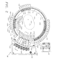
- Figure 1 is a perspective view of an analyzer in accordance with the present invention.
- Figure 2 is a top view of the turntable, capillary sample end platform and capillary detection end platform of the analyzer of Figure 1.
- Figure 3 is a partial section view taken along line 3-3 of Figure 2.
- Figure 4 is an enlarged side section view of the sample end of the capillaries.
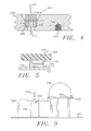
- Figure 5 is a side section view of a reagent delivery tube positioned to delivery reagent to a reagent segment.
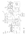
- Figure 6 is a simplified functional diagram of the fluid system of the analyzer of Figure 1.
- Figure 7 is a cross-section view of a detection station for the detection end of capillaries.
- Figure 8 is a block diagram of the control system and electronics of the analyzer of Figure 1.
- Figure 9 is a simplified side view of another embodiment of a turntable and capillary system for use in an analyzer in accordance with the present invention.
- With respect to Figures 1 and 2, an
analyzer 40 in accordance with the present invention is formed on a chassis having a lower horizontal mountingplate 42 and an upper horizontal mountingtray 44. The mountingplate 42 supports aturntable assembly 46, acapillary assembly 48, afluid control assembly 49, aprobe assembly 50, and a pipettor-dilutor assembly 52. The upper mountingtray 42 supports acard cage 54, low voltageDC power supply 56, and lightsource power supply 58. A plurality ofreagent reservoirs 62 are also supported at the front edge of the upper tray for easy access by an operator. Preferably, thereservoirs 62 include awater bottle 64, abuffer bottle 66 containing a suitable running buffer such as boric acid at pH 10.2 , awash solution bottle 68 containing sodium hydroxide (NaOH), and adiluent bottle 70 containing a suitable diluent such as phosphate buffered saline. The diluent may additionally include if desired specific chemical reference markers, such as is disclosed in U.S. Patent Application Serial Number 708,424, filed May 31, 1991 in the name of Fu-Tai A. Chen, and entitled Identification of Sample Constituents Utilizing Capillary Electrophoresis. The placement of thereservoirs 62 on theupper tray 44 allows gravity feed of the reagents contained in thereservoirs 62 throughout theanalyzer 40. Theanalyzer 40 may also include suitable top, side and front panels and doors (not shown in Figure 1) to enclose theanalyzer 40, all in a conventional fashion. - The
turntable assembly 46 provides support and automated positioning for sample tubes and reagent segments. More particularly, theturntable assembly 46 includes aturntable 100 rotatably supported by ashaft 104 at the center of theturntable 100. Theshaft 104 is part of a motor and drive belt assembly 106 (shown in simplified phantom outline in Figure 1) that is supported by the mountingplate 42 and is beneath and inside theturntable 100. The motor anddrive belt assembly 106 is operated so as to rotate theturntable 100 andshaft 104 in a controllable fashion. - The
turntable 100 includes anupper surface 110 and a lowerannular support 112. Theupper surface 110 includes a plurality ofarcuate ribs 114 disposed near the outer periphery of theupper surface 110 and, in the embodiment disclosed herein, theribs 114 define ten equally spaced positions about the periphery of theupper surface 110. Between theribs 114 arepins 115. The lowerannular support 112 includesposts 116 extending upwardly from thesurface 112. Pairs ofposts 116 are disposed radially outwardly with respect to each of theribs 114. Thus, twentyposts 116 are disposed on theannular support 112 with respect to the tencorresponding ribs 114. - The
turntable 100 also includes an inner depending lip 118 (Figure 3) that includes ten equally spaced notches (not shown) formed into the lower edge of thelip 118. The notches are sized to be detected by an optical detector (not shown) to thus determine the rotational position of the table 100, all in a conventional fashion. -
Sample tube sectors 130 may be suspended from theannular support 112 andposts 116 to support a plurality of sample tubes, such as blood draw orsample tubes 132, about the periphery of theturntable 100. Thesample tube sectors 130 include ahorizontal flange 134 that is adapted to rest upon theannular support 112 and twoholes 136 that receive theposts 116 to thereby removably secure thesample sector 130 to theturntable 100, thehorizontal flange 134 resting upon theannular support 112. - A plurality of
reagent segments 140 may be removably positioned about the periphery of theupper surface 110. Eachreagent segment 140 is curved to match the curve at the periphery of theupper surface 110. The reagent segments fit over theribs 114, theribs 114 thus fitting inside thereagent segments 140 near the outer edges thereof, thereby removeably retaining thereagent segments 140 on theupper surface 110. Thereagent segment 140 includes sixreservoir groups 142 and eachreservoir group 142 in turn includes fourindividual reservoirs 144. Eachreservoir 144 is adapted to hold approximately 200 f..ll of liquid when filled to the maximum usable capacity. Fivereagent segments 140 are seen in Figure 2. - The
capillary assembly 48 provides support for a plurality of capillaries as well as the associated electrodes for establishing current flow through the capillaries and optical fiber holders for positioning optical fibers used for detection. As used herein, the "sample end" of a capillary is the end into which a sample is introduced into the capillary before electrophoretic separation along the length of the capillary, and the "detection end" of a capillary is the end proximate the detection or detector means used to detect the results of electrophoretic separation occurring along the length of the capillary. - In the embodiment disclosed herein, the
capillary assembly 48 supports sixcapillaries 200, also sometimes identified individually in this specification and in the Figures ascapillaries 200a-200f as appropriate. Thecapillaries 200 are conventional silica quartz glass capillaries formed with a thin conformal coating of a polyimide, having an inside diameter within a range of about five microns to two hundred microns and more particularly in a range of approximately twenty five microns to seventy five microns, and an outer diameter of about one hundred forty microns to three hundred seventy five microns, respectively. - The sample ends of the
capillaries 200 are removably supported by asample end plate 202. Thesample end plate 202 is generally arcuate and includes six capillary end retainers 204 (Figure 4). The vertical center lines of thecapillary end retainers 204 are spaced to align with the spacing between corresponding ones of thereservoirs 144 within thereservoir groups 142 of areagent segment 140 positioned on theturntable 100. This spacing aligns the ends of thecapillaries 200 over, for example, a first one of thereservoirs 144 within eachreservoir group 142 when so positioned by the rotation of the turntable, and so on. - Each of the
retainers 204 includes a shoulderedhole 206 through thesample end plate 202 defining anannular shoulder 208. A polarized barium ferrite annular magnetic 210 is fixed within thehole 206 against theshoulder 208. - To be retained by the
sample end plate 202,sample end 212 of each of thecapillaries 200 includes a second polarized barium ferriteannular magnets 214 bonded to the capillary 200 proximate thesample end 202 by means of a suitable rubber adhesive 216. With the capillary 200 positioned as illustrated in Figure 4, the abutting ends of themagnets magnets sample end plate 202 and positions thesample end 212 for access toreservoirs 144 within areagent segment 140 that may be carried by theturntable 100. - Two
access holes sample end plate 202, theaccess hole 222 having a larger diameter than theaccess hole 220. Theaccess hole 220 is formed to align overreservoirs 144 inreagent segments 140 that may be positioned on theturntable 100 beneath thesample end plate 202. Theaccess hole 222 is aligned to provide access through thesample end plate 202 to sampletubes 132 that are held by thesample tube sectors 130 beneath thesample end plate 202. - Two lengths of small bore
rigid tubing sample end plate 202 proximate thesmaller access hole 220.Tubing lengths group 230 of reagent dispensing tubes, are of sufficient length to pass through the sample end plate 202 (Figure 5) and are fixed at a slight angle with respect to vertical. Thegroup 230 of tubes is positioned to deliver liquid reagents toreservoirs 144 ofreagent segments 140 that may be positioned beneath the open ends of thetubing lengths sample end plate 202. - The
sample end plate 202 includes a plurality of bare wire electrodes 240 (Figures 3 and 4) depending from the lower surface of thesample end plate 202 and radially aligned with respect to the center of theturntable 100 with corresponding ones of thecapillary end retainers 204. Thus in the embodiment disclosed herein, there are sixsuch electrodes 240 corresponding to the sixcapillary end retainers 204. Theelectrodes 240 are fixed by means of a rubber adhesive within agroove 242 formed on the lower side of thesample end plate 202 and are connected to awire 244 disposed within thegroove 242. Thewire 244 is routed through alarger intersecting groove 246 and is likewise retained within thelarger groove 246 by a suitable rubber adhesive. Thewire 244 and thus theelectrodes 240 are connected to one output terminal of a high voltage d.c.power supply 248 via a suitable insulated wire (not shown). - The
sample end plate 202 is adapted for vertical displacement with respect to thehorizontal turntable 100. Posts 250 (one of which is shown in Figure 1) are fixed to the mountingplate 42 and in turn supportlinear bearings 252 that are fixed to the outer corners of theplate 202. Anelevator stepper motor 254 vertically actuates ashaft 256 that is in turn fixed to theplate 202. Actuation of thestepper motor 254 accordingly raises and lowers theplate 202 between mechanical stops defining theplate 202 up and down positions. - The
capillary assembly 48 also includes amanifold plate 300. Themanifold plate 300 is mounted atop theposts 250 and asupport post 344 and includes anarcuate edge 302 proximate the outer edge of thesample end plate 202. Themanifold plate 300 supports sixdetection stations 320 that are aligned above a conduit ormanifold 322 formed in the interior of themanifold plate 300. In the embodiment disclosed herein, the manifold 322 is in the form of anarcuate groove 323 formed into themanifold plate 300 above a largerarcuate groove 324. Abare wire electrode 325 is disposed within thearcuate groove 323 throughout the length of thearcuate groove 323. Theelectrode 325 exits through and is sealed within a hole (not shown) formed through themanifold plate 300 and is connected to system ground. Anarcuate closing piece 326 is sealed within the largerarcuate groove 324 to close themanifold 322. - To provide access to the manifold 322 by the
capillaries 200, six holes 328 (Figures 3 and 7) are formed through the upper surface of themanifold plate 300, theholes 328 each including ashoulder 330 reducing to asmaller diameter portion 332 of thehole 328. Anannular seal 334 is fixed within thehole 328 and includes aninternal taper 336 for directing the end of the capillary 200 into the manifold 322 as is described hereinbelow. - Two
tubing couplings 338 and 340 (Figure 6) are fixed within holes formed through theclosing piece 326 and are in communication with the manifold 322, thetubing couplings manifold 322. - The
manifold plate 300 also includes a wash station 346 (Figures 2 and 6). Thewash station 346 includes an inner open-top fountain 348. Water solution may be feed through a port in the bottom of thefountain 348, overflowing the top of thefountain 348 into acatch basin 349. Thecatch basin 349 in turn includes a drain port through which wash effluent may be removed from thewash station 346. - The six
detection stations 320 are coaxially aligned above the corresponding sixholes 328 and seals 334. Each of thedetection stations 320 includesvertical support structures 350 and 352 (Figure 7) having transverse extendingarms threads arms vertical support structures capillaries 200 and input and output optical fiber assemblies. - The detection end of each the
capillaries 200 is retained within a holder400 that is formed around thecapillary 200. Theholder 400 includes ahandle portion 402, a flattenedportion 404 and a cylindricaldownstream portion 406 that forms a fluid seal around thecapillary 200. The downstream portion is adapted to be received by theseal 334 to establish a sealing relationship between thedownstream portion 406 and theseal 334. - In the
analyzer 40 of the present invention, light for the detection of the sample constituents within thecapillaries 200 is brought to thecapillaries 200 by fiber optics and is lead from thecapillaries 200 to suitable detectors by means of fiber optics. More particularly, a single deuterium lamp within a heat sink housing 420 (mounted beneath the mountingtray 44 as shown in phantom in Figure 1) is directed to a single optical fiber light guide 422 (Figure 3) which is in turn split at anoptical fiber splitter 424 into six input optical fiber light guides 426. - Continuing the description with respect to one of the light guides 426 as seen in Figures 3 and 7 and it being understood that the remaining light guides 426 have corresponding structure, the input optical
fiber light guide 426 terminates in aholder mechanism 428 and includes anut configuration 430 that is removably fastened onto thearm 354. Theholder mechanism 428 is positioned with respect to awindow 432 formed into the flattenedportion 404 of theholder 400, exposing thecapillary 200. Preferably, the coating on the capillary 200 is removed to allow the passage of UV light from the end of the input opticalfiber light guide 426 through the capillary to an output opticalfiber light guide 434. The window and a technique for making the window are described in U.S. Patent Application Serial Number , attorney docket number 8751, entitled Capillary Electrophoresis Detection, in the names of Waska, Klein and Johnson, filed concurrently herewith, and which is incorporated herein by reference. Although the window and technique for making the window are prefer- rably as that described in such application, other techniques for removing the capillary coating can be used. - The
output light guide 434 includes at its end aholder mechanism 436 which may be removable fixed within thearm 356 by means of anut configuration 438. The opposite end of the output opticalfiber light guide 434 is applied to adetector housing 450 that includes a suitable detector, such as a silicon photo-detector 640 (Figure 8) to detect the light that passes through the capillary 200. - The fluid control system of the
analyzer 40 includes thereservoirs 62, capillary assembly 48 (including thesample end plate 202 and the manifold plate 300),fluid control assembly 49,probe assembly 50, pipettor-dilutor assembly 52, and thewaste bottle 74, as well as tubing interconnecting these elements. Such tubing described herein is not shown in Figures 1, 2 and 3 for the sake of simplicity but is instead shown in schematic form in Figure 6. With reference to Figure 6, thewater bottle 64,buffer bottle 66,wash solution bottle 68,diluent bottle 70,waste bottle 74,wash station 346 andmanifold 322 are connected to thefluid control assembly 49. Thefluid control assembly 49 includes abuffer valve 501 and an auxili-aryventvalue 502 connected between thebuffer bottle 66 and one end of the manifold 322 via amanifold line 503 and thetubing coupling 338. Avent tube 504 is connected between thevalves water valve 505 is connected between thewater bottle 64 and thetubing coupling 338 via themanifold line 503. - The
coupling 340 in the second end of the manifold 322 is connected to a vent tube having an open end. Amanifold vent valve 507 provides a valving function in thevent tube 506 near the open end of thevent tube 506. The open ends of thevent tubes buffer bottle 66 or thewater bottle 64 to avoid reagent spillage through either of the vent tubes 504,506 if a valve failure should occur. Thecoupling 340 is also connected to amanifold drain valve 508 which in turn is connected to thewaste bottle 74 via amainfold drain line 509. - The vacuum for the fluid system is developed by a
vacuum pump 510, part of thefluid control assembly 49. The vacuum output from thevacuum pump 510 is connected to one side of avalve 512, the other side of which is connected to avacuum regulator 514. The regulated output of thevacuum regulator 514 is connected to thewaste bottle 74 via avacuum source line 515. Aregulator bypass valve 516 is connected between the vacuum output from thevacuum pump 510 and thevacuum source line 515. Theregulator 514 is provided to achieve a controlled vacuum that is used, for example, for drawing sample into the sample ends of thecapillaries 200. Theregulator 514 is bypassed by thevalve 516 when less precise fluid control is needed, such as in simply drawing wash or buffer reagent through thecapillaries 200 as is described below with respect to the operation of theanalyzer 40. - A
probe wash valve 517 is connected between thewater bottle 64 and theinner fountain 348 of thewash station 346 and awash vacuum valve 518 is connected between the drain port of thecatch basin 349 and themanifold drain line 509. Thevalves valve 507 are normally closed, that is, the valve is closed when the solenoid is deenergized or inactivated, and open when the solenoid is energized or activated.Valve 507 is normally opened. - Thus it is seen that the
manifold line 503 is in common with thevalves coupling 338. On the other hand, themanifold drain line 509 is in common with themanifold drain valve 508, washvacuum valve 518, and thewaste bottle 74. - A solenoid controlled
wash solution valve 520 is connected between the NaOHwash solution bottle 68 and thetube 224 included in the group ofreagent dispensing tubes 230. Similarly, a solenoid controlled normally closedbuffer valve 522 is connected between thebuffer bottle 66 and thetube 226 included in the group ofreagent dispensing tubes 230. All of the valves described to this point, but for themanifold vent valve 507, may be included in thefluid control assembly 49, and thevalve 507 may be mounted on theupper tray 44 adjacent the open end of thevent tube 506. - The
probe assembly 50 may be of a conventional design and includes aprobe arm 530 which at one end is supported by adisplacement mechanism 532 and at the other end supports a fluid conducting probe 534 and a needle 536. The needle 536 is used by the analyzer control circuitry (elevator controller 668 described with reference to Figure 8) to detect the level of fluid as, for example, by sensing conductivity of the fluid into which the probe 534 and needle 536 come into contact. - The
displacement mechanism 531 includes avertical displacement motor 532 and ahorizontal displacement motor 533 which together are controlled to lift and rotate theprobe arm 530 and the probes 534 and 536 all in a conventional fashion. - The pipettor-
dilutor assembly 52 is connected viafluid carrying tubing 560 to the fluid conducting probe 534. Theconduit 560 is connected to arotary valve 562 that connects a motor drivenpipette 564 to either thediluent bottle 70 as shown in Figure 6 or to the fluid conducting probe 534 as shown in the alternate valve position in phantom in Figure 6. Thevalve 562 is controlled by amotor 566 and the pipette is controlled by means of amotor 568 connected through ascrewdrive mechanism 570 tothe pipette 564. The pipettor-dilutor 52 is of a conventional design and may be, for example, model XL3000 available from Cavro (Sunnyvale, California, U.S.A.). - The
analyzer 40 further includes a computer-basedcontrol system 590 to control the automated features of theanalyzer 40 and to provide a suitable user interface. In the embodiment disclosed herein, and as illustrated in block form in Figure 8, the computercon-trol system 590 includes acentral computer 592 which includes amicroprocessor board 600. The microprocessor may be, for example, a type i386 available from Intel Corporation. Themicroprocessor board 600 is interfaced with amemory board 602 and in turn floppy and hard disk drives 604. Themicroprocessor board 600 is also interfaced with akeyboard 606,video board 608, serial andparallel ports 610, analog-to-digital converter 612, and aninterface 614. Thevideo board 608 in turn drives a conventional computer computer color monitor 616 having adisplay screen 618. It is to be understood that thecomputer 592 may take the form of a conventional IBM compatible personal computer (IBM is a trademark of International Business Machines Corporation) of the type very well known in the art. Further, theconverter 612 andinterface 614 can interface with such a computer via one or more cards that plug into the computer bus, all in a conventional fashion. - With respect to the analog portion of the control system and as described previously, output optical fiber light guides 434 are directed towards six
solid state detectors 640. The output of thedetectors 640 are in turn applied to sixrespective amplifiers 642 whose outputs are applied to ananalog signal interface 644. Thesignal interface 644 selects the signal and scales the selected signal for analog-to-digital conversion. The selected analog output is applied to the analog-to-digital converter 612. Areference voltage amplifier 646 is also applied to thesignal interface 644 for calibration of theanalog signal interface 644 and the analog-to-digital converter 612. - A
current monitoring resistor 650 is placed in series in the high voltage circuit formed by thehigh voltage powersupply 248 and thecapillaries 200. Anamplifier 648 senses the voltage across theresistor 650 and the output of theamplifier 648 is applied to theanalog signal interface 644 to thus provide a means to monitor the current through thecapillaries 200. - Under the control of the
microprocessor board 600, theinterface 614 provides several serial data interfaces as well as switched outputs and digital-to- analog outputs for the sensing and control of assemblies and devices in theanalyzer 40. Serial interfaces are provided to aturntable motor controller 660, a probe horizontaldisplacement motor controller 662, a probe verticaldisplacement motor controller 664, a pipettor-dilutor motor controller 660, and an elevatorstepper motor controller 668. Themotor controllers - The
interface 614 also includes a digital-to-analog converter that provides a voltage control signal to the highvoltage power supply 248 to thereby adjust the voltage produced by thepower supply 248. Theinterface 614 also includes switched outputs which switch on and off the highvoltage power supply 248, thevacuum pump 510 and the solenoid operatedvalves interface 614 is responsive to asafety interlock switch 670 which is actuated when the ana- iyzer40 panels (not shown) are removed, thereby disabling the highvoltage power supply 248 by means of themicroprocessor board 600. - For the purpose of the following description of an analysis cycle of the
analyzer 40, it is assumed that the analyzer40 is in a ready state with the fluid probe 534 primed with diluent and raised to a park position above, for example, thewash station 346. Priming may be accomplished, for example, by drawing diluent into the pipettor-dilutor 52 from thediluent bottle 70, changing the position of thevalve 562 to that shown by the dashed line in Figure 6, and expelling diluent into theline 560 until the fluid probe 534 is primed. Thesample end plate 202 is also raised such that the sample ends of thecapillaries 200 and theelectrodes 240 clear the tops ofreagent segments 140 that may be carried by theturntable 100, theturntable 100 is in a home position,vacuum pump 510 and highvoltage power supply 248 are off, and all valves are in the normal or deenergized state. - Before the analysis cycle begins, it is also assumed that a
sample tube sector 130 is placed onto theturntable 100 at, for example, aload position 680. Thesector 130 holds sixsample tubes 132a through 132f, each containing a suitable sample for analysis, such as human blood serum. Also, an empty,clean reagent segment 140 is placed onto the turntable at theload position 680 inboard from the positionedsector 130 over the corresponding one of theribs 114. For the purpose of this description, the sixreservoir groups 142 in thereagent segment 140 at theload position 680 are identified asgroups 142a through 142f corresponding to the sixsample tubes 132a-132f, and the fourreservoirs 144 in each of thegroups 142a-142f are identified asreservoirs 144a through 144d. - The
keyboard 606 is operated to define a capillary electrophoresis analysis cycle. Instructions given by way of thekeyboard 606 to thecontrol system 590 may include, for example, the location of thesample sector 130 on theturntable 100, the number ofsample tubes 132 on the sample sectors 130 (in this example, sixsample tubes 132a-132f), and the analysis parameters for each batch analysis performed with respect to thesample tubes 132 carried on asample sector 130. The analysis parameters may include whether samples are to be drawn into thecapillaries 200 by vacuum or by application of high voltage, the length of time for such sample injection into the capillary 200 ends, the voltage to be applied during electrophoresis, and the length of time that electrophoresis is to be performed. - The
analyzer 40 is commanded to begin the specified analysis by way of the keyboard and the control system takes over automated control of theanalyzer 40.Turntable 100 is rotated to position thefirst sample tube 132a under thehole 222 and beneath the arc described by the fluid probe 534. The probe 534, in an initial raised park position, is rotated to a position above thefirst sample tube 132a. Theprobe assembly 50 and the pipettor-dilutor assembly 52 are controlled to lower the tip of the fluid probe 534 into the sample contained within thesample tube 132a, draw a predetermined volume of sample into the fluid probe 534, raise the probe 534 and rotate it above thefirst reservoir 144a of thereservoir group 142a inboard from thesample tube 132a, and lower the tip of the probe 534 into thereservoir 144a. The pipettor-dilutor assembly 52 is controlled to dispense the sample into thereservoir 144a and also dispense an additional volume of diluent into thereservoir 144a. - The probe 534 is raised, rotated and lowered into the
inner fountain 348 of thewash station 346. Typically, to wash the probe, thewash valve 517, washvacuum valve 518, andbypass valve 516 are opened, and thevacuum pump 510 is operated to flow water into thefountain 348 around the probe and remove waste liquid via the drain port in thecatch basin 349. Additional diluent may be flowed from the probe 534 into thefountain 348 by operation of the pipettor-dilutor assembly 52 to assure internal cleaning of the fluid probe 534. - As an alternative, the above sample dilution cycle can be repeated but with the
probe assembly 50 and the pipetor-dilutor assembly 52 controlled to draw the first dilution of the sample from thereservoir 144a into the fluid probe 534, transfer such first dilution to thefourth reservoir 144d and add a predetermined amount of diluent to thefourth reservoir 144d through the fluid probe 534. In this way, a second dilution of the sample is created for use in the electrophoretic analysis or in a second electrophoretic analysis of the sample. - The
turntable 100 is rotated to position reservoirs 144b and 144c within thereservoir group 142a beneath the wash andbuffer reagent tubes Valves - The above sample, running buffer and wash solution dispensing procedures are repeated for the remaining samples in the sample tubes 132b-132f to dispense diluted sample, running buffer and wash solution into
respective reservoirs 144a, 144b, and 144c, respectively, in the reservoir groups 142b through 142f. - Assuming that the
capillaries 200 are not filled with running buffer, theturntable 100 is rotated so as to position the sample ends of thecapillaries 200 above the reservoirs 144b in thereservoir groups 142a through 142f that contain running buffer. The elevator stepper motor 154 is controlled to lower thesample end plate 202 until it rests atop thepins 115 and the sample ends of thecapillaries 200a through 200f as well as the correspondingelectrodes 240 are lowered into the running buffer reservoirs 144b of thereservoir groups 142a through 142f, respectively. Thevacuum pump 510 is operated and theregulator bypass valve 516 is opened to produce a vacuum through thewaste bottle 74 and themanifold drain line 509.Manifold vent valve 507 is closed andmanifold drain valve 508 is opened, applying vacuum to the manifold 322, thereby drawing running buffer through thecapillaries 200. After a suitable predetermined time period, thevacuum pump 510 andvalve 516 are deactivated. Thebuffer valve 501,auxiliary vent valve 502, andmanifold vent valve 507 are opened and thedrain valve 508 is closed to complete the filling of the manifold 322 with running buffer by gravity feed from the runningbuffer bottle 66. It is much more time efficient to fill the manifold 322 with running buffer by means of gravity feed rather than attempting to fill the manifold 322 with running buffer delivered through thecapillaries 200 because of the extremely small inside diameter of thecapillaries 200 and the corresponding very low liquid flow rates through those capillaries, even with a vacuum applied via thewaste bottle 74 by means of thevacuum pump 510 andvalve 516. - With the manifold 322 filled,
buffer valve 501 andauxiliary vent valve 502 are closed. Because the manifold 322 is filled with buffer by gravity feed, a fluid column is supported within thevent tube 506 essentially to the level of the buffer withinbuffer bottle 66. This fluid column creates a hydrostatic back pressure in the manifold 322 that can slow the separating flow of samples through the capillaries and cause run-to-run variations is separation time. To prevent this, thevacuum pump 510 is operated, andbypass valve 516,manifold drain valve 508 andmanifold vent valve 507 are opened to draw or sip this fluid column into thewaste bottle 74 and eliminate the potential for back pressure, normalizing the fluid pressure in the manifold essentially to atmospheric or ambient pressure and thus the same pressure on thereservoirs 144. - Alternatively, the
capillaries 200 may be filled prior to the commencement of the analysis cycle. This can be accomplished by positioning areagent segment 140 onto theturntable 100, filling the reservoirs 144b in thereservoir groups 142a through 142f of thesegment 140 with running buffer, and operating theelevator stepper motor 254,vacuum pump 510 andvacuum valve 516, and the buffer, vent and drainvalves - In order to load sample into the
capillaries 200, theelevator stepper motor 254 is controlled to raise thesample end plate 202 such that the ends of thecapillaries 200 and theelectrodes 240 clear thereagent segments 140. Theturntable 100 is rotated to position the sample ends of thecapillaries 200 above thesample reservoirs 144a within therespective reservoir groups 142a through 142f and theelevator stepper motor 254 is controlled to lower thesample end plate 202 onto thepins 115 such thatthe sample ends of thecapillaries 200 are within the diluted sample contained within thesample reservoirs 144a. Thevacuum pump 510 andvalves manifold 322. By appropriate timing of the application of the regulated vacuum to the manifold 322, a predetermined volume of diluted samples from the sixreservoirs 144a in thereservoir groups 142a - 142f are drawn to the six respective sample ends of thecapillaries 200a - 200f. - The
vacuum pump 510 andvalves sample end plate 202 is raised,turntable 100 is rotated andsample end plate 202 is again lowered to position the sample ends of thecapillaries 200a - 200f and the correspondingelectrodes 240 into the running buffer reservoirs 144b within therespective reservoir groups 142a through 142f. - The high
voltage power supply 248 is commanded to apply a high voltage across thecapillaries 200. More particularly, the high voltage power supply is connected to thewire 244 which is turn connected to the sixelectrodes 240 that are now disposed within the buffer reservoirs 144b. The other polarity developed by the highvoltage power supply 248 is connected via system ground to themanifold electrode 325 disposed within themanifold 322. By the application of this voltage, preferably in the range of approximately 6000 to 10,000 volts DC, capillary electrophoresis begins with the samples previously drawn into the sample end ofcapillaries 200. - With the electrophoresising voltage applied across the
capillaries 200, electrophoretic separation occurs and during the electrophoresising period of, for example, two minutes to four minutes, separated samples (depending upon the mobility of the molecules in the samples) flow past thewindows 432 within each of thecapillaries 200. The light directed through thewindows 432 between the input and output optical fiber optic light guides 426 and 434 and thus through the bores of the capillaries is periodically sampled and processed by thedetectors 640,preamplifiers 642,analog signal interface 644, analog-to-digital converter 612 and themicroprocessor board 600 to create digital values related to the absorbance of the sample constituents. - Preferably, the values are arranged and stored for each of the
capillaries 200a - 200f creating six channels or arrays of data corresponding to the sixcapillaries 200a - 200f. The values may are stored as files on one of the disk drives 604 for further manipulation and data analysis and reduction by thecontrol system 590 or external "host" computing means. - After the sample analysis is completed and the required data is collected by the system controller, the
microprocessor board 600 controls the highvoltage power supply 248 to remove the electrophoresising voltage from thecapillaries 200. Theelevator stepper motor 254 is actuated to raise thesample end plate 202 such that the sample ends of thecapillaries 200 and theelectrodes 240 clear thereagent segment 140 and theturntable 100 is rotated to position the wash fluid in the reservoirs 144c beneath the sample ends of thecapillaries 200. Theelevator stepper motor 254 again is controlled to lower thesample end plate 202 to position the sample ends of thecapillaries 200a - 200f within wash solution contained in the reservoirs 144c within thereservoir groups 142a through 142f, respectively. Regulated vacuum is again applied to the manifold 322, drawing the wash solution through thecapillaries 200 to themanifold 322. After a predetermined time period, thecapillaries 200 are recharged with running buffer, preparing the capillaries for the next analysis. Water in thebottle 64 may be used, for example, for maintenance washing of the manifold 322 when theanalyzer 40 is shut down by opening thevalve 505. Thecapillaries 200 may be stored for a long idle period in a dry state after suitable cleaning. Thevent tube 504 may be used when draining the manifold 322 via thevalves waste bottle 74 with vacuum applied. - Additional
sample tube sectors 130 may be placed onto theanalyzer 40 and the batch parallel analysis cycle just described may be repeated. - Thus, the analyzer40 of the present invention enables the batch parallel analysis of samples through a plurality of capillaries, the capillaries sharing a common manifold at the detection end of the capillaries.
- By using the common manifold, capillary electrophoresis can be performed in a reliable, efficient manner using a analyzer that does not include complicated individual fluid channels for each of the capillaries. Capillary preparation, sample loading, electrophoresising, capillary cleaning and reloading are more efficiently accomplished by means of the common manifold, and can be more simply accomplished as, for example, by the use of gravity feed or simultaneous, parallel vacuum feed. Such simplicity eliminates additional pumps, pinch valves, rotary valves and the like.
- It is to be recognized that the
reagent segments 140 may be brought to the sample ends of thecapillaries 200 other than by means of theelevator stepper motor 254 raising and lowering thesample end plate 202. For example, and with reference to Figure 9, an alternative version of an analyzer in accordance with the present invention may include aturntable 700 mounted to a turntable rotational andvertical displacement mechanism 702 which is in turn supported by means of ananalyzer base place 706. The mechanism includes means for raising and lowering theturntable 700, such as a vertical displacement motor and mechanism, and a rotational displacement motor and mechanism, all of conventional design. Acapillary assembly 704 is fixed with respect to thebase plate 706 and includes a plurality ofcapillaries 708 andmanifold 709 essentially identical to thecapillaries 200 andmanifold 322. Under the control of a suitable control system similar to that described above, themechanism 702 rotates the turntable about ashaft 710 and also vertically displaces theturntable 702 upwardly and downwardly as illustrated by thearrows 712. Accordingly, the sample ends of thecapillaries 708 as well as electrodes (not shown) to provide the electrical connection may be placed into and removed from reservoirs contained in reagent segments similar to thosereagent segments 140 described above. With respect to either the embodiment of theanalyzer 40 or the embodiment disclosed in Figure 9, the sample ends of a plurality of capillaries are simultaneously placed within reservoirs and reagent segments, enabling batch parallel analysis and processing of samples by the capillaries. - Other modifications to the
analyzer 40 are possible. For example, thecapillary assembly 48 may be disposed within a temperature controlled chamber that is heated and cooled, for example, by Peltier devices to provide a thermally stable environment in which thecapillaries 200 are operated. Such a temperature stabilized environment may be particularly advantageous where the batch parallel analysis performed by the capillaries must be temperature stabilized, capillary to capillary, to thereby eliminate the effects of temperature on the results detected by theanalyzer 40. - It is also to be understood that the number of
capillaries 200 carried in thecapillary assembly 48 may be increased or decreased according, for example, to the number of samples that may be carried by sample sectors. - The
control system 590 can display the electro- phoretograms for the six channels on, for example, themonitor 616, in a conventional form such as an electrophoretogram with time on a horizontal axis and absorbance on the vertical axis. - The present invention is not to be limited to the embodiment disclosed herein, but is to be afforded the full scope of the appended claims and all equivalents thereof.
Claims (45)
Applications Claiming Priority (2)
| Application Number | Priority Date | Filing Date | Title |
|---|---|---|---|
| US07/916,308 US5413686A (en) | 1992-07-17 | 1992-07-17 | Multi-channel automated capillary electrophoresis analyzer |
| US916308 | 1992-07-17 |
Publications (3)
| Publication Number | Publication Date |
|---|---|
| EP0581413A2 true EP0581413A2 (en) | 1994-02-02 |
| EP0581413A3 EP0581413A3 (en) | 1994-09-07 |
| EP0581413B1 EP0581413B1 (en) | 2003-04-02 |
Family
ID=25437035
Family Applications (1)
| Application Number | Title | Priority Date | Filing Date |
|---|---|---|---|
| EP93303429A Expired - Lifetime EP0581413B1 (en) | 1992-07-17 | 1993-04-30 | Multi-channel capillary electrophoresis system |
Country Status (7)
| Country | Link |
|---|---|
| US (1) | US5413686A (en) |
| EP (1) | EP0581413B1 (en) |
| JP (1) | JP2526531Y2 (en) |
| AT (1) | ATE236391T1 (en) |
| AU (1) | AU652096B2 (en) |
| CA (1) | CA2094226C (en) |
| DE (1) | DE69332816T2 (en) |
Cited By (11)
| Publication number | Priority date | Publication date | Assignee | Title |
|---|---|---|---|---|
| EP0776700A1 (en) * | 1995-12-08 | 1997-06-04 | The Institute of Physical and Chemical Research ( RIKEN) | Method for purification and transfer to separation/detection systems of DNA sequencing samples and plates used therefor |
| WO1997030347A1 (en) * | 1996-02-20 | 1997-08-21 | Waters Investments Limited | Capillary chromatography detector apparatus |
| US5783397A (en) * | 1995-12-11 | 1998-07-21 | Northeastern University | Screening natural samples for new therapeutic compounds using capillary electrophoresis |
| US6013168A (en) * | 1997-03-03 | 2000-01-11 | Shimadzu Coporation | Microchip electrophoresis apparatus |
| WO2001038844A2 (en) * | 1999-11-12 | 2001-05-31 | Motorola, Inc. | Capillary electrophoresis devices incorporating optical waveguides |
| EP1212608A1 (en) * | 1999-08-31 | 2002-06-12 | Spectrumedix Corporation | Automated parallel capillary electrophoresis system with hydrodynamic sample injection |
| WO2003006163A1 (en) * | 2001-07-09 | 2003-01-23 | Greiner Bio-One Gmbh | Analysis device |
| US6652809B1 (en) | 1997-09-17 | 2003-11-25 | Glaxo Research And Development Limited | Apparatus for performing photometric assays |
| EP1406092A2 (en) * | 2002-10-02 | 2004-04-07 | Matsushita Electric Industrial Co., Ltd. | Sampling element, treatment device and treatment method for an analyte |
| EP2410323A1 (en) * | 2010-07-20 | 2012-01-25 | Arkray, Inc. | Sample analysis apparatus and sample analysis method |
| WO2020190969A1 (en) * | 2019-03-18 | 2020-09-24 | Life Technologies Corporation | Multi-capillary optical detection system |
Families Citing this family (55)
| Publication number | Priority date | Publication date | Assignee | Title |
|---|---|---|---|---|
| CA2094343A1 (en) * | 1992-07-17 | 1994-01-18 | Gerald L. Klein | Method and apparatus for displaying capillary electrophoresis data |
| US5605666A (en) * | 1993-04-16 | 1997-02-25 | Beckman Instruments, Inc. | Capillary retaining system |
| US5439578A (en) * | 1993-06-03 | 1995-08-08 | The Governors Of The University Of Alberta | Multiple capillary biochemical analyzer |
| US5463910A (en) * | 1994-05-16 | 1995-11-07 | Avl Scientific Corporation | Multi-function aspirating device |
| US5900132A (en) * | 1995-03-23 | 1999-05-04 | Beckman Coulter, Inc. | Capillary holder |
| DE29607239U1 (en) | 1996-04-23 | 1996-06-05 | J & M Analytische Mess & Regeltechnik Gmbh | Capillary holder |
| WO1997042494A1 (en) * | 1996-05-06 | 1997-11-13 | University Of Massachusetts | Rapid soil nutrient analysis |
| US6063251A (en) * | 1997-05-30 | 2000-05-16 | Spectrumedix Corporation | Electrically insulated capillary arrays for electrophoretic applications |
| US5885430A (en) * | 1996-10-04 | 1999-03-23 | Spectrumedix Corporation | Capillary tube holder for an electrophoretic apparatus |
| JPH10239278A (en) * | 1997-02-24 | 1998-09-11 | Hitachi Ltd | Cataphoresis device |
| US5904824A (en) * | 1997-03-07 | 1999-05-18 | Beckman Instruments, Inc. | Microfluidic electrophoresis device |
| US6027627A (en) * | 1997-06-30 | 2000-02-22 | Spectrumedix Corporation | Automated parallel capillary electrophoretic system |
| US6365024B1 (en) | 1997-06-30 | 2002-04-02 | Spectrumedix Corporation | Motorized positioning apparatus having coaxial carrousels |
| WO1999000664A1 (en) * | 1997-06-30 | 1999-01-07 | Spectrumedix Corporation | Automated parallel capillary electrophoretic system |
| JP3481828B2 (en) * | 1997-08-26 | 2003-12-22 | 株式会社日立製作所 | Electrophoresis analyzer, electrophoresis analysis method, and sample container used therefor |
| US6054032A (en) * | 1998-01-27 | 2000-04-25 | 3M Innovative Properties Company | Capillary electrophoresis array |
| GB9802600D0 (en) * | 1998-02-07 | 1998-04-01 | Eastman Kodak Co | Liquid separation |
| US6475361B1 (en) | 1998-02-20 | 2002-11-05 | Tetragen Sa | Capillary electrophoresis apparatus having filling/refilling system and methods for use thereof |
| US6103083A (en) * | 1998-02-20 | 2000-08-15 | Tetragen | Capillary electrophoresis apparatus and method |
| US6132582A (en) * | 1998-09-14 | 2000-10-17 | The Perkin-Elmer Corporation | Sample handling system for a multi-channel capillary electrophoresis device |
| US6103199A (en) * | 1998-09-15 | 2000-08-15 | Aclara Biosciences, Inc. | Capillary electroflow apparatus and method |
| US6217731B1 (en) * | 1998-10-21 | 2001-04-17 | Spectrumedix Corporation | Method and apparatus for monitoring and displaying the status of a parallel capillary electrophoresis device |
| USD430304S (en) * | 1998-12-24 | 2000-08-29 | Hitachi, Ltd. | DNA detector |
| US7329388B2 (en) * | 1999-11-08 | 2008-02-12 | Princeton Biochemicals, Inc. | Electrophoresis apparatus having staggered passage configuration |
| US6406604B1 (en) * | 1999-11-08 | 2002-06-18 | Norberto A. Guzman | Multi-dimensional electrophoresis apparatus |
| EP1269171B1 (en) * | 2000-03-07 | 2006-05-31 | Northeastern University | Parallel array of independent thermostats for column separations |
| FR2808089B1 (en) | 2000-04-25 | 2002-07-05 | Sebia Sa | IMPROVED DEVICE FOR ANALYZING SAMPLES BY MULTICAPILLARY ELECTROPHORESIS WITH SOLID / SOLID THERMAL REGULATION |
| US6531041B1 (en) | 2000-07-20 | 2003-03-11 | Symyx Technologies, Inc. | Multiplexed capillary electrophoresis system with rotatable photodetector |
| US6544396B1 (en) | 2000-07-20 | 2003-04-08 | Symyx Technologies, Inc. | Multiplexed capillary electrophoresis system |
| US6462816B1 (en) | 2000-07-21 | 2002-10-08 | Symyx Technologies, Inc. | Parallel capillary electrophoresis system having signal averaging and noise cancellation |
| US6572750B1 (en) * | 2000-07-21 | 2003-06-03 | Symyx Technologies, Inc. | Hydrodynamic injector |
| US6783649B2 (en) * | 2000-12-01 | 2004-08-31 | Cetek Corporation | High throughput capillary electrophoresis system |
| US6764583B2 (en) * | 2000-12-13 | 2004-07-20 | The Regents Of The University Of California | Using impedance measurements for detecting pathogens trapped in an electric field |
| US20030132117A1 (en) * | 2002-01-14 | 2003-07-17 | Andras Guttman | Thin film electrophoresis apparatus and method |
| US7309409B2 (en) * | 2001-01-26 | 2007-12-18 | Biocal Technology, Inc. | Multi-channel bio-separation cartridge |
| WO2002059592A2 (en) | 2001-01-26 | 2002-08-01 | Biocal Technology, Inc. | Optical detection in a multi-channel bio-separation system |
| US20040266021A9 (en) * | 2001-01-26 | 2004-12-30 | Andras Guttman | Multicapillary fraction collection system and method |
| US6692708B2 (en) * | 2001-04-05 | 2004-02-17 | Symyx Technologies, Inc. | Parallel reactor for sampling and conducting in situ flow-through reactions and a method of using same |
| US6929779B2 (en) | 2001-06-22 | 2005-08-16 | Biocal Technology, Inc. | Optical detection in bio-separation device using axial radiation output |
| US6932940B2 (en) * | 2001-06-22 | 2005-08-23 | Biocal Technology, Inc. | Optical detection in bio-separation device using axial radiation input |
| US6870165B2 (en) | 2001-10-19 | 2005-03-22 | Biocal Technology, Inc. | Multi-color multiplexed analysis in a bio-separation system |
| JP3979830B2 (en) * | 2001-12-04 | 2007-09-19 | 株式会社日立ハイテクノロジーズ | Multi-capillary electrophoresis device |
| US7189361B2 (en) * | 2001-12-19 | 2007-03-13 | 3M Innovative Properties Company | Analytical device with lightguide Illumination of capillary and microgrooves arrays |
| US7208072B2 (en) * | 2002-01-18 | 2007-04-24 | Biocal Technology, Inc. | Multi-segment cartridge for bio-separation with multiplexed fluorescence detection |
| AU2003283663A1 (en) * | 2002-11-01 | 2004-05-25 | Cellectricon Ab | Computer programs,workstations, systems and methods for microfluidic substrates in cell |
| EP1579203A1 (en) * | 2002-12-20 | 2005-09-28 | Northeastern University | Precision controlled thermostat |
| WO2005036122A2 (en) * | 2003-10-14 | 2005-04-21 | Reverse Proteomics Res Inst Co | Method of interaction analysis and interaction analyzer |
| US8030092B2 (en) | 2003-11-07 | 2011-10-04 | Princeton Biochemicals, Inc. | Controlled electrophoresis method |
| CA2563310A1 (en) * | 2003-11-07 | 2005-05-26 | Princeton Biochemicals, Inc. | Multi-dimensional electrophoresis apparatus |
| US7932081B2 (en) | 2005-03-10 | 2011-04-26 | Gen-Probe Incorporated | Signal measuring system for conducting real-time amplification assays |
| US8658093B2 (en) * | 2007-07-06 | 2014-02-25 | Applied Biosystems, Llc | Devices and methods for the detection of analytes |
| KR100877810B1 (en) * | 2008-06-12 | 2009-01-12 | (주)백년기술 | Batch type chemical analyzer |
| EP2695846B1 (en) * | 2011-04-06 | 2016-05-04 | Mitsubishi Heavy Industries Food & Packaging Machinery Co., Ltd. | Rotary-type filling machine and method for calculating filling quantity for rotary-type filling machine |
| KR101244467B1 (en) * | 2011-05-26 | 2013-03-18 | 한국기계연구원 | Sample preparation device |
| US11198118B2 (en) | 2017-03-29 | 2021-12-14 | Princeton Biochemicals, Inc. | Integrated modular unit containing one or more analyte concentrator-microreactor devices to be coupled to a cartridge-cassette and methods of operation |
Citations (8)
| Publication number | Priority date | Publication date | Assignee | Title |
|---|---|---|---|---|
| US4284491A (en) * | 1978-11-13 | 1981-08-18 | C. Desaga Gmbh Nachf. Erich Fecht | Apparatus for electrophoresis |
| US4375401A (en) * | 1981-05-20 | 1983-03-01 | Nicholas Catsimpoolas | Electrophoresis system |
| EP0241940A2 (en) * | 1986-04-16 | 1987-10-21 | The Perkin-Elmer Corporation | Method of forming a capillary element for use in an electrophoresis instrument |
| EP0339779A2 (en) * | 1988-04-29 | 1989-11-02 | Beckman Instruments, Inc. | Automated capillary electrophoresis apparatus |
| US4908112A (en) * | 1988-06-16 | 1990-03-13 | E. I. Du Pont De Nemours & Co. | Silicon semiconductor wafer for analyzing micronic biological samples |
| EP0421595A2 (en) * | 1989-08-28 | 1991-04-10 | Northeastern University | Integrated temperature control/alignment system for a capillary electrophoretic apparatus |
| EP0443320A1 (en) * | 1990-01-24 | 1991-08-28 | ISCO, Inc. | Capillary electrophoresis technique |
| DE4230354A1 (en) * | 1991-09-13 | 1993-03-18 | Hitachi Ltd | Gel electrophoretic migration unit - has bundled capillaries spaced to facilitate sample injection and fluorescence detection |
Family Cites Families (23)
| Publication number | Priority date | Publication date | Assignee | Title |
|---|---|---|---|---|
| US3956099A (en) * | 1972-10-30 | 1976-05-11 | Louis Israel | Continuous preparative electrophoresis apparatus |
| US3932264A (en) * | 1973-11-12 | 1976-01-13 | Shimadzu Seisakusho Ltd. | Electrophoretic measurement system including means for determining zone boundries |
| US4124470A (en) * | 1974-04-30 | 1978-11-07 | Harald Dahms | Method and apparatus for electrophoresis |
| US4154669A (en) * | 1977-02-11 | 1979-05-15 | Pen Kem, Inc. | Automatic electrophoresis apparatus |
| JPS53129824A (en) * | 1977-04-19 | 1978-11-13 | Hitachi Maxell | Zinc alkali battery |
| JPS5546664U (en) * | 1978-09-20 | 1980-03-27 | ||
| US4298570A (en) * | 1980-04-18 | 1981-11-03 | Beckman Instruments, Inc. | Tray section for automated sample handling apparatus |
| DE3045654C2 (en) * | 1980-12-04 | 1985-03-28 | Carlo Erba Strumentazione S.p.A., Rodano, Milano | Device for connecting pneumatic and / or hydraulic circuits in separation technology |
| US4816123A (en) * | 1986-04-16 | 1989-03-28 | The Perkin-Elmer Corporation | Method of fabricating capillary electrophoresis separation channels |
| US4747919A (en) * | 1987-01-16 | 1988-05-31 | Large Scale Biology Corporation | Apparatus and method for electrophoresis in tubes |
| JP2551116B2 (en) * | 1988-08-25 | 1996-11-06 | ダイキン工業株式会社 | Method for producing fluorine-containing copolymer |
| US5045172A (en) * | 1987-11-25 | 1991-09-03 | Princeton Biochemicals, Inc. | Capillary electrophoresis apparatus |
| US4927265A (en) * | 1988-04-29 | 1990-05-22 | 501 Microphoretic Systems, Inc. | Detector for fluorescence and absorption spectroscopy |
| US4865090A (en) * | 1988-04-29 | 1989-09-12 | Beckman Instruments, Inc. | Vial holder |
| US4985129A (en) * | 1988-12-02 | 1991-01-15 | Bio-Rad Laboratories, Inc. | Apparatus for capillary electrophoresis |
| US4906344A (en) * | 1989-06-22 | 1990-03-06 | Bio-Rad Laboratories, Inc. | Thermal technique for bulk fluid movement in capillary electrophoresis |
| US4911807A (en) * | 1989-09-05 | 1990-03-27 | Bio-Rad Laboratories, Inc. | Fractionation and sample loading by cassette in capillary electrophoresis |
| US5173163A (en) * | 1990-01-11 | 1992-12-22 | Isco, Inc. | Capillary electrophoresis technique |
| US5066382A (en) * | 1990-01-25 | 1991-11-19 | Spectra-Physics, Inc. | Thermal control for capillary electrophoresis apparatus |
| JPH0743352B2 (en) * | 1990-03-02 | 1995-05-15 | 株式会社日立製作所 | Electrophoresis device |
| US5019236A (en) * | 1990-03-19 | 1991-05-28 | Hewlett-Packard Company | Retractable member for fluid, optical and electrical communication in capillary zone electrophoresis |
| JPH0416354U (en) * | 1990-05-31 | 1992-02-10 | ||
| DE69229827T2 (en) * | 1991-09-24 | 1999-12-16 | Dow Chemical Co | ELECTROPHORESIS WITH CHEMICAL SUPPRESSED DETECTION |
-
1992
- 1992-07-17 US US07/916,308 patent/US5413686A/en not_active Expired - Lifetime
-
1993
- 1993-04-15 AU AU36962/93A patent/AU652096B2/en not_active Expired
- 1993-04-16 CA CA002094226A patent/CA2094226C/en not_active Expired - Lifetime
- 1993-04-30 EP EP93303429A patent/EP0581413B1/en not_active Expired - Lifetime
- 1993-04-30 DE DE69332816T patent/DE69332816T2/en not_active Expired - Lifetime
- 1993-04-30 AT AT93303429T patent/ATE236391T1/en not_active IP Right Cessation
- 1993-05-12 JP JP1993029568U patent/JP2526531Y2/en not_active Expired - Lifetime
Patent Citations (8)
| Publication number | Priority date | Publication date | Assignee | Title |
|---|---|---|---|---|
| US4284491A (en) * | 1978-11-13 | 1981-08-18 | C. Desaga Gmbh Nachf. Erich Fecht | Apparatus for electrophoresis |
| US4375401A (en) * | 1981-05-20 | 1983-03-01 | Nicholas Catsimpoolas | Electrophoresis system |
| EP0241940A2 (en) * | 1986-04-16 | 1987-10-21 | The Perkin-Elmer Corporation | Method of forming a capillary element for use in an electrophoresis instrument |
| EP0339779A2 (en) * | 1988-04-29 | 1989-11-02 | Beckman Instruments, Inc. | Automated capillary electrophoresis apparatus |
| US4908112A (en) * | 1988-06-16 | 1990-03-13 | E. I. Du Pont De Nemours & Co. | Silicon semiconductor wafer for analyzing micronic biological samples |
| EP0421595A2 (en) * | 1989-08-28 | 1991-04-10 | Northeastern University | Integrated temperature control/alignment system for a capillary electrophoretic apparatus |
| EP0443320A1 (en) * | 1990-01-24 | 1991-08-28 | ISCO, Inc. | Capillary electrophoresis technique |
| DE4230354A1 (en) * | 1991-09-13 | 1993-03-18 | Hitachi Ltd | Gel electrophoretic migration unit - has bundled capillaries spaced to facilitate sample injection and fluorescence detection |
Non-Patent Citations (3)
| Title |
|---|
| ANALYTICAL CHEMISTRY, vol.64, no.8, 15 April 1992, WASHINGTON, DC, US pages 967 - 972, XP271819 XIAOHUA C. HUANG 'CAPILLARY ARRAY ELECTROPHORESIS USING LASER-EXITED CONFOCAL FLUORESCENCE DETECTION' * |
| BRUNO A.E., GASSMANN E., PERICLES N., ANTON K.: 'On-Column Capillary Flow Cell Utilizing Optical Waveguides for Chromatographic Applications' ANALYTICAL CHEMISTRY vol. 61, no. 8, 15 April 1989, WASHINGTON, pages 876 - 883 * |
| FORET F., DEML M., KAHLE V., BOCEK P.: 'On-line fiber optic UV detection cell and conductivity cell for capillary zone electrophoresis' ELECTROPHORESIS vol. 7, pages 430 - 432 * |
Cited By (16)
| Publication number | Priority date | Publication date | Assignee | Title |
|---|---|---|---|---|
| EP0776700A1 (en) * | 1995-12-08 | 1997-06-04 | The Institute of Physical and Chemical Research ( RIKEN) | Method for purification and transfer to separation/detection systems of DNA sequencing samples and plates used therefor |
| US5783397A (en) * | 1995-12-11 | 1998-07-21 | Northeastern University | Screening natural samples for new therapeutic compounds using capillary electrophoresis |
| WO1997030347A1 (en) * | 1996-02-20 | 1997-08-21 | Waters Investments Limited | Capillary chromatography detector apparatus |
| US5900934A (en) * | 1996-02-20 | 1999-05-04 | Waters Investments Limited | Capillary chromatography detector apparatus |
| US6013168A (en) * | 1997-03-03 | 2000-01-11 | Shimadzu Coporation | Microchip electrophoresis apparatus |
| US6652809B1 (en) | 1997-09-17 | 2003-11-25 | Glaxo Research And Development Limited | Apparatus for performing photometric assays |
| EP1212608A4 (en) * | 1999-08-31 | 2006-09-06 | Spectrumedix Llc | Automated parallel capillary electrophoresis system with hydrodynamic sample injection |
| EP1212608A1 (en) * | 1999-08-31 | 2002-06-12 | Spectrumedix Corporation | Automated parallel capillary electrophoresis system with hydrodynamic sample injection |
| WO2001038844A2 (en) * | 1999-11-12 | 2001-05-31 | Motorola, Inc. | Capillary electrophoresis devices incorporating optical waveguides |
| WO2001038844A3 (en) * | 1999-11-12 | 2002-06-20 | Motorola Inc | Capillary electrophoresis devices incorporating optical waveguides |
| US6592733B1 (en) | 1999-11-12 | 2003-07-15 | Motorola, Inc. | Capillary electrophoresis devices incorporating optical waveguides |
| WO2003006163A1 (en) * | 2001-07-09 | 2003-01-23 | Greiner Bio-One Gmbh | Analysis device |
| EP1406092A3 (en) * | 2002-10-02 | 2004-07-21 | Matsushita Electric Industrial Co., Ltd. | Sampling element, treatment device and treatment method for an analyte |
| EP1406092A2 (en) * | 2002-10-02 | 2004-04-07 | Matsushita Electric Industrial Co., Ltd. | Sampling element, treatment device and treatment method for an analyte |
| EP2410323A1 (en) * | 2010-07-20 | 2012-01-25 | Arkray, Inc. | Sample analysis apparatus and sample analysis method |
| WO2020190969A1 (en) * | 2019-03-18 | 2020-09-24 | Life Technologies Corporation | Multi-capillary optical detection system |
Also Published As
| Publication number | Publication date |
|---|---|
| DE69332816T2 (en) | 2003-12-04 |
| CA2094226C (en) | 2004-01-06 |
| JP2526531Y2 (en) | 1997-02-19 |
| EP0581413A3 (en) | 1994-09-07 |
| ATE236391T1 (en) | 2003-04-15 |
| DE69332816D1 (en) | 2003-05-08 |
| EP0581413B1 (en) | 2003-04-02 |
| AU3696293A (en) | 1994-01-20 |
| US5413686A (en) | 1995-05-09 |
| JPH0637759U (en) | 1994-05-20 |
| CA2094226A1 (en) | 1994-01-18 |
| AU652096B2 (en) | 1994-08-11 |
Similar Documents
| Publication | Publication Date | Title |
|---|---|---|
| US5413686A (en) | Multi-channel automated capillary electrophoresis analyzer | |
| US5356525A (en) | Sample handling system | |
| US5963456A (en) | Method and apparatus for displaying capillary electrophoresis data | |
| US5916428A (en) | Automated system for multi-capillary electrophoresis having a two-dimensional array of capillary ends | |
| US6027627A (en) | Automated parallel capillary electrophoretic system | |
| US8187442B2 (en) | Microchip processing method and apparatus | |
| US5096670A (en) | Automated patient sample analysis instrument | |
| EP1114316B1 (en) | Sample handling system for a multi-channel capillary electrophoresis device | |
| US6375819B1 (en) | Fluid delivery system for capillary electrophoretic applications | |
| JP3295497B2 (en) | Liquid vial operation device in analyzer | |
| US4124470A (en) | Method and apparatus for electrophoresis | |
| CA1337692C (en) | Automatic electrophoresis apparatus and method | |
| EP0397699B1 (en) | Automated capillary electrophoresis apparatus | |
| CA2295227C (en) | Automated parallel capillary electrophoretic system | |
| US4314971A (en) | Molecular separation and isoenzyme analyzers | |
| AU2002318773B2 (en) | Sample Handling System for a Multi-Channel Capillary Electrophoresis device | |
| JPH11271274A (en) | Electrophoretic device |
Legal Events
| Date | Code | Title | Description |
|---|---|---|---|
| PUAI | Public reference made under article 153(3) epc to a published international application that has entered the european phase |
Free format text: ORIGINAL CODE: 0009012 |
|
| AK | Designated contracting states |
Kind code of ref document: A2 Designated state(s): AT BE CH DE DK ES FR GB GR IE IT LI LU MC NL PT SE |
|
| PUAL | Search report despatched |
Free format text: ORIGINAL CODE: 0009013 |
|
| AK | Designated contracting states |
Kind code of ref document: A3 Designated state(s): AT BE CH DE DK ES FR GB GR IE IT LI LU MC NL PT SE |
|
| 17P | Request for examination filed |
Effective date: 19950221 |
|
| 17Q | First examination report despatched |
Effective date: 19960805 |
|
| RAP1 | Party data changed (applicant data changed or rights of an application transferred) |
Owner name: BECKMAN COULTER, INC. |
|
| APAB | Appeal dossier modified |
Free format text: ORIGINAL CODE: EPIDOS NOAPE |
|
| APAB | Appeal dossier modified |
Free format text: ORIGINAL CODE: EPIDOS NOAPE |
|
| APBJ | Interlocutory revision of appeal recorded |
Free format text: ORIGINAL CODE: EPIDOS IRAPE |
|
| GRAG | Despatch of communication of intention to grant |
Free format text: ORIGINAL CODE: EPIDOS AGRA |
|
| GRAG | Despatch of communication of intention to grant |
Free format text: ORIGINAL CODE: EPIDOS AGRA |
|
| GRAH | Despatch of communication of intention to grant a patent |
Free format text: ORIGINAL CODE: EPIDOS IGRA |
|
| GRAH | Despatch of communication of intention to grant a patent |
Free format text: ORIGINAL CODE: EPIDOS IGRA |
|
| GRAA | (expected) grant |
Free format text: ORIGINAL CODE: 0009210 |
|
| AK | Designated contracting states |
Designated state(s): AT BE CH DE DK ES FR GB GR IE IT LI LU MC NL PT SE |
|
| PG25 | Lapsed in a contracting state [announced via postgrant information from national office to epo] |
Ref country code: LI Free format text: LAPSE BECAUSE OF FAILURE TO SUBMIT A TRANSLATION OF THE DESCRIPTION OR TO PAY THE FEE WITHIN THE PRESCRIBED TIME-LIMIT Effective date: 20030402 Ref country code: CH Free format text: LAPSE BECAUSE OF FAILURE TO SUBMIT A TRANSLATION OF THE DESCRIPTION OR TO PAY THE FEE WITHIN THE PRESCRIBED TIME-LIMIT Effective date: 20030402 Ref country code: BE Free format text: LAPSE BECAUSE OF FAILURE TO SUBMIT A TRANSLATION OF THE DESCRIPTION OR TO PAY THE FEE WITHIN THE PRESCRIBED TIME-LIMIT Effective date: 20030402 Ref country code: AT Free format text: LAPSE BECAUSE OF FAILURE TO SUBMIT A TRANSLATION OF THE DESCRIPTION OR TO PAY THE FEE WITHIN THE PRESCRIBED TIME-LIMIT Effective date: 20030402 |
|
| REG | Reference to a national code |
Ref country code: GB Ref legal event code: FG4D |
|
| REG | Reference to a national code |
Ref country code: CH Ref legal event code: EP |
|
| PG25 | Lapsed in a contracting state [announced via postgrant information from national office to epo] |
Ref country code: MC Free format text: LAPSE BECAUSE OF NON-PAYMENT OF DUE FEES Effective date: 20030430 Ref country code: LU Free format text: LAPSE BECAUSE OF NON-PAYMENT OF DUE FEES Effective date: 20030430 Ref country code: IE Free format text: LAPSE BECAUSE OF NON-PAYMENT OF DUE FEES Effective date: 20030430 |
|
| REG | Reference to a national code |
Ref country code: IE Ref legal event code: FG4D |
|
| REF | Corresponds to: |
Ref document number: 69332816 Country of ref document: DE Date of ref document: 20030508 Kind code of ref document: P |
|
| PG25 | Lapsed in a contracting state [announced via postgrant information from national office to epo] |
Ref country code: SE Free format text: LAPSE BECAUSE OF FAILURE TO SUBMIT A TRANSLATION OF THE DESCRIPTION OR TO PAY THE FEE WITHIN THE PRESCRIBED TIME-LIMIT Effective date: 20030702 Ref country code: PT Free format text: LAPSE BECAUSE OF FAILURE TO SUBMIT A TRANSLATION OF THE DESCRIPTION OR TO PAY THE FEE WITHIN THE PRESCRIBED TIME-LIMIT Effective date: 20030702 Ref country code: GR Free format text: LAPSE BECAUSE OF FAILURE TO SUBMIT A TRANSLATION OF THE DESCRIPTION OR TO PAY THE FEE WITHIN THE PRESCRIBED TIME-LIMIT Effective date: 20030702 Ref country code: DK Free format text: LAPSE BECAUSE OF FAILURE TO SUBMIT A TRANSLATION OF THE DESCRIPTION OR TO PAY THE FEE WITHIN THE PRESCRIBED TIME-LIMIT Effective date: 20030702 |
|
| PGFP | Annual fee paid to national office [announced via postgrant information from national office to epo] |
Ref country code: NL Payment date: 20030728 Year of fee payment: 11 |
|
| REG | Reference to a national code |
Ref country code: CH Ref legal event code: PL |
|
| PG25 | Lapsed in a contracting state [announced via postgrant information from national office to epo] |
Ref country code: ES Free format text: LAPSE BECAUSE OF FAILURE TO SUBMIT A TRANSLATION OF THE DESCRIPTION OR TO PAY THE FEE WITHIN THE PRESCRIBED TIME-LIMIT Effective date: 20031030 |
|
| ET | Fr: translation filed | ||
| PLBE | No opposition filed within time limit |
Free format text: ORIGINAL CODE: 0009261 |
|
| STAA | Information on the status of an ep patent application or granted ep patent |
Free format text: STATUS: NO OPPOSITION FILED WITHIN TIME LIMIT |
|
| REG | Reference to a national code |
Ref country code: IE Ref legal event code: MM4A |
|
| 26N | No opposition filed |
Effective date: 20040105 |
|
| PG25 | Lapsed in a contracting state [announced via postgrant information from national office to epo] |
Ref country code: NL Free format text: LAPSE BECAUSE OF NON-PAYMENT OF DUE FEES Effective date: 20041101 |
|
| NLV4 | Nl: lapsed or anulled due to non-payment of the annual fee |
Effective date: 20041101 |
|
| PG25 | Lapsed in a contracting state [announced via postgrant information from national office to epo] |
Ref country code: IT Free format text: LAPSE BECAUSE OF NON-PAYMENT OF DUE FEES;WARNING: LAPSES OF ITALIAN PATENTS WITH EFFECTIVE DATE BEFORE 2007 MAY HAVE OCCURRED AT ANY TIME BEFORE 2007. THE CORRECT EFFECTIVE DATE MAY BE DIFFERENT FROM THE ONE RECORDED. Effective date: 20050430 |
|
| REG | Reference to a national code |
Ref country code: FR Ref legal event code: ST Effective date: 20101230 |
|
| REG | Reference to a national code |
Ref country code: FR Ref legal event code: RN |
|
| REG | Reference to a national code |
Ref country code: FR Ref legal event code: D3 |
|
| PGFP | Annual fee paid to national office [announced via postgrant information from national office to epo] |
Ref country code: DE Payment date: 20120427 Year of fee payment: 20 |
|
| PGFP | Annual fee paid to national office [announced via postgrant information from national office to epo] |
Ref country code: FR Payment date: 20120503 Year of fee payment: 20 Ref country code: GB Payment date: 20120425 Year of fee payment: 20 |
|
| REG | Reference to a national code |
Ref country code: DE Ref legal event code: R071 Ref document number: 69332816 Country of ref document: DE |
|
| REG | Reference to a national code |
Ref country code: GB Ref legal event code: PE20 Expiry date: 20130429 |
|
| PG25 | Lapsed in a contracting state [announced via postgrant information from national office to epo] |
Ref country code: DE Free format text: LAPSE BECAUSE OF EXPIRATION OF PROTECTION Effective date: 20130501 Ref country code: GB Free format text: LAPSE BECAUSE OF EXPIRATION OF PROTECTION Effective date: 20130429 |