EP0579156A2 - Digital video signal recording and reproducing method and apparatus thereof - Google Patents
Digital video signal recording and reproducing method and apparatus thereof Download PDFInfo
- Publication number
- EP0579156A2 EP0579156A2 EP93111147A EP93111147A EP0579156A2 EP 0579156 A2 EP0579156 A2 EP 0579156A2 EP 93111147 A EP93111147 A EP 93111147A EP 93111147 A EP93111147 A EP 93111147A EP 0579156 A2 EP0579156 A2 EP 0579156A2
- Authority
- EP
- European Patent Office
- Prior art keywords
- recording
- region
- digital video
- data
- reproduction
- Prior art date
- Legal status (The legal status is an assumption and is not a legal conclusion. Google has not performed a legal analysis and makes no representation as to the accuracy of the status listed.)
- Granted
Links
- 238000000034 method Methods 0.000 title claims abstract description 48
- 230000015654 memory Effects 0.000 claims description 10
- 238000013144 data compression Methods 0.000 claims description 9
- 238000005070 sampling Methods 0.000 claims description 9
- 230000006870 function Effects 0.000 claims description 3
- 238000007906 compression Methods 0.000 description 15
- 230000006835 compression Effects 0.000 description 15
- 238000010586 diagram Methods 0.000 description 12
- 238000005516 engineering process Methods 0.000 description 7
- 238000011068 loading method Methods 0.000 description 5
- 230000006837 decompression Effects 0.000 description 4
- 239000013256 coordination polymer Substances 0.000 description 3
- 230000009191 jumping Effects 0.000 description 2
- 238000004364 calculation method Methods 0.000 description 1
- 230000006866 deterioration Effects 0.000 description 1
- 239000000463 material Substances 0.000 description 1
- 230000002093 peripheral effect Effects 0.000 description 1
- 238000013139 quantization Methods 0.000 description 1
- 230000005236 sound signal Effects 0.000 description 1
Images


Classifications
-
- H—ELECTRICITY
- H04—ELECTRIC COMMUNICATION TECHNIQUE
- H04N—PICTORIAL COMMUNICATION, e.g. TELEVISION
- H04N9/00—Details of colour television systems
- H04N9/79—Processing of colour television signals in connection with recording
- H04N9/80—Transformation of the television signal for recording, e.g. modulation, frequency changing; Inverse transformation for playback
- H04N9/804—Transformation of the television signal for recording, e.g. modulation, frequency changing; Inverse transformation for playback involving pulse code modulation of the colour picture signal components
- H04N9/8042—Transformation of the television signal for recording, e.g. modulation, frequency changing; Inverse transformation for playback involving pulse code modulation of the colour picture signal components involving data reduction
-
- G—PHYSICS
- G11—INFORMATION STORAGE
- G11B—INFORMATION STORAGE BASED ON RELATIVE MOVEMENT BETWEEN RECORD CARRIER AND TRANSDUCER
- G11B20/00—Signal processing not specific to the method of recording or reproducing; Circuits therefor
- G11B20/10—Digital recording or reproducing
-
- H—ELECTRICITY
- H04—ELECTRIC COMMUNICATION TECHNIQUE
- H04N—PICTORIAL COMMUNICATION, e.g. TELEVISION
- H04N5/00—Details of television systems
- H04N5/76—Television signal recording
- H04N5/78—Television signal recording using magnetic recording
- H04N5/782—Television signal recording using magnetic recording on tape
- H04N5/78206—Recording using a special track configuration, e.g. crossing, overlapping
-
- H—ELECTRICITY
- H04—ELECTRIC COMMUNICATION TECHNIQUE
- H04N—PICTORIAL COMMUNICATION, e.g. TELEVISION
- H04N5/00—Details of television systems
- H04N5/76—Television signal recording
- H04N5/91—Television signal processing therefor
- H04N5/93—Regeneration of the television signal or of selected parts thereof
-
- H—ELECTRICITY
- H04—ELECTRIC COMMUNICATION TECHNIQUE
- H04N—PICTORIAL COMMUNICATION, e.g. TELEVISION
- H04N5/00—Details of television systems
- H04N5/76—Television signal recording
- H04N5/78—Television signal recording using magnetic recording
- H04N5/782—Television signal recording using magnetic recording on tape
- H04N5/7824—Television signal recording using magnetic recording on tape with rotating magnetic heads
- H04N5/7826—Television signal recording using magnetic recording on tape with rotating magnetic heads involving helical scanning of the magnetic tape
- H04N5/78263—Television signal recording using magnetic recording on tape with rotating magnetic heads involving helical scanning of the magnetic tape for recording on tracks inclined relative to the direction of movement of the tape
- H04N5/78266—Television signal recording using magnetic recording on tape with rotating magnetic heads involving helical scanning of the magnetic tape for recording on tracks inclined relative to the direction of movement of the tape using more than one track for the recording of one television field or frame, i.e. segmented recording
-
- H—ELECTRICITY
- H04—ELECTRIC COMMUNICATION TECHNIQUE
- H04N—PICTORIAL COMMUNICATION, e.g. TELEVISION
- H04N5/00—Details of television systems
- H04N5/76—Television signal recording
- H04N5/78—Television signal recording using magnetic recording
- H04N5/782—Television signal recording using magnetic recording on tape
- H04N5/783—Adaptations for reproducing at a rate different from the recording rate
-
- H—ELECTRICITY
- H04—ELECTRIC COMMUNICATION TECHNIQUE
- H04N—PICTORIAL COMMUNICATION, e.g. TELEVISION
- H04N9/00—Details of colour television systems
- H04N9/79—Processing of colour television signals in connection with recording
- H04N9/80—Transformation of the television signal for recording, e.g. modulation, frequency changing; Inverse transformation for playback
- H04N9/82—Transformation of the television signal for recording, e.g. modulation, frequency changing; Inverse transformation for playback the individual colour picture signal components being recorded simultaneously only
- H04N9/8205—Transformation of the television signal for recording, e.g. modulation, frequency changing; Inverse transformation for playback the individual colour picture signal components being recorded simultaneously only involving the multiplexing of an additional signal and the colour video signal
- H04N9/8227—Transformation of the television signal for recording, e.g. modulation, frequency changing; Inverse transformation for playback the individual colour picture signal components being recorded simultaneously only involving the multiplexing of an additional signal and the colour video signal the additional signal being at least another television signal
Definitions
- the present invention relates to a digital video signal recording and reproducing method and apparatus thereof, and more particularly, relates to a digital video signal recording and reproducing method and apparatus thereof for providing an excellent reproduction picture when performing a variable speed reproduction such as a high speed search.
- VTRs digital video tape recorders
- Such digital VTR systems are for simply recording and reproducing video data by means of compression and high-density recording, and should accomplish an encoding technology which simultaneously achieves high definition, long recording times, variable speed reproduction, and picture editing.
- the compression bit rate is varied according to the complexity of the video. Accordingly, the bit rate should be fixed in units of a sync block, being the minimum unit to satisfy high definition. Therefore, since some data is lost by the fixed bit rate, a completely satisfactory picture cannot be expected.
- the sync block is not reproducible. Accordingly, since the unproducible sync block is generated during a variable speed reproduction in which the rotary head transverses a track, the mosaic phenomenon randomly appears on the screen according to the multiple speed. Thus, the picture quality of the variable speed reproduction screen is less than desirable.
- a method of jumping over the tracks has been developed by adopting a dynamic head using a piezoelectric element such as a bimorph cell.
- the method enables reproduction at three to five times normal speed, while reproduction at more than six times the normal speed is impossible. Also, since the dynamic head is expensive and the servo control technology of track jumping requires very high precision, this method is currently used only in special applications such as a broadcast studio.
- a digital video recording and reproducing method comprising the steps of: helically scanning a first region of a magnetic tape running at a normal speed, using a plurality of rotary heads: recording a digital data train on a plurality of sloped tracks, and simultaneously recording a single frame of data at an interval of N pictures on a second region of the magnetic tape, through at least one fixed head; and reproducing the data recorded on the first region during a normal reproduction, while the magnetic tape runs at an N-times speed for a variable speed reproduction to reproduce the data recorded on the second region.
- a digital video recording and reproducing apparatus comprising: a plurality of rotary heads for helically scanning a first region of a magnetic tape, at a predetermined rotating speed: a plurality of fixed heads for lengthwise scanning a second region of the magnetic tape: a normal recording portion which receives a digital audio/video signal, performs high-efficiency encoding, error correction encoding and channel encoding of the received signal, and supplies the encoded signal to the plurality of rotary heads; a variable speed recording portion which receives every Nth frame of the digital video signal input to the normal recording portion, performs sub-sampling, high-efficiency encoding and channel division operations to the input signal, performs error correction encoding and channel encoding of the respectively divided channel signals and supplies the encoded and divided signal to the corresponding fixed heads; a normal reproduction portion which processes the signals picked-up from the first region of the magnetic tape via the plurality of the rotary heads in the manner inverse that of the
- FIG.1 shows a recording format for a conventional helical scan-type 8mm video tape.
- a reference symbol “A” represents the overall width (8mm) of the video tape
- “R” is the dimension (0.6mm) of an auxiliary audio track Ta
- “C” is the dimension (0.6mm) of a cue track Tc
- "X” is the distance (31mm) along the tape from the 180° scan end location for a rotary drum to the position of audio and cue heads Ha and Hc
- “Ts” is a sloped track divided into audio and video data intervals. Sloped track Ts is inclined by a lead angle ⁇ with respect to the lengthwise direction of the tape.
- 36° of the rotary drum scan is allotted for the audio data, while the 5° is for the vertical blanking period.
- FIG.2 is a schematic diagram of a tape running system of the general helical scanning rotary head-type digital VTR.
- reference numeral 10 represents a tape
- 12 is a rotary drum
- 12a and 12b are rotary heads
- 14 and 16 are inclined posts
- 18 is an erase head assembly
- 20 is a cue & audio head assembly
- 22 is a capstan shaft
- 24 is a pinch roller.
- Tape 10 is travelled at a constant running velocity ⁇ T by capstan shaft 22 and pinch roller 24 which are rotated by a capstan motor (not shown).
- Rotary drum 12 is rotated in a constant rotational velocity ⁇ D (i.e.. 3600rpm) by a drum motor (not shown).
- N Ts represents the number of sloped tracks scanned per one second by the rotary head.
- N Ts represents the number of sloped tracks scanned per one second by the rotary head.
- tape running velocity ⁇ T becomes 14.106mm/s. That is, tape 10 is travelled by 14.106 millimeters per second in the lengthwise direction of the tape.
- the present invention can record and reproduce the particular reproduction picture information (e.g., trick play or a variable speed reproduction operation) on the audio track Ta and cue track Tc, thereby displaying a clean picture during the special playback operation.
- the normal reproduction region is independent from the special reproduction region, the bit rate of the video data to be recorded on the normal reproduction region can be fixed. Accordingly, the picture quality of the normal reproduction picture is improved and the composition of the data compression and decompression circuitry can be simplified.
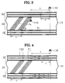
- FIG.3 is a schematic diagram of the recording format of the magnetic tape for the digital video signal recording and reproducing apparatus according to the present invention.
- reference numeral 30 represents a first region for normal recording and playback operations
- reference numeral 32 represents a second region for a special playback such as a high speed search.
- the first region 30 includes a plurality of sloped tracks Ts on which the digital audio/video information and the tracking pilot signal are overlapped and recorded via the helical scan-type rotary head.
- the second regions 32 include at least one horizontal track Th on which the special reproduction picture information is recorded via fixed heads 136. Fixed heads 136 are positioned at the distance "X" (same as that of the conventional VTR) from the scanning end of sloped track Ts of rotary heads 116.
- the position of the fixed heads corresponds to that of the audio & cue head assembly of the conventional VTR. Therefore, when rotary heads 116 scans a quantity N of sloped track Ts of first region 30, an interval "Y" along horizontal track Th of tape 10 is scanned by fixed heads 136. Accordingly, in the present invention, one frame of information is recorded on the interval "Y" of horizontal track Th so as to correspond to a predetermined number of frames at a normal recording speed. For special playback operations, the picture information recorded on the horizontal track is picked up and reproduced via the fixed head, while the tape is travelled at a predetermined playback speed.
- FIG.4 shows a tape recording format according to one preferred embodiment of the present invention.
- one frame of information is divisionally recorded on four sloped tracks at a speed of 30 frames per second, and simultaneously, two frames of information is divisionally recorded on four horizontal tracks.
- FIG.4 when 30 frames of information F1-F30 is recorded on first region 30 for one second, two frames of information F1-F16 having a fifteen-frame interval is recorded on the interval "Y" of second region 32 for one second.
- FIG.5 is block diagram of the recording and reproducing apparatus according to one embodiment of the present invention.
- the apparatus of the present invention can be categorized into a recorder section and a reproducer section, with the recorder being subdivided into a normal recorder and special recorder and the reproducer likewise being subdivided into a normal reproducer and special reproducer.
- the normal recorder comprises sub-sampling circuit 102, data compression circuit 104, error correction encoder 106, audio encoder 108, channel encoder 110 and recording amplifier 112.
- the special recorder comprises source input format (SIF) sub-sampling circuit 122, data compression circuit 124, channel division circuit (or multiplexer) 126, four error correction encoders 128, four channel encoders 130, and four channel recording amplifiers 132.
- SIF source input format
- the normal reproducer comprises reproduction amplifier 202, channel decoder 204, error correction decoder 206, audio decoder 208, data decompression circuit 210 and interpolator 212.
- the special reproducer comprises four reproduction amplifiers 222, four channel decoders 224, four error correction decoders 226, channel restoration circuit (or demultiplexer) 228, data decompression circuit 230 and interpolator 232.
- the normal recorder and the normal reproducer are combined with a pair of rotary heads 116 via switch 114.
- the special recorder and the special reproducer are combined with four fixed heads via switch 134.
- the special recorder inputs one frame of information by an interval of fifteen frames via switch SW1.
- the special reproducer selects the size of the screen display for the reproduced picture via switch SW2.
- the reproduced picture can be displayed as a full-sized screen via interpolator 232; without passing through the interpolator, the reproduced picture is displayed on a quarter-sized screen.
- picture quality is partially sacrificed when the SIF sub-sampled picture is interpolated as a full screen display, and a quarter screen display is somewhat small but produces better picture quality.
- the background is processed as a blue screen or such like.
- the luminance signal Y is composed of 480 ⁇ 720 pixels, and each color difference signal is 480 ⁇ 360 pixels.
- sub-sampling circuit 102 receives 4:2:2 component signal and sub-samples the color difference signals Cr and Cb, so as to be converted into a 4:1:1 component signal.
- Data compressor 104 receives the converted signal, compresses the data in a predetermined compression ratio, encodes the compressed data, and outputs the encoded data.
- the compression encoding method uses a well-known orthogonal transform coding, predictive coding or vector quantization; intraframe or interframe coding is also possible.
- Error correction encoder 106 receives the encoded data and encodes the received data by a well-known error correction encoding algorithm, to output the data added in sync-block units to the parity code.
- a two-byte sync code (SYNC) and two-byte identification code (ID) are added to the data of the sync block.
- the data output from audio encoder 108 is processed therein by such digital modulation methods as eight-to-eight, eight-to-fourteen or quadrature-amplitude modulation.
- Recording amplifier 112 amplifies the modulated data and supplies the amplified data to rotary head 116 via switch 114. If the final recording bit rate is 25Mbps and the rotary drum having a diameter of 40min is rotated at 3600rpm, the rotary speed of rotary head 116 is 7.536m/s and the maximum recording frequency becomes 12.5MHz.
- the special recorder processes the information corresponding to thirty frames which is processed for one second in the normal recorder, and records the processed data on the interval "Y" of the horizontal track via fixed heads 136.
- the interval "Y" is a very small region compared with the normal recording region, the information corresponding to the entire thirty frames cannot be recorded, and one frame of information can be recorded by intervals of fifteen frames or thirty frames.
- This embodiment is described with respect to one frame of information being recorded by an interval of fifteen frames. Therefore, as shown in FIG.4, the information corresponding to frames F1 and F16 among the thirty frames is compressed and recorded on the interval "Y."
- Switch means SW1 is turned on for a one-frame period every other 15-frame interval, and is turned off for the other periods.
- SIF sub-sampling means 122 sub-samples the 4:2:2 component signal, and converts the luminance signal Y into a signal of 240 ⁇ 360 pixels and each color difference signal Cr and Cb into one of 120 ⁇ 180 pixels. This is for reducing the data amount through the sub-sampling, since the amount of bits which can be recorded on the interval "Y" is much less than that needed for normal recording. Since data compression circuit 124 has no interframe correlation, only the intraframe encoding method is applicable. The bit amount is constantly controlled in frame units, using a well-known compression encoding method.
- a data compression ratio CP is represented as the following equation (2).
- a reference symbol B represents a bit rate per each channel
- C is a parity bit rate
- ⁇ is the recording wavelength of a fixed head
- H is the number of fixed heads
- ⁇ T is the relative speed of the tape with respect to a fixed head.
- the compression ratio CP is calculated thus: Therefore, the bit rate after compression is 155.77kbps (2025kbps/13). Accordingly, in this embodiment, one frame of SIF information should be always constantly compressed as 77.88kbps.
- the above compression ratio has been calculated on the basis of a standard-play mode. However, in case of a long-play mode, since the speed of the drum rotation is 1800rpm, the number of tracks per frame is reduced from four to two, and accordingly, the interval "Y" is halved. Thus, the compression ratio should be double for the long-play mode.
- the relationship between the data compression ratio and certain parameters for the special recorder is as follows:
- the system according to the present invention is optimally designed based on the data compression CP. P, ⁇ and H.
- the compression ratio calculation should be decided taking costs into consideration along with the widths of the both auxiliary tracks.
- Channel division circuit 126 divides the compressively encoded data into four channels of data for output.
- the respectively divided channel data is supplied to the corresponding fixed heads 136 through error correction encoders 128, channel encoders 130 and recording amplifiers 132.
- the signal is picked up from a first region of sloped tracks via rotary head 116 and input to the normal reproducer via switch means 114.
- the signal input to the normal reproducer passes through reproduction amplifier 202 and channel decoder 204, and the channel-decoded video data passes through error correction decoder 206, data decompression circuit 210 and interpolator 212, so as to be reconstructed as an original picture signal and supplied to a display unit.
- the channel-decoded audio data is restored as an audio signal via audio decoder 208.
- the signal is picked up from a second region of horizontal tracks via four fixed heads 136 and input to the special reproducer via switch means 134.
- the tape speed is increased.
- one frame of information which is simultaneously picked up from four fixed heads 136 should be processed within 1/30th of a second.
- the tape travels 7.053mm (14.106mm/2), making the tape speed 211.59mm/s.
- the information is sequentially picked up in the order of F1, F16, F31..., which ultimately performs fifteen-times speed reproduction.
- the special reproducer processes the input signal in the reverse order of that for the special recorder, to reconstruct the original signal having the SIF form. Accordingly, the restored signal is interpolated and converted back into a CCIR 601 format via interpolator 232 to be displayed as a full-sized screen, or is output directly in SIF form to be displayed as a half-sized screen.
- a half-loading method as shown in FIG.8 can be applied to the tape.
- the half-loading method is advantageous over the full-loading method in view of the loosening of the tape and its deterioration due to wear.
- the frequency characteristics for the recording and reproducing procedure of the fixed heads can be described as follows.
- the bit amount which is able to be recorded for a second by a single fixed head is 46.7Kbits. Accordingly, in case of the fifteen-times speed, the bit rate is 700.5Kbits (46.7Kbits ⁇ 15). Therefore, since the maximum frequency is 0.34MHz, the frequency characteristic of the fixed head is designed so as to be more than 0.34MHz.
- FIG.9 represents the data recording format of a time when one frame of information is recorded on the interval "Y," that is, the recording format of a time when one frame of information is recorded on an interval "Y" of the horizontal track for the purpose of the special reproduction every other thirty-frame interval.
- the data compression ratio becomes 6.5. which halves the compression ratio burden compared with the above-described Y-interval double-frame method.
- the Y-interval single-frame method has a tape reproduction speed of 423.18mm (14.106mm divided by 1/30th of a second). Thus, only 30-times speed is possible. Therefore, in this case, the frequency characteristic of the fixed head becomes 0.68MHz.
- FIG.10 is a block diagram of a video output means for a variable speed reproduction of a recording and reproducing system according to the present invention.
- reference symbols M1 and M2 are frame memories
- SW3 and SW4 are switches.
- Switch SW3 alternately supplies the frame information restored in the special reproducer to frame memories M1 and M2.
- Switch SW4 performs a switching of frame memories M1 and M2 opposite that of switch SW3.
- the supplied frame information is written on frame memories M1 and M2 for a time which is the reciprocal of the product of the number of Y-interval-recorded frames and the speed multiple.
- the written frame information is repetitively read out from frame memories M1 and M2 by an integer value representing the write time (per second) multiplied by thirty (30/s).
- the tape is travelled at a speed of n ⁇ T .
- the memory write time is (1/mn)th of a second and the number of read repetitions is 30 ⁇ (1/mn).
- the present invention records the data for the normal recording and reproduction and that for the special recording and reproduction separately, on mutually different regions of the magnetic tape in a digital VTR. Accordingly, since the processing of the normal recording/reproduction signal is independent from that of the special recording/reproduction signal, the normal-processing design is facilitated with a higher degree of freedom. Also, the special-processing design is possible using general-purpose VTR technology without the need for high-precision servo technology and without the use of special materials and/or components.
- every Nth frame of data recorded on the second region corresponds to every Nth frame of normal recording.
- the data is partly extracted from a plurality of frames of the normal recording.
- every Nth frame of data recorded on the second region can be constituted. That is, in the case of a single-frame four-segment four-track method, the Y-interval is divided into four segments, so that a first segment S1 of first frame F1, a second segment S2 of second frame F2, a third segment S3 of third frame F3 and a fourth segment S4 of fourth frame F4 can be sequentially recorded. Therefore, in the case of the Y-interval single-frame method, the Y-interval is divided into thirty segments. The data partially extracted from each of the thirty frames can be respectively recorded on the divided segments.
Abstract
Description
- The present invention relates to a digital video signal recording and reproducing method and apparatus thereof, and more particularly, relates to a digital video signal recording and reproducing method and apparatus thereof for providing an excellent reproduction picture when performing a variable speed reproduction such as a high speed search.
- Since 1980, home appliance manufacturers have been studying and developing digital video tape recorders (VTRs) for home usage. Such digital VTR systems are for simply recording and reproducing video data by means of compression and high-density recording, and should accomplish an encoding technology which simultaneously achieves high definition, long recording times, variable speed reproduction, and picture editing. However, when video data is compressed for extended duration recording, the compression bit rate is varied according to the complexity of the video. Accordingly, the bit rate should be fixed in units of a sync block, being the minimum unit to satisfy high definition. Therefore, since some data is lost by the fixed bit rate, a completely satisfactory picture cannot be expected. Also, even if the bit rate is fixed to a sync-block unit, when the sync-block data is not totally picked up, hence, the sync block is not reproducible. Accordingly, since the unproducible sync block is generated during a variable speed reproduction in which the rotary head transverses a track, the mosaic phenomenon randomly appears on the screen according to the multiple speed. Thus, the picture quality of the variable speed reproduction screen is less than desirable.
- To obtain a sharp picture during variable speed reproduction, a method of jumping over the tracks has been developed by adopting a dynamic head using a piezoelectric element such as a bimorph cell. According to the present technology level, the method enables reproduction at three to five times normal speed, while reproduction at more than six times the normal speed is impossible. Also, since the dynamic head is expensive and the servo control technology of track jumping requires very high precision, this method is currently used only in special applications such as a broadcast studio.
- Therefore, to solve the above problems of the conventional technologies, it is an object of the present invention to provide a digital video signal recording and reproducing method in which, during a variable speed reproduction, a clear picture can be viewed.
- It is another object of the present invention to provide a digital video recording and reproducing apparatus which is most adaptable for performing the above digital video recording and reproducing method.
- To accomplish the above first-mentioned object of the present invention, there is provided a digital video recording and reproducing method comprising the steps of:
helically scanning a first region of a magnetic tape running at a normal speed, using a plurality of rotary heads:
recording a digital data train on a plurality of sloped tracks, and simultaneously recording a single frame of data at an interval of N pictures on a second region of the magnetic tape, through at least one fixed head; and
reproducing the data recorded on the first region during a normal reproduction, while the magnetic tape runs at an N-times speed for a variable speed reproduction to reproduce the data recorded on the second region. - To accomplish the above second-mentioned object of the invention, there is provided a digital video recording and reproducing apparatus comprising:
a plurality of rotary heads for helically scanning a first region of a magnetic tape, at a predetermined rotating speed:
a plurality of fixed heads for lengthwise scanning a second region of the magnetic tape:
a normal recording portion which receives a digital audio/video signal, performs high-efficiency encoding, error correction encoding and channel encoding of the received signal, and supplies the encoded signal to the plurality of rotary heads;
a variable speed recording portion which receives every Nth frame of the digital video signal input to the normal recording portion, performs sub-sampling, high-efficiency encoding and channel division operations to the input signal, performs error correction encoding and channel encoding of the respectively divided channel signals and supplies the encoded and divided signal to the corresponding fixed heads;
a normal reproduction portion which processes the signals picked-up from the first region of the magnetic tape via the plurality of the rotary heads in the manner inverse that of the recording procedure and restores the processed signals into the original signals, during the normal reproduction; and
a variable speed reproduction portion which processes the signals picked-up from the second region of the magnetic tape via the plurality of the fixed heads in the inverse manner that of the recording procedure and restores the processed signals into the original signals, during the variable speed reproduction. - The above objects and other advantages of the present invention will become more apparent by describing in detail preferred embodiments of the present invention with reference to the attached drawings in which:
- FIG.1 is a recording pattern diagram showing a conventional helical scan-type 8mm video tape;
- FIG.2 is a schematic diagram showing a tape running system of a conventional helical scan-type video tape recorder (VTR);
- FIG.3 is a recording pattern diagram of a magnetic tape according to the present invention;
- FIG.4 is a recording pattern diagram of a magnetic tape according to a preferred embodiment of the present invention;
- FIG.5 is block diagram of a recording and reproducing apparatus according to the present invention;
- FIG.6 is a view for explaining displayed picture size when a special reproduction is performed according to the present invention;
- FIG.7 is a view for explaining a sub-sampling operation when a special recording is performed according to the present invention;
- FIG.8 is a view for explaining a half-loading method when a special reproduction is performed according to the present invention;
- FIGs.9 is a recording pattern diagram of a magnetic tape according to another embodiment of the present invention;
- FIG. 10 is a block diagram which represents a video output means for a variable speed reproduction according to the present invention; and
- FIG.11 is a recording pattern diagram of a magnetic tape according to yet another embodiment of the present invention.
- The preferred embodiments of the present invention will be described below with reference to the accompanying drawings.
- FIG.1 shows a recording format for a conventional helical scan-type 8mm video tape. Here, a reference symbol "A" represents the overall width (8mm) of the video tape, "R" is the dimension (0.6mm) of an auxiliary audio track Ta, "C" is the dimension (0.6mm) of a cue track Tc, "X" is the distance (31mm) along the tape from the 180° scan end location for a rotary drum to the position of audio and cue heads Ha and Hc, and "Ts" is a sloped track divided into audio and video data intervals. Sloped track Ts is inclined by a lead angle ϑ with respect to the lengthwise direction of the tape. Also in FIG.1, 36° of the rotary drum scan is allotted for the audio data, while the 5° is for the vertical blanking period.
- FIG.2 is a schematic diagram of a tape running system of the general helical scanning rotary head-type digital VTR. In FIG.2,
reference numeral 10 represents a tape, 12 is a rotary drum, 12a and 12b are rotary heads, 14 and 16 are inclined posts, 18 is an erase head assembly, 20 is a cue & audio head assembly, 22 is a capstan shaft, and 24 is a pinch roller.Tape 10 is travelled at a constant running velocity νT bycapstan shaft 22 andpinch roller 24 which are rotated by a capstan motor (not shown). Rotary drum 12 is rotated in a constant rotational velocity νD (i.e.. 3600rpm) by a drum motor (not shown). For instance, assuming that the diameter of the rotary drum is 40mm,rotary heads 
Here, NTs represents the number of sloped tracks scanned per one second by the rotary head. For example, in the case of a single-frame four-track division method, 30 frames should be displayed on a screen each second. Accordingly, since 120 tracks are scanned per second by the rotary head, tape running velocity νT becomes 14.106mm/s. That is,tape 10 is travelled by 14.106 millimeters per second in the lengthwise direction of the tape. - Thus, the present invention can record and reproduce the particular reproduction picture information (e.g., trick play or a variable speed reproduction operation) on the audio track Ta and cue track Tc, thereby displaying a clean picture during the special playback operation. Also, since the normal reproduction region is independent from the special reproduction region, the bit rate of the video data to be recorded on the normal reproduction region can be fixed. Accordingly, the picture quality of the normal reproduction picture is improved and the composition of the data compression and decompression circuitry can be simplified.
- FIG.3 is a schematic diagram of the recording format of the magnetic tape for the digital video signal recording and reproducing apparatus according to the present invention. In FIG.3,
reference numeral 30 represents a first region for normal recording and playback operations, andreference numeral 32 represents a second region for a special playback such as a high speed search. Thefirst region 30 includes a plurality of sloped tracks Ts on which the digital audio/video information and the tracking pilot signal are overlapped and recorded via the helical scan-type rotary head. Thesecond regions 32 include at least one horizontal track Th on which the special reproduction picture information is recorded viafixed heads 136. Fixedheads 136 are positioned at the distance "X" (same as that of the conventional VTR) from the scanning end of sloped track Ts ofrotary heads 116. That is, here, the position of the fixed heads corresponds to that of the audio & cue head assembly of the conventional VTR. Therefore, when rotary heads 116 scans a quantity N of sloped track Ts offirst region 30, an interval "Y" along horizontal track Th oftape 10 is scanned by fixedheads 136. Accordingly, in the present invention, one frame of information is recorded on the interval "Y" of horizontal track Th so as to correspond to a predetermined number of frames at a normal recording speed. For special playback operations, the picture information recorded on the horizontal track is picked up and reproduced via the fixed head, while the tape is travelled at a predetermined playback speed. - Preferred embodiments of the present invention will be described below for the sake of the understanding of the invention.
- FIG.4 shows a tape recording format according to one preferred embodiment of the present invention. In this embodiment, one frame of information is divisionally recorded on four sloped tracks at a speed of 30 frames per second, and simultaneously, two frames of information is divisionally recorded on four horizontal tracks. Thus, as shown in FIG.4, when 30 frames of information F1-F30 is recorded on
first region 30 for one second, two frames of information F1-F16 having a fifteen-frame interval is recorded on the interval "Y" ofsecond region 32 for one second. - FIG.5 is block diagram of the recording and reproducing apparatus according to one embodiment of the present invention. The apparatus of the present invention can be categorized into a recorder section and a reproducer section, with the recorder being subdivided into a normal recorder and special recorder and the reproducer likewise being subdivided into a normal reproducer and special reproducer.
- The normal recorder comprises
sub-sampling circuit 102,data compression circuit 104,error correction encoder 106,audio encoder 108,channel encoder 110 andrecording amplifier 112. Meanwhile, the special recorder comprises source input format (SIF)sub-sampling circuit 122,data compression circuit 124, channel division circuit (or multiplexer) 126, fourerror correction encoders 128, fourchannel encoders 130, and fourchannel recording amplifiers 132. - The normal reproducer comprises
reproduction amplifier 202,channel decoder 204,error correction decoder 206,audio decoder 208,data decompression circuit 210 and interpolator 212. Meanwhile, the special reproducer comprises fourreproduction amplifiers 222, fourchannel decoders 224, fourerror correction decoders 226, channel restoration circuit (or demultiplexer) 228,data decompression circuit 230 andinterpolator 232. - The normal recorder and the normal reproducer are combined with a pair of
rotary heads 116 viaswitch 114. The special recorder and the special reproducer are combined with four fixed heads viaswitch 134. The special recorder inputs one frame of information by an interval of fifteen frames via switch SW1. The special reproducer selects the size of the screen display for the reproduced picture via switch SW2. - As shown in FIG.5, the reproduced picture can be displayed as a full-sized screen via
interpolator 232; without passing through the interpolator, the reproduced picture is displayed on a quarter-sized screen. Under these conditions, picture quality is partially sacrificed when the SIF sub-sampled picture is interpolated as a full screen display, and a quarter screen display is somewhat small but produces better picture quality. In the peripheral region of the quarter-screen display, the background is processed as a blue screen or such like. - In the above apparatus, the video input is a component signal having the CCIR 601 format in which the ratio of Y:Cr:Cb = 4:2:2, as can be seen in FIG.7. Here, the luminance signal Y is composed of 480×720 pixels, and each color difference signal is 480×360 pixels.
- Referring to FIGs.5, 6 and 7,
sub-sampling circuit 102 receives 4:2:2 component signal and sub-samples the color difference signals Cr and Cb, so as to be converted into a 4:1:1 component signal.Data compressor 104 receives the converted signal, compresses the data in a predetermined compression ratio, encodes the compressed data, and outputs the encoded data. Here, the compression encoding method uses a well-known orthogonal transform coding, predictive coding or vector quantization; intraframe or interframe coding is also possible. - It should be noted that for the above special reproduction function, the conventional problem has persisted in that controlling so as to fix the amount of bits of the sync block as the minimum recording unit is difficult; and for this reason, picture quality has suffered greatly. However, since the special reproduction data is separately processed in the present invention, the amount of bits does not need to be strictly controlled. Accordingly, since the compression algorithm becomes simplified, a simple compression circuit can be constructed.
- As the bit rate may be fixed in units of fifteen frames or thirty frames in the present invention, the picture quality of the reproduced picture during the normal reproduction is much improved compared with the conventional case.
Error correction encoder 106 receives the encoded data and encodes the received data by a well-known error correction encoding algorithm, to output the data added in sync-block units to the parity code. A two-byte sync code (SYNC) and two-byte identification code (ID) are added to the data of the sync block. The data output fromaudio encoder 108 is processed therein by such digital modulation methods as eight-to-eight, eight-to-fourteen or quadrature-amplitude modulation.Recording amplifier 112 amplifies the modulated data and supplies the amplified data torotary head 116 viaswitch 114. If the final recording bit rate is 25Mbps and the rotary drum having a diameter of 40min is rotated at 3600rpm, the rotary speed ofrotary head 116 is 7.536m/s and the maximum recording frequency becomes 12.5MHz. - The special recorder processes the information corresponding to thirty frames which is processed for one second in the normal recorder, and records the processed data on the interval "Y" of the horizontal track via fixed heads 136. However, since the interval "Y" is a very small region compared with the normal recording region, the information corresponding to the entire thirty frames cannot be recorded, and one frame of information can be recorded by intervals of fifteen frames or thirty frames. This embodiment is described with respect to one frame of information being recorded by an interval of fifteen frames. Therefore, as shown in FIG.4, the information corresponding to frames F1 and F16 among the thirty frames is compressed and recorded on the interval "Y." Switch means SW1 is turned on for a one-frame period every other 15-frame interval, and is turned off for the other periods. As shown in FIG.7, SIF sub-sampling means 122 sub-samples the 4:2:2 component signal, and converts the luminance signal Y into a signal of 240×360 pixels and each color difference signal Cr and Cb into one of 120×180 pixels. This is for reducing the data amount through the sub-sampling, since the amount of bits which can be recorded on the interval "Y" is much less than that needed for normal recording. Since
data compression circuit 124 has no interframe correlation, only the intraframe encoding method is applicable. The bit amount is constantly controlled in frame units, using a well-known compression encoding method. Here, a data compression ratio CP is represented as the following equation (2).
Here, a reference symbol B represents a bit rate per each channel, C is a parity bit rate, λ is the recording wavelength of a fixed head, H is the number of fixed heads, and νT is the relative speed of the tape with respect to a fixed head. - Using the above equation (2) and assuming that a total bit rate of two SIF sub-sampled frames is 2025kbps, the parity bit rate is 20% of the total bit rate, λ is 0.6µm, and νT is 14.106mm/s, the compression ratio CP is calculated thus:

Therefore, the bit rate after compression is 155.77kbps (2025kbps/13). Accordingly, in this embodiment, one frame of SIF information should be always constantly compressed as 77.88kbps. - The above compression ratio has been calculated on the basis of a standard-play mode. However, in case of a long-play mode, since the speed of the drum rotation is 1800rpm, the number of tracks per frame is reduced from four to two, and accordingly, the interval "Y" is halved. Thus, the compression ratio should be double for the long-play mode. Here, the relationship between the data compression ratio and certain parameters for the special recorder is as follows:
- i) Sloped track pitch P: As P increases, the interval "Y" becomes longer. (Accordingly, the burden to the compression ratio is reduced and the normal recording time is shortened.)
- ii) Recording wavelength λ: As λ grows shorter, the recording density increases. (The present level of the technology is about 0.6µm.)
- iii) Number of fixed heads H: As H increases, the compression ratio is reduced.
- As described above, the system according to the present invention is optimally designed based on the data compression CP. P, λ and H. The compression ratio calculation should be decided taking costs into consideration along with the widths of the both auxiliary tracks.
-
Channel division circuit 126 divides the compressively encoded data into four channels of data for output. The respectively divided channel data is supplied to the corresponding fixedheads 136 througherror correction encoders 128,channel encoders 130 andrecording amplifiers 132. - The reproducing system according to the present invention is described below. During normal reproduction, the signal is picked up from a first region of sloped tracks via
rotary head 116 and input to the normal reproducer via switch means 114. The signal input to the normal reproducer passes throughreproduction amplifier 202 andchannel decoder 204, and the channel-decoded video data passes througherror correction decoder 206,data decompression circuit 210 and interpolator 212, so as to be reconstructed as an original picture signal and supplied to a display unit. The channel-decoded audio data is restored as an audio signal viaaudio decoder 208. On the other hand, during special reproduction, the signal is picked up from a second region of horizontal tracks via four fixedheads 136 and input to the special reproducer via switch means 134. - In the present invention, during such special reproduction functions as high-speed searching, the tape speed is increased. Here, to accomplish real-time processing even during a high speed reproduction, one frame of information which is simultaneously picked up from four fixed
heads 136 should be processed within 1/30th of a second. During this processing, the tape travels 7.053mm (14.106mm/2), making the tape speed 211.59mm/s. With the tape travelling at such a speed, the information is sequentially picked up in the order of F1, F16, F31..., which ultimately performs fifteen-times speed reproduction. The special reproducer processes the input signal in the reverse order of that for the special recorder, to reconstruct the original signal having the SIF form. Accordingly, the restored signal is interpolated and converted back into a CCIR 601 format viainterpolator 232 to be displayed as a full-sized screen, or is output directly in SIF form to be displayed as a half-sized screen. - Also, in the high speed reproduction, besides the full-loading method (FIG.2), a half-loading method as shown in FIG.8 can be applied to the tape. The half-loading method is advantageous over the full-loading method in view of the loosening of the tape and its deterioration due to wear.
- The frequency characteristics for the recording and reproducing procedure of the fixed heads can be described as follows.
- The bit amount which is able to be recorded for a second by a single fixed head is 46.7Kbits. Accordingly, in case of the fifteen-times speed, the bit rate is 700.5Kbits (46.7Kbits × 15). Therefore, since the maximum frequency is 0.34MHz, the frequency characteristic of the fixed head is designed so as to be more than 0.34MHz.
- FIG.9 represents the data recording format of a time when one frame of information is recorded on the interval "Y," that is, the recording format of a time when one frame of information is recorded on an interval "Y" of the horizontal track for the purpose of the special reproduction every other thirty-frame interval. In this case, the data compression ratio becomes 6.5. which halves the compression ratio burden compared with the above-described Y-interval double-frame method. On the other hand, the Y-interval single-frame method has a tape reproduction speed of 423.18mm (14.106mm divided by 1/30th of a second). Thus, only 30-times speed is possible. Therefore, in this case, the frequency characteristic of the fixed head becomes 0.68MHz.
- FIG.10 is a block diagram of a video output means for a variable speed reproduction of a recording and reproducing system according to the present invention. Here, reference symbols M1 and M2 are frame memories, and SW3 and SW4 are switches. Switch SW3 alternately supplies the frame information restored in the special reproducer to frame memories M1 and M2. Switch SW4 performs a switching of frame memories M1 and M2 opposite that of switch SW3. The supplied frame information is written on frame memories M1 and M2 for a time which is the reciprocal of the product of the number of Y-interval-recorded frames and the speed multiple. Also, the written frame information is repetitively read out from frame memories M1 and M2 by an integer value representing the write time (per second) multiplied by thirty (30/s). For example, using the Y-interval single-frame method (FIG.9), variable-speed reproduction at the speeds shown in the following Table 1 is possible.
TABLE 1 Speed multiple Tape speed (mm/s) Write time (in seconds) Read time (in seconds) Number of read repetitions 1× 1ν T1 1/30 30 2× 2ν T1/2 1/30 15 3× 3ν T1/3 1/30 10 5× 5ν T1/5 1/30 6 6× 6ν T1/6 1/30 5 10× 10ν T1/10 1/30 3 15× 15ν T1/15 1/30 2 30× 30ν T1/30 1/30 1 - Further, using the Y-interval double-frame method (FIG.4), variable-speed reproduction at the speeds shown in the below Table 2 is possible.
TABLE 2 Speed multiple Tape speed (mm/s) Write time (in seconds) Read time (in seconds) Number of read repetitions 1× ν T1/2 1/30 15 3× 3ν T1/6 1/30 5 5× 5ν T1/10 1/30 3 15× 15ν T1/30 1/30 1 - Thus, when performing the m-times speed in the Y-interval m-frame method, the tape is travelled at a speed of n×νT. Here, the memory write time is (1/mn)th of a second and the number of read repetitions is 30×(1/mn).
- As described above, the present invention records the data for the normal recording and reproduction and that for the special recording and reproduction separately, on mutually different regions of the magnetic tape in a digital VTR. Accordingly, since the processing of the normal recording/reproduction signal is independent from that of the special recording/reproduction signal, the normal-processing design is facilitated with a higher degree of freedom. Also, the special-processing design is possible using general-purpose VTR technology without the need for high-precision servo technology and without the use of special materials and/or components.
- In the present invention, a method for making every Nth frame of data recorded on the second region correspond to every Nth frame of normal recording has been illustrated. However, as shown in FIG.11, the data is partly extracted from a plurality of frames of the normal recording. In this manner, every Nth frame of data recorded on the second region can be constituted. That is, in the case of a single-frame four-segment four-track method, the Y-interval is divided into four segments, so that a first segment S1 of first frame F1, a second segment S2 of second frame F2, a third segment S3 of third frame F3 and a fourth segment S4 of fourth frame F4 can be sequentially recorded. Therefore, in the case of the Y-interval single-frame method, the Y-interval is divided into thirty segments. The data partially extracted from each of the thirty frames can be respectively recorded on the divided segments.
Claims (19)
- A digital video recording and reproducing method comprising the steps of:
helically scanning a first region of a magnetic tape running at a normal speed, using a plurality of rotary heads;
recording a digital data train on a plurality of sloped tracks, and simultaneously recording single frame data at an interval of N pictures on a second region of the magnetic tape, through at least one fixed head; and
reproducing the data recorded on the first region during a normal reproduction, while the magnetic tape runs at an N-times speed for a variable speed reproduction to reproduce the data recorded on the second region. - The digital video signal recording and reproducing method according to claim 1, wherein said digital data train recorded on said first region is separately recorded on M sloped tracks for every frame.
- The digital video signal recording and reproducing method according to claim 2, wherein said Nth frame data is recorded on at least one horizontal track within an interval through which said magnetic tape is travelled when the Nth to (2N - 1)th frame data is recorded on said first region.
- The digital video signal recording and reproducing method according to claim 3, wherein said travelled distance (Y) is expressed

- The digital video signal recording and reproducing method according to claim 1, wherein said digital data train recorded on said first region has a bit rate fixed in units of N frames.
- The digital video signal recording and reproducing method according to claim 3, wherein said every Nth frame data recorded on said second region has a bit rate fixed in units of a frame.
- The digital video signal recording and reproducing method according to claim 3, wherein a data compression ratio (CP) is expressed

- The digital video signal recording and reproducing method according to claim 1, wherein the number of said fixed heads is four.
- The digital video signal recording and reproducing method according to claim 1, wherein said every Nth frame data to be recorded on said second region is obtained by SIF-subsampling the original picture data.
- The digital video signal recording and reproducing method according to claim 9, wherein said every Nth frame data reproduced during the variable reproduction is interpolated and displayed into the size of the original picture.
- The digital video signal recording and reproducing method according to claim 9, wherein said every Nth frame data reproduced during the variable reproduction is displayed into the size of the sub-sampled picture.
- The digital video signal recording and reproducing method according to claim 1, wherein said every Nth frame data reproduced during the variable reproduction is recorded in the frame memory at a recording rate of 1/mn, and said recorded data is repetitively reproduced by an integer representing the value of 30×(1/mn) per second, in which n represents the number of frames recorded on the horizontal track per unit of time and m represents the speed multiple.
- A digital video recording and reproducing method comprising the steps of:
helically scanning a first region of a magnetic tape running at a normal speed, using a plurality of rotary heads:
recording a digital data train of 30 frames per second on a plurality of sloped tracks, and simultaneously picking up the digital data from at least one frame among said 30 frames:
recording at least one frame of a digital data train formed of the picked-up digital data on at least one horizontal track in a second region of the magnetic tape through at least one fixed head; and
reproducing the data recorded on the first region during a normal reproduction, while the magnetic tape runs at an predetermined multiple speed during a variable speed reproduction, to reproduce the data recorded on the second region. - A digital video recording and reproducing apparatus comprising:
a plurality of rotary heads for helically scanning a first region of a magnetic tape at a predetermined rotation speed;
a plurality of fixed heads for lengthwise scanning a second region of the magnetic tape;
a normal recording portion which receives a digital audio/video signal, performs high efficiency encoding, error correction encoding and a channel encoding of the received signal, and supplies the encoded signal to the plurality of rotary heads;
a variable speed recording portion which receives every Nth frame of the digital video signal input to the normal recording portion, performs sub-sampling, high-efficiency encoding and channel division of the input signal, performs error correction encoding and channel encoding of the respective divided channel signals and supplies the thus-processed signal to the corresponding fixed heads;
a normal reproduction portion which processes the signals picked-up from the first region of the magnetic tape via the plurality of the rotary heads in the reverse manner as that of the recording procedure and restores the processed signals into the original signals, during the normal reproduction; and
a variable speed reproduction portion which processes the signals picked-up from the second region of the magnetic tape via the plurality of the fixed heads in the reverse manner as that of the recording procedure and restores the processed signals into the original signals, during the variable speed reproduction. - The digital video recording and reproducing apparatus according to claim 14, wherein said variable speed recording portion comprises a source input format (SIF) sub-sampler for sub-sampling the input signal.
- The digital video recording and reproducing apparatus according to claim 14, wherein said tape is half-loaded to a fixed head during the variable speed reproduction.
- The digital video recording and reproducing apparatus according to claim 15, wherein said variable speed reproduction portion comprises an interpolator for restoring the SIF-subsampled signal into the size of the original picture.
- The digital video recording and reproducing apparatus according to claim 14, wherein said variable speed reproduction portion further comprises video output means which records the restored signal in the frame memory at a recording rate of 1/mn, and the written signal is repetitively read by an integer multiple representing the value of 30×(1/mn) per second, in which n represents the number of frames recorded on the horizontal track per unit of time, and m represents the speed multiple.
- The digital video recording and reproducing apparatus according to claim 18, wherein said video output means comprises:
an input switch for switching the restored signal in units of a frame;
a pair of frame memories on which the frame-unit restored signal supplied via said input switch is written at said recording rate and from which the written signal is read by said integer multiple value, and which function alternately with respect to each other; and
an output switch for operating in units of a frame in the opposite manner of said input switch, so as to alternately output the signals read from said pair of frame memories.
Applications Claiming Priority (2)
| Application Number | Priority Date | Filing Date | Title |
|---|---|---|---|
| KR1019920012524A KR100195071B1 (en) | 1992-07-14 | 1992-07-14 | Method and device for recording/reproducing digital video signals |
| KR9212524 | 1992-07-14 |
Publications (3)
| Publication Number | Publication Date |
|---|---|
| EP0579156A2 true EP0579156A2 (en) | 1994-01-19 |
| EP0579156A3 EP0579156A3 (en) | 1994-07-27 |
| EP0579156B1 EP0579156B1 (en) | 1998-12-16 |
Family
ID=19336303
Family Applications (1)
| Application Number | Title | Priority Date | Filing Date |
|---|---|---|---|
| EP93111147A Expired - Lifetime EP0579156B1 (en) | 1992-07-14 | 1993-07-12 | Digital video signal recording and reproducing method and apparatus thereof |
Country Status (6)
| Country | Link |
|---|---|
| US (1) | US5486931A (en) |
| EP (1) | EP0579156B1 (en) |
| JP (1) | JP3076694B2 (en) |
| KR (1) | KR100195071B1 (en) |
| CN (1) | CN1058826C (en) |
| DE (1) | DE69322551T2 (en) |
Cited By (13)
| Publication number | Priority date | Publication date | Assignee | Title |
|---|---|---|---|---|
| EP0673158A2 (en) * | 1994-03-14 | 1995-09-20 | Matsushita Electric Industrial Co., Ltd. | Method and apparatus for recording and reproducing data |
| GB2288942A (en) * | 1994-04-12 | 1995-11-01 | Mitsubishi Electric Corp | Digital video tape recorder |
| EP0685967A2 (en) * | 1994-05-31 | 1995-12-06 | Matsushita Electric Industrial Co., Ltd. | Compressed television signal recording and reproducing apparatus |
| EP0693858A3 (en) * | 1994-07-18 | 1996-08-14 | Gold Star Co | Variable-speed reproducing method for DVCR |
| EP0692916A3 (en) * | 1994-07-14 | 1996-11-20 | Sharp Kk | A digital recording and reproducing apparatus |
| EP0695088A3 (en) * | 1994-07-29 | 1996-11-27 | Sharp Kk | Video storage type communication device |
| EP0701253A3 (en) * | 1994-08-10 | 1997-03-05 | Matsushita Electric Ind Co Ltd | Encoded data stream recording and reproducing apparatus |
| EP0768801A2 (en) * | 1995-10-10 | 1997-04-16 | Samsung Electronics Co., Ltd. | Digital video tape recording and reproducing method |
| EP0787401A1 (en) * | 1994-10-20 | 1997-08-06 | Thomson Consumer Electronics, Inc. | Trick play stream derivation for pre-recorded digital video recording |
| EP0820200A2 (en) * | 1994-04-12 | 1998-01-21 | Koninklijke Philips Electronics N.V. | Recording and reproduction of trick mode video signal |
| US5867625A (en) * | 1994-10-20 | 1999-02-02 | Thomson Consumer Electronics, Inc. | Digital VCR with trick play steam derivation |
| US6122433A (en) * | 1994-10-20 | 2000-09-19 | Thomson Licensing S.A. | HDTV trick play stream derivation for VCR |
| EP1213930A2 (en) * | 1994-04-13 | 2002-06-12 | Rca Thomson Licensing Corporation | Digital VCR with non-standard speed playback |
Families Citing this family (9)
| Publication number | Priority date | Publication date | Assignee | Title |
|---|---|---|---|---|
| JP3089160B2 (en) * | 1994-05-20 | 2000-09-18 | シャープ株式会社 | Digital recording and playback device |
| US6047100A (en) * | 1994-10-20 | 2000-04-04 | Thomson Licensing S.A. | Trick play stream derivation for pre-recorded digital video recording |
| KR0129947B1 (en) * | 1994-12-30 | 1998-04-18 | 김광호 | Recording and reproducing method of digital video tape for trick play |
| JPH08306135A (en) * | 1995-04-28 | 1996-11-22 | Sony Corp | Signal recording device, signal reproducing device and tape type recording medium |
| DE19610089A1 (en) * | 1996-03-14 | 1997-09-18 | Thomson Brandt Gmbh | Track guidance in longitudinal track recording with a large number of parallel tracks |
| JP3050278U (en) * | 1997-12-27 | 1998-06-30 | 船井電機株式会社 | Video tape player |
| JP3849461B2 (en) * | 2001-06-07 | 2006-11-22 | ソニー株式会社 | Imaging apparatus and imaging method |
| WO2014128616A2 (en) * | 2013-02-22 | 2014-08-28 | Amit Kumar Jain Amit | Method of recording, editing and sharing an agglomeration of videos |
| CN117172205B (en) * | 2023-11-02 | 2024-03-15 | 摩尔线程智能科技(北京)有限责任公司 | Performance analysis method, device, electronic equipment and storage medium |
Citations (3)
| Publication number | Priority date | Publication date | Assignee | Title |
|---|---|---|---|---|
| EP0407970A2 (en) * | 1989-07-12 | 1991-01-16 | Hitachi, Ltd. | Digital video signal reproducing apparatus |
| US5194997A (en) * | 1987-10-06 | 1993-03-16 | Canon Kabushiki Kaisha | Data recording apparatus having sub-code recording function |
| WO1993019556A1 (en) * | 1992-03-20 | 1993-09-30 | Thomson Broadcast | Magnetic medium read and/or write device and videotape recorder containing such devices |
Family Cites Families (12)
| Publication number | Priority date | Publication date | Assignee | Title |
|---|---|---|---|---|
| DE3382105D1 (en) * | 1982-09-10 | 1991-02-14 | Hitachi Ltd | RECORDING AND PLAYING DEVICE FOR A VIDEO TAPE RECORDING DEVICE. |
| DE3787184T2 (en) * | 1986-02-18 | 1993-12-16 | Matsushita Electric Ind Co Ltd | Video signal recording method and device for field recording. |
| JPH0194569A (en) * | 1987-10-06 | 1989-04-13 | Canon Inc | Data recorder |
| JPH07105120B2 (en) * | 1987-10-06 | 1995-11-13 | キヤノン株式会社 | Data recorder |
| JPH0194570A (en) * | 1987-10-06 | 1989-04-13 | Canon Inc | Data recorder |
| JPH0831255B2 (en) * | 1987-10-06 | 1996-03-27 | キヤノン株式会社 | Data recorder |
| JPH01119179A (en) * | 1987-11-02 | 1989-05-11 | Hitachi Ltd | Magnetic recording system |
| US5132807A (en) * | 1988-07-28 | 1992-07-21 | Canon Kabushiki Kaisha | Recording apparatus for recording main information with additional information |
| US5130800A (en) * | 1989-12-28 | 1992-07-14 | North American Philips Corporation | Picture out of picture feature for wide-screen display |
| JPH04151984A (en) * | 1990-10-16 | 1992-05-25 | Toshiba Corp | Video signal recording reproducing method and digital vtr |
| US5347406A (en) * | 1990-10-31 | 1994-09-13 | Sony Corporation | Digital video recording apparatus for recording digital video signals of reduced bit rate on magnetic tape having particular thickness, energy product and surface roughness |
| JP2909239B2 (en) * | 1991-03-27 | 1999-06-23 | 株式会社東芝 | High-efficiency coded recording / reproducing device |
-
1992
- 1992-07-14 KR KR1019920012524A patent/KR100195071B1/en not_active IP Right Cessation
-
1993
- 1993-06-29 JP JP05159198A patent/JP3076694B2/en not_active Expired - Fee Related
- 1993-07-12 EP EP93111147A patent/EP0579156B1/en not_active Expired - Lifetime
- 1993-07-12 DE DE69322551T patent/DE69322551T2/en not_active Expired - Fee Related
- 1993-07-13 CN CN93108378A patent/CN1058826C/en not_active Expired - Fee Related
- 1993-07-14 US US08/091,128 patent/US5486931A/en not_active Expired - Lifetime
Patent Citations (3)
| Publication number | Priority date | Publication date | Assignee | Title |
|---|---|---|---|---|
| US5194997A (en) * | 1987-10-06 | 1993-03-16 | Canon Kabushiki Kaisha | Data recording apparatus having sub-code recording function |
| EP0407970A2 (en) * | 1989-07-12 | 1991-01-16 | Hitachi, Ltd. | Digital video signal reproducing apparatus |
| WO1993019556A1 (en) * | 1992-03-20 | 1993-09-30 | Thomson Broadcast | Magnetic medium read and/or write device and videotape recorder containing such devices |
Cited By (48)
| Publication number | Priority date | Publication date | Assignee | Title |
|---|---|---|---|---|
| EP0933935A1 (en) * | 1994-03-14 | 1999-08-04 | Matsushita Electric Industrial Co., Ltd. | Data recording/reproducing apparatus and data recording/reproducing method |
| CN1305067C (en) * | 1994-03-14 | 2007-03-14 | 松下电器产业株式会社 | Data recording/playback device and method |
| EP0928106A3 (en) * | 1994-03-14 | 1999-09-22 | Matsushita Electric Industrial Co., Ltd. | Data recording/reproducing apparatus and data recording/reproducing method |
| EP0935391A1 (en) * | 1994-03-14 | 1999-08-11 | Matsushita Electric Industrial Co., Ltd. | Data recording/reproducing apparatus and data recording/reproducing method |
| EP0933936A3 (en) * | 1994-03-14 | 1999-08-11 | Matsushita Electric Industrial Co., Ltd. | Data recording/reproducing apparatus and data recording/reproducing method |
| EP0933936A2 (en) * | 1994-03-14 | 1999-08-04 | Matsushita Electric Industrial Co., Ltd. | Data recording/reproducing apparatus and data recording/reproducing method |
| EP0928106A2 (en) * | 1994-03-14 | 1999-07-07 | Matsushita Electric Industrial Co., Ltd. | Data recording/reproducing apparatus and data recording/reproducing method |
| EP0673158A3 (en) * | 1994-03-14 | 1996-04-17 | Matsushita Electric Ind Co Ltd | Method and apparatus for recording and reproducing data. |
| EP0673158A2 (en) * | 1994-03-14 | 1995-09-20 | Matsushita Electric Industrial Co., Ltd. | Method and apparatus for recording and reproducing data |
| US6141487A (en) * | 1994-03-14 | 2000-10-31 | Matsushita Electric Industrial Co., Ltd. | Data recording/reproducing apparatus and method for high speed play |
| US7369746B2 (en) | 1994-04-12 | 2008-05-06 | Mitsubishi Denki Kabushiki Kaisha | Device for recording digital video and audio signals in designated areas of a recording medium in a predetermined track format |
| US6085022A (en) * | 1994-04-12 | 2000-07-04 | Mitsubishi Denki Kabushiki Kaisha | Digital VTR for recording special replay video data in track areas designated for digital video and digital audio |
| US5960150A (en) * | 1994-04-12 | 1999-09-28 | Mitsubishi Denki Kabushiki Kaisha | Digital VTR |
| US5684915A (en) * | 1994-04-12 | 1997-11-04 | Mitsubishi Denki Kabushiki Kaisha | Digital VTR for recording special replay data with appended error correction codes |
| US6339670B1 (en) | 1994-04-12 | 2002-01-15 | Mitsubishi Denki Kabushiki Kaisha | Digital VTR |
| GB2288942B (en) * | 1994-04-12 | 1998-12-09 | Mitsubishi Electric Corp | Digital VTR |
| GB2288942A (en) * | 1994-04-12 | 1995-11-01 | Mitsubishi Electric Corp | Digital video tape recorder |
| EP0820200A2 (en) * | 1994-04-12 | 1998-01-21 | Koninklijke Philips Electronics N.V. | Recording and reproduction of trick mode video signal |
| EP0820200A3 (en) * | 1994-04-12 | 1998-02-25 | Koninklijke Philips Electronics N.V. | Recording and reproduction of trick mode video signal |
| EP1213930A3 (en) * | 1994-04-13 | 2002-06-26 | Rca Thomson Licensing Corporation | Digital VCR with non-standard speed playback |
| EP1213930A2 (en) * | 1994-04-13 | 2002-06-12 | Rca Thomson Licensing Corporation | Digital VCR with non-standard speed playback |
| EP0685967A3 (en) * | 1994-05-31 | 1996-06-05 | Matsushita Electric Ind Co Ltd | Compressed television signal recording and reproducing apparatus. |
| EP0685967A2 (en) * | 1994-05-31 | 1995-12-06 | Matsushita Electric Industrial Co., Ltd. | Compressed television signal recording and reproducing apparatus |
| US6018609A (en) * | 1994-05-31 | 2000-01-25 | Matsushita Electric Industrial Co., Ltd. | Compressed television signal recording and reproducing apparatus |
| US6018611A (en) * | 1994-07-14 | 2000-01-25 | Sharp Kabushiki Kaisha | Recording apparatus which adaptively records amounts of low resolution video inversely to amounts of high resolution video which has the same program content |
| EP0910220A1 (en) * | 1994-07-14 | 1999-04-21 | Sharp Kabushiki Kaisha | A digital recording and reproducing apparatus |
| EP0692916A3 (en) * | 1994-07-14 | 1996-11-20 | Sharp Kk | A digital recording and reproducing apparatus |
| EP0693858A3 (en) * | 1994-07-18 | 1996-08-14 | Gold Star Co | Variable-speed reproducing method for DVCR |
| US7181125B2 (en) | 1994-07-29 | 2007-02-20 | Sharp K.K. | Video storage type communication device |
| EP0982942A3 (en) * | 1994-07-29 | 2000-05-10 | Sharp Kabushiki Kaisha | Video storage type communication device |
| US6360054B1 (en) | 1994-07-29 | 2002-03-19 | Sharp K.K. | Video storage type communication device |
| US6078721A (en) * | 1994-07-29 | 2000-06-20 | Sharp K.K. | Video storage type communication device for selectively providing coded frames for selectable reproduction speed and mode according to type of a terminal device |
| EP0695088A3 (en) * | 1994-07-29 | 1996-11-27 | Sharp Kk | Video storage type communication device |
| EP0982942A2 (en) * | 1994-07-29 | 2000-03-01 | Sharp Kabushiki Kaisha | Video storage type communication device |
| US5841941A (en) * | 1994-08-10 | 1998-11-24 | Matsushita Electric Indstrial Co., Ltd. | Encoded data stream recording and reproducing apparatus with tape speed, channel number, and cylinder speed control in accordance with bit rate |
| EP0701253A3 (en) * | 1994-08-10 | 1997-03-05 | Matsushita Electric Ind Co Ltd | Encoded data stream recording and reproducing apparatus |
| EP0787402A1 (en) * | 1994-10-20 | 1997-08-06 | Thomson Consumer Electronics, Inc. | Hdtv trick play stream derivation for vcr |
| US5867625A (en) * | 1994-10-20 | 1999-02-02 | Thomson Consumer Electronics, Inc. | Digital VCR with trick play steam derivation |
| US6122433A (en) * | 1994-10-20 | 2000-09-19 | Thomson Licensing S.A. | HDTV trick play stream derivation for VCR |
| EP0787409A4 (en) * | 1994-10-20 | 1998-01-07 | Thomson Consumer Electronics | Digital vcr with trick play stream derivation |
| EP0787403A4 (en) * | 1994-10-20 | 1997-12-10 | Thomson Consumer Electronics | Hdtv trick play stream derivation for vcr |
| EP0787401A4 (en) * | 1994-10-20 | 1997-11-19 | Thomson Consumer Electronics | Trick play stream derivation for pre-recorded digital video recording |
| EP0787402A4 (en) * | 1994-10-20 | 1997-08-20 | ||
| EP0787403A1 (en) * | 1994-10-20 | 1997-08-06 | Thomson Consumer Electronics, Inc. | Hdtv trick play stream derivation for vcr |
| EP0787409A1 (en) * | 1994-10-20 | 1997-08-06 | Thomson Consumer Electronics, Inc. | Digital vcr with trick play stream derivation |
| EP0787401A1 (en) * | 1994-10-20 | 1997-08-06 | Thomson Consumer Electronics, Inc. | Trick play stream derivation for pre-recorded digital video recording |
| EP0768801A3 (en) * | 1995-10-10 | 1998-10-14 | Samsung Electronics Co., Ltd. | Digital video tape recording and reproducing method |
| EP0768801A2 (en) * | 1995-10-10 | 1997-04-16 | Samsung Electronics Co., Ltd. | Digital video tape recording and reproducing method |
Also Published As
| Publication number | Publication date |
|---|---|
| JP3076694B2 (en) | 2000-08-14 |
| JPH06209447A (en) | 1994-07-26 |
| KR940002838A (en) | 1994-02-19 |
| DE69322551T2 (en) | 1999-04-29 |
| CN1081528A (en) | 1994-02-02 |
| CN1058826C (en) | 2000-11-22 |
| KR100195071B1 (en) | 1999-06-15 |
| US5486931A (en) | 1996-01-23 |
| EP0579156B1 (en) | 1998-12-16 |
| DE69322551D1 (en) | 1999-01-28 |
| EP0579156A3 (en) | 1994-07-27 |
Similar Documents
| Publication | Publication Date | Title |
|---|---|---|
| US5486931A (en) | Digital video signal recording and reproducing method and apparatus thereof | |
| US5282049A (en) | Moving-picture data digital recording and reproducing apparatuses | |
| JP2650472B2 (en) | Digital signal recording apparatus and digital signal recording method | |
| CA2133710C (en) | Digital video tape recording/reproducing method for trick play | |
| JP3008995B2 (en) | Magnetic recording device for digital video signals | |
| KR100259441B1 (en) | Signal processing apparatus for digital vtr | |
| US5499148A (en) | Digital video tape reproducing apparatus compatible with tapes having a track width different from a rotary magnetic head width | |
| AU9649998A (en) | Data recording apparatus and data recording method, and data editing apparatus and data editing method | |
| US5526124A (en) | Image recording device, image reproducing device, image recording/reproducing device and image recording method | |
| US5864647A (en) | Recording and reproducing apparatus using basic data | |
| JP3348288B2 (en) | Method and apparatus for recording digital video signal | |
| KR100328159B1 (en) | Recording and playback device and playback device | |
| JP2953704B2 (en) | Digital video signal recording and reproducing method | |
| US5519547A (en) | Magnetic recording and reproducing apparatus recording and reproducing plural types of data signals at different data rates | |
| EP0699004B1 (en) | Reproducing digital video signals | |
| KR100200839B1 (en) | Method for recording on a digital video tape for trick play | |
| JP3259324B2 (en) | Digital signal recording device and reproducing device | |
| KR0132832B1 (en) | Recording and reproducing method at digital video tape for trick play | |
| JP3336745B2 (en) | Digital magnetic recording and / or reproducing apparatus | |
| JPH0787434A (en) | Video signal recording device for video signal reproducing device | |
| JPH07274114A (en) | Method and device for reproducing digitally compressed dynamic image at high speed | |
| JPH08336106A (en) | Method and device for recording and reproducing digital image signal |
Legal Events
| Date | Code | Title | Description |
|---|---|---|---|
| PUAI | Public reference made under article 153(3) epc to a published international application that has entered the european phase |
Free format text: ORIGINAL CODE: 0009012 |
|
| AK | Designated contracting states |
Kind code of ref document: A2 Designated state(s): DE FR GB |
|
| PUAL | Search report despatched |
Free format text: ORIGINAL CODE: 0009013 |
|
| AK | Designated contracting states |
Kind code of ref document: A3 Designated state(s): DE FR GB |
|
| 17P | Request for examination filed |
Effective date: 19941228 |
|
| 17Q | First examination report despatched |
Effective date: 19970417 |
|
| GRAG | Despatch of communication of intention to grant |
Free format text: ORIGINAL CODE: EPIDOS AGRA |
|
| GRAG | Despatch of communication of intention to grant |
Free format text: ORIGINAL CODE: EPIDOS AGRA |
|
| GRAH | Despatch of communication of intention to grant a patent |
Free format text: ORIGINAL CODE: EPIDOS IGRA |
|
| GRAH | Despatch of communication of intention to grant a patent |
Free format text: ORIGINAL CODE: EPIDOS IGRA |
|
| GRAA | (expected) grant |
Free format text: ORIGINAL CODE: 0009210 |
|
| AK | Designated contracting states |
Kind code of ref document: B1 Designated state(s): DE FR GB |
|
| REF | Corresponds to: |
Ref document number: 69322551 Country of ref document: DE Date of ref document: 19990128 |
|
| ET | Fr: translation filed | ||
| PLBE | No opposition filed within time limit |
Free format text: ORIGINAL CODE: 0009261 |
|
| STAA | Information on the status of an ep patent application or granted ep patent |
Free format text: STATUS: NO OPPOSITION FILED WITHIN TIME LIMIT |
|
| 26N | No opposition filed | ||
| REG | Reference to a national code |
Ref country code: GB Ref legal event code: IF02 |
|
| PGFP | Annual fee paid to national office [announced via postgrant information from national office to epo] |
Ref country code: DE Payment date: 20080717 Year of fee payment: 16 |
|
| PGFP | Annual fee paid to national office [announced via postgrant information from national office to epo] |
Ref country code: FR Payment date: 20080718 Year of fee payment: 16 |
|
| PGFP | Annual fee paid to national office [announced via postgrant information from national office to epo] |
Ref country code: GB Payment date: 20080716 Year of fee payment: 16 |
|
| GBPC | Gb: european patent ceased through non-payment of renewal fee |
Effective date: 20090712 |
|
| REG | Reference to a national code |
Ref country code: FR Ref legal event code: ST Effective date: 20100331 |
|
| PG25 | Lapsed in a contracting state [announced via postgrant information from national office to epo] |
Ref country code: FR Free format text: LAPSE BECAUSE OF NON-PAYMENT OF DUE FEES Effective date: 20090731 |
|
| PG25 | Lapsed in a contracting state [announced via postgrant information from national office to epo] |
Ref country code: GB Free format text: LAPSE BECAUSE OF NON-PAYMENT OF DUE FEES Effective date: 20090712 |
|
| PG25 | Lapsed in a contracting state [announced via postgrant information from national office to epo] |
Ref country code: DE Free format text: LAPSE BECAUSE OF NON-PAYMENT OF DUE FEES Effective date: 20100202 |