EP0578855A1 - Material for the metallic components of high-temperature fuel cell stacks - Google Patents
Material for the metallic components of high-temperature fuel cell stacks Download PDFInfo
- Publication number
- EP0578855A1 EP0578855A1 EP92112123A EP92112123A EP0578855A1 EP 0578855 A1 EP0578855 A1 EP 0578855A1 EP 92112123 A EP92112123 A EP 92112123A EP 92112123 A EP92112123 A EP 92112123A EP 0578855 A1 EP0578855 A1 EP 0578855A1
- Authority
- EP
- European Patent Office
- Prior art keywords
- yttrium
- temperature
- fuel cell
- solid electrolyte
- material according
- Prior art date
- Legal status (The legal status is an assumption and is not a legal conclusion. Google has not performed a legal analysis and makes no representation as to the accuracy of the status listed.)
- Granted
Links
Images


Classifications
-
- C—CHEMISTRY; METALLURGY
- C22—METALLURGY; FERROUS OR NON-FERROUS ALLOYS; TREATMENT OF ALLOYS OR NON-FERROUS METALS
- C22C—ALLOYS
- C22C32/00—Non-ferrous alloys containing at least 5% by weight but less than 50% by weight of oxides, carbides, borides, nitrides, silicides or other metal compounds, e.g. oxynitrides, sulfides, whether added as such or formed in situ
- C22C32/001—Non-ferrous alloys containing at least 5% by weight but less than 50% by weight of oxides, carbides, borides, nitrides, silicides or other metal compounds, e.g. oxynitrides, sulfides, whether added as such or formed in situ with only oxides
- C22C32/0015—Non-ferrous alloys containing at least 5% by weight but less than 50% by weight of oxides, carbides, borides, nitrides, silicides or other metal compounds, e.g. oxynitrides, sulfides, whether added as such or formed in situ with only oxides with only single oxides as main non-metallic constituents
- C22C32/0026—Matrix based on Ni, Co, Cr or alloys thereof
-
- H—ELECTRICITY
- H01—ELECTRIC ELEMENTS
- H01M—PROCESSES OR MEANS, e.g. BATTERIES, FOR THE DIRECT CONVERSION OF CHEMICAL ENERGY INTO ELECTRICAL ENERGY
- H01M8/00—Fuel cells; Manufacture thereof
- H01M8/02—Details
- H01M8/0202—Collectors; Separators, e.g. bipolar separators; Interconnectors
- H01M8/0204—Non-porous and characterised by the material
- H01M8/0206—Metals or alloys
-
- H—ELECTRICITY
- H01—ELECTRIC ELEMENTS
- H01M—PROCESSES OR MEANS, e.g. BATTERIES, FOR THE DIRECT CONVERSION OF CHEMICAL ENERGY INTO ELECTRICAL ENERGY
- H01M8/00—Fuel cells; Manufacture thereof
- H01M8/10—Fuel cells with solid electrolytes
- H01M8/12—Fuel cells with solid electrolytes operating at high temperature, e.g. with stabilised ZrO2 electrolyte
- H01M2008/1293—Fuel cells with solid oxide electrolytes
-
- H—ELECTRICITY
- H01—ELECTRIC ELEMENTS
- H01M—PROCESSES OR MEANS, e.g. BATTERIES, FOR THE DIRECT CONVERSION OF CHEMICAL ENERGY INTO ELECTRICAL ENERGY
- H01M2300/00—Electrolytes
- H01M2300/0017—Non-aqueous electrolytes
- H01M2300/0065—Solid electrolytes
- H01M2300/0068—Solid electrolytes inorganic
- H01M2300/0071—Oxides
- H01M2300/0074—Ion conductive at high temperature
-
- H—ELECTRICITY
- H01—ELECTRIC ELEMENTS
- H01M—PROCESSES OR MEANS, e.g. BATTERIES, FOR THE DIRECT CONVERSION OF CHEMICAL ENERGY INTO ELECTRICAL ENERGY
- H01M8/00—Fuel cells; Manufacture thereof
- H01M8/02—Details
- H01M8/0202—Collectors; Separators, e.g. bipolar separators; Interconnectors
- H01M8/0204—Non-porous and characterised by the material
- H01M8/0206—Metals or alloys
- H01M8/0208—Alloys
-
- Y—GENERAL TAGGING OF NEW TECHNOLOGICAL DEVELOPMENTS; GENERAL TAGGING OF CROSS-SECTIONAL TECHNOLOGIES SPANNING OVER SEVERAL SECTIONS OF THE IPC; TECHNICAL SUBJECTS COVERED BY FORMER USPC CROSS-REFERENCE ART COLLECTIONS [XRACs] AND DIGESTS
- Y02—TECHNOLOGIES OR APPLICATIONS FOR MITIGATION OR ADAPTATION AGAINST CLIMATE CHANGE
- Y02E—REDUCTION OF GREENHOUSE GAS [GHG] EMISSIONS, RELATED TO ENERGY GENERATION, TRANSMISSION OR DISTRIBUTION
- Y02E60/00—Enabling technologies; Technologies with a potential or indirect contribution to GHG emissions mitigation
- Y02E60/30—Hydrogen technology
- Y02E60/50—Fuel cells
Definitions
- the invention relates to a material for the metallic components of high-temperature fuel cell systems which are provided with ceramic solid electrolytes consisting of yttrium-stabilized zirconium oxide.
- High-temperature fuel cell systems also called solid oxide fuel cell (SOFC) systems - are suitable due to the relatively high operating temperatures - they are in the range of 800 to 1100 ° C - in contrast to low-temperature fuel cell systems, in addition to hydrogen gas
- SOFC solid oxide fuel cell
- hydrocarbons such as natural gas or liquid storable propane. If carbon dioxide and water vapor are added to the fuel, any soot formation can be avoided at the high temperatures due to the conversion of the fuel.
- temperature-dependent solid electrolytes are used.
- ceramic solid electrolyte plates consisting essentially of zirconium oxide and small additions of yttrium oxide, for example, between the electrodes.
- the solid electrolyte plates and electrodes lie on both sides with the interposition of electrically conductive window films on electrically well-conductive, so-called bipolar plates, the grooved surface structure of which ensures the inflow of fuel and oxidizer.
- a large number of such fuel cells are then stacked on top of one another and thus electrically connected in series and thus form a fuel cell module or fuel cell stack. Several such stacks can then be assembled into fuel cell systems.
- the ceramic solid electrolyte plates are exposed to strong mechanical stresses when the fuel cell system heats up during commissioning or cools down to room temperature after switching off and the other components, such as bipolar plates and window foils, which are attached to the solid electrolyte plate, also only slightly have different coefficients of thermal expansion. These voltages can then lead to cracking in the solid electrolyte plate and considerably limit the service life of the high-temperature fuel cell module.
- DE-A1-40 09 138 discloses a solid electrolyte high-temperature fuel cell module in which the window foils and bipolar plates made of a chromium-nickel alloy with nickel contents of 5 to 15 wt .% or an iron-chromium-aluminum alloy with contents of 5 to 15% by weight of molybdenum and / or 5 to 15% by weight of tungsten. It is a peculiarity of the former alloy that its expansion coefficient is very well matched to the expansion coefficient of the solid electrolyte. Unfortunately, their corrosion resistance is not entirely satisfactory. The reverse is the case with the second alloy.
- the invention is therefore based on the object of showing a way in which the cycle stability of solid electrolyte high-temperature fuel cell systems can be increased still further.
- a material is used according to the invention which is made of a chromium alloy with 3 to 10 atomic percent iron and 0.5 to 5 atomic percent rare earth metal and / or Rare earth metal oxide exists and its thermal expansion coefficient at a temperature of 200 ° C is 8.5 x 10- 6 to 10.5 x 10- 6 per degree Kelvin, increases with temperature and at 900 ° C a value in the range of 14 x 10- 6 to 15 x 10- 6 reached, an essential requirement has been created in order to minimize the expansion differences occurring during cooling and reheating in the dimensions in question so that the ceramic solid electrolyte consisting essentially of zirconium oxide and the associated voltages can catch elastically without cracking.
- the average thermal expansion coefficient of the material in the entire temperature range from 0 to 1000 ° C. can deviate by less than 10% from the expansion coefficient of the yttrium-stabilized zirconium oxide.
- the material can be a CrFe5Y 2 0 3 1 alloy.
- the average coefficient of expansion of such an alloy corresponds in the range from 0 ° C. to 1000 ° C. to 5% with the coefficient of expansion of a yttrium-stabilized zirconium oxide-containing solid electrolyte plate.
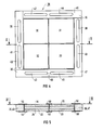
- FIG. 1 shows that the solid electrolyte high-temperature fuel cell module consists of a multiplicity of rectangular, in the exemplary embodiment square, plate-shaped elements which are stacked on one another and whose top and bottom plate - a so-called cover plate 2, 3 - in the edge area carries eight circular through holes 4, 5, 6, 7, 8, 9, 10, 11 for feeding fuel or fuel gas and air or oxygen.
- a window film shown in FIG. 6 a solid electrolyte element shown in FIGS.
- window film one in each of the following are arranged below the upper cover plate Figures 2 and 3 shown bipolar plate, another window film, another solid electrolyte element, another window film, another bipolar plate, etc. on top of each other.
- FIG. 2 shows a top view of the structure of a bipolar plate 12 constructed according to the cross-current principle.
- This is made in one piece and consists of an electrically highly conductive material whose thermal expansion coefficient in the temperature range from 0 to 1000 ° C. is as close as possible to that of the solid electrolyte plates 28. In the exemplary embodiment, this is a CrFe5Y 2 0 3 1 alloy.
- the bipolar plate 12 contains on each of its two sides two mutually parallel groove fields 14, 15, 16, 17 with parallel grooves lying directly next to one another, with the exception of one edge region covering almost the entire surface of the bipolar plate. These open at their two ends in a slit-shaped opening 18, 19, 20, 21, 22, 23, 24, 25 in the edge region of the bipolar plate 12.
- the other side of the bipolar plate is constructed in exactly the same way as the side shown with the The only difference is that the groove fields 16, 17 are rotated by 90 relative to the groove fields 14, 15 on the side shown and therefore open into the slot-shaped openings 22, 23, 24, 25 located on the side of the groove fields 14, 15.
- FIG. 4 shows a top view of a solid electrolyte element 26 of the fuel cell module 1 shown in FIG. 1. It can be seen from this top view and from the section shown in FIG. 5 that these four rectangular solid electrolyte plates 28 and on both sides of these solid electrolyte plates Contains electrodes 30, 31, 32, 33, 34, 35. The electrodes are formed on one side as a cathode and on the opposite side as an anode.
- the cathodes consist of an L " SryMn0 3 ceramic.
- the anodes consist of a nickel oxide or nickel zirconium oxide cermet.
- the solid electrolyte plates 28 consist of yttrium-stabilized zirconium oxide.
- the solid electrolyte plates 28 coated with the cathode and anode material of each solid electrolyte element 26 are placed in an electrically insulating frame 36 - in the exemplary embodiment made of MgO / Al 2 O 3 spinel - which has congruent slot-shaped openings 38, 39, 40, 41, 42 with the slot-shaped openings of the bipolar plate 12 , 43, 44, 45.
- This frame is applied to the adjoining windows on both sides with a solder 50 which melts above the operating temperature foils soldered flat.
- the geometrical structure of the solid electrolyte element is identical on both sides.
- the frame 36 is not made in one piece, but is made up of four sealing strips 46, 47, 48, 49.
- the frame is made of Mg0 / A1 2 0 3 spinel, which is sufficiently temperature-resistant and gas-tight and whose electrical conductivity is very low.
- FIG. 6 shows a plan view of a window film 52 of the fuel cell module 1 shown in FIG. 1.
- the window film consists of the same material as the bipolar plate 12. It has the same external dimensions as the bipolar plate and bears on it Edges of slot-shaped openings 54, 55, 56, 57, 58, 59, 60, 61, which are arranged with the slot-shaped openings of the bipolar plate in the same way.
- the window film 52 has four window openings 62, 63, 64, 65, which are arranged in their position so that they come to rest on the bipolar plate over the grooved areas 14, 15, 16, 17.
- the window openings can be designed without any web or, as in the other windows 62, 64, 65, with a plurality of webs 68 which run in the same way as the edges of the grooves 14, 15 of the bipolar plate 12. These webs have the function of supporting the electrodes 30, 31, 32, 33, 34, 35 of the solid electrolyte element 36 and dissipating the current.
- the fuel is fed in through the through holes 8, 9 installed on one side of the stack in the two cover plates 2, 3. It then flows into the slot-shaped openings 18, 20 of the two cover plates communicating with these through-holes and the congruently arranged slot-shaped openings 38, 40, 58, 60 in the window films 52, solid electrolyte elements 26 and bipolar plates 12 underneath and through the entire stack and through the grooves of the individual groove fields 14, 15 communicating with these slot-shaped openings in the individual bipolar plates to the slot-shaped openings 19, 21 on the opposite side of the stack and from there again through the holes 4, 5 in the two cover plates 2, 3 of the solid electrolyte -High-temperature fuel cell module 1 out again.
- the oxygen or, in the exemplary embodiment, the air flows through the holes 6, 7 let into the two cover plates 3, 4 on a side adjacent to the fuel feeds and the slot-shaped openings 22, 24 of the two bipolar cover plates communicating with them into the congruent ones below slot-shaped openings 42, 44, 54, 56 of the window foils 52, solid electrolyte elements 26 and bipolar plates 12 etc. through the entire stack and from the slot-shaped openings of the bipolar plates 12 into the grooves of the individual groove fields 16, 17 communicating with them opposite slot-shaped openings 23, 25 and from there again through the communicating through holes 10, 11 in the two cover plates 2, 3 out.
- the solid electrolyte element is oriented such that its cathode side faces the grooved fields of the adjacent bipolar plate carrying oxygen and its anode side faces the grooved fields of the other neighboring bipolar plate carrying fuel.
- the flow directions of the fuel and the oxygen are therefore arranged at right angles to one another.
- the oxygen When flowing through the groove fields, the oxygen is in direct contact with the cathodes of the individual solid electrolyte elements.
- the 0 2 molecules from the air are converted into 02 ions with electron acceptance.
- the carbon dioxide and water vapor mixture formed during the oxidation of the fuel gas is then withdrawn again together with the fuel gas.
- the fuel can be separated from the combustion products C0 2 and H 2 0 externally in a manner not shown here and fed back into the fuel supply line.
- the potential differences forming at the anode and cathode are connected in series with one another by the respective highly conductive window foils 52 and bipolar plates 12, both of which are made of a CrFe5Y 2 0 3 1 alloy.
- the sum of the potentials of the individual fuel cells 1 connected in series can be tapped at the cover plates.
- the base or cover plates, and the window films, support structures, pipelines and pantographs are also to be understood as metallic components, which should preferably be made from the alloys mentioned. These components should also have the same coefficient of expansion to avoid tension in the module or between the modules of a system.
Abstract
Description
Die Erfindung bezieht sich auf ein Material für die metallischen Komponenten von Hochtemperatur-Brennstoffzellen-Anlagen, die mit aus Yttrium stabilisiertem Zirkonoxid bestehenden keramischem Festelektrolyten versehen sind.The invention relates to a material for the metallic components of high-temperature fuel cell systems which are provided with ceramic solid electrolytes consisting of yttrium-stabilized zirconium oxide.
Hochtemperatur-Brennstoffzellen-Anlagen - auch Solid Oxide Fuel Cell (SOFC)-Anlagen genannt - eignen sich infolge der relativ hohen Betriebstemperaturen - sie liegen im Bereich von 800 bis 1100 °C - im Gegensatz zu Niedertemperatur-Brennstoffzellen-Anlagen dazu, außer Wasserstoffgas auch Kohlenwasserstoffe, wie zum Beispiel Erdgas oder flüssig speicherbares Propan, umzusetzen. Wird dem Brennstoff Kohlendioxid und Wasserdampf zugesetzt, so kann bei den hohen Temperaturen, infolge der Konvertierung des Brennstoffes, jede Rußbildung vermieden werden. Bei solchen Hochtemperatur-Brennstoffzellen-Anlagen werden temperaturbedingt feste Elektrolyte eingesetzt. Für solche Anwendungszwecke ist es bekannt, im wesentlichen aus Zirkonoxid und geringen Zusätzen etwa von Yttriumoxid, bestehende keramische Festelektrolytplatten zwischen den Elektroden einzusetzen. Bei bekannten Konstruktionen liegen die Festelektrolytplatten nebst Elektroden zu beiden Seiten unter Zwischenlage von elektrisch leitenden Fensterfolien an elektrisch gut leitenden, sogenannten bipolaren Platten an, deren gerillte Oberflächenstruktur den Zustrom von Brennstoff und Oxidator gewährleistet. Eine Vielzahl solcher Brennstoffzellen ist dann aufeinandergestapelt und damit elektrisch in Serie geschaltet und bildet so ein Brennstoffzellen-Modul oder Brennstoffzellen-Stack. Mehrere solcher Stacks können dann zu Brennstoffzellen-Anlagen zusammengebaut werden.High-temperature fuel cell systems - also called solid oxide fuel cell (SOFC) systems - are suitable due to the relatively high operating temperatures - they are in the range of 800 to 1100 ° C - in contrast to low-temperature fuel cell systems, in addition to hydrogen gas To implement hydrocarbons, such as natural gas or liquid storable propane. If carbon dioxide and water vapor are added to the fuel, any soot formation can be avoided at the high temperatures due to the conversion of the fuel. In such high-temperature fuel cell systems, temperature-dependent solid electrolytes are used. For such applications, it is known to use ceramic solid electrolyte plates consisting essentially of zirconium oxide and small additions of yttrium oxide, for example, between the electrodes. In known constructions, the solid electrolyte plates and electrodes lie on both sides with the interposition of electrically conductive window films on electrically well-conductive, so-called bipolar plates, the grooved surface structure of which ensures the inflow of fuel and oxidizer. A large number of such fuel cells are then stacked on top of one another and thus electrically connected in series and thus form a fuel cell module or fuel cell stack. Several such stacks can then be assembled into fuel cell systems.
Wegen der hohen Betriebstemperatur sind die keramischen Festelektrolytplatten starken mechanischen Spannungen ausgesetzt, wenn sich die Brennstoffzellen-Anlage bei der Inbetriebnahme aufheizt bzw. nach dem Abschalten wieder auf Zimmertemperatur abkühlt und die an der Festelektrolytplatte anliegenden anderen Bauteile, wie bipolare Platten und Fensterfolien, auch nur geringfügig unterschiedliche thermische Ausdehnungskoeffizienten besitzen. Diese Spannungen können dann zur Rißbildung in der Festelektrolytplatte führen und die Lebensdauer des Hochtemperatur-Brennstoffzellen-Moduls beträchtlich begrenzen.Because of the high operating temperature, the ceramic solid electrolyte plates are exposed to strong mechanical stresses when the fuel cell system heats up during commissioning or cools down to room temperature after switching off and the other components, such as bipolar plates and window foils, which are attached to the solid electrolyte plate, also only slightly have different coefficients of thermal expansion. These voltages can then lead to cracking in the solid electrolyte plate and considerably limit the service life of the high-temperature fuel cell module.
Durch die DE-A1-40 09 138 ist ein Festelektrolyt-Hochtemperatur-Brennstoffzellen-Modul bekannt, bei dem die an der aus Yttrium stabilisierten Zirkonoxid bestehenden Festelektrolytplatten anliegenden Fensterfolien und bipolaren Platten aus einer Chrom-Nickel-Legierung mit Nikkelgehalten von 5 bis 15 Gew. -% oder einer Eisen-Chrom-Aluminiumlegierung mit Gehalten von 5 bis 15 Gew. -% Molybdän und/oder 5 bis 15 Gew. -% Wolfram bestehen. Es ist eine Eigenart der erstgenannten Legierung, daß sie hinsichtlich ihres Ausdehnungskoeffizienten recht gut an den Ausdehnungskoeffizienten des Festelektrolyten angepaßt ist. Leider befriedigt ihre Korrosionsfestigkeit nicht ganz. Bei der zweiten Legierung ist es umgekehrt.DE-A1-40 09 138 discloses a solid electrolyte high-temperature fuel cell module in which the window foils and bipolar plates made of a chromium-nickel alloy with nickel contents of 5 to 15 wt .% or an iron-chromium-aluminum alloy with contents of 5 to 15% by weight of molybdenum and / or 5 to 15% by weight of tungsten. It is a peculiarity of the former alloy that its expansion coefficient is very well matched to the expansion coefficient of the solid electrolyte. Unfortunately, their corrosion resistance is not entirely satisfactory. The reverse is the case with the second alloy.
Der Erfindung liegt daher die Aufgabe zugrunde, einen Weg zu weisen, wie die Zyklenfestigkeit von Festelektrolyt-Hochtemperatur-Brenns toffzellen-Anlagen noch weiter gesteigert werden kann.The invention is therefore based on the object of showing a way in which the cycle stability of solid electrolyte high-temperature fuel cell systems can be increased still further.
Diese Aufgabe wird durch die Merkmale des Anspruchs 1 gelöst. Weitere vorteilhafte Ausgestaltungen der Erfindung sind den Ansprüchen 2 bis 4 zu entnehmen.This object is solved by the features of
Dadurch, daß für die metallischen Komponenten von Hochtemperatur-Brennstoffzellen-Anlagen, deren Festelektrolytplatten aus Yttrium stabilsiertem Zirkonoxid bestehen, erfindungsgemäß ein Material verwendet ist, das aus einer Chromlegierung mit 3 bis 10 Atomprozent Eisen sowie 0,5 bis 5 Atomprozent Seltenes Erdmetall und/oder Seltenes Erdmetalloxid besteht und dessen thermischer Ausdehnungskoeffizient bei einer Temperatur von 200 ° C 8,5 x 10⁻⁶ bis 10,5 x 10⁻⁶ je Grad Kelvin beträgt, mit der Temperatur ansteigt und bei 900 ° C einen Wert im Bereich von 14 x 10-6 bis 15 x 10-6 erreicht, ist eine wesentliche Voraussetzung geschaffen worden, um die beim Abkühlen sowie beim Wiederaufheizen auftretenden Dehnungsdifferenzen bei den in Frage kommenden Abmessungen so zu minimieren, daß der im wesentlichen aus Zirkonoxid bestehende keramische Festelektrolyt die damit verbundenen Spannungen ohne Rißbildung elastisch auffangen kann. Hierbei ist berücksichtigt, daß wegen der hohen Sprödigkeit und geringen Zugfestigkeit der Festelektrolytplatten nur verhältnismäßig geringe Zugspannungen aufgenommen werden können. Darüber hinaus ist hierfür mit einer Chromlegierung ein Material verwendet worden, welches sich bei den in Hochtemperatur-Brennstoffzellen herrschenden physikalischen und chemischen Bedingungen durch gutes Korrosions-und Diffusionsverhalten auszeichnet.Characterized in that for the metallic components of high-temperature fuel cell systems, whose solid electrolyte plates consist of yttrium-stabilized zirconium oxide, a material is used according to the invention which is made of a chromium alloy with 3 to 10 atomic percent iron and 0.5 to 5 atomic percent rare earth metal and / or Rare earth metal oxide exists and its thermal expansion coefficient at a temperature of 200 ° C is 8.5 x 10- 6 to 10.5 x 10- 6 per degree Kelvin, increases with temperature and at 900 ° C a value in the range of 14 x 10- 6 to 15 x 10- 6 reached, an essential requirement has been created in order to minimize the expansion differences occurring during cooling and reheating in the dimensions in question so that the ceramic solid electrolyte consisting essentially of zirconium oxide and the associated voltages can catch elastically without cracking. This takes into account the fact that, due to the high brittleness and low tensile strength of the solid electrolyte plates, only relatively low tensile stresses can be absorbed. In addition, a material with a chrome alloy has been used which is characterized by good corrosion and diffusion behavior under the physical and chemical conditions prevailing in high-temperature fuel cells.
In zweckmäßiger Weiterbildung der Erfindung kann der mittlere thermische Ausdehnungskoeffizient des Materials im gesamten Temperaturbereich von 0 bis 1000 ° C um weniger als 10 % vom Ausdehnungskoeffizienten des Yttrium stabilisierten Zirkonoxids abweichen. Dies hat zur Folge, daß die Yttrium stabilisierten Zirkonoxidplatten, die warm mit den metallischen Fensterfolien verlötet werden, beim Aufheizen oder Abkühlen nur kurzfristig Temperaturzonen mit geringen Spannungen durchlaufen.In an expedient development of the invention, the average thermal expansion coefficient of the material in the entire temperature range from 0 to 1000 ° C. can deviate by less than 10% from the expansion coefficient of the yttrium-stabilized zirconium oxide. The result of this is that the yttrium-stabilized zirconium oxide plates, which are warmly soldered to the metallic window foils, only pass through temperature zones with low voltages for a short time when heating or cooling.
In besonders vorteilhafter Weiterbildung kann das Material eine CrFe5Y2031-Legierung sein. Der mittlere Ausdehnungskoeffizient einer solchen Legierung stimmt im Bereich von 0 ° C bis 1000 ° C bis auf 5 % mit dem Ausdehnungskoeffizienten einer Yttrium stabilisierten zirkonoxidhaltigen Festelektrolytplatte überein.In a particularly advantageous development, the material can be a CrFe5Y 2 0 3 1 alloy. The The average coefficient of expansion of such an alloy corresponds in the range from 0 ° C. to 1000 ° C. to 5% with the coefficient of expansion of a yttrium-stabilized zirconium oxide-containing solid electrolyte plate.
Weitere Einzelheiten der Erfindung werden anhand eines in den Figuren dargestellten Ausführungsbeispiels erläutert. Es zeigen:
Figur 1 eine schaubildliche Ansicht eines Festelektrolyt-Hochtemperatur-Brennstoffzellen-Moduls,- Figur 2 eine Aufsicht auf eine bipolare Platte des Brennstoffzellen-Moduls der
Figur 1, Figur 3 einen Schnitt längs der Linie III-III der Figur 2,- Figur 4 eine Aufsicht auf ein Festelektrolyt-Element des Brennstoffzellen-Moduls,
Figur 5 einen Querschnitt durch die Linie V-V der Figur 4 undFigur 6 eine Aufsicht auf eine Fensterfolie des Brennstoffzellen-Moduls derFigur 1.
- FIG. 1 shows a perspective view of a solid electrolyte high-temperature fuel cell module,
- FIG. 2 shows a top view of a bipolar plate of the fuel cell module of FIG. 1,
- 3 shows a section along the line III-III of FIG. 2,
- FIG. 4 shows a top view of a solid electrolyte element of the fuel cell module,
- 5 shows a cross section through the line VV of Figure 4 and
- 6 shows a plan view of a window film of the fuel cell module of FIG. 1.
Die schaubildliche Ansicht der Figur 1 zeigt, daß das Festelektrolyt-Hochtemperatur-Brennstoffzellen-Modul aus einer Vielzahl von rechteckigen, im Ausführungsbeispiel quadratischen, plattenförmigen Elementen besteht, die aufeinandergestapelt sind und deren oberste und unterste Platte - eine sogenannte Deckplatte 2, 3 - im Randbereich acht kreisrunde Durchgangslöcher 4, 5, 6, 7, 8, 9, 10, 11 zur Einspeisung von Brennstoff bzw. Brenngas und Luft bzw. Sauerstoff trägt. In dem in der Figur 1 dargestellten Festelektrolyt-Hochtemperatur-Brennstoffzellen-Modul 1 liegen unter der oberen Deckplatte der Reihenfolge nach eine in der Figur 6 dargestellte Fensterfolie, ein in den Figuren 4 und 5 dargestelltes Festelektrolyt-Element, eine weitere Fensterfolie, eine in den Figuren 2 und 3 dargestellte bipolare Platte, eine weitere Fensterfolie, ein weiteres Festelektrolyt-Element, eine weitere Fensterfolie, eine weitere bipolare Platte usw. aufeinander. Dabei bilden jeweils ein zwischen zwei benachbarten bipolaren Platten liegendes Festelektrolyt-Element einschließlich der beidseitig am Festelektrolyt-Element unmittelbar anliegenden Fensterfolien und der an den Fensterfolien anliegenden Seiten jeder der beiden bipolaren Platten zusammen eine Festelektrolyt-Hochtemperatur-Brennstoffzelle.The diagrammatic view of FIG. 1 shows that the solid electrolyte high-temperature fuel cell module consists of a multiplicity of rectangular, in the exemplary embodiment square, plate-shaped elements which are stacked on one another and whose top and bottom plate - a so-called cover plate 2, 3 - in the edge area carries eight circular through
Die Figur 2 zeigt in einer Aufsicht den Aufbau eine nach dem Kreuzstromprinzip aufgebaute bipolare Platte 12. Diese ist einteilig ausgeführt und besteht aus einem elektrisch gut leitendem Werkstoff, dessen thermischer Ausdehnungskoeffizient im Temperaturbereich von 0 bis 1000 °C möglichst nahe dem der Festelektrolytplatten 28 liegt. Im Ausführungsbeispiel ist dies eine CrFe5Y2031-Legierung. Die bipolare Platte 12 enthält auf jeder ihrer beiden Seiten zwei zueinander parallele, mit Ausnahme eines Randbereichs nahezu die gesamte Fläche der bipolaren Platte überdeckende Rillenfelder 14, 15, 16, 17 mit unmittelbar aneinanderliegenden parallelen Rillen. Diese münden an ihren beiden Enden in je einen schlitzförmigen Durchbruch 18, 19, 20, 21, 22, 23, 24, 25 im Randbereich der bipolaren Platte 12. Auch die andere Seite der bipolaren Platte ist genauso aufgebaut wie die ab gebildete Seite mit dem einzigen Unterschied, daß dort die Rillenfelder 16, 17 um 90 gegenüber den Rillenfeldern 14, 15 auf der abgebildeten Seite verdreht sind und daher in den seitlich der Rillenfelder 14, 15 befindlichen schlitzförmigen Durchbrüchen 22, 23, 24, 25 münden. Dies wird auch aus der Schnittdarstellung in der Figur 3 deutlich, bei der auf der Oberseite eine Rille in Längsrichtung geschnitten ist und auf der Unterseite die Rillen der beiden Rillenfelder 16, 17 in Querrichtung geschnitten sind.FIG. 2 shows a top view of the structure of a
Nur die beiden als obere und untere Deckplatte des Festelektrolyt-Hochtemperatur-Brennstoffzellen -Moduls 1 dienenden bipolaren Platten 2, 3 tragen auf ihren jeweiligen Außenseiten keine Rillen. Auch sind bei ihnen die schlitzförmigen Durchbrüche nicht durchgefräst, sondern nur auf der Seite mit den Rillen bis zur Tiefe der Rillen eingesenkt. Im Bereich dieser schlitzförmigen Einsenkung ist im Ausführungsbeispiel nur je ein Durchgangsloch 4, 5, 6, 7, 8, 9, 10, 11 vorgesehen, über das von außen die jeweiligen Leitungen (nicht dargestellt) für den Brennstoff bzw. den Sauerstoffträger anschließbar sind.Only the two
Die Figur 4 zeigt eine Aufsicht auf ein Festelektrolyt-Element 26 des in der Figur 1 gezeigten Brennstoffzellen-Moduls 1. Man erkennt aus dieser Aufsicht und aus dem in der Figur 5 gezeigten Schnitt, daß diese vier rechteckigen Festelektrolytplatten 28 sowie beidseitig auf diesen Festelektrolytplatten aufgebrachte Elektroden 30, 31, 32, 33, 34, 35 enthält. Dabei sind die Elektroden auf der einen Seite als Kathode und auf der gegenüberliegenden Seite als Anode ausgebildet. Die Kathoden bestehen im Ausführungsbeispiel aus einer L"SryMn03-Keramik. Die Anoden bestehen im Ausführungsbeispiel aus einer Nickeloxid- bzw. Nickelzirkonoxid-Cermet. Im Ausführungsbeispiel bestehen die Festelektrolytplatten 28 aus Yttrium stabilisiertem Zirkonoxid. Die mit dem Kathoden-und Anodenmaterial beschichteten Festelektrolytplatten 28 eines jeden Festelektrolyt-Elements 26 sind in einem elektrisch isolierenden Rahmen 36 - im Ausführungsbeispiel aus MgO/AI203-Spinell - eingelegt, welcher mit den schlitzförmigen Durchbrüchen der bipolaren Platte 12 deckungsgleich angeordnete schlitzförmige Durchbrüche 38, 39, 40, 41, 42, 43, 44, 45 trägt. Dieser Rahmen wird beidseitig mit einem über der Betriebstemperatur schmelzenden Lot 50 auf die anliegenden Fensterfolien flächig aufgelötet. Sieht man einmal von dem unterschiedlichen Kathoden- und Anodenmaterial ab, so ist der geometrische Aufbau des Festelektrolyt-Elements auf seinen beiden Seiten identisch. Im Ausführungsbeispiel ist der Rahmen 36 nicht einstückig, sondern aus vier Dichtleisten 46, 47, 48, 49 aufgebaut. Der Rahmen besteht aus Mg0/A1203-Spinell, das hinreichend temperaturfest und gasdicht ist und dessen elektrische Leitfähigkeit sehr gering ist.FIG. 4 shows a top view of a
Die Figur 6 zeigt eine Aufsicht auf eine Fensterfolie 52 des in der Figur 1 gezeigten Brennstoffzellen-Moduls 1. Die Fensterfolie besteht im Ausführungsbeispiel aus dem gleichen Material wie die bipolare Platte 12. Sie hat die gleichen äußeren Abmessungen wie die bipolare Platte und trägt an ihren Rändern schlitzförmige Durchbrüche 54, 55, 56, 57, 58, 59, 60, 61, die mit den schlitzförmigen Durchbrüchen der bipolaren Platte dekkungsgleich angeordnet sind. Außerdem hat die Fensterfolie 52 vier Fensteröffnungen 62, 63, 64, 65, die in ihrer Lage so angeordnet sind, daß sie bei Auflage auf der bipolaren Platte über den Rillenfeldern 14, 15, 16, 17 zum Liegen kommen. Die Fensterdurchbrüche können wie beim linken unteren Fenster 63 ohne jeden Steg oder wie bei den anderen Fenstern 62, 64, 65 mit mehreren dekkungsgleich zu den Rändern der Rillen 14, 15 der bipolaren Platte 12 verlaufenden Stege 68 ausgeführt sein. Diese Stege haben die Funktion, die Elektroden 30, 31, 32, 33, 34, 35 des Festelektrolyt-Elements 36 abzustützen und den Strom abzuführen.FIG. 6 shows a plan view of a
Beim Betrieb des Festelektrolyt-Hochtemperatur-Brennstoff-zellen-Moduls 1 wird der Brennstoff durch die an der einen Seite des Stapels in den beiden Deckplatten 2, 3 eingebauten Durchgangslöchern 8, 9 eingespeist. Er strömt dann in die mit diesen Durchgangslöchern kommunizierenden schlitzförmigen Durchbrüche 18, 20 der beiden Deckplatten und die deckungsgleich angeordneten schlitzförmigen Durchbrüche 38, 40, 58, 60 in den darunterliegenden Fensterfolien 52, Festelektrolyt-Elementen 26 und bipolaren Platten 12 durch den ganzen Stapel hindurch und durch die mit diesen schlitzförmigen Durchbrüchen in den einzelnen bipolaren Platten kommunizierenden Rillen der einzelnen Rillenfelder 14, 15 zu den schlitzförmigen Durchbrüchen 19, 21 der gegenüberliegenden Seite des Stapels und von dort wieder durch die Bohrungen 4, 5 in den beiden Deckplatten 2, 3 des Festelektrolyt-Hochtemperatur-Brennstoffzellen-Moduls 1 wieder heraus. In gleicher Weise strömt der Sauerstoff bzw. im Ausführungsbeispiel die Luft durch die auf einer den Brennstoffzuführungen benachbarten Seite in den beiden Deckplatten 3, 4 eingelassenen Bohrungen 6, 7 und die mit diesen kommunizierenden schlitzförmigen Durchbrüchen 22, 24 der beiden bipolaren Deckplatten in die deckungsgleich darunterliegenden schlitzförmigen Durchbrüche 42, 44, 54, 56 der Fensterfolien 52, Festelektrolyt-Elementen 26 und bipolaren Platten 12 usw. durch den ganzen Stapel hindurch und von den schlitzförmigen Durchbrüchen der bipolaren Platten 12 in die dazu kommunizierenden Rillen der einzelnen Rillenfelder 16, 17 zu den gegenüberliegenden schlitzförmigen Durchbrüchen 23, 25 und von dort aus wiederum durch die mit diesen kommunizierenden Durchgangslöcher 10, 11 in den beiden Deckplatten 2, 3 heraus. Dabei ist das Festelektrolyt-Element so orientiert, daß seine Kathodenseite den Sauerstoff führenden Rillenfeldern der benachbarten bipolaren Platte und seine Anodenseite dem Brennstoff führenden Rillenfeldern der anderen, benachbarten bipolaren Platte zugewandt ist. Die Strömungsrichtungen des Brennstoffs und des Sauerstoffs sind daher rechtwinklig zueinander angeordnet. Man spricht hier vom Kreuzstromprinzip.When the solid electrolyte high-temperature
Beim Durchströmen der Rillenfelder befindet sich der Sauerstoff in direktem Kontakt mit den Kathoden der einzelnen Festelektrolyt-Elemente. An der Phasengrenze Kathode-Festelektrolyt werden die 02-Moleküle aus der Luft unter Elektronenaufnahme in 02 -lonen umgewandelt. Als 02 -lonen können sie über Sauerstoffleerstellen durch den Zirkonoxid-Festelektrolyten wandern. Dabei gelangen sie schließlich zur Anode, wo sie an der Phasengrenze Anode-Festelektrolyt unter Abgabe von Elektroden mit dem Brenngas zu Kohlendioxid und Wasserdampf reagieren. Das sich bei der Oxidation des Brenngases bildende Kohlendioxid- und Wasserdampfgemisch wird dann zusammen mit dem Brenngas wieder abgezogen. Dabei kann der Brennstoff extern in einer hier nicht weiter dargestellten Weise von den Verbrennungsprodukten C02 und H20 getrennt und wieder in die Brennstoffzuführungsleitung eingespeist werden. Die an der Anode und Kathode sich bildenden Potentialunterschiede sind durch die jeweiligen gut leitenden Fensterfolien 52 und bipolaren Platten 12, die beide aus einer CrFe5Y2031-Legierung bestehen, untereinander in Serie geschaltet. Die Summe der in Serie geschalteten Potentiale der einzelnen Brennstoffzellen 1 können an den Deckplatten abgegriffen werden.When flowing through the groove fields, the oxygen is in direct contact with the cathodes of the individual solid electrolyte elements. At the phase boundary between the cathode and the solid electrolyte, the 0 2 molecules from the air are converted into 02 ions with electron acceptance. As 0 2 - ions they can migrate through oxygen vacancies through the zirconium oxide solid electrolyte. They finally reach the anode, where they react with the fuel gas to form carbon dioxide and water vapor at the anode solid electrolyte phase boundary. The carbon dioxide and water vapor mixture formed during the oxidation of the fuel gas is then withdrawn again together with the fuel gas. The fuel can be separated from the combustion products C0 2 and H 2 0 externally in a manner not shown here and fed back into the fuel supply line. The potential differences forming at the anode and cathode are connected in series with one another by the respective highly conductive window foils 52 and
Dadurch, daß sowohl für die Fensterfolien als auch für die bipolaren Platten eine CrFe5Y2031-Legierung verwendet ist, haben diese unmittelbar an den einzelnen Festelektrolyt-Elementen anliegenden plattenförmigen Bauteile einen Ausdehnungskoeffizienten, der über den gesamten Temperaturbereich von 0 °C bis 1000 °C mit den Ausdehnungskoeffizienten des aus Yttrium stabilisierten Zirkonoxid bestehenden Festelektrolyten weitgehend übereinstimmt. Die Differenz dieser beiden Ausdehnungskoeffizienten von Festelektrolytplatten einerseits und Fensterfolien und bipolaren Platten andererseits ist so gering, daß bei den gegebenen Abmessungen des Festelektrolyten von 5 cm Dehnungsunterschiede erzeugt werden, die noch im Bereich der Elastizität des Keramikmaterials des Festelektrolyt-Elements liegen. Dadurch wird vermieden, daß auch bei häufigem Ein-und Ausschalten des Hochtemperatur-Brennstoff-Elements mit den dabei verbundenen starken Temperaturänderungen eine Rißbildung im Festelektrolyten entstehen kann. Dadurch, daß der mittlere Ausdehnungskoeffizient der Legierung im Temperaturbereich von 0 °C bis 1000 °C wenig über dem Ausdehnungskoeffizienten von Yttrium stabilisiertem Zirkonoxid liegt, wird, ausgehend von der Löttemperatur, mit der die Fensterfolie auf das Festelektrolyt-Element aufgelötet wird, letzteres bei niedrigeren Temperaturen eher gestaucht denn gedehnt. Dies kommt der geringen Zugfestigkeit des Festelektrolyten entgegen.Because a CrFe5Y 2 0 3 1 alloy is used both for the window films and for the bipolar plates, these plate-shaped components lying directly on the individual solid electrolyte elements have an expansion coefficient that extends over the entire temperature range from 0 ° C to 1000 ° C largely corresponds to the expansion coefficient of the solid electrolyte consisting of yttrium-stabilized zirconium oxide. The difference of this both expansion coefficients of solid electrolyte plates on the one hand and window foils and bipolar plates on the other hand are so small that with the given dimensions of the solid electrolyte of 5 cm expansion differences are generated which are still in the range of the elasticity of the ceramic material of the solid electrolyte element. This prevents the formation of cracks in the solid electrolyte even with frequent switching on and off of the high-temperature fuel element with the associated strong temperature changes. The fact that the average coefficient of expansion of the alloy in the temperature range from 0 ° C to 1000 ° C is slightly above the coefficient of expansion of yttrium-stabilized zirconium oxide, based on the soldering temperature with which the window film is soldered to the solid electrolyte element, the latter at lower Temperatures compressed rather than stretched. This complies with the low tensile strength of the solid electrolyte.
Als metallische Komponenten, die vorzugsweise aus den genannten Legierungen gefertigt werden sollten, sind außer den bipolaren Platten, den Grund- oder Deckplatten, und den Fensterfolien auch Stützkonstruktionen, Rohrleitungen und Stromabnehmer zu verstehen. Auch diese Bauelemente sollten den gleichen Ausdehnungskoeffizienten aufweisen, um Verspannungen im Modul oder zwischen den Modulen einer Anlage zu vermeiden.In addition to the bipolar plates, the base or cover plates, and the window films, support structures, pipelines and pantographs are also to be understood as metallic components, which should preferably be made from the alloys mentioned. These components should also have the same coefficient of expansion to avoid tension in the module or between the modules of a system.
Claims (10)
Geänderte Patentansprüche Regel 86 (2) EPÜ4. Material according to any one of claims 1 to 3, characterized in that the rare earth metal is yttrium.
Amended claims Rule 86 (2) EPC
Priority Applications (8)
| Application Number | Priority Date | Filing Date | Title |
|---|---|---|---|
| ES92112123T ES2087357T3 (en) | 1992-07-16 | 1992-07-16 | MATERIAL FOR METALLIC COMPONENTS OF FUEL CELL FACILITIES AT HIGH TEMPERATURE. |
| DE59206124T DE59206124D1 (en) | 1992-07-16 | 1992-07-16 | Material for the metallic components of high-temperature fuel cell systems |
| AT92112123T ATE137361T1 (en) | 1992-07-16 | 1992-07-16 | MATERIAL FOR THE METALLIC COMPONENTS OF HIGH TEMPERATURE FUEL CELL SYSTEMS |
| DK92112123.2T DK0578855T3 (en) | 1992-07-16 | 1992-07-16 | Material for the metallic components of High Temperature Fuel Cell Systems |
| EP92112123A EP0578855B1 (en) | 1992-07-16 | 1992-07-16 | Material for the metallic components of high-temperature fuel cell stacks |
| JP19539593A JP3432547B2 (en) | 1992-07-16 | 1993-07-12 | Materials for metal components of high-temperature fuel cell equipment |
| US08/093,049 US5407758A (en) | 1992-07-16 | 1993-07-16 | Material for the metal components of high-temperature fuel cell systems |
| GR960401469T GR3020103T3 (en) | 1992-07-16 | 1996-05-30 | Material for the metallic components of high-temperature fuel cell stacks |
Applications Claiming Priority (1)
| Application Number | Priority Date | Filing Date | Title |
|---|---|---|---|
| EP92112123A EP0578855B1 (en) | 1992-07-16 | 1992-07-16 | Material for the metallic components of high-temperature fuel cell stacks |
Publications (2)
| Publication Number | Publication Date |
|---|---|
| EP0578855A1 true EP0578855A1 (en) | 1994-01-19 |
| EP0578855B1 EP0578855B1 (en) | 1996-04-24 |
Family
ID=8209813
Family Applications (1)
| Application Number | Title | Priority Date | Filing Date |
|---|---|---|---|
| EP92112123A Expired - Lifetime EP0578855B1 (en) | 1992-07-16 | 1992-07-16 | Material for the metallic components of high-temperature fuel cell stacks |
Country Status (8)
| Country | Link |
|---|---|
| US (1) | US5407758A (en) |
| EP (1) | EP0578855B1 (en) |
| JP (1) | JP3432547B2 (en) |
| AT (1) | ATE137361T1 (en) |
| DE (1) | DE59206124D1 (en) |
| DK (1) | DK0578855T3 (en) |
| ES (1) | ES2087357T3 (en) |
| GR (1) | GR3020103T3 (en) |
Cited By (12)
| Publication number | Priority date | Publication date | Assignee | Title |
|---|---|---|---|---|
| WO1996017394A1 (en) * | 1994-12-01 | 1996-06-06 | Siemens Aktiengesellschaft | Fuel cell with bipolar flanges coated with ceramic material and its production |
| DE19546614A1 (en) * | 1995-12-13 | 1997-06-19 | Forschungszentrum Juelich Gmbh | Oxidation-resistant, chromium oxide-forming alloy |
| DE19605086C1 (en) * | 1996-02-12 | 1997-06-26 | Siemens Ag | High-temperature fuel cell and from such existing high-temperature fuel cell stacks |
| DE19643157C1 (en) * | 1996-10-18 | 1998-01-15 | Siemens Ag | Production of chromium material used for part of fuel cell |
| DE19643156C1 (en) * | 1996-10-18 | 1998-02-19 | Siemens Ag | High purity chromium alloy production |
| US5942348A (en) * | 1994-12-01 | 1999-08-24 | Siemens Aktiengesellschaft | Fuel cell with ceramic-coated bipolar plates and a process for producing the fuel cell |
| US7390456B2 (en) | 2001-01-15 | 2008-06-24 | Plansee Aktiengesellschaft | Powder-metallurgic method for producing highly dense shaped parts |
| EP2230707A1 (en) | 2009-03-12 | 2010-09-22 | Plansee Se | Interconnector of a solid electrolyte high temperature fuel cell |
| WO2015027257A2 (en) | 2013-09-02 | 2015-03-05 | Plansee Se | Powdered metal component |
| CN104419857A (en) * | 2013-08-20 | 2015-03-18 | 东睦新材料集团股份有限公司 | Chromium-based alloy and preparation method thereof |
| CN104419856A (en) * | 2013-08-20 | 2015-03-18 | 东睦新材料集团股份有限公司 | Chromium-based alloy and manufacturing method thereof |
| US10724074B2 (en) | 2012-09-25 | 2020-07-28 | Qiagen Gmbh | Stabilisation of biological samples |
Families Citing this family (15)
| Publication number | Priority date | Publication date | Assignee | Title |
|---|---|---|---|---|
| US5804326A (en) * | 1996-12-20 | 1998-09-08 | Ballard Power Systems Inc. | Integrated reactant and coolant fluid flow field layer for an electrochemical fuel cell |
| AUPP042597A0 (en) | 1997-11-17 | 1997-12-11 | Ceramic Fuel Cells Limited | A heat resistant steel |
| US6030718A (en) | 1997-11-20 | 2000-02-29 | Avista Corporation | Proton exchange membrane fuel cell power system |
| US6096449A (en) | 1997-11-20 | 2000-08-01 | Avista Labs | Fuel cell and method for controlling same |
| KR100283207B1 (en) * | 1998-08-03 | 2001-05-02 | 손재익 | Metal Connecting Material for Solid Oxide Fuel Cell and Manufacturing Method Thereof |
| US7326480B2 (en) * | 2000-05-17 | 2008-02-05 | Relion, Inc. | Fuel cell power system and method of controlling a fuel cell power system |
| US6468682B1 (en) | 2000-05-17 | 2002-10-22 | Avista Laboratories, Inc. | Ion exchange membrane fuel cell |
| US20060166053A1 (en) * | 2001-11-21 | 2006-07-27 | Badding Michael E | Solid oxide fuel cell assembly with replaceable stack and packet modules |
| US20040001991A1 (en) * | 2002-07-01 | 2004-01-01 | Kinkelaar Mark R. | Capillarity structures for water and/or fuel management in fuel cells |
| CA2452657C (en) * | 2003-02-18 | 2009-03-03 | Sulzer Markets And Technology Ag | A power source with solid oxide fuel cells |
| US20080014492A1 (en) * | 2006-07-14 | 2008-01-17 | Jens Ulrick Nielsen | Compression assembly, solid oxide fuel cell stack, a process for compression of the solid oxide fuel cell stack and its use |
| DK1879251T3 (en) * | 2006-07-14 | 2012-09-17 | Topsoee Fuel Cell As | Compression Device, Fast Oxide Fuel Cell Stack, Procedure For Compressing the Fast Oxide Fuel Cell Stack and Its Use |
| US20090068055A1 (en) * | 2007-09-07 | 2009-03-12 | Bloom Energy Corporation | Processing of powders of a refractory metal based alloy for high densification |
| CN104419858A (en) * | 2013-08-20 | 2015-03-18 | 东睦新材料集团股份有限公司 | Chromium-based alloy and preparation method thereof |
| AT513501B1 (en) | 2013-09-02 | 2014-05-15 | Abatec Group Ag | IR emitter with double glazing |
Citations (5)
| Publication number | Priority date | Publication date | Assignee | Title |
|---|---|---|---|---|
| US3516865A (en) * | 1967-08-30 | 1970-06-23 | Gen Electric | Electrochemical cell including iron-chromium alloy conductor connected to cathode |
| EP0338823A1 (en) * | 1988-04-21 | 1989-10-25 | Toa Nenryo Kogyo Kabushiki Kaisha | Solid electrolyte type fuel cells |
| EP0411374A1 (en) * | 1989-07-31 | 1991-02-06 | Asea Brown Boveri Ag | Current conduction element for high temperature ceramic fuel cells |
| EP0425939A1 (en) * | 1989-10-26 | 1991-05-08 | Siemens Aktiengesellschaft | Solid electrolyte high-temperature fuelcell module |
| EP0510495A1 (en) * | 1991-04-26 | 1992-10-28 | Kubota Corporation | Oxide-dispersion-strengthened heat-resistant sintered alloy |
Family Cites Families (2)
| Publication number | Priority date | Publication date | Assignee | Title |
|---|---|---|---|---|
| US3017265A (en) * | 1959-09-25 | 1962-01-16 | Gen Electric | Oxidation resistant iron-chromium alloy |
| JPH0832942B2 (en) * | 1989-03-30 | 1996-03-29 | 株式会社クボタ | Composite sintered alloy, heat resistant member and steel support member in heating furnace |
-
1992
- 1992-07-16 AT AT92112123T patent/ATE137361T1/en active
- 1992-07-16 EP EP92112123A patent/EP0578855B1/en not_active Expired - Lifetime
- 1992-07-16 ES ES92112123T patent/ES2087357T3/en not_active Expired - Lifetime
- 1992-07-16 DK DK92112123.2T patent/DK0578855T3/en active
- 1992-07-16 DE DE59206124T patent/DE59206124D1/en not_active Expired - Lifetime
-
1993
- 1993-07-12 JP JP19539593A patent/JP3432547B2/en not_active Expired - Lifetime
- 1993-07-16 US US08/093,049 patent/US5407758A/en not_active Expired - Lifetime
-
1996
- 1996-05-30 GR GR960401469T patent/GR3020103T3/en unknown
Patent Citations (6)
| Publication number | Priority date | Publication date | Assignee | Title |
|---|---|---|---|---|
| US3516865A (en) * | 1967-08-30 | 1970-06-23 | Gen Electric | Electrochemical cell including iron-chromium alloy conductor connected to cathode |
| EP0338823A1 (en) * | 1988-04-21 | 1989-10-25 | Toa Nenryo Kogyo Kabushiki Kaisha | Solid electrolyte type fuel cells |
| EP0411374A1 (en) * | 1989-07-31 | 1991-02-06 | Asea Brown Boveri Ag | Current conduction element for high temperature ceramic fuel cells |
| EP0425939A1 (en) * | 1989-10-26 | 1991-05-08 | Siemens Aktiengesellschaft | Solid electrolyte high-temperature fuelcell module |
| DE4009138A1 (en) | 1989-10-26 | 1991-09-26 | Siemens Ag | FIXED ELECTROLYTE HIGH TEMPERATURE FUEL CELL MODULE |
| EP0510495A1 (en) * | 1991-04-26 | 1992-10-28 | Kubota Corporation | Oxide-dispersion-strengthened heat-resistant sintered alloy |
Non-Patent Citations (2)
| Title |
|---|
| BERICHTE DER BUNSEN-GESELLSCHAFT FUR PHYSIKALISCHE CHEMIE Bd. 94, Nr. 9, 1990, WEINHEIM DE Seiten 978 - 981 E. IVERS-TIFFÉE ET AL 'Ceramic and Metallic Components for a Planar SOFC' * |
| PATENT ABSTRACTS OF JAPAN vol. 15, no. 007 (C-0794)9. Januar 1991 & JP-A-02 258 946 ( KUBOTA LTD ) 19. Oktober 1990 * |
Cited By (14)
| Publication number | Priority date | Publication date | Assignee | Title |
|---|---|---|---|---|
| WO1996017394A1 (en) * | 1994-12-01 | 1996-06-06 | Siemens Aktiengesellschaft | Fuel cell with bipolar flanges coated with ceramic material and its production |
| US5942348A (en) * | 1994-12-01 | 1999-08-24 | Siemens Aktiengesellschaft | Fuel cell with ceramic-coated bipolar plates and a process for producing the fuel cell |
| DE19546614C2 (en) * | 1995-12-13 | 1998-12-17 | Forschungszentrum Juelich Gmbh | Oxidation-resistant, chromium oxide-forming alloy |
| DE19546614A1 (en) * | 1995-12-13 | 1997-06-19 | Forschungszentrum Juelich Gmbh | Oxidation-resistant, chromium oxide-forming alloy |
| DE19605086C1 (en) * | 1996-02-12 | 1997-06-26 | Siemens Ag | High-temperature fuel cell and from such existing high-temperature fuel cell stacks |
| DE19643157C1 (en) * | 1996-10-18 | 1998-01-15 | Siemens Ag | Production of chromium material used for part of fuel cell |
| DE19643156C1 (en) * | 1996-10-18 | 1998-02-19 | Siemens Ag | High purity chromium alloy production |
| US7390456B2 (en) | 2001-01-15 | 2008-06-24 | Plansee Aktiengesellschaft | Powder-metallurgic method for producing highly dense shaped parts |
| EP2230707A1 (en) | 2009-03-12 | 2010-09-22 | Plansee Se | Interconnector of a solid electrolyte high temperature fuel cell |
| US9029044B2 (en) | 2009-03-12 | 2015-05-12 | Plansee Se | Interconnector for a high-temperature solid electrolyte fuel cell, method of producing a fuel cell, and high-temperature solid electrolyte fuel cell |
| US10724074B2 (en) | 2012-09-25 | 2020-07-28 | Qiagen Gmbh | Stabilisation of biological samples |
| CN104419857A (en) * | 2013-08-20 | 2015-03-18 | 东睦新材料集团股份有限公司 | Chromium-based alloy and preparation method thereof |
| CN104419856A (en) * | 2013-08-20 | 2015-03-18 | 东睦新材料集团股份有限公司 | Chromium-based alloy and manufacturing method thereof |
| WO2015027257A2 (en) | 2013-09-02 | 2015-03-05 | Plansee Se | Powdered metal component |
Also Published As
| Publication number | Publication date |
|---|---|
| ES2087357T3 (en) | 1996-07-16 |
| JPH06188004A (en) | 1994-07-08 |
| DE59206124D1 (en) | 1996-05-30 |
| ATE137361T1 (en) | 1996-05-15 |
| GR3020103T3 (en) | 1996-08-31 |
| DK0578855T3 (en) | 1996-09-02 |
| US5407758A (en) | 1995-04-18 |
| JP3432547B2 (en) | 2003-08-04 |
| EP0578855B1 (en) | 1996-04-24 |
Similar Documents
| Publication | Publication Date | Title |
|---|---|---|
| EP0578855B1 (en) | Material for the metallic components of high-temperature fuel cell stacks | |
| EP0425939B1 (en) | Solid electrolyte high-temperature fuelcell module | |
| DE69838679T2 (en) | ELECTRICAL CONDUCTIVITY IN A FUEL CELL ARRANGEMENT | |
| DE60019238T2 (en) | FLAT SOLID OXIDE FUEL CELL STACK WITH METAL FOIL INTERCONNECTORS | |
| EP0378812A1 (en) | Arrangement of fuel cells based on a solid electrolyte operating at a high temperature, consisting of zirconium oxide, to obtain maximum possible power | |
| CH679620A5 (en) | ||
| EP0966771B1 (en) | Material for electric contact layers between a high-temperature fuel cell electrode and an interconnector | |
| DE4016157A1 (en) | High temp. fuel cell stack - with cells series-connected by separator plates and elastic current collectors | |
| EP0840388A1 (en) | Battery of planar high-temperature fuel cells | |
| EP0424732A1 (en) | Current conduction element for stacked hightemperature fuel cells and method of manufacture | |
| DE4237602A1 (en) | High temperature fuel cell stack and process for its manufacture | |
| EP0432381A1 (en) | Arrangement of elements for the conduction of current between ceramic high temperature fuel cells | |
| DE19841919C2 (en) | Method for producing a fuel cell module | |
| DE10033898B4 (en) | High temperature fuel cell and fuel cell stack | |
| DE19650704C2 (en) | Connection element for fuel cells | |
| DE3935722A1 (en) | High-temp. fuel cell module contg. solid electrolyte - allows gas distribution via channels in frames around bipolar coated zirconia plates with separate sealing surfaces | |
| EP1027743A2 (en) | Method for the production of high temperature fuel cells | |
| EP0424691A1 (en) | Arrangement of elements for the conduction of current between ceramic hightemperature fuel cells | |
| DE10009828A1 (en) | Intermediate piece for solid oxide fuel cells | |
| EP0440968A1 (en) | Element for obtaining a possible uniform temperature distribution on the surface of a plate-like ceramic high temperature fuel cell | |
| EP2054964B1 (en) | Repetition unit for a stack of electrochemical cells and stack arrangement | |
| DE19605086C1 (en) | High-temperature fuel cell and from such existing high-temperature fuel cell stacks | |
| DE3815266A1 (en) | ELECTROLYSIS | |
| DE4324181C2 (en) | High-temperature fuel cell, process for its production and its use | |
| DE19836132A1 (en) | High temperature solid oxide fuel cell has a gadolinium- and-or scandium-doped cerium oxide interlayer between an electrolyte layer and a cathode layer to reduce interface resistance |
Legal Events
| Date | Code | Title | Description |
|---|---|---|---|
| PUAI | Public reference made under article 153(3) epc to a published international application that has entered the european phase |
Free format text: ORIGINAL CODE: 0009012 |
|
| AK | Designated contracting states |
Kind code of ref document: A1 Designated state(s): AT BE CH DE DK ES FR GB GR IT LI LU NL SE |
|
| 17P | Request for examination filed |
Effective date: 19940207 |
|
| 17Q | First examination report despatched |
Effective date: 19950127 |
|
| RAP1 | Party data changed (applicant data changed or rights of an application transferred) |
Owner name: SIEMENS AKTIENGESELLSCHAFT Owner name: PLANSEE AKTIENGESELLSCHAFT |
|
| GRAH | Despatch of communication of intention to grant a patent |
Free format text: ORIGINAL CODE: EPIDOS IGRA |
|
| GRAA | (expected) grant |
Free format text: ORIGINAL CODE: 0009210 |
|
| AK | Designated contracting states |
Kind code of ref document: B1 Designated state(s): AT BE CH DE DK ES FR GB GR IT LI LU NL SE |
|
| REF | Corresponds to: |
Ref document number: 137361 Country of ref document: AT Date of ref document: 19960515 Kind code of ref document: T |
|
| REG | Reference to a national code |
Ref country code: CH Ref legal event code: NV Representative=s name: SIEMENS SCHWEIZ AG |
|
| REF | Corresponds to: |
Ref document number: 59206124 Country of ref document: DE Date of ref document: 19960530 |
|
| REG | Reference to a national code |
Ref country code: ES Ref legal event code: BA2A Ref document number: 2087357 Country of ref document: ES Kind code of ref document: T3 |
|
| ITF | It: translation for a ep patent filed |
Owner name: STUDIO JAUMANN |
|
| REG | Reference to a national code |
Ref country code: ES Ref legal event code: FG2A Ref document number: 2087357 Country of ref document: ES Kind code of ref document: T3 |
|
| REG | Reference to a national code |
Ref country code: GR Ref legal event code: FG4A Free format text: 3020103 |
|
| GBT | Gb: translation of ep patent filed (gb section 77(6)(a)/1977) |
Effective date: 19960715 |
|
| ET | Fr: translation filed | ||
| REG | Reference to a national code |
Ref country code: DK Ref legal event code: T3 |
|
| PLBE | No opposition filed within time limit |
Free format text: ORIGINAL CODE: 0009261 |
|
| STAA | Information on the status of an ep patent application or granted ep patent |
Free format text: STATUS: NO OPPOSITION FILED WITHIN TIME LIMIT |
|
| 26N | No opposition filed | ||
| PGFP | Annual fee paid to national office [announced via postgrant information from national office to epo] |
Ref country code: SE Payment date: 19990708 Year of fee payment: 8 |
|
| PGFP | Annual fee paid to national office [announced via postgrant information from national office to epo] |
Ref country code: ES Payment date: 19990721 Year of fee payment: 8 |
|
| PG25 | Lapsed in a contracting state [announced via postgrant information from national office to epo] |
Ref country code: ES Free format text: LAPSE BECAUSE OF NON-PAYMENT OF DUE FEES Effective date: 20000717 Ref country code: SE Free format text: LAPSE BECAUSE OF NON-PAYMENT OF DUE FEES Effective date: 20000717 |
|
| EUG | Se: european patent has lapsed |
Ref document number: 92112123.2 |
|
| REG | Reference to a national code |
Ref country code: GB Ref legal event code: IF02 |
|
| PGFP | Annual fee paid to national office [announced via postgrant information from national office to epo] |
Ref country code: GR Payment date: 20020708 Year of fee payment: 11 |
|
| PGFP | Annual fee paid to national office [announced via postgrant information from national office to epo] |
Ref country code: DK Payment date: 20020709 Year of fee payment: 11 |
|
| REG | Reference to a national code |
Ref country code: ES Ref legal event code: FD2A Effective date: 20020603 |
|
| PGFP | Annual fee paid to national office [announced via postgrant information from national office to epo] |
Ref country code: BE Payment date: 20020719 Year of fee payment: 11 |
|
| PGFP | Annual fee paid to national office [announced via postgrant information from national office to epo] |
Ref country code: FR Payment date: 20020726 Year of fee payment: 11 |
|
| PGFP | Annual fee paid to national office [announced via postgrant information from national office to epo] |
Ref country code: LU Payment date: 20020814 Year of fee payment: 11 |
|
| NLS | Nl: assignments of ep-patents |
Owner name: FRAUNHOFER-GESELLSCHAFT ZUR FOERDERUNG DER ANGEWAN Owner name: PLANSEE AKTIENGESELLSCHAFT |
|
| PG25 | Lapsed in a contracting state [announced via postgrant information from national office to epo] |
Ref country code: LU Free format text: LAPSE BECAUSE OF NON-PAYMENT OF DUE FEES Effective date: 20030716 |
|
| PG25 | Lapsed in a contracting state [announced via postgrant information from national office to epo] |
Ref country code: DK Free format text: LAPSE BECAUSE OF NON-PAYMENT OF DUE FEES Effective date: 20030731 Ref country code: BE Free format text: LAPSE BECAUSE OF NON-PAYMENT OF DUE FEES Effective date: 20030731 |
|
| BERE | Be: lapsed |
Owner name: *SIEMENS A.G. Effective date: 20030731 Owner name: *PLANSEE A.G. Effective date: 20030731 |
|
| PG25 | Lapsed in a contracting state [announced via postgrant information from national office to epo] |
Ref country code: GR Free format text: LAPSE BECAUSE OF NON-PAYMENT OF DUE FEES Effective date: 20040205 |
|
| REG | Reference to a national code |
Ref country code: DK Ref legal event code: EBP |
|
| PG25 | Lapsed in a contracting state [announced via postgrant information from national office to epo] |
Ref country code: FR Free format text: LAPSE BECAUSE OF NON-PAYMENT OF DUE FEES Effective date: 20040331 |
|
| REG | Reference to a national code |
Ref country code: FR Ref legal event code: ST |
|
| PG25 | Lapsed in a contracting state [announced via postgrant information from national office to epo] |
Ref country code: IT Free format text: LAPSE BECAUSE OF NON-PAYMENT OF DUE FEES;WARNING: LAPSES OF ITALIAN PATENTS WITH EFFECTIVE DATE BEFORE 2007 MAY HAVE OCCURRED AT ANY TIME BEFORE 2007. THE CORRECT EFFECTIVE DATE MAY BE DIFFERENT FROM THE ONE RECORDED. Effective date: 20050716 |
|
| REG | Reference to a national code |
Ref country code: CH Ref legal event code: PUEA Owner name: PLANSEE AKTIENGESELLSCHAFT Free format text: SIEMENS AKTIENGESELLSCHAFT#WITTELSBACHERPLATZ 2#D-80333 MUENCHEN (DE) $ PLANSEE AKTIENGESELLSCHAFT##A-6600 REUTTE, TIROL (AT) -TRANSFER TO- PLANSEE AKTIENGESELLSCHAFT##A-6600 REUTTE, TIROL (AT) $ FRAUNHOFER-GESELLSCHAFT ZUR FOERDERUNG DER ANGEWANDTEN FORSCHUNG E.V.#HANSASTRASSE 27C#80686 MUENCHEN (DE) |
|
| REG | Reference to a national code |
Ref country code: CH Ref legal event code: NV Representative=s name: PA ALDO ROEMPLER |
|
| REG | Reference to a national code |
Ref country code: CH Ref legal event code: PCAR Free format text: ALDO ROEMPLER PATENTANWALT;BRENDENWEG 11 POSTFACH 154;9424 RHEINECK (CH) |
|
| PGFP | Annual fee paid to national office [announced via postgrant information from national office to epo] |
Ref country code: CH Payment date: 20110725 Year of fee payment: 20 |
|
| PGFP | Annual fee paid to national office [announced via postgrant information from national office to epo] |
Ref country code: GB Payment date: 20110721 Year of fee payment: 20 Ref country code: DE Payment date: 20110513 Year of fee payment: 20 Ref country code: AT Payment date: 20110720 Year of fee payment: 20 |
|
| PGFP | Annual fee paid to national office [announced via postgrant information from national office to epo] |
Ref country code: NL Payment date: 20110725 Year of fee payment: 20 |
|
| REG | Reference to a national code |
Ref country code: DE Ref legal event code: R071 Ref document number: 59206124 Country of ref document: DE |
|
| REG | Reference to a national code |
Ref country code: DE Ref legal event code: R071 Ref document number: 59206124 Country of ref document: DE |
|
| REG | Reference to a national code |
Ref country code: NL Ref legal event code: V4 Effective date: 20120716 |
|
| REG | Reference to a national code |
Ref country code: CH Ref legal event code: PL |
|
| REG | Reference to a national code |
Ref country code: GB Ref legal event code: PE20 Expiry date: 20120715 |
|
| REG | Reference to a national code |
Ref country code: AT Ref legal event code: MK07 Ref document number: 137361 Country of ref document: AT Kind code of ref document: T Effective date: 20120716 |
|
| PG25 | Lapsed in a contracting state [announced via postgrant information from national office to epo] |
Ref country code: DE Free format text: LAPSE BECAUSE OF EXPIRATION OF PROTECTION Effective date: 20120717 Ref country code: GB Free format text: LAPSE BECAUSE OF EXPIRATION OF PROTECTION Effective date: 20120715 |