EP0576261A2 - Improved phase change ink printing on light-transmissive substrates - Google Patents
Improved phase change ink printing on light-transmissive substrates Download PDFInfo
- Publication number
- EP0576261A2 EP0576261A2 EP93304878A EP93304878A EP0576261A2 EP 0576261 A2 EP0576261 A2 EP 0576261A2 EP 93304878 A EP93304878 A EP 93304878A EP 93304878 A EP93304878 A EP 93304878A EP 0576261 A2 EP0576261 A2 EP 0576261A2
- Authority
- EP
- European Patent Office
- Prior art keywords
- printed
- ink deposition
- image
- deposition configuration
- pixels
- Prior art date
- Legal status (The legal status is an assumption and is not a legal conclusion. Google has not performed a legal analysis and makes no representation as to the accuracy of the status listed.)
- Withdrawn
Links
Images
Classifications
-
- B—PERFORMING OPERATIONS; TRANSPORTING
- B41—PRINTING; LINING MACHINES; TYPEWRITERS; STAMPS
- B41M—PRINTING, DUPLICATING, MARKING, OR COPYING PROCESSES; COLOUR PRINTING
- B41M7/00—After-treatment of prints, e.g. heating, irradiating, setting of the ink, protection of the printed stock
Definitions
- the present invention relates generally to methods of printing phase change inks on light-transmissive substrates. More specifically, modified ink deposition methods are applied to light-transmissive substrates, thereby enhancing the effectiveness of subsequent substrate processing and improving the properties of images projected using the printed substrates.
- phase change inks are solid at ambient temperatures and liquid at the elevated operating temperatures of ink jet printing devices.
- Liquid phase ink droplets are ejected from the printing device at an elevated operating temperature and, when the ink droplets contact the surface of a substrate, they quickly solidify to form a predetermined pattern.
- Phase change ink is advantageous for printing purposes since it remains in solid phase at room temperature during shipping and long-term storage. Also, problems associated with print head nozzle clogging due to ink evaporation are largely eliminated, thereby improving the reliability of ink jet printing. Furthermore, since the ink droplets solidify rapidly upon contact with the substrate, migration of ink along the printing medium is greatly reduced and image quality is improved. Rapid solidification allows high quality images to be printed on a wide variety of printing media.
- Hot roll fusing has also been used in toner applications.
- two rolls one heated are mechanically loaded together and rotated to provide transient application of heat and pressure to the substrate.
- the toner is typically heated to above its glass transition temperature (T g ), which enables it to coalesce, flow, and penetrate the substrate. Rolling pressure and capillary action facilitate coverage.
- T g glass transition temperature
- Ink jet printing of colored inks onto light-transmissive media for displaying color images by overhead projection has historically been a problem.
- special coatings must be provided on the light-transmissive medium to absorb the solvent so that images of high quality are formed.
- special coatings are not required on receptor films used for phase change ink jet printing, images produced by prior art color phase change inks printed on light-transmissive substrate materials are not generally acceptable for use in an overhead projection system.
- phase change inks that are substantially transparent, i.e., inks that transmit substantially all of the light that impinges on them, has improved the quality of images printed on light-transmissive substrates. Projection of images printed on light-transmissive substrates using substantially transparent inks is, however, generally unsatisfactory as a consequence of color ink jet printing techniques.
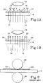
- Fig. 1 schematically illustrates the transmission of light through an image printed on a light-transmissive substrate.
- ink deposited on a light-transmissive substrate 14 solidifies as generally hemispherical ink droplets 12 that refract impinging light beams 10.
- Refracted light beams 16 are generally directed away from a collection lens 18 of a projection system (not shown).
- Substantially all light beams 10 impinging on substrate 14 are therefore transmitted through ink droplets 12 in non-rectilinear paths, even if ink droplets 12 are optically transparent. Consequently, the projected image is visible only in contrast, and the colors thereof have a dull grayish cast. This problem is exacerbated by subtractive color printing techniques wherein multiple layers of droplets 12 are required to produce secondary colors, while primary colors require a single ink droplet 12.
- U.S. Patent No. 4,889,761 discloses substrates having a light-transmissive phase change ink printed thereon that are processed to improve the quality of images projected by overhead projection techniques.
- Printed substrates are processed to reconfigure the surface configuration of solidified phase change ink droplets to provide a printed ink layer, having a generally uniform thickness and capable of transmitting light in a substantially rectilinear path.
- Fig. 1B light beams 10 impinge on ink layer 20 in a generally rectilinear path, producing collimated, rectilinear transmitted light 22 that can be collected by collection lens 18 of a projection system (not shown).
- Reconfiguration is achieved by the application of pressure or a combination of heat and pressure to the printed substrate by means of a dual roller assembly.
- Rollers having various constructions are disclosed, including a TEFLON® coated heated roller and silicone rubber covered pressure roller.
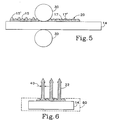
- Fig. 2 schematically shows an exemplary reconfiguration process in progress, wherein generally hemispherical ink droplets 12 have been deposited on light-transmissive substrate 14. Some droplets 12 have been reconfigured by a reconfiguration member 30 to form ink layer 20.
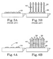
- Fig. 3A schematically depicts the situation where every addressable pixel location of light-transmissive substrate 14 had ink droplets deposited thereon and reconfigured to form ink layer 20.
- This ink layer 20 is characterized by a degree of residual curvature arising from incomplete reconfiguration of generally hemispherical ink droplets.
- Fig. 3B schematically depicts rectilinear transmitted light 22 passing through the reconfigured, closely spaced ink droplets forming ink layer 20.
- the limitation on the reconfiguration of the ink droplets, occasioned by the juxtaposition thereof, produces an ink layer 20 which projects colors of relatively low saturation, evidenced by a relatively small path width 40 of rectilinear transmitted light 22.
- the present invention provides methods of producing improved printed light-transmissive substrates. Such printed substrates are capable of forming projected images of enhanced quality using overhead projection techniques. Improved ink deposition configurations are also contemplated by the present invention.
- Enhanced projected images are produced in accordance with embodiments of the present invention by widening the path width of rectilinear light transmission through a reconfigured ink layer on a light-transmissive substrate.
- Such path widening is achieved by an image thinning process. More specifically, "white” (i.e., non-printed) pixels are introduced into an image to be printed on a light-transmissive substrate.
- the modified printed image is characterized by a less dense ink droplet configuration.
- printed image reconfiguration is more successful, in that droplet-droplet contact is decreased to allow reconfiguration of each ink droplet into a thinner and flatter arrangement.
- Image thinning embodiments of the present invention may be employed with respect to primary or composite colored images.
- One embodiment of the image thinning technique of the present invention involves introducing a white pixel at every other printed pixel location of a densely packed image.
- Another embodiment of the present invention features the use of a linear transformation to achieve image thinning.
- Image thinning techniques employing, for example, gamma tables or alternative image lightening procedures are also useful in accordance with the present invention.
- black pixels preferably to densely packed composite color or large volume primary color images.
- One embodiment of the black pixel addition technique involves introducing a black pixel at every other printed pixel location of a densely packed image. Since composite color images are formed from multiple-layer ink droplet deposition, black pixel addition to such densely packed colored images reduces the volume of ink to be reconfigured, thereby facilitating improved reconfiguration. Improved reconfiguration results in a wider rectilinear light transmission path across each composite color ink droplet. In addition, black pixels do not pass white light, further enhancing the projected composite color image and improving contrast in projected images.
- ink droplet configuration enhancing (printed image modifying) embodiments of the present invention are useable alone or in combination. That is, different printed images or portions of the same printed image may be modified using different embodiments of the present invention.
- the precise implementation of the methods of the present invention depends upon the color and density of the image to be printed on the light-transmissive substrate.
- Image modification in accordance with the present invention can be accomplished at a variety of levels within the printing process. For example, image modification can occur prior to communicating color information to the printer, in a printer application program, in the printer driver, in a printer-embedded high level controller (e.g., a PostScriptTM controller), in a printer-embedded low level controller or a combination thereof.
- a printer-embedded high level controller e.g., a PostScriptTM controller
- printer-embedded low level controller e.g., a printer-embedded low level controller
- Fig. 1A is a schematic representation illustrating the substantially non-rectilinear transmission of light beams from a light projection source through a printed substrate having a printed ink layer.
- Fig. 1B is a schematic representation illustrating the substantially rectilinear transmission of light beams from a light projection source through a printed substrate having a reconfigured printed ink layer.
- Fig. 2 is a schematic representation illustrating a prior art reconfiguration process.
- Fig. 3A is a schematic representation illustrating a prior art reconfigured printed ink layer.
- Fig. 3B is a schematic representation illustrating rectilinear light transmission through the reconfigured printed ink layer shown in Fig. 3A.
- Fig. 4A is a schematic representation illustrating a reconfigured printed ink layer of an embodiment of the present invention.
- Fig. 4B is a schematic representation illustrating rectilinear light transmission through the reconfigured printed ink layer shown in Fig. 4A.
- Fig. 5 is a schematic representation illustrating an embodiment of a reconfiguration process of the present invention, producing a reconfigured printed ink layer embodiment of the present invention.
- Fig. 6 is a schematic representation illustrating rectilinear light transmission through the reconfigured printed ink layer shown in Fig. 5.
- the present invention is directed to the production of printed substrates capable of generating high quality projected images using overhead projection techniques. Improved printed substrates can be produced by increasing the efficiency of reconfiguration processes which alter the shape of printed ink droplets to improve images projectable thereby. Another method to achieve projected image improvement is to enhance the apparent projected colors of a printed substrate generated by a printing or marking technology, wherein the shape of the deposited colors detracts from the apparent saturation of the projected colors.
- the methods of the present invention involve the preparation of printed light-transmissive substrates capable of projecting saturated color images using overhead projection techniques. Projected images of higher saturation are achieved by widening the path width of substantially rectilinear light transmission though the printed substrate. Printed substrates characterized by such rectilinear light transmission path widths are also contemplated by the present invention.
- a "densely packed” image or image portion is one in which from 100% to about 75% of available pixel locations are to be printed.
- a “composite” color for the purposes of the present invention, is a mixture of primary colors.
- One embodiment of the present invention involves the introduction of "white" or non-printed pixels into a densely packed image. Less densely packed or “thinned” printed images can be more effectively reconfigured, because droplet-droplet contact is decreased or avoided.
- a pressure reconfiguration procedure for example, the pressure on each drop is increased because pressure is applied to fewer drops simultaneously, resulting in a reconfigured printed substrate 50 such as schematically shown in Fig. 4A.
- a comparison of Figs. 3A and 4A reveals that the introduction of white pixels results in a flatter (i.e., more parallel to the surface of substrate 14 upon which deposition occurs) and thinner (i.e., the upper ink surface being disposed closer to the deposition surface of substrate 14) ink layer 20. That is, ink layer 20 of reconfigured printed substrate 50 exhibits little or no residual curvature from the non-reconfigured ink droplet printed substrate configuration.
- Fig. 4B shows transmitted rectilinear light 22 passing through reconfigured printed substrate 50.
- Path width 40 of transmitted rectilinear light 22 is wider for reconfigured printed substrate 50 of the present invention than for a reconfigured, densely packed primary color image. Compare Figs. 4B and 3B.
- ink layer 20 of reconfigured printed substrate 50 does not completely cover the surface area of light-transmissive substrate 14, white light 52 passes therethrough when overhead projection techniques are applied to reconfigured printed substrate 50. Such white light 52 transmission does not appreciably adversely impact the saturation of the projected image as a result of the increased amount of transmitted rectilinear light 22 of the appropriate color or colors. Also, white pixel addition can be selected to minimize exposed light-transmissive substrate 14 surface area and, therefore, minimize white light 52 passed therethrough during projection.
- Thinning may be accomplished in any convenient manner therefor.
- a white pixel can be introduced at every other printed pixel location within a densely packed printed image.
- a linear transformation may be employed in the white pixel introduction step.
- the three colors are lightened by 35% and black remains constant. There is no need to thin the black pixels, because an ideal black ink field blocks all light passage through light-transmissive substrate 14.
- Gamma tables or other thinning methodologies can also be employed in the practice of the present invention.
- Figs. 5 and 6 show an embodiment of the present invention involving the addition of black printed pixels to a densely packed composite color image in replacement of a number of composite colored printed pixels.
- Composite colors are those formed by combining two primary colors, which require deposition of a greater volume of ink at a given pixel location than is required to deposit a primary color at that location.
- Fig. 5 shows light-transmissive substrate 14 printed with a plurality of composite ink droplets 15' and a plurality of "primary" black ink droplets 15. Black is a primary color in the sense that only a single ink deposition is required to print black by a printer operating, for example, in CMYK color space.
- ink layer 20 is formed as shown on the right side of Fig. 5. Ink layer 20 is characterized by a plurality of substantially flat composite colored portions 17' and a plurality of substantially hemispherical (i.e., non-reconfigured) black portions 17.
- Fig. 6 shows a reconfigured printed substrate 60 having transmitted rectilinear light 22 passing therethrough at path width 40.
- reconfiguration member 30 acts on a lesser volume of ink than it would if all pixels were printed with composite color ink droplets 15'. Reconfiguring composite color ink droplets 15' encounter less resistance from next or closely adjacent black droplets 15 (in comparison to a next or closely adjacent composite color droplet 15'). As a result, ink layer portions 17' are formed, which exhibit reduced residual curvature when compared to ink layer portions produced when a dense field of composite color ink droplets 15' undergoes reconfiguration. Moreover, the reduced volume of ink to be reconfigured permits more efficient functioning of reorientation member 30.
- Image modification embodiments of the present invention may be accomplished at a variety of levels within the printing process.
- a "high level” approach involves implementation of the image modification process prior to communicating the color information to the printer.
- Image modification may also occur at other levels, including in an application program such as ADOBE ILLUSTRATORTM by Adobe Systems, Inc. of Mountain View, California, in a printer device driver, in a printer-embedded, high level controller such as a PostScriptTM controller, in a print engine-embedded, low level controller or a combination thereof.
- White pixel and black pixel addition embodiments of the present invention can be used alone or in combination. More specifically, white pixel addition may be employed for a first printed image, while black pixel addition may be employed for a second. Alternatively, white pixel addition may be used on one or more portions of a single printed image, while black pixel addition may be employed on one or more different portions of that printed image.
- image modification technique depends upon the color (primary or composite), size of the ink droplets (large volume or standard volume), density of printed pixels and the like. Simple procedures can be implemented to permit a user to select an appropriate image modification, with a set of defaults to apply when no such user selection is made. Alternatively, image modification may be embedded within printer hardware or software.
- Phase change inks useful in accordance with the present invention are solid at ambient temperatures and liquid at printing temperatures. Phase change inks preferably exhibit the following characteristics: low viscosity in the liquid phase; transparency and durability in the solid phase; and malleability at intermediate temperatures to facilitate manipulation. Light-transmissive phase change inks are preferred.
- Suitable light-transmissive substrates 14 are substantially impermeable.
- Light-transmissive substrates 14 useful in the practice of the present invention are known and commercially available, for example, transparency film for Phaser III PXiTM from Tektronix, Inc. of Beaverton, Oregon.
- Ink droplets printed on substantially impermeable substrates are reconfigured in any convenient manner therefor, such that the processed ink layers have generally flat surface conformations.
- Reconfiguration of a printed ink layer can be accomplished by application of pressure alone or during a temperature-controlled operation. Reconfiguration of the printed ink layer is particularly important for image projection by light-transmissive substrates.
- Reconfiguration can be accomplished by elevating the temperature of the printed ink layer to a temperature at which the ink is malleable and simultaneously applying pressure to the printed substrate.
- the printed substrate is preferably supported by a resilient support means during reconfiguration.
- Resilient support means useful in the practice of the present invention are capable of withstanding the application of elevated temperatures and pressures required therefor. Silicone rubber pads having a Durometer of about 50 (Shore A) and a thickness of about 0.2 inches were purchased from McMaster-Carr Supply Company, Catalog No. 8632K15, and performed well in experimental tests.
- Reconfiguration of the ink droplets is accomplished by application of pressure sufficient to reconfigure the malleable ink droplets having various surface conformations to provide an ink layer having one or more substantially flat surface conformations corresponding to areas having different volumes of ink.
- Suitable contact pressures vary depending upon the configuration of the reconfiguration member, but contact pressures of from about 400 to about 4000 psi are generally suitable. Contact pressures of from about 500 to about 800 psi are generally preferred when large contact surfaces are employed. Contact pressures of from about 2500-4000 psi are generally preferred when reconfiguration members having smaller contact surface areas are employed.
Abstract
Description
- The present invention relates generally to methods of printing phase change inks on light-transmissive substrates. More specifically, modified ink deposition methods are applied to light-transmissive substrates, thereby enhancing the effectiveness of subsequent substrate processing and improving the properties of images projected using the printed substrates.
- In general, phase change inks are solid at ambient temperatures and liquid at the elevated operating temperatures of ink jet printing devices. Liquid phase ink droplets are ejected from the printing device at an elevated operating temperature and, when the ink droplets contact the surface of a substrate, they quickly solidify to form a predetermined pattern.
- Phase change ink is advantageous for printing purposes since it remains in solid phase at room temperature during shipping and long-term storage. Also, problems associated with print head nozzle clogging due to ink evaporation are largely eliminated, thereby improving the reliability of ink jet printing. Furthermore, since the ink droplets solidify rapidly upon contact with the substrate, migration of ink along the printing medium is greatly reduced and image quality is improved. Rapid solidification allows high quality images to be printed on a wide variety of printing media.
- Manipulation of printed images formed from substrate deposition of phase change inks, either during or following the printing process, has been conducted. In U.S. Patent No. 4,745,420 of Gerstenmaier, droplets of a phase change ink are ejected onto a target and subsequently spread by the application of pressure to increase the coverage and minimize the volume of ink required. Similarly, in xerographic image fusing, the area of contact between the toner and the substrate is substantially increased by causing the toner to spread and penetrate somewhat into the underlying substrate. The mechanical properties of the toner are such that plastic deformation and flow occur rapidly.
- Hot roll fusing has also been used in toner applications. In hot roll fusing, two rolls (one heated) are mechanically loaded together and rotated to provide transient application of heat and pressure to the substrate. The toner is typically heated to above its glass transition temperature (Tg), which enables it to coalesce, flow, and penetrate the substrate. Rolling pressure and capillary action facilitate coverage.
- Ink jet printing of colored inks onto light-transmissive media for displaying color images by overhead projection has historically been a problem. When aqueous inks are employed, for example, special coatings must be provided on the light-transmissive medium to absorb the solvent so that images of high quality are formed. Even though special coatings are not required on receptor films used for phase change ink jet printing, images produced by prior art color phase change inks printed on light-transmissive substrate materials are not generally acceptable for use in an overhead projection system.
- The development of phase change inks that are substantially transparent, i.e., inks that transmit substantially all of the light that impinges on them, has improved the quality of images printed on light-transmissive substrates. Projection of images printed on light-transmissive substrates using substantially transparent inks is, however, generally unsatisfactory as a consequence of color ink jet printing techniques.
- Fig. 1 schematically illustrates the transmission of light through an image printed on a light-transmissive substrate. As shown in Fig. 1A, ink deposited on a light-
transmissive substrate 14 solidifies as generallyhemispherical ink droplets 12 that refract impinginglight beams 10. Refractedlight beams 16 are generally directed away from acollection lens 18 of a projection system (not shown). Substantially alllight beams 10 impinging onsubstrate 14 are therefore transmitted throughink droplets 12 in non-rectilinear paths, even ifink droplets 12 are optically transparent. Consequently, the projected image is visible only in contrast, and the colors thereof have a dull grayish cast. This problem is exacerbated by subtractive color printing techniques wherein multiple layers ofdroplets 12 are required to produce secondary colors, while primary colors require asingle ink droplet 12. - Another problem that arises in ink jet printing and is evident in projection of phase change ink printed substrates is "banding." As the print head and substrate move relative to one another and the print head deposits successive lines of ink, discrepancies arise in the alignment of adjacent printed lines relative to one another. These alignment discrepancies result in the formation of "bands" in the printed pattern at the interfaces of adjacent printed lines. The bands further detract from the appearance and clarity of a projected image.
- U.S. Patent No. 4,889,761 discloses substrates having a light-transmissive phase change ink printed thereon that are processed to improve the quality of images projected by overhead projection techniques. Printed substrates are processed to reconfigure the surface configuration of solidified phase change ink droplets to provide a printed ink layer, having a generally uniform thickness and capable of transmitting light in a substantially rectilinear path. As shown in Fig. 1B,
light beams 10 impinge onink layer 20 in a generally rectilinear path, producing collimated, rectilinear transmittedlight 22 that can be collected bycollection lens 18 of a projection system (not shown). Reconfiguration is achieved by the application of pressure or a combination of heat and pressure to the printed substrate by means of a dual roller assembly. Rollers having various constructions are disclosed, including a TEFLON® coated heated roller and silicone rubber covered pressure roller. - Fig. 2 schematically shows an exemplary reconfiguration process in progress, wherein generally
hemispherical ink droplets 12 have been deposited on light-transmissive substrate 14. Somedroplets 12 have been reconfigured by areconfiguration member 30 to formink layer 20. - A problem arises when (e.g., pressure or heat/pressure) reconfiguration is conducted upon next adjacent or closely
adjacent ink droplets 12. More specifically, the reconfiguration of oneink droplet 12 encounters resistance from the adjacent, closely spaceddroplet 12 which has not yet been reconfigured. As thedroplet 12 undergoing reconfiguration spreads, it impacts adjacent, closely spaceddroplet 12. This droplet-droplet contact limits the degree to whichink droplets 12 can be reconfigured though action ofreconfiguration member 30. - Fig. 3A schematically depicts the situation where every addressable pixel location of light-
transmissive substrate 14 had ink droplets deposited thereon and reconfigured to formink layer 20. Thisink layer 20 is characterized by a degree of residual curvature arising from incomplete reconfiguration of generally hemispherical ink droplets. Fig. 3B schematically depicts rectilinear transmittedlight 22 passing through the reconfigured, closely spaced ink droplets formingink layer 20. The limitation on the reconfiguration of the ink droplets, occasioned by the juxtaposition thereof, produces anink layer 20 which projects colors of relatively low saturation, evidenced by a relativelysmall path width 40 of rectilinear transmittedlight 22. - The present invention provides methods of producing improved printed light-transmissive substrates. Such printed substrates are capable of forming projected images of enhanced quality using overhead projection techniques. Improved ink deposition configurations are also contemplated by the present invention.
- Enhanced projected images are produced in accordance with embodiments of the present invention by widening the path width of rectilinear light transmission through a reconfigured ink layer on a light-transmissive substrate. Such path widening is achieved by an image thinning process. More specifically, "white" (i.e., non-printed) pixels are introduced into an image to be printed on a light-transmissive substrate. In this manner, the modified printed image is characterized by a less dense ink droplet configuration. As a result, printed image reconfiguration is more successful, in that droplet-droplet contact is decreased to allow reconfiguration of each ink droplet into a thinner and flatter arrangement. Image thinning embodiments of the present invention may be employed with respect to primary or composite colored images.
- One embodiment of the image thinning technique of the present invention involves introducing a white pixel at every other printed pixel location of a densely packed image. Another embodiment of the present invention features the use of a linear transformation to achieve image thinning. For a 35% thinning of a CMYK (i.e., cyan, magenta, yellow and black) color space image, for example, a suitable linear transformation is C,M,Y,K -> C',M',Y',K' where C'=0.65C, M'=0.65M, Y'=O.65Y and K'=K. Image thinning techniques employing, for example, gamma tables or alternative image lightening procedures are also useful in accordance with the present invention.
- Other improved projected image ink/substrate embodiments of the present invention involve the addition of black pixels, preferably to densely packed composite color or large volume primary color images. One embodiment of the black pixel addition technique involves introducing a black pixel at every other printed pixel location of a densely packed image. Since composite color images are formed from multiple-layer ink droplet deposition, black pixel addition to such densely packed colored images reduces the volume of ink to be reconfigured, thereby facilitating improved reconfiguration. Improved reconfiguration results in a wider rectilinear light transmission path across each composite color ink droplet. In addition, black pixels do not pass white light, further enhancing the projected composite color image and improving contrast in projected images.
- The ink droplet configuration enhancing (printed image modifying) embodiments of the present invention are useable alone or in combination. That is, different printed images or portions of the same printed image may be modified using different embodiments of the present invention. The precise implementation of the methods of the present invention depends upon the color and density of the image to be printed on the light-transmissive substrate.
- Image modification in accordance with the present invention can be accomplished at a variety of levels within the printing process. For example, image modification can occur prior to communicating color information to the printer, in a printer application program, in the printer driver, in a printer-embedded high level controller (e.g., a PostScript™ controller), in a printer-embedded low level controller or a combination thereof. The present invention will now be described in terms of preferred embodiments thereof, reference being made to the accompanying drawings, in which:-
- Fig. 1A is a schematic representation illustrating the substantially non-rectilinear transmission of light beams from a light projection source through a printed substrate having a printed ink layer.
- Fig. 1B is a schematic representation illustrating the substantially rectilinear transmission of light beams from a light projection source through a printed substrate having a reconfigured printed ink layer.
- Fig. 2 is a schematic representation illustrating a prior art reconfiguration process.
- Fig. 3A is a schematic representation illustrating a prior art reconfigured printed ink layer.
- Fig. 3B is a schematic representation illustrating rectilinear light transmission through the reconfigured printed ink layer shown in Fig. 3A.
- Fig. 4A is a schematic representation illustrating a reconfigured printed ink layer of an embodiment of the present invention.
- Fig. 4B is a schematic representation illustrating rectilinear light transmission through the reconfigured printed ink layer shown in Fig. 4A.
- Fig. 5 is a schematic representation illustrating an embodiment of a reconfiguration process of the present invention, producing a reconfigured printed ink layer embodiment of the present invention.
- Fig. 6 is a schematic representation illustrating rectilinear light transmission through the reconfigured printed ink layer shown in Fig. 5.
- The present invention is directed to the production of printed substrates capable of generating high quality projected images using overhead projection techniques. Improved printed substrates can be produced by increasing the efficiency of reconfiguration processes which alter the shape of printed ink droplets to improve images projectable thereby. Another method to achieve projected image improvement is to enhance the apparent projected colors of a printed substrate generated by a printing or marking technology, wherein the shape of the deposited colors detracts from the apparent saturation of the projected colors.
- While discussed below in relationship to ink jet printers, the principles of the present invention find application in color laser printers, dot matrix impact printers, color laser copiers and the like.
- The methods of the present invention involve the preparation of printed light-transmissive substrates capable of projecting saturated color images using overhead projection techniques. Projected images of higher saturation are achieved by widening the path width of substantially rectilinear light transmission though the printed substrate. Printed substrates characterized by such rectilinear light transmission path widths are also contemplated by the present invention.
- For the purposes of the present invention, a "densely packed" image or image portion is one in which from 100% to about 75% of available pixel locations are to be printed. A "composite" color, for the purposes of the present invention, is a mixture of primary colors.
- One embodiment of the present invention involves the introduction of "white" or non-printed pixels into a densely packed image. Less densely packed or "thinned" printed images can be more effectively reconfigured, because droplet-droplet contact is decreased or avoided. In a pressure reconfiguration procedure, for example, the pressure on each drop is increased because pressure is applied to fewer drops simultaneously, resulting in a reconfigured printed
substrate 50 such as schematically shown in Fig. 4A. A comparison of Figs. 3A and 4A reveals that the introduction of white pixels results in a flatter (i.e., more parallel to the surface ofsubstrate 14 upon which deposition occurs) and thinner (i.e., the upper ink surface being disposed closer to the deposition surface of substrate 14)ink layer 20. That is,ink layer 20 of reconfigured printedsubstrate 50 exhibits little or no residual curvature from the non-reconfigured ink droplet printed substrate configuration. - Fig. 4B shows transmitted rectilinear light 22 passing through reconfigured printed
substrate 50.Path width 40 of transmittedrectilinear light 22 is wider for reconfigured printedsubstrate 50 of the present invention than for a reconfigured, densely packed primary color image. Compare Figs. 4B and 3B. - Because
ink layer 20 of reconfigured printedsubstrate 50 does not completely cover the surface area of light-transmissive substrate 14,white light 52 passes therethrough when overhead projection techniques are applied to reconfigured printedsubstrate 50. Suchwhite light 52 transmission does not appreciably adversely impact the saturation of the projected image as a result of the increased amount of transmittedrectilinear light 22 of the appropriate color or colors. Also, white pixel addition can be selected to minimize exposed light-transmissive substrate 14 surface area and, therefore, minimizewhite light 52 passed therethrough during projection. - Thinning may be accomplished in any convenient manner therefor. For example, a white pixel can be introduced at every other printed pixel location within a densely packed printed image. Alternatively, a linear transformation may be employed in the white pixel introduction step. For example, a 35% thinning of printed pixels for an image rendered in CMYK (cyan, magenta, yellow and black) color space is accomplished using the following linear transformation:
C, M, Y, K -> C',M',Y',K' , where C'=0.65C, M'=0.65M, Y'=0.65Y' and K'=K. - In this example, the three colors are lightened by 35% and black remains constant. There is no need to thin the black pixels, because an ideal black ink field blocks all light passage through light-
transmissive substrate 14. Gamma tables or other thinning methodologies can also be employed in the practice of the present invention. - Figs. 5 and 6 show an embodiment of the present invention involving the addition of black printed pixels to a densely packed composite color image in replacement of a number of composite colored printed pixels. Composite colors are those formed by combining two primary colors, which require deposition of a greater volume of ink at a given pixel location than is required to deposit a primary color at that location.
- The left side of Fig. 5 shows light-
transmissive substrate 14 printed with a plurality of composite ink droplets 15' and a plurality of "primary"black ink droplets 15. Black is a primary color in the sense that only a single ink deposition is required to print black by a printer operating, for example, in CMYK color space. After reconfiguration withreconfiguration member 30,ink layer 20 is formed as shown on the right side of Fig. 5.Ink layer 20 is characterized by a plurality of substantially flat composite colored portions 17' and a plurality of substantially hemispherical (i.e., non-reconfigured)black portions 17. Fig. 6 shows a reconfigured printedsubstrate 60 having transmitted rectilinear light 22 passing therethrough atpath width 40. - Because
black ink droplets 15 require the deposition of less ink than composite color ink droplets 15',reconfiguration member 30 acts on a lesser volume of ink than it would if all pixels were printed with composite color ink droplets 15'. Reconfiguring composite color ink droplets 15' encounter less resistance from next or closely adjacent black droplets 15 (in comparison to a next or closely adjacent composite color droplet 15'). As a result, ink layer portions 17' are formed, which exhibit reduced residual curvature when compared to ink layer portions produced when a dense field of composite color ink droplets 15' undergoes reconfiguration. Moreover, the reduced volume of ink to be reconfigured permits more efficient functioning ofreorientation member 30. - Also, as shown in Fig. 4B, addition of white pixels can result in
white light 52 passing through reconfigured printedsubstrate 50, thereby reducing the saturation of a projected image. This is not the case when black pixel addition is undertaken. Black pixels block light transmission through reconfigured printedsubstrate 60 as shown in Fig. 6, thereby eliminating the adverse impact of white light on projected color saturation. - Image modification embodiments of the present invention may be accomplished at a variety of levels within the printing process. A "high level" approach involves implementation of the image modification process prior to communicating the color information to the printer. Image modification may also occur at other levels, including in an application program such as ADOBE ILLUSTRATOR™ by Adobe Systems, Inc. of Mountain View, California, in a printer device driver, in a printer-embedded, high level controller such as a PostScript™ controller, in a print engine-embedded, low level controller or a combination thereof.
- White pixel and black pixel addition embodiments of the present invention can be used alone or in combination. More specifically, white pixel addition may be employed for a first printed image, while black pixel addition may be employed for a second. Alternatively, white pixel addition may be used on one or more portions of a single printed image, while black pixel addition may be employed on one or more different portions of that printed image.
- The choice of image modification technique depends upon the color (primary or composite), size of the ink droplets (large volume or standard volume), density of printed pixels and the like. Simple procedures can be implemented to permit a user to select an appropriate image modification, with a set of defaults to apply when no such user selection is made. Alternatively, image modification may be embedded within printer hardware or software.
- Phase change inks useful in accordance with the present invention are solid at ambient temperatures and liquid at printing temperatures. Phase change inks preferably exhibit the following characteristics: low viscosity in the liquid phase; transparency and durability in the solid phase; and malleability at intermediate temperatures to facilitate manipulation. Light-transmissive phase change inks are preferred.
- Suitable light-transmissive substrates 14 (e.g., polymeric films including polyester films) are substantially impermeable. Light-
transmissive substrates 14 useful in the practice of the present invention are known and commercially available, for example, transparency film for Phaser III PXi™ from Tektronix, Inc. of Beaverton, Oregon. - Ink droplets printed on substantially impermeable substrates are reconfigured in any convenient manner therefor, such that the processed ink layers have generally flat surface conformations. Reconfiguration of a printed ink layer can be accomplished by application of pressure alone or during a temperature-controlled operation. Reconfiguration of the printed ink layer is particularly important for image projection by light-transmissive substrates.
- Reconfiguration can be accomplished by elevating the temperature of the printed ink layer to a temperature at which the ink is malleable and simultaneously applying pressure to the printed substrate. The printed substrate is preferably supported by a resilient support means during reconfiguration. Resilient support means useful in the practice of the present invention are capable of withstanding the application of elevated temperatures and pressures required therefor. Silicone rubber pads having a Durometer of about 50 (Shore A) and a thickness of about 0.2 inches were purchased from McMaster-Carr Supply Company, Catalog No. 8632K15, and performed well in experimental tests.
- Reconfiguration of the ink droplets is accomplished by application of pressure sufficient to reconfigure the malleable ink droplets having various surface conformations to provide an ink layer having one or more substantially flat surface conformations corresponding to areas having different volumes of ink. Suitable contact pressures vary depending upon the configuration of the reconfiguration member, but contact pressures of from about 400 to about 4000 psi are generally suitable. Contact pressures of from about 500 to about 800 psi are generally preferred when large contact surfaces are employed. Contact pressures of from about 2500-4000 psi are generally preferred when reconfiguration members having smaller contact surface areas are employed.
- While in the foregoing specification, this invention has been described in relation to certain preferred embodiments thereof, and many details have been set forth for purposes of illustration, it will be apparent to those skilled in the art that the invention is susceptible to additional embodiments and that certain of the details described herein may be varied considerably without departing from the basic principles of the invention.
Claims (21)
- An image carrier precursor for an image carrier to be used in an overhead colour projection system, the image carrier comprising a light-transmissive substrate ink jet printed with a phase change ink layer forming an image comprising reconfigured deposited phase change ink droplets at printed pixel locations of the substrate and the image carrier precursor comprising an interim image formed by unreconfigured deposited phase change ink droplets at said pixel locations, characterized by the pixels of the substrate being addressed with coloured ink droplets as to some pixels and being white pixels as to others adjacent to coloured pixels and/or black pixels as to others adjacent composite colour pixels or other large volume primary colour pixels whereby the phase change ink deposition configuration is of reduced volume relative to a substrate whose interim image is composed of pixels all printed with coloured droplets and whereby reconfiguration of the reduced volume ink deposition configuration can be effected in relation to the droplets in the precursor in order to modify the droplets with reduced resistance to droplet modification demonstrated by adjacent pixels.
- A method of producing printed light-transmissive substrates for use in an overhead projection system, the method comprising the steps of:-(i) modifying an original ink deposition configuration to introduce a plurality of white pixels therein to form a reduced density ink deposition configuration;(ii) depositing the reduced density ink deposition configuration; and(iii) reconfiguring the reduced density ink deposition configuration to form a printed image capable of projecting saturated colours.
- A method as claimed in Claim 2 and comprising the step of communicating colour information to a printer after the modifying step.
- A method of Claim 2 or Claim 3 wherein the modifying step is implemented using a linear transformation.
- A method as claimed in Claim 4 wherein the linear transformation involves a value ranging from about 50% to about 100%.
- A method as claimed in any one of Claims 2 to 5 wherein the modifying step is implemented in a printer driver, in a printer application program, in a high level printer controller, in a low level printer controller or a combination thereof.
- A method as claimed in any one of Claims 2 to 6 wherein the modifying step comprises an introduction of a plurality of black pixels in an area of the original ink deposition configuration formed on densely packed composite colours or large volume primary colours.
- A method of producing printed light-transmissive substrates for use in an overhead projection system, the method comprising the steps of:-(i) modifying an original ink deposition configuration characterized by densely packed composite colour or large volume primary colour pixels to introduce a plurality of black pixels therein to form a reduced volume ink deposition configuration;(i) depositing the reduced volume ink deposition configuration; and(iii) reconfiguring the reduced volume ink deposition configuration to form a printed image capable of projecting saturated colours.
- A method as claimed in Claim 8 and comprising the step of communicating colour information to a printer after the modifying step.
- A method as claimed in Claim 8 or Claim 9 wherein a black pixel is introduced at every other printed pixel location in the original ink deposition configuration.
- A method as claimed in any one of Claims 8 to 10 wherein the modifying step is implemented in a printer driver, in a printer application program, in a high level printer controller, in a low level printer controller or a combination thereof.
- A method as claimed in any one of Claims 8 to 11 wherein the modifying step comprises an introduction of a plurality of white pixels in an area of the original ink deposition configuration formed of densely packed primary colours of substantially standard volume.
- A printed image capable of image reconfiguration and projection by an overhead projection technique and comprising:-(i) a light-transmissive substrate; and(ii) a modified ink deposition configuration deposited upon the light-transmissive substrate, wherein the modified ink deposition configuration comprises an original ink deposition configuration modified to introduce a plurality of white pixels therein to form a reduced density printed image which is capable of more complete image reconfiguration to form a reconfigured printed image having an ink layer exhibiting reduced residual curvature.
- A printed image as claimed in Claim 13 wherein the original ink deposition configuration is modified using a linear transformation.
- A printed image as claimed in Claim 14 wherein the linear transformation involves a value ranging from about 50% to about 100%.
- A printed image as claimed in any one of Claims 13 to 15 wherein the original ink deposition configuration comprises a densely packed primary colour configuration.
- A printed image as claimed in any one of Claims 13 to 16 which further comprises an original ink deposition configuration modified to introduce a plurality of black pixels therein to form a reduced volume printed image at pixel locations corresponding to a densely packed composite colour or a large volume primary colour configuration.
- A printed image capable of image reconfiguration and projection by an overhead projection technique and comprising:-(i) a light-transmissive substrate; and(ii) a modified ink deposition configuration deposited upon the light-transmissive substrate, wherein the modified ink deposition configuration comprises an original ink deposition configuration modified to introduce a plurality of black pixels therein to form a reduced volume printed image which is capable of more complete image reconfiguration to form a reconfigured printed image having an ink layer exhibiting reduced residual curvature.
- A printed image as claimed in Claim 18 wherein the original ink deposition configuration comprises a densely packed composite colour or large volume primary colour configuration.
- A printed image as claimed in Claim 18 or Claim 19 which comprises an original ink deposition configuration modified to introduce a plurality of white pixels therein to form a reduced density printed image at pixel locations of densely packed, substantially standard volume primary colours.
- A printed image as claimed in any one of Claims 18 to 20 wherein the original ink deposition configuration is modified by introducing a black pixel at every other printed pixel location thereof.
Applications Claiming Priority (2)
| Application Number | Priority Date | Filing Date | Title |
|---|---|---|---|
| US90325592A | 1992-06-23 | 1992-06-23 | |
| US903255 | 1992-06-23 |
Publications (2)
| Publication Number | Publication Date |
|---|---|
| EP0576261A2 true EP0576261A2 (en) | 1993-12-29 |
| EP0576261A3 EP0576261A3 (en) | 1994-06-01 |
Family
ID=25417191
Family Applications (1)
| Application Number | Title | Priority Date | Filing Date |
|---|---|---|---|
| EP19930304878 Withdrawn EP0576261A3 (en) | 1992-06-23 | 1993-06-22 | Improved phase change ink printing on light-transmissive substrates |
Country Status (2)
| Country | Link |
|---|---|
| EP (1) | EP0576261A3 (en) |
| JP (1) | JPH08473B2 (en) |
Citations (4)
| Publication number | Priority date | Publication date | Assignee | Title |
|---|---|---|---|---|
| EP0013296A2 (en) * | 1978-11-13 | 1980-07-23 | International Business Machines Corporation | Multiple speed ink jet printer |
| EP0144016A2 (en) * | 1983-11-30 | 1985-06-12 | Kabushiki Kaisha Toshiba | Dot-matrix printer |
| US4721968A (en) * | 1983-09-22 | 1988-01-26 | Canon Kabushiki Kaisha | Ink jet transparency-mode recorder |
| US4889761A (en) * | 1988-08-25 | 1989-12-26 | Tektronix, Inc. | Substrates having a light-transmissive phase change ink printed thereon and methods for producing same |
-
1993
- 1993-06-22 EP EP19930304878 patent/EP0576261A3/en not_active Withdrawn
- 1993-06-23 JP JP5176069A patent/JPH08473B2/en not_active Expired - Lifetime
Patent Citations (4)
| Publication number | Priority date | Publication date | Assignee | Title |
|---|---|---|---|---|
| EP0013296A2 (en) * | 1978-11-13 | 1980-07-23 | International Business Machines Corporation | Multiple speed ink jet printer |
| US4721968A (en) * | 1983-09-22 | 1988-01-26 | Canon Kabushiki Kaisha | Ink jet transparency-mode recorder |
| EP0144016A2 (en) * | 1983-11-30 | 1985-06-12 | Kabushiki Kaisha Toshiba | Dot-matrix printer |
| US4889761A (en) * | 1988-08-25 | 1989-12-26 | Tektronix, Inc. | Substrates having a light-transmissive phase change ink printed thereon and methods for producing same |
Also Published As
| Publication number | Publication date |
|---|---|
| JPH06262843A (en) | 1994-09-20 |
| JPH08473B2 (en) | 1996-01-10 |
| EP0576261A3 (en) | 1994-06-01 |
Similar Documents
| Publication | Publication Date | Title |
|---|---|---|
| JP4059629B2 (en) | Inkjet printing method | |
| EP0904206B1 (en) | Display unit and methods of displaying an image | |
| US5277501A (en) | Method for transferring hot-melt ink to a recording medium | |
| EP0401878B1 (en) | Ink ribbon for sublimation transfer type hard copy | |
| JP2013242590A (en) | Uv inkjet printing of vision control panel | |
| CN101855092B (en) | Method of printing | |
| JP2929061B2 (en) | Printing method, apparatus and system | |
| CA2459798A1 (en) | Technique for printing a color image | |
| CN100578575C (en) | Method of backlight display printing | |
| JPH04234664A (en) | Arranging method for ink to improve image forming | |
| US20020196325A1 (en) | Laser-induced thermal imaging with masking | |
| JPH10151772A (en) | Ink-jet printer apparatus and ink-jet printing method | |
| JPH0640061A (en) | Printing method by variable intensity printing apparatus | |
| US5196241A (en) | Method for processing substrates printed with phase-change inks | |
| US6943816B2 (en) | Laser-induced thermal imaging with masking | |
| WO2018148027A1 (en) | Variable color printing method and system | |
| EP0576261A2 (en) | Improved phase change ink printing on light-transmissive substrates | |
| US9211746B1 (en) | Hybrid printer for printing on non-porous media | |
| US6121370A (en) | Color recording liquids, cartridges, recording methods and devices | |
| JPH05185628A (en) | Method for thermal printing of large image by using small dye donor patch, apparatus for using this print and method for using this method for printing | |
| CN109203749B (en) | Method for printing on an absorbent printing material with the aid of an ink and a dampening agent | |
| US6010590A (en) | Surface coating on a substrate for printing a high quality image thereon and method of providing same | |
| JP2004142277A (en) | Imitation die stamping method | |
| KR20030055131A (en) | Thermal transfer recording apparatus, thermal transfer recording process and ink sheet | |
| GB2373217A (en) | Inkjet printing system having print heads which utilise at least two different print head technologies |
Legal Events
| Date | Code | Title | Description |
|---|---|---|---|
| PUAI | Public reference made under article 153(3) epc to a published international application that has entered the european phase |
Free format text: ORIGINAL CODE: 0009012 |
|
| AK | Designated contracting states |
Kind code of ref document: A2 Designated state(s): DE FR GB IT |
|
| PUAL | Search report despatched |
Free format text: ORIGINAL CODE: 0009013 |
|
| RHK1 | Main classification (correction) |
Ipc: B41J 2/205 |
|
| AK | Designated contracting states |
Kind code of ref document: A3 Designated state(s): DE FR GB IT |
|
| 17P | Request for examination filed |
Effective date: 19940624 |
|
| 17Q | First examination report despatched |
Effective date: 19951016 |
|
| STAA | Information on the status of an ep patent application or granted ep patent |
Free format text: STATUS: THE APPLICATION IS DEEMED TO BE WITHDRAWN |
|
| 18D | Application deemed to be withdrawn |
Effective date: 19960429 |