EP0576175B1 - Liquid discharging apparatus and printing method using such an apparatus - Google Patents
Liquid discharging apparatus and printing method using such an apparatus Download PDFInfo
- Publication number
- EP0576175B1 EP0576175B1 EP93304493A EP93304493A EP0576175B1 EP 0576175 B1 EP0576175 B1 EP 0576175B1 EP 93304493 A EP93304493 A EP 93304493A EP 93304493 A EP93304493 A EP 93304493A EP 0576175 B1 EP0576175 B1 EP 0576175B1
- Authority
- EP
- European Patent Office
- Prior art keywords
- liquid
- cleaning member
- printing
- head
- ink
- Prior art date
- Legal status (The legal status is an assumption and is not a legal conclusion. Google has not performed a legal analysis and makes no representation as to the accuracy of the status listed.)
- Expired - Lifetime
Links
Images


Classifications
-
- B—PERFORMING OPERATIONS; TRANSPORTING
- B41—PRINTING; LINING MACHINES; TYPEWRITERS; STAMPS
- B41J—TYPEWRITERS; SELECTIVE PRINTING MECHANISMS, i.e. MECHANISMS PRINTING OTHERWISE THAN FROM A FORME; CORRECTION OF TYPOGRAPHICAL ERRORS
- B41J2/00—Typewriters or selective printing mechanisms characterised by the printing or marking process for which they are designed
- B41J2/005—Typewriters or selective printing mechanisms characterised by the printing or marking process for which they are designed characterised by bringing liquid or particles selectively into contact with a printing material
- B41J2/01—Ink jet
- B41J2/135—Nozzles
- B41J2/165—Preventing or detecting of nozzle clogging, e.g. cleaning, capping or moistening for nozzles
- B41J2/16517—Cleaning of print head nozzles
- B41J2/16552—Cleaning of print head nozzles using cleaning fluids
-
- B—PERFORMING OPERATIONS; TRANSPORTING
- B41—PRINTING; LINING MACHINES; TYPEWRITERS; STAMPS
- B41J—TYPEWRITERS; SELECTIVE PRINTING MECHANISMS, i.e. MECHANISMS PRINTING OTHERWISE THAN FROM A FORME; CORRECTION OF TYPOGRAPHICAL ERRORS
- B41J3/00—Typewriters or selective printing or marking mechanisms characterised by the purpose for which they are constructed
- B41J3/407—Typewriters or selective printing or marking mechanisms characterised by the purpose for which they are constructed for marking on special material
- B41J3/4078—Printing on textile
Definitions
- the present invention relates to a liquid discharging apparatus using a liquid discharging head to discharge ink and other liquids and a printing method using such an apparatus. More particularly, the invention relates to a printing apparatus and a printing method whereby to perform a given printing for a paper, cloth, unwoven cloth, OHP sheet, and other printing media. Furthermore, the present invention is effectively applicable to the provision of a printing apparatus capable of continuously printing a cloth having a printing width of one meter or more for a long period of time. The present invention is applicable to various office equipment and mass-processing equipment such as printers, copying machines, facsimile apparatuses, and word processors.
- a conventional liquid discharging apparatus there is the apparatus which performs the printing by discharging a liquid or utilizes a special liquid by discharging it.
- the discharging head which discharges a liquid is extremely small.
- the dyestuff or pigment mixed in a liquid solidifies or foreign particles adhering to the head block the liquid to be discharged, leading to the defective printing of the printing apparatus, a problem that the discharging liquid cannot be utilized efficiently.
- suction, pressurization known as recovery means, is provided which is operated at appropriate intervals in order to cause the liquid to be forcibly exhausted, the discharging area in the discharging ports to be cleaned, or to eject air or liquid to the discharging area in the discharging ports for cleaning.
- the exceedingly viscous ink adheres to the vicinity of the nozzles of the discharging head, thus tending to create clogging or the disabled ink discharging.
- the head surface should be wiped off by a resilient rubber blade, but when an operation must be continued for long hours to meet an industrial requirement, there is a possibility that the wiped-off ink is accumulated without any particular place to dispose of it and becomes an exceedingly viscous ink.
- the discharging head is rubbed by a blade to which such an exceedingly viscous ink adheres, and in such a case, the disabled discharging is invited instead after all Particularly, when a colour printing apparatus is used, the spray is collected from its four heads, the problem of extraneous liquid is more in evidence.
- the present invention is designed to solve the above-mentioned problems. It is an object of the invention to provide a liquid discharging apparatus and a printing method using such an apparatus capable of enhancing the cleaning effect for the liquid discharging ports of the liquid discharging head of the apparatus so that a stable liquid discharging is possible for a long time.
- EP-A-0,446,885 discloses an ink jet recording apparatus for discharging ink to perform recording comprising a carriage member for mounting recording means for discharging ink, a cleaning member arranged to face the regions other than the region for the aforesaid recording means to clean the discharging port formation face of the aforesaid recording means, transporting means for transporting the aforesaid cleaning member to a position to clean recording means and a position not to clean it, and driving means for relatively driving the aforesaid carriage member and transporting means for the aforesaid cleaning member to clean the aforesaid discharging port formation face.
- the aforesaid cleaning member is provided with a first cleaning member (2a) mainly used for cleaning the discharging port formation portion of the aforesaid recording means and a second cleaning member (2b) mainly used for cleaning the circumference of the aforesaid discharging port formation portion.
- US-A-4,296,418 discloses an ink jet printing apparatus in which an ink clog is automatically sensed in an ink ejection nozzle. The clog is cleared by moving a cap into covering engagement with the nozzle orifice, causing solvent to flow trough the nozzle from the cap to dissolve the clogged ink and subsequently causing air to flow through the cap and nozzle to purge solvent therefrom.
- a recording apparatus for use with a liquid discharging head for discharging recording liquid, and comprising: a cleaning member capable of holding a rinsing liquid to clean the liquid discharging ports of said liquid discharging head; characterised by rinsing liquid supplying means for supplying a rinsing liquid to said cleaning member; and rinsing liquid exhausting means to enable at least part of any rinsing liquid present in the cleaning member to be exhausted and to create a liquid absorptive force in said cleaning member.
- a method for printing by use of a liquid discharging head which prints by discharging a recording liquid onto a printing medium comprising the steps of: providing a cleaning member capable of holding a rinsing liquid to clean the liquid discharging ports of said liquid discharging head; supplying a rinsing liquid to said cleaning member; exhausting part of the rinsing liquid in the cleaning member to cause said cleaning member to create a liquid absorptive force; bringing said cleaning member and the liquid discharging ports of said liquid discharging head into abutting relationship when the rinsing liquid is held in said cleaning member and the liquid absorptive force is created in said cleaning member; parting said cleaning member and the liquid discharging ports of said liquid discharging head; and printing by discharging recording liquid from said liquid discharging head onto a printing medium.
- the textiles include woven cloth, unwoven cloth, and clothes and nets irrespective of materials.
- the above-mentioned wall papers include the adhesive materials used for covering the walls using paper, textile, synthetic resin sheet as its material.
- printing is meant to include a “textile printing” and a “recording”, and it does not confine the purpose of the printing in any sense. It widely includes providing printing media with images.
- a liquid discharging head which discharges a bleaching agent to decolor ink, for example, in addition to the liquid discharging head to discharge ink to a printing medium. This is used to locally bleach the part which is deeply dyed by ink.
- a liquid discharging head to discharge an interfacial active agent for processing clothes, protecting the surface of textiles, or to discharge a coating agent to coat the surface of textiles in order to prevent ink from adhering locally thereto.
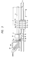
- Fig. 3 and Fig. 9 are views illustrating an example wherein a liquid discharging apparatus according to the present invention is applied to a serial type ink jet printing apparatus.
- a carriage 1 mounts on it color printing heads 2a, 2b, 2c, and 2d respectively for four colors, cyan, magenta, yellow, and black, and a guide shaft 3 supports and guides the carriage 1 movably.
- Reference numerals 22a, 22b, 22c, and 22d designate the discharging surface of each printing head, respectively.
- a belt 4 which is an endless belt is partially connected to the carriage 1.
- the carriage 1 is driven by a driving motor 5 which is a pulse motor driven by a motor driver 23.
- a driving motor 5 which is a pulse motor driven by a motor driver 23.
- the carriage is moved on the guide shaft 3 through the belt 4 along the printing surface of a printing sheet 6.
- a feed roller 7 to feed a printing sheet 6, guide rollers 8A and 8B to guide the printing sheet 6, and a printing sheet feed motor 9.
- a liquid passage 10 is arranged to discharge ink toward the printing sheet 6.
- ink is supplied from each of the ink tanks 11a, 11b, 11c, and 11d corresponding to each of the printing heads 2a, 2b, 2c, and 2d through each of the supply tubes 12a, 12b, 12c, and 12d.
- energy generating means which is not shown
- ink discharging signals are selectively supplied from each of the head drivers 24a, 24b, 24c, and 24d through each of the flexible cables 13a, 13b, 13c, and 13d.
- head heaters 14a, 14b, 14c, and 14d (14b, 14c, and 15d are not shown) and temperature detecting means 15a, 15b, 15c, and 15d (15b, 15c, and 15d are not shown) are provided, respectively.
- the detected signals from the temperature detecting means 15a, 15b, 15c, and 15d are inputted into a control circuit 16 having a CPU.
- the control circuit 16 controls the heating in the head heaters 14a, 14b, 14c, and 14d on the basis of these signals through a driver 17 and a power source 18.
- Capping means 20 are butted to the discharging port surface of each of the printing heads 2a, 2b, 2c, and 2d when the printing is at rest.
- the printing heads 2a, 2b, 2c, and 2d are shifted to a position opposite to the capping means 20 when the printing is at rest.
- the capping means 20 is driven forward by means of a cap driver 25 to perform the capping by allowing a resilient member 44 to but the discharging port surface.
- the ink in the nozzles are evaporated to make it exceedingly viscous, leading to an unstable discharging.
- the nozzle unit is sealed from the atmosphere and airtightly enclosed (capped) when the printing is at rest.
- a liquid absorbent kept sufficiently wet by ink is provided to suppress the increase of the ink viscosity as much as possible by maintaining the inside of the cap highly moisturized.
- an electromagnetic valve 61 for water discharging and an air pump driver 62 are connected to the capping means 20.
- the rinse water discharging nozzle and the air ejection nozzle arranged in the capping means 20 are driven under the control of a control circuit 16, respectively. Also, the ink, foreign particles, and others adhering to or fixed to the head surface are cleaned by the liquid flow and air stream ejected from each of the nozzles.
- the above-mentioned flow of the ejected liquid eases the state of the fixed particles and removes them or cause them to be in a removable condition. This is effectively applicable to the minute parts.
- the above-mentioned ejected air stream removes from the head surface the remaining liquid itself after its ejection, thus making it possible to implement the promotion of the recovery action for the particles in the removable state as well as the liquid. From the nozzle arranged in the upper part of the flow ejection cap, the air stream is blown toward the surface of the nozzles to blow the particles and liquid down to the lower part of the printing head.
- a recovery is also conducted by pressurizing the ink.
- the ink in the nozzles is being evaporated gradually even if the head is capped and it becomes exceedingly viscous.
- air bubbles remain in the nozzles occasionally to hinder a stabilized discharging in some cases. Therefore, when a printing is started, a pump arranged in the ink tank is driven to pressurize the ink to cause any exceedingly viscous ink and residual air bubbles in the nozzles to be exhausted outside the nozzles. This is also effective in washed away the dust particles or fluffs adhering to the nozzle surface or the dust particles which may be present in the nozzles for the maintenance of a stabilized discharging.
- Clogging prevention means 31 receives the discharged ink when the printing heads 2a, 2b, 2c, and 2d perform its preliminary discharging operation.
- the clogging prevention means 31 is arranged to face the printing heads 2a, 2b, 2c, and 2d, and is provided with a liquid receiving member 32 as a liquid receptacle to absorb the ink which is preliminarily discharged.
- This means is arranged between the capping means 20 and a position to start the printing. In this respect, for the materials of the liquid receiving member 32 and a liquid holding member 45, it is effective to adopt a spongy porous material or sintered plastic among others.
- the preliminary discharge is an ink discharging without any particular purpose of printing itself. This discharge is conducted to assure the temperature of the area the temperature of which is lowered due to the ejected liquid flow and ejected air stream as well as to remove any unwanted particles in the discharging ports. Also, besides this, given driving pulses are provided before the printing is started to cause the ink to be discharged from the entire nozzles towards the capping unit and others (aging operation) or in some cases, this is performed while in the capping state if it is desired to enhance the wetting condition of the atmosphere surrounding the nozzles.
- an electromagnetic valve 51 for rinsing and a suction pump driver 52 are connected, and perform under control of the control circuit 16 the discharge of rinsing liquid from rinsing means 53, and the suction of rinsing liquid form the cleaning means 50, respectively.
- rinsing liquid water is used, for example.
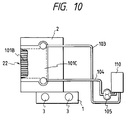
- FIG. 10 shows the structural example of a liquid discharging head.
- a reference numeral 2 designates a discharging head; 22, its discharging port surface; 101B, the nozzle unit in which a plurality of liquid passages are arranged in parallel in the vertical direction, and the discharging energy generating elements such as electrothermal transducers are provided; and 101C, an ink chamber to share the ink supply to each of the liquid passages, which connects them with an ink tank 110 through supply tubes 103 and 104.
- a gear pump 105 is provided to pressurize the ink in the ink supply system to the printing head 2 and cause the ink to be exhausted from the discharging ports when the air bubbles and particles mixed in the supply passages or in the nozzle unit 101B are removed or a discharge recovery process such as the removal of the exceedingly viscous ink, and the like is performed.
- Fig. 1 and Fig. 2 show the structural example of the cleaning means 50.
- Fig. 1 is a view illustrating the cleaning means 50 observed in the main scanning direction of the head 2.
- Fig. 2 is a view illustrating a cleaning member 70 and a head 2 observed from above.
- the cleaning member 70 is a flexible body having a three dimensional net structure, for example, is made of a continuously porous material.
- a high molecular porous material is preferably usable.
- a material of a foaming formal resin type is preferably named.
- a cleaning member used here it is possible to utilize a high molecular porous material of a sintered type.
- a low density polyethylene, high density polyethylene, high molecular polyethylene, compound polyethylene, polypropylene, polymethyl methacrylilate, polystyrene, acrylonitrile copolymer, ethylene-vinyl acetate copolymer, flouric resin, phenol resin, and other thermally sintered materials Particularly in consideration of the ink mist absorptivity and ink resistivity, it is preferable to employ those using a low density polyethylene, high density polyethylene, high molecular polyethylene, or polypropylene.
- a continuously pored ultrafine material using urethane as its material (Commercial name: RUBYCELLCLEAN - Toyo Hygienic Material, Inc.) is suitably used among them.
- a reference numeral 71 designates a holder to clamp and fix the cleaning member 70 by means of a fixing board 72, and fixing screws 73.
- an opening 71B is arranged on the surface 71A which butts the cleaning member 70, and is connected to a suction tube 74 through a conductive passage 71C.
- the structure is arranged to exhaust the rinsing liquid and ink contained in the cleaning member 70 by the sucking means 82 comprising a pump in the direction indicated by an arrow A.
- sucking means 82 it may be possible to adopt an exhausting means which is arranged in such a manner that a porous material or a fabric material is connected to the cleaning member 70 to form a passage for the disposal of the rinsing liquid exhausted from the cleaning member.
- the suction capability of the cleaning member 70 against the ink and foreign particles is restored due to the appropriately reduced amount of the rinsing liquid, hence making it possible to enhance the cleaning effect for the discharging surface 22 of the head 2.
- the leading end 71A of the cleaning member 70 is overlapped with the discharging surface 22 of the discharging head 2 by a length indicated by l. Therefore, when the head 2 is in a scanning operation, the discharging surface 22 of the head 2 is wiped by this overlapping portion thus arranged.
- a reference numeral 75 designates a nozzle to supply the rinsing liquid.
- the rinsing liquid 81 is supplied in the direction indicated by an arrow B from a tank 80 serving as a rinsing liquid supply means through a rinsing liquid supply tube 76 as an electromagnetic valve 79 opens or is closed, and further supplied downward to the cleaning member 70 from the discharging port 75A of the nozzle. In this way, the cleaning arrangement is made.
- a reference numeral 77 designates a receptacle container arranged below the cleaning member 70 to receive the droplets of the rinsing liquid which are not absorbed by the cleaning member 70 when the rinsing liquid is discharged from the supply nozzle 75, and the ink and foreign particles adhering to the cleaning member 70 which also drop together with the droplets of the rinsing liquid; and 78, an exhaust tube to exhaust the rinsing liquid received by the receptacle container 77 to an exhaust unit (not shown) in the direction indicated by an arrow C.
- a printing start detecting sensor 34 and a capping means detecting sensor 36 detect respectively that each of the printing heads 2a, 2b, 2c, and 2d is in a given capping position.
- a preliminary discharge position sensor 35 detects the fiducial position for the preliminary discharging operation to be performed by the printing heads 2a, 2b, 2c, and 2d while being shifted in the scanning direction.
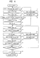
- Fig. 4 is a flowchart showing the operational sequence in the present embodiment.
- each of the discharging port surfaces 22a, 22b, 22c, and 22d of the printing heads 2a, 2b, 2c, and 2d is capped by the capping means 20.
- a printing signal is inputted into the control circuit 16
- a pressurized ink circulation is started (step S1).
- the head cleaning is executed simultaneously (step S2).
- step S3 and step S4 when the head cleaning and the pressurized ink circulation are terminated, the residual liquid droplets and others on the discharging surface of the discharging head are removed (step S5) by the application of the air stream cleaning. Then, the head cap is released (step S6).
- the cleaning member 70 is cleaned (step S7).
- the exceedingly viscous ink, foreign particles, and others adhering to the cleaning member 70 are washed away together with the rinsing liquid.
- part of the ink is in a condition that it flows out from the discharging surface of the nozzles by the pressurized ink circulation. Therefore, it is possible to prevent the rinsing liquid from flowing into the liquid chamber side in the head from the nozzle discharging surface.
- the rinsing liquid is sucked so that the residual rinsing liquid in the cleaning member 70 is appropriately reduced, and its capability to collect ink, foreign particles, and others is enhanced thereby to increase the cleaning efficiency of the cleaning member 70. Also, the rinsing liquid being sucked and exhausted, there occurs due to the capillary phenomenon the liquid absorbing force in the porous material serving as the cleaning member 70.
- the ink By making this liquid absorbing force greater than the negative pressure (meniscus formation force) given to the nozzles of the liquid discharging head, together with the synergistic effects obtainable form the high affinity of the residual rinsing liquid such as water in the cleaning member 70 and the ink in the nozzles, the ink can be in a state where it is drawn from the nozzles when the cleaning is executed. As a result, the mixture of the rinsing liquid in the liquid chamber can be prevented, hence making the prevention of the lowered ink density possible. Further, the ink absorbing capability in the nozzles also occurs. It is also possible to produce another effect that the exceedingly viscous ink in the nozzles can be removed simultaneously.
- the rinsing liquid is sucked in the step S8, and an appropriate amount of the remaining rinsing liquid in the cleaning member 70 is reduced.
- a cleaning member a continuously porous material having a vacancy ratio of 70 to 85%: Commercial name: RUBYCELLCLEAN - Toyo Hygienic Material, Inc.
- a water is contained in a cleaning member (a continuously porous material having a vacancy ratio of 70 to 85%: Commercial name: RUBYCELLCLEAN - Toyo Hygienic Material, Inc.) substantially in the same volume as this material before suction, and an approximately 50% of the foregoing volume of water is absorbed and exhausted from the cleaning material, for example, it is found that the water which contacts this cleaning member after that is again absorbed in 30 seconds up to an approximately 80% of the volume of the water which has been exhausted.
- the cleaning member it is preferable to use a three dimensional net material or a continuously porous material.
- a rinsing liquid is contained substantially in the same volume as that of the cleaning member at the outset, it is possible to create a high liquid absorptivity in the cleaning member by causing it to exhaust the rinsing liquid by suction preferably in a 30% or more of such a volume, more preferably in a 40% or more, or most preferably in 50% or more.
- a driving signal is emitted from the motor driver 23 to transfer the driving force of the driving motor 5 to the carriage 1 through the belt 4.
- the carriage 1 is driven to allow the head to reciprocate (step S9).
- the cleaning member 70 wipes the discharging port surface 22 sequentially to clean it (step S10).
- the cleaning means to wipe off the rinsing liquid, ink, foreign particles, and others on the discharging port surface and clean it.
- the edge 70D of the cleaning member 70 is allowed to reach the recess of the holder, it is possible to clean the stepping parts between the holder surface 102 and the discharging port surface 22.
- each position of the printing heads 2a, 2b, 2c, and 2d is detected by the preliminary discharge position detecting sensor 35 to enable the clog prevention means 31 to discharge ink preliminarily for a given period of time (step S11).
- the ink droplets are being discharged for the image printing in a dot matrix pattern in the printing width portion P of a printing sheet 6, beginning at the printing start detecting position P 0 detected by the printing start detecting sensor 34 while this means is in travel in the direction indicated by an arrow D (step S12).
- step S7 the cleaning of the cleaning member is performed (step S13), and then, as in the foregoing step S8, the suction of the rinsing liquid is performed (step S14) to recover the cleaning capability of the cleaning member.
- the carriage 1 is driven in the direction indicated by an arrow E to return to the empty discharging position.
- the printing sheet 6 is fed by the printing width P in the direction indicated by an arrow F.
- step S15 the carriage 1 is further returned to the capping position.
- step S16 the cleaning means 50 so that the discharging port surface 22 is cleaned by the cleaning member 70.
- the cleaning member 70 is held down in the carriage traveling direction E as in the case of the forward movement.
- the discharging port surface 22 is wiped off by the wiping surface 70C for cleaning.
- step S10 the cleaning in the returning movement is performed.
- the wiping surface 70B of the cleaning member since the wiping surface 70B of the cleaning member is used in the forward movement, the wiping surface 70C which is once stained is not used to wipe off the discharging port surface 22. Thus, the cleaning effect is not only affected, but it is doubly enhanced.
- step S17 the discharging surface 22 of the head 2 is capped by the capping means 20 and closed airtightly (step S18).
- FIG. 7 is a view illustrating another embodiment.
- a reference numeral 80 designates a cleaning member which is held to a holder 81 by the fixing boards 82a and 82b which pinch the both ends of the cleaning member; and 83a and 83b, mounting screws.
- An opening 81a is provided for the holder 81.
- a flexible and resilient material can be used for the cleaning member 80. Therefore, it is possible to widen the wiping area a with respect to the head 2 by making the surface of the wiping portion 80A round.
- step S19 the cleaning by the cleaning means 50 is good enough just by the forward movement alone, it may be possible to perform the head cleaning by the cleaning member in the forward movement of the head (step S19) as indicated by a flowchart shown in Fig. 8, and then (in step S20), the cleaning member is retracted (in step S21); thus omitting any cleaning in the returning movement of the head. In this way, the printing speed can be increased as a whole.
- the cleaning by the cleaning means 50 is good enough just by the returning movement of the head, the cleaning in its forward movement can be omitted likewise; hence making it possible to increase the printing speed as a whole.
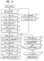
- Fig. 11 is a flowchart showing another operational sequence according to the present invention.
- the head cleaning process in the steps S3, S4, and S6 in the flowchart shown in Fig. 4 is omitted.
- steps S36 and S37 shown in Fig. 11 the advancing and returning movements of the head are conducted before the image printing, and the head cleaning is executed by the cleaning member at each time.
- the head surface is more stained (more residual ink) by the pressurized ink circulation than at the time of image printing, it is arranged in the present embodiment to wipe it once each in the advancing movement and in the returning movement. In this way, the water rinsing and air cleaning for the head are omitted.
- the wiping operation in the head returning movement is performed. This is because when the wiping operation in the head advancing movement is completed after the termination of the one scan in the main scanning direction, the carriage reaches the starting position to initiate the main scanning; thus making it possible to speed up the printing operation as a whole, leading to a shorter printing time.
- the cleaning member while a flexible porous material is used for the cleaning member, it may be possible to enhance further the cleaning effect using the conventional wiping, where a conventional rubber blade is employed as its cleaning member, by combining the rinsing means using the present cleaning member.
- a structure is disclosed where the discharging port surface of the head is cleaned by the cleaning member subsequent to the suction of the rinsing liquid of the cleaning member, it may be possible to conduct the cleaning of the head discharging port surface and the suction operation at the same time. In this way, the suction force of a pump and others is directly exerted on the discharging port surface of the printing head to enhance the resultant liquid absorptivity of the cleaning member. Therefore, this is particularly effective when the residual droplets of ink and rinsing liquid adhering to the cleaning member due to cleaning are great.
- the suction of the rinsing liquid of the cleaning member is performed by operating a suction pump
- the present invention is not limited thereto.
- Fig. 12 is a block diagram showing the fundamental structure of a ink jet printing system.
- This ink jet printing system comprises widely an image reading device 201 which reads an original image produced by a designer or the like and converts the original image into the original image data represented by electrical signals; an image processing unit 202 which fetches the original image data from the image reading device 201 to process and output them as the image data; and an image printing unit 203 which performs the printing on a textile and other printing media in accordance with the image data produced by the image processing unit 202.
- the image reading device 201 an original image is read by a CCD image sensor.
- the image processing unit 202 the data are produced from the inputted original image data to drive the ink jet printing unit A-2 (Fig.
- the image printing unit 203 the printing is performed by the ink jet printing unit A-2.
- the ink jet printing unit A-2 performs the printing by flying fine ink droplets toward the printing medium and causes the ink droplets to adhere to the printing medium.
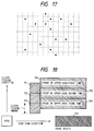
- Fig. 13 is a view schematically showing the outline of an image printing unit particularly suitable for a liquid discharging apparatus according to the present invention.
- image printing unit particularly suitable for a liquid discharging apparatus according to the present invention.
- any description of the cleaning of the liquid discharging ports of the liquid discharging head will be omitted.
- the main unit A further comprises a feeding unit A-1 to precisely feed the textile including a platen, and an ink jet printing unit A-2.
- a rolled textile 236 which is preparatorily processed is being fed by the supply unit B to the main unit.
- a thin endless belt 237 which is precisely step driven is tensioned around a driving roller 247 and a winding roller 249.
- the driving roller 247 is directly step driven by a high resolution stepping motor (not shown) to step feed the belt by that stepping amount.
- the cloth 236 thus fed is pressed and tensioned by a pressing roller 240 onto the surface of the belt 237 which is backed up by the winding roller 249.
- the cloth 236 thus step fed by the belt is positioned in a fixed position by a platen 232 arranged on the back side of the belt in a first printing unit 231 and is printed by the ink jet head 209 from its surface side.
- a heating plate 234 from the back side of the belt and is dried from the surface by a hot air which is supplied from and exhausted to a hot air duct 235.
- a superposed printing is performed in the same manner as in the first printing unit.
- the drying section may be a given space for drying ink naturally instead of any forced drafting means while the printing medium is being transferred from the first ink jet printing unit to the second ink jet printing unit.
- the printed textile is torn and again dried in a rear drying unit 246 arranged in the same manner as in the foregoing hot plate and hot air duct.
- the printed textile is guided to a guide roller 241 and wound by a winding roller 248.
- the rolled textile is removed from the apparatus and finished to a final product in a batch process through an additional process including coloring, rinsing, and drying.
- the preferred embodiment is such that information is printed by the head of the first printing unit after thinning the dot numbers, and that after the drying process, the ink droplets are discharged by the head of the second printing unit to complement the information which has been thinned in the first printing unit.
- Fig. 14 the textile 236 which a printing medium is tensioned on the belt and step fed upward in Fig. 14.
- the first printing unit 231 shown in the lower part of Fig. 14 there is a first carriage 244 having eight ink jet heads for special colors S1 to S4 in addition to the Y, M, C, and Bk.
- the ink jet heads (printing heads) according to the present embodiment use those having the elements which generate thermal energy to give the film boiling to ink as the energy utilized for discharging the ink, and also having 128 discharging ports arranged in a density of 400 dpi (dots/inch).
- a drying unit 245 comprising a hot plate 234 which gives heat from the back side of the belt and a hot air duct 235 which give a hot air from the surface for drying.
- the heat transmission surface of the hot plate 234 is pressed onto a strongly tensioned endless belt 237 to heat this conveyer belt 237 from its back side intensively with a high temperature high-pressure steam which is provided in a hollow inner side.
- the conveyer belt 237 directly heats the textile 236 tensioned on it effectively by the thermal conduction.
- heat collecting fins 234' are arranged to concentrate heat onto the back side of the belt efficiently.
- the side which is not in contact with the belt is covered with a heat isolation material 243 to prevent any heat loss.
- a dry hot air is blown from a supply duct 230 arranged on the downstream for the enhancement of the drying effect obtainable by blowing an air having a lower moisture onto the drying textile. Then, the air streaming in the direction opposite to the conveying direction of the textile while containing a sufficient moisture is sucked by a suction duct 233 arranged on the upstream side by a force which enables the air to be sucked in a quantity much greater than that of the blowing. In this way, a caution is taken so as not to give any dew drops to the surrounding equipment due to the leakage of evaporated moisture.
- the supply source of the hot air is arranged in the back side in Fig. 14, and the suction is conducted from the front side.
- the pressure difference between the blowing outlet 238 and suction inlet 239 facing the textile is arranged to be even over the entire area in the longitudinal direction.
- the air blowing and sucking sections are offset toward the downstream side with respect to the center line of the hot plate arranged on the back side so that the air can be blown onto the place which is sufficiently heated. In this way, it is possible for the first printing unit 231 to intensively dry a good amount of water contained in the ink including a thinning agent, which the textile has received in the first printing.
- the second printing unit 231' In the downstream thereof (upward), the second printing unit 231' is arranged.
- the second printing unit comprises a second carriage 244' having the same structure as the first carriage.
- the superposed printing is performed using the first printing unit 231 and the second printing unit 231'.
- the description will be made of the superposed printing in detail.
- Fig. 15 is a view illustrating a printed data made by a sequential multi-scanning for a superposed printing.
- each rectangular area surrounded by dotted lines corresponds to one dot (pixel).
- the area of each rectangle is approximately (63.5 ⁇ m) 2 .
- Those represented by small black circles are where the dots are impacted.
- Those where no small black circles are present are where no printing is conducted.
- the ink jet head is shifted in the direction indicated by an arrow F and the ink is discharged from the ink discharging nozzles in a given timing. This sequential multi-scanning is executed to correct the unevenness among each of the nozzles due to the uneven size of the ink droplets discharged from each of the nozzles and the unevenness existing in the ink discharging directions.
- the printing is executed by a plurality of nozzles on one and the same line (the direction in which the head is shifted). In this way, one line is formed by a plurality of nozzles and the randomicity of the nozzle characteristics of each of the ink jet heads is utilized; thus implementing the reduction of the density unevenness.
- a sequential multi-scanning is executed by a two-time scanning, the printing is performed using the upper half of the ink jet head for the first scanning, and again the printing is performed using the lower half of the ink jet head for the second scanning.
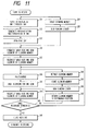
- Fig. 16 and Fig. 17 are views showing the printed example by this sequential multi-scanning.
- the data shown in Fig. 15 are printed, for example, only the printing data of odd numbers of the data created in the shifting direction of the ink jet head as shown in Fig. 16 are printed by the upper half of the ink jet head. Then, the ink jet head (carriage) is returned to in the direction of its home position, and the cloth 236 is fed in an amount equivalent to a half of the width of the ink jet head. Then, as shown in Fig. 17, the dots of even numbers in the shifting direction of the ink jet head are printed using the lower half of the nozzles of the ink jet head. In this way, the data shown in Fig. 15 are printed on the cloth 236 by the two-time scanning.
- Fig. 18 shows an printing example made by a usual two-time multi-scanning.
- the areas printed by the ink jet head of a first printing unit 231 are represented by reference marks and numerals, (down first) 701, (down second) 702, and (down third) 703, respectively; and the areas printed by the ink jet head of a second printing unit 231', (up first) 704, (up second) 705, and (up third) 706, respectively.
- the cloth feeding direction is as indicated by an arrow.
- the step feeding amount of the cloth 236 at a time corresponds to the printing width of the ink jet head.
- all of the printing areas are printed by the use of either the upper half of the ink jet head of the second printing unit 231' and the lower half of the ink jet head of the first printing unit 231 or the lower half of the ink jet head of the second printing unit 231' and the upper half of the first printing unit 231.
- the data which are printed by each of the ink jet heads are thinned as shown in the foregoing Fig. 16 and Fig. 17, and as a result of the superposed printing by these two ink jet heads, the printing density is obtained as shown at 707.
- the textile is dried (including the natural dry).
- the dyestuff on textile fabric is dispersed, and a process is executed to cause the dyestuff to be reactively fixed to the fabric. With this process, it is possible for the printed textile to obtain a sufficient coloring capability and strength because of the dyestuff fixation.
- a steaming method is named, for example.
- the textile having an in receptacle layer is disclosed in Japanese Patent Laid-Open Application No. 62-53492, for example.
- the textile which contains reduction preventive agents or alkaline substances there are proposed the textile which contains reduction preventive agents or alkaline substances.
- alkaline substance there can be named, for example, hydroxide alkali metals such as sodium hydroxide, potassium hydroxide; mono-, di-, and tori-ethanol amine, and other amines; and carbonate or hydrogen carbonate alkali metallic salt such as sodium carbonate, potassium carbonate, and sodium hydrogen carbonate.
- organic acid metallic salt such as calcium carbonate, barium carbonate or ammonia and ammonia compounds.
- sodium trichloroacetic acid and the like which become an alkaline substance by steaming and hot air treatment.
- the alkaline substance which is particularly suitable for the purpose there are the sodium carbonate and sodium hydrogen carbonate which are used for dye coloring of the reactive dyestuffs.
- starchy substances such as corn and wheat
- cellulose substances such as carboxyl methyl cellulose, methyl cellulose, hydroxy ethel cellulose
- polysaccharide such as sodium alginic acid, gum arabic, locasweet bean gum, tragacanth gum, guar gum, and tamarind seed
- protein substances such as gelatin and casein
- natural water soluble polymer such as tannin and lignin.
- polysaccharide polymer and cellulose polymer should be preferable.
- a water soluble metallic salt there can be named the pH4 to 10 compounds which produce typical ionic crystals, namely, halogenoid compounds of alkaline metals or alkaline earth metals, for example.
- NaCl, Na 2 SO 4 , KCl and CH 3 COONa and the like can be named for the alkaline metals, for example.
- CaCl 2 , MgCl 2 , and the like can be named for the alkaline earth metals.
- salt such as Na, K and Ca should be preferable.
- a method is not necessarily confined in order to enable the above-mentioned substances and others to be contained in the textile.
- a dipping method, padding method, coating method, spraying method, and others can be used.
- a reactive fixation process such as this can be a method publicly known in the art. There can be named a steaming method, HT steaming method, and thermofixing method, for example. Also, alkaline pad steaming method, alkaline blotch steaming method, alkaline shock method, alkaline cold fixing method, and the like can be named when a textile is used without any alkaline treatment given in advance.
- the removal of the non-reactive dyestuff and the substances used in the preparatory process can be conducted by a rinsing method which is publicly known subsequent to the above-mentioned reactive fixation process. In this respect, it is preferable to conduct a conventional fixing treatment together when this rinsing is conducted.
- the printed textile is cut in desired sizes after the execution of the above-mentioned post process. Then, to the cut off pieces, the final process such as stitching, adhesion, and deposition is executed for the provision of the finished products.
- the final process such as stitching, adhesion, and deposition is executed for the provision of the finished products.
- one-pieces, dresses, neckties, swimsuits, aprons, scarves, and the like, and bed covers, sofa covers, handkerchiefs, curtains, book covers, room shoes, tapestries, table clothes, and the like are obtained.
- the methods to machine stitch the textile to make clothes and other daily needs are disclosed widely in publicly known publications such as "Modern Knitting and Sewing Manual” published by the Textile Journal Inc. or a monthly magazine “Souen” published by Bunnka Shuppan Kyoku, and others.
- the present invention produces an excellent effect on an ink jet printing head and printing apparatus, particularly on those employing a method for utilizing thermal energy to form flying ink droplets for the printing.
- the principle is such that at least one driving signal, which provides a rapid temperature rise beyond a departure from nucleation boiling point in response to printing information, is applied to an electrothermal transducer disposed on a liquid (ink) retaining sheet or liquid passage whereby to cause the electrothermal transducer to generate thermal energy to produce film boiling on the thermoactive portion of the printing head; thus effectively leading to the resultant formation of a bubble in the printing liquid (ink) one to one for each of the driving signals.
- the liquid (ink) is discharged through a discharging port to produce at least one droplet.
- the driving signal is preferably in the form of pulses because the development and contraction of the bubble can be effectuated instantaneously, and, therefore, the liquid (ink) is discharged with quicker responses.
- the driving signal in the form of pulses is preferably such as disclosed in the specifications of U.S. Patent Nos. 4,463,359 and 4,345,262.
- the conditions disclosed in the specification of U.S. Patent No. 4,313,124 regarding the rate of temperature increase of the heating surface is preferably are adopted, it is possible to perform an excellent printing in a better condition.
- the structure of the printing head may be as shown in each of the above-mentioned specifications wherein the structure is arranged to combine the discharging ports, liquid passages, and electrothermal transducers as disclosed in the above-mentioned patents (linear type liquid passage or right angle liquid passage). Besides, it may be possible to form a structure such as disclosed in the specifications of U.S. Patent Nos. 4,558,333 and 4,459,600 wherein the thermally activated portions are arranged in a curved area.
- the present invention demonstrates the above-mentioned effect more efficiently with a structure arranged either by combining plural printing heads disclosed in the above-mentioned specifications or by a single printing head integrally constructed to cover such a length.
- the present invention is effectively applicable to a replaceable chip type printing head which is connected electrically with the main apparatus and can be supplied with ink when it is mounted in the main assemble, or to a cartridge type printing head having an integral ink container.
- a printing mode for the printing apparatus it is not only possible to arrange a monochromatic mode mainly with black, but also it may be possible to arrange an apparatus having at least one of multi-color mode with different color ink materials and/or a full-color mode using the mixture of the colors irrespective of the printing heads which are integrally formed as one unit or as a combination of plural printing heads.
- the present invention is extremely effective for such an apparatus as this.
- the ink may be an ink material which is solidified below the room temperature but liquefied at the room temperature or may be liquid. Since the ink is controlled within the temperature not lower than 30°C and not higher than 70°C to stabilize its viscosity for the provision of the stable discharge in general, the ink may be such that it can be liquefied when the applicable printing signals are given.
- a printing apparatus there are a copying apparatus combined with reader and the like, and those adopting a mode as a facsimile apparatus having transmitting and receiving functions, besides those used as an image output terminal structured integrally or individually for an information processing apparatus such as a word processor and a computer.
- Fig. 19 is a block diagram schematically showing the structure wherein a printing apparatus according to the present invention is applied to an information processing apparatus having functions as a word processor, personal computer, facsimile, and copying apparatus.
- a reference numeral 301 designates a control unit to control the entire system, which is provided with a CPU comprising a microprocessor and others and various I/O ports to output control signals, data signals, and others to each unit or to receive control signals and data signals from each unit for controlling; 302, a displaying unit on the screen of which various menus, documentary information, image data and others read by an image reader 307 are displayed; and 303, a transparent pressure sensitive touch panel arranged on the display unit 302, which allows the item input and coordinate position input to be made on the display unit 302 by depressing its surface by a finger or the like.
- a reference numeral 304 designates an FM (Frequency Modulation) sound generating unit wherein the musical information produced by a music editor or the like is stored in its memory 310 or in an external storage unit 312 as digital data, and then, an FM operation is executed.
- the electrical signals from the FM sound generating unit 304 are transduced into audible sounds through a speaker unit 305.
- a printing unit 306 serves as an output terminal for a word processor, personal computer, facsimile apparatus, and copying apparatus, to which a printing apparatus according to the present invention is applied.
- a reference numeral 307 designates an image reading unit to photoelectrically read data on a source document for input, which is arranged on the way of the feeding passage for the source document to read a facsimile original, copying original, and other various source documents;
- 308, a facsimile transmitting and receiving unit whereby to transmit by facsimile the original data read by the image reading unit 307 or demodulate the facsimile signals received, and has an interface with the external units;
- 309 a telephone unit having various telephoning functions such as serving as an ordinary telephone or a special telephone to take messages automatically;
- storage unit including ROMs to store a system program, manager program, other application programs, fonts, dictionaries, and the like, RAMs to store the application program and text information loaded from an external storage unit 312, Video RAM, and others.
- a reference numeral 311 designates a keyboard unit to input documentary information, various commands, and the like; 312, an external storage unit having a floppy disk and hard disk as its storing media. In this external storage unit 312, text information, music, or sound information, user's application programs are stored.
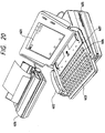
- Fig. 20 is an external view of an information processing apparatus shown in Fig. 19.
- a reference numeral 401 designates a flat panel display utilizing a liquid crystal display to display various menus, graphic information, documentary information, and the like.
- a touch panel is provided, and by depressing the surface of the touch panel by a finger or the like, it is possible to input coordinates and items specifically.
- a reference numeral 402 designates a hand set useable when the apparatus functions as a telephone.
- the keyboard 403 is detachably connected to the apparatus through a cord to enable various text information and various data to be inputted. Also, for this keyboard 403, various functional keys 404 and the like are provided.
- a reference numeral 405 designates is an inlet for a floppy disk.
- a reference numeral 407 designates a sheet stacking unit to stack the source documents read by the image reading unit 307, and the source documents thus read are exhausted from the rear part of the apparatus. Also, in a case of the facsimile transmission and reception, the required printing is executed by an ink jet printer 407.
- a CRT may be employed for the above-mentioned display 401, but it is preferable to use a flat panel such as a liquid crystal display utilizing a ferroelectric liquid crystal. With this, it is possible to make the apparatus small, think, and light.
- the above-mentioned information processing apparatus functions as a personal computer or word processor, the various kinds of information which are inputted through the keyboard unit 311 in Fig. 20 are processed in the control unit 301 in accordance with a given program, and are output to the printing unit 306 as images.
- the apparatus When the apparatus functions as a facsimile receiver, the facsimile information which is inputted from the facsimile transmitting and receiving unit 308 through a communication line are received and processed by the control unit 301 in accordance with a given program and is output to the printing unit 306 as the image of the signal thus received.
- the apparatus functions as a copying apparatus
- the source document is read by the image reading unit 307, and the data on the source document thus read are output to the printing unit 306 as the copying image through the control unit 301.
- the apparatus functions as the transmitter for the facsimile apparatus
- the original data read by the image reading unit 307 are processed for transmission by the control unit 301 in accordance with a given program, and then, the data are transmitted to a communication line through the facsimile transmitting and receiving unit 308.
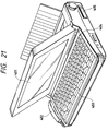
- the above-mentioned information processing apparatus may incorporate an ink jet printer in its main body as shown in Fig. 21 as an integrated type. In this case, the portability of the apparatus can be further enhanced.
- the corresponding reference marks are provided for the parts having the same functions as those appearing in Fig. 20.
Abstract
Description
- The present invention relates to a liquid discharging apparatus using a liquid discharging head to discharge ink and other liquids and a printing method using such an apparatus. More particularly, the invention relates to a printing apparatus and a printing method whereby to perform a given printing for a paper, cloth, unwoven cloth, OHP sheet, and other printing media. Furthermore, the present invention is effectively applicable to the provision of a printing apparatus capable of continuously printing a cloth having a printing width of one meter or more for a long period of time. The present invention is applicable to various office equipment and mass-processing equipment such as printers, copying machines, facsimile apparatuses, and word processors.
- As a conventional liquid discharging apparatus, there is the apparatus which performs the printing by discharging a liquid or utilizes a special liquid by discharging it. In general, the discharging head which discharges a liquid is extremely small. Thus, the dyestuff or pigment mixed in a liquid solidifies or foreign particles adhering to the head block the liquid to be discharged, leading to the defective printing of the printing apparatus, a problem that the discharging liquid cannot be utilized efficiently. Usually, therefore, suction, pressurization, known as recovery means, is provided which is operated at appropriate intervals in order to cause the liquid to be forcibly exhausted, the discharging area in the discharging ports to be cleaned, or to eject air or liquid to the discharging area in the discharging ports for cleaning.
- Nevertheless, while it is effective to dissolve and remove the exceedingly viscous ink or fixed substances in the discharging ports by ejecting a liquid to the discharging ports by such a recovery means as described above thereby to wash away the adhesive substances with the liquid, this method tends to create a problem that the printing density is lowered because the rinsing liquid is mixed with ink in the discharging nozzles the inside of which are negatively pressurized at that time, and causes the ink density to be reduced.
- Also, with the recovery means which does not use any rinsing liquid, the exceedingly viscous ink adheres to the vicinity of the nozzles of the discharging head, thus tending to create clogging or the disabled ink discharging.
- Also, in a case where the liquid is forcibly exhausted from the discharging ports by suction, there is a need for making the inner volume of the cap great in order to airtightly close the discharging head when it is sucked if the employed discharging head uses many numbers of discharging nozzles, and it becomes difficult to provide a given control in a negative pressure accordingly.
- Also, for a method using only a sponge to be in contact with the discharging head for cleaning, there is a possibility that foreign particles are pressed into the nozzles to result in the disabled discharging if the employed discharging head is such as having fine nozzles of a 400-dpi resolution. Also, if this type of sponge is sufficiently wet, the liquid in the sponge is sucked into the nozzles due to the negative pressure in the nozzles to cause the ink density to be reduced, hence creating the problem that the printing density is lowered.
- Further, in order to prevent the spray of liquid from being accumulated on the head surface at the time of ink discharging to clog the discharging ports, it is conceivable that the head surface should be wiped off by a resilient rubber blade, but when an operation must be continued for long hours to meet an industrial requirement, there is a possibility that the wiped-off ink is accumulated without any particular place to dispose of it and becomes an exceedingly viscous ink. Thus, the discharging head is rubbed by a blade to which such an exceedingly viscous ink adheres, and in such a case, the disabled discharging is invited instead after all Particularly, when a colour printing apparatus is used, the spray is collected from its four heads, the problem of extraneous liquid is more in evidence.
- The present invention is designed to solve the above-mentioned problems. It is an object of the invention to provide a liquid discharging apparatus and a printing method using such an apparatus capable of enhancing the cleaning effect for the liquid discharging ports of the liquid discharging head of the apparatus so that a stable liquid discharging is possible for a long time.
- EP-A-0,446,885 discloses an ink jet recording apparatus for discharging ink to perform recording comprising a carriage member for mounting recording means for discharging ink, a cleaning member arranged to face the regions other than the region for the aforesaid recording means to clean the discharging port formation face of the aforesaid recording means, transporting means for transporting the aforesaid cleaning member to a position to clean recording means and a position not to clean it, and driving means for relatively driving the aforesaid carriage member and transporting means for the aforesaid cleaning member to clean the aforesaid discharging port formation face. The aforesaid cleaning member is provided with a first cleaning member (2a) mainly used for cleaning the discharging port formation portion of the aforesaid recording means and a second cleaning member (2b) mainly used for cleaning the circumference of the aforesaid discharging port formation portion. Hence, the ink discharging condition is maintained and recovered to effectuate a high-quality recording reliably.
- US-A-4,296,418 discloses an ink jet printing apparatus in which an ink clog is automatically sensed in an ink ejection nozzle. The clog is cleared by moving a cap into covering engagement with the nozzle orifice, causing solvent to flow trough the nozzle from the cap to dissolve the clogged ink and subsequently causing air to flow through the cap and nozzle to purge solvent therefrom.
- According to the invention there is provided a recording apparatus for use with a liquid discharging head for discharging recording liquid, and comprising: a cleaning member capable of holding a rinsing liquid to clean the liquid discharging ports of said liquid discharging head; characterised by rinsing liquid supplying means for supplying a rinsing liquid to said cleaning member; and rinsing liquid exhausting means to enable at least part of any rinsing liquid present in the cleaning member to be exhausted and to create a liquid absorptive force in said cleaning member.
- Further, according to the invention there is provided a method for printing by use of a liquid discharging head which prints by discharging a recording liquid onto a printing medium, comprising the steps of: providing a cleaning member capable of holding a rinsing liquid to clean the liquid discharging ports of said liquid discharging head; supplying a rinsing liquid to said cleaning member; exhausting part of the rinsing liquid in the cleaning member to cause said cleaning member to create a liquid absorptive force; bringing said cleaning member and the liquid discharging ports of said liquid discharging head into abutting relationship when the rinsing liquid is held in said cleaning member and the liquid absorptive force is created in said cleaning member; parting said cleaning member and the liquid discharging ports of said liquid discharging head; and printing by discharging recording liquid from said liquid discharging head onto a printing medium.
- By means of the present invention, it is possible to maintain the liquid discharging ports of the liquid discharging head always in a cleaned condition so that the liquid discharging is stabilized for a long period of time.
- Hence, it becomes possible to implement a stable recovery even in a case where the liquid is highly viscous, a high density nozzle is employed, and an industrial printing is performed for a long time under severe conditions.
- Also, it is possible to obtain a higher cleaning effect by adopting a flexible porous material for wiping means together with the cleaning by use of a rinsing liquid as well as the suction of the rinsing liquid. Also, it is possible to prevent the printing density from being lowered by applying the present invention to a printing apparatus because the ingression of the rinsing liquid into the nozzle unit of the head can be prevented by cleaning the head while ink or other liquids are being circulated under pressure.
- As printing media, textiles, wall papers, wall clothes, paper sheets, OHP films can be named among others.
- Here, in the specification hereof, the textiles include woven cloth, unwoven cloth, and clothes and nets irrespective of materials.
- Also, the above-mentioned wall papers include the adhesive materials used for covering the walls using paper, textile, synthetic resin sheet as its material.
- In the specification hereof, the term "printing" is meant to include a "textile printing" and a "recording", and it does not confine the purpose of the printing in any sense. It widely includes providing printing media with images.
- In the present invention, it may be possible to arrange a liquid discharging head which discharges a bleaching agent to decolor ink, for example, in addition to the liquid discharging head to discharge ink to a printing medium. This is used to locally bleach the part which is deeply dyed by ink.
- Further, it may be possible to arrange a liquid discharging head to discharge an interfacial active agent for processing clothes, protecting the surface of textiles, or to discharge a coating agent to coat the surface of textiles in order to prevent ink from adhering locally thereto.
-
- Fig. 1 is a view illustrating cleaning means observed in the main scanning direction of a head.
- Fig. 2 is a view illustrating a cleaning member and a head observed from above.
- Fig. 3 is a view illustrating the operation of an ink jet printing apparatus.
- Fig. 4 is a flowchart showing the operational sequence in the present embodiment.
- Fig. 5 is a perspective view showing the relation between a cleaning member and a head.
- Fig. 6 is a perspective view showing the relation between a cleaning member and a head.
- Fig. 7 is a view showing another example of the cleaning member.
- Fig. 8 is a flowchart showing another example of the operational sequence in the present embodiment.
- Fig. 9 is a view showing an example in a case where a liquid discharging apparatus according to the present invention is applied to a serial type ink jet printing apparatus.
- Fig. 10 is a view showing the structural example of a liquid discharging head.
- Fig. 11 is a flowchart showing another example of the operational sequence in the present embodiment.
- Fig. 12 is a view showing the fundamental structure of an ink jet printing system from a step to read images and to a step to print them.
- Fig. 13 is a cross-sectional view showing the structure of an image printing unit.
- Fig. 14 is a perspective view showing the structure of an image printing unit.
- Fig. 15 is a view illustrating a printing by use of a sequential multi-scan.
- Fig. 16 is a view illustrating a printing by use of a sequential multi-scan.
- Fig. 17 is a view illustrating a printing by use of a sequential multi-scan.
- Fig. 18 is a view illustrating a printing by use of a sequential multi-scan.
- Fig. 19 is a block diagram schematically showing the structure of an information processing apparatus.
- Fig. 20 is an external view showing the information processing apparatus shown in Fig. 19.
- Fig. 21 is an external view showing another example of the information processing apparatus.
- Hereinafter, the present invention will be described in accordance with the accompanying drawings.
- Fig. 3 and Fig. 9 are views illustrating an example wherein a liquid discharging apparatus according to the present invention is applied to a serial type ink jet printing apparatus.
- In Fig. 3 and Fig. 9, a
carriage 1 mounts on itcolor printing heads guide shaft 3 supports and guides thecarriage 1 movably.Reference numerals - A belt 4 which is an endless belt is partially connected to the
carriage 1. Thecarriage 1 is driven by adriving motor 5 which is a pulse motor driven by amotor driver 23. Thus, the carriage is moved on theguide shaft 3 through the belt 4 along the printing surface of aprinting sheet 6. Further, there are provided afeed roller 7 to feed aprinting sheet 6, guiderollers printing sheet 6, and a printingsheet feed motor 9. - Also, for each of the printing heads 2a, 2b, 2c, and 2d, a
liquid passage 10 is arranged to discharge ink toward theprinting sheet 6. To thepassage 10, ink is supplied from each of theink tanks supply tubes passages 10, ink discharging signals are selectively supplied from each of thehead drivers - Further, for each of the printing heads 2a, 2b, 2c, and 2d,
head heaters 14a, 14b, 14c, and 14d (14b, 14c, and 15d are not shown) andtemperature detecting means 15a, 15b, 15c, and 15d (15b, 15c, and 15d are not shown) are provided, respectively. The detected signals from thetemperature detecting means 15a, 15b, 15c, and 15d are inputted into acontrol circuit 16 having a CPU. Thecontrol circuit 16 controls the heating in thehead heaters 14a, 14b, 14c, and 14d on the basis of these signals through adriver 17 and apower source 18. - Capping means 20 are butted to the discharging port surface of each of the printing heads 2a, 2b, 2c, and 2d when the printing is at rest. The printing heads 2a, 2b, 2c, and 2d are shifted to a position opposite to the capping means 20 when the printing is at rest. Then, the capping means 20 is driven forward by means of a
cap driver 25 to perform the capping by allowing aresilient member 44 to but the discharging port surface. - If the printing head is left intact in the air for a long time, the ink in the nozzles are evaporated to make it exceedingly viscous, leading to an unstable discharging. In order to prevent this, the nozzle unit is sealed from the atmosphere and airtightly enclosed (capped) when the printing is at rest. In the cap, a liquid absorbent kept sufficiently wet by ink is provided to suppress the increase of the ink viscosity as much as possible by maintaining the inside of the cap highly moisturized.
- To the capping means 20, an
electromagnetic valve 61 for water discharging and anair pump driver 62 are connected. The rinse water discharging nozzle and the air ejection nozzle arranged in the capping means 20 are driven under the control of acontrol circuit 16, respectively. Also, the ink, foreign particles, and others adhering to or fixed to the head surface are cleaned by the liquid flow and air stream ejected from each of the nozzles. - In this respect, the above-mentioned flow of the ejected liquid eases the state of the fixed particles and removes them or cause them to be in a removable condition. This is effectively applicable to the minute parts. Also, the above-mentioned ejected air stream removes from the head surface the remaining liquid itself after its ejection, thus making it possible to implement the promotion of the recovery action for the particles in the removable state as well as the liquid. From the nozzle arranged in the upper part of the flow ejection cap, the air stream is blown toward the surface of the nozzles to blow the particles and liquid down to the lower part of the printing head.
- Also, when the ink is left intact for a long period of time in the head being capped, a recovery is also conducted by pressurizing the ink. In other words, if the ink is left intact for a long period of time, the ink in the nozzles is being evaporated gradually even if the head is capped and it becomes exceedingly viscous. Also, air bubbles remain in the nozzles occasionally to hinder a stabilized discharging in some cases. Therefore, when a printing is started, a pump arranged in the ink tank is driven to pressurize the ink to cause any exceedingly viscous ink and residual air bubbles in the nozzles to be exhausted outside the nozzles. This is also effective in washed away the dust particles or fluffs adhering to the nozzle surface or the dust particles which may be present in the nozzles for the maintenance of a stabilized discharging.
- Clogging prevention means 31 receives the discharged ink when the printing heads 2a, 2b, 2c, and 2d perform its preliminary discharging operation. The clogging prevention means 31 is arranged to face the printing heads 2a, 2b, 2c, and 2d, and is provided with a
liquid receiving member 32 as a liquid receptacle to absorb the ink which is preliminarily discharged. This means is arranged between the capping means 20 and a position to start the printing. In this respect, for the materials of theliquid receiving member 32 and aliquid holding member 45, it is effective to adopt a spongy porous material or sintered plastic among others. - Here, the preliminary discharge is an ink discharging without any particular purpose of printing itself. This discharge is conducted to assure the temperature of the area the temperature of which is lowered due to the ejected liquid flow and ejected air stream as well as to remove any unwanted particles in the discharging ports. Also, besides this, given driving pulses are provided before the printing is started to cause the ink to be discharged from the entire nozzles towards the capping unit and others (aging operation) or in some cases, this is performed while in the capping state if it is desired to enhance the wetting condition of the atmosphere surrounding the nozzles.
- To the cleaning means 50, an
electromagnetic valve 51 for rinsing and asuction pump driver 52 are connected, and perform under control of thecontrol circuit 16 the discharge of rinsing liquid from rinsing means 53, and the suction of rinsing liquid form the cleaning means 50, respectively. As the rinsing liquid, water is used, for example. - Fig. 10 shows the structural example of a liquid discharging head. A
reference numeral 2 designates a discharging head; 22, its discharging port surface; 101B, the nozzle unit in which a plurality of liquid passages are arranged in parallel in the vertical direction, and the discharging energy generating elements such as electrothermal transducers are provided; and 101C, an ink chamber to share the ink supply to each of the liquid passages, which connects them with anink tank 110 throughsupply tubes supply tube 104, agear pump 105 is provided to pressurize the ink in the ink supply system to theprinting head 2 and cause the ink to be exhausted from the discharging ports when the air bubbles and particles mixed in the supply passages or in thenozzle unit 101B are removed or a discharge recovery process such as the removal of the exceedingly viscous ink, and the like is performed. - Fig. 1 and Fig. 2 show the structural example of the cleaning means 50. Fig. 1 is a view illustrating the cleaning means 50 observed in the main scanning direction of the
head 2. Fig. 2 is a view illustrating a cleaningmember 70 and ahead 2 observed from above. The cleaningmember 70 is a flexible body having a three dimensional net structure, for example, is made of a continuously porous material. As the material for the cleaning member, a high molecular porous material is preferably usable. When a high molecular porous material is used, it is preferable to use the one which does not change its volume even when it absorbs ink but not the one which changes its volume remarkably by absorbing ink mists such as a high molecular foaming material. As a suitable one, a material of a foaming formal resin type is preferably named. Also, it may be possible to use materials having the three dimensional net structure other than the porous materials described above. - Also, as a cleaning member used here, it is possible to utilize a high molecular porous material of a sintered type. For example, it is possible to name a low density polyethylene, high density polyethylene, high molecular polyethylene, compound polyethylene, polypropylene, polymethyl methacrylilate, polystyrene, acrylonitrile copolymer, ethylene-vinyl acetate copolymer, flouric resin, phenol resin, and other thermally sintered materials. Particularly in consideration of the ink mist absorptivity and ink resistivity, it is preferable to employ those using a low density polyethylene, high density polyethylene, high molecular polyethylene, or polypropylene.
- Particularly, a continuously pored ultrafine material using urethane as its material (Commercial name: RUBYCELLCLEAN - Toyo Hygienic Material, Inc.) is suitably used among them.
- Now, a
reference numeral 71 designates a holder to clamp and fix the cleaningmember 70 by means of a fixingboard 72, and fixing screws 73. For theholder 71, anopening 71B is arranged on thesurface 71A which butts the cleaningmember 70, and is connected to asuction tube 74 through aconductive passage 71C. Thus, the structure is arranged to exhaust the rinsing liquid and ink contained in the cleaningmember 70 by the sucking means 82 comprising a pump in the direction indicated by an arrow A. For this sucking means 82, it may be possible to adopt an exhausting means which is arranged in such a manner that a porous material or a fabric material is connected to the cleaningmember 70 to form a passage for the disposal of the rinsing liquid exhausted from the cleaning member. - After the rinsing by means of this suction of the rinsing liquid, the suction capability of the cleaning
member 70 against the ink and foreign particles is restored due to the appropriately reduced amount of the rinsing liquid, hence making it possible to enhance the cleaning effect for the dischargingsurface 22 of thehead 2. Also, theleading end 71A of the cleaningmember 70 is overlapped with the dischargingsurface 22 of the discharginghead 2 by a length indicated by ℓ. Therefore, when thehead 2 is in a scanning operation, the dischargingsurface 22 of thehead 2 is wiped by this overlapping portion thus arranged. - A
reference numeral 75 designates a nozzle to supply the rinsing liquid. The rinsingliquid 81 is supplied in the direction indicated by an arrow B from atank 80 serving as a rinsing liquid supply means through a rinsingliquid supply tube 76 as anelectromagnetic valve 79 opens or is closed, and further supplied downward to the cleaningmember 70 from the dischargingport 75A of the nozzle. In this way, the cleaning arrangement is made. - A
reference numeral 77 designates a receptacle container arranged below the cleaningmember 70 to receive the droplets of the rinsing liquid which are not absorbed by the cleaningmember 70 when the rinsing liquid is discharged from thesupply nozzle 75, and the ink and foreign particles adhering to the cleaningmember 70 which also drop together with the droplets of the rinsing liquid; and 78, an exhaust tube to exhaust the rinsing liquid received by thereceptacle container 77 to an exhaust unit (not shown) in the direction indicated by an arrow C. - Now, hereinafter, the description will be made of the operation of an ink jet printing apparatus. In Fig. 3, a printing
start detecting sensor 34 and a capping means detectingsensor 36 detect respectively that each of the printing heads 2a, 2b, 2c, and 2d is in a given capping position. A preliminarydischarge position sensor 35 detects the fiducial position for the preliminary discharging operation to be performed by the printing heads 2a, 2b, 2c, and 2d while being shifted in the scanning direction. - Fig. 4 is a flowchart showing the operational sequence in the present embodiment. At first, while in a standby state, each of the discharging
port surfaces control circuit 16, a pressurized ink circulation is started (step S1). In order to enhance the recovery effect by the pressurized ink circulation, the head cleaning is executed simultaneously (step S2). In step S3 and step S4, when the head cleaning and the pressurized ink circulation are terminated, the residual liquid droplets and others on the discharging surface of the discharging head are removed (step S5) by the application of the air stream cleaning. Then, the head cap is released (step S6). - Together with the recovery by means of the pressurized ink circulation, the cleaning
member 70 is cleaned (step S7). By this cleaning, the exceedingly viscous ink, foreign particles, and others adhering to the cleaningmember 70 are washed away together with the rinsing liquid. Also, part of the ink is in a condition that it flows out from the discharging surface of the nozzles by the pressurized ink circulation. Therefore, it is possible to prevent the rinsing liquid from flowing into the liquid chamber side in the head from the nozzle discharging surface. Thus, there is no resultant reduction of the ink density in the liquid chamber due to the mixture of the rinsing liquid when a printing is executed after the head cleaning; hence preventing disadvantages such as a lowered printing density. - Then, in the next step S8, the rinsing liquid is sucked so that the residual rinsing liquid in the cleaning
member 70 is appropriately reduced, and its capability to collect ink, foreign particles, and others is enhanced thereby to increase the cleaning efficiency of the cleaningmember 70. Also, the rinsing liquid being sucked and exhausted, there occurs due to the capillary phenomenon the liquid absorbing force in the porous material serving as the cleaningmember 70. By making this liquid absorbing force greater than the negative pressure (meniscus formation force) given to the nozzles of the liquid discharging head, together with the synergistic effects obtainable form the high affinity of the residual rinsing liquid such as water in the cleaningmember 70 and the ink in the nozzles, the ink can be in a state where it is drawn from the nozzles when the cleaning is executed. As a result, the mixture of the rinsing liquid in the liquid chamber can be prevented, hence making the prevention of the lowered ink density possible. Further, the ink absorbing capability in the nozzles also occurs. It is also possible to produce another effect that the exceedingly viscous ink in the nozzles can be removed simultaneously. - As described above, the rinsing liquid is sucked in the step S8, and an appropriate amount of the remaining rinsing liquid in the cleaning
member 70 is reduced. According to an experiment, when a water is contained in a cleaning member (a continuously porous material having a vacancy ratio of 70 to 85%: Commercial name: RUBYCELLCLEAN - Toyo Hygienic Material, Inc.) substantially in the same volume as this material before suction, and an approximately 50% of the foregoing volume of water is absorbed and exhausted from the cleaning material, for example, it is found that the water which contacts this cleaning member after that is again absorbed in 30 seconds up to an approximately 80% of the volume of the water which has been exhausted. - As the cleaning member, it is preferable to use a three dimensional net material or a continuously porous material. In a case where a rinsing liquid is contained substantially in the same volume as that of the cleaning member at the outset, it is possible to create a high liquid absorptivity in the cleaning member by causing it to exhaust the rinsing liquid by suction preferably in a 30% or more of such a volume, more preferably in a 40% or more, or most preferably in 50% or more.
- Now, subsequently, a driving signal is emitted from the
motor driver 23 to transfer the driving force of the drivingmotor 5 to thecarriage 1 through the belt 4. Thus, thecarriage 1 is driven to allow the head to reciprocate (step S9). Then, as shown in Fig. 5, when thecarriage 1 passes the cleaning means 50, the cleaningmember 70 wipes the dischargingport surface 22 sequentially to clean it (step S10). In this respect, according to the present embodiment, the cleaning means to wipe off the rinsing liquid, ink, foreign particles, and others on the discharging port surface and clean it. As shown in Fig. 5, when the discharging port surface is wiped off by the cleaningmember 70, the cleaning member being flexible is held down in the same direction as the shifting direction D of thecarriage 1 to cause thewiping surface 70B to wipe off the dischargingport surface 22 with its weak resiliency, thus executing the cleaning. Therefore, even if there are steps between theholder surface 102 and the dischargingport surface 22, the cleaning effects are not affected. - Particularly, since the
edge 70D of the cleaningmember 70 is allowed to reach the recess of the holder, it is possible to clean the stepping parts between theholder surface 102 and the dischargingport surface 22. - Then, each position of the printing heads 2a, 2b, 2c, and 2d is detected by the preliminary discharge
position detecting sensor 35 to enable the clog prevention means 31 to discharge ink preliminarily for a given period of time (step S11). The ink droplets are being discharged for the image printing in a dot matrix pattern in the printing width portion P of aprinting sheet 6, beginning at the printing start detecting position P0 detected by the printing start detectingsensor 34 while this means is in travel in the direction indicated by an arrow D (step S12). - At the same time, as in the foregoing step S7, the cleaning of the cleaning member is performed (step S13), and then, as in the foregoing step S8, the suction of the rinsing liquid is performed (step S14) to recover the cleaning capability of the cleaning member. Subsequently, the
carriage 1 is driven in the direction indicated by an arrow E to return to the empty discharging position. At the same time, theprinting sheet 6 is fed by the printing width P in the direction indicated by an arrow F. - Then, the
carriage 1 is further returned to the capping position (step S15). At this juncture, thecarriage 1 passes the cleaning means 50 so that the dischargingport surface 22 is cleaned by the cleaning member 70 (step S16). - As shown in Fig. 6, the cleaning
member 70 is held down in the carriage traveling direction E as in the case of the forward movement. Thus, the dischargingport surface 22 is wiped off by the wipingsurface 70C for cleaning. - Then, if the image printing is continued (NO in step S17), the process will return to the step S9 to allow the
carriage 1 to conduct its returning movement, and as shown in Fig. 5, the cleaning in the returning movement is performed (step S10). At this juncture, since the wipingsurface 70B of the cleaning member is used in the forward movement, the wipingsurface 70C which is once stained is not used to wipe off the dischargingport surface 22. Thus, the cleaning effect is not only affected, but it is doubly enhanced. - On the other hand, if the image printing is terminated (YES in step S17), the discharging
surface 22 of thehead 2 is capped by the capping means 20 and closed airtightly (step S18). - Fig. 7 is a view illustrating another embodiment. A
reference numeral 80 designates a cleaning member which is held to aholder 81 by the fixingboards 82a and 82b which pinch the both ends of the cleaning member; and 83a and 83b, mounting screws. Anopening 81a is provided for theholder 81. Thus, the arrangement is made so that the rinsing liquid contained in the cleaning member enables the ink to be exhausted together in the direction indicated by an arrow F by a suction means (not shown) through asuction tube 84. - As shown in Fig. 7, a flexible and resilient material can be used for the cleaning
member 80. Therefore, it is possible to widen the wiping area a with respect to thehead 2 by making the surface of the wipingportion 80A round. - Also, if the cleaning by the cleaning means 50 is good enough just by the forward movement alone, it may be possible to perform the head cleaning by the cleaning member in the forward movement of the head (step S19) as indicated by a flowchart shown in Fig. 8, and then (in step S20), the cleaning member is retracted (in step S21); thus omitting any cleaning in the returning movement of the head. In this way, the printing speed can be increased as a whole.
- In this respect, if the cleaning by the cleaning means 50 is good enough just by the returning movement of the head, the cleaning in its forward movement can be omitted likewise; hence making it possible to increase the printing speed as a whole.
- Fig. 11 is a flowchart showing another operational sequence according to the present invention. In this example, the head cleaning process in the steps S3, S4, and S6 in the flowchart shown in Fig. 4 is omitted. Instead, as represented in steps S36 and S37 shown in Fig. 11, the advancing and returning movements of the head are conducted before the image printing, and the head cleaning is executed by the cleaning member at each time.
- Now, since the head surface is more stained (more residual ink) by the pressurized ink circulation than at the time of image printing, it is arranged in the present embodiment to wipe it once each in the advancing movement and in the returning movement. In this way, the water rinsing and air cleaning for the head are omitted. On the other hand, in printing, only the wiping operation in the head returning movement is performed. This is because when the wiping operation in the head advancing movement is completed after the termination of the one scan in the main scanning direction, the carriage reaches the starting position to initiate the main scanning; thus making it possible to speed up the printing operation as a whole, leading to a shorter printing time.
- Also, in the present embodiment, while a flexible porous material is used for the cleaning member, it may be possible to enhance further the cleaning effect using the conventional wiping, where a conventional rubber blade is employed as its cleaning member, by combining the rinsing means using the present cleaning member. Furthermore, in the present embodiment, while a structure is disclosed where the discharging port surface of the head is cleaned by the cleaning member subsequent to the suction of the rinsing liquid of the cleaning member, it may be possible to conduct the cleaning of the head discharging port surface and the suction operation at the same time. In this way, the suction force of a pump and others is directly exerted on the discharging port surface of the printing head to enhance the resultant liquid absorptivity of the cleaning member. Therefore, this is particularly effective when the residual droplets of ink and rinsing liquid adhering to the cleaning member due to cleaning are great.
- Also, in the present embodiment, while the description has been made of an example wherein the suction of the rinsing liquid of the cleaning member is performed by operating a suction pump, the present invention is not limited thereto. For example, it may be possible to cause part of the rinsing liquid to be exhausted from the cleaning member by pressing the cleaning member forcibly whereby to squeeze the rinsing liquid or by a similar method.
- Also, in the present embodiment, the description has been made of an example wherein the liquid discharging ports of the liquid discharging head are wiped off by the cleaning member while the liquid discharging head is being shifted in the main scanning direction, the present invention is not limited thereto. It is possible to make an arrangement so that a cleaning member having a liquid absorptivity in the state where it holds the rinsing liquid is caused to advance toward the liquid discharging head to butt it to the liquid discharging ports of the liquid discharging head, and then part it therefrom to clean the liquid discharging ports.
- Fig. 12 is a block diagram showing the fundamental structure of a ink jet printing system. This ink jet printing system comprises widely an
image reading device 201 which reads an original image produced by a designer or the like and converts the original image into the original image data represented by electrical signals; animage processing unit 202 which fetches the original image data from theimage reading device 201 to process and output them as the image data; and animage printing unit 203 which performs the printing on a textile and other printing media in accordance with the image data produced by theimage processing unit 202. In theimage reading device 201, an original image is read by a CCD image sensor. In theimage processing unit 202, the data are produced from the inputted original image data to drive the ink jet printing unit A-2 (Fig. 13) which discharges the four color ink materials, magenta (mark M), cyan (mark C), yellow (mark Y) and black (mark Bk) which will be described later. In producing the data, an image processing where the original image is reproduced by dot arrangements, the color distribution to determine the color tone, and the process and selection of the pattern sizes such as the modification of layout, enlargement, and reduction. In theimage printing unit 203, the printing is performed by the ink jet printing unit A-2. The ink jet printing unit A-2 performs the printing by flying fine ink droplets toward the printing medium and causes the ink droplets to adhere to the printing medium. - Fig. 13 is a view schematically showing the outline of an image printing unit particularly suitable for a liquid discharging apparatus according to the present invention. Here, in the description set forth below, only the image printing unit will be described, and any description of the cleaning of the liquid discharging ports of the liquid discharging head will be omitted. However, it should be good enough if only the same cleaning mechanism as described in the foregoing embodiment is provided for the image printing unit which will be described below. A printing apparatus shown in Fig. 13 comprises widely a cloth supply unit B which supplies a printing medium such as a rolled textile for which a preparatory process for textile printing is provided, a main unit A which precisely line feeds the textile being supplied for the printing by an ink jet head, and a winding unit C which dries the printed textile and winds it up. Then, the main unit A further comprises a feeding unit A-1 to precisely feed the textile including a platen, and an ink jet printing unit A-2.
- Hereinafter, the description will be made of the operation of this apparatus by exemplifying a case where a textile printing is performed using a preparatorily processed textile.
- A
rolled textile 236 which is preparatorily processed is being fed by the supply unit B to the main unit. In the main unit, a thinendless belt 237 which is precisely step driven is tensioned around a drivingroller 247 and a windingroller 249. The drivingroller 247 is directly step driven by a high resolution stepping motor (not shown) to step feed the belt by that stepping amount. Thecloth 236 thus fed is pressed and tensioned by apressing roller 240 onto the surface of thebelt 237 which is backed up by the windingroller 249. - The
cloth 236 thus step fed by the belt is positioned in a fixed position by aplaten 232 arranged on the back side of the belt in afirst printing unit 231 and is printed by theink jet head 209 from its surface side. Each time one line printing is completed, it is step fed by a given amount, and subsequently, heated by aheating plate 234 from the back side of the belt and is dried from the surface by a hot air which is supplied from and exhausted to ahot air duct 235. Then, continuously, in a second printing unit 231', a superposed printing is performed in the same manner as in the first printing unit. In this respect, the drying section may be a given space for drying ink naturally instead of any forced drafting means while the printing medium is being transferred from the first ink jet printing unit to the second ink jet printing unit. - The printed textile is torn and again dried in a
rear drying unit 246 arranged in the same manner as in the foregoing hot plate and hot air duct. Thus, the printed textile is guided to aguide roller 241 and wound by a windingroller 248. Then, the rolled textile is removed from the apparatus and finished to a final product in a batch process through an additional process including coloring, rinsing, and drying. - Now, in accordance with Fig. 14, the details in the vicinity of an ink jet printing unit A-2 will be described.
- Here, the preferred embodiment is such that information is printed by the head of the first printing unit after thinning the dot numbers, and that after the drying process, the ink droplets are discharged by the head of the second printing unit to complement the information which has been thinned in the first printing unit.
- In Fig. 14, the
textile 236 which a printing medium is tensioned on the belt and step fed upward in Fig. 14. In thefirst printing unit 231 shown in the lower part of Fig. 14, there is afirst carriage 244 having eight ink jet heads for special colors S1 to S4 in addition to the Y, M, C, and Bk. The ink jet heads (printing heads) according to the present embodiment use those having the elements which generate thermal energy to give the film boiling to ink as the energy utilized for discharging the ink, and also having 128 discharging ports arranged in a density of 400 dpi (dots/inch). - On the downstream side of the first printing unit, there is provided a
drying unit 245 comprising ahot plate 234 which gives heat from the back side of the belt and ahot air duct 235 which give a hot air from the surface for drying. The heat transmission surface of thehot plate 234 is pressed onto a strongly tensionedendless belt 237 to heat thisconveyer belt 237 from its back side intensively with a high temperature high-pressure steam which is provided in a hollow inner side. Theconveyer belt 237 directly heats thetextile 236 tensioned on it effectively by the thermal conduction. In side the hot plate, heat collecting fins 234' are arranged to concentrate heat onto the back side of the belt efficiently. The side which is not in contact with the belt is covered with aheat isolation material 243 to prevent any heat loss. - On the surface side, a dry hot air is blown from a
supply duct 230 arranged on the downstream for the enhancement of the drying effect obtainable by blowing an air having a lower moisture onto the drying textile. Then, the air streaming in the direction opposite to the conveying direction of the textile while containing a sufficient moisture is sucked by asuction duct 233 arranged on the upstream side by a force which enables the air to be sucked in a quantity much greater than that of the blowing. In this way, a caution is taken so as not to give any dew drops to the surrounding equipment due to the leakage of evaporated moisture. The supply source of the hot air is arranged in the back side in Fig. 14, and the suction is conducted from the front side. The pressure difference between the blowingoutlet 238 andsuction inlet 239 facing the textile is arranged to be even over the entire area in the longitudinal direction. The air blowing and sucking sections are offset toward the downstream side with respect to the center line of the hot plate arranged on the back side so that the air can be blown onto the place which is sufficiently heated. In this way, it is possible for thefirst printing unit 231 to intensively dry a good amount of water contained in the ink including a thinning agent, which the textile has received in the first printing. - In the downstream thereof (upward), the second printing unit 231' is arranged. The second printing unit comprises a second carriage 244' having the same structure as the first carriage.
- Then, the superposed printing is performed using the
first printing unit 231 and the second printing unit 231'. Here, the description will be made of the superposed printing in detail. - Fig. 15 is a view illustrating a printed data made by a sequential multi-scanning for a superposed printing.
- In Fig. 15, each rectangular area surrounded by dotted lines corresponds to one dot (pixel). In case of a printing density being 400 dpi (dots/inch), for example, the area of each rectangle is approximately (63.5 µm)2. Those represented by small black circles are where the dots are impacted. Those where no small black circles are present are where no printing is conducted. The ink jet head is shifted in the direction indicated by an arrow F and the ink is discharged from the ink discharging nozzles in a given timing. This sequential multi-scanning is executed to correct the unevenness among each of the nozzles due to the uneven size of the ink droplets discharged from each of the nozzles and the unevenness existing in the ink discharging directions. The printing is executed by a plurality of nozzles on one and the same line (the direction in which the head is shifted). In this way, one line is formed by a plurality of nozzles and the randomicity of the nozzle characteristics of each of the ink jet heads is utilized; thus implementing the reduction of the density unevenness. In other words, if a sequential multi-scanning is executed by a two-time scanning, the printing is performed using the upper half of the ink jet head for the first scanning, and again the printing is performed using the lower half of the ink jet head for the second scanning.
- Fig. 16 and Fig. 17 are views showing the printed example by this sequential multi-scanning.
- Now, when the data shown in Fig. 15 are printed, for example, only the printing data of odd numbers of the data created in the shifting direction of the ink jet head as shown in Fig. 16 are printed by the upper half of the ink jet head. Then, the ink jet head (carriage) is returned to in the direction of its home position, and the
cloth 236 is fed in an amount equivalent to a half of the width of the ink jet head. Then, as shown in Fig. 17, the dots of even numbers in the shifting direction of the ink jet head are printed using the lower half of the nozzles of the ink jet head. In this way, the data shown in Fig. 15 are printed on thecloth 236 by the two-time scanning. - Fig. 18 shows an printing example made by a usual two-time multi-scanning. The areas printed by the ink jet head of a
first printing unit 231 are represented by reference marks and numerals, (down first) 701, (down second) 702, and (down third) 703, respectively; and the areas printed by the ink jet head of a second printing unit 231', (up first) 704, (up second) 705, and (up third) 706, respectively. - The cloth feeding direction is as indicated by an arrow. The step feeding amount of the
cloth 236 at a time corresponds to the printing width of the ink jet head. As clear from Fig. 18, all of the printing areas are printed by the use of either the upper half of the ink jet head of the second printing unit 231' and the lower half of the ink jet head of thefirst printing unit 231 or the lower half of the ink jet head of the second printing unit 231' and the upper half of thefirst printing unit 231. Here, the data which are printed by each of the ink jet heads are thinned as shown in the foregoing Fig. 16 and Fig. 17, and as a result of the superposed printing by these two ink jet heads, the printing density is obtained as shown at 707. - Subsequently, the description will be made of the entire processes of the ink jet textile printing. After the ink jet textile printing process is executed by the use of the above-mentioned ink jet printing apparatus, the textile is dried (including the natural dry). Then, in continuation, the dyestuff on textile fabric is dispersed, and a process is executed to cause the dyestuff to be reactively fixed to the fabric. With this process, it is possible for the printed textile to obtain a sufficient coloring capability and strength because of the dyestuff fixation.
- For this dispersion and reactive fixation processes, the conventionally known method can be employed. A steaming method is named, for example. Here, in this case, it may be possible to give an alkali treatment to the textile in advance before the textile printing.
- Then, in the post-treatment process, the removal of the non-reactive dyestuff and that of the substances used in the preparatory process are executed. Lastly, the defect correction, ironing finish, and other adjustment and finish processes are conducted to complete the textile printing.
- Particularly, the following performatory characteristics are required for the textile suitable for the ink jet textile printing:
- (1) Colors should come out on ink in a sufficient density.
- (2) Dye fixation factor is high for ink.
- (3) Ink must be dried quickly.
- (4) The generation of irregular ink spread is limited.
- (5) Feeding can be conducted in an excellent condition in an apparatus.
- In order to satisfy these requirements, it may be possible to give a preparatory treatment to the textile used for printing as required. In this respect, the textile having an in receptacle layer is disclosed in Japanese Patent Laid-Open Application No. 62-53492, for example. Also, in Japanese Patent Publication No. 3-46589, there are proposed the textile which contains reduction preventive agents or alkaline substances. As an example of such preparatory treatment as this, it is also possible to name a process to allow the textile to contain a substance selected from an alkaline substance, water soluble polymer, synthetic polymer, water soluble metallic salt, or urea and thiourea.
- As an alkaline substance, there can be named, for example, hydroxide alkali metals such as sodium hydroxide, potassium hydroxide; mono-, di-, and tori-ethanol amine, and other amines; and carbonate or hydrogen carbonate alkali metallic salt such as sodium carbonate, potassium carbonate, and sodium hydrogen carbonate. Furthermore, there are organic acid metallic salt such as calcium carbonate, barium carbonate or ammonia and ammonia compounds. Also, there can be used the sodium trichloroacetic acid and the like which become an alkaline substance by steaming and hot air treatment. For the alkaline substance which is particularly suitable for the purpose, there are the sodium carbonate and sodium hydrogen carbonate which are used for dye coloring of the reactive dyestuffs.
- As a water soluble polymer, there can be named starchy substances such as corn and wheat; cellulose substances such as carboxyl methyl cellulose, methyl cellulose, hydroxy ethel cellulose; polysaccharide such as sodium alginic acid, gum arabic, locasweet bean gum, tragacanth gum, guar gum, and tamarind seed; protein substances such as gelatin and casein; and natural water soluble polymer such as tannin and lignin.
- Also, as a synthetic polymer, there can be named, for example, polyvinyl alcoholic compounds, polyethylene oxide compounds, acrylic acid water soluble polymer, maleic anhydride water soluble polymer, and the like. Among them, polysaccharide polymer and cellulose polymer should be preferable.
- As a water soluble metallic salt, there can be named the pH4 to 10 compounds which produce typical ionic crystals, namely, halogenoid compounds of alkaline metals or alkaline earth metals, for example. As an typical example of these compounds, NaCl, Na2SO4, KCl and CH3 COONa and the like can be named for the alkaline metals, for example. Also, CaCl2, MgCl2, and the like can be named for the alkaline earth metals. Particularly, salt such as Na, K and Ca should be preferable.
- In the preparatory process, a method is not necessarily confined in order to enable the above-mentioned substances and others to be contained in the textile. Usually, however, a dipping method, padding method, coating method, spraying method, and others can be used.
- Moreover, since the printing ink used for the ink jet textile printing merely remains to adhere to the textile when printed, it is preferable to perform a subsequent reactive fixation process (dye fixation process) for the dyestuff to be fixed on the textile. A reactive fixation process such as this can be a method publicly known in the art. There can be named a steaming method, HT steaming method, and thermofixing method, for example. Also, alkaline pad steaming method, alkaline blotch steaming method, alkaline shock method, alkaline cold fixing method, and the like can be named when a textile is used without any alkaline treatment given in advance.
- Further, the removal of the non-reactive dyestuff and the substances used in the preparatory process can be conducted by a rinsing method which is publicly known subsequent to the above-mentioned reactive fixation process. In this respect, it is preferable to conduct a conventional fixing treatment together when this rinsing is conducted.
- In this respect, the printed textile is cut in desired sizes after the execution of the above-mentioned post process. Then, to the cut off pieces, the final process such as stitching, adhesion, and deposition is executed for the provision of the finished products. Hence, one-pieces, dresses, neckties, swimsuits, aprons, scarves, and the like, and bed covers, sofa covers, handkerchiefs, curtains, book covers, room shoes, tapestries, table clothes, and the like are obtained. The methods to machine stitch the textile to make clothes and other daily needs are disclosed widely in publicly known publications such as "Modern Knitting and Sewing Manual" published by the Textile Journal Inc. or a monthly magazine "Souen" published by Bunnka Shuppan Kyoku, and others.
- As described above, according to the present invention, it is possible to obtain a high cleaning effect of the liquid discharging surface of the liquid discharging head as well as a long-time stability of the liquid discharging.
- Thus, it is possible to produce the effect that the stable recovery can be executed even in a case where a highly viscous liquid is used or highly densified nozzles are employed, or further, an industrial use is required for a long time under severe conditions.
- The present invention produces an excellent effect on an ink jet printing head and printing apparatus, particularly on those employing a method for utilizing thermal energy to form flying ink droplets for the printing.
- Regarding the typical structure and operational principle of such a method, it is preferable to adopt those which can be implemented using the fundamental principle disclosed in the specifications of U.S. Patent Nos. 4,723,129 and 4,740,796. This method is applicable to the so-called on-demand type printing system and a continuous type printing system. Particularly, however, it is suitable for the on-demand type because the principle is such that at least one driving signal, which provides a rapid temperature rise beyond a departure from nucleation boiling point in response to printing information, is applied to an electrothermal transducer disposed on a liquid (ink) retaining sheet or liquid passage whereby to cause the electrothermal transducer to generate thermal energy to produce film boiling on the thermoactive portion of the printing head; thus effectively leading to the resultant formation of a bubble in the printing liquid (ink) one to one for each of the driving signals. By the development and contraction of the bubble, the liquid (ink) is discharged through a discharging port to produce at least one droplet. The driving signal is preferably in the form of pulses because the development and contraction of the bubble can be effectuated instantaneously, and, therefore, the liquid (ink) is discharged with quicker responses.
- The driving signal in the form of pulses is preferably such as disclosed in the specifications of U.S. Patent Nos. 4,463,359 and 4,345,262. In this respect, if the conditions disclosed in the specification of U.S. Patent No. 4,313,124 regarding the rate of temperature increase of the heating surface is preferably are adopted, it is possible to perform an excellent printing in a better condition.
- The structure of the printing head may be as shown in each of the above-mentioned specifications wherein the structure is arranged to combine the discharging ports, liquid passages, and electrothermal transducers as disclosed in the above-mentioned patents (linear type liquid passage or right angle liquid passage). Besides, it may be possible to form a structure such as disclosed in the specifications of U.S. Patent Nos. 4,558,333 and 4,459,600 wherein the thermally activated portions are arranged in a curved area.
- Furthermore, as a full line type printing head having a length corresponding to the maximum printing width, the present invention demonstrates the above-mentioned effect more efficiently with a structure arranged either by combining plural printing heads disclosed in the above-mentioned specifications or by a single printing head integrally constructed to cover such a length.
- In addition, the present invention is effectively applicable to a replaceable chip type printing head which is connected electrically with the main apparatus and can be supplied with ink when it is mounted in the main assemble, or to a cartridge type printing head having an integral ink container.
- Furthermore, as a printing mode for the printing apparatus, it is not only possible to arrange a monochromatic mode mainly with black, but also it may be possible to arrange an apparatus having at least one of multi-color mode with different color ink materials and/or a full-color mode using the mixture of the colors irrespective of the printing heads which are integrally formed as one unit or as a combination of plural printing heads. The present invention is extremely effective for such an apparatus as this.
- Now, in the embodiments according to the present invention set forth above, while the ink has been described as liquid, it may be an ink material which is solidified below the room temperature but liquefied at the room temperature or may be liquid. Since the ink is controlled within the temperature not lower than 30°C and not higher than 70°C to stabilize its viscosity for the provision of the stable discharge in general, the ink may be such that it can be liquefied when the applicable printing signals are given.
- In addition, while preventing the temperature rise due to the thermal energy by the positive use of such energy as an energy consumed for changing states of the ink from solid to liquid, or using the ink which will be solidified when left intact for the purpose of preventing ink evaporation, it may be possible to apply to the present invention the use of an ink having a nature of being liquefied only by the application of thermal energy such as an ink capable of being discharged as ink liquid by enabling itself to be liquefied anyway when the thermal energy is given in accordance with printing signals, an ink which will have already begun solidifying itself by the time it reaches a printing medium.
- In addition, as modes of a printing apparatus according to the present invention, there are a copying apparatus combined with reader and the like, and those adopting a mode as a facsimile apparatus having transmitting and receiving functions, besides those used as an image output terminal structured integrally or individually for an information processing apparatus such as a word processor and a computer.
- Fig. 19 is a block diagram schematically showing the structure wherein a printing apparatus according to the present invention is applied to an information processing apparatus having functions as a word processor, personal computer, facsimile, and copying apparatus.
- In Fig. 19, a
reference numeral 301 designates a control unit to control the entire system, which is provided with a CPU comprising a microprocessor and others and various I/O ports to output control signals, data signals, and others to each unit or to receive control signals and data signals from each unit for controlling; 302, a displaying unit on the screen of which various menus, documentary information, image data and others read by animage reader 307 are displayed; and 303, a transparent pressure sensitive touch panel arranged on thedisplay unit 302, which allows the item input and coordinate position input to be made on thedisplay unit 302 by depressing its surface by a finger or the like. - A
reference numeral 304 designates an FM (Frequency Modulation) sound generating unit wherein the musical information produced by a music editor or the like is stored in its memory 310 or in anexternal storage unit 312 as digital data, and then, an FM operation is executed. The electrical signals from the FMsound generating unit 304 are transduced into audible sounds through aspeaker unit 305. Aprinting unit 306 serves as an output terminal for a word processor, personal computer, facsimile apparatus, and copying apparatus, to which a printing apparatus according to the present invention is applied. - A
reference numeral 307 designates an image reading unit to photoelectrically read data on a source document for input, which is arranged on the way of the feeding passage for the source document to read a facsimile original, copying original, and other various source documents; 308, a facsimile transmitting and receiving unit whereby to transmit by facsimile the original data read by theimage reading unit 307 or demodulate the facsimile signals received, and has an interface with the external units; 309, a telephone unit having various telephoning functions such as serving as an ordinary telephone or a special telephone to take messages automatically; and 310, storage unit including ROMs to store a system program, manager program, other application programs, fonts, dictionaries, and the like, RAMs to store the application program and text information loaded from anexternal storage unit 312, Video RAM, and others. - A
reference numeral 311 designates a keyboard unit to input documentary information, various commands, and the like; 312, an external storage unit having a floppy disk and hard disk as its storing media. In thisexternal storage unit 312, text information, music, or sound information, user's application programs are stored. - Fig. 20 is an external view of an information processing apparatus shown in Fig. 19. In Fig. 20, a
reference numeral 401 designates a flat panel display utilizing a liquid crystal display to display various menus, graphic information, documentary information, and the like. On thedisplay 401, a touch panel is provided, and by depressing the surface of the touch panel by a finger or the like, it is possible to input coordinates and items specifically. Areference numeral 402 designates a hand set useable when the apparatus functions as a telephone. - The
keyboard 403 is detachably connected to the apparatus through a cord to enable various text information and various data to be inputted. Also, for thiskeyboard 403, variousfunctional keys 404 and the like are provided. Areference numeral 405 designates is an inlet for a floppy disk. - A
reference numeral 407 designates a sheet stacking unit to stack the source documents read by theimage reading unit 307, and the source documents thus read are exhausted from the rear part of the apparatus. Also, in a case of the facsimile transmission and reception, the required printing is executed by anink jet printer 407. - In this respect, a CRT may be employed for the above-mentioned
display 401, but it is preferable to use a flat panel such as a liquid crystal display utilizing a ferroelectric liquid crystal. With this, it is possible to make the apparatus small, think, and light. When the above-mentioned information processing apparatus functions as a personal computer or word processor, the various kinds of information which are inputted through thekeyboard unit 311 in Fig. 20 are processed in thecontrol unit 301 in accordance with a given program, and are output to theprinting unit 306 as images. When the apparatus functions as a facsimile receiver, the facsimile information which is inputted from the facsimile transmitting and receivingunit 308 through a communication line are received and processed by thecontrol unit 301 in accordance with a given program and is output to theprinting unit 306 as the image of the signal thus received. - Also, when the apparatus functions as a copying apparatus, the source document is read by the
image reading unit 307, and the data on the source document thus read are output to theprinting unit 306 as the copying image through thecontrol unit 301. In this respect, when the apparatus functions as the transmitter for the facsimile apparatus, the original data read by theimage reading unit 307 are processed for transmission by thecontrol unit 301 in accordance with a given program, and then, the data are transmitted to a communication line through the facsimile transmitting and receivingunit 308. Further, it may be possible for the above-mentioned information processing apparatus to incorporate an ink jet printer in its main body as shown in Fig. 21 as an integrated type. In this case, the portability of the apparatus can be further enhanced. In Fig. 21, the corresponding reference marks are provided for the parts having the same functions as those appearing in Fig. 20. - With the application of a liquid discharging apparatus according to the present invention to a multi-functional information processing apparatus as set forth above, it is possible to obtain a high quality print of images thereby to further enhance the functions of the above-mentioned information processing apparatus.
Claims (24)
- A recording apparatus for use with a liquid discharging head (2) for discharging recording liquid, and comprising: a cleaning member (70) capable of holding a rinsing liquid to clean the liquid discharging ports of said liquid discharging head;
characterised by rinsing liquid supplying means (76) for supplying a rinsing liquid to said cleaning member; and rinsing liquid exhausting means (71-74) to enable at least part of any rinsing liquid present in the cleaning member to be exhausted and to create a liquid absorptive force in said cleaning member. - An apparatus as claimed in claim 1, characterised in that control means (16) are provided to bring the cleaning member and the liquid discharging head into abutment and whilst rinsing liquid is present in the cleaning member gives rise to a liquid absorption force in said cleaning member.
- An apparatus as claimed in claim 2, characterised in that said control means is adapted to control the movement of said cleaning member relative to the liquid discharging head so that said cleaning member effects a wiping operation on the liquid discharging ports of said liquid discharging head.
- An apparatus as claimed in claim 1, 2 or 3, characterised in that said cleaning member is flexible.
- An apparatus as claimed in any one of claims 1-4, characterised in that at least a part of said cleaning member comprises a three dimensional net structure.
- An apparatus as claimed in any one of claims 2-5, characterised in that said control means is adapted to control said rinsing liquid supplying means to supply the rinsing liquid to said cleaning member to effect rinsing of said cleaning member.
- An apparatus as claimed in any one of claims 1-6, characterised in that said rinsing liquid exhausting means includes means for sucking the liquid from said cleaning member.
- An apparatus as claimed in claim 7, characterised in that the suction force of said liquid sucking means is adapted to apply a suction force sufficient to cause the liquid drawn from the liquid discharging ports of said liquid discharging head through said cleaning member when said cleaning member and the liquid discharging ports are in abutment.
- An apparatus as claimed in any one of claims 1-8, characterised in that said liquid discharging head is capable of reciprocating with respect to a printing medium, and said cleaning member has a first wiping surface to wipe the liquid discharging ports of said liquid discharging head when said liquid discharging head is in the advancing movement, and a second wiping surface to wipe the liquid discharging ports of said liquid discharging head when said liquid discharging head is in the returning movement.
- An apparatus as claimed in any one of claims 1-9, characterised in that said liquid discharging head (2) is a printing head which discharges ink by utilizing thermal energy, and is provided with the thermal energy transducers which supply the thermal energy to ink.
- An apparatus as claimed in claim 10, characterised in that said printing head creates the state of changes in ink by the thermal energy applied by said thermal energy transducers, and discharges ink from its discharging ports in accordance with said state of changes.
- An apparatus as claimed in any one of claims 1-11, characterised in that there are provided a plurality of said liquid discharging heads (2) to discharge ink and liquid discharging heads to discharge the liquid other than ink.
- An apparatus as claimed in any one of claims 1-12, characterised in that said apparatus is adapted for textile printing.
- An apparatus as claimed in any one of claims 1-13, characterised in that means are provided for reading original images.
- An apparatus as claimed in any one of claims 1-14, characterised in that means are provided for transmitting and/or receiving image information.
- An apparatus as claimed in any one of claims 1-15, characterised in that means (311) are provided for inputting printing signals.
- An apparatus as claimed in claim 16, characterised in that said printing signal inputting means is a keyboard.
- An apparatus as claimed in any one of claims 1-17, characterised in that there are provided calculation processing means (301).
- An apparatus as claimed in any one of claims 1-18, characterised in that said rinsing liquid supplying means (76) supplies the rinsing liquid from vertically above said cleaning member (70).
- An apparatus as claimed in any one of claims 1-19, characterised in that a receiving member (77) is provided for receiving the rinsing liquid supplied from said rinsing liquid supplying means vertically below said rinsing liquid supplying means.
- An apparatus as claimed in any one of claims 1-20, characterised in that said cleaning member cleans said liquid discharging ports of said liquid discharge head in a predetermined wet state.
- A printing method for printing by use of a liquid discharging head which prints by discharging a recording liquid onto a printing medium, comprising the steps of:providing a cleaning member capable of holding a rinsing liquid to clean the liquid discharging ports of said liquid discharging head;supplying a rinsing liquid to said cleaning member;exhausting part of the rinsing liquid in the cleaning member to cause said cleaning member to create a liquid absorptive force;bringing said cleaning member and the liquid discharging ports of said liquid discharging head into abutting relationship when the rinsing liquid is held in said cleaning member and the liquid absorptive force is created in said cleaning member;parting said cleaning member and the liquid discharging ports of said liquid discharging head; andprinting by discharging recording liquid from said liquid discharging head onto a printing medium.
- A printing method as claimed in claim 22, characterised by discharging ink by utilizing thermal energy from thermal energy transducers which supply the thermal energy to ink.
- A printing method as claimed in claim 22 or 23, characterised in that said printing method implements a textile printing.
Applications Claiming Priority (4)
| Application Number | Priority Date | Filing Date | Title |
|---|---|---|---|
| JP169408/92 | 1992-06-26 | ||
| JP16940892 | 1992-06-26 | ||
| JP79580/93 | 1993-04-06 | ||
| JP5079580A JP2962964B2 (en) | 1992-06-26 | 1993-04-06 | Liquid ejection device and printing method using the same |
Publications (3)
| Publication Number | Publication Date |
|---|---|
| EP0576175A2 EP0576175A2 (en) | 1993-12-29 |
| EP0576175A3 EP0576175A3 (en) | 1994-02-02 |
| EP0576175B1 true EP0576175B1 (en) | 1996-10-09 |
Family
ID=26420599
Family Applications (1)
| Application Number | Title | Priority Date | Filing Date |
|---|---|---|---|
| EP93304493A Expired - Lifetime EP0576175B1 (en) | 1992-06-26 | 1993-06-10 | Liquid discharging apparatus and printing method using such an apparatus |
Country Status (7)
| Country | Link |
|---|---|
| US (1) | US5552811A (en) |
| EP (1) | EP0576175B1 (en) |
| JP (1) | JP2962964B2 (en) |
| KR (1) | KR0137926B1 (en) |
| CN (1) | CN1079741C (en) |
| AT (1) | ATE143868T1 (en) |
| DE (1) | DE69305245T2 (en) |
Families Citing this family (57)
| Publication number | Priority date | Publication date | Assignee | Title |
|---|---|---|---|---|
| US6206497B1 (en) * | 1993-09-10 | 2001-03-27 | Canon Kabushiki Kaisha | Liquid ejecting apparatus with variable wiping of a liquid ejection head |
| EP0962318B1 (en) * | 1993-09-30 | 2004-04-07 | Canon Kabushiki Kaisha | Ink jet printer and printing system capable of printing on clothes and papers |
| JP3157978B2 (en) | 1994-03-09 | 2001-04-23 | キヤノン株式会社 | Liquid ejection device |
| US6007177A (en) * | 1994-11-30 | 1999-12-28 | Canon Kabushiki Kaisha | Cap for ink jet recording head with rinsing liquid supplied thereto |
| US5838343A (en) * | 1995-05-12 | 1998-11-17 | Moore Business Forms, Inc. | Backup print cartridge for bank of ink-jet printing cartridges |
| DE19520551A1 (en) * | 1995-06-06 | 1996-12-12 | Roland Man Druckmasch | Method and device for cleaning a cylinder of a rotary printing press |
| JPH0939259A (en) * | 1995-07-26 | 1997-02-10 | Matsushita Electric Ind Co Ltd | Ink jet printer |
| US5790146A (en) * | 1995-12-04 | 1998-08-04 | Xerox Corporation | Fluid applicator for maintenance of liquid ink printers |
| JP3754737B2 (en) * | 1996-01-10 | 2006-03-15 | キヤノン株式会社 | Inkjet recording device |
| US5889535A (en) * | 1996-09-23 | 1999-03-30 | Pitney Bowes Inc. | Postage meter including an inkjet printer which has an ink-jet maintenance head translating transverse to the movement of the inkjet print head |
| US5907335A (en) * | 1996-11-13 | 1999-05-25 | Hewlett-Packard Company | Wet wiping printhead cleaning system using a non-contact technique for applying a printhead treatment fluid |
| US5905514A (en) * | 1996-11-13 | 1999-05-18 | Hewlett-Packard Company | Servicing system for an inkjet printhead |
| JP4020126B2 (en) * | 1998-03-24 | 2007-12-12 | コニカミノルタホールディングス株式会社 | Liquid ejection device |
| US6460967B1 (en) | 1998-03-24 | 2002-10-08 | Konica Corporation | Liquid jetting apparatus |
| JP3924979B2 (en) * | 1998-03-24 | 2007-06-06 | コニカミノルタホールディングス株式会社 | Liquid ejection device |
| US6951378B1 (en) * | 1998-05-04 | 2005-10-04 | Canon Kabushiki Kaisha | Print control based on print head temperature |
| US6347858B1 (en) * | 1998-11-18 | 2002-02-19 | Eastman Kodak Company | Ink jet printer with cleaning mechanism and method of assembling same |
| US6312090B1 (en) * | 1998-12-28 | 2001-11-06 | Eastman Kodak Company | Ink jet printer with wiper blade cleaning mechanism and method of assembling the printer |
| US6224186B1 (en) | 1999-01-08 | 2001-05-01 | Hewlett-Packard Company | Replaceable inkjet ink solvent application system |
| JP2000203040A (en) * | 1999-01-08 | 2000-07-25 | Hewlett Packard Co <Hp> | Print head cleaning system |
| EP1029683A1 (en) * | 1999-02-19 | 2000-08-23 | Hewlett-Packard Company | Independent servicing of multiple inkjet printheads |
| DE10027261B4 (en) | 1999-06-28 | 2017-04-27 | Heidelberger Druckmaschinen Ag | Method and apparatus for cleaning a nozzle exit surface on a printhead of an inkjet printer |
| US6441774B1 (en) | 1999-11-29 | 2002-08-27 | Xerox Corporation | Heliographic ink jet apparatus and imaging processes thereof |
| US6344819B1 (en) | 1999-11-29 | 2002-02-05 | Xerox Corporation | Heliographic ink jet apparatus and imaging processes thereof |
| GB2379415A (en) * | 2001-09-10 | 2003-03-12 | Seiko Epson Corp | Monitoring the deposition of organic polymer droplets onto a substrate |
| US6736481B2 (en) * | 2001-10-31 | 2004-05-18 | Hewlett-Packard Development Company, Lp. | System and method for cleaning ink ejection elements |
| EP1440803B1 (en) * | 2003-01-23 | 2007-11-14 | Agfa Graphics N.V. | Wiper assembly for inkjet printer |
| CN1286645C (en) * | 2003-02-28 | 2006-11-29 | 精工爱普生株式会社 | Liquid drop ejector and method for detecting abnormal ejection of liquid drop ejection head |
| JP3867788B2 (en) | 2003-03-12 | 2007-01-10 | セイコーエプソン株式会社 | Droplet discharge device and inkjet printer |
| JP4343573B2 (en) * | 2003-04-10 | 2009-10-14 | 芝浦メカトロニクス株式会社 | Coating device and head cleaning method |
| US6793322B1 (en) | 2003-05-15 | 2004-09-21 | Eastman Kodak Company | Method of printing multi-color image |
| JP2006088617A (en) * | 2004-09-27 | 2006-04-06 | Brother Ind Ltd | Inkjet recorder |
| CN101263008B (en) * | 2005-04-25 | 2012-02-15 | 株式会社爱发科 | Printhead maintenance station |
| KR100736593B1 (en) * | 2005-09-07 | 2007-07-06 | (주)에스티아이 | Multi-function head cleaner for ink-jet printer |
| KR100937849B1 (en) * | 2005-12-29 | 2010-01-21 | 엘지디스플레이 주식회사 | Apparatus and method for cleaning nozzle |
| US8240808B2 (en) * | 2007-02-07 | 2012-08-14 | Fujifilm Corporation | Ink-jet head maintenance device, ink-jet recording device and ink-jet head maintenance method |
| US20080192084A1 (en) * | 2007-02-09 | 2008-08-14 | Great Computer Corporation | Cleaning device for injet head of large-sized inkjet printer and cleaning module thereof |
| JP2008213219A (en) * | 2007-03-01 | 2008-09-18 | Canon Inc | Ink jet recorder |
| JP5150129B2 (en) * | 2007-04-20 | 2013-02-20 | 株式会社ミマキエンジニアリング | Printer device |
| JP5088083B2 (en) * | 2007-10-16 | 2012-12-05 | セイコーエプソン株式会社 | Fluid ejection device |
| JP5171430B2 (en) * | 2008-06-25 | 2013-03-27 | 富士フイルム株式会社 | Liquid ejection device and head maintenance device |
| US20100079559A1 (en) * | 2008-09-29 | 2010-04-01 | Greg Justice | Fluid Circulation System |
| JP5269929B2 (en) * | 2011-02-24 | 2013-08-21 | 富士フイルム株式会社 | Nozzle surface cleaning apparatus and inkjet recording apparatus |
| JP5138058B2 (en) * | 2011-03-07 | 2013-02-06 | 東レ株式会社 | Cleaning member and applicator cleaning method, cleaning device, and display member manufacturing method |
| EP2540505B1 (en) * | 2011-06-29 | 2014-02-26 | Agfa Graphics N.V. | System and method for cleaning a nozzleplate |
| JP5935338B2 (en) | 2012-01-16 | 2016-06-15 | 株式会社リコー | Image forming apparatus |
| WO2013134737A1 (en) * | 2012-03-09 | 2013-09-12 | R. R. Donnelley & Sons Company | System and method for cleaning inkjet cartridges |
| JP6332908B2 (en) | 2012-03-29 | 2018-05-30 | キヤノン株式会社 | Ink jet recording apparatus and control method of ink jet recording apparatus |
| WO2014075899A1 (en) | 2012-11-19 | 2014-05-22 | Oce-Technologies B.V. | Assembly of a print head and a maintenance unit and method for the use of said assembly |
| JP6374209B2 (en) * | 2014-05-12 | 2018-08-15 | クラリオン株式会社 | Camera device |
| US10137691B2 (en) | 2016-03-04 | 2018-11-27 | R.R. Donnelley & Sons Company | Printhead maintenance station and method of operating same |
| JP6874280B2 (en) * | 2016-06-02 | 2021-05-19 | 株式会社リコー | Head wiping method, liquid discharge unit and liquid discharge device |
| JP2018001421A (en) * | 2016-06-27 | 2018-01-11 | 理想科学工業株式会社 | Inkjet printing device |
| US10759170B2 (en) * | 2018-01-30 | 2020-09-01 | Riso Kagaku Corporation | Ink jet printing apparatus |
| CN108839439B (en) * | 2018-06-28 | 2020-07-28 | 河北科技大学 | Terminal manipulator of continuous casting billet terminal surface clearance and yard robot that spouts |
| JP2022124863A (en) | 2021-02-16 | 2022-08-26 | セイコーエプソン株式会社 | Cleaning unit, liquid discharge device, and method for replacing cleaning unit |
| JP2023047205A (en) * | 2021-09-24 | 2023-04-05 | 株式会社Screenホールディングス | Printing device and ink suction part cleaning method |
Family Cites Families (27)
| Publication number | Priority date | Publication date | Assignee | Title |
|---|---|---|---|---|
| CA1127227A (en) * | 1977-10-03 | 1982-07-06 | Ichiro Endo | Liquid jet recording process and apparatus therefor |
| US4330787A (en) * | 1978-10-31 | 1982-05-18 | Canon Kabushiki Kaisha | Liquid jet recording device |
| US4345262A (en) * | 1979-02-19 | 1982-08-17 | Canon Kabushiki Kaisha | Ink jet recording method |
| US4463359A (en) * | 1979-04-02 | 1984-07-31 | Canon Kabushiki Kaisha | Droplet generating method and apparatus thereof |
| US4313124A (en) * | 1979-05-18 | 1982-01-26 | Canon Kabushiki Kaisha | Liquid jet recording process and liquid jet recording head |
| JPS55158974A (en) * | 1979-05-26 | 1980-12-10 | Ricoh Co Ltd | Choking detector in ink jet printer and remover thereof |
| US4436439A (en) * | 1980-08-27 | 1984-03-13 | Epson Corporation | Small printer |
| DE3042988A1 (en) * | 1980-11-14 | 1982-07-01 | M.A.N. Maschinenfabrik Augsburg-Nürnberg AG, 8500 Nürnberg | HOUSING COVER FOR SEALING THE STEERING WHEEL BOX OF AN INTERNAL COMBUSTION ENGINE |
| US4558333A (en) * | 1981-07-09 | 1985-12-10 | Canon Kabushiki Kaisha | Liquid jet recording head |
| JPS5983664A (en) * | 1982-11-02 | 1984-05-15 | Matsushita Electric Ind Co Ltd | Apparatus for cleaning ink jet head |
| US4819012A (en) * | 1983-06-10 | 1989-04-04 | Canon Kabushiki Kaisha | Ink-jet printer with cap means |
| JPS6053492A (en) * | 1983-09-02 | 1985-03-27 | Mitsubishi Heavy Ind Ltd | Variable-rake propeller |
| JPS6088744A (en) * | 1983-10-18 | 1985-05-18 | 株式会社匠工務所 | Special structure roof wall apparatus |
| JPS60114737A (en) * | 1983-11-28 | 1985-06-21 | Matsushita Electric Ind Co Ltd | Knocking controller |
| JPH089231B2 (en) * | 1984-01-31 | 1996-01-31 | キヤノン株式会社 | Discharge recovery method |
| US4725849A (en) * | 1985-08-29 | 1988-02-16 | Canon Kabushiki Kaisha | Process for cloth printing by ink-jet system |
| GB2203994B (en) * | 1987-03-31 | 1991-12-11 | Canon Kk | Liquid injection recording apparatus and liquid-repellent process method used for the apparatus |
| JPS63242643A (en) * | 1987-03-31 | 1988-10-07 | Canon Inc | Liquid jet recorder |
| US5017946A (en) * | 1988-07-21 | 1991-05-21 | Canon Kabushiki Kaisha | Ink jet recording head having surface treatment layer and recording equipment having the head |
| JP3104133B2 (en) * | 1989-06-27 | 2000-10-30 | セーレン株式会社 | How to make a color card |
| JPH0346589A (en) * | 1989-07-13 | 1991-02-27 | Mitsubishi Electric Corp | Distance measuring device |
| GB2236712B (en) * | 1989-10-11 | 1993-06-30 | Linx Printing Tech | Ink jet printer head flushing |
| US5121131A (en) * | 1989-10-30 | 1992-06-09 | Drexler Technology Corporation | Instant high contrast imaging system |
| JPH03245667A (en) * | 1990-02-23 | 1991-11-01 | Canon Inc | Facsimile equipment |
| JP2667277B2 (en) * | 1990-03-14 | 1997-10-27 | キヤノン株式会社 | Ink jet recording device |
| JP3169023B2 (en) * | 1990-10-12 | 2001-05-21 | セイコーエプソン株式会社 | Ink jet recording device |
| US5300958A (en) * | 1992-02-28 | 1994-04-05 | Hewlett-Packard Company | Method and apparatus for automatically cleaning the printhead of a thermal inkjet cartridge |
-
1993
- 1993-04-06 JP JP5079580A patent/JP2962964B2/en not_active Expired - Fee Related
- 1993-06-02 US US08/070,691 patent/US5552811A/en not_active Expired - Lifetime
- 1993-06-10 DE DE69305245T patent/DE69305245T2/en not_active Expired - Lifetime
- 1993-06-10 AT AT93304493T patent/ATE143868T1/en not_active IP Right Cessation
- 1993-06-10 EP EP93304493A patent/EP0576175B1/en not_active Expired - Lifetime
- 1993-06-25 KR KR1019930011664A patent/KR0137926B1/en not_active IP Right Cessation
- 1993-06-25 CN CN93107629A patent/CN1079741C/en not_active Expired - Fee Related
Also Published As
| Publication number | Publication date |
|---|---|
| DE69305245D1 (en) | 1996-11-14 |
| JP2962964B2 (en) | 1999-10-12 |
| CN1081145A (en) | 1994-01-26 |
| KR940005414A (en) | 1994-03-21 |
| EP0576175A3 (en) | 1994-02-02 |
| DE69305245T2 (en) | 1997-03-06 |
| CN1079741C (en) | 2002-02-27 |
| ATE143868T1 (en) | 1996-10-15 |
| US5552811A (en) | 1996-09-03 |
| KR0137926B1 (en) | 1998-05-15 |
| EP0576175A2 (en) | 1993-12-29 |
| JPH0679880A (en) | 1994-03-22 |
Similar Documents
| Publication | Publication Date | Title |
|---|---|---|
| EP0576175B1 (en) | Liquid discharging apparatus and printing method using such an apparatus | |
| EP0616893B1 (en) | Apparatus and method for ink-jet printing | |
| US6089695A (en) | Recording apparatus for performing complementary recording and recording method therefor | |
| US6206497B1 (en) | Liquid ejecting apparatus with variable wiping of a liquid ejection head | |
| US5943078A (en) | Ink-jet printing apparatus | |
| US6024441A (en) | Image forming apparatus | |
| US6932454B2 (en) | Image recording apparatus and method for recording an image on a recording medium | |
| KR100197391B1 (en) | Ink jet printed products producing apparatus and ink jet printed products produced by the apparatus | |
| JP3157978B2 (en) | Liquid ejection device | |
| JP3118153B2 (en) | Liquid ejecting apparatus and printing system using the same | |
| US6017111A (en) | Ink jet recording apparatus with device for exhausting ink mist | |
| JP3138371B2 (en) | Liquid ejection device | |
| JPH0671897A (en) | Liquid injection device, recover method for ink jet recording and recording device | |
| JP3098643B2 (en) | Image recording method and apparatus, recorded matter and processed product | |
| JP3382523B2 (en) | Printing equipment, information processing system and textile processing system | |
| JPH11198396A (en) | Ink jet printer and printing method | |
| JPH08150730A (en) | Image forming apparatus | |
| JPH068461A (en) | Liquid injection device | |
| JP3226663B2 (en) | Image output apparatus, image output method, and method of manufacturing printed matter | |
| JPH0825618A (en) | Recording device and printing system using it | |
| JP2576024B2 (en) | Inkjet printer device |
Legal Events
| Date | Code | Title | Description |
|---|---|---|---|
| PUAI | Public reference made under article 153(3) epc to a published international application that has entered the european phase |
Free format text: ORIGINAL CODE: 0009012 |
|
| PUAL | Search report despatched |
Free format text: ORIGINAL CODE: 0009013 |
|
| 17P | Request for examination filed |
Effective date: 19930908 |
|
| AK | Designated contracting states |
Kind code of ref document: A2 Designated state(s): AT BE CH DE DK ES FR GB GR IE IT LI LU NL PT SE |
|
| AK | Designated contracting states |
Kind code of ref document: A3 Designated state(s): AT BE CH DE DK ES FR GB GR IE IT LI LU NL PT SE |
|
| 17Q | First examination report despatched |
Effective date: 19940228 |
|
| GRAH | Despatch of communication of intention to grant a patent |
Free format text: ORIGINAL CODE: EPIDOS IGRA |
|
| GRAH | Despatch of communication of intention to grant a patent |
Free format text: ORIGINAL CODE: EPIDOS IGRA |
|
| GRAA | (expected) grant |
Free format text: ORIGINAL CODE: 0009210 |
|
| AK | Designated contracting states |
Kind code of ref document: B1 Designated state(s): AT BE CH DE DK ES FR GB GR IE IT LI LU NL PT SE |
|
| PG25 | Lapsed in a contracting state [announced via postgrant information from national office to epo] |
Ref country code: NL Free format text: LAPSE BECAUSE OF FAILURE TO SUBMIT A TRANSLATION OF THE DESCRIPTION OR TO PAY THE FEE WITHIN THE PRESCRIBED TIME-LIMIT Effective date: 19961009 Ref country code: LI Effective date: 19961009 Ref country code: GR Free format text: LAPSE BECAUSE OF FAILURE TO SUBMIT A TRANSLATION OF THE DESCRIPTION OR TO PAY THE FEE WITHIN THE PRESCRIBED TIME-LIMIT Effective date: 19961009 Ref country code: ES Free format text: THE PATENT HAS BEEN ANNULLED BY A DECISION OF A NATIONAL AUTHORITY Effective date: 19961009 Ref country code: DK Effective date: 19961009 Ref country code: CH Effective date: 19961009 Ref country code: BE Effective date: 19961009 Ref country code: AT Effective date: 19961009 |
|
| REF | Corresponds to: |
Ref document number: 143868 Country of ref document: AT Date of ref document: 19961015 Kind code of ref document: T |
|
| ITF | It: translation for a ep patent filed |
Owner name: SOCIETA' ITALIANA BREVETTI S.P.A. |
|
| REF | Corresponds to: |
Ref document number: 69305245 Country of ref document: DE Date of ref document: 19961114 |
|
| REG | Reference to a national code |
Ref country code: IE Ref legal event code: FG4D Free format text: 70145 |
|
| PG25 | Lapsed in a contracting state [announced via postgrant information from national office to epo] |
Ref country code: SE Effective date: 19970109 Ref country code: PT Effective date: 19970109 |
|
| ET | Fr: translation filed | ||
| NLV1 | Nl: lapsed or annulled due to failure to fulfill the requirements of art. 29p and 29m of the patents act | ||
| REG | Reference to a national code |
Ref country code: CH Ref legal event code: PL |
|
| PG25 | Lapsed in a contracting state [announced via postgrant information from national office to epo] |
Ref country code: IE Free format text: LAPSE BECAUSE OF NON-PAYMENT OF DUE FEES Effective date: 19970610 |
|
| PG25 | Lapsed in a contracting state [announced via postgrant information from national office to epo] |
Ref country code: LU Free format text: LAPSE BECAUSE OF NON-PAYMENT OF DUE FEES Effective date: 19970630 |
|
| PLBE | No opposition filed within time limit |
Free format text: ORIGINAL CODE: 0009261 |
|
| STAA | Information on the status of an ep patent application or granted ep patent |
Free format text: STATUS: NO OPPOSITION FILED WITHIN TIME LIMIT |
|
| 26N | No opposition filed | ||
| REG | Reference to a national code |
Ref country code: GB Ref legal event code: IF02 |
|
| PGFP | Annual fee paid to national office [announced via postgrant information from national office to epo] |
Ref country code: IT Payment date: 20090620 Year of fee payment: 17 |
|
| REG | Reference to a national code |
Ref country code: FR Ref legal event code: ST Effective date: 20110228 |
|
| PG25 | Lapsed in a contracting state [announced via postgrant information from national office to epo] |
Ref country code: IT Free format text: LAPSE BECAUSE OF NON-PAYMENT OF DUE FEES Effective date: 20100610 |
|
| PG25 | Lapsed in a contracting state [announced via postgrant information from national office to epo] |
Ref country code: FR Free format text: LAPSE BECAUSE OF NON-PAYMENT OF DUE FEES Effective date: 20100630 |
|
| PGFP | Annual fee paid to national office [announced via postgrant information from national office to epo] |
Ref country code: GB Payment date: 20110621 Year of fee payment: 19 |
|
| PGFP | Annual fee paid to national office [announced via postgrant information from national office to epo] |
Ref country code: DE Payment date: 20110630 Year of fee payment: 19 |
|
| GBPC | Gb: european patent ceased through non-payment of renewal fee |
Effective date: 20120610 |
|
| REG | Reference to a national code |
Ref country code: DE Ref legal event code: R119 Ref document number: 69305245 Country of ref document: DE Effective date: 20130101 |
|
| PG25 | Lapsed in a contracting state [announced via postgrant information from national office to epo] |
Ref country code: GB Free format text: LAPSE BECAUSE OF NON-PAYMENT OF DUE FEES Effective date: 20120610 Ref country code: DE Free format text: LAPSE BECAUSE OF NON-PAYMENT OF DUE FEES Effective date: 20130101 |
|
| PGFP | Annual fee paid to national office [announced via postgrant information from national office to epo] |
Ref country code: FR Payment date: 20090624 Year of fee payment: 17 |